Universal Wall-Mount Controller - Neptronic · 2020-02-25 · Universal Wall-Mount Controller...
28
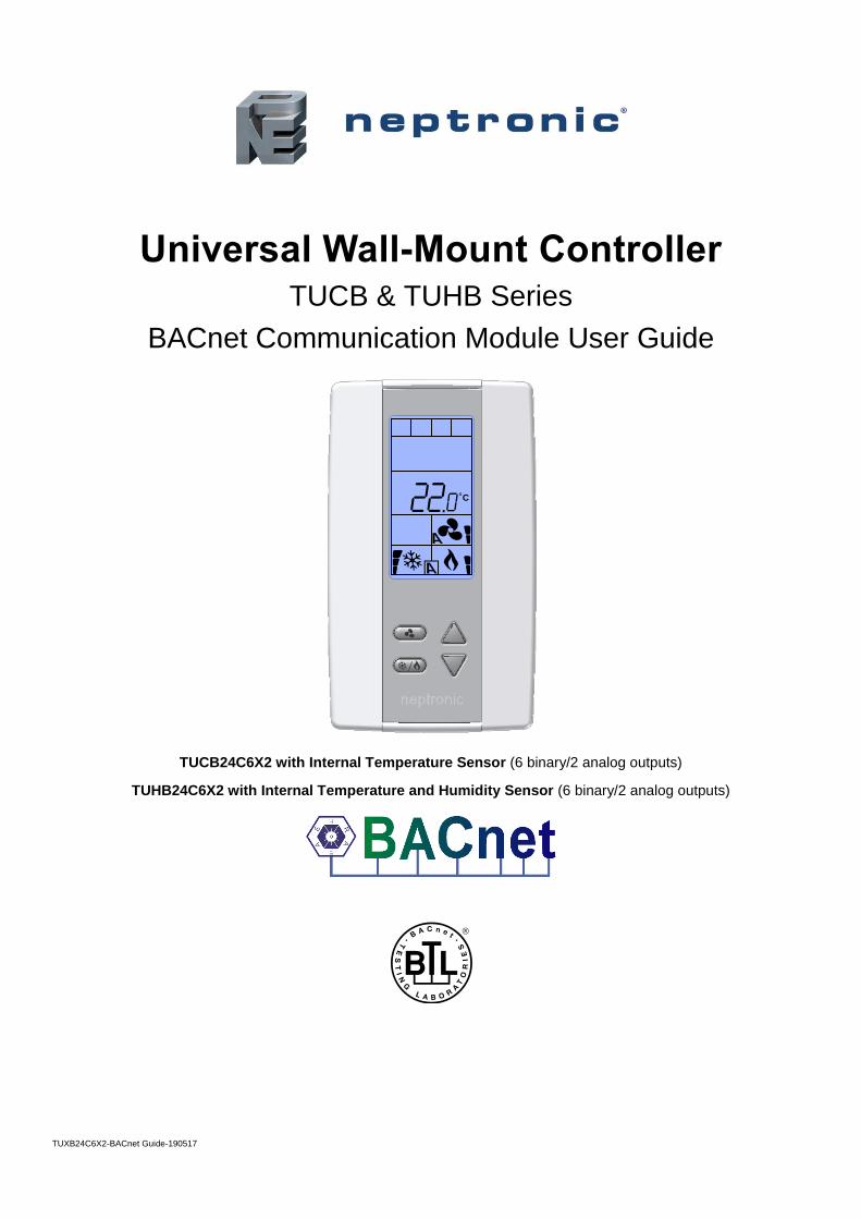
TUXB24C6X2-BACnet Guide-190517 Universal Wall-Mount Controller TUCB & TUHB Series BACnet Communication Module User Guide TUCB24C6X2 with Internal Temperature Sensor (6 binary/2 analog outputs) TUHB24C6X2 with Internal Temperature and Humidity Sensor (6 binary/2 analog outputs) C
Transcript of Universal Wall-Mount Controller - Neptronic · 2020-02-25 · Universal Wall-Mount Controller...
TUXB24C6X2-BACnet Guide-190517
Universal Wall-Mount Controller TUCB & TUHB Series
BACnet Communication Module User Guide
TUCB24C6X2 with Internal Temperature Sensor (6 binary/2 analog outputs)
TUHB24C6X2 with Internal Temperature and Humidity Sensor (6 binary/2 analog outputs)
C
Universal Wall-Mount Controller BACnet Communication Module User Guide
www.neptronic.com Page | i
Contents Introduction ...................................................................................................................................................................... 1
Pre-requisites ................................................................................................................................................................ 1 Advantages of BACnet .................................................................................................................................................. 1 BACnet Properties Configuration .................................................................................................................................. 2
Configuration Options ....................................................................................................................................................... 3 Quick Setup ................................................................................................................................................................... 3 Manual Setup ................................................................................................................................................................ 3
MAC Address and Max_Master ................................................................................................................................ 3
Copy Config ................................................................................................................................................................... 4 Network Reset............................................................................................................................................................... 4
Device Object Properties .................................................................................................................................................. 5 Object Types Supported ................................................................................................................................................ 6 Out of Service Property ................................................................................................................................................. 7
Object Table Information .................................................................................................................................................. 8 Analog Input (AI) ........................................................................................................................................................... 8 Analog Output (AO)....................................................................................................................................................... 8 Analog Value (AV) ......................................................................................................................................................... 9 Binary Input (BI) .......................................................................................................................................................... 14 Binary Output (BO) ...................................................................................................................................................... 14 Binary Value (BV) ........................................................................................................................................................ 15 Multi State Value (MSV) .............................................................................................................................................. 18 Other ........................................................................................................................................................................... 23
Notes ............................................................................................................................................................................... 24

Universal Wall-Mount Controller BACnet Communication Module User Guide
www.neptronic.com Page | 1
Introduction The TUCB & TUHB Series Controller BACnet® Communication Module User Guide provides information about using the controller with BACnet communications feature. The BACnet communication protocol for building automation and control networks enables communication between client devices within a network. The controller provides a BACnet network interface between BACnet client devices and Neptronic Controller series devices. It uses the BACnet Master Slave/Token Passing (MS/TP) protocol at the BACnet MAC layer.
Pre-requisites
The BACnet communication user guide assumes that you are familiar with the concepts of BACnet and its terminology.
Advantages of BACnet
BACnet enabled controllers have the following advantages:
• Quick Message Transmission. The controller uses a synchronous implementation for BACnet messages making it quick and efficient. Each BACnet confirmed service request is answered as quickly as possible without using the Reply Postponed frame. The MS/TP implementation is performed within Tusage_delay of 15 minutes to ensure a Tusage_timeout value within 20 minutes.
• MS/TP Support. The controller supports a Full Master Node state machine for MS/TP. The Max_Master and the instances are configured to the device object through BACnet WriteProperty service or via the device's Programming Mode. The MAC address and the MS/TP baud rate setting of 9600, 19200, 38400, or 76800 are also set through the BACnet Write Property service or via the device's Programming Mode. In Programming mode, the device is configured through the device’s keypad. For more information about the WriteProperty, refer to Table 3 - Object Types Supported.
• BIBB Support. The controller functions the same way as the B-ASC type profile server and supports the specific BIBB as per their relevant definitions.
o DS-RP-B
o DS-RPM-B
o DS-WP-B
o DS-WPM-B
o DM-DCC-B
o DM-DDB-B
o DM-DOB-B
o DM-RD-B
o DM-TS-B
o DM-UTC-B
o DS-COV-B
o DS-COVP-B
o SCHED-WS-I-B
• Object Support. The controller supports a fixed list of BACnet visible values, which appear as Present_Values of various BACnet standard object types in addition to a device object. For more information, refer to Table 3 - Object Types Supported.
• Alarms. The controller supports indication of various alarm conditions through value changes in properties of several objects. However, it does not generate BACnet event notifications.
Universal Wall-Mount Controller BACnet Communication Module User Guide
www.neptronic.com Page | 2
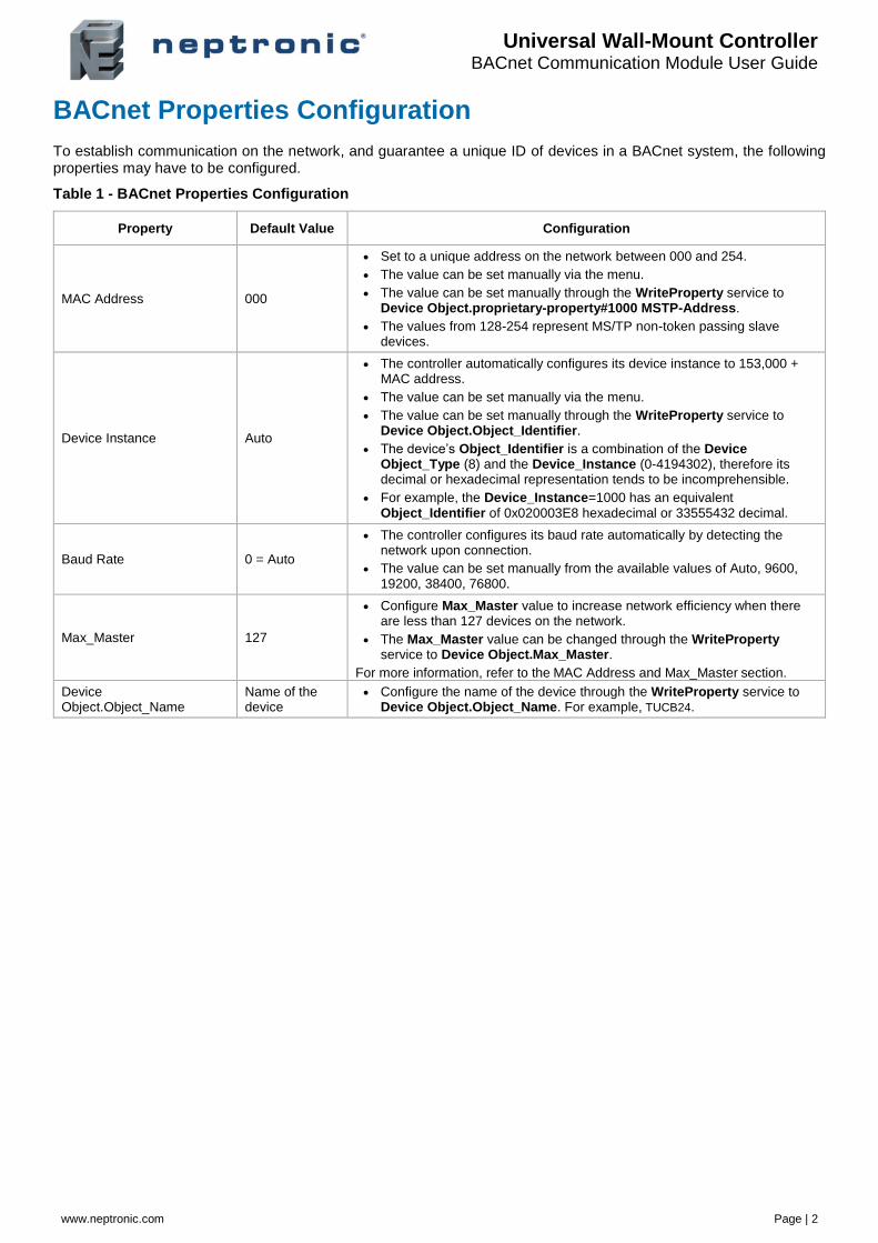
BACnet Properties Configuration
To establish communication on the network, and guarantee a unique ID of devices in a BACnet system, the following properties may have to be configured.
Table 1 - BACnet Properties Configuration
Property Default Value Configuration
MAC Address 000
• Set to a unique address on the network between 000 and 254.
• The value can be set manually via the menu.
• The value can be set manually through the WriteProperty service to Device Object.proprietary-property#1000 MSTP-Address.
• The values from 128-254 represent MS/TP non-token passing slave devices.
Device Instance Auto
• The controller automatically configures its device instance to 153,000 + MAC address.
• The value can be set manually via the menu.
• The value can be set manually through the WriteProperty service to Device Object.Object_Identifier.
• The device’s Object_Identifier is a combination of the Device Object_Type (8) and the Device_Instance (0-4194302), therefore its decimal or hexadecimal representation tends to be incomprehensible.
• For example, the Device_Instance=1000 has an equivalent Object_Identifier of 0x020003E8 hexadecimal or 33555432 decimal.
Baud Rate 0 = Auto
• The controller configures its baud rate automatically by detecting the network upon connection.
• The value can be set manually from the available values of Auto, 9600, 19200, 38400, 76800.
Max_Master 127
• Configure Max_Master value to increase network efficiency when there are less than 127 devices on the network.
• The Max_Master value can be changed through the WriteProperty service to Device Object.Max_Master.
For more information, refer to the MAC Address and Max_Master section.
Device Object.Object_Name
Name of the device
• Configure the name of the device through the WriteProperty service to Device Object.Object_Name. For example, TUCB24.
Universal Wall-Mount Controller BACnet Communication Module User Guide
www.neptronic.com Page | 3
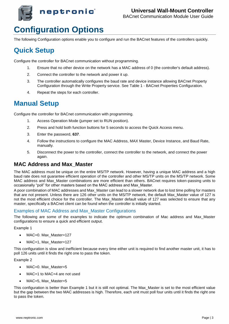
Configuration Options The following Configuration options enable you to configure and run the BACnet features of the controllers quickly.
Quick Setup
Configure the controller for BACnet communication without programming.
1. Ensure that no other device on the network has a MAC address of 0 (the controller's default address).
2. Connect the controller to the network and power it up.
3. The controller automatically configures the baud rate and device instance allowing BACnet Property Configuration through the Write Property service. See Table 1 - BACnet Properties Configuration.
4. Repeat the steps for each controller.
Manual Setup
Configure the controller for BACnet communication with programming.
1. Access Operation Mode (jumper set to RUN position).
2. Press and hold both function buttons for 5 seconds to access the Quick Access menu.
3. Enter the password, 637.
4. Follow the instructions to configure the MAC Address, MAX Master, Device Instance, and Baud Rate, manually.
5. Disconnect the power to the controller, connect the controller to the network, and connect the power again.
MAC Address and Max_Master
The MAC address must be unique on the entire MS/TP network. However, having a unique MAC address and a high baud rate does not guarantee efficient operation of the controller and other MS/TP units on the MS/TP network. Some MAC address and Max_Master combinations are more efficient than others. BACnet requires token-passing units to occasionally “poll” for other masters based on the MAC address and Max_Master.
A poor combination of MAC addresses and Max_Master can lead to a slower network due to lost time polling for masters that are not present. Unless there are 126 other units on the MS/TP network, the default Max_Master value of 127 is not the most efficient choice for the controller. The Max_Master default value of 127 was selected to ensure that any master, specifically a BACnet client can be found when the controller is initially started.
Examples of MAC Address and Max_Master Configurations
The following are some of the examples to indicate the optimum combination of Mac address and Max_Master configurations to ensure a quick and efficient output.
Example 1
• MAC=0. Max_Master=127
• MAC=1, Max_Master=127
This configuration is slow and inefficient because every time either unit is required to find another master unit, it has to poll 126 units until it finds the right one to pass the token.
Example 2
• MAC=0. Max_Master=5
• MAC=1 to MAC=4 are not used
• MAC=5, Max_Master=5
This configuration is better than Example 1 but it is still not optimal. The Max_Master is set to the most efficient value but the gap between the two MAC addresses is high. Therefore, each unit must poll four units until it finds the right one to pass the token.
Universal Wall-Mount Controller BACnet Communication Module User Guide
www.neptronic.com Page | 4
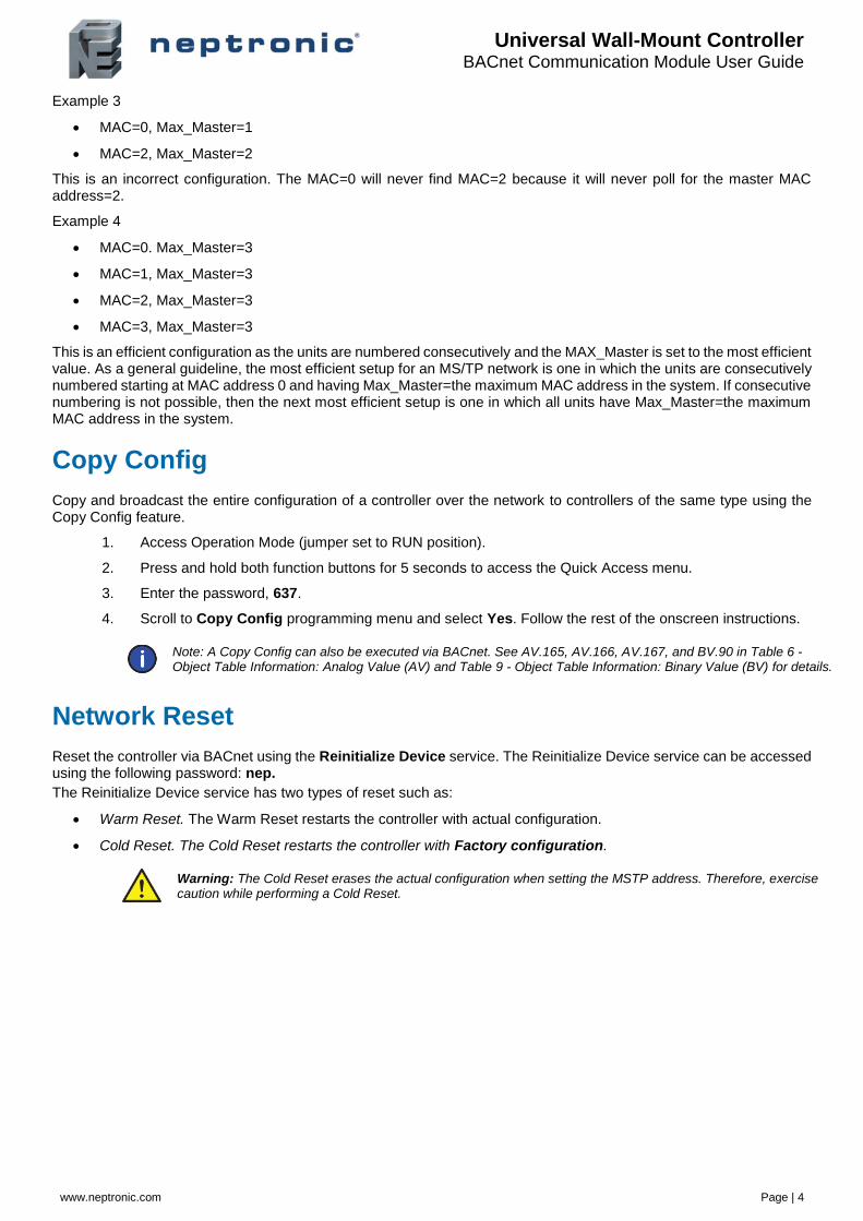
Example 3
• MAC=0, Max_Master=1
• MAC=2, Max_Master=2
This is an incorrect configuration. The MAC=0 will never find MAC=2 because it will never poll for the master MAC address=2.
Example 4
• MAC=0. Max_Master=3
• MAC=1, Max_Master=3
• MAC=2, Max_Master=3
• MAC=3, Max_Master=3
This is an efficient configuration as the units are numbered consecutively and the MAX_Master is set to the most efficient value. As a general guideline, the most efficient setup for an MS/TP network is one in which the units are consecutively numbered starting at MAC address 0 and having Max_Master=the maximum MAC address in the system. If consecutive numbering is not possible, then the next most efficient setup is one in which all units have Max_Master=the maximum MAC address in the system.
Copy Config
Copy and broadcast the entire configuration of a controller over the network to controllers of the same type using the Copy Config feature.
1. Access Operation Mode (jumper set to RUN position).
2. Press and hold both function buttons for 5 seconds to access the Quick Access menu.
3. Enter the password, 637.
4. Scroll to Copy Config programming menu and select Yes. Follow the rest of the onscreen instructions.
Note: A Copy Config can also be executed via BACnet. See AV.165, AV.166, AV.167, and BV.90 in Table 6 - Object Table Information: Analog Value (AV) and Table 9 - Object Table Information: Binary Value (BV) for details.
Network Reset
Reset the controller via BACnet using the Reinitialize Device service. The Reinitialize Device service can be accessed using the following password: nep.
The Reinitialize Device service has two types of reset such as:
• Warm Reset. The Warm Reset restarts the controller with actual configuration.
• Cold Reset. The Cold Reset restarts the controller with Factory configuration.
Warning: The Cold Reset erases the actual configuration when setting the MSTP address. Therefore, exercise caution while performing a Cold Reset.
Universal Wall-Mount Controller BACnet Communication Module User Guide
www.neptronic.com Page | 5
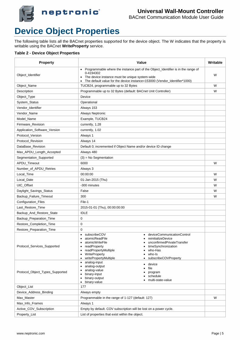
Device Object Properties The following table lists all the BACnet properties supported for the device object. The W indicates that the property is writable using the BACnet WriteProperty service.
Table 2 - Device Object Properties
Property Value Writable
Object_Identifier
• Programmable where the instance part of the Object_Identifier is in the range of 0-4194302
• The device instance must be unique system-wide
• The default value for the device instance=153000 (Vendor_Identifier*1000)
W
Object_Name TUCB24, programmable up to 32 Bytes W
Description Programmable up to 32 Bytes (default: BACnet Unit Controller) W
Object_Type Device
System_Status Operational
Vendor_Identifier Always 153
Vendor_Name Always Neptronic
Model_Name Example, TUCB24
Firmware_Revision currently, 1.28
Application_Software_Version currently, 1.02
Protocol_Version Always 1
Protocol_Revision Always 14
DataBase_Revision Default 0; incremented if Object Name and/or device ID change
Max_APDU_Length_Accepted Always 480
Segmentation_Supported (3) = No Segmentation
APDU_Timeout 6000 W
Number_of_APDU_Retries Always 3
Local_Time 00:00:00 W
Local_Date 01-Jan-2015 (Thu) W
UtC_Offset -300 minutes W
Daylight_Savings_Status False W
Backup_Failure_Timeout 300 W
Configuration_Files File-1
Last_Restore_Time 2015-01-01 (Thu), 00:00:00:00
Backup_And_Restore_State IDLE
Backup_Preparation_Time 0
Restore_Completion_Time 0
Restore_Preparation_Time 0
Protocol_Services_Supported
• subscribeCOV
• atomicReadFile
• atomicWriteFile
• readProperty
• readPropertyMultiple
• WriteProperty
• writePropertyMultiple
• deviceCommunicationControl
• reinitializeDevice
• unconfirmedPrivateTransfer
• timeSynchronization
• who-Has
• who-Is
• subscribeCOVProperty
Protocol_Object_Types_Supported
• analog-input
• analog-output
• analog-value
• binary-input
• binary-output
• binary-value
• device
• file
• program
• schedule
• multi-state-value
Object_List 177
Device_Address_Binding Always empty
Max_Master Programmable in the range of 1-127 (default: 127) W
Max_Info_Frames Always 1
Active_COV_Subscription Empty by default. COV subscription will be lost on a power cycle.
Property_List List of properties that exist within the object.

Universal Wall-Mount Controller BACnet Communication Module User Guide
www.neptronic.com Page | 6
Property Value Writable
Proprietary property #1000
• Programmable (default:0)
• Represents the MS/TP MAC address in the range of 0 to 254
• Values 128 to 254 represent MS/TP non-token passing slave devices
W
Proprietary property #1001
• Programmable (default: Auto)
• Represents the MS/TP Baud rate (unsigned type)
• Values are 0 (Auto), 9600, 19200, 38400, 76800
• Reading this property always returns the actual Baud rate
W
Proprietary property #1002
• Programmable (default: 15 minutes)
• Represents the period of time that an object in/out of service will automatically return to normal. Range = 0-120 minutes (unsigned type)
• Writing 0 means no automatic return to normal
W
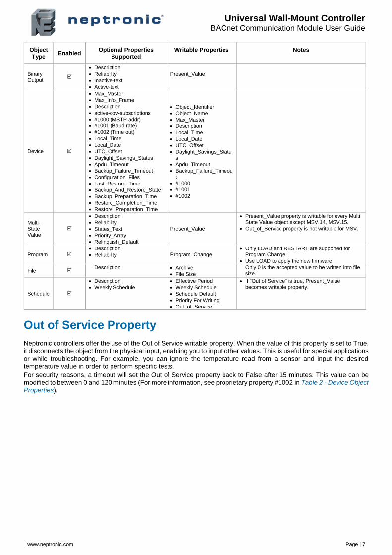
Object Types Supported
The following table lists all the BACnet properties supported for each object type. Most of the properties are locked. The exception is Present_Value, which represents the dynamic operating values of the device, and the Status_Flag, Event_State, and Reliability properties, which reflect the availability of the Present_Value. Unless otherwise specified, properties are not changeable.
Table 3 - Object Types Supported
Object Type
Enabled Optional Properties
Supported Writable Properties Notes
Note: Writable properties are different for some objects. Refer to the respective Object Table information to know the writable property for objects.
Analog Input
• Reliability
• Description
• Min_Present_Value
• Max_Present_Value
• Resolution
• Cov-increment
• Out_of_Service
• Cov-Increment
• If "Out of Service" is true, Present_Value and Status_Flag become writable properties. Refer to Out of Service Property section on page 7 for more information.
• Object will automatically return to Normal after a programmable period of time. Refer to Proprietary property #1002 of Device Object in Table 2 - Device Object Properties.
Analog Value
• Reliability
• Description
• Cov-Increment
• Priority_Array
• Relinquish_Default
• Present_Value
• Out_of_Service
• Cov-Increment
• Present_Value property is writable for every AV object except AV.20, AV.24, AV.35, AV.38, AV.50, AV.60, AV.78, AV.79, AV.87.
• Out_of_Service property is writable for AV.1, AV.3, AV.4, AV.70, AV.95.
• Refer to Out of Service Property section on page 7 for more information.
• Object will automatically return to Normal after a programmable period of time. Refer to Proprietary property #1002 of Device Object in Table 2 - Device Object Properties.
Analog Output
• Description
• Reliability
• Min-Pres-Value
• Max-Pres-Value
• Resolution
• Cov-Increment
• Present_Value
• Cov-Increment
Binary Input
• Reliability
• Active_Text
• Inactive_Text
• Description
Out_of_Service
• If "Out of Service" is true, Present_Value and Status_Flag become writable properties. Refer to Out of Service Property section on page 7 for more information.
• Object will automatically return to Normal after a programmable period of time. Refer to Proprietary property #1002 of Device Object in Table 2 - Device Object Properties.
Binary Value
• Reliability
• Active_Text
• Inactive_Text
• Description
• Priority_Array
• Relinquish_Default
Present_Value Out_of_Service
• Present_Value property is writable for every Binary Value object except BV.36 and BV.42.
• Out_of_Service property is writable for BV.30.
• Some objects are commandable. In such case, the priority-array and relinquish-default properties are available for BV.30.
• Object automatically returns to Normal after a programmable time. Refer to Proprietary property #1002 of Device Object in Table 2 - Device Object Properties.
Universal Wall-Mount Controller BACnet Communication Module User Guide
www.neptronic.com Page | 7
Object Type
Enabled Optional Properties
Supported Writable Properties Notes
Binary Output
• Description
• Reliability
• Inactive-text
• Active-text
Present_Value
Device
• Max_Master
• Max_Info_Frame
• Description
• active-cov-subscriptions
• #1000 (MSTP addr) • #1001 (Baud rate)
• #1002 (Time out)
• Local_Time
• Local_Date
• UTC_Offset
• Daylight_Savings_Status
• Apdu_Timeout
• Backup_Failure_Timeout
• Configuration_Files
• Last_Restore_Time
• Backup_And_Restore_State
• Backup_Preparation_Time
• Restore_Completion_Time
• Restore_Preparation_Time
• Object_Identifier
• Object_Name
• Max_Master
• Description
• Local_Time
• Local_Date
• UTC_Offset
• Daylight_Savings_Status
• Apdu_Timeout
• Backup_Failure_Timeout
• #1000
• #1001
• #1002
Multi-State Value
• Description
• Reliability
• States_Text
• Priority_Array
• Relinquish_Default
Present_Value
• Present_Value property is writable for every Multi State Value object except MSV.14, MSV.15.
• Out_of_Service property is not writable for MSV.
Program • Description
• Reliability Program_Change • Only LOAD and RESTART are supported for
Program Change.
• Use LOAD to apply the new firmware.
File Description • Archive
• File Size Only 0 is the accepted value to be written into file size.
Schedule
• Description
• Weekly Schedule • Effective Period
• Weekly Schedule
• Schedule Default
• Priority For Writing
• Out_of_Service
• If "Out of Service" is true, Present_Value becomes writable property.
Out of Service Property
Neptronic controllers offer the use of the Out of Service writable property. When the value of this property is set to True, it disconnects the object from the physical input, enabling you to input other values. This is useful for special applications or while troubleshooting. For example, you can ignore the temperature read from a sensor and input the desired temperature value in order to perform specific tests.
For security reasons, a timeout will set the Out of Service property back to False after 15 minutes. This value can be modified to between 0 and 120 minutes (For more information, see proprietary property #1002 in Table 2 - Device Object Properties).
Universal Wall-Mount Controller BACnet Communication Module User Guide
www.neptronic.com Page | 8
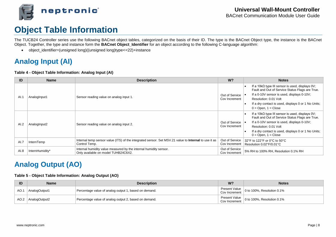
Object Table Information The TUCB24 Controller series use the following BACnet object tables, categorized on the basis of their ID. The type is the BACnet Object type, the instance is the BACnet Object. Together, the type and instance form the BACnet Object_Identifier for an object according to the following C-language algorithm:
• object_identifier=(unsigned long)((unsigned long)type<<22)+instance
Analog Input (AI)
Table 4 - Object Table Information: Analog Input (AI)
ID Name Description W? Notes
AI.1 AnalogInput1 Sensor reading value on analog input 1. Out of Service Cov Increment
• If a 10kΩ type III sensor is used, displays 0V; Fault and Out of Service Status Flags are True.
• If a 0-10V sensor is used, displays 0-10V;
Resolution: 0.01 Volt
• If a dry contact is used, displays 0 or 1 No Units;
0 = Open, 1 = Close
AI.2 AnalogInput2 Sensor reading value on analog input 2. Out of Service Cov Increment
• If a 10kΩ type III sensor is used, displays 0V; Fault and Out of Service Status Flags are True.
• If a 0-10V sensor is used, displays 0-10V;
Resolution: 0.01 Volt
• If a dry contact is used, displays 0 or 1 No Units; 0 = Open, 1 = Close
AI.7 InternTemp Internal temp sensor value (ITS) of the integrated sensor. Set MSV.21 value to Internal to use it as Control Temp.
Out of Service Cov Increment
32°F to 122°F or 0°C to 50°C Resolution 0.02°F/0.01°C
AI.8 InternHumidity* Internal humidity value measured by the internal humidity sensor. Only available on model TUHB24C6X2.
Out of Service Cov Increment 5% RH to 100% RH, Resolution 0.1% RH
Analog Output (AO)
Table 5 - Object Table Information: Analog Output (AO)
ID Name Description W? Notes
AO.1 AnalogOutput1 Percentage value of analog output 1, based on demand. Present Value Cov Increment
0 to 100%, Resolution 0.1%
AO.2 AnalogOutput2 Percentage value of analog output 2, based on demand. Present Value Cov Increment
0 to 100%, Resolution 0.1%
Universal Wall-Mount Controller BACnet Communication Module User Guide
www.neptronic.com Page | 9
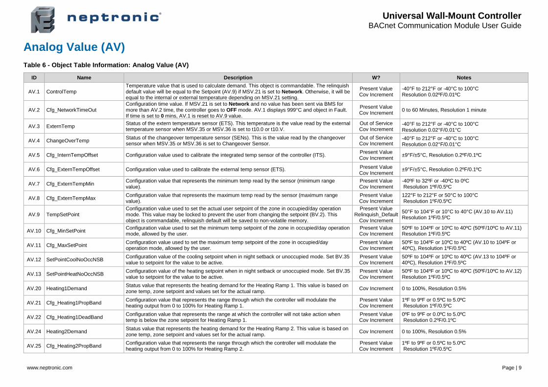
Analog Value (AV)
Table 6 - Object Table Information: Analog Value (AV)
ID Name Description W? Notes
AV.1 ControlTemp Temperature value that is used to calculate demand. This object is commandable. The relinquish default value will be equal to the Setpoint (AV.9) if MSV.21 is set to Network. Otherwise, it will be equal to the internal or external temperature depending on MSV.21 setting.
Present Value Cov Increment
-40°F to 212°F or -40°C to 100°C Resolution 0.02ºF/0.01ºC
AV.2 Cfg_NetworkTimeOut Configuration time value. If MSV.21 is set to Network and no value has been sent via BMS for more than AV.2 time, the controller goes to OFF mode. AV.1 displays 999°C and object in Fault. If time is set to 0 mins, AV.1 is reset to AV.9 value.
Present Value Cov Increment
0 to 60 Minutes, Resolution 1 minute
AV.3 ExternTemp Status of the extern temperature sensor (ETS). This temperature is the value read by the external temperature sensor when MSV.35 or MSV.36 is set to t10.0 or t10.V.
Out of Service Cov Increment
-40°F to 212°F or -40°C to 100°C Resolution 0.02°F/0.01°C
AV.4 ChangeOverTemp Status of the changeover temperature sensor (SENs). This is the value read by the changeover sensor when MSV.35 or MSV.36 is set to Changeover Sensor.
Out of Service Cov Increment
-40°F to 212°F or -40°C to 100°C Resolution 0.02°F/0.01°C
AV.5 Cfg_InternTempOffset Configuration value used to calibrate the integrated temp sensor of the controller (ITS). Present Value Cov Increment
±9°F/±5°C, Resolution 0.2ºF/0.1ºC
AV.6 Cfg_ExternTempOffset Configuration value used to calibrate the external temp sensor (ETS). Present Value Cov Increment
±9°F/±5°C, Resolution 0.2ºF/0.1ºC
AV.7 Cfg_ExternTempMin Configuration value that represents the minimum temp read by the sensor (minimum range value).
Present Value Cov Increment
-40ºF to 32ºF or -40ºC to 0ºC Resolution 1ºF/0.5ºC
AV.8 Cfg_ExternTempMax Configuration value that represents the maximum temp read by the sensor (maximum range value).
Present Value Cov Increment
122°F to 212°F or 50°C to 100°C Resolution 1ºF/0.5ºC
AV.9 TempSetPoint Configuration value used to set the actual user setpoint of the zone in occupied/day operation mode. This value may be locked to prevent the user from changing the setpoint (BV.2). This object is commandable, relinquish default will be saved to non-volatile memory.
Present Value Relinquish_Default
Cov Increment
50°F to 104°F or 10°C to 40°C (AV.10 to AV.11) Resolution 1ºF/0.5ºC
AV.10 Cfg_MinSetPoint Configuration value used to set the minimum temp setpoint of the zone in occupied/day operation mode, allowed by the user.
Present Value Cov Increment
50ºF to 104ºF or 10ºC to 40ºC (50ºF/10ºC to AV.11) Resolution 1ºF/0.5ºC
AV.11 Cfg_MaxSetPoint Configuration value used to set the maximum temp setpoint of the zone in occupied/day operation mode, allowed by the user.
Present Value Cov Increment
50ºF to 104ºF or 10ºC to 40ºC (AV.10 to 104ºF or 40ºC), Resolution 1ºF/0.5ºC
AV.12 SetPointCoolNoOccNSB Configuration value of the cooling setpoint when in night setback or unoccupied mode. Set BV.35 value to setpoint for the value to be active.
Present Value Cov Increment
50ºF to 104ºF or 10ºC to 40ºC (AV.13 to 104ºF or 40ºC), Resolution 1ºF/0.5ºC
AV.13 SetPointHeatNoOccNSB Configuration value of the heating setpoint when in night setback or unoccupied mode. Set BV.35 value to setpoint for the value to be active.
Present Value Cov Increment
50ºF to 104ºF or 10ºC to 40ºC (50ºF/10ºC to AV.12) Resolution 1ºF/0.5ºC
AV.20 Heating1Demand Status value that represents the heating demand for the Heating Ramp 1. This value is based on zone temp, zone setpoint and values set for the actual ramp.
Cov Increment 0 to 100%, Resolution 0.5%
AV.21 Cfg_Heating1PropBand Configuration value that represents the range through which the controller will modulate the heating output from 0 to 100% for Heating Ramp 1.
Present Value Cov Increment
1ºF to 9ºF or 0.5ºC to 5.0ºC Resolution 1ºF/0.5ºC
AV.22 Cfg_Heating1DeadBand Configuration value that represents the range at which the controller will not take action when temp is below the zone setpoint for Heating Ramp 1.
Present Value Cov Increment
0ºF to 9ºF or 0.0ºC to 5.0ºC Resolution 0.2ºF/0.1ºC
AV.24 Heating2Demand Status value that represents the heating demand for the Heating Ramp 2. This value is based on zone temp, zone setpoint and values set for the actual ramp.
Cov Increment 0 to 100%, Resolution 0.5%
AV.25 Cfg_Heating2PropBand Configuration value that represents the range through which the controller will modulate the heating output from 0 to 100% for Heating Ramp 2.
Present Value Cov Increment
1ºF to 9ºF or 0.5ºC to 5.0ºC Resolution 1ºF/0.5ºC

Universal Wall-Mount Controller BACnet Communication Module User Guide
www.neptronic.com Page | 10
ID Name Description W? Notes
AV.26 Cfg_Heating2DeadBand Configuration value that represents the range at which the controller will not take action when temp is below the zone setpoint for Heating Ramp 2.
Present Value Cov Increment
0ºF to 9ºF or 0.0ºC to 5.0ºC Resolution 0.2ºF/0.1ºC
AV.32 Cfg_IntegralTimeHeating Configuration value that represents the reciprocal of the integral time in secs (1/I or repeats per second). To obtain a slower reaction time, the value of the integral must be small. To obtain a quicker reaction time, the integral value must be bigger.
Present Value Cov Increment
0 to 250 seconds, Resolution 5 seconds
AV.35 Cooling1Demand Status value that represents the cooling demand for the Cooling Ramp 1. This value is based on zone temp, zone setpoint and values set for the actual ramp.
Cov Increment 0 to 100%, Resolution 0.5%
AV.36 Cfg_Cooling1PropBand Configuration value that represents the range through which the controller will modulate the cooling output from 0 to 100% for Cooling Ramp 1.
Present Value Cov Increment
1ºF to 9ºF or 0.5ºC to 5.0ºC Resolution 1ºF/0.5ºC
AV.37 Cfg_Cooling1DeadBand Configuration value that represents the range at which the controller will not take action when temp is above the zone setpoint for Cooling Ramp 1.
Present Value Cov Increment
0ºF to 9ºF or 0.0ºC to 5.0ºC Resolution 0.2ºF/0.1ºC
AV.38 Cooling2Demand Status value that represents the cooling demand for the Cooling Ramp 2. This value is based on zone temp, zone setpoint and values set for the actual ramp.
Cov Increment 0 to 100%, Resolution 0.5%
AV.39 Cfg_Cooling2PropBand Configuration value that represents the range through which the controller will modulate the cooling output from 0 to 100% for Cooling Ramp 2.
Present Value Cov Increment
1ºF to 9ºF or 0.5ºC to 5.0ºC Resolution 1ºF/0.5ºC
AV.40 Cfg_Cooling2DeadBand Configuration value that represents the range at which the controller will not take action when temp is above the zone setpoint for Cooling Ramp 2.
Present Value Cov Increment
0ºF to 9ºF or 0.0ºC to 5.0ºC Resolution 0.2ºF/0.1ºC
AV.45 Cfg_IntegralTimeCooling Configuration value that represents the reciprocal of the integral time in secs (1/I or repeats per second). To obtain a slower reaction time, the value of the integral must be small. To obtain a quicker reaction time, the integral value must be bigger.
Present Value Cov Increment
0 to 250 seconds, Resolution 5 seconds
AV.46 Cfg_CoolingAntiCycleDelay Configuration value in mins to prevent the cooling outputs to cycle on and off. This is a protection feature used when cooling is done through compressors.
Present Value Cov Increment
0 to15 minutes, Resolution 1 minute
AV.50 ChangeOverDemand Status value that represents the changeover demand. This value is based on changeover temp, setpoint, and values set for the actual ramp.
Cov Increment 0 to 100%, Resolution 0.5%
AV.51 Cfg_ChangeOverPropBand Configuration value that represents the range through which the controller modulates the changeover output from 0 to 100%.
Present Value Cov Increment
1ºF to 9ºF or 0.5ºC to 5.0ºC Resolution 1ºF/0.5ºC
AV.52 Cfg_ChangeOverDeadBand Configuration value that represents the range at which the controller will not take action on the changeover output when above or below the changeover setpoint.
Present Value Cov Increment
0ºF to 9ºF or 0.0ºC to 5.0ºC Resolution 1ºF/0.5ºC
AV.53 ChangeOverSetPoint Configuration value of the temp at which the water that enters is considered to be in cooling or heating state.
Present Value Cov Increment
50ºF to 104ºF or 10ºC to 40ºC Resolution 1ºF/0.5ºC
AV.56 Cfg_CL_HT_SwitchTimer Configuration value of the time required before the changeover is permitted to take place (time in mins).
Present Value Cov Increment
0 to 120 minutes, Resolution 1 minute
AV.58 CL_HT_SwitchTimerCount Status value of the remaining time before the changeover is authorised. This value counts down from the time set in AV.56.
Cov Increment 0 to 7,200 seconds, Resolution 1 second
AV.60 FanDemand Status value that represents the fan demand. This value is based on the status value of other demands. Demand is also affected by the number of fan speed configured in MSV.25.
Cov Increment 0 to 100%, Resolution 0.5%
AV.61 Cfg_FanAutoTimeOutDelay Configuration value to prevent the cycling of the fan. If the fan was in operation, the controller will countdown from this value before stopping the fan.
Present Value Cov Increment
0 to 255 seconds, Resolution 1 second
AV.62 Cfg_FanDampingFactor Configuration value in secs that represents the damping factor for changing fan speed. Present Value Cov Increment
0 to 255 seconds, Resolution 1 second
AV.70 ExternHumidity External humidity sensor value (Erh). Out of Service Cov Increment
5% RH to 95% RH, Resolution 0.1% RH
AV.71 Cfg_InternHumidityOffset* Configuration value used to calibrate the internal relative humidity sensor (irh). Only available on model TUHB24C6X2.
Present Value Cov Increment
± 5%, Resolution 0.1% RH
Universal Wall-Mount Controller BACnet Communication Module User Guide
www.neptronic.com Page | 11
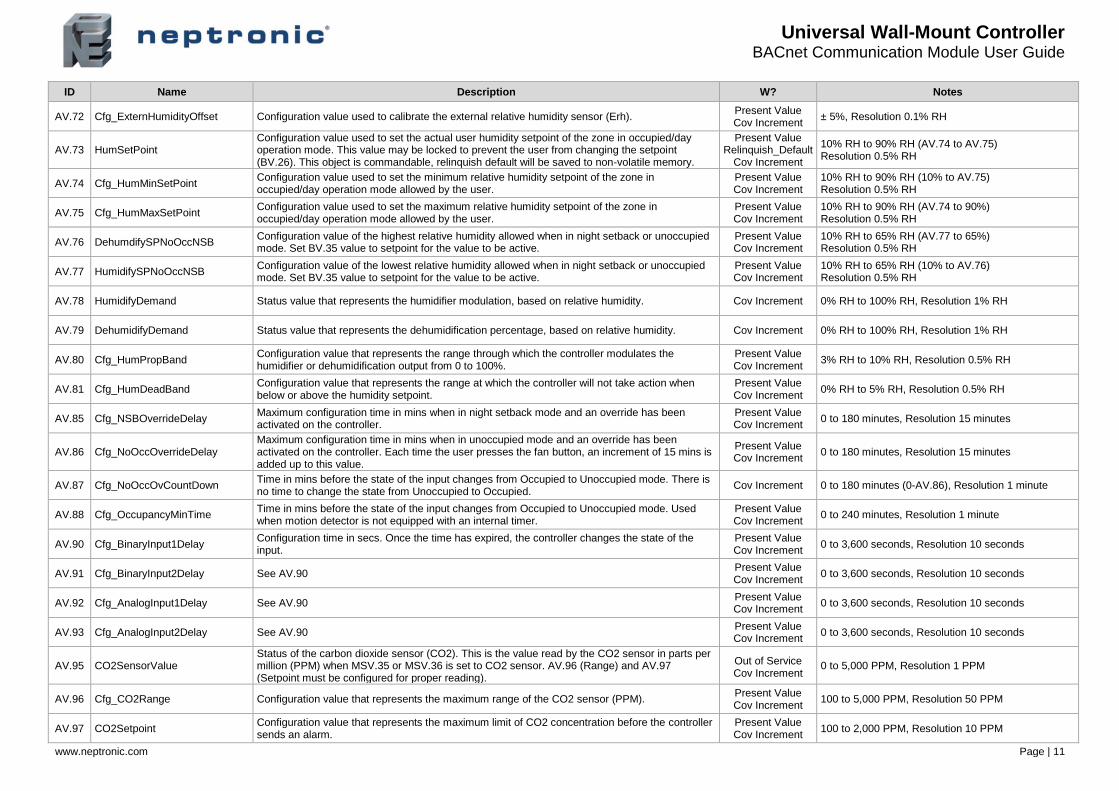
ID Name Description W? Notes
AV.72 Cfg_ExternHumidityOffset Configuration value used to calibrate the external relative humidity sensor (Erh). Present Value Cov Increment
± 5%, Resolution 0.1% RH
AV.73 HumSetPoint Configuration value used to set the actual user humidity setpoint of the zone in occupied/day operation mode. This value may be locked to prevent the user from changing the setpoint (BV.26). This object is commandable, relinquish default will be saved to non-volatile memory.
Present Value Relinquish_Default
Cov Increment
10% RH to 90% RH (AV.74 to AV.75) Resolution 0.5% RH
AV.74 Cfg_HumMinSetPoint Configuration value used to set the minimum relative humidity setpoint of the zone in occupied/day operation mode allowed by the user.
Present Value Cov Increment
10% RH to 90% RH (10% to AV.75) Resolution 0.5% RH
AV.75 Cfg_HumMaxSetPoint Configuration value used to set the maximum relative humidity setpoint of the zone in occupied/day operation mode allowed by the user.
Present Value Cov Increment
10% RH to 90% RH (AV.74 to 90%) Resolution 0.5% RH
AV.76 DehumdifySPNoOccNSB Configuration value of the highest relative humidity allowed when in night setback or unoccupied mode. Set BV.35 value to setpoint for the value to be active.
Present Value Cov Increment
10% RH to 65% RH (AV.77 to 65%) Resolution 0.5% RH
AV.77 HumidifySPNoOccNSB Configuration value of the lowest relative humidity allowed when in night setback or unoccupied mode. Set BV.35 value to setpoint for the value to be active.
Present Value Cov Increment
10% RH to 65% RH (10% to AV.76) Resolution 0.5% RH
AV.78 HumidifyDemand Status value that represents the humidifier modulation, based on relative humidity. Cov Increment 0% RH to 100% RH, Resolution 1% RH
AV.79 DehumidifyDemand Status value that represents the dehumidification percentage, based on relative humidity. Cov Increment 0% RH to 100% RH, Resolution 1% RH
AV.80 Cfg_HumPropBand Configuration value that represents the range through which the controller modulates the humidifier or dehumidification output from 0 to 100%.
Present Value Cov Increment
3% RH to 10% RH, Resolution 0.5% RH
AV.81 Cfg_HumDeadBand Configuration value that represents the range at which the controller will not take action when below or above the humidity setpoint.
Present Value Cov Increment
0% RH to 5% RH, Resolution 0.5% RH
AV.85 Cfg_NSBOverrideDelay Maximum configuration time in mins when in night setback mode and an override has been activated on the controller.
Present Value Cov Increment
0 to 180 minutes, Resolution 15 minutes
AV.86 Cfg_NoOccOverrideDelay Maximum configuration time in mins when in unoccupied mode and an override has been activated on the controller. Each time the user presses the fan button, an increment of 15 mins is added up to this value.
Present Value Cov Increment
0 to 180 minutes, Resolution 15 minutes
AV.87 Cfg_NoOccOvCountDown Time in mins before the state of the input changes from Occupied to Unoccupied mode. There is no time to change the state from Unoccupied to Occupied.
Cov Increment 0 to 180 minutes (0-AV.86), Resolution 1 minute
AV.88 Cfg_OccupancyMinTime Time in mins before the state of the input changes from Occupied to Unoccupied mode. Used when motion detector is not equipped with an internal timer.
Present Value Cov Increment
0 to 240 minutes, Resolution 1 minute
AV.90 Cfg_BinaryInput1Delay Configuration time in secs. Once the time has expired, the controller changes the state of the input.
Present Value Cov Increment
0 to 3,600 seconds, Resolution 10 seconds
AV.91 Cfg_BinaryInput2Delay See AV.90 Present Value Cov Increment
0 to 3,600 seconds, Resolution 10 seconds
AV.92 Cfg_AnalogInput1Delay See AV.90 Present Value Cov Increment
0 to 3,600 seconds, Resolution 10 seconds
AV.93 Cfg_AnalogInput2Delay See AV.90 Present Value Cov Increment
0 to 3,600 seconds, Resolution 10 seconds
AV.95 CO2SensorValue Status of the carbon dioxide sensor (CO2). This is the value read by the CO2 sensor in parts per million (PPM) when MSV.35 or MSV.36 is set to CO2 sensor. AV.96 (Range) and AV.97 (Setpoint must be configured for proper reading).
Out of Service Cov Increment
0 to 5,000 PPM, Resolution 1 PPM
AV.96 Cfg_CO2Range Configuration value that represents the maximum range of the CO2 sensor (PPM). Present Value Cov Increment
100 to 5,000 PPM, Resolution 50 PPM
AV.97 CO2Setpoint Configuration value that represents the maximum limit of CO2 concentration before the controller sends an alarm.
Present Value Cov Increment
100 to 2,000 PPM, Resolution 10 PPM
Universal Wall-Mount Controller BACnet Communication Module User Guide
www.neptronic.com Page | 12
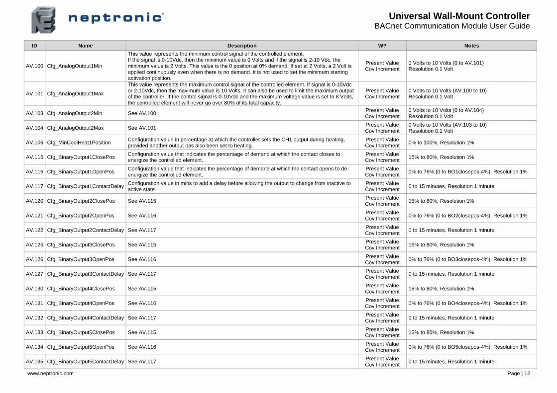
ID Name Description W? Notes
AV.100 Cfg_AnalogOutput1Min
This value represents the minimum control signal of the controlled element. If the signal is 0-10Vdc, then the minimum value is 0 Volts and if the signal is 2-10 Vdc, the minimum value is 2 Volts. This value is the 0 position at 0% demand. If set at 2 Volts, a 2 Volt is applied continuously even when there is no demand. It is not used to set the minimum starting activation position.
Present Value Cov Increment
0 Volts to 10 Volts (0 to AV.101) Resolution 0.1 Volt
AV.101 Cfg_AnalogOutput1Max
This value represents the maximum control signal of the controlled element. If signal is 0-10Vdc or 2-10Vdc, then the maximum value is 10 Volts. It can also be used to limit the maximum output of the controller. If the control signal is 0-10Vdc and the maximum voltage value is set to 8 Volts, the controlled element will never go over 80% of its total capacity.
Present Value Cov Increment
0 Volts to 10 Volts (AV.100 to 10) Resolution 0.1 Volt
AV.103 Cfg_AnalogOutput2Min See AV.100 Present Value Cov Increment
0 Volts to 10 Volts (0 to AV.104) Resolution 0.1 Volt
AV.104 Cfg_AnalogOutput2Max See AV.101 Present Value Cov Increment
0 Volts to 10 Volts (AV.103 to 10) Resolution 0.1 Volt
AV.106 Cfg_MinCoolHeat1Position Configuration value in percentage at which the controller sets the CH1 output during heating, provided another output has also been set to heating.
Present Value Cov Increment
0% to 100%, Resolution 1%
AV.115 Cfg_BinaryOutput1ClosePos Configuration value that indicates the percentage of demand at which the contact closes to energize the controlled element.
Present Value Cov Increment
15% to 80%, Resolution 1%
AV.116 Cfg_BinaryOutput1OpenPos Configuration value that indicates the percentage of demand at which the contact opens to de-energize the controlled element.
Present Value Cov Increment
0% to 76% (0 to BO1closepos-4%), Resolution 1%
AV.117 Cfg_BinaryOutput1ContactDelay Configuration value in mins to add a delay before allowing the output to change from inactive to active state.
Present Value Cov Increment
0 to 15 minutes, Resolution 1 minute
AV.120 Cfg_BinaryOutput2ClosePos See AV.115 Present Value Cov Increment
15% to 80%, Resolution 1%
AV.121 Cfg_BinaryOutput2OpenPos See AV.116 Present Value Cov Increment
0% to 76% (0 to BO2closepos-4%), Resolution 1%
AV.122 Cfg_BinaryOutput2ContactDelay See AV.117 Present Value Cov Increment
0 to 15 minutes, Resolution 1 minute
AV.125 Cfg_BinaryOutput3ClosePos See AV.115 Present Value Cov Increment
15% to 80%, Resolution 1%
AV.126 Cfg_BinaryOutput3OpenPos See AV.116 Present Value Cov Increment
0% to 76% (0 to BO3closepos-4%), Resolution 1%
AV.127 Cfg_BinaryOutput3ContactDelay See AV.117 Present Value Cov Increment
0 to 15 minutes, Resolution 1 minute
AV.130 Cfg_BinaryOutput4ClosePos See AV.115 Present Value Cov Increment
15% to 80%, Resolution 1%
AV.131 Cfg_BinaryOutput4OpenPos See AV.116 Present Value Cov Increment
0% to 76% (0 to BO4closepos-4%), Resolution 1%
AV.132 Cfg_BinaryOutput4ContactDelay See AV.117 Present Value Cov Increment
0 to 15 minutes, Resolution 1 minute
AV.133 Cfg_BinaryOutput5ClosePos See AV.115 Present Value Cov Increment
15% to 80%, Resolution 1%
AV.134 Cfg_BinaryOutput5OpenPos See AV.116 Present Value Cov Increment
0% to 76% (0 to BO5closepos-4%), Resolution 1%
AV.135 Cfg_BinaryOutput5ContactDelay See AV.117 Present Value Cov Increment
0 to 15 minutes, Resolution 1 minute
Universal Wall-Mount Controller BACnet Communication Module User Guide
www.neptronic.com Page | 13
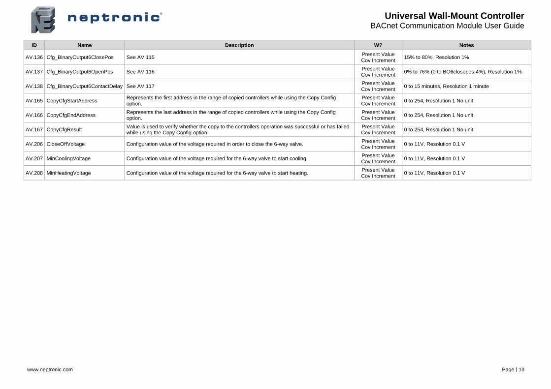
ID Name Description W? Notes
AV.136 Cfg_BinaryOutput6ClosePos See AV.115 Present Value Cov Increment
15% to 80%, Resolution 1%
AV.137 Cfg_BinaryOutput6OpenPos See AV.116 Present Value Cov Increment
0% to 76% (0 to BO6closepos-4%), Resolution 1%
AV.138 Cfg_BinaryOutput6ContactDelay See AV.117 Present Value Cov Increment
0 to 15 minutes, Resolution 1 minute
AV.165 CopyCfgStartAddress Represents the first address in the range of copied controllers while using the Copy Config option.
Present Value Cov Increment
0 to 254, Resolution 1 No unit
AV.166 CopyCfgEndAddress Represents the last address in the range of copied controllers while using the Copy Config option.
Present Value Cov Increment
0 to 254, Resolution 1 No unit
AV.167 CopyCfgResult Value is used to verify whether the copy to the controllers operation was successful or has failed while using the Copy Config option.
Present Value Cov Increment
0 to 254, Resolution 1 No unit
AV.206 CloseOffVoltage Configuration value of the voltage required in order to close the 6-way valve. Present Value Cov Increment
0 to 11V, Resolution 0.1 V
AV.207 MinCoolingVoltage Configuration value of the voltage required for the 6-way valve to start cooling. Present Value Cov Increment
0 to 11V, Resolution 0.1 V
AV.208 MinHeatingVoltage Configuration value of the voltage required for the 6-way valve to start heating. Present Value Cov Increment
0 to 11V, Resolution 0.1 V
Universal Wall-Mount Controller BACnet Communication Module User Guide
www.neptronic.com Page | 14
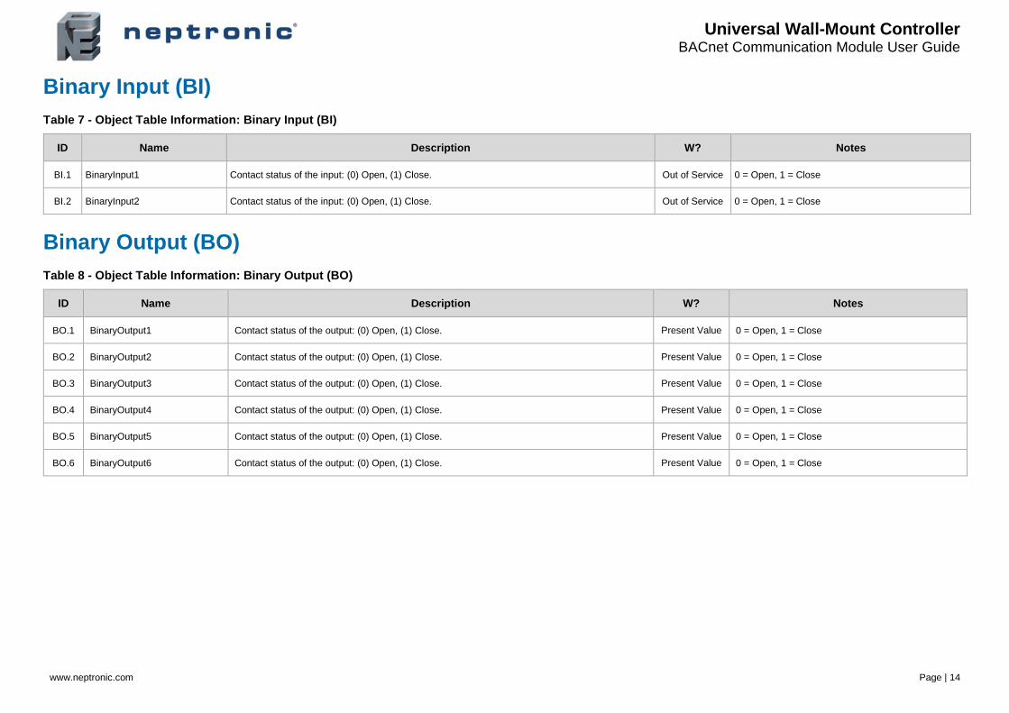
Binary Input (BI)
Table 7 - Object Table Information: Binary Input (BI)
ID Name Description W? Notes
BI.1 BinaryInput1 Contact status of the input: (0) Open, (1) Close. Out of Service 0 = Open, 1 = Close
BI.2 BinaryInput2 Contact status of the input: (0) Open, (1) Close. Out of Service 0 = Open, 1 = Close
Binary Output (BO)
Table 8 - Object Table Information: Binary Output (BO)
ID Name Description W? Notes
BO.1 BinaryOutput1 Contact status of the output: (0) Open, (1) Close. Present Value 0 = Open, 1 = Close
BO.2 BinaryOutput2 Contact status of the output: (0) Open, (1) Close. Present Value 0 = Open, 1 = Close
BO.3 BinaryOutput3 Contact status of the output: (0) Open, (1) Close. Present Value 0 = Open, 1 = Close
BO.4 BinaryOutput4 Contact status of the output: (0) Open, (1) Close. Present Value 0 = Open, 1 = Close
BO.5 BinaryOutput5 Contact status of the output: (0) Open, (1) Close. Present Value 0 = Open, 1 = Close
BO.6 BinaryOutput6 Contact status of the output: (0) Open, (1) Close. Present Value 0 = Open, 1 = Close
Universal Wall-Mount Controller BACnet Communication Module User Guide
www.neptronic.com Page | 15
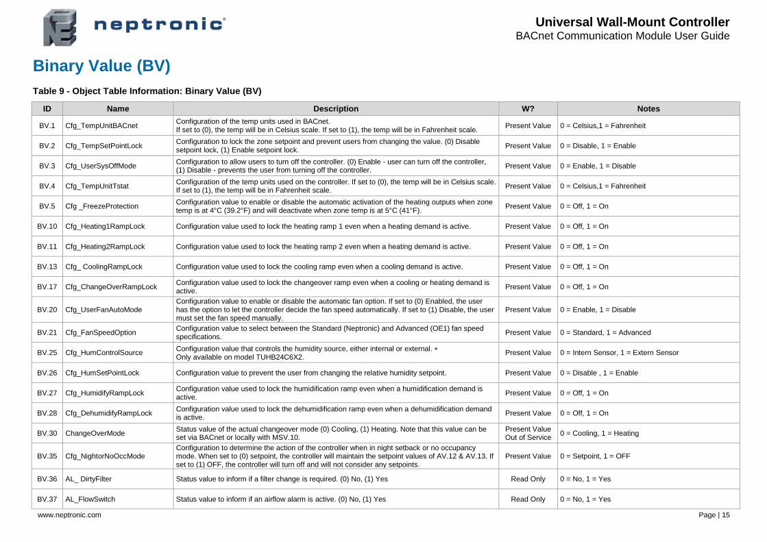
Binary Value (BV)
Table 9 - Object Table Information: Binary Value (BV)
ID Name Description W? Notes
BV.1 Cfg_TempUnitBACnet Configuration of the temp units used in BACnet. If set to (0), the temp will be in Celsius scale. If set to (1), the temp will be in Fahrenheit scale.
Present Value 0 = Celsius,1 = Fahrenheit
BV.2 Cfg_TempSetPointLock Configuration to lock the zone setpoint and prevent users from changing the value. (0) Disable setpoint lock, (1) Enable setpoint lock.
Present Value 0 = Disable, 1 = Enable
BV.3 Cfg_UserSysOffMode Configuration to allow users to turn off the controller. (0) Enable - user can turn off the controller, (1) Disable - prevents the user from turning off the controller.
Present Value 0 = Enable, 1 = Disable
BV.4 Cfg_TempUnitTstat Configuration of the temp units used on the controller. If set to (0), the temp will be in Celsius scale. If set to (1), the temp will be in Fahrenheit scale.
Present Value 0 = Celsius,1 = Fahrenheit
BV.5 Cfg _FreezeProtection Configuration value to enable or disable the automatic activation of the heating outputs when zone temp is at 4°C (39.2°F) and will deactivate when zone temp is at 5°C (41°F).
Present Value 0 = Off, 1 = On
BV.10 Cfg_Heating1RampLock Configuration value used to lock the heating ramp 1 even when a heating demand is active. Present Value 0 = Off, 1 = On
BV.11 Cfg_Heating2RampLock Configuration value used to lock the heating ramp 2 even when a heating demand is active. Present Value 0 = Off, 1 = On
BV.13 Cfg_ CoolingRampLock Configuration value used to lock the cooling ramp even when a cooling demand is active. Present Value 0 = Off, 1 = On
BV.17 Cfg_ChangeOverRampLock Configuration value used to lock the changeover ramp even when a cooling or heating demand is active.
Present Value 0 = Off, 1 = On
BV.20 Cfg_UserFanAutoMode Configuration value to enable or disable the automatic fan option. If set to (0) Enabled, the user has the option to let the controller decide the fan speed automatically. If set to (1) Disable, the user must set the fan speed manually.
Present Value 0 = Enable, 1 = Disable
BV.21 Cfg_FanSpeedOption Configuration value to select between the Standard (Neptronic) and Advanced (OE1) fan speed specifications.
Present Value 0 = Standard, 1 = Advanced
BV.25 Cfg_HumControlSource Configuration value that controls the humidity source, either internal or external. Only available on model TUHB24C6X2.
Present Value 0 = Intern Sensor, 1 = Extern Sensor
BV.26 Cfg_HumSetPointLock Configuration value to prevent the user from changing the relative humidity setpoint. Present Value 0 = Disable , 1 = Enable
BV.27 Cfg_HumidifyRampLock Configuration value used to lock the humidification ramp even when a humidification demand is active.
Present Value 0 = Off, 1 = On
BV.28 Cfg_DehumidifyRampLock Configuration value used to lock the dehumidification ramp even when a dehumidification demand is active.
Present Value 0 = Off, 1 = On
BV.30 ChangeOverMode Status value of the actual changeover mode (0) Cooling, (1) Heating. Note that this value can be set via BACnet or locally with MSV.10.
Present Value Out of Service
0 = Cooling, 1 = Heating
BV.35 Cfg_NightorNoOccMode Configuration to determine the action of the controller when in night setback or no occupancy mode. When set to (0) setpoint, the controller will maintain the setpoint values of AV.12 & AV.13. If set to (1) OFF, the controller will turn off and will not consider any setpoints.
Present Value 0 = Setpoint, 1 = OFF
BV.36 AL_ DirtyFilter Status value to inform if a filter change is required. (0) No, (1) Yes Read Only 0 = No, 1 = Yes
BV.37 AL_FlowSwitch Status value to inform if an airflow alarm is active. (0) No, (1) Yes Read Only 0 = No, 1 = Yes
Universal Wall-Mount Controller BACnet Communication Module User Guide
www.neptronic.com Page | 16
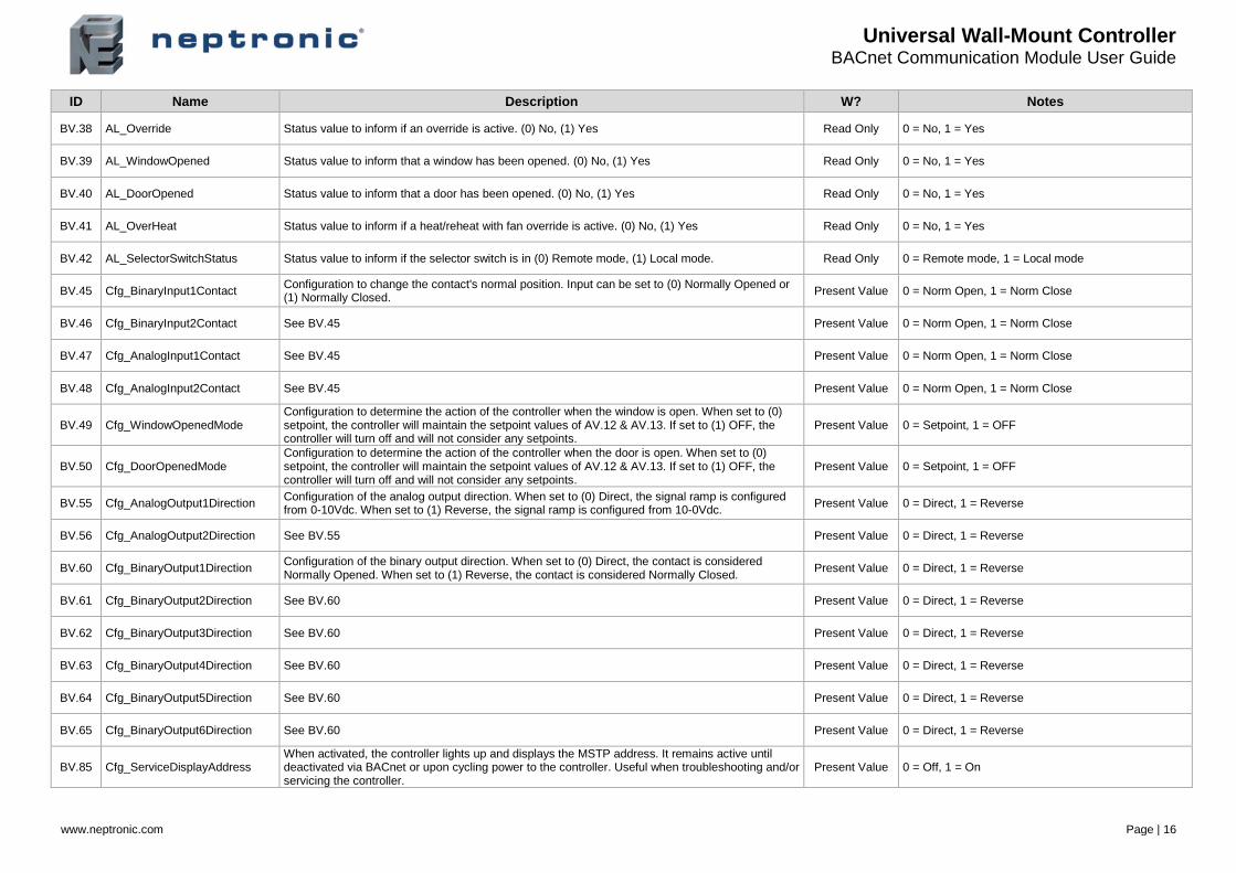
ID Name Description W? Notes
BV.38 AL_Override Status value to inform if an override is active. (0) No, (1) Yes Read Only 0 = No, 1 = Yes
BV.39 AL_WindowOpened Status value to inform that a window has been opened. (0) No, (1) Yes Read Only 0 = No, 1 = Yes
BV.40 AL_DoorOpened Status value to inform that a door has been opened. (0) No, (1) Yes Read Only 0 = No, 1 = Yes
BV.41 AL_OverHeat Status value to inform if a heat/reheat with fan override is active. (0) No, (1) Yes Read Only 0 = No, 1 = Yes
BV.42 AL_SelectorSwitchStatus Status value to inform if the selector switch is in (0) Remote mode, (1) Local mode. Read Only 0 = Remote mode, 1 = Local mode
BV.45 Cfg_BinaryInput1Contact Configuration to change the contact's normal position. Input can be set to (0) Normally Opened or (1) Normally Closed.
Present Value 0 = Norm Open, 1 = Norm Close
BV.46 Cfg_BinaryInput2Contact See BV.45 Present Value 0 = Norm Open, 1 = Norm Close
BV.47 Cfg_AnalogInput1Contact See BV.45 Present Value 0 = Norm Open, 1 = Norm Close
BV.48 Cfg_AnalogInput2Contact See BV.45 Present Value 0 = Norm Open, 1 = Norm Close
BV.49 Cfg_WindowOpenedMode Configuration to determine the action of the controller when the window is open. When set to (0) setpoint, the controller will maintain the setpoint values of AV.12 & AV.13. If set to (1) OFF, the controller will turn off and will not consider any setpoints.
Present Value 0 = Setpoint, 1 = OFF
BV.50 Cfg_DoorOpenedMode Configuration to determine the action of the controller when the door is open. When set to (0) setpoint, the controller will maintain the setpoint values of AV.12 & AV.13. If set to (1) OFF, the controller will turn off and will not consider any setpoints.
Present Value 0 = Setpoint, 1 = OFF
BV.55 Cfg_AnalogOutput1Direction Configuration of the analog output direction. When set to (0) Direct, the signal ramp is configured from 0-10Vdc. When set to (1) Reverse, the signal ramp is configured from 10-0Vdc.
Present Value 0 = Direct, 1 = Reverse
BV.56 Cfg_AnalogOutput2Direction See BV.55 Present Value 0 = Direct, 1 = Reverse
BV.60 Cfg_BinaryOutput1Direction Configuration of the binary output direction. When set to (0) Direct, the contact is considered Normally Opened. When set to (1) Reverse, the contact is considered Normally Closed.
Present Value 0 = Direct, 1 = Reverse
BV.61 Cfg_BinaryOutput2Direction See BV.60 Present Value 0 = Direct, 1 = Reverse
BV.62 Cfg_BinaryOutput3Direction See BV.60 Present Value 0 = Direct, 1 = Reverse
BV.63 Cfg_BinaryOutput4Direction See BV.60 Present Value 0 = Direct, 1 = Reverse
BV.64 Cfg_BinaryOutput5Direction See BV.60 Present Value 0 = Direct, 1 = Reverse
BV.65 Cfg_BinaryOutput6Direction See BV.60 Present Value 0 = Direct, 1 = Reverse
BV.85 Cfg_ServiceDisplayAddress When activated, the controller lights up and displays the MSTP address. It remains active until deactivated via BACnet or upon cycling power to the controller. Useful when troubleshooting and/or servicing the controller.
Present Value 0 = Off, 1 = On
Universal Wall-Mount Controller BACnet Communication Module User Guide
www.neptronic.com Page | 17
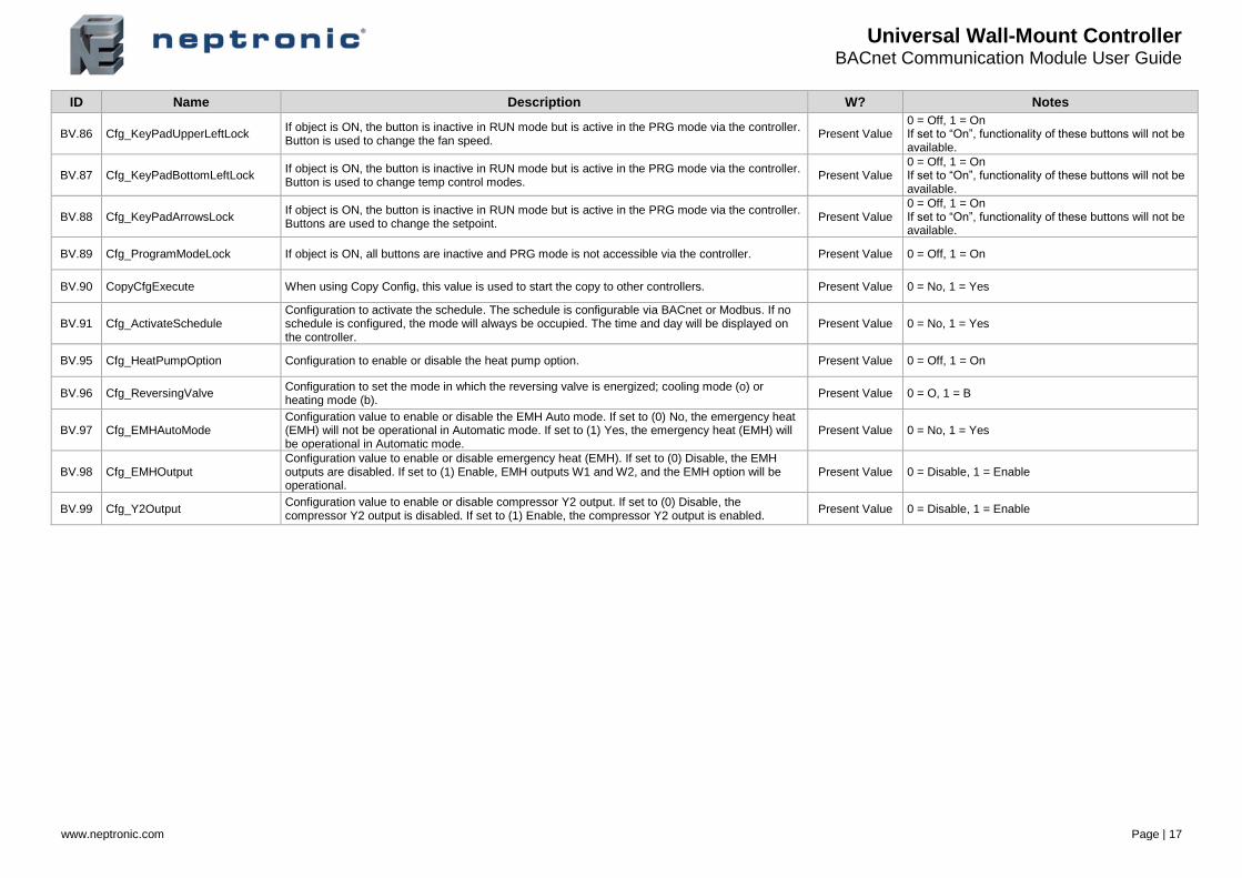
ID Name Description W? Notes
BV.86 Cfg_KeyPadUpperLeftLock If object is ON, the button is inactive in RUN mode but is active in the PRG mode via the controller. Button is used to change the fan speed.
Present Value 0 = Off, 1 = On If set to “On”, functionality of these buttons will not be available.
BV.87 Cfg_KeyPadBottomLeftLock If object is ON, the button is inactive in RUN mode but is active in the PRG mode via the controller. Button is used to change temp control modes.
Present Value 0 = Off, 1 = On If set to “On”, functionality of these buttons will not be available.
BV.88 Cfg_KeyPadArrowsLock If object is ON, the button is inactive in RUN mode but is active in the PRG mode via the controller. Buttons are used to change the setpoint.
Present Value 0 = Off, 1 = On If set to “On”, functionality of these buttons will not be available.
BV.89 Cfg_ProgramModeLock If object is ON, all buttons are inactive and PRG mode is not accessible via the controller. Present Value 0 = Off, 1 = On
BV.90 CopyCfgExecute When using Copy Config, this value is used to start the copy to other controllers. Present Value 0 = No, 1 = Yes
BV.91 Cfg_ActivateSchedule Configuration to activate the schedule. The schedule is configurable via BACnet or Modbus. If no schedule is configured, the mode will always be occupied. The time and day will be displayed on the controller.
Present Value 0 = No, 1 = Yes
BV.95 Cfg_HeatPumpOption Configuration to enable or disable the heat pump option. Present Value 0 = Off, 1 = On
BV.96 Cfg_ReversingValve Configuration to set the mode in which the reversing valve is energized; cooling mode (o) or heating mode (b).
Present Value 0 = O, 1 = B
BV.97 Cfg_EMHAutoMode Configuration value to enable or disable the EMH Auto mode. If set to (0) No, the emergency heat (EMH) will not be operational in Automatic mode. If set to (1) Yes, the emergency heat (EMH) will be operational in Automatic mode.
Present Value 0 = No, 1 = Yes
BV.98 Cfg_EMHOutput Configuration value to enable or disable emergency heat (EMH). If set to (0) Disable, the EMH outputs are disabled. If set to (1) Enable, EMH outputs W1 and W2, and the EMH option will be operational.
Present Value 0 = Disable, 1 = Enable
BV.99 Cfg_Y2Output Configuration value to enable or disable compressor Y2 output. If set to (0) Disable, the compressor Y2 output is disabled. If set to (1) Enable, the compressor Y2 output is enabled.
Present Value 0 = Disable, 1 = Enable
Universal Wall-Mount Controller BACnet Communication Module User Guide
www.neptronic.com Page | 18
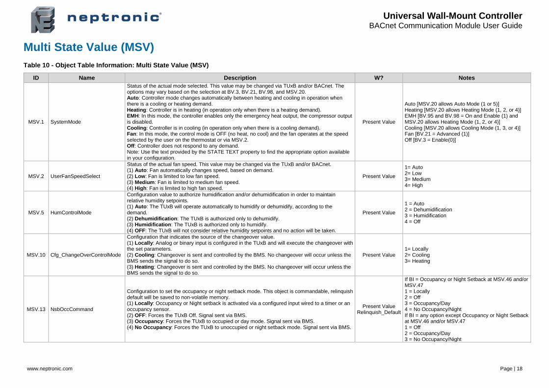
Multi State Value (MSV)
Table 10 - Object Table Information: Multi State Value (MSV)
ID Name Description W? Notes
MSV.1 SystemMode
Status of the actual mode selected. This value may be changed via TUxB and/or BACnet. The options may vary based on the selection at BV.3, BV.21, BV.98, and MSV.20. Auto: Controller mode changes automatically between heating and cooling in operation when there is a cooling or heating demand. Heating: Controller is in heating (in operation only when there is a heating demand). EMH: In this mode, the controller enables only the emergency heat output, the compressor output is disabled. Cooling: Controller is in cooling (in operation only when there is a cooling demand). Fan: In this mode, the control mode is OFF (no heat, no cool) and the fan operates at the speed selected by the user on the thermostat or via MSV.2. Off: Controller does not respond to any demand. Note: Use the text provided by the STATE TEXT property to find the appropriate option available in your configuration.
Present Value
Auto [MSV.20 allows Auto Mode (1 or 5)] Heating [MSV.20 allows Heating Mode (1, 2, or 4)] EMH [BV.95 and BV.98 = On and Enable (1) and MSV.20 allows Heating Mode (1, 2, or 4)] Cooling [MSV.20 allows Cooling Mode (1, 3, or 4)] Fan [BV.21 = Advanced (1)] Off [BV.3 = Enable(0)]
MSV.2 UserFanSpeedSelect
Status of the actual fan speed. This value may be changed via the TUxB and/or BACnet. (1) Auto: Fan automatically changes speed, based on demand. (2) Low: Fan is limited to low fan speed. (3) Medium: Fan is limited to medium fan speed. (4) High: Fan is limited to high fan speed.
Present Value
1= Auto 2= Low 3= Medium 4= High
MSV.5 HumControlMode
Configuration value to authorize humidification and/or dehumidification in order to maintain relative humidity setpoints. (1) Auto: The TUxB will operate automatically to humidify or dehumidify, according to the demand. (2) Dehumidification: The TUxB is authorized only to dehumidify. (3) Humidification: The TUxB is authorized only to humidify. (4) OFF: The TUxB will not consider relative humidity setpoints and no action will be taken.
Present Value
1 = Auto 2 = Dehumidification 3 = Humidification 4 = Off
MSV.10 Cfg_ChangeOverControlMode
Configuration that indicates the source of the changeover value. (1) Locally: Analog or binary input is configured in the TUxB and will execute the changeover with the set parameters. (2) Cooling: Changeover is sent and controlled by the BMS. No changeover will occur unless the BMS sends the signal to do so. (3) Heating: Changeover is sent and controlled by the BMS. No changeover will occur unless the BMS sends the signal to do so.
Present Value 1= Locally 2= Cooling 3= Heating
MSV.13 NsbOccCommand
Configuration to set the occupancy or night setback mode. This object is commandable, relinquish default will be saved to non-volatile memory. (1) Locally: Occupancy or Night setback is activated via a configured input wired to a timer or an occupancy sensor. (2) OFF: Forces the TUxB Off. Signal sent via BMS. (3) Occupancy: Forces the TUxB to occupied or day mode. Signal sent via BMS. (4) No Occupancy: Forces the TUxB to unoccupied or night setback mode. Signal sent via BMS.
Present Value Relinquish_Default
If BI = Occupancy or Night Setback at MSV.46 and/or MSV.47 1 = Locally 2 = Off 3 = Occupancy/Day 4 = No Occupancy/Night If BI = any option except Occupancy or Night Setback at MSV.46 and/or MSV.47 1 = Off 2 = Occupancy/Day 3 = No Occupancy/Night
Universal Wall-Mount Controller BACnet Communication Module User Guide
www.neptronic.com Page | 19
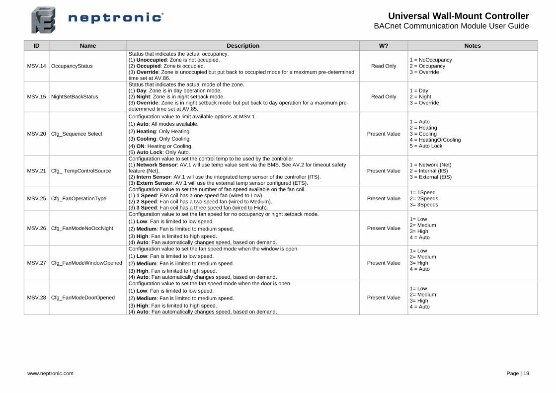
ID Name Description W? Notes
MSV.14 OccupancyStatus
Status that indicates the actual occupancy. (1) Unoccupied: Zone is not occupied. (2) Occupied: Zone is occupied. (3) Override: Zone is unoccupied but put back to occupied mode for a maximum pre-determined time set at AV.86.
Read Only 1 = NoOccupancy 2 = Occupancy 3 = Override
MSV.15 NightSetBackStatus
Status that indicates the actual mode of the zone. (1) Day: Zone is in day operation mode. (2) Night: Zone is in night setback mode. (3) Override: Zone is in night setback mode but put back to day operation for a maximum pre-determined time set at AV.85.
Read Only 1 = Day 2 = Night 3 = Override
MSV.20 Cfg_Sequence Select
Configuration value to limit available options at MSV.1.
(1) Auto: All modes available.
(2) Heating: Only Heating.
(3) Cooling: Only Cooling.
(4) ON: Heating or Cooling. (5) Auto Lock: Only Auto.
Present Value
1 = Auto 2 = Heating 3 = Cooling 4 = HeatingOrCooling 5 = Auto Lock
MSV.21 Cfg_ TempControlSource
Configuration value to set the control temp to be used by the controller. (1) Network Sensor: AV.1 will use temp value sent via the BMS. See AV.2 for timeout safety feature (Net). (2) Intern Sensor: AV.1 will use the integrated temp sensor of the controller (ITS). (3) Extern Sensor: AV.1 will use the external temp sensor configured (ETS).
Present Value 1 = Network (Net) 2 = Internal (ItS) 3 = External (EtS)
MSV.25 Cfg_FanOperationType
Configuration value to set the number of fan speed available on the fan coil. (1) 1 Speed: Fan coil has a one speed fan (wired to Low). (2) 2 Speed: Fan coil has a two speed fan (wired to Medium). (3) 3 Speed: Fan coil has a three speed fan (wired to High).
Present Value 1= 1Speed 2= 2Speeds 3= 3Speeds
MSV.26 Cfg_FanModeNoOccNight
Configuration value to set the fan speed for no occupancy or night setback mode.
(1) Low: Fan is limited to low speed.
(2) Medium: Fan is limited to medium speed.
(3) High: Fan is limited to high speed. (4) Auto: Fan automatically changes speed, based on demand.
Present Value
1= Low 2= Medium 3= High 4 = Auto
MSV.27 Cfg_FanModeWindowOpened
Configuration value to set the fan speed mode when the window is open.
(1) Low: Fan is limited to low speed.
(2) Medium: Fan is limited to medium speed.
(3) High: Fan is limited to high speed. (4) Auto: Fan automatically changes speed, based on demand.
Present Value
1= Low 2= Medium 3= High 4 = Auto
MSV.28 Cfg_FanModeDoorOpened
Configuration value to set the fan speed mode when the door is open.
(1) Low: Fan is limited to low speed.
(2) Medium: Fan is limited to medium speed.
(3) High: Fan is limited to high speed. (4) Auto: Fan automatically changes speed, based on demand.
Present Value
1= Low 2= Medium 3= High 4 = Auto
Universal Wall-Mount Controller BACnet Communication Module User Guide
www.neptronic.com Page | 20
ID Name Description W? Notes
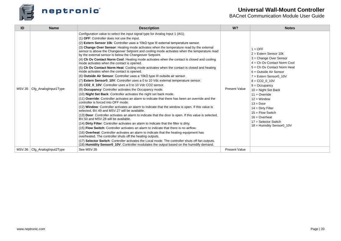
MSV.35 Cfg_AnalogInput1Type
Configuration value to select the input signal type for Analog Input 1 (AI1).
(1) OFF: Controller does not use the input.
(2) Extern Sensor 10k: Controller uses a 10kΩ type III external temperature sensor.
(3) Change Over Sensor: Heating mode activates when the temperature read by the external sensor is above the Changeover Setpoint and cooling mode activates when the temperature read by the external sensor is below the Changeover Setpoint.
(4) Ch Ov Contact Norm Cool: Heating mode activates when the contact is closed and cooling mode activates when the contact is opened.
(5) Ch Ov Contact Norm Heat: Cooling mode activates when the contact is closed and heating mode activates when the contact is opened.
(6) Outside Air Sensor: Controller uses a 10kΩ type III outside air sensor.
(7) Extern Sensor0_10V: Controller uses a 0 to 10 Vdc external temperature sensor.
(8) CO2_0_10V: Controller uses a 0 to 10 Vdc CO2 sensor.
(9) Occupancy: Controller activates the Occupancy mode.
(10) Night Set Back: Controller activates the night set back mode.
(11) Override: Controller activates an alarm to indicate that there has been an override and the controller is forced into OFF mode.
(12) Window: Controller activates an alarm to indicate that the window is open. If this value is selected, BV.49 and MSV.27 will be available.
(13) Door: Controller activates an alarm to indicate that the door is open. If this value is selected, BV.50 and MSV.28 will be available.
(14) Dirty Filter: Controller activates an alarm to indicate that the filter is dirty.
(15) Flow Switch: Controller activates an alarm to indicate that there is no airflow.
(16) Overheat: Controller activates an alarm to indicate that the heating equipment has overheated. The controller shuts off the heating outputs.
(17) Selector Switch: Controller activates the Local mode. The controller shuts off fan outputs. (18) Humidity Sensor0_10V: Controller modulates the output based on the humidify demand.
Present Value
1 = OFF
2 = Extern Sensor 10k
3 = Change Over Sensor
4 = Ch Ov Contact Norm Cool
5 = Ch Ov Contact Norm Heat
6 = Outside Air Sensor
7 = Extern Sensor0_10V
8 = CO2_0_10V
9 = Occupancy
10 = Night Set Back
11 = Override
12 = Window
13 = Door
14 = Dirty Filter
15 = Flow Switch
16 = Overheat
17 = Selector Switch 18 = Humidity Sensor0_10V
MSV.36 Cfg_AnalogInput2Type See MSV.35 Present Value

Universal Wall-Mount Controller BACnet Communication Module User Guide
www.neptronic.com Page | 21
ID Name Description W? Notes
MSV.46 Cfg_BinaryInput1Type
Configuration value to select the input signal type for Binary Input 1 (BI1).
(1) OFF: Controller does not use the input
(2) Override: Controller activates an alarm to indicate that there has been an override and the controller is forced into OFF mode.
(3) Window: Controller activates an alarm to indicate that the window is open. If this value is selected, BV.49 and MSV.27 will be available.
(4) Door: Controller activates an alarm to indicate that the door is open. If this value is selected, BV.50 and MSV.28 will be available.
(5) Dirty Filter: Controller activates an alarm to indicate that the filter is dirty.
(6) Flow Switch: Controller activates an alarm to indicate that there is no airflow.
(7) Overheat: Controller activates an alarm to indicate that the heating equipment has overheated. The controller shuts off the heating outputs.
(8) Selector Switch: Controller activates the Local mode. The controller shuts off fan outputs.
(9) Ch Ov Contact Norm Cool: Heating mode activates when the contact is closed and cooling mode activates when the contact is opened.
(10) Ch Ov Contact Norm Heat: Cooling mode activates when the contact is closed and heating mode activates when the contact is opened.
(11) Occupancy: Controller activates the Occupancy mode. (12) Night Set Back: Controller activates the night set back mode.
Present Value
(1) = OFF
(2) = Override
(3) = Window
(4) = Door
(5) = Dirty Filter
(6) = Flow Switch
(7) = Overheat
(8) = Selector Switch
(9) = Ch Ov Contact Norm Cool
(10) = Ch Ov Contact Norm Heat
(11) = Occupancy (12) = Night Set Back
MSV.47 Cfg_BinaryInput2Type See MSV.46 Present Value
MSV.55 Cfg_AnalogOutput1Ramp
Configuration of the ramp used to modulate AO1 based on demand.
(1) OFF: The controller does not use the output.
(2) Change Over With Fan: The controller modulates heating and cooling, as appropriate.
(3) Cooling1 With Fan: This ramp is used for cooling. The controller performs cooling based on the cooling proportional, integral, and dead band values.
(4) Cooling2 With Fan: This ramp is used for cooling. The controller performs cooling based on the cooling proportional, integral, and dead band values.
(5) Heating1 With Fan: This ramp is used for heating. The controller performs heating based on the heating proportional, integral, and dead band values.
(6) Heating2 With Fan: This ramp is used for heating. The controller performs heating based on the heating proportional, integral, and dead band values.
(7) Heating2: This ramp is used for heating. The controller performs heating based on the heating proportional, integral, and dead band values.
(8) Cooling1 Heating1 With Fan: The controller performs cooling regularly. If another output is set to heat, it performs heating regularly.
(9) HumidifyWithFan: The controller modulates the output based on the humidify demand.
(10) CO2 Alarm: Carbon dioxide (CO2) alarm. The controller activates or deactivates the output based on carbon dioxide levels.
(11) 6 way valve: The controller modulates the 6-way valve based on the heating or cooling demand.
Present Value
1 = OFF
2 = Change Over With Fan
3 = Cooling1 With Fan
4 = Cooling2 With Fan
5 = Heating1 With Fan
6 = Heating2 With Fan
7 = Heating2
8 = Cooling1 Heating1 With Fan
9 = HumidifyWithFan 10 = CO2 Alarm 11 = 6 way valve
MSV.57 Cfg_AnalogOutput2Ramp
See MSV.55
If BV.95 Cfg_HeatPumpOption is set to Off, AO2 has an additional option: (12) Fan: The controller modulates the output according to AV. 60 Fan Demand.
Present Value
Universal Wall-Mount Controller BACnet Communication Module User Guide
www.neptronic.com Page | 22
ID Name Description W? Notes
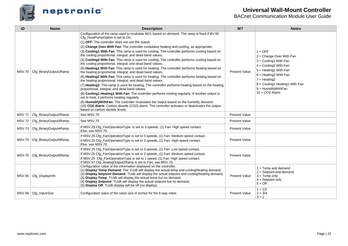
MSV.70 Cfg_BinaryOutput1Ramp
Configuration of the ramp used to modulate BO1 based on demand. The ramp is fixed if BV.95 Cfg_HeatPumpOption is set to On.
(1) OFF: The controller does not use the output.
(2) Change Over With Fan: The controller modulates heating and cooling, as appropriate.
(3) Cooling1 With Fan: This ramp is used for cooling. The controller performs cooling based on the cooling proportional, integral, and dead band values.
(4) Cooling2 With Fan: This ramp is used for cooling. The controller performs cooling based on the cooling proportional, integral, and dead band values.
(5) Heating1 With Fan: This ramp is used for heating. The controller performs heating based on the heating proportional, integral, and dead band values.
(6) Heating2 With Fan: This ramp is used for heating. The controller performs heating based on the heating proportional, integral, and dead band values.
(7) Heating2: This ramp is used for heating. The controller performs heating based on the heating proportional, integral, and dead band values.
(8) Cooling1 Heating1 With Fan: The controller performs cooling regularly. If another output is set to heat, it performs heating regularly.
(9) HumidifyWithFan: The controller modulates the output based on the humidify demand. (10) CO2 Alarm: Carbon dioxide (CO2) alarm. The controller activates or deactivates the output based on carbon dioxide levels.
Present Value
1 = OFF
2 = Change Over With Fan
3 = Cooling1 With Fan
4 = Cooling2 With Fan
5 = Heating1 With Fan
6 = Heating2 With Fan
7 = Heating2
8 = Cooling1 Heating1 With Fan
9 = HumidifyWithFan 10 = CO2 Alarm
MSV.71 Cfg_BinaryOutput2Ramp See MSV.70 Present Value
MSV.72 Cfg_BinaryOutput3Ramp See MSV.70 Present Value
MSV.73 Cfg_BinaryOutput4Ramp If MSV.25 Cfg_FanOperationType is set to 3 speeds, (1) Fan: High speed contact. Else, see MSV.70.
Present Value
MSV.74 Cfg_BinaryOutput5Ramp If MSV.25 Cfg_FanOperationType is set to 3 speeds, (1) Fan: Medium speed contact.
If MSV.25 Cfg_FanOperationType is set to 2 speeds, (1) Fan: High speed contact. Else, see MSV.70.
Present Value
MSV.75 Cfg_BinaryOutput6Ramp
If MSV.25 Cfg_FanOperationType is set to 3 speeds, (1) Fan: Low speed contact.
If MSV.25 Cfg_FanOperationType is set to 2 speeds, (1) Fan: Medium speed contact.
If MSV.25 Cfg_FanOperationType is set to 1 speed, (1) Fan: High speed contact. If MSV.57 Cfg_AnalogOutput2Ramp is set to Fan, see MSV.70.
Present Value
MSV.95 Cfg_DisplayInfo
Configuration value of the information displayed on the controller. (1) Display Temp Demand: The TUxB will display the actual temp and cooling/heating demand. (2) Display Setpoint Demand: TUxB will display the actual setpoint and cooling/heating demand. (3) Display Temp: TUxB will display the actual temp but no demand. (4) Display Setpoint: TUxB will display the actual setpoint but no demand. (5) Display Off: TUxB display will be off (no display).
Present Value
1 = Temp and demand 2 = Setpoint and demand 3 = Temp only 4 = Setpoint only 5 = Off
MSV.96 Cfg_ValveSize Configuration value of the valve size in inches for the 6-way valve. Present Value 1 = 1/2 2 = 3/4 3 = 1
Universal Wall-Mount Controller BACnet Communication Module User Guide
www.neptronic.com Page | 23
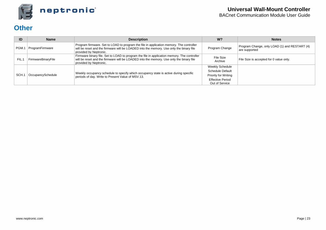
Other
ID Name Description W? Notes
PGM.1 ProgramFirmware Program firmware. Set to LOAD to program the file in application memory. The controller will be reset and the firmware will be LOADED into the memory. Use only the binary file provided by Neptronic.
Program Change Program Change, only LOAD (1) and RESTART (4) are supported
FIL.1 FirmwareBinaryFile Firmware binary file. Set to LOAD to program the file in application memory. The controller will be reset and the firmware will be LOADED into the memory. Use only the binary file provided by Neptronic.
File Size Archive
File Size is accepted for 0 value only.
SCH.1 OccupancySchedule Weekly occupancy schedule to specify which occupancy state is active during specific periods of day. Write to Present Value of MSV.13.
Weekly Schedule
Schedule Default
Priority for Writing
Effective Period Out of Service

Notes


400 Lebeau blvd, Montreal, Qc, H4N 1R6, Canada
www.neptronic.com
Toll free in North America: 1-800-361-2308
Tel.: (514) 333-1433
Fax: (514) 333-3163
Customer service fax: (514) 333-1091
Monday to Friday: 8:00am to 5:00pm (Eastern time)