
Universal Pump Controller (UPC-GEO) by Grundfos · Universal Pump Controller (UPC-GEO) by Grundfos...
36
Universal Pump Controller (UPC-GEO) by Grundfos WARNING: Improper installation, setup, modification, operation or maintenance of the heating system can cause personal injury and property damage. Follow each appliances' instructions precisely. For assistance or further information, contact a trained and certified installer or service provider. Application drawings in this manual are conceptual only and do not purport to address all design, installation, code, or safety considerations. The diagrams in this manual are for reference use by code officials, designers and licensed installers. It is expected that installers have adequate knowledge of national and local codes, as well as accepted industry practices, and are trained on equipment, procedures, and applications involved. Drawings are not to scale. Installation and Operating Manual
Transcript of Universal Pump Controller (UPC-GEO) by Grundfos · Universal Pump Controller (UPC-GEO) by Grundfos...

Universal Pump Controller (UPC-GEO) by Grundfos
WARNING:Improper installation, setup, modifi cation, operation ormaintenance of the heating system can cause personalinjury and property damage.Follow each appliances' instructions precisely.For assistance or further information, contact a trained and certifi ed installer or service provider.
Application drawings in this manual are conceptual only and do not purport to address all design, installation, code, or safety considerations.
The diagrams in this manual are for reference use by code offi cials, designers and licensed installers. It is expected that installers have adequate knowledge of national and local codes, as well as accepted industry practices, and are trained on equipment, procedures, and applications involved. Drawings are not to scale.
Installation and Operating Manual

Bosch Flo-Link™ Pressurized Flow Centers Installation, Operating & Maintenance Manual
Bosch Thermotechnology Corp.Data subject to change
Setup (con’d) . . . . . . . . . . . . . . . . . . . . . Setup Menu. . . . . . . . . . . . . . . . . . . 12 Flow Confi gura on . . . . . . . . . . . . . . . . 12 ∆T Confi gura on . . . . . . . . . . . . . . . . . 13 Sensor Confi gura on . . . . . . . . . . . . . . . 13 Media Confi gura on . . . . . . . . . . . . . . . 14 Mode Setup. . . . . . . . . . . . . . . . . . . 14 Lockout Setup . . . . . . . . . . . . . . . . . . 14 Controller Output Signal Setup. . . . . . . . . . . 15Troubleshoo ng. . . . . . . . . . . . . . . . . . . 16Appendix A: Sensor Kit Descrip ons . . . . . . . . . . 17Appendix B: Installing Sensors . . . . . . . . . . . . . 20Appendix C: Important Power Considera ons . . . . . . 21Appendix D: Controller Moun ng Template . . . . . . . 22Appendix E1: Pressurized Var. Spd. Flow Center Submi als . . . . . . 23Appendix E2: Non-press. Var. Spd. Flow Center Submi als . . . . . . . 24
Appendix F: An freeze Fluid Factors . . . . . . . . . . 30
Table of Contents General Descrip on . . . . . . . . . . . . . . . . . 1 Overview . . . . . . . . . . . . . . . . . . . . 1 Flow Rate Based Control . . . . . . . . . . . . . 1 ∆T Based Control . . . . . . . . . . . . . . . . 2Technical Specifi ca ons . . . . . . . . . . . . . . . 2Agency Lis ng/Approvals . . . . . . . . . . . . . . . 3Dimensional Data . . . . . . . . . . . . . . . . . . 3Installa on . . . . . . . . . . . . . . . . . . . . . 4 Loca on . . . . . . . . . . . . . . . . . . . . 4 Tools Required . . . . . . . . . . . . . . . . . . 4 Legend of Abbrevia ons . . . . . . . . . . . . . 4 Moun ng . . . . . . . . . . . . . . . . . . . . 4 Wiring (Single Unit -- Magna GEO Pump) . . . . . . 5 Wiring (One Flow Center/Two Heat Pumps) . . . . . 8 Wiring (0-10 VDC output) . . . . . . . . . . . . . 10Setup . . . . . . . . . . . . . . . . . . . . . . . 11 Quick Start Procedure . . . . . . . . . . . . . . 11 General Naviga on . . . . . . . . . . . . . . . . 11 Main Page . . . . . . . . . . . . . . . . . . . 11 System Status . . . . . . . . . . . . . . . . . . 12
Notes:
This guide provides the installer with instruc ons specifi c to Grundfos Universal Pump Controller (UPC-GEO). Please refer to your heat pump manufacturer’s instruc ons or IGSHPA guidelines for addi onal detailed fl ushing, purging, and installa on informa on. Please review the en re IOM document before proceeding with the installa on.
Bosch Thermotechnology Corp. makes no warranty or representa on, expressed or implied, with respect to the accuracy, completeness, or usefulness of this informa on, nor assumes any liability with respect to the use of any informa on con-tained within this document.
Explana on of SymbolsWarnings
Warnings in this document are identifi ed by a warning triangle printed against a grey background.Keywords at the start of a warning indicate the type and seriousness of the ensuing risk if measures to prevent the risk are not taken.
The following keywords are defi ned and can be used in this document: DANGER indicates a hazardous situa on which, if not avoided, will result in death or serious injury.
WARNING indicates a hazardous situation which, if not avoided, could result in death or serious injury.
CAUTION indicates a hazardous situa on which, if not avoided, could result in minor to moderate injury.
NOTICE is used to address prac ces not related to personal injury.
Important informa on
This symbol indicates important informa on wherethere is no risk to people or property.

Installation, Operating & Maintenance Manual Universal Pump Controller (UPC-GEO) by Grundfos | 1
Bosch Thermotechnology Corp. Data subject to change
General Descrip on
Overview
Flo-Link™ is a trademark of Geo-Flo Products Corpora on, Bedford, IN, U.S.A. The Universal Pump Controller (UPC-GEO), designed in collabora on with Grundfos, is a 24VAC powered controller that operates a one- or two-pump variable speed flow center system to provide accurate pump control and feedback resul ng in the lowest possible power consump on for the pump(s) and system (PWM output only; feedback not available for 0-10 VDC output). Instantaneous pump power in Wa s is displayed on the back-lit LCD (PWM output only) along with other system parameters depending on which sensors are installed. The installa on technician decides whether to control the pump speed based on flow rate set points or differen al temperature (∆T) set points. Installing a single Grundfos Vortex Flow Sensor (VFS) with the UPC- GEO allows the system to be controlled using a flow rate set point input into the controller based on the requirements of the heat pump. The controller allows separate flow rate inputs for two-speed heat pumps, which results in substan al energy savings due to lower flow rate requirements in first-stage heat pump opera on. The Grundfos Vortex Flow Sensor provides both flow rate and temperature feedback which is displayed on the controller. Diff eren al temperature (ΔT) control requires the addi on of two immersion thermistors and allows separate ΔT inputs for hea ng and cooling modes. Installing both a VFS sensor and thermistors allows the UPC-GEO to display flow rate, ΔT, and heat of extrac on/rejec on in KBTU/H. Two lockout modes allow the installer to choose whether to lock the system parameters so they cannot be inadvertently changed or to lock the screen so the feedback (temperatures, flow rate, power, etc.) are not displayed. A Meter mode is included which allows the UPC-GEO to display temperature, flow, and MBtu parameters but does not control the pump(s).
Flow-rate based control (Grundfos VFS flow sensor required)
The UPC-GEO receives a 24VAC signal from the heat pump or thermostat for stage-one or stage-two hea ng or cooling. The UPC-GEO then provides a PWM signal to the variable speed Magna GEO 32-140 pump (or 0-10 VDC output for other pumps) and monitors the output signal from the Grundfos VFS flow sensor and pump. The UPC-GEO increases or decreases the pump speed based on the flow rate input into the controller and the actual flow rate of the system. For higher flow rate and/or head loss systems a two-pump variable speed flow center may be required. This flow center consists of a single variable speed Magna GEO 32-140 and a constant speed UPS26-99. The UPC-GEO a empts to sa sfy the flow rate requirement by first using the more efficient Magna GEO 32-140 pump. If the Magna GEO reaches its maximum performance level before sa sfying the flow rate set point requirement, the UPC-GEO energizes the UPS26-99 and ramps the Magna GEO down to match the requirement, thereby minimizing pumping power. The UPC-GEO saves the pump signal se ngs to allow it to quickly deliver the required flow rate on subsequent calls for hea ng or cooling. On two-pump variable speed flow center systems the UPC-GEO energizes the UP26-99 for 30 seconds every 72 hours if it has not run during that same period.
2 | Universal Pump Controller (UPC-GEO) by Grundfos Installation, Operating & Maintenance Manual
Bosch Thermotechnology Corp.Data subject to change
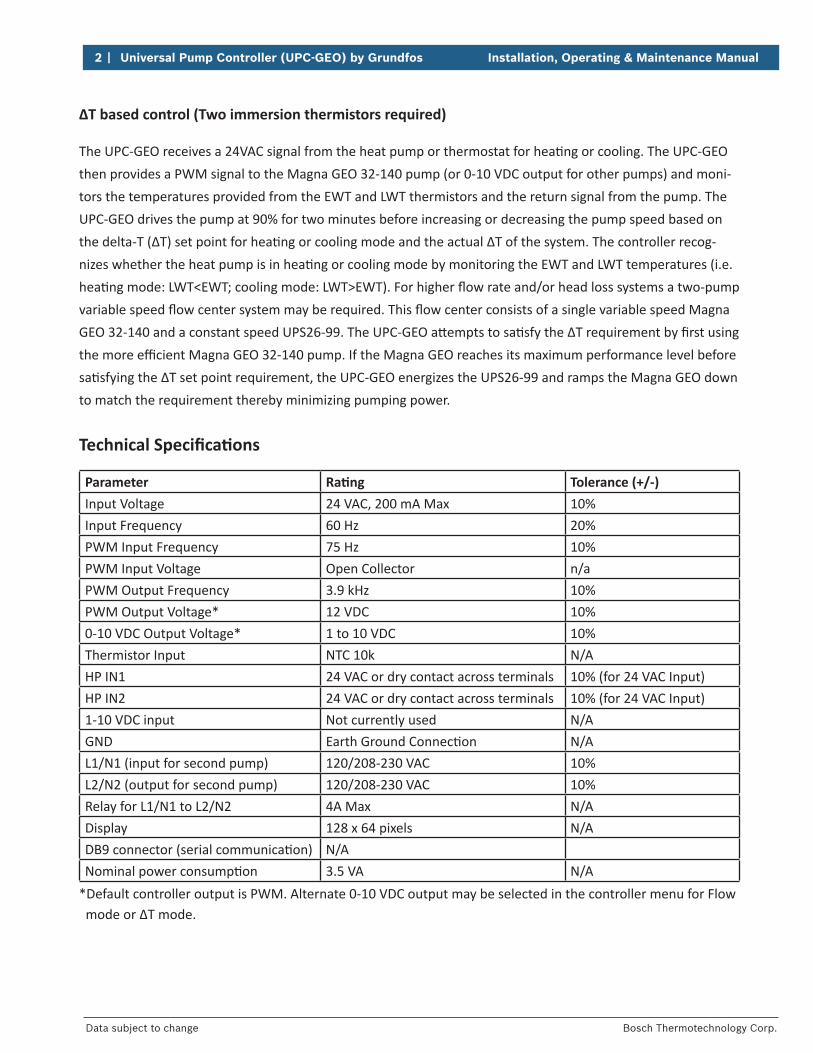
ΔT based control (Two immersion thermistors required)
The UPC-GEO receives a 24VAC signal from the heat pump or thermostat for hea ng or cooling. The UPC-GEO then provides a PWM signal to the Magna GEO 32-140 pump (or 0-10 VDC output for other pumps) and moni-tors the temperatures provided from the EWT and LWT thermistors and the return signal from the pump. The UPC-GEO drives the pump at 90% for two minutes before increasing or decreasing the pump speed based on the delta-T (ΔT) set point for hea ng or cooling mode and the actual ΔT of the system. The controller recog-nizes whether the heat pump is in hea ng or cooling mode by monitoring the EWT and LWT temperatures (i.e. hea ng mode: LWT<EWT; cooling mode: LWT>EWT). For higher fl ow rate and/or head loss systems a two-pump variable speed fl ow center system may be required. This fl ow center consists of a single variable speed Magna GEO 32-140 and a constant speed UPS26-99. The UPC-GEO a empts to sa sfy the ΔT requirement by fi rst using the more effi cient Magna GEO 32-140 pump. If the Magna GEO reaches its maximum performance level before sa sfying the ΔT set point requirement, the UPC-GEO energizes the UPS26-99 and ramps the Magna GEO down to match the requirement thereby minimizing pumping power.
Technical Specifi ca ons
Parameter Ra ng Tolerance (+/-)Input Voltage 24 VAC, 200 mA Max 10%Input Frequency 60 Hz 20%PWM Input Frequency 75 Hz 10%PWM Input Voltage Open Collector n/aPWM Output Frequency 3.9 kHz 10%PWM Output Voltage* 12 VDC 10%0-10 VDC Output Voltage* 1 to 10 VDC 10%Thermistor Input NTC 10k N/AHP IN1 24 VAC or dry contact across terminals 10% (for 24 VAC Input)HP IN2 24 VAC or dry contact across terminals 10% (for 24 VAC Input)1-10 VDC input Not currently used N/AGND Earth Ground Connec on N/AL1/N1 (input for second pump) 120/208-230 VAC 10%L2/N2 (output for second pump) 120/208-230 VAC 10%Relay for L1/N1 to L2/N2 4A Max N/ADisplay 128 x 64 pixels N/ADB9 connector (serial communica on) N/ANominal power consump on 3.5 VA N/A
*Default controller output is PWM. Alternate 0-10 VDC output may be selected in the controller menu for Flow mode or ∆T mode.

Installation, Operating & Maintenance Manual Universal Pump Controller (UPC-GEO) by Grundfos | 3
Bosch Thermotechnology Corp. Data subject to change
Agency Lis ngs/Approvals
Cer fi ed to CSA C22.2 No 24
Conforms to UL Standard 873
Dimensional Data
A B C D E F G H I J Weight
Inches 5-1/8 6-11/16 1-7/8 3-3/8 5-5/8 3-3/8 1-11/16 Φ1/4 Φ3/16 1/2” standard conduit
knockout
LBS KG
CM 13 17 4.7 8.6 14.3 8.6 4.3 Φ0.7 Φ0.4 0.75 0.34

4 | Universal Pump Controller (UPC-GEO) by Grundfos Installation, Operating & Maintenance Manual
Bosch Thermotechnology Corp.Data subject to change
Installa on
Loca on
The UPC-GEO can be mounted in any available indoor climate controlled loca on in or around the mechani-cal room near the variable speed pump or fl ow center. All UPC-GEO kits include moun ng hardware and a ten foot cable that allows the controller to be connected to the Grundfos Magna pump. This equipment should be installed and serviced by qualifi ed personnel only.
Please review the en re Installa on Instruc ons document before proceeding with installa on.
Tools Required
No 2 Philips Screwdriver3/16” Flathead ScrewdriverDrill3/16” Drill bitHammerSmall Philips or fl athead screwdriverWire cu ers/strippersElectrical Tape
Legend of Abbrevia ons
EWT Entering Water Temperature (from loop to heat pump)
LWT Leaving Water Temperature (to loop from heat pump)
PWM Pulse Width Modula onBRN BrownBLK BlackBLU BlueHP IN# Heat Pump Input # (used for Stage # call)THERMS ThermistorsC CommonGND Earth GroundL LineN NeutralKBTU/H 1000 BTU per hour
Moun ng the Controller
1. Using the template included in Appendix C, mark the moun ng hole loca ons and install the plas c wall anchors (if necessary).
2. Remove the controller’s wiring cover by releasing its tabs with a 3/16” fl athead screwdriver as shown in Figure 1.
3. Install the upper #6 screw and slide the controller into place. Install the second screw to secure the controller to the wall.
Figure 1: Moun ng Controller
Installation, Operating & Maintenance Manual Universal Pump Controller (UPC-GEO) by Grundfos | 5
Bosch Thermotechnology Corp. Data subject to change
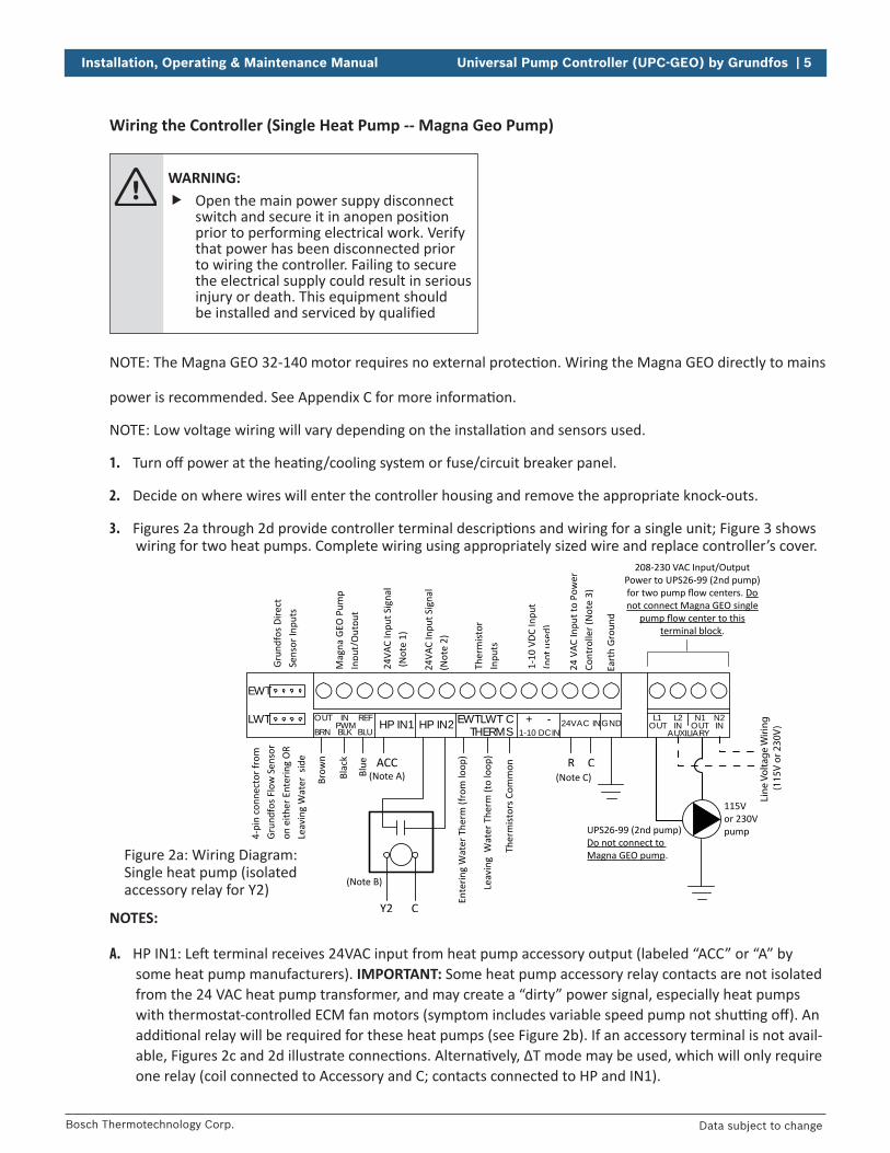
Wiring the Controller (Single Heat Pump -- Magna Geo Pump)
WARNING: Open the main power suppy disconnect
switch and secure it in anopen position prior to performing electrical work. Verify that power has been disconnected prior to wiring the controller. Failing to secure the electrical supply could result in serious injury or death. This equipment should be installed and serviced by qualified
NOTE: The Magna GEO 32-140 motor requires no external protec on. Wiring the Magna GEO directly to mains
power is recommended. See Appendix C for more informa on.
NOTE: Low voltage wiring will vary depending on the installa on and sensors used.
1. Turn off power at the hea ng/cooling system or fuse/circuit breaker panel.
2. Decide on where wires will enter the controller housing and remove the appropriate knock-outs.
3. Figures 2a through 2d provide controller terminal descrip ons and wiring for a single unit; Figure 3 shows wiring for two heat pumps. Complete wiring using appropriately sized wire and replace controller’s cover.
NOTES:
A. HP IN1: Le terminal receives 24VAC input from heat pump accessory output (labeled “ACC” or “A” by some heat pump manufacturers). IMPORTANT: Some heat pump accessory relay contacts are not isolated from the 24 VAC heat pump transformer, and may create a “dirty” power signal, especially heat pumps with thermostat-controlled ECM fan motors (symptom includes variable speed pump not shu ng off ). An addi onal relay will be required for these heat pumps (see Figure 2b). If an accessory terminal is not avail-able, Figures 2c and 2d illustrate connec ons. Alterna vely, ∆T mode may be used, which will only require one relay (coil connected to Accessory and C; contacts connected to HP and IN1).
24 V
AC In
put t
o Po
wer
Co
ntro
ller (
Not
e 3)
24VA
C In
put S
igna
l (N
ote
2)
24VA
C In
put S
igna
l (N
ote
1)
Mag
na G
EO P
ump
Inpu
t/O
utpu
t
Grun
dfos
Dire
ct
Sens
or In
puts
1-10
VDC
Inpu
t (n
otus
ed)
Eart
h Gr
ound
Ther
mist
or
Inpu
ts
Y2
Brow
n
Blac
k
Blue
Ente
ring
Wat
er T
herm
(fro
m lo
op)
Leav
ing
Wat
er T
herm
(to
loop
)
Ther
mist
ors C
omm
on
4-pi
n co
nnec
tor f
rom
Gr
undf
os F
low
Sen
sor
on e
ither
Ent
erin
g O
R Le
avin
g W
ater
sid
e R C
LWT
EWT
OUT IN REFPWM HP IN1 HP IN2 LWTEWT C
THERMS+ -
1-10 DCIN24VAC INGND
AUXILIARY
L1 L2 N1 N2OUT OUT ININ
BRN BLK BLU
ACC(Note A)
C
208-230 VAC Input/OutputPower to UPS26-99 (2nd pump)
Donot connect Magna GEO single
terminal block
Line
Vol
tage
Wiri
ng
(115
V or
230
V)
UPS26-99 (2nd pump)Do not connect to Magna GEO pump
115Vor 230Vpump
(Note B)
(Note C)
Figure 2a: Wiring Diagram: Single heat pump (isolated accessory relay for Y2)

6 | Universal Pump Controller (UPC-GEO) by Grundfos Installation, Operating & Maintenance Manual
Bosch Thermotechnology Corp.Data subject to change
B. HP IN2: Receives a contact closure from the relay connected to Y2, closing the circuit between the le and right terminals. This connec on is not required when opera ng the controller in ∆T mode. Relay is a SPST N.O. general purpose relay (equivalent to 90-360 WR/RBM Type 184).
C. 24VAC IN: Le terminal connected to “R” at heat pump; right terminal connected to “C” at heat pump.
24 V
AC In
put t
o Po
wer
Co
ntro
ller (
Not
e 3)
24VA
C In
put S
igna
l (N
ote
2)
24VA
C In
put S
igna
l (N
ote
1)
Mag
na G
EO P
ump
Inpu
t/O
utpu
t
Grun
dfos
Dire
ct
Sens
or In
puts
1-10
VDC
Inpu
t (n
otus
ed)
Eart
h Gr
ound
Ther
mist
or
Inpu
ts
Y2
Brow
n
Blac
k
Blue
Ente
ring
Wat
er T
herm
(fro
m lo
op)
Leav
ing
Wat
er T
herm
(to
loop
)
Ther
mist
ors C
omm
on
4-pi
n co
nnec
tor f
rom
Gr
undf
os F
low
Sen
sor
on e
ither
Ent
erin
g O
R Le
avin
g W
ater
sid
e R C
LWT
EWT
OUT IN REFPWM HP IN1 HP IN2 LWTEWT C
THERMS+ -
1-10 DCIN24VAC INGND
AUXILIARY
L1 L2 N1 N2OUT OUT ININ
BRN BLK BLU
(Note A)
C
208-230 VAC Input/OutputPower to UPS26-99 (2nd pump)
Donot connect Magna GEO single
terminal block
Line
Vol
tage
Wiri
ng
(115
V or
230
V)
UPS26-99 (2nd pump)Do not connect to Magna GEO pump
115Vor 230Vpump
(Note B)
(Note C)
CACC
Figure 2b: Wiring Diagram for heat pumps requiring an addi onal isola on relay -- see Notes A & B, above
Figure 2c: Wiring Diagram for heat pumps with an external compressor contactor, but without an accessory relay -- see Note A, previous page
NO
STATUS
TEST
YES
C R CCFAULT
FaultContactor
Coil
CCCompressorContactor
Coil
24 VAC
230 VAC
Use for ACCconnection*
Find an easyto accessCommon (C)connection*
*May require a “piggyback” spade connector.
NOTES:
D. Connect CC and C to isola on relay # 1 (shown as ACC and C in Figure 2b).
E. Connect Y2 and C to isola on relay #2 (shown as Y2 and C in Figure 2b).

Installation, Operating & Maintenance Manual Universal Pump Controller (UPC-GEO) by Grundfos | 7
Bosch Thermotechnology Corp. Data subject to change
Figure 2d: Wiring Diagram for heat pumps without an external compressor contactor (compressor relay is on the circuit board) and without an accessory relay -- see Note A, page 5
230VAC
230VAC
Orange* Yellow* Red*
R
SPST Relay #1 SPST Relay #2
PumpPowerBlock
C FieldSuppliedRelay(s)**(230V coil)
HPC IN1
From heat pumpcircuit board
or transformer
Field Wiring (low voltage)Field Wiring (high voltage)
R HP IN2
Not all brands have the same wire colors for the pump power block.Orange = 230 VAC (common)Yellow = 230VAC (switched) for 1st stageRed = 230VAC (switched) for 2nd stageRelay #1 needed for temperature difference mode; both relays needed for flow mode.
*
**
CAUTION: Do not connect the magna geo variable
speed pump high voltage terminals to the “t” side of the heat pump compressor contactor. The high in-rush current may cause premature contactor failure. Always connect the pump directly to the mains or to the “l” side of the compressor contactor.See appendix c for more details.
Bosch off ers a panel mount fl ow center op on for pressurized fl ow centers and a vari-able speed kit for non-pressurized fl ow centers. Both products provide factory-wired and mounted controllers, as well as factory wired thermistors and fl ow sensor (if equipped). Field low voltage wiring simply involves running 4 conductor thermostat wiring between the heat pump and the fl ow center terminal block, greatly reducing installa on me. In addi on, all components necessary for the installa on, including the hose kit, are part of the panel mount or fl ow center variable speed kit. IN
STAL
LATI
ON T
IP

8 | Universal Pump Controller (UPC-GEO) by Grundfos Installation, Operating & Maintenance Manual
Bosch Thermotechnology Corp.Data subject to change
Wiring the Controller (One Flow Center / Two Heat Pumps)
WARNING: Open the main power suppy disconnect
switch and secure it in anopen position prior to performing electrical work. Verify that power has been disconnected prior to wiring the controller. Failing to secure the electrical supply could result in serious injury or death. This equipment should be installed and serviced by qualified
NOTE: The Magna GEO 32-140 motor requires no external protec on. Wiring the Magna GEO directly to mains power is recommended. See Appendix C for more informa on.
NOTES:
A. Above wiring should be used with a fl ow sensor to avoid poten al nuisance trips if one unit is in cooling and one is in hea ng or other temperature diff erence condi ons (e.g. long runs of piping in the mechanical room, se ling to room temp.).
B. Set stage one fl ow between minimum and nominal full load fl ow rate of the larger unit. Set stage two fl ow between minimum and nominal fl ow for both units on full load. For example:
• 4 ton and 3 ton heat pump
• Minimum full load fl ow rates are 9 GPM (4 ton) and 7.5 GPM (3 ton); nominal fl ow rates are 12 GPM (4 ton) and 9 GPM (3 ton).
• Stage one fl ow rate should be 9 to 12 GPM (between min. and nom. for 4 ton).
• Stage two fl ow rate should be 16.5 to 21 GPM (between min. and nom. for both heat pumps).
• A good compromise for this example would be 10 GPM on stage 1 and 19 GPM on stage 1.
C. A zone valve is required at each unit to allow fl ow only through the heat pump running.
HP IN1 HP IN2
ACC CHP-1
ACC CHP-2
ACC is accessory terminal (energized whencompressor contactor coil is energized). Ifheat pump does not have an accessoryterminal, consult Figures 2c and 2d.
Figure 3: Wiring Diagram for connec ng two heat pumps to one variable speed fl ow center. See fi gures 4a and 4b for piping.

Installation, Operating & Maintenance Manual Universal Pump Controller (UPC-GEO) by Grundfos | 9
Bosch Thermotechnology Corp. Data subject to change
Flo-Link x 1-1/4” PE fusion**
To/From Ground Loop 1-1/4” or 2” HDPENOTE: If 2”, a 1-1/4” to 2” coupling is required
ToUnit #1
1-1/4” HDPE
1-1/4” x 1-1/4”x 1-1/4” fusion T
1-1/4” fusion x1” MPT adapter 1” Ball
Valve 1” MPT x 1”hose barb***
1” rubber hose***
FromUnit #2
ToUnit #2(same
connectionsas unit #2)
1-1/4” fusion x1” hose barb
Flo-Link x 1”MPT w/fittingfor PT Port*
FromUnit #1
6” to 8” piece of1” rubber hose
1-1/4” HDPE
Flow Sensor
Panel mountversion availablewith factorywired controls.
1” ZoneValve††
Figure 4a: Two Unit Piping Diagram: Pressurized Flow Center
FromGround
LoopFromUnit #1
ToUnit #1
1-1/4” HDPE
1-1/4” x1-1/4”x 1-1/4”fusion T
1-1/4” fusion x1” MPT adapter
1” BallValve
1” MPT x 1”hose barb***
1” rubber hose***From
Unit #2To
Unit #2
(sameconnectionsas unit #2) 1/2 of Flo-Link x
1-1/4” PE fusion set
1-1/4” or 2” HDPENOTE: If 2”, a 1-1/4” to 2” coupling is required
1/2 of Flo-Link x 1”hose barb set with fitting for PT Port*
1-1/4” fusion x1” hose barb
1-1/4” HDPE**
6” to 8”piece of1” rubberhose
1-1/4” fusion x1” hose barb
Flow Sensor
1/2 of Flo-Link x 1”hose barb set withfitting for PT Port*
ToGround
Loop
3-WayValve
1/2 of Flo-Linkx 1-1/4” PEfusion set
1” ZoneValve††
Figure 4b: Two Unit Piping Diagram: Non-Pressurized Flow Center
NOTE: NPV Kit available with factory wired controls.
*Used for thermistor connec ons
**Fi ng set shipped with fl ow center.
***Part of hose kit††Wire zone valve for each unit to ac vate immediately from Y1 or ACC (do not use end switch).
*Used for thermistor connec ons **All piping a ached to fl ow center must be properly supported to eliminate strain on fl ow center connec ons.
***Part of hose kit††Wire zone valve for each unit to ac vate immediately from Y1 or ACC (do not use end switch).
™™
™
™
™
™

10 | Universal Pump Controller (UPC-GEO) by Grundfos Installation, Operating & Maintenance Manual
Bosch Thermotechnology Corp.Data subject to change
Wiring the Controller (0-10 VDC Output)
WARNING: Open the main power suppy disconnect
switch and secure it in anopen position prior to performing electrical work. Verify that power has been disconnected prior to wiring the controller. Failing to secure the electrical supply could result in serious injury or death. This equipment should be installed and serviced by qualified
NOTE: The Grundfos Magna3 (or other pump receiving 0-10 VDC output from this controller) must be powered independently. This controller is not designed to power the pump.
24 V
AC In
put t
o Po
wer
Co
ntro
ller (
Not
e 3)
24VA
C In
put S
igna
l (N
ote
2)
24VA
C In
put S
igna
l (N
ote
1)
0-10
VDC
Out
put
Grun
dfos
Dire
ct
Sens
or In
puts
1-10
VDC
Inpu
t
Eart
h Gr
ound
Ther
mist
or
Inpu
ts
E
Ente
ring
Wat
er T
herm
(fro
m lo
op)
Leav
ing
Wat
er T
herm
(to
loop
)
Ther
mist
ors C
omm
on
4-pi
n co
nnec
tor f
rom
Gr
undf
os F
low
Sen
sor
on e
ither
Ent
erin
g O
R Le
avin
g W
ater
sid
e R C
LWT
EWT
OUT IN REFPWM HP IN1 HP IN2 LWTEWT C
THERMS+ -
1-10 DCIN24VAC INGND
AUXILIARY
L1 L2 N1 N2OUT OUT ININ
BRN BLK BLU
C
(Note B)
(Note C)Signal(IN)
(Note A)
Magna3
(not
use
d)
NOTES:
A. 0-10 VDC Output (labeled “PWM”): Connect 0-10 VDC output from the OUT (BRN) and REF (BLU) terminals to the pump being controlled (Grundfos Magna3 terminal connec ons shown above).
B. HP IN1: Used for pump enable. Le terminal receives 24 VAC input to ac vate controller based upon con-troller se ng, fl ow rate or ΔT. Controller will send 0-10 VDC output to the pump to maintain fl ow rate or ΔT when enabled. If the applica on requires constant pump opera on (or a minimum fl ow rate), terminals HP and IN1 should be jumpered to enable controller/pump con nuous opera on. IMPORTANT: If using 24 VAC from a nearby heat pump, some heat pump accessory relay contacts are not isolated from the 24 VAC heat pump transformer, and may create a “dirty” power signal, especially heat pumps with thermostat-controlled ECM fan motors (symptom includes variable speed pump not shu ng off ). An isola on relay as shown in Figure 5 will be required for these situa ons. Terminal E is 24 VAC; terminal C is common.
C. 24VAC IN: Le terminal connected to “R”; right terminal connected to “C” from external transformer or heat pump.
Figure 5: Wiring Diagram for 0-10VDC output

Installation, Operating & Maintenance Manual Universal Pump Controller (UPC-GEO) by Grundfos | 11
Bosch Thermotechnology Corp. Data subject to change
Figure 6: Setup Menu (Mode)
NOTE: Menu item 6 is only avail-able for so ware version 3.0 and higher.
SETUP MENU 3.0001) FLOW (or ∆T if MODE = ∆T)2) SENSORS3) MEDIA4) MODE: FLOW5) LOCKOUT: NONE6) SIGNAL: PWM
Figure 7: Naviga on Bu ons
HEAT PUMPSTAGE1 OFF/ONSTAGE2 OFF/ON
POWERUSAGE (W)
ORVOLTS OUTPUT
CONTROL MODESYSTEM STATUS
FLOW RATE (GPM)OR
∆T (°F)
Figure 8: Main Page
NOTE: “VOLTS OUTPUT” is only available for so ware version 3.0 and higher.
EWT(°F)
Figure 9: Main-2 Page
LWT(°F)
HE/HR(KBTU/H)
FLOWRATE
(GPM)
So ware version #Setup
Quick Start Procedure
1. Press and hold the center bu on to enter Setup Menu (Fig. 6).
2. Select desired control mode (Item 4 in menu).
3. Enter desired fl ow rates or ∆T (Item 1 in menu).
4. Select sensors that have been installed (Item 2 in menu).
5. Enter media/an freeze type and concentra on (Item 3 in menu).
6. Select desired Lockout mode (Item 5 in menu).
7. Select desired output signal (Item 6 in menu) -- version 3.0 and higher only.
General Naviga on
The menu items are navigated by using the + (up), - (down), and OK (center) bu ons. Pressing the + and - bu ons moves a triangular cursor up and down through the menu items, switches between the two Main pages, or increases or decreases a par cular param-eter. Pressing and holding the OK bu on for one second while on either Main page changes the display to the Setup Menu screen (unless the controller has been locked). Pressing and holding the OK bu on for one second from any screen other than Main returns the display to the previous screen. Pressing and quickly releasing the OK bu on scrolls through the menu op ons next to the cursor, or changes the cursor to a fi lled triangle which allows the + and - bu ons to increase or decrease the parameter selected.
Main Page
The Main page provides informa on on the system (Figure 8). The screen shows whether there is a fi rst or second stage call, pump opera on (“Power Usage” for PWM controller output to pump or “Volts Output” for 0-10 VDC controller output), the control mode (Flow or ΔT), the fl ow rate or ΔT (depending on control method selected), and the system status. The System Status area provides informa on such as whether the system is running or stopped, whether one or two pumps are running, and any warnings or er-rors. Pressing the up or down arrow from the Main page changes the display to the Main-2 page which displays the EWT, LWT, Flow rate, and HE/HR. Note that parameters displayed depend on the sensors that are installed in the system. A VFS flow sensor and a thermistor must be installed to see all of the parameters.

12 | Universal Pump Controller (UPC-GEO) by Grundfos Installation, Operating & Maintenance Manual
Bosch Thermotechnology Corp.Data subject to change
System Status
SYSTEM STATUSDisplay
Descrip on
1 PUMP RUNNING Magna GEO 32-140 is running2 PUMPS RUNNING Magna GEO 32-140 is running and relay
energizes L1/N1 output to UPS26-99 (i.e. both pumps should run)
STOPPED Neither pump is runningWarnings displayed in the System Status area are discussed in the Troubleshoo ng sec on of this document.
Setup Menu
The Setup Menu page is accessed by pressing and holding the OK bu on for one second while on the Main page. Item 1) in the Setup Menu changes depending on which mode is selected and will al-ways match the Mode listed in item 4 (Figure 10).
Flow Confi gura on / Minimum Pump Speed %
The Flow Configura on menu (Figure 11) is accessed by selec ng 1) FLOW from the Setup Menu when item 4) is set to FLOW. Separate flow rates for Stage 1 and Stage 2 opera on can be specified. The flow rate specified for STAGE 1 will be applied when the control-ler receives a 24 VAC signal at the le HP IN1 terminal, or when a dry contact is made across the two HP IN1 terminals. The flow rate specified for STAGE 2 will be applied when the controller receives a 24 VAC signal at the le HP IN2 terminal, or when a dry contact is made across the two HP IN2 terminals. Press the OK bu on to select Item 1) STAGE 1 or Item 2) STAGE 2 and the +/- bu ons to set the values.
Item 3) MIN% in the Flow Confi gura on menu allows for a mini-mum pump speed percentage set point. Although not typically used for residen al applica ons, the pump speed may be set to remain above a certain percentage RPM regardless of the fl ow rate se ng for STAGE 1. To change minimum %, press the arrow down (-) bu on to select item 3). Press the OK bu on to select the MIN % menu (the triangle cursor will turn solid), and use the +/- bu ons to set the value. Once set, press the OK bu on again to lock in the value.
NOTE: If system status display shows pump(s) running, but heat pump is not opera ng, check wiring vs. dia-gram on pages 5 to 7. Isola on may be required between ACC/Y2 and the controller.
Figure 10: Setup Menu (Item 1)
NOTE: Menu item 6 is only avail-able for so ware version 3.0 and higher.
Figure 11: Flow Confi gura on
NOTE: Menu item 3 is only avail-able for so ware version 3.0 and higher.
FLOW CONFIGURATION
1) STAGE 1 8.0 GPM2) STAGE 2 12.0 GPM3) MIN % 0%
SETUP MENU 3.0001) FLOW2) SENSORS3) MEDIA4) MODE: FLOW5) LOCKOUT: NONE6) SIGNAL: PWM

Installation, Operating & Maintenance Manual Universal Pump Controller (UPC-GEO) by Grundfos | 13
Bosch Thermotechnology Corp. Data subject to change
ΔT Confi gura on / Minimum Pump Speed %
The ΔT Confi gura on menu (Figure 12) is accessed by selec ng 1) ΔT from the Setup Menu when item 4) is set to ΔT. Separate ΔT values for hea ng and cooling opera on can be specifi ed. The Heat-ing ΔT will be applied when the controller receives a 24VAC signal at the le HP IN1 terminal or the le HP IN2 terminal AND the EWT > LWT (i.e. heat is extracted from loop). The Cooling ΔT will be ap-plied when the controller receives a 24VAC signal at the le HP IN1 terminal or the le HP IN2 terminal AND the LWT > EWT (i.e. heat is rejected to loop). A dry contact across the two terminals of HP IN1 or HP IN2 can be used as an alterna ve to providing a 24VAC signal.
Item 3) MIN% in the ΔT Confi gura on menu allows for a minimum pump speed percentage set point. Although not typically used for residen al applica ons, the pump speed may be set to remain above a certain percentage RPM regardless of the ΔT se ng for hea ng or cooling. To change minimum %, press the arrow down (-) bu on to select item 3). Press the OK bu on to select the MIN % menu (the triangle cursor will turn solid), and use the +/- bu ons to set the value. Once set, press the OK bu on again to lock in the value.
Sensor Confi gura on
NOTE: Selec ng the actual sensors installed in the system is cri cal to proper controller performance.
The Sensor Confi gura on menu (Figure 13) is accessed by select-ing SENSORS from the SETUP menu. Items 1) and 2) are provided for the various Grundfos Vortex Flow Sensors available including VFS 1-20, VFS 2-40, VFS 5-100, VFS 10-200, and VFS 20-400. Items 3) and 4) are provided for 10K thermistors. The mapping of the sensors to the loca on on the controller circuit board is shown on the Figure 13 in brackets. To change the type of sensor, press the OK bu on to select the item (cursor becomes fi lled) and use the + and – bu ons to select the sensor. The UPC-GEO will automa -cally recognize when a thermistor is connected to the EWT or LWT thermistor terminals.
Figure 13: Sensor Confi gura on
SENSOR CONFIGURATION
1) VFS 100-200 [EWT 4-pin connec on]
2) VFS 100-200 [LWT 4-pin connec on]
3) NONE [EWT Therm]
4) NONE [LWT Therm]
Figure 12: ∆T Confi gura on
NOTE: Menu item 3 is only avail-able for so ware version 3.0 and higher.
∆T CONFIGURATION
1) HEATING ∆T 5 °F2) COOLING ∆T 12 °F3) MIN % 0%

14 | Universal Pump Controller (UPC-GEO) by Grundfos Installation, Operating & Maintenance Manual
Bosch Thermotechnology Corp.Data subject to change
Media Confi gura on
The Media Confi gura on menu (Figure 14) is accessed by selec ng MEDIA from the SETUP menu. The Media Confi gura on page allows se ng the type and percentage of an freeze used in the ground loop system. The TYPE choices are ethanol, methanol, glycol, and none. The Media inputs only aff ect the HE/HR calcula on.
NOTE: HE/HR is calculated as follows:
HE or HR = ∆T x Flow Rate (U.S. GPM) x Fluid Factorwhere: ∆T = temperature diff erence between EWT and LWT Fluid factor = adjustment for an freeze (see appendix F)
Mode Setup
The UPC-GEO’s opera ng and control mode is set by moving the cursor to 4) MODE on the SETUP menu (Figure 15) and pressing the OK bu on un l the desired mode is displayed. Item 1) in the menu will change to match the MODE. There are three modes available: 1) FLOW, 2) ΔT, and 3) METER. Flow mode provides pump control and feedback based on the desired fl ow rate for fi rst and second stage opera on. This mode requires the installa on of a Grundfos VFS sensor. ΔT mode provides pump control and feedback based on desired diff eren al temperature for hea ng and cooling opera on, and requires the installa on of thermistors. Meter mode provides a display of fl ow rate, entering and leaving fl uid temperatures, and HE/HR depending on which sensors are installed. Meter mode does not provide an output to control the pump(s), and only displays the Main-2 page.
Lockout Setup
There are three Lockout modes available that provide diff ering levels of security to the controller se ngs: 1) Screen, 2) Parameter, and 3) None. Screen lockout disables all display screen feedback. A controller in screen lockout mode will not respond to +, -, or OK bu on inputs and will display “PROTECTED” on the screen. Param-eter lockout prevents access to the SETUP menu but the MAIN and MAIN-2 pages will be displayed as normal. The default lockout set- ng of NONE allows access to all the display screens and se ngs.
The mode is selected by moving the cursor to Item 5) LOCKOUT in the Setup Menu and pressing the OK bu on unit the desired mode is displayed.
Figure 16: Mode Setup
NOTES:
1. To unlock the UPC-GEO, hold down the OK bu on for 10 seconds (so ware version 3.0 and later) or 30 seconds (pre-vious versions).
2. Menu item 6 is only available for so ware version 3.0 and higher.
SETUP MENU 3.0001) FLOW2) SENSORS3) MEDIA4) MODE: FLOW5) LOCKOUT: PARAM6) SIGNAL: PWM
Figure 14: Media Confi gura on
MEDIA CONFIGURATION
1) TYPE ETHANOL2) PERCENTAGE 15%
Figure 15: Mode Setup
NOTE: Menu item 6 is only avail-able for so ware version 3.0 and higher.
SETUP MENU 3.0001) FLOW2) SENSORS3) MEDIA4) MODE: FLOW5) LOCKOUT: NONE6) SIGNAL: PWM

Installation, Operating & Maintenance Manual Universal Pump Controller (UPC-GEO) by Grundfos | 15
Bosch Thermotechnology Corp. Data subject to change
Controller Output Signal Setup
There are two controller output modes available that change the output based upon the variable speed pump connected: 1) PWM, and 2) 0-10 VDC. The default se ng is PWM, which is used for the Grundfos Magna GEO variable speed pump. The 0-10 VDC se ng is used for Grundfos Magna3 or other pumps that require a 0-10 VDC input signal. The mode is selected by moving the cursor to Item 6) SIGNAL in the Setup Menu and pressing the OK bu on unit the desired mode is displayed. Menu choice 6) is only available for controllers with so ware version 3.0 and higher.
Figure 17: Output Setup
NOTE: Menu item 6 is only avail-able for so ware version 3.0 and higher.
SETUP MENU 3.0001) FLOW2) SENSORS3) MEDIA4) MODE: FLOW5) LOCKOUT: PARAM6) SIGNAL: PWM

16 | Universal Pump Controller (UPC-GEO) by Grundfos Installation, Operating & Maintenance Manual
Bosch Thermotechnology Corp.Data subject to change
Troubleshoo ng
Screen Color Ac on / Display Indica on Possible Cause / Solu on
Blue backlight Any bu on is pressedBlue backlight comes on for 30 seconds when a bu on is pressed.
N/A
No light or blue backlight
Display = “RUNNING”
Normal opera on N/ADisplay = “1 PUMP”Display = “2 PUMPS”Display = “STOPPED”
Red
Display = “NO SENSOR”No fl ow sensor connected when in fl ow mode; no thermistor connected when in ∆T mode.
1. Flow sensor not plugged in. Plug in sensor; check installa- on and wiring.
2. Flow sensor not set up in sen-sor confi gura on menu. Select proper sensors and EWT/LWT loca on in sensor confi gura- on menu.
3. Missing thermistors. Check thermistor wiring at EWT, LWT, and C terminals on UPC-GEO circuit board.
Display = “NO PUMP”Controller does not detect a Magna GEO (var. spd.) pump a ached. Could also indicate no power to pump.
1. PWM Cable not a ached to pump or controller. Check PWM cable at pump and con-troller.
2. Magna GEO does not have power. Provide 230VAC power to Magna GEO. Check Line and Neutral connec ons on 230V power. If the pump is wired to the “T” side of the contactor, the pump should be rewired to the “L” side of the contactor.
Display = “BLOCKED”Magna GEO feedback signal “reports” to controller that rotor is blocked.
Debris is blocking pump rotor. Remove pump motor and clean debris. Replace pump if necessary.
Display = “LOVOLT F”Magna GEO feedback signal “reports” to controller that voltage is not suffi cient to run.
Incorrect power supplied to pump. Supply correct input to pump.
Display = “RPM SENSOR”
Magna GEO feedback signal “reports” to controller that motor has RPM sensor fault. Pump runs at reduced speed.
Failed RPM sensor. Replace pump.
- con nues -

Installation, Operating & Maintenance Manual Universal Pump Controller (UPC-GEO) by Grundfos | 17
Bosch Thermotechnology Corp. Data subject to change
Troubleshoo ng (con nued)
Screen Color Ac on / Display Indica on Possible Cause / Solu on
Yellow
Display = “LOWVOLT W”
Magna GEO feedback signal “reports” to controller that motor has low voltage, but it is s ll able to running (yellow indicates a warn-ing). Pump performance is reduced.
Incorrect power supplied to pump. Supply correct input to pump.
Display = “FLOW SET-POINT”
Displayed when the pump(s) are unable to deliver the fl ow rate neces-sary to achieve the set point (fl ow or ΔT) input into the UPC-GEO (i.e. the pumping system is running at full speed and cannot sa sfy the user’s request).
1. Incorrect fl ow rate or ΔT value entered into UPC-GEO. Enter correct fl ow rate or ΔT values into UPC-GEO.
2. Pump system undersized for installed piping/heat pump system. Reduce system head loss. Add an addi onal pump to the system.
Addi onal Troubleshoo ng
Problem Possible Cause Solu onMagna GEO var. speed pump runs con nuously at full speed and does not respond to controller inputs.
Loss of communica on with con-troller. Controller should report “No Pump” in Status area.
Check PWM cable connec on at pump and at controller. Or, may require isola on relay.
Control displays “2 PUMPS RUN-NING” but UPS26-99 will not run.
No 230V input power at L2/N2 IN (i.e. one leg of the 230V input is disconnected).
No 230V output power at L1/N1 OUT (i.e. one leg of the 230V out-put is disconnected).
Correct input/output wiring.
The relay L1/N1 and L2/N2 are rated for 120/208-230V. If a single leg (Line or Neutral) of the 230V power is connected to the L2/N2 IN, the relay will energize the L1/N1 OUT terminals but the 230V UP26-99 will not run.
UPS26-99 failure.
Disconnect power. Isolate UPS26-99 by closing service/fl ush valves. Verify UPS26-99 impeller spins free by removing bleed screw with a large fl athead screwdriver and a empt to rotate the pump’s sha with a small fl athead screw-driver. Note that removing bleed screw will result in fl uid/pressure loss in system so be prepared with a bucket and/or towels. If the impeller spins, replace bleed screw, open service/fl ush valves, re-pressurize system, and re-con-nect power. If pump then runs, loosen bleed screw and allow a few drops of water to seep out to ensure there is no air trapped in the pump. If impeller does not turn or the above procedure fails, replace pump motor.- con nues -

18 | Universal Pump Controller (UPC-GEO) by Grundfos Installation, Operating & Maintenance Manual
Bosch Thermotechnology Corp.Data subject to change
Addi onal Troubleshoo ng (con nued)
Problem Possible Cause Solu on
Controller will not energize the UPS26-99.
No 208-230V input power at L2/N2 IN.
No 208-230V output power at L1/N1 OUT.
Correct input/output wiring.
UP26-99 not required to meet the demand (set point for fl ow or ΔT).
To check UPS26-99 opera on, increase the demand (i.e. required fl ow rate) incrementally and moni-tor the display. When the pump is at or near its maximum perfor-mance level the power will read about 230W. A higher demand will result in the relay energizing L1/N1 OUT terminals (UPS26-99) and/or a “FLOW SETPOINT” warning.
Bad relay on controller PCB. Replace controller.
Sporadic flow rate display on con-troller.
Grundfos VFS Sensor/ Senor tube mounted incorrectly.
Plumbing disturbance in front of entrance to flow tube.
Air in loop.
Sensor dirty or defec ve.
Check direc on of flow arrow on sensor tube body and re-plumb if necessary.
Re-plumb to remove disturbance.
Flush loop.
Remove sensor and clear debris. Replace sensor if necessary.
Controller displays “PROTECTED” and will not respond to bu on inputs.
Controller Lockout mode has been set to SCREEN.
Change Lockout mode to None or Parameter. See Lockout Setup sec- on for more informa on.
Controller will not respond to but-ton inputs when trying to change fl ow rate, ΔT, etc.
Controller Lockout mode has been set to PARAM.
Change Lockout mode to None. See Lockout Setup sec on for more informa on.
Controller displays
“1 PUMP RUNNING” or
“2 PUMPS RUNNING,”
but heat pump is off.
Controller may be connected directly to thermostat. In some cases, backfeed voltage could cause pump(s) to run.
Wire controller as shown on pageS 5 & 6 with isola on between ACC and Y2.
Pump con nually overshoots and undershoots set point in ΔT mode (i.e. pump ramps up and nearly stops).
Small pump speed changes result in large ΔT swings at low fl ow rates.
Increase MIN % to prevent pump from stopping.

Installation, Operating & Maintenance Manual Universal Pump Controller (UPC-GEO) by Grundfos | 19
Bosch Thermotechnology Corp. Data subject to change
Figure 18: Flow and Temperature Kit (P/N 3698)
Figure 19: Temperature Kit (P/N 3697)
Appendix A: Sensor Kit Descrip ons
*Note: P/N 3766 includes (2) 1” PVC glue adapters instead of 1” hose barb adapters. All other components are the same as P/N 3698).
The following informa on provides descrip ons of currently available controller kits. Although both kits work well, there is an advantage to installing the fl ow and temperature kit, as the ability to directly read heat of extrac on and heat of rejec on makes start up and troubleshoo ng much easier.
1. Controller kit (P/N 3698 & 3766*), Flow and Temperature: This kit allows the installer to control pump speed based upon fl ow rate or temperature diff erence (∆T). The display will show heat pump opera ng stage, EWT, LWT, ∆T, fl ow rate, pumping Wa s, and heat of extrac on/rejec on (Figure 18).
(1) Controller with wall anchor kit(1) PWM controller-to-pump cable, 10’
(1) VFS10-200 Flow tube, sensor, cable, and seals
(2) Brass adapters, 1” Hose Barb X 10-200 Flow Tube
(2) G1-1/4 Union nuts (for Flow Tube/Adapters)
(4) Hose clamps, stainless steel
(2) 10k Thermistors, 1/4” MPT brass connec on
(2) SPDT Isola on Relay (for ACC & Y2 input)
2. Controller kit (P/N 3697), Temperature: This kit allows the installer to control pump speed based upon tem-perature diff erence (∆T). The display will show heat pump ON/OFF, EWT, LWT, ∆T, and pumping Wa s. Flow rate and heat of extrac on/rejec on will not be displayed (Figure 19).
(1) Controller with wall anchor kit(1) PWM controller-to-pump cable, 10’(4) Hose clamps, stainless steel
(2) 10k Thermistors, 1/4” MPT brass connec on
(1) SPDT Isola on Relay (for ACC & Y2 input)

20 | Universal Pump Controller (UPC-GEO) by Grundfos Installation, Operating & Maintenance Manual
Bosch Thermotechnology Corp.Data subject to change
Appendix B: Installing Sensors
Figure 20: Thermistor Installa on
Figure 21: Flow Sensor Installa on
1” Hose Barb x Flo-LInk™ double O-ring with 1/4” FPT Port
1” Hose Barb x 1” MPT Elbow with 1/4” FPT Port
1” Hose Barb x Flo-LInk™ double O-ring Elbow with 1/4” FPT Port
From Loop
1” Hose Barb x Flo-LInk™ double O-ring
Hose Clamps
VFS 10-200 Flow Tube with Sensor
1” Hose Barb Adapter
Hose Clamps
G1-1/4 Nut
1” Rubber Hose
To Heat Pump
Thermistor Installa on
Install thermistors in any 1/4” NPT Female port using a quality thread sealing compound (pipe dope). Be sure to insulate the en re fi ng/pipe/thermistor to prevent conduc ve heat transfer from aff ec ng the thermistor reading. Adding addi onal wire to the thermistor leads is accept-able since the resistance of the thermistor is much greater than the resistance of the addi onal wiring. Figure 20 provides several examples of thermistor to fi ng assemblies.
Grundfos VFS Sensor Installa on
Install the VFS sensor and fl ow tube by u lizing the 1” hose barb transi on fi ngs. Allow 6-10” of 1” rubber hose in front of and behind the fl ow tube. Be sure that there are no sharp bends/elbows directly in front of or behind the sensor. Verify that the arrow on the fl ow tube matches the pumping direc on or the sensor will not per-form correctly. The sensor can be placed on the entering water or leaving water side of the heat pump. See Figure 21.

Installation, Operating & Maintenance Manual Universal Pump Controller (UPC-GEO) by Grundfos | 21
Bosch Thermotechnology Corp. Data subject to change
Appendix C: Important Power Considera ons
Grundfos recommends that the Magna GEO pump be wired directly to the mains power supply.
NOTE: Connec ng the pump high voltage to the “T” side of the heat pump compressor contactor could cause premature contactor failure due to contact pi ng.
The Magna GEO motor is controlled by a small frequency converter, which converts the power supply to DC voltage. Therefore, the 230 VAC mains voltage must be converted to DC voltage before the frequency converter can control the motor. The conversion is accomplished with a rec fi er and a capacitor. The load of an ECM pump behaves as a capaci ve load and not as a motor load like a standard pump. When turning the power supply on, the capacitor will act as a short circuit (as it is “empty” – it has not been charged) and therefore the current is only limited by the sum of resistance in the NTC resistor and the resistance in the coil in the mains fi lter. If the power is turned on when the supply voltage is at its highest point, the in-rush current will become much higher than the rated current, but only for a very short period of me (less than 0.0015 seconds, 1.5 msec). A er this period of me, the current will drop to the rated current.
If the pump is powered on and off by an external relay, the contact material of the relay must be capable of higher in-rush currents. Grundfos recommends using a minimum 16 Amp relay for 230 VAC switched voltage, and a minimum of 250,000 electrical opera on cycles at 4.0 Amps. A typical example is the Omron G7L general purpose relay. There is no advantage in switching the pump power on and off with a relay, since the UPC Geo controller turns the pump on and off with the low voltage connec on. However, if required, special a en on should be given to selec ng a relay that meets the Grundfos recommenda ons.

22 | Universal Pump Controller (UPC-GEO) by Grundfos Installation, Operating & Maintenance Manual
Bosch Thermotechnology Corp.Data subject to change
Appendix D: Controller Moun ng Template
6"
SUGGESTED MOUNTING HOLE LOCATIONS
SUGGESTED MOUNTING HOLE LOCATIONS
This document must be printed full-scale to properly mark the moun ng-hole loca ons. The Page Scaling in the Print dialog box in Adobe Acrobat must be set to None. The 6-inch line can be used as reference to ensure the document has been printed full-scale.

Installation, Operating & Maintenance Manual Universal Pump Controller (UPC-GEO) by Grundfos | 23
Bosch Thermotechnology Corp. Data subject to change
Appendix E1: Pressurized Variable Speed Flow Center Submi als
Pump
C/US -
0 10 20 30 40
Flow (U.S. GPM) [l/s]
Grundfos Magna GEO 32-140 Power
0
50
100
150
200
250
[0.63 1.26 1.89 2.52]
Flow (U.S. GPM) [l/s]
Grundfos Magna GEO 32-140 Performance Curves (Single Pump)
Head
(Fee
t) [k
Pa]
[0.32 0.63 0.95 1.26 1.58 1.89 2.21 2.52 2.84 3.15]
to maintain flow rateor temperature diff.
0
5
10
15
20
25
30
35
40
45
50
[134.3]
[14.9]
[29.8]
[44.8]
[59.7]
[74.6]
[89.5]
[104.5]
[119.4]
[149.2]
0 5 10 15 20 25 30 35 40 45 50
-
-
Bosch Thermotechnology Corp.50 Wentworth Avenue Londonderry, NH 03053Tel: 603-552-1100 Fax: 603-965-7581www.boschhea�ngandcooling.com

24 | Universal Pump Controller (UPC-GEO) by Grundfos Installation, Operating & Maintenance Manual
Bosch Thermotechnology Corp.Data subject to change
Appendix E1: Pressurized Variable Speed Flow Center Submi als
13-1/4 5
A WEIGHTIHGFEDCB
Inches
CM
LBS KG3/8” DRIVE
SOCKET
212-1.24-3/49-7/168-1/210-3/16
33.6 5.031.712.024.021.625.9 12.7
E
A
D
F
B
H
G
C
I
1226
center packaging. Typically, PE fusion x Flo-Link™ is used on the ground loop connections. A Bosch
Bosch Thermotechnology Corp.50 Wentworth Avenue Londonderry, NH 03053Tel: 603-552-1100 Fax: 603-965-7581www.boschhea�ngandcooling.com
™

Installation, Operating & Maintenance Manual Universal Pump Controller (UPC-GEO) by Grundfos | 25
Bosch Thermotechnology Corp. Data subject to change
Appendix E1: Pressurized Variable Speed Flow Center Submi als
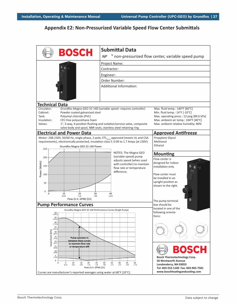
EthanolMethanolMagna GEO motor
Amps @230V*
Watts @230V*
to maintain flow rateor temperature diff.
Magna GEO (lowest duty cycle -- highest flow/head)
Magna GEO (highest duty cycle -- lowest flow/head)
set flow rate or temperature difference.
[0.32 0.63 0.95 1.26 1.58 1.89 2.21 2.52 2.84 3.15]
[134]
[15]
[30]
[45]
[60]
[75]
[90]
[105]
[119]
[149]
[164]
[179]
[194]
[209]
[224]
[239]
Magna GEO
Bosch Thermotechnology Corp.50 Wentworth Avenue Londonderry, NH 03053Tel: 603-552-1100 Fax: 603-965-7581www.boschhea�ngandcooling.com

26 | Universal Pump Controller (UPC-GEO) by Grundfos Installation, Operating & Maintenance Manual
Bosch Thermotechnology Corp.Data subject to change
Appendix E1: Pressurized Variable Speed Flow Center Submi als
13-1/4 5
A WEIGHTIHGFEDCB
Inches
CM
LBS KG3/8” DRIVE
SOCKET
212-1/24-3/49-7/168-1/210-3/16
33.6 5.031.712.024.021.625.9 12.7
E
A
D
F
B
H
G
C
I
13.630.0
Fluid connections are Flo-Link™ double O-ring
x Flo-Link™ is used on the ground loop connec-tions. A Bosch hose kit designed for Flo-Link™
pump connections.
speed pump with a blank plate kit.
[0.13 0.25 0.38 0.50 0.63 0.76 0.88 1.00 1.14 1.26 1.39 1.51 1.64 1.77 1.89 2.02 2.15 2.27]
[0.63 1.26 1.89 2.52]
Bosch Thermotechnology Corp.50 Wentworth Avenue Londonderry, NH 03053Tel: 603-552-1100 Fax: 603-965-7581www.boschhea�ngandcooling.com
Installation, Operating & Maintenance Manual Universal Pump Controller (UPC-GEO) by Grundfos | 27
Bosch Thermotechnology Corp. Data subject to change
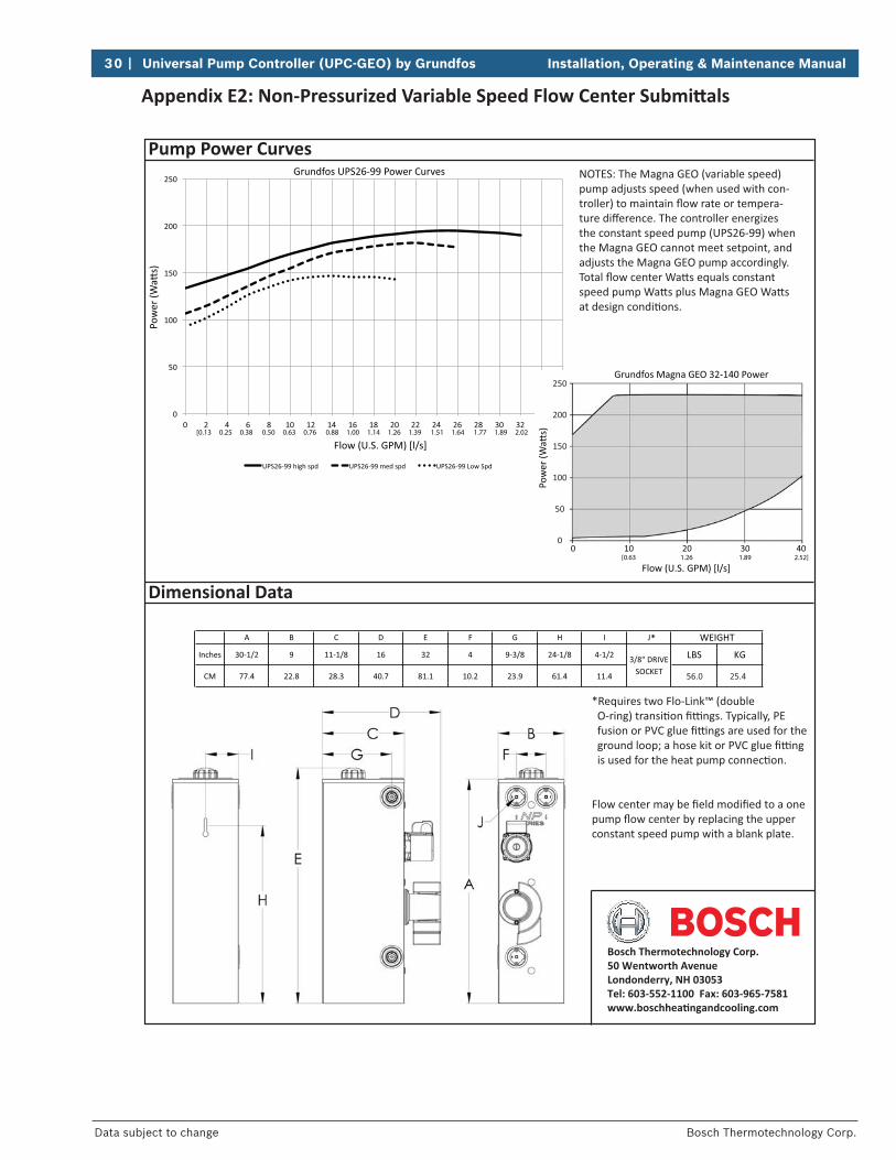
Appendix E2: Non-Pressurized Variable Speed Flow Center Submi als
.
[0.32 0.63 0.95 1.26 1.58 1.89 2.21 2.52 2.84 3.15]
to maintain flow rateor temperature diff.
[134.3]
[14.9]
[29.8]
[44.8]
[59.7]
[74.6]
[89.5]
[104.5]
[119.4]
[149.2]
[0.63 1.26 1.89 2.52]
NP V
Bosch Thermotechnology Corp.50 Wentworth Avenue Londonderry, NH 03053Tel: 603-552-1100 Fax: 603-965-7581www.boschhea�ngandcooling.com
28 | Universal Pump Controller (UPC-GEO) by Grundfos Installation, Operating & Maintenance Manual
Bosch Thermotechnology Corp.Data subject to change
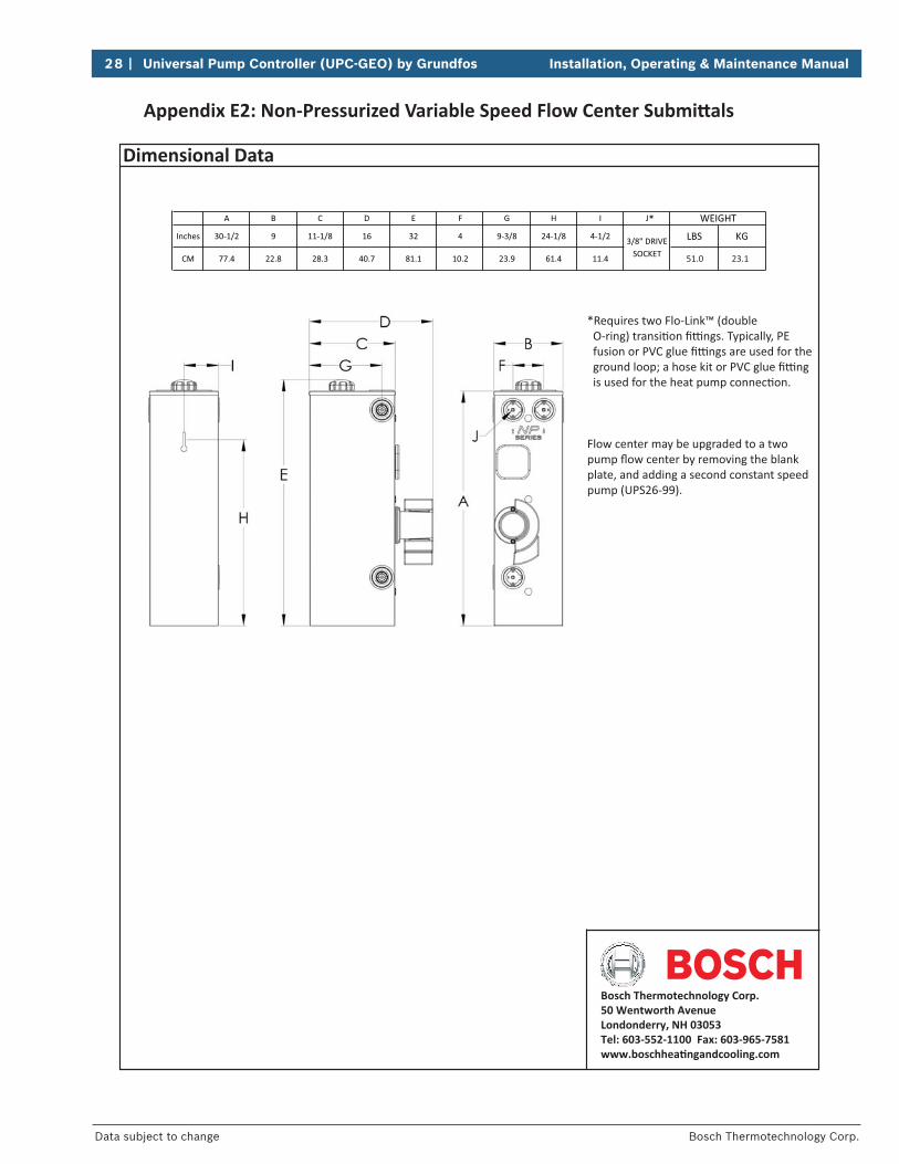
Appendix E2: Non-Pressurized Variable Speed Flow Center Submi als
*
Bosch Thermotechnology Corp.50 Wentworth Avenue Londonderry, NH 03053Tel: 603-552-1100 Fax: 603-965-7581www.boschhea�ngandcooling.com

Installation, Operating & Maintenance Manual Universal Pump Controller (UPC-GEO) by Grundfos | 29
Bosch Thermotechnology Corp. Data subject to change
Appendix E2: Non-Pressurized Variable Speed Flow Center Submi als
.
MethanolEthanol
shown to the right.
-
-
Magna GEO motor
to maintain flow rateor temperature diff.
Magna GEO (lowest duty cycle -- highest flow/head)
Magna GEO (highest duty cycle -- lowest flow/head)
set flow rate or temperature difference.
[0.32 0.63 0.95 1.26 1.58 1.89 2.21 2.52 2.84 3.15]
[134]
[15]
[30]
[45]
[60]
[75]
[90]
[105]
[119]
[149]
[164]
[179]
[194]
[209]
[224]
[239]
Magna GEO
NP V2
Bosch Thermotechnology Corp.50 Wentworth Avenue Londonderry, NH 03053Tel: 603-552-1100 Fax: 603-965-7581www.boschhea�ngandcooling.com
30 | Universal Pump Controller (UPC-GEO) by Grundfos Installation, Operating & Maintenance Manual
Bosch Thermotechnology Corp.Data subject to change
Appendix E2: Non-Pressurized Variable Speed Flow Center Submi als
[0.13 0.25 0.38 0.50 0.63 0.76 0.88 1.00 1.14 1.26 1.39 1.51 1.64 1.77 1.89 2.02 2.15 2.27]
[0.63 1.26 1.89 2.52]
Bosch Thermotechnology Corp.50 Wentworth Avenue Londonderry, NH 03053Tel: 603-552-1100 Fax: 603-965-7581www.boschhea�ngandcooling.com
Installation, Operating & Maintenance Manual Universal Pump Controller (UPC-GEO) by Grundfos | 31
Bosch Thermotechnology Corp. Data subject to change
Appendix F: An freeze Fluid Factors
The UPC-GEO controller calculates Heat of Extrac on (HE) and Heat of Rejec on (HR) based upon the Media Confi gura on menu (Figure 14). The Media Confi gura on page allows se ng the type and percentage of an- freeze used in the ground loop system. The type choices are ethanol, methanol, glycol, and none. The Media
inputs only aff ect the HE/HR calcula on. HE/HR is calculated as follows:
HE or HR = ∆T x Flow Rate (U.S. GPM) x Fluid Factorwhere: ∆T = temperature diff erence between EWT and LWT Fluid factor = adjustment for an freeze
It is possible that the calcula on shown on the controller screen is diff erent than a hand calcula on. The reason that the calcula on could be diff erent is the use of fl uid factor. The UPC-GEO calcula on is based upon the weight of the fl uid, specifi c heat, percentage of an freeze, and fl uid temperature. Some calcula ons in the geothermal heat pump industry use a fl uid factor of 500 for water, and a fl uid factor for all an freezes of 485. While this will make the calcula on easier, and allow the technician to be “in the ballpark”, it may not match the controller display, which uses calcula ons specifi c to the current condi ons.

32 | Universal Pump Controller (UPC-GEO) by Grundfos Installation, Operating & Maintenance Manual
Bosch Thermotechnology Corp.Data subject to change
NOTES

Installation, Operating & Maintenance Manual Universal Pump Controller (UPC-GEO) by Grundfos | 33
Bosch Thermotechnology Corp. Data subject to change
NOTES

Bosch Thermotechnology Corp.50 Wentworth AvenueLondonderry, NH 03053
Tel: 603-552-1100Fax: 603-965-7581www.boschheatingandcooling.com
For Technical Support:Tel: 866-642-3198
BTC 760701305 A | 4025 | 05.2015


