Universal I Series - Homepage - Hayward Gordon · 2017-05-24 · Universal I Series ROTARY POSITIVE...
120
INSTRUCTION MANUAL Universal I Series ROTARY POSITIVE DISPLACEMENT PUMP FORM NO.: 95-03002 REVISION: 01/2017 READ AND UNDERSTAND THIS MANUAL PRIOR TO OPERATING OR SERVICING THIS PRODUCT.
Transcript of Universal I Series - Homepage - Hayward Gordon · 2017-05-24 · Universal I Series ROTARY POSITIVE...
INSTRUCTION MANUAL
Universal I SeriesROTARY POSITIVE DISPLACEMENT PUMP
FORM NO.: 95-03002 REVISION: 01/2017 READ AND UNDERSTAND THIS MANUAL PRIOR TO OPERATING OR SERVICING THIS PRODUCT.

Information contained in this manual is subject to change without notice and does not represent a commitment on the part of SPX FLOW, Inc. No part of this manual may be reproduced or transmitted in any form or by any means, electronic or mechanical, including photocopying and recording, for any purpose, without the express written per-mission of SPX FLOW, Inc.
Copyright © 2017 SPX FLOW, Inc.All Rights Reserved.
Revision Date: 01/2017
Publication: 95-03002
SPX FLOW, Inc.611 Sugar Creek Road
Delavan, WI 53115 USA
Tel: (800) 252-5200 or (262) 728-1900Fax: (800) 252-5012 or (262) 728-4904
E-mail: [email protected] site: www.spxflow.com

Waukesha Cherry-Burrell Brand Universal I Pump Table of Contents
Warranty ....................................................................................................................5Shipping Damage or Loss ....................................................................................................... 5Warranty Claim ........................................................................................................................ 5
Safety ........................................................................................................................6Replacement Labels ................................................................................................7Care of Stainless Steel ............................................................................................8
Stainless Steel Corrosion ........................................................................................................ 8Alloy 88 .................................................................................................................................... 8Elastomer Seal Replacement Following Passivation ............................................................... 8
Introduction ..............................................................................................................9Pump Receiving ...................................................................................................................... 9Pump Characteristics .............................................................................................................. 9Equipment Serial Number ....................................................................................................... 9Pump Shaft Location ............................................................................................................... 9Operating Parameters ........................................................................................................... 10Factory Remanufacturing Program ........................................................................................ 11
Installation ..............................................................................................................12Install Pump and Drive Unit ................................................................................................... 12Install Connections and Piping .............................................................................................. 13Install Check Valves .............................................................................................................. 14Install Isolation Valves ........................................................................................................... 14Install Relief Valves ............................................................................................................... 14Inlet Side Strainers and Traps ............................................................................................... 15Install Pressure Gauges ........................................................................................................ 15Check Coupling Alignment .................................................................................................... 15Check Angular Alignment ...................................................................................................... 16Check Parallel Alignment ...................................................................................................... 16Check Belt and Chain Drive Alignment .................................................................................. 16Check Pump Rotation ............................................................................................................ 17
Operation ................................................................................................................18Pre-Startup Checklist ............................................................................................................. 18Startup Procedure ................................................................................................................. 18Shutdown Procedure ............................................................................................................. 18Emergency Shutdown Procedure .......................................................................................... 18
Maintenance ...........................................................................................................19Important Safety Information ................................................................................................. 19Lubrication ............................................................................................................................. 19Maintenance Inspections ....................................................................................................... 20Maintenance Inspection Chart ............................................................................................... 22Annual Maintenance .............................................................................................................. 23Cleaning ................................................................................................................................ 23Fluid Head Disassembly (All Models) .................................................................................... 24Model 320 and 324 Body Disassembly ................................................................................. 25Model 323 Aseptic Body Disassembly ................................................................................... 25Seal Maintenance .................................................................................................................. 26Gear Case Disassembly ........................................................................................................ 32Shaft Assembly ...................................................................................................................... 34Gear Case Assembly ............................................................................................................. 37Fluid Head Assembly ............................................................................................................. 43Jacketed Cover ...................................................................................................................... 46Reference Tables .................................................................................................................. 47
01/2017 95-03002 Page 3
Table of Contents Waukesha Cherry-Burrell Brand Universal I Pump
Long Term Storage ................................................................................................ 49Before Storage .......................................................................................................................49Storage ...................................................................................................................................49After Storage ..........................................................................................................................49
Parts List ................................................................................................................ 50006, 014, 015, 018, 024-UI Pump Parts .................................................................................50006, 014, 015, 018, 024-UI Common Parts ...........................................................................52030, 033A, 034, 040-UI Pump Parts ......................................................................................56030, 033A, 034, 040-UI Common Parts .................................................................................58060, 064, 130, 134, 133A-UI Pump Parts ..............................................................................64060, 064, 130, 134, 133A-UI Common Parts .........................................................................66220, 223A, 224-UI Pump Parts ..............................................................................................72220, 223A, 224-UI Common Parts .........................................................................................74320, 323A, 324-UI Pump Parts ..............................................................................................80320, 323A, 324-UI Common Parts .........................................................................................82PD Pump Seals Model 006, 014, 015, 018, 024, 030, 034, 040-UI .......................................86PD Pump Seals Model 060, 064, 130, 133A, 134, 220, 223A, 224-UI ..................................88PD Pump Seals Model 320, 323A, 324-UI (April 2015 and newer) .......................................90PD Pump Seals Model 320, 323A, 324-UI (Pre-April 2015) ..................................................92PD Pump Seal Kits - 006, 015, 018-UI ...................................................................................94PD Pump Seal Kits - 014, 024-UI ...........................................................................................95PD Pump Seal Kits - 030, 034, 040-UI ...................................................................................96PD Pump Seal Kits - 060, 130-UI ...........................................................................................97PD Pump Seal Kits - 064, 134-UI ...........................................................................................98PD Pump Seal Kits - 220-UI ...................................................................................................99Universal I PD Pump Vented Covers ...................................................................................100Tru-Fit™ Universal I PD Pumps Parts List ...........................................................................102Shaft Assemblies with Pressed-on Bearings .......................................................................103Grease Seal, Bearing Retainer, O-Ring Seal Carrier Part No. Reference ...........................104Special Tools ........................................................................................................................105
Pump Dimensions ............................................................................................... 106Universal I PD Pump Dimensions ........................................................................................106Universal I PD Pump Dimensions - Rectangular Flange with Pedestal ...............................108Tru-Fit™ Universal I PD Pump Dimensions .........................................................................110
Troubleshooting .................................................................................................. 112Universal I Maintenance Summary Reference Sheet ....................................... 116Universal I Maintenance Summary Reference Sheet -
Copy for optional removal .................................................. 117
Page 4 95-03002 01/2017

Waukesha Cherry-Burrell Brand Universal I Pump Warranty
01/2017 95-03002 Page 5
Warranty
LIMITED WARRANTY: Unless otherwise negotiated at the time of sale, SPX FLOW US, LLC (SPX FLOW) goods, auxiliaries and parts thereof are warranted to the original purchaser against defective workmanship and material for a period of twelve (12) months from date of installation or eighteen (18) months from date of shipment from factory, whichever expires first. If the goods or services do not conform to the warranty stated above, then as Buyer's sole remedy, SPX FLOW shall, at SPX FLOW's option, either repair or replace the defective goods or re-perform defective services. Third party goods furnished by SPX FLOW will be repaired or replaced as Buyer's sole remedy, but only to the extent provided in and honored by the original manufacturer's warranty. Unless otherwise agreed to in writing, SPX FLOW shall not be liable for breach of warranty or otherwise in any manner whatsoever for: (i) normal wear and tear; (ii) corrosion, abrasion or erosion; (iii) any good or services which, following delivery or performance by SPX FLOW, has been subjected to accident, abuse, misapplication, improper repair, alteration, improper installation or maintenance, neglect, or excessive operating con-ditions; (iv) defects resulting from Buyer's specifications or designs or those of Buyer's contractors or subcontractors other than SPX FLOW; or (v) defects resulting from the manufacture, distribution, promotion or sale of Buyer's products.
THE WARRANTIES CONTAINED HEREIN ARE THE SOLE AND EXCLUSIVE WARRANTIES AVAILABLE TO BUYER AND SPX FLOW HEREBY DISCLAIMS ANY OTHER WARRANTIES, EXPRESS OR IMPLIED, INCLUDING WITHOUT LIMITATION THE IMPLIED WARRANTIES OF MERCHANTABILITY AND FITNESS FOR A PARTICULAR PURPOSE. THE FOREGOING REPAIR, REPLACEMENT AND RE-PERFORMANCE OBLIGA-TIONS STATE SPX FLOW'S ENTIRE AND EXCLUSIVE LIABIL-ITY AND BUYER'S EXCLUSIVE REMEDY FOR ANY CLAIM IN CONNECTION WITH THE SALE AND FURNISHING OF SER-VICES, GOODS OR PARTS, THEIR DESIGN, SUITABILITY FOR USE, INSTALLATION OR OPERATIONS.
Shipping Damage or Loss If equipment is damaged or lost in transit, file a claim at once with the delivering carrier. The carrier has a signed Bill of Lading acknowledging that the shipment has been received from SPX FLOW in good condition. SPX FLOW is not responsible for the collection of claims or replacement of materials due to transit shortage or damages.
Warranty Claim Warranty claims must have a Returned Material Authorization (RMA) from the Seller or returns will not be accepted. Contact 800-252-5200 or 262-728-1900.
Claims for shortages or other errors must be made in writing to Seller within ten (10) days after delivery. This does not include transit shortage or damages. Failure to give such notice shall constitute acceptance and waiver of all such claims by Buyer.
Safety Waukesha Cherry-Burrell Brand Universal I Pump
Page 6 95-03002 01/2017
SafetyREAD AND UNDERSTAND THIS MANUAL PRIOR TO INSTALLING, OPERATING, OR SERVICING THIS EQUIPMENT
SPX FLOW recommends users of our equipment and designs follow the latest Industrial Safety Standards. At a minimum, these should include the industrial safety requirements established by:
1. Occupational Safety and Health Administration (OSHA)
2. National Fire Protection Association (NFPA)
3. National Electrical Code (NEC)
4. American National Standards Institute (ANSI)
WARNING: Severe injury or death can result from electrical shock, burn, or unintended actuation of equipment. Recommended practice is to disconnect and lockout industrial equipment from power sources, and release stored energy, if present. Refer to the National Fire Protection Association Standard No. NFPA70E, Part II and (as applicable) OSHA rules for Control of Hazardous Energy Sources (Lockout-Tagout) and OSHA Electrical Safety Related Work Practices, including procedural requirements for:
• Lockout-tagout
• Personnel qualifications and training requirements
• When it is not feasible to de-energize and lockout-tagout electrical circuits and equipment before working on or near exposed circuit parts
Locking and Interlocking Devices: These devices should be checked for proper working condition and capability of performing their intended functions. Make replacements only with the original equipment manufacturer’s OEM renewal parts or kits. Adjust or repair in accordance with the manufacturer’s instructions.
Periodic Inspection: Equipment should be inspected periodically. Inspection intervals should be based on environmental and operating conditions and adjusted as indicated by experience. At a minimum, an initial inspection within 3 to 4 months after installation is recommended. Inspection of the electrical control systems should meet the recommendations as specified in the National Electrical Manufacturers Association (NEMA) Standard No. ICS 1.3, Preventative Maintenance of Industrial Control and Systems Equipment, for the general guidelines for setting-up a periodic maintenance program.
Replacement Equipment: Use only replacement parts and devices recommended by the manufacturer to maintain the integrity of the equipment. Make sure the parts are properly matched to the equipment series, model, serial number, and revision level of the equipment.
Warnings and cautions are provided in this manual to help avoid serious injury and/or possible damage to equipment:
DANGER: marked with a stop sign. Immediate hazards which WILL result in severe personal injury or death.
WARNING: marked with a warning triangle. Hazards or unsafe practices which COULD result in severe personal injury or death.
CAUTION: marked with a warning triangle. Hazards or unsafe practices which COULD result in minor personal injury or product or property damage.

Waukesha Cherry-Burrell Brand Universal I Pump Replacement Labels
01/2017 95-03002 Page 7
Replacement Labels
WARNING: The following labels are installed on your equipment. If these labels are removed or become unreadable, contact your local distributor. Refer to the parts lists starting on page 50 for replacement part numbers.
Application Instructions Apply to a clean, dry surface. Remove the backing from the label, place it in proper position, protect it with a cover sheet and burnish it. (A soft rubber roller also may be used to press the label into place.) Apply all labels to be readable from the front of the pump.
PUMP030,032
PUMP030,032
PUMP030,032
PUMP030,032
WARNINGKEEP FINGERSOUT OF PORTS
WA
RN
ING
KEEP FINGERSOUT OF PORTS
WA
RN
ING
KEEP FINGERSOUT OF PORTS
Read and understand operation manual before using this machine.Failure to follow operating instructions could result in injury or damage to equipment.
WAR
NIN
G
Read and understand operation manual before using this machine.Failure to follow operating instructions could result in injury or damage to equipment.
WAR
NIN
G
Read and understand operation manual before using this machine.Failure to follow operating instructions could result in injury or damage to equipment.
WARNING
02-XX
02-XX
label locations-U1

Care of Stainless Steel Waukesha Cherry-Burrell Brand Universal I Pump
Page 8 95-03002 01/2017
Care of Stainless Steel
NOTE: SPX FLOW recommends the use of an FDA-approved anti-seize compound on all threaded connections.
Stainless Steel Corrosion
Corrosion resistance is greatest when a layer of oxide film is formed on the surface of stainless steel. If film is disturbed or destroyed, stainless steel becomes much less resistant to corrosion and may rust, pit or crack.
Corrosion pitting, rusting and stress cracks may occur due to chemical attack. Use only cleaning chemicals specified by a reputable chemical manufacturer for use with 300 series stainless steel. Do not use excessive concentrations, temperatures or exposure times. Avoid contact with highly corrosive acids such as hydrofluoric, hydrochloric or sulfuric. Also avoid prolonged contact with chloride-containing chemicals, especially in presence of acid. If chlorine-based sanitizers are used, such as sodium hypochlorite (bleach), do not exceed concentrations of 150 ppm available chlorine, do not exceed contact time of 20 minutes, and do not exceed temperatures of 104°F (40°C).
Corrosion discoloration, deposits or pitting may occur under product deposits or under gaskets. Keep surfaces clean, including those under gaskets or in grooves or tight corners. Clean immediately after use. Do not allow equipment to set idle, exposed to air with accumulated foreign material on the surface. Corrosion pitting may occur when stray electrical currents come in contact with moist stainless steel. Ensure all electrical devices connected to the equipment are correctly grounded.
Alloy 88
Waukesha Alloy 88 is the standard rotor material for Universal I, Universal II, Universal Lobe, Universal 420/520 and 5000 Series Rotary PD pumps. This alloy was developed specifically for corrosion resistance and close operating clearance requirements of high performance rotary positive displacement pumps. Alloy 88 is a nickel based, corrosion-resistant, non-galling or seizing material. The ASTM designation is A494 Grade CY5SnBiM (UNS N26055), and the material is listed in the 3-A Sanitary Standards as acceptable for product contact surfaces.
The above properties make Alloy 88 the ideal material for Waukesha Cherry-Burrell brand stainless steel PD pumps. The non-galling rotors permit close operating clearances in the liquid end. This provides low slip and minimum shear damage. The rotors will not gall or seize if they come in contact with the body or cover during operation.
The corrosion resistance of Alloy 88 is approximately equal to AISI 300 Series Stainless Steel. However, Alloy 88 has limited resistance to certain aggressive chemicals that may be commonly used in contact with AISI 300 Series Stainless Steel.
Do not use Alloy 88 in contact with nitric acid. Nitric acid is commonly used to passivate new installations of stainless steel equipment. Do not allow nitric acid based passivation chemicals to contact Alloy 88 rotors. Remove the rotors during passivation and use a separate pump to circulate the passivation chemicals. Also, if nitric acid-based CIP cleaning chemicals are used, remove the rotors prior to CIP cleaning and clean them separately by hand in a mild detergent. If you have questions regarding other aggressive chemicals, please contact SPX FLOW Application Engineering for assistance.
Elastomer Seal Replacement Following Passivation
Passivation chemicals can damage product contact areas of this equipment. Elastomers (rubber components) are most likely to be affected. Always inspect all elastomer seals after passivation is completed. Replace any seals showing signs of chemical attack. Indications may include swelling, cracks, loss of elasticity or any other noticeable changes when compared with new components.

Waukesha Cherry-Burrell Brand Universal I Pump Introduction
Introduction
Pump Receiving
DANGER: The pump contains internal moving parts. DO NOT put hands or fingers into the pump body ports or drive area at any time during operation. To avoid serious injury, DO NOT install, clean, service, or repair the pump unless all power is off and locked out.
All ports are covered at the factory to keep out foreign objects during transit. If covers are missing or damaged, remove the pump cover for a thoroughly inspect the fluid head. Be sure that the pumping head is clean and free of foreign material before rotating the shaft.
Each Waukesha Cherry-Burrell brand pump is shipped completely assembled, lubricated and ready for use. Review “Operation” on page 18 before operating the pump.
Pump Characteristics Waukesha Cherry-Burrell brand Universal I pumps are positive-displacement, low-slip, stainless steel pumps designed with larger diameter shafts for greater strength and stiffness, mounted on a heavy-duty cast iron bearing frame (stainless steel option available) with double-tapered roller bearings.
• Up to 200 psi (13.8 bar) pressure capability.
• No bearings in the product zone.
• Heavy-duty bearing frame with large diameter shafts.
• Greased lubed bearings for positive lubrication to all bearings over entire speed, temperature and pressure range.
• Exclusive, non-galling Waukesha “88” alloy rotors are standard; permits running at tighter clearances and pumping a wide range of viscosities.
Equipment Serial Number All Waukesha Cherry-Burrell brand pumps are identified by a serial number on the gear case nameplate, which is stamped on the pump body and cover.
CAUTION: The gear case, body, and cover must be kept together as a unit due to backface, rotor, and cover clearances. Failure to do so will damage the pump.
Pump Shaft Location There are two pump drive shaft locations:
PD100-037b
PD100-036b
PD100-038b
PD100-237b
Figure 1 - Upper and Lower Shaft Mount Figure 2 - Sidemount Left Hand and Right Hand (as viewed from pump cover)
01/2017 95-03002 Page 9

Introduction Waukesha Cherry-Burrell Brand Universal I Pump
Operating Parameters
UIModel
Displacement per revolution
MaximumNominalCapacity
Inlet/Outlet
OptionalInlet/Outlet
MaximumPressure
Range
MaximumRPM
TempRange*
006 .0082 gal (.031 liter) 6 gpm (1.3 m3/hr.) 1" 1-1/2" 200 psi (13.8 bar) 800
Std: 40°F (-40°C) to
180°F (82°C);
FF: 180°F (82°C) to 200°F
(93°C);
Hot/XHot: -40°F (-40°C) to
300°F (149°C)
015 .0142 gal (.054 liter) 9 gpm (2.0 m3/hr.) 1-1/2" - 200 psi (13.8 bar) 700
018 .029 gal (.110 liter) 17 gpm (3.8 m3/hr.) 1-1/2" 2" 200 psi (13.8 bar) 600
030 .060 gal (.227 liter) 36 gpm (8.2 m3/hr.) 1-1/2" 2" 200 psi (13.8 bar) 600
040 .076 gal (.288 liter) 45 gpm(10.2 m3/hr.) 2" 2-1/2" 150 psi (10.3 bar) 600
060 .153 gal (.579 liter) 90 gpm (20.4 m3/hr.) 2-1/2" 3" 200 psi (13.8 bar) 600
130 .254 gal (.961 liter) 150 gpm (34.1 m3/hr.) 3" - 200 psi (13.8 bar) 600
220 .522 gal (1.976 liter) 310 gpm (70.4 m3/hr.) 4" - 200 psi (13.8 bar) 600
320 .754 gal (2.854 liter) 450 gpm (102 m3/hr.) 6" - 200 psi (13.8 bar) 600
Rectangular Flange Models
UIModel
Displacement per revolution
MaximumNominal Capacity
InletW x LInches
OutletMaximumPressure Range
Max.RPM
Temp Range *
014 .0142 gal (.054 liter) 5.68 gpm (1.3 m3/hr.) 1.44 x 4.94 1-1/2" 200 psi (13.8 bar) 400 Std: 40°F (-40°C) to
180°F (82°C);
FF: 180°F (82°C) to 200°F
(93°C);
Hot/XHot: -40°F(-40°C) to 300°F
(149°C)
024 .026 gal (.110 liter) 11 gpm (2.5m3/hr.) 1.31 x 4.93 1-1/2" (2") 200 psi (13.8 bar) 400
034 .060 gal (.227 liter) 24 gpm (5.5 m3/hr.) 1.75 x 6.75 2" 200 psi (13.8 bar) 400
064 .153 gal (.579 liter) 60 gpm (13.6 m3/hr.) 2.24 x 8.82 2-1/2" (3") 200 psi (13.8 bar) 400
134 .254 gal (.961 liter) 100 gpm (22.7 m3/hr.) 2.97 x 9.25 3" 150 psi (10.3 bar) 400
224 .522 gal (1.976 liter) 200 gpm (45.4 m3/hr.) 3.87 x 11 4" 200 psi (13.8 bar) 400
324 .754 gal (2.854 liter) 300 gpm (68.1 m3/hr.) 5 x 17.38 6" 200 psi (13.8 bar) 400
Aseptic Models
UIModel
Displacement per revolution
MaximumNominal Capacity
Inlet/Outlet
MaximumPressure Range
MaximumRPM
Temp Range *
033A .051 gal (.193 liter) 30 gpm (6.8 m3/hr.) 1-1/2" 225psi (15.5 bar) 600 Std: 40°F (-40°C) to 180°F (82°C);
FF: 180°F (82°C) to 200°F (93°C);
Hot/XHot: -40°F (-40°C)to 300°F (149°C)
133A .205 gal (.776 liter) 120 gpm (27.3 m3/hr.) 3" 225psi (15.5 bar) 600
223A .440 gal (1.666 liter) 260 gpm (59.1m3/hr.) 4" 225psi (15.5 bar) 600
323A .616 gal (2.332 liter) 360 gpm (81.8 m3/hr.) 6" 225psi (15.5 bar) 600
Std = Standard Clearance Rotors; FF = Front Face Clearance Rotors; Hot = Hot Clearance Rotors; XHot = Extra Hot Clearance Rotors
Other inlet/outlet sizes are available. Contact SPX FLOW Application Engineering.
* Contact SPX FLOW Application Engineering for higher pressures or higher temperature applications. Pump max temperature is 300°F (149°C).
Page 10 95-03002 01/2017

Waukesha Cherry-Burrell Brand Universal I Pump Introduction
"Standard" and "Wine" clearance rotors may be used with liquid temperatures up to 180°F (82°C). However, between 160°-200°F (71°-93°C), consider other application factors such as:
• speed of operation
• differential pressure
• lubricating properties of liquid being pumped
• product viscosity
If these factors trend toward a difficult application (high speed, high pressure, non-lubricating) then "Front Face" or "Hot" clearance rotors are recommended. Wine clearance rotors (same operating parameters as listed for standard rotors) provide additional clearance between the rotor hub and the cover bore area only. They give extra protection against contact in this area.
"FF" (Front Face) clearance rotors provide additional clearance in the front face area only. They are recommended for use with liquid temperature between 180°F (82°C) to 200°F (93°C). They give better pumping efficiency (less slip) than "Hot" clearance rotors when used with low viscosity liquids. However, do not use "FF" rotors if they will be subjected to temperature shock (extreme, rapid temperature change.)
"Hot" clearance rotors are recommended for use with liquid temperatures between 180°F (82°C) to 300°F (149°C). They provide additional clearance in the front face area plus rotor to body areas. Because of this additional clearance there is more slip (inefficiency) with low viscosity liquids, which the pump must overcome with higher operating speed (rpm.) VHP (viscous horsepower) is slightly lower when using hot clearance rotors. Hot clearance rotors are also used when the product viscosity is above 200 CPS.
"316SS" clearance rotors are used with rotors made from 316 stainless steel material (in place of standard non-galling alloy 88) and recommended for use at temperatures up to 200°F (93°C). These rotors provide additional clearance all around (more than Hot clearance alloy 88 rotors) to insure no running contact between the 316 SS rotors and other 316 SS pump components. Because of this additional clearance there is more slip (inefficiency) with low viscosity liquids, which the pump must overcome with higher operating speed (rpm). VHP (viscous horsepower) is slightly lower when using "316SS" clearance rotors.
Some models in some series have a "316SS Hot" clearance rotor option for temperature above 200°F (93°C).
NOTE: Consult SPX FLOW Technical Services for applications near 300°F or above 200°F with 316 SS rotors.
"Extra Hot" clearance rotors are recommended for use with products such as chocolate, which tend to "plate out" and build up on rotor surfaces. These rotors require special selection procedures. Contact SPX FLOW Technical Services for assistance.
Single wing rotors are available for certain pump models. They are recommended for applications pumping particulates with minimal damage. These rotors perform the same as standard twin wing rotors. DO NOT USE ABOVE 300 RPM. Single wing rotors are not available for use with RF (rectangular flange) models.
For clearance data, see Table 2, “Rotor Clearances,” on page 41.
Factory Remanufacturing Program
Waukesha Cherry-Burrell brand Universal I pumps are designed so that they may be factory remanufactured twice and backed with a new pump warranty each time.
Factory remanufacturing involves replacement of all shafts, bearings, oil seals, gears, etc. The pump body and cover are re-machined and new oversized rotors are installed. The pumps are stamped R-1 or R-2, after the serial number, designating that they have been reconditioned once or twice.
Contact your SPX FLOW Customer Service Representative at 1-800-252-5200 and furnish the serial number of any pump being considered for remanufacturing.
01/2017 95-03002 Page 11

Installation Waukesha Cherry-Burrell Brand Universal I Pump
Installation
Install the pump and piping system in accordance with local codes and restrictions. Practices described in this manual are recommended for optimum performance.
All system equipment, such as motors, sheaves, drive couplings, speed reducers, etc., must be properly sized to ensure satisfactory operation of your Waukesha Cherry-Burrell brand pump within its limits.
CAUTION: These pumps are positive displacement, low slip design and will be severely damaged if operated with closed valves in discharge or inlet lines. The pump warranty is not valid for damages caused by a hydraulic overload from operation or start-up with a closed valve in the system.
Install Pump and Drive Unit WARNING: Full guards must be installed to isolate operators and maintenance personnel from rotating components. Guards are provided with Waukesha Cherry-Burrell brand pumps as part of a complete pump and drive package.
In a typical installation configuration, the pump and drive unit are mounted on a common base plate. The unit can be installed in any of the arrangements shown in Figure 3 through Figure 6 (the shaded area indicates the guard location).
NOTE: When installing unit as shown in Figure 6, level the unit before installing the bolts.
Figure 3 - Portable Base
Figure 4 - Adjustable Leg Base
Figure 5 - Leveling and/or Vibration Isolation Pads
Figure 6 - Permanent Installation on Foundation
Page 12 95-03002 01/2017

Waukesha Cherry-Burrell Brand Universal I Pump Installation
Install Connections and Piping
Piping SupportTo minimize forces exerted on the pump, support all piping to the pump independently with hangers or pedestals. Such forces can cause misalignment of the pump parts and lead to excessive wear of rotors, bearings, and shafts.
Figure 7 shows typical supporting methods used to independently support each pipe, reducing the weight effect of piping and fluid on the pump.
Expansion JointsThermal expansion of piping can cause tremendous forces. Use thermal expansion joints to minimize these forces on the pump.
Flexible joints can be used to limit transmission of mechanical vibration. Ensure that the free ends of any flexible connections in the system are anchored.
Inlet PipingInstall the pump below the supply liquid level to reduce the air in the system by flooded suction (Figure 9).
If the pump is installed above the supply liquid level, the piping on the inlet side must slope up toward the pump, preventing air pockets in the pipes (Figure 10).
Figure 7 - Piping Support
Figure 8 - Flexible Connections and Supports
Figure 9 - Pump Below Supply
Figure 10 - Correct Piping to Prevent Inlet Air Pockets
01/2017 95-03002 Page 13

Installation Waukesha Cherry-Burrell Brand Universal I Pump
Install Check Valves Inlet Side on Lift ApplicationsUse check valves to keep the inlet line full, particularly with low-viscosity fluids (Figure 11).
Discharge SideFor systems with liquid under a vacuum, install a check valve onthe discharge side of the pump. The check valve prevents backflow (air or fluid) to aid in the initial start-up by minimizing the required differential pressure supplied by the pump to start the flow (Figure 12).
Install Isolation ValvesIsolation valves permit pump maintenance and safe pump removal without draining the system (Figure 13, item A).
Install Relief ValvesInstall relief valves to protect the pump and piping system against excessive pressure. We recommend installing an external relief valve designed to bypass fluid from the pump outlet to the inlet side of the system (Figure 14, item A).
NOTE: Integral relief valves are available, but are not recommended on applications with viscosities over 5000 cP or where the discharge must be closed for more than a few minutes. Prolonged operation of the pump with closed discharge will cause heating of fluid circulating through the relief valve. If this is the case, install an external relief valve to discharge externally through the piping connected to the fluid source, or into inlet piping near the source.
A. Inlet Check ValveB. Foot Check Valve
Figure 11 - Inlet Check Valve
A. Closed Tank - produces vacuum on liquid (Low Absolute Pressure)
B. Check Valve (outlet)
Figure 12 - Discharge Check Valve
Figure 13 - Isolation Valves
Figure 14 - Relief Valves
Page 14 95-03002 01/2017

Waukesha Cherry-Burrell Brand Universal I Pump Installation
Inlet Side Strainers and Traps
Inlet side strainers and traps (Figure 15, items A and B, respectively) can be used to prevent foreign matter from damaging the pump. Select carefully to prevent cavitation caused by the restriction of the inlet. If inlet strainers are used, they must be serviced regularly to prevent clogging and flow stoppage.
Install Pressure GaugesPressure and vacuum gauges provide valuable information about pump operation (Figure 16). Wherever possible, install the gauges to help provide information on the following:
• Normal or abnormal pressures
• Indication of flow
• Changes in pump condition
• Changes in system conditions
• Changes in fluid viscosity
Check Coupling AlignmentPumps and drives ordered from the factory and mounted on a common base plate are aligned before shipment. Alignment must be re-checked after the complete unit has been installed and piping completed. Periodic re-checking is advisable during the pump service life.
SPX FLOW recommends using a flexible coupling to connect the drive to the pump. Several different types are available, including couplings with slip or overload provisions. SPX FLOW provides Lovejoy (Figure 17) or T.B. Woods® (Figure 18) couplings unless otherwise specified when ordering. Flexible couplings can be used to compensate for end play and small differences in alignment.
Align the pump and drive shaft as closely as possible:
• Pump and Drive are factory aligned.
• Re-check alignment after installation and before start-up.
• Re-check alignment periodically, to maximize service life.
A. Strainer B. Magnetic Trap
Figure 15 - Inline Strainers and Traps
Figure 16 - Pressure and Vacuum Gauges
Figure 17 - Lovejoy Coupling
Figure 18 - T.B. Woods® Coupling
01/2017 95-03002 Page 15

Installation Waukesha Cherry-Burrell Brand Universal I Pump
Check Angular Alignment1. Using feeler gauges or taper gauges (Figure 19, items A and
B), check the alignment at four points every 90 degrees around the coupling; adjust to equal dimension at all points.
2. Set the space between the coupling halves to the manufacturer’s recommended distance.
3. Install shims to bring the system into alignment.
Check Parallel Alignment1. Check both the horizontal and vertical alignment of the pump
and drive using a straight edge.
2. Using a feeler gauge at location “A” in Figure 20, determine the direction and amount of movement needed (Figure 20, item B).
3. If necessary, shim at location “C” and/or move drive as needed.
Check Belt and Chain Drive Alignment
Use a straight edge to visually check the belt or chain alignment. Keep the shaft distance to a minimum (Figure 21, item A).
After the piping is complete and before the belts are installed, manually turn the pump shaft to ensure it turns freely.
Figure 19 - Check Angular Alignment
Figure 20 - Check Parallel Alignment
Figure 21 - Aligning Belt and Chain Drives
Page 16 95-03002 01/2017

Waukesha Cherry-Burrell Brand Universal I Pump Installation
Check Pump Rotation Check the direction of the drive rotation to determine the rotation direction of pump (Figure 22). After the correct drive rotation is verified, connect the coupling and assemble the pump and coupling guards.
NOTE: The pump covers in the following figures have been removed to view the rotor rotation. Never operate the pump with the covers removed.
Figure 22 - Direction of Drive Rotation
Top ShaftDrive
Lower ShaftDrive
Lower Shaft Drive
Top Shaft Drive
01/2017 95-03002 Page 17

Operation Waukesha Cherry-Burrell Brand Universal I Pump
Page 18 95-03002 01/2017
Operation DANGER: The pump contains internal moving parts. DO NOT put hands or fingers into the pump body ports or drive area at any time during operation. To avoid serious injury, DO NOT install, clean, service, or repair the pump unless all power is off and locked out.
CAUTION: These pumps are positive displacement, low slip design and will be severely damaged if operated with closed valves in the discharge or inlet lines. The pump warranty is not valid for damages caused by a hydraulic overload from operation or start-up with a closed valve in the system.
Pre-Startup Checklist 1. Ensure that the pump is correctly installed as described in “Installation” on page 12. Review “Install Relief Valves” on page 14 and install relief valves as needed.
2. Check the coupling alignment. See “Check Coupling Align-ment” on page 15.
3. Ensure that the pump and piping are clean and free of foreign material such as welding slag, gaskets, etc.
CAUTION: Do not use this pump to flush a newly- installed system. Severe damage may occur to the pump and system if the pump is used to flush the system. Remove the rotors during system flushing.
4. Ensure that all piping connections are tight and leak-free. Where possible, check the system with non-hazardous fluid.
5. Ensure that the pump and drive are lubricated. See “Lubrica-tion” on page 19.
6. Ensure that all guards are in place and secure.
WARNING: Full guards must be installed to isolate the operators and maintenance personnel from the rotating components. Guards are provided with Waukesha Cherry-Burrell brand pumps as part of a complete pump and drive package.
7. Double mechanical seals require adequate supply and flow of clean flushing fluids.
8. Ensure that all valves are open on the discharge side and a free flow path is open to the destination.
9. Ensure that all valves are open on the inlet side and fluid can fill the pump. A flooded suction installation is recommended.
WARNING: Do not start a pump with seal flush unless the seal flush is installed and on.
10. Check the direction of pump and drive rotation to ensure that the pump will rotate in the proper direction. See “Check Pump Rotation” on page 17.
Startup Procedure 1. Start the pump drive. Where possible, start at a slow speed or jog.
2. Ensure that the liquid is reaching the pump within 60 sec-onds. If pumping does not begin and stabilize, check “Trou-bleshooting” on page 112.
Shutdown Procedure 1. Shut off the power to the pump drive.
2. Shut off the supply and discharge lines.
Emergency Shutdown Procedure
Emergency Shutdown Procedures should be documented by plant personnel after assessing system-wide requirements.

Waukesha Cherry-Burrell Brand Universal I Pump Maintenance
Maintenance
Important Safety Information
DANGER: The pump contains internal moving parts. DO NOT put hands or fingers into the pump body ports or drive area at any time during operation. To avoid serious injury, DO NOT install, clean, service, or repair the pump unless
all power is off and locked out.
Before detaching port connections to the pump:
• Close the suction and discharge valves.
• Drain the pump and clean or rinse, if necessary.
• Disconnect or shut off the electrical supply and lock out all power.
Lubrication Drive Lubrication
Refer to the manufacturer’s manual shipped with the drive for proper drive lubrication and frequency.
GearsGears are factory-lubricated with gear oil at the quantity shown in Table 1. Change the oil every 750 hours. Aggressive washdown or extreme running conditions may require more frequent lubrication intervals.
Gear Oil Specification
ISO Grade 320, SAE 140 or AGMA Number 6EP.
BearingsBearings are factory-lubricated with grease. Re-lubricate them at the quantity shown in Table 1. Grease the bearings every 750 hours. Aggressive washdown or extreme running conditions may require more frequent lubrication intervals.
Excess grease will accumulate in the gear case and must be removed through the cleanout hole covered with a plastic plug (Figure 23, item 48).
Bearing Lubricant Grease
NLGI Grade No. 2, EP, Lithium-based lubricant is standard.
Figure 23 - Lubrication Points
A. Upper Shaft Drive Pump (Standard)B. Lower Shaft Drive Pump (Optional)24D. Oil Drain Plug24F. Oil Fill Plug24L. Oil Level Check Plug, Sightglass48. Grease Clean-out Plug67. Grease Fittings
PD100-042b
24F 67
24D
24F
48
24D
24L
A B
Table 1: Lubrication Quantities
Universal I ModelOil Capacity (Gears) Grease Quantity (per Bearing)
Top or Bottom Side Mount Front Rear
006, 014, 015, 018, 024 1.3 oz (40 ml) 3.3 oz (100 ml) 0.37 oz (11 cc) 0.13 oz (4 cc)
030, 033A, 034, 040 2.0 oz (60 ml) 4 oz (120 ml) 0.60 oz (18 cc) 0.21 oz (6 cc)
060, 064, 130, 133A, 134 6.0 oz (170 ml) 9.5 oz (280 ml) 0.84 oz (25 cc) 0.76 oz (22 cc)
220, 223A, 224 11 oz (320 ml) 20 oz (600 ml) 1.33 oz (39 cc) 1.03 oz (30 cc)
320, 323A, 324 17 oz (500 ml) 44 oz (1300 ml) 1.96 oz (58 cc) 1.16 oz (34 cc)
01/2017 95-03002 Page 19

Maintenance Waukesha Cherry-Burrell Brand Universal I Pump
Maintenance Inspections DANGER: The pump contains internal moving parts. DO NOT put hands or fingers into the pump body ports or drive area at any time during operation. To avoid serious injury, DO NOT install, clean, service, or repair the pump unless all power is off and locked out.
Detecting wear in the early stages can reduce repair costs and down time. A simple “look-feel” inspection of the pump during breakdown cleaning is recommended to detect signs of trouble at an early stage.
A detailed maintenance inspection should be scheduled annually. See “Annual Maintenance” on page 23.
Refer to the “Maintenance Inspection Chart” on page 22 for possible causes and solutions to common issues discovered during inspection.
Inspection of Rotor TipsRemove the cover (see “Remove Cover” on page 24) and check for metal-to-metal contact between the rotor wings. When contact is detected, repair or replace the pump.
Visually inspect the rotors for rotor tip to rotor tip contact and rotor tip to rotor hub contact. Manually rotate the pump drive shaft and ensure that the rotor tip clearance is equal on both sides as indicated in Figure 24.
Inspection of Shaft and Shaft ShoulderVisually inspect the shaft for twists or bends; replace it as necessary. Visually inspect the shaft shoulder (Figure 25) for excessive wear; replace it as necessary. If the shaft shoulder has a sharp edge, remove the edge with a file to prevent cutting the shaft o-ring on installation.
Inspection of Rotor Hub EndVisually inspect the rotor hub end (Figure 26) for excessive wear; replace it as necessary. Each time the rotors are removed, replace the o-rings on the hub.
NOTE: Rotor hub and shaft shoulder wear are caused by operat-ing with a loose rotor nut(s) for extended periods.
Figure 24 - Rotor to Rotor Tip Clearance
Figure 25 - Shaft Inspection
Figure 26 - Rotor Inspection
ShoulderSpline
SplineWear Area
Page 20 95-03002 01/2017

Waukesha Cherry-Burrell Brand Universal I Pump Maintenance
Inspection of Gears and BearingsGear backlash
With the fluid head and seals removed, feel for gear backlash by rotating either shaft by hand. The other shaft must engage immediately. Perform this check three times at 60-degree intervals. If play (backlash) is evident, remove the gear case cover, check the gear teeth for wear, and ensure that the gear is not loose on the shaft. If the gear teeth are worn, replace the gears. If the gear is loose on the shaft, inspect the shaft key and keyway; replace as necessary.
Check bearing condition
With the fluid head and seals removed, check the bearing condition by applying (by hand) an up or down force of approximately 30 lbs (14 kg). If movement is detected, the bearing may be failing. Also check the shaft movement forward or backward. If the bearing is failing, replace the bearing and review the lubrication section on page 19.
Figure 27 - Backlash Check
Figure 28 - Bearing Deflection Check
Check forShaft
Movement
01/2017 95-03002 Page 21
Maintenance Waukesha Cherry-Burrell Brand Universal I Pump
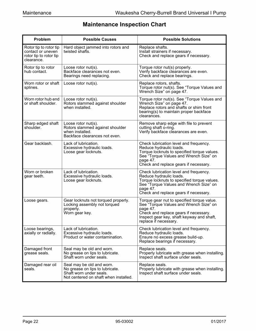
Maintenance Inspection Chart
.
Problem Possible Causes Possible Solutions
Rotor tip to rotor tip contact or uneven rotor tip to rotor tip clearance.
Hard object jammed into rotors and twisted shafts.
Replace shafts. Install strainers if necessary. Check and replace gears if necessary.
Rotor tip to rotor hub contact.
Loose rotor nut(s). Backface clearances not even. Bearings need replacing.
Torque rotor nut(s) properly. Verify backface clearances are even. Check and replace bearings.
Worn rotor or shaft splines.
Loose rotor nut(s). Replace rotors, shafts. Torque rotor nut(s). See “Torque Values and Wrench Size” on page 47.
Worn rotor hub end or shaft shoulder.
Loose rotor nut(s). Rotors slammed against shoulder when installed.
Torque rotor nut(s). See “Torque Values and Wrench Size” on page 47. Replace rotors and shafts or shim front bearing(s) to maintain proper backface clearances.
Sharp edged shaft shoulder.
Loose rotor nut(s). Rotors slammed against shoulder when installed. Backface clearances not even.
Remove sharp edge with file to prevent cutting shaft o-ring. Verify backface clearances are even.
Gear backlash. Lack of lubrication. Excessive hydraulic loads. Loose gear locknuts.
Check lubrication level and frequency. Reduce hydraulic loads. Torque locknuts to specified torque values. See “Torque Values and Wrench Size” on page 47. Check and replace gears if necessary.
Worn or broken gear teeth.
Lack of lubrication. Excessive hydraulic loads. Loose gear locknuts.
Check lubrication level and frequency. Reduce hydraulic loads. Torque locknuts to specified torque values. See “Torque Values and Wrench Size” on page 47. Check and replace gears if necessary.
Loose gears. Gear locknuts not torqued properly. Locking assembly not torqued properly. Worn gear key.
Torque gear nut to specified torque value. See “Torque Values and Wrench Size” on page 47. Check and replace gears if necessary. Inspect gear key, shaft keyway and shaft, replace if necessary.
Loose bearings, axially or radially.
Lack of lubrication. Excessive hydraulic loads. Product or water contamination.
Check lubrication level and frequency. Reduce hydraulic loads. Ensure no excess grease build-up. Replace bearings if necessary.
Damaged front grease seals.
Seal may be old and worn. No grease on lips to lubricate. Shaft worn under seals.
Replace seals. Properly lubricate with grease when installing. Inspect shaft surface under seals.
Damaged rear oil seals.
Seal may be old and worn. No grease on lips to lubricate. Shaft worn under seals. Not centered on shaft when installed.
Replace seals. Properly lubricate with grease when installing. Inspect shaft surface under seals.
Page 22 95-03002 01/2017

Waukesha Cherry-Burrell Brand Universal I Pump Maintenance
Annual Maintenance DANGER: The pump contains internal moving parts. DO NOT put hands or fingers into the pump body ports or drive area at any time during operation. To avoid serious injury, DO NOT install, clean, service, or repair the pump unless all power is off and locked out.
At least annually, perform the procedures and corrective measures outlined in “Maintenance Inspections” on page 20, in addition to the following preventive maintenance:
• Check the bearings with a dial indicator for shaft radial play (Figure 29). If the deflection is equal to or greater than the rotor-to-body diametrical clearance (“Checking for Proper Clearance” on page 40), replace the bearings.
• Remove the gear cover and inspect the gears for wear, backlash and looseness. Loosen and torque the gear retaining nuts to the proper torque. See Table 4 on page 47.
• Thoroughly inspect the rotors for worn keyways, hub wear and stress cracks (Figure 30, item A). Use the dye check method to detect any fatigue-type cracks at rotor stress points.
• Review the performance record on the pump, and check the radial and backface clearances to determine wear and effect on performance. See Table 2, “Rotor Clearances,” on page 41. Adjustment to the operating speed can compensate for wear in some applications.
CAUTION: When bearings or shafts are replaced in the field, take care to correctly position the shaft by shimming it to maintain sufficient running clearances between the rotor wing faces and the pump body faces (backface and cover face). It is important to hold the same backface dimension for both rotors to avoid crossover interference.
Cleaning Use a basket or wash tank with a rubber mat covering the bottom. Wash the parts thoroughly with a cleaning compound using brushes and plenty of fresh warm water at about 125°F (52°C). Rinse the parts thoroughly with 170°F (77°C) water and store them to permit free draining and natural drying. Reassemble the pump and sterilize it in accordance with accepted sterilizing practices. If a chlorine solution (200 ppm available chlorine) is used, it should leave no residual deposits which would remain in the pump.
NOTE: Acid cleaners have a much higher metal corrosion rate and pump parts should remain in acid cleaning solutions no lon-ger than necessary. Any strong inorganic mineral-based acids that are harmful to your hands would be harmful to pump parts. Due to the high circulation required, SPX FLOW recommends that its pumps not be used to recirculate cleaning solutions.
Figure 29 - Check bearings
Figure 30 - Rotor Stress Points
01/2017 95-03002 Page 23

Maintenance Waukesha Cherry-Burrell Brand Universal I Pump
Fluid Head Disassembly (All Models)
DANGER: The pump contains internal moving parts. DO NOT put hands or fingers into the pump body ports or drive area at any time during operation. To avoid serious injury, DO NOT install, clean, service, or repair pump unless all power is off and locked out.
DANGER: To avoid serious injury, shut off and drain product from the pump prior to disconnecting the piping.
Remove Cover1. Remove the cover wing nuts from the cover using a soft
hammer to loosen them (Figure 31).
2. Remove the cover. If it is stuck, loosen it with a soft hammer. Remove and discard the cover o-ring (Figure 32).
3. Place the cover on a protected surface with the finished surfaces facing up.
4. Remove the rotor retaining nuts. Use the special wrench supplied with the pump and hit the handle sharply with a soft hammer to loosen the nuts (Figure 33).
5. Orient the rotors perpendicular to each other and remove the rotor with both wings exposed first. Handle the rotors with care to avoid nicks and scratches. If the rotor is stuck tight, use a gear puller or hardwood lever behind the rotor hub to force it off the spline (Figure 34).
6. Remove the pump body by pulling it straight off the studs (Figure 35). Use a soft hammer to assist if the body is stuck tight.
7. See “Seal Maintenance” on page 26 for the seal disassembly procedure.
8. Clean and inspect the body thoroughly.
CAUTION: The body must be reassembled on the bearing housing from which it was removed. Both are identified with the same serial number.
Figure 31 - Remove Cover Nuts
Soft Hammer
Figure 32 - Rmove O-Ring
O-Ring
Figure 33 - Remove Rotor Retaining Nuts
Figure 34 - Apply Gear Puller
Apply gear puller here
Figure 35 - Remove Pump Body
Page 24 95-03002 01/2017

Waukesha Cherry-Burrell Brand Universal I Pump Maintenance
Model 320 and 324 Body Disassembly
After removing the cover and rotors, remove the four bolts from each seal gland and slide the gland toward the gear case. Loosen the two socket head cap screws from the front of the body. Tap the body with a soft hammer to drive the body loose from the gear case and dowel pins.
Model 323 Aseptic Body Disassembly
1. Disconnect the flushing lines.
2. Remove the cap screws from the seal flush glands and slide the glands back against the gear case.
3. Loosen the two socket head cap screws in the front of the body. Tap the body with a soft hammer to drive the body loose from the gear case and dowel pins.
4. Thoroughly clean the shafts. If the shaft shoulder has a sharp edge, remove the edge with a file to prevent cutting the shaft o-ring when disassembling the seal seat.
Figure 36 - Remove Cap Screws
Cap screw (2)Gland Bolts (8)
Figure 37 - Remove Pump Body
Figure 38 - Clean Shafts
Shaft Shoulder (file here if necessary)
01/2017 95-03002 Page 25

Maintenance Waukesha Cherry-Burrell Brand Universal I Pump
Seal Maintenance NOTE: To service the seals, first disassemble the fluid head. See “Fluid Head Disassembly (All Models)” on page 24.
O-Ring Service
1. Remove and discard the body o-rings, using the o-ring removal tool furnished with the pump.
2. Remove shaft sleeves and shaft o-rings.
3. Thoroughly clean and inspect grooves, shafts and sleeves. DO NOT re-use sleeves that are grooved or scratched.
Assembly
1. Apply an approved o-ring lubricant to the NEW o-rings and insert them into the body grooves and shaft grooves. The shaft o-rings should be installed into the front shaft groove (closest to the shaft spline) when using o-ring seals. Sleeves may be either slotted or have prongs.
2. Assemble the shaft sleeves against the shaft shoulder, making sure that the sleeve prongs DO NOT line up with the drive pin on the shaft. However, do place the slotted sleeve over the pin if you have that type of sleeve.
3. See page 43 for fluid head assembly procedure.
Double O-RingService
1. Remove the o-ring carriers.
2. Remove and discard the o-rings from both the body and carriers, using the o-ring removal tool furnished with pump.
3. Remove the shaft sleeves and shaft o-rings.
4. Thoroughly clean and inspect the body, carrier and shaft grooves, and sleeves.
NOTE: DO NOT re-use sleeves that are grooved or scratched.
Figure 39 - Remove O-Rings
Body O-Ring
Shaft O-Ring
Figure 40 - Remove Shaft Sleeve
Drive Pin Sleeve
Shaft O-Ring
Figure 41 - Shaft Sleeves
Prongs Slotted
Figure 42 - Assemble Shaft Sleeves
Sleeve
Figure 43 - Double O-Ring
Carrier O-Rings
Body O-Ring
Shaft O-RingSleeve
Page 26 95-03002 01/2017

Waukesha Cherry-Burrell Brand Universal I Pump Maintenance
Assembly
1. Apply an approved o-ring lubricant to the NEW o-rings and insert them into body, carriers and shaft grooves. Install the shaft o-rings into the front shaft groove (closest to the shaft spline) when using o-ring seals.
2. Assemble the carriers into the body so that the notch in the carrier engages the pin in the body.
3. Assemble the shaft sleeves against the shaft shoulder, making sure that the sleeve prongs DO NOT line up with the drive pin on the shaft.
4. See page 43 for fluid head assembly procedure.
Mechanical Seal
Service - Single Inside
1. Remove the seal from the body, then clean and inspect it thoroughly. DO NOT re-use if the seal face is scratched, chipped or cracked.
2. Remove the o-rings from the body and discard them. Use the o-ring removal tool supplied with pump.
3. If the shaft shoulder has a sharp edge, remove the edge with a file to prevent cutting the shaft o-ring when disassembling the seal seat. See Figure 47.
4. Remove the seal seats and shaft o-rings. Clean and inspect them thoroughly. DO NOT re-use seats that are cracked, chipped, scratched or grooved.
Assembly - Single Inside
1. Install NEW o-rings on the shafts. Lubricate the o-rings to aid in assembly of the seal seat.
2. Install the seal seats, making sure to line up the groove on the rear face with the drive pin on the shaft. Lubricate the face of the seat.
3. Lubricate and insert the NEW o-rings in the body grooves.
Figure 44 - Assemble Carriers into Body
Seal Carrier Pump Body
Figure 45 - Remove Shaft Sleeve
Drive Pin Sleeve
Shaft O-Ring
Figure 46 - Mechanical Seal
Seal Seat
Inner Seal
O-Ring
Figure 47 - Shaft Shoulder
Shaft Shoulder (file here if necessary)
Figure 48 - Install O-Rings
Shaft O-Ring
Drive PinSeal Seat
01/2017 95-03002 Page 27

Maintenance Waukesha Cherry-Burrell Brand Universal I Pump
4. Assemble the wave spring on the seal and install it into the body with the notch engaging the pin in the body.
5. Lubricate the seal faces.
6. See page 43 for fluid head assembly procedure.
Service - Single Outer
1. Remove the seals from the body and discard the o-rings. Inspect the seal face thoroughly. DO NOT re-use seals that are cracked, chipped or scratched.
2. If the shaft shoulder has a sharp edge, remove the edge with a file to prevent cutting the shaft o-ring when disassembling the seal seat.
3. Remove the seal seats and shaft o-rings. Clean and inspect them thoroughly. DO NOT re-use seats that are cracked, chipped, scratched, or grooved.
Assembly - Single Outer
1. Install the NEW o-rings on the shafts and lubricate them to aid in assembly of the seal seat.
2. Install the seal seats, making sure to line up the groove on the rear face with the drive pin on the shaft. Lubricate the face of the seat.
3. Apply lubricant to the NEW o-rings for the seal and assemble them on the seals.
4. Insert the seal assembly into the body, engaging the notch with the pin. Push from the opposite side, over and in, to seat the o-ring.
5. Apply lubricant to the seal face.
6. See page 43 for fluid head assembly procedure.
Figure 49 - Assemble Wave Spring
Inner Seal Body O-Ring
Wave Spring
Figure 50 - Remove Seals
Outer Seal
O-RingSeal Seat
Figure 51 - Shaft Shoulder
Shaft Shoulder (file here if necessary)
Figure 52 Install O-Rings
Shaft O-Ring
Drive PinSeal Seat
Figure 53 - Insert Seal Assembly
Pin
OuterSeal
Page 28 95-03002 01/2017

Waukesha Cherry-Burrell Brand Universal I Pump Maintenance
Double Concentric Seals and Aseptic Model SealsService - Outer Seal
Remove the seals from the body and discard the o-rings. Inspect the seal face thoroughly. DO NOT re-use seals that are cracked, chipped or scratched.
Service - Inner Seal
1. Remove seal from body, then clean and inspect thoroughly. DO NOT re-use if seal face is scratched, chipped or cracked.
2. Remove o-rings from body and discard. Use o-ring removal tool supplied with pump.
3. If the shaft shoulder has a sharp edge, remove the edge with a file to prevent cutting the shaft o-ring when disassembling the seal seat.
4. Remove seal seats and shaft o-rings. Clean and inspect thoroughly. DO NOT re-use seats that are cracked, chipped, scratched or grooved.
Assembly - Outer Seal
1. Install new o-rings on shafts and lubricate to aid in assembly of seal seat.
NOTE: On aseptic models, there are 2 o-rings per shaft.
2. Install seal seats, being sure to line up groove on rear face with drive pin on shaft. Lubricate face of seat.
3. Apply lubricant to NEW o-rings for seal and assemble on seals.
4. Insert seal assembly into body engaging notch with pin and pushing from opposite side, over and in, to seat o-ring.
5. Apply lubricant to seal face.
Assembly - Inside Seal
1. Lubricate and insert NEW o-rings in body grooves.
2. Assemble wave spring on seal and install into body with notch engaging pin in body.
3. Lubricate seal faces.
4. See page 43 for fluid head assembly procedure, seals with a cracked, chipped or scratched seal face.
Figure 54 - Insert Seal Assembly
Seal Seat Spring
“O” Ring
Inner SealOuter Seal
Figure 55 - Shaft Shoulder
Shaft Shoulder (file here if necessary)
Figure 56 - Install O-Rings
Shaft O-Ring
Drive PinSeal Seat
Figure 57 - Install Seal Seats
BodyO-Ring
Pin
Seal
Figure 58 - Insert O-Rings
Body O-RingPin
Wave Spring
01/2017 95-03002 Page 29
Maintenance Waukesha Cherry-Burrell Brand Universal I Pump
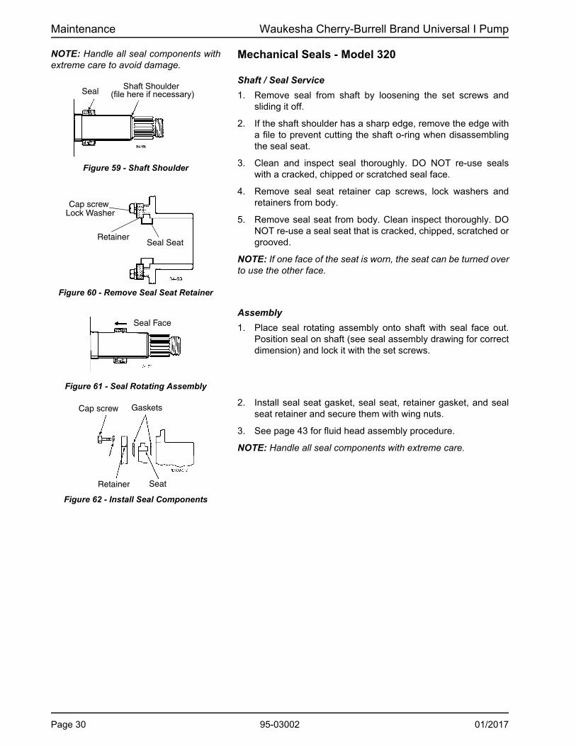
NOTE: Handle all seal components with extreme care to avoid damage.
Mechanical Seals - Model 320
Shaft / Seal Service
1. Remove seal from shaft by loosening the set screws and sliding it off.
2. If the shaft shoulder has a sharp edge, remove the edge with a file to prevent cutting the shaft o-ring when disassembling the seal seat.
3. Clean and inspect seal thoroughly. DO NOT re-use seals with a cracked, chipped or scratched seal face.
4. Remove seal seat retainer cap screws, lock washers and retainers from body.
5. Remove seal seat from body. Clean inspect thoroughly. DO NOT re-use a seal seat that is cracked, chipped, scratched or grooved.
NOTE: If one face of the seat is worn, the seat can be turned over to use the other face.
Assembly
1. Place seal rotating assembly onto shaft with seal face out. Position seal on shaft (see seal assembly drawing for correct dimension) and lock it with the set screws.
2. Install seal seat gasket, seal seat, retainer gasket, and seal seat retainer and secure them with wing nuts.
3. See page 43 for fluid head assembly procedure.
NOTE: Handle all seal components with extreme care.
Figure 59 - Shaft Shoulder
SealShaft Shoulder
(file here if necessary)
Figure 60 - Remove Seal Seat Retainer
Cap screwLock Washer
RetainerSeal Seat
Figure 61 - Seal Rotating Assembly
Seal Face
Figure 62 - Install Seal Components
Cap screw Gaskets
Retainer Seat
Page 30 95-03002 01/2017

Waukesha Cherry-Burrell Brand Universal I Pump Maintenance
Mechanical Seals - Model 323 Aseptic (323A)Service
1. Remove inner seal by disengaging set screws in seal collar.
2. Slide inner seal, seal seat and gaskets off shaft.
3. Loosen outer seal set screws and pull seals off shafts. Remove burrs on shafts where set screws locked to aid in reassembly.
4. Clean and inspect all seal components thoroughly. DO NOT re-use a seal or seal seat that is cracked, scratched or grooved.
Assembly
1. Slip outer seals onto shafts and secure them in position with set screws. See seal drawing for mounting dimension.
2. Slide seal seat retainer, retainer gasket, seal seat, and seat gasket, in that order, onto shafts and place seal seat against the seat face of outer seal.
3. Install inner seal with seal face against seal seat and lock in position with set screws. See seal drawing for mounting dimension.
NOTE: Handle all seal components with extreme care
4. Mount pump body onto bearing housing and be sure seal seats are located in body counterbores. Secure body with 4 bolts.
5. Place seal seat retainer and retainer gaskets in position and secure with cap screws.
Figure 63 - Remove Inner Seal
Inner SealSeal Collar
Set Screw
Figure 64 - Install Seal Components
Seal Inner
Outer Seal Gaskets
Seal RetainerSeat Seal
Figure 65 - Install Inner Seal
Retainer
Seal Seat
Gaskets
Figure 66 - Mount Pump Body
Inner Seal
Figure 67 - Position Seal Retainer
Seal Seat
Retainer
BodyBolt
Cap Screw
01/2017 95-03002 Page 31

Maintenance Waukesha Cherry-Burrell Brand Universal I Pump
Gear Case Disassembly DANGER: To avoid serious injury, DO NOT install, clean, service, or repair the pump unless all power is off and locked out.
DANGER: To avoid serious injury, shut off and drain product from the pump prior to disconnecting piping.
Remove Gear Case Cover1. Remove the oil drain plug (Figure 68, item 24D); drain the oil.
2. Remove the cap screws from the gear case (Figure 68, item33A).
3. Pull the cover (item 4) off the shaft extension. If the cover sticks, use a soft hammer to loosen it.
4. Remove the silicone sealant (item 25) from the gear case and cover.
5. Using an arbor press, remove the oil seal (item 12) from the cover. Discard the used oil seal.
6. Straighten the tab on the lock washers (Figure 69, item A).
Remove Shaft1. Prevent the shafts from turning by placing a wedge between
the gears (Figure 70, item A).
NOTE: Protect the liquid end of the shafts by wrapping them with tape. See Figure 71 and Figure 73.
2. Use a spanner wrench or drift punch to remove the gear lock nut. The gears will be removed later.
3. Remove the front bearing retainer screws and pull off the bearing retainers (Figure 71). If a retainer is stuck, leave it in place; it will press out when the shaft is removed.
Figure 68 - Remove Gear Case Cover
3. Gear Case4. Gear Case Cover12. Oil Seal24D. Oil Drain Plug24F. Oil Fill Plug
24L. Oil Level Check Plug, Sight glass
25. Silicone Sealant33A. Cap Screw
PD100-056
12
33A 4
3
24D
24F
24L25
Figure 69 - Straighten Lock Tab
PD100-057
A
A
Figure 70 - Block Shaft Rotation
PD100-058
A
Figure 71 - Remove Bearing Retainers
Retainer Tape
Retainer CapSiliconeSealant
Screw
Page 32 95-03002 01/2017

Waukesha Cherry-Burrell Brand Universal I Pump Maintenance
4. Remove the silicone sealant (Figure 72, item A) from the bearing retainer and gear case.
NOTE: Protect the liquid end of the shafts by wrapping them with tape.
5. Place the gear case on an arbor press with the liquid end facing down. Protect the shaft ends with a wood or plastic block (Figure 73) and press the shafts out of the gear case. See Table 5, “Arbor or Hydraulic Press Required (Tons),” on page 47.
6. Press out and discard the front bearing seals from the front bearing retainers. Clean and reuse the bearing isolators, if installed.
7. Remove the shims. If the shafts and bearings will be reused, identify the shims and bearings that belong with each shaft.
8. Press out and discard both rear oil seals in the gear case (Figure 75, item 13).
. 9. Use a hydraulic press and V-blocks (Figure 76, item B) to remove the bearings (items 15 and 16) and spacer (item 30)
NOTE: Make sure both ends of the shaft are protected when removing the shaft.
Figure 72 - Remove Sealant from Retainer
Figure 73 - Press Shafts from Gear Case
Block to PreventShaft Damage
Tape
Figure 74 - Remove Rear Oil Seals
Front Bearing Seal Bearing
Retainer
SiliconeSealant
Figure 75 - Remove Rear Oil Seals
Figure 76 - Remove Bearings from Shaft
01/2017 95-03002 Page 33

Maintenance Waukesha Cherry-Burrell Brand Universal I Pump
Shaft Assembly Front Bearing Assembly
NOTE: SPX FLOW now offers shaft assemblies with pressed-on bearings. See page 103.
SPX FLOW PD Precision Pumps require bearing assemblies with very tight internal tolerances. In fact, the internal tolerances of “off-the-shelf” bearings can be many times larger than required. Although they are considered in-spec in the bearing industry, they can cause internal damage within an SPX FLOW PD Pump.
SPX FLOW’s proprietary bearing “MATCHING” process starts with top quality bearing assemblies, then sorts, measures, pairs, grinds and adds spacers to them to ensure the matched bearing sets meet the required tight internal tolerances.
SPX FLOW bearings can be cross-referenced and appear to be the same, but competitive bearings are omitting the Matching process, which is imperative to achieve the required internal tolerances. Once a bearing set is matched, it must remain together as a set for the life of the pump, in order to maintain the tight internal tolerances.
The following instructions cover the assembly of a six-piece front bearing assembly. For a four-piece assembly, only one spacer and cup is used.
1. Lubricate the front bearing area of the shaft (Figure 77, item 7, 8) with oil or grease. Place it upright in a hydraulic press with the liquid end down.
2. Unwrap the front bearing assembly.
NOTE: DO NOT interchange the parts of one bearing assembly with another. The parts are precisely matched during manufactur-ing and must be installed as a matched assembly. See Figure 78.
3. Lift the lower cone and roller assembly (Figure 78, item A) out of the bearing stack and place it on the shaft with the radius facing down. Press it onto the shaft until it is seated against the shaft shoulder. Press only on the inner cone.
Figure 77 - Grease Shaft
Figure 78 - Bearing Assembly
A. Lower Cone / Roller Assembly
B. Inner SpacerC. Lower Cup
D. Outer SpacerE. Upper CupF. Upper Cone /
Roller Assembly
Figure 79 - Press Lower Cone onto Shaft
Page 34 95-03002 01/2017

Waukesha Cherry-Burrell Brand Universal I Pump Maintenance
4. Place the inner spacer (Figure 80, item B) over the shaft onto the lower cone and roller assembly.
5. Place the lower cup (item C) over the lower cone and roller assembly, keeping the cup opening toward the assembly.
6. Place the outer spacer (item D) over the shaft and onto the lower cup.
7. Place the upper cup (Figure 81, item E) on top of the outer spacer.
8. Lubricate the remaining upper cone and roller assembly (Figure 81, item F) with oil or grease and slip it over the shaft with the roller radius facing up. Press it onto the shaft and into the upper cup.
NOTE: Make sure all components are aligned before pressing. Press only on the inner cone.
9. Install the bearing spacer (Figure 82, item 30).
Figure 80 - Install Inner & Outer Spacer, Lower Cup
Figure 81 - Install Upper Cup & Upper Cone
Figure 82 - Install Bearing Spacer
01/2017 95-03002 Page 35

Maintenance Waukesha Cherry-Burrell Brand Universal I Pump
Rear Bearing Assembly Models 006, 014, 015, 018, 024, 030, 033A, 034 use a single ball bearing assembly for the rear bearing. All other models use a tapered roller bearing assembly similar to the front bearings.
1. Unwrap the rear bearing assembly.
NOTE: DO NOT interchange the parts of one bearing assembly with another. These parts are precisely matched during manufac-turing and must be installed as a matched assembly.
• For models with ball bearing assemblies: Lubricate the shaft inner bearing race with oil or grease. Press the bearing into place. The shielded side of the bearing fits against the bearing spacer. Press only on the inner race.
• For models with tapered roller bearing assemblies: Lubricate the shaft bearing area with oil or grease. Follow the “Front Bearing Assembly” procedures on page 34.
NOTE: Heating the bearings is NOT recommended. If bearings are heated, do not exceed 300°F (149°C).
Figure 83 - Rear Tapered Roller Bearing Assembly
Page 36 95-03002 01/2017

Waukesha Cherry-Burrell Brand Universal I Pump Maintenance
Gear Case Assembly Shimming1. When installing the shafts in the gear case, shim behind the
front bearing to achieve the proper backface clearance between the back of the rotors and the body. The backface clearance must be equal for both rotors to prevent the rotors from hitting each other during operation.
NOTE: Do not install bearing retainer sealant, gears, or gear locknuts until the correct shimming has been verified.
2. If the shafts and/or bearings do not need to be replaced and the shims are marked indicating the shaft and bearing they are matched with, a shim adjustment probably will not be necessary. Reuse the existing tagged shims, shafts and bearings in the same gear case bores.
3. If existing shims are lost and/or a standard shaft is used, determine the required shims from the chart.
4. If it is necessary to calculate the required shims for replacement shafts, bearings or both, refer to Figure 84and Figure 85; carry measurements and calculations to three decimal places (i.e. 0.059).
NOTE: Arrange with thicker shims on outside of the shim pack.
5. Determine the shim thickness required for the front bearing:
• Measure “B” in the gear case and “C” on the shaft (Figure 84).
• Measure “D” and “E” on the body (Figure 85).
• Determine the proper backface clearance. Refer to Table 2, “Rotor Clearances,” on page 41.
• Required Shims = Backface clearance - C + B + D - E.
6. Place the shims in the body, resting against the shoulder in the front bearing bore.
Gear CaseFront Face
shim thickness
Figure 84 - Measure B and C Figure 85 - Measure D and EB. Front face of gear case to back of bearing bore
C. Shaft shoulder to back of bearing race
D. Body thickness
E. Depth of rotor cavity
Suggested Shims
UI ModelStd.
Shaft
Replace-mentShaft
Shimkit
006, 014, 015, 018,
024
0.113 in(2.87 mm)
0.110 in(2.79 mm) 117889+
030, 033A,
034, 040
0.105 in(2.27 mm)
0.102 in(2.59 mm) 117890+
060, 064, 130,
133A, 134
0.093 in(2.36 mm)
0.088 in(2.24 mm) 117891+
220, 223A, 224
0.115 in(2.92 mm)
0.110 in(2.79 mm)
117892+
320 0.125 in(3.18 mm)
0.120 i (3.05 mm)
117893+
01/2017 95-03002 Page 37

Maintenance Waukesha Cherry-Burrell Brand Universal I Pump
Install Shaft1. With the shims in place, install the shaft assembly in the front
bearing bore with the fluid end facing up. Ensure that the shaft is installed in its original location.
NOTE: The shafts may need to be removed for a final shim adjustment.
2. Lubricate the outside diameter of the bearing.
3. Press the shaft into place until it is seated against the shim pack. Press only against the outer race of the bearing.
NOTE: A tube of the same diameter as the outer race of the bear-ing also can be used to press the shaft into place.
4. Temporarily secure the shaft/bearing in place with bearing retainers to aid in checking the clearances. DO NOT install silicone sealant at this time.
5. The bearing retainer must rest firmly against the bearing. Leave a 0.010 to 0.050 in (0.25 to 1.25 mm) clearance between the back of the bearing retainer and the front of the gear case (Figure 86). If this clearance is not met, place shims between the bearing and retainer.
6. Temporarily mount the body on the gear case.
7. Secure the body to the gear case using the body retaining screws.
8. Install the rotors and rotor nuts. Rotor nut o-rings and retainer o-rings are not required at this time.
9. Measure the rotor backface clearance (Figure 87, item A) through the port or from the front. The backface clearance for both rotors must be the same to prevent rotor crossover contact and must be ±.0005" of the value found in Table 2, “Rotor Clearances,” on page 41.
10. Check the rotor front face clearance (Figure 87, item C).
11. Check the rotor to body clearance (Figure 87, item B).
12. Check the clearances against Table 2, “Rotor Clearances,” on page 41. For other non-standard rotors, check with the factory.
NOTE: “B” dimension is below the face of the casing.
NOTE: If the process uses special clearance rotors, contact the factory with the serial number of the pump for clearance tolerance values.
13. If the backface clearance is not met, disassemble the pump and adjust the shimming to achieve the correct backface clearance.
14. If the rotor to body clearance is not met or is uneven, contact SPX FLOW technical services for proper adjustment procedures.
15. After obtaining proper clearance, remove the rotor nuts, rotors, body, and bearing retainers.
Figure 86 - Bearing Retainer Clearance
Figure 87 - Measure Clearance
Page 38 95-03002 01/2017

Waukesha Cherry-Burrell Brand Universal I Pump Maintenance
16. Grease the front and rear bearing through the grease fittings until grease is visible around the bearing assemblies. The amount of grease required is listed in “Grease Quantity (per Bearing)” on page 19. Rotate the shafts while greasing to disperse the grease.
17. Lubricate the seal lips and install the grease seals in the bearing retainers (compression spring on inside).
18. Coat the retainer flanges with silicone sealant (Figure 88, item A). (Gore-Tex® sealing tape can be used on silicone free models.) The grease seal (item 14) will be flush with the front of the bearing retainer. On 030 models, the grease seal will be against the step on the inside diameter of the retainer.
19. Install the bearing retainers (Figure 88, item 32).
Install Rear Seal AssemblyNOTE: Place tape or other material over the shaft end to prevent cutting the seal during installation.
1. Install the gear spacers (Figure 89, item 29).
2. Lubricate the inside and outside diameters of the oil seals with oil or grease.
3. Install the oil seals with the spring facing out (Figure 89, item13).
Install Timing Gears1. Place the gear keys into the shaft key slots. Angle the keys
out for easier installation of the gears.
NOTE: To aid in timing setup, rotate the rotors until they are at right angles to each other before installing the gears.
2. Slide the spur drive gear onto the drive shaft. The spur drive gear has one punch mark on the gear.
3. Slide the short shaft gear onto the short shaft. The short shaft gear has two punch marks on the gear. Straddle the single punch mark of the spur drive gear with the two punch marks on the short shaft gear (Figure 90).
4. Use a wood or nylon block (Figure 91, item A) to keep the shafts from turning. If a block is not available, use rags to block the gears, or with one rotor on the shaft, block the rotor with a nylon dowel.
5. Slide the lock washers onto the shaft. Lubricate the threaded area on the shafts and face of the locknuts with oil or grease.
Figure 88 - Install Bearing Retainer
Figure 89 - Install Rear Seal
Figure 90 - Timing Gear Marks
Figure 91 - Block Shaft Rotation
PD100-058
A
01/2017 95-03002 Page 39

Maintenance Waukesha Cherry-Burrell Brand Universal I Pump
6. Tighten the gear locknuts using a spanner wrench or drift.
7. Bend the locking tab (Figure 93, item A) on the lock washers into the locking nut slots, securing the gear locknut into place.
Checking for Proper ClearanceWaukesha Cherry-Burrell brand pumps are designed with close running clearances. Backface clearances are set with shims during assembly.
Shafts are positioned with shims behind the front bearing and locked into gear case with the bearing retainers. Rotors lock against the shaft shoulder. Clearance between the body backface and the back of the rotor wing is called backface clearance.
NOTE: It is good practice to keep back-face clearance to a minimum.
1. To check backface clearance, first mount the body (less seals) onto the housing. Assemble the rotors and secure them with rotor jam nuts.
CAUTION: Backface clearance for both rotors must be equal to avoid crossover interference with the adjacent rotor hub.
2. With feeler gauges, measure the rotor backface clearance (Figure 94, item A), through the port or from the front.
Figure 94 - Clearance Measurements
Front BearingRearShim
BackfaceClearance
Rotor to BodyClearance
PumpBody
Front Face
A
B
CClearance
3. Measure the rotor front face clearance (Figure 94, item C).
Figure 92 - Install Gear Locknuts
Figure 93 - Bend Locking TabPD100-057
A
A
Page 40 95-03002 01/2017

Waukesha Cherry-Burrell Brand Universal I Pump Maintenance
4. Measure the rotor to body clearance (Figure 94, item B).
5. Check the measured clearances against Table 2, “Rotor Clearances,” on page 41.
6. Make corrections as required and follow examples in Table 3, “Backface Clearance Corrections,” below, to determine the exact adjustment to make and to avoid unnecessary assembly/disassembly.
7. To make shim adjustments, first remove the rotors, body and shafts. Make the required shim adjustment and reassemble.
8. Re-check the backface clearances. Be sure both rotors have the same clearance to avoid crossover interference with the adjacent rotor hub.
Table 2: Rotor Clearances
Universal I Model
Rotor Type: Std & FF Hot Std & FF Hot Standard FF & Hot.0015 - .002 in .0015 - .002 in .001 - .004 in .0025 - .0055 in .004 - .006 .0055 - .0075 in
(.04 - .05 mm) (.04 - .05 mm) (.03 - .10 mm) (.06 - .14 mm) (.10 - .15 mm) (.14 - .19 mm)
.0015 - .002 in .0015 - .002 in .001 - .004 in .0025 - .0055 in .004 - .0065 in .006 - .0085 in
(.04 - .05 mm) (.04 - .05 mm) (.03 - .10 mm) (.06 - .14 mm) (.10 - .17 mm) (.15 - .22 mm)
.002 - .0025 in .002 - .0025 in .001 - .005 in .0025 - .006 in .0035 - .006 in .0065 - .009 in
(.05 - .06 mm) (.05 - .06 mm) (.03 - .13 mm) (.06 - .15 mm) (.09 - .15 mm) (.17 - .23 mm)
.003 - .0035 in .003 - .0035 in .003 - .0075 in .005 - .010 in .0045 - .009 in .0085 - .014 in
(.08 - .09 mm) (.08 - .09 mm) (.08 - .19 mm) (.13 - .25 mm) (.11 - .23 mm) (.22 - .36 mm)
.003 - .0035 in .003 - .0035 in .0035 - .0075 in .0055 - .0095 in .0045 - .009 in .009 - .015 in
(.08 - .09 mm) (.08 - .09 mm) (.09 - .19 mm) (.14 - .24 mm) (.11 - .23 mm) (.23 - .38 mm)
.004 - .005 in .004 - .005 in .0055 - .0095 in .009 - .013 in .005 - .010 in .010 - .015 in
(.10 - .13 mm) (.10 - .13 mm) (.14 - .24 mm) (.23 - .33 mm) (.13 - .25 mm) (.25 - .38 mm)
.005 - .006 in .005 - .006 in .008 - .012 in .010 - .014 in .007 - .012 in .013 - .018 in
(.13 - .15 mm) (.13 - .15 mm) (.20 - .30 mm) (.25 - .36 mm) (.18 - .30 mm) (.33 - .46 mm)PD100-598a
Standard Rotors: -40°F (-40°C) to 180°F (82°C); FF Clearance Rotors: 180°F (82°C) to 200°F (93°C); Hot Clearance Rotors: -40°F (-40°C) to 300°F (149°C). Contact SPX FLOW Application Engineering if alternate rotors are needed.
060, 064
133A, 130, 134
220, 223A, 224
320, 323A, 324
Std = Standard Clearance Rotors; FF = Front Face Clearance Rotors; Hot = Hot Clearance Rotors
030, 033A, 034, 040
A - Back Facein (mm)
B - Rotor to Bodyin (mm)
C - Front Facein (mm)
006
014, 015, 018, 024
NOTE: The assembly clearances stated above are for reference only. Actual pump clearances may vary based on pump performance testing.
NOTE: If the clearance corrections in Table 3 have been performed and desired performance is not achieved, contact SPX FLOW technical services for guidance.
Table 3: Backface Clearance Corrections
Problem Condition Correction
Too Much Backface Clearance (A)
Dimension A is greater than the value in Table 2
A (measured) minus Column A (Table 2) = shims to remove from the rear outer race of the front bearing
Rotor wing face projects past the body front face
C (measured with depth micrometer) plus C (Table 2) = shims to remove from the rear of the front bearing
Not Enough Backface Clearance (A)
Dimension A is less than the value in Table 2)
Column A (Table 2) minus A (measured) = shims to add to the rear outer race of the front bearing
01/2017 95-03002 Page 41

Maintenance Waukesha Cherry-Burrell Brand Universal I Pump
Install Gear Case Cover1. Lubricate the inside diameter of a new oil seal.
2. Press the new oil seal (Figure 95, item 12) into the gear case cover (item 4) flush with the outside face, with the spring facing in.
3. Apply silicone sealant to the back of the gear case. (Gore-Tex® sealing tape can be used on silicone-free models.) Place tape on the inside of the screw holes. (Figure 96, item A).
4. Tape the shaft end to prevent cutting the seal on the keyway. Mount the cover assembly on the gear case. Secure it with cap screws and washers.
5. Remove the tape from the shaft end.
NOTE: Make sure that the shaft is centered in the lip seal before securing the cap screws.
6. Install the oil drain plug.
7. Fill gear case with gear oil to proper level. Refer to “Lubrication” on page 19.
Figure 95 - Orientation of Oil Seal
Figure 96 - Sealant Placement
Page 42 95-03002 01/2017

Waukesha Cherry-Burrell Brand Universal I Pump Maintenance
Fluid Head Assembly Seal Assembly: See “Seal Maintenance” on page 26.
Body Assembly1. Slide the body over the shafts and studs, taking care that the
seal components are not nicked or knocked out of place. Press the body firmly against gear case, engaging the dowels.
2. On Model 320, 323A and 324, the bodies are secured to the gearcase with 2 socket head cap screws through the head. See “Seal Maintenance” on page 26.
Rotor Assembly
Assemble a rotor onto the shaft, engaging the large spline tooth with the large groove in the rotor. Rotate the shaft until the rotor wings are on a vertical centerline. Install the second rotor and secure both with rotor retaining nuts (clockwise). Lock the nuts. (See Table 4, “Torque Values and Wrench Size,” on page 47).
Cover Assembly1. Install the o-ring in the cover groove.
2. Mount the cover on the studs and push it against the body, making sure that the o-ring remains in the groove.
3. Attach the wing nuts (clockwise) and tighten by hitting them sharply with a soft hammer.
Figure 97 - Slide Body over Shafts
Figure 98 - Model 320, 323A and 324
Gear CaseSocket HeadCap Screw
Head
Figure 99 - Rotor Assembly
Figure 100 - Cover Assembly
Figure 101 - Attach Wing Nuts
01/2017 95-03002 Page 43

Maintenance Waukesha Cherry-Burrell Brand Universal I Pump
Relief Cover Option (Vented Cover)CAUTION: SPX FLOW does not recommend using a vented cover on liquids with a viscosity of over 5000 cPs.
The optional Relief Cover Feature (also called Vented Cover) is an adjustable, internal by-pass arrangement which can be used for control of the pressure and/or flow. It is bidirectional; that is, the pump flow or rotation can be in either direction.
NOTE: This option does not provide full flow relief for all pumping situations. The pressure downstream of the pump may increase with increasing amount of by-pass through the Relief Cover. Actual downstream pressure will depend on the pump speed, product viscosity, and the relief set point (spring adjustment or air pressure). Avoid high flow rates through the cover with high viscosity products. The resulting pressure may be greater than the maximum rating of the pump or other system components. Install a pressure gauge and measure the pressure under the worst conditions of maximum flow and maximum viscosity to determine the maximum pressure for your process. Under any conditions, if there is a complete flow shut off downstream, stop the pump as soon as possible. Continued pump operation with the entire flow by-passing will rapidly build heat within the pump body. Contact Waukesha Application Engineering for assistance.
Three types of Relief Covers are available:
Manual
By-pass pressure is adjusted by a threaded adjusting screw (2) which compresses a spring (5). Several spring sizes are available, to cover a range of operating pressures.
Pneumatic Diaphragm
By-pass pressure is adjusted by regulated air or gas pressure, operating on the side of a diaphragm (9) opposite the pumped fluid.
Pneumatic Piston
By-pass pressure is adjusted by regulated air or gas pressure, operating on the side of a metal piston (12), opposite the pumped fluid. An extended pressure range is possible.
NOTE: On all types of relief covers, the temperature and chemical resistance of the elastomer diaphragms and O-rings determine the useful range: Buna-N: Material supplied as standard Silicone Rubber: Optional material upon request
See page 100 for part numbers.
Figure 102 - Manual Vented Cover
Figure 103 - Pneumatic Vented Cover
Figure 104 - Piston Vented Cover
Page 44 95-03002 01/2017

Waukesha Cherry-Burrell Brand Universal I Pump Maintenance
Installation AdjustmentManual
Turn the adjusting screw counterclockwise to its farthest position, then clockwise until a light spring pressure is felt.
Pneumatic
1. Set air/gas pressure to 2-5 psig.
2. Turn on the pump.
A. With the pressure gauge and valve in the discharge line:
• Close the discharge valve.
• Turn the adjusting screw clockwise until the desired relief pressure registers on the gauge. Lock the adjusting screw with a lock nut.
• Open the valve in the discharge line. The relief cover is set and will open if the system pressure exceeds the preset limit.
B. Without a pressure gauge in the discharge line:
• Turn the adjusting screw clockwise and observe the product flow at the discharge of the system.
When the product flow reaches the maximum or desired flow rate, lock the adjusting screw with a lock nut.
Piston
1. With a pressure gauge and valve in the discharge line:
• Close the discharge valve slowly and observe the gauge pressure. DO NOT ALLOW PRESSURE TO EXCEED 200 psi.
• Increase the air/gas pressure, until the desired relief pressure registers on the gauge. Lock the air/gas pressure regulator adjusting screw with a lock nut.
• Open the valve in the discharge line.The relief cover is set and will open if the system pressure exceeds the preset limit.
2. Without a pressure gauge in the discharge line:
• With a regulator, increase the air/gas pressure to the relief valve and observe the product flow at the discharge of the system.
When the product flow reaches a maximum or desired flow rate, lock the regulator adjusting screw with a lock nut.
Figure 105 - Manual Adjustment
Figure 106 - Pneaumatic Adjustment
01/2017 95-03002 Page 45

Maintenance Waukesha Cherry-Burrell Brand Universal I Pump
Jacketed Cover Available on Models 006, 015, 018, 030, 040, 060, 130, and 220.
The jacketed cover is designed to allow circulation of a heating or cooling medium. The purpose is to help preheat or cool the pumping head and sustain operating temperature during short shut down periods. It should not be used as a heat exchanger to control pumping temperature during operation.
NOTE: Pressure limit for cover media is 60 PSI.
Pump Jackets
Split cast aluminum jackets with cast in pipe passages are available for higher pressures and temperatures. Consult factory for recommendations.
NOTE: Jacketed pumps require longer mounting studs in the gearcase. Use a special offset rotor wrench to remove rotors from 006 through 060 models to avoid hitting the studs. For part num-bers, see “Special Tools” on page 105.
Flushing Connection NOTE: Flushing media may be piped into either side for both shaft seals and discharged to drain on opposite side. Both inlets may be manifolded to simplify piping. Be sure flush water is flow-ing out both discharge lines.
Low Pressure Flush1. Set flow rate of approximately 1/4 GPM for most applications.
For high temperature applications increase flow.
2. Flushing media is restricted on inlet side and has free flow to drain on outlet side.
3. Typical flushing connections are 1/8" NPT female pipe taps.
Flushing Connection - Aseptic Series
All connections are 1/8" female pipe taps. The pump has double "barriers" or seals at every opening to the pump chamber. Live steam or a sterile fluid is circulated between these double seals at the ports, in the cover and at the shaft seals.
Figure 110 - Flushing Connections - Aseptic Series
Steam In
Steam Out
Steam Out
Steam Out
Steam In
Steam In
Steam Out
SteamIn
Figure 107 - Jacketed Cover
Model Number Pipe Tap
006, 015, 018, 030, 040 3/4"
060, 130, 220 1"
Figure 108 - Low Pressure Flush
Figure 109 - Flushing Connections
Restrictor
Flush In Flush Out
Flush In
Flush Out
Page 46 95-03002 01/2017

Waukesha Cherry-Burrell Brand Universal I Pump Maintenance
Table 4: Torque Values and Wrench Size
Universal I Model
Torque Values - Lock Nuts Wrench Size
Bearing Gear RotorBody Retaining
Cap Screw
006, 014, 015, 018, 024
--75 ft lbs102 N·m
30 ft lbs 41 N·m
3/16”
030, 033A, 034, 040 --100 ft lbs136 N·m
60 ft lbs 81 N·m
060, 064, 130, 133A, 134
150 ft lbs203 N·m
140 ft lbs 190 N·m
75ft lbs 102 N·m
1/4”
220, 223A, 224240 ft lbs325 N·m
230 ft lbs312 N·m
150 ft lbs 203 N·m
5/16”
320, 323A, 324360 ft lbs488 N·m
320 ft lbs 434 N·m
190 ft lbs 258 N·m
Reference Tables
Table 5: Arbor or Hydraulic Press Required (Tons)
Universal I ModelShaft Front Bearing
Rear Bearings
Housing Shaft
In Out On Off In Out On Off
006, 014, 015, 018, 024 0.25 0.5 0.5 1 0.5 1
014, 015, 018, 030, 033A, 034, 040
0.25 0.5 0.5 1 0.5 1
060, 064, 130, 133A, 134
0.5 1 2 5 3 5
220, 223A, 224 0.5 1 5 15 5 15
320, 323A, 324 0.5 1 5 20 5 20
01/2017 95-03002 Page 47

Maintenance Waukesha Cherry-Burrell Brand Universal I Pump
Standard O-Ring Selections, Descriptions and Color Codes for WCB Brand Pumps
Nitrile (Buna-N) (NBR)
Compound Color: Black
Color Code: Yellow
FDA Compliant to 21CFR177.2600
3A Sanitary
Silicone (Si)
Compound Color: Orange
Color Code: Black
FDA Compliant to 21CFR177.2600
3A Sanitary
Ethylene Propylene Diene Rubber (EPDM)
Compound Color: Black or Purple
Color Code: Green
FDA Compliant to 21CFR177.2600
Perfluoroelastomer (FFKM)
Compound Color: Black
Color Code: None
Individually packaged with size and material noted.
Ethylene Propylene Diene Rubber (Sulfur Free) (EPDM)
Compound Color: Black or Purple
Color Code: Blue
FDA Compliant to 21CFR177.2600
PTFE Encapsulated
Compound Color: Translucent coating over Orange or Black Silicone or FKM core
Color Code: None
FDA Compliant to 21CFR177.2600
Fluorocarbon Rubber (FKM)
Compound Color: Rust, Brown or Black
Color Code: White
FDA Compliant to 21CFR177.2600
3A Sanitary
Page 48 95-03002 01/2017

Waukesha Cherry-Burrell Brand Universal I Pump Long Term Storage
01/2017 95-03002 Page 49
Long Term Storage Long-term storage (greater than six months) of Waukesha Cherry-Burrell brand pumps
Before Storage 1. Lubricate all bearings and seals, including:
• Rubber o-rings and mechanical seal faces (new pump bearings installed from the factory are already lubricated).
• Motors and drives (see manufacturer's instructions)
2. Be sure the pump contains no water. Make sure to disassemble the wet end and wipe it dry if necessary.
3. Use rust inhibitor on any exposed metal surfaces:
• Any unpainted surfaces
• Shafts, nuts/bolts
4. Cover the inlet/outlet connections of the pumps to keep out foreign materials.
5. Put all related instruction manuals in a separate water tight envelope or container and store them with the equipment.
6. Completely enclose the equipment to prevent contamination from moisture, dust and other possible contaminants. Certain types of plastic wrap materials, when properly used, make excellent storage enclosures.
7. Rotate the pump and drive shafts several turns every 3 months.
Storage 1. Store in a dry location. Indoor storage is preferred. If stored outdoors, the equipment must be in a weather-tight enclosure and shielded from direct sunlight.
2. Maintain even temperatures to prevent condensation.
After Storage 1. Remove the equipment from the enclosure and repair or replace any damaged items before using equipment.
NOTE: Do not start the motor if there is any indication of water contamination. Have the motor checked by a qualified electrician before starting.
2. Check the electric motor (if applicable) per the manufacturer's instructions.
3. Pumps:
• Completely disassemble the product contact liquid end per the instruction manual.
• Clean and inspect all parts, including seals and o-rings.
• Replace rubber parts with any sign of age or damage, such as cracks, taking a set, or loss of elasticity.
4. Lubricate the seal and o-rings and reassemble the liquid end per the instruction manual.
5. Purge pump bearings with fresh grease.
6. Lubricate the motor/drive (if applicable) per the manufacturer's instructions.
7. If the pump has been in storage longer than 1 year, change the oil in the pump and driver.

Parts List Waukesha Cherry-Burrell Brand Universal I Pump
Parts List
006, 014, 015, 018, 024-UI Pump Parts
43 24
47
61
62
6768
3523222
11
10
36
26
9
201 21
34
37
65
19
66
PD100 308
3 1630
1529
13 17 525 33C
33A
412
39
41
6
4842442725
32
8
14
7 33B
46
Page 50 95-03002 01/2017

Waukesha Cherry-Burrell Brand Universal I Pump Parts List
006, 014, 015, 018, 024-UI Pump Parts
Notes:1. Contact Factory with Serial Number of pump for Part Number. 2. Standard clearances and finishes for Rotor Part Numbers shown. Contact Factory for optional clearances and finishes. 3. Pumps shipped prior to July 30, 2001.4. Pumps shipped starting July 30, 2001. 5. No longer manufactured, consult factory for upgrade of gear case subassembly. 12. Replaces 006 010 010 straight and 006 010 090 90° (degree) rotors.12a.Replaces 015 010 010 straight and 015 010 090 90° (degree) rotors.12b.Replaces 018 010 010 straight and 018 010 090 90° (degree) rotors.13. Single wing rotors can not be used in Rectangular Flange Inlet pumps. 43. Tru-Fit drive shaft is longer than the standard drive shaft listed here. See page 102. 46. SPX FLOW now offers shafts with pressed-on bearings. See page 103.
ITEM NO.
DESCRIPTIONQTY. PER
PUMPPART NO. NOTES
1 Pump Body 1 SeeNote1 1006, 014, 015-UI Drive Shaft 1 015008000+ 3, 43, 46006, 014, 015-UI Drive Shaft 1 114642+ 4, 43, 46018, 024-UI Drive Shaft 1 018008000+ 3, 43, 46018, 024-UI Drive Shaft 1 114644+ 4, 43, 46006, 014, 015-UI Short Shaft 1 015009000+ 3, 46006, 014, 015-UI Short Shaft 1 114643+ 4, 46018, 024-UI Short Shaft 1 018009000+ 3, 46018, 024-UI Short Shaft 1 114645+ 4, 46006-UI Rotor, Twin Wing, Alloy 88 2 006010000+ 2006-UI Rotor, Twin Wing, 316SS 2 006010200+ 2006-UI Rotor, Single Wing, Alloy 88 2 117238+ 2, 12014, 015-UI Rotor, Twin Wing, Alloy 88 2 015010000+ 2014, 015-UI Rotor, Twin Wing, 316SS 2 015010200+ 2015-UI Rotor , Single Wing, Alloy 88 2 117255+ 2, 12a, 13018, 024-UI Rotor, Twin Wing, Alloy 88 2 018010000+ 2018, 024-UI Rotor, Twin Wing, 316SS 2 018010200+ 2018-UI Rotor, Single Wing, Alloy 88 2 117273+ 2, 12b, 13
10A 006-015-UI Stud 8 AD001100010B 006-015-UI Stud, Jacketed Cover 8 AD0011J00
014-UI Stud 6 AD0011000014-UI Stud 2 35547+014-UI Stud, Jacketed Cover 6 AD0011J00014-UI Stud, Jacketed Cover 2 35548+
10E 018-UI Stud 8 018011000+10F 018-UI Stud, Jacketed Cover 8 AD0011100
024-UI Stud 6 018011000+024-UI Stud 2 35547+024-UI Stud, Jacketed Cover 6 AD0011100024-UI Stud, Jacketed Cover 2 35548+Stud Retainer Assembly 1 020064000+ 5
PL5060-CH31
7
8
9
10D
10C
10G
10H
01/2017 95-03002 Page 51
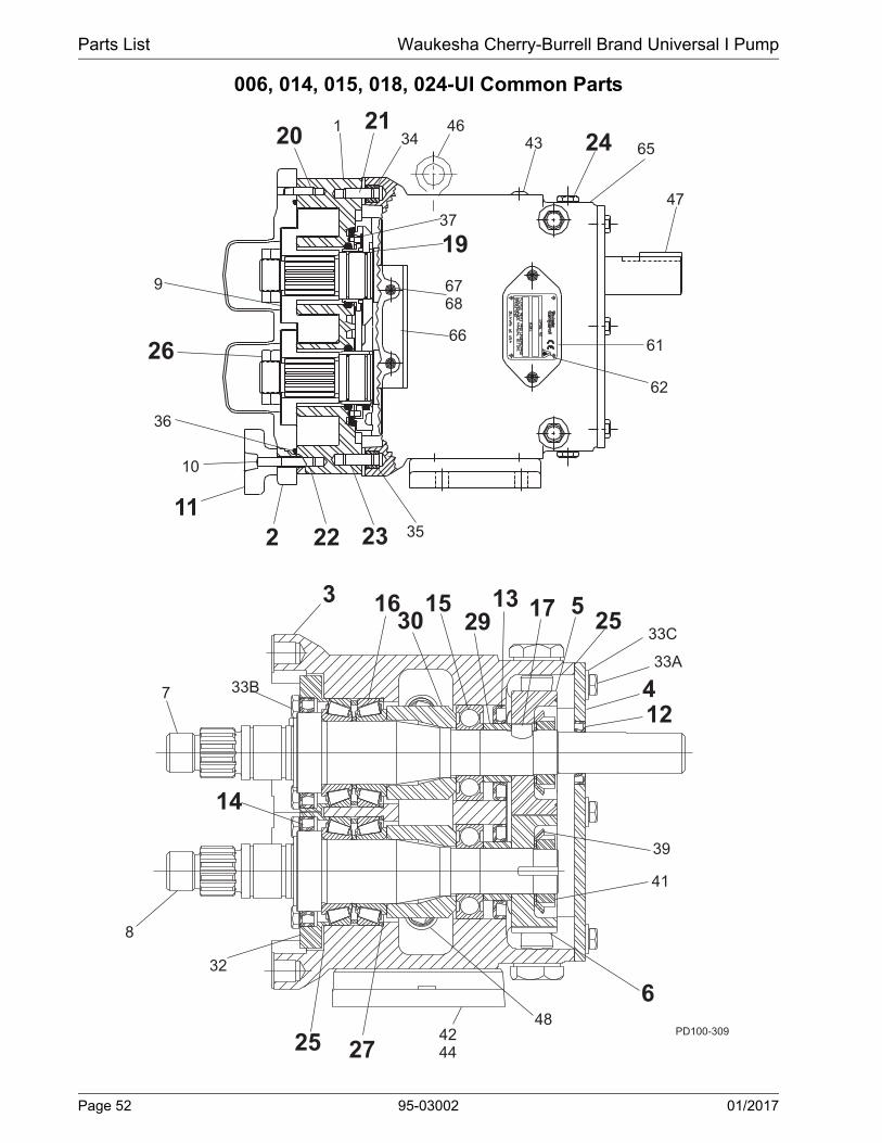
Parts List Waukesha Cherry-Burrell Brand Universal I Pump
006, 014, 015, 018, 024-UI Common Parts
43 24
47
61
62
6768
3523222
11
10
36
26
9
201 21
34
37
65
19
66
PD100-309
3 1630
1529
13 17 525 33C
33A
412
39
41
648
42442725
32
8
14
7 33B
46
Page 52 95-03002 01/2017
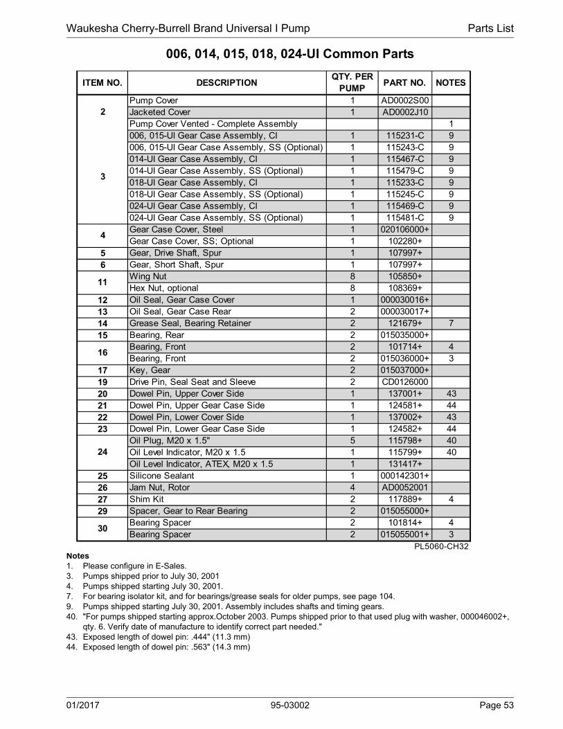
Waukesha Cherry-Burrell Brand Universal I Pump Parts List
006, 014, 015, 018, 024-UI Common Parts
Notes1. Please configure in E-Sales.3. Pumps shipped prior to July 30, 20014. Pumps shipped starting July 30, 2001.7. For bearing isolator kit, and for bearings/grease seals for older pumps, see page 104.9. Pumps shipped starting July 30, 2001. Assembly includes shafts and timing gears.40. "For pumps shipped starting approx.October 2003. Pumps shipped prior to that used plug with washer, 000046002+,
qty. 6. Verify date of manufacture to identify correct part needed."43. Exposed length of dowel pin: .444" (11.3 mm)44. Exposed length of dowel pin: .563" (14.3 mm)
ITEM NO. DESCRIPTIONQTY. PER
PUMPPART NO. NOTES
Pump Cover 1 AD0002S00Jacketed Cover 1 AD0002J10Pump Cover Vented - Complete Assembly 1006, 015-UI Gear Case Assembly, CI 1 115231-C 9006, 015-UI Gear Case Assembly, SS (Optional) 1 115243-C 9014-UI Gear Case Assembly, CI 1 115467-C 9014-UI Gear Case Assembly, SS (Optional) 1 115479-C 9018-UI Gear Case Assembly, CI 1 115233-C 9018-UI Gear Case Assembly, SS (Optional) 1 115245-C 9024-UI Gear Case Assembly, CI 1 115469-C 9024-UI Gear Case Assembly, SS (Optional) 1 115481-C 9Gear Case Cover, Steel 1 020106000+Gear Case Cover, SS; Optional 1 102280+
5 Gear, Drive Shaft, Spur 1 107997+6 Gear, Short Shaft, Spur 1 107997+
Wing Nut 8 105850+Hex Nut, optional 8 108369+
12 Oil Seal, Gear Case Cover 1 000030016+13 Oil Seal, Gear Case Rear 2 000030017+14 Grease Seal, Bearing Retainer 2 121679+ 715 Bearing, Rear 2 015035000+
Bearing, Front 2 101714+ 4Bearing, Front 2 015036000+ 3
17 Key, Gear 2 015037000+19 Drive Pin, Seal Seat and Sleeve 2 CD012600020 Dowel Pin, Upper Cover Side 1 137001+ 4321 Dowel Pin, Upper Gear Case Side 1 124581+ 4422 Dowel Pin, Lower Cover Side 1 137002+ 4323 Dowel Pin, Lower Gear Case Side 1 124582+ 44
Oil Plug, M20 x 1.5" 5 115798+ 40Oil Level Indicator, M20 x 1.5 1 115799+ 40Oil Level Indicator, ATEX, M20 x 1.5 1 131417+
25 Silicone Sealant 1 000142301+26 Jam Nut, Rotor 4 AD005200127 Shim Kit 2 117889+ 429 Spacer, Gear to Rear Bearing 2 015055000+
Bearing Spacer 2 101814+ 4Bearing Spacer 2 015055001+ 3
PL5060-CH32
3
30
24
2
4
11
16
01/2017 95-03002 Page 53

Parts List Waukesha Cherry-Burrell Brand Universal I Pump
006, 014, 015, 018, 024-UI Common Parts, cont’d
43 24
47
61
62
6768
3523222
11
10
36
26
9
201 21
34
37
65
19
66
PD100-310
3 1630
1529
13 17 525 33C
33A412
39
41
6
484244
2725
32
8
14
7 33B
46
Page 54 95-03002 01/2017

Waukesha Cherry-Burrell Brand Universal I Pump Parts List
006, 014, 015, 018, 024-UI Common Parts, cont’d
Notes: * Recommended Spare Parts1. Used with seal part # 121679+. See page 104.2. For SS gearcase or bearing isolator; used with seal part # 101716+. See page 104.7. For bearing isolator kit, and for bearings/grease seals for older pumps, see page 104.14. New O-Rings N70245 (024) introduced in 2001. Fits close to inlet opening. 15. For an older gearcase without a threaded plug hole, use plug p/n 000121003+.16. Decal kit contains 2 x 121694+ (Caution, Read Manual label); 2 x 33-63 (Small Warning label (models 006-040)); 2 x
33-60 (Large Warning label (models 060-320); 1 x 7403951 (SPX Name Label); 1 x 125115+ (Patent Label).
ITEM NO. DESCRIPTIONQTY. PER
PUMPPART NO. NOTES
Bearing Retainer, Front 2 120332+ 7, 1Bearing Retainer, Front (for SS Gearcase) 2 101810+ 7, 21/4-20 x .75" HHCS, Standard 14 30-2871/4-20 x .75" HHCS, SS 14 30-58
33C 1/4" Flat Washer, Gear Case Cover 6 43-10834 Dowel Bushing, Upper 1 AD011600035 Dowel Bushing, Lower 1 AD0116100
* O-Ring, Pump Cover, Buna N 1 N70252* O-Ring, Pump Cover, EPDM 1 E70252* O-Ring, Pump Cover, FKM 1 V70252* O-Ring, Pump Cover, Silicone 1 S75251* 014-UI O-Ring, Rectangular Flange 1 N70241* 024-UI O-Ring, Rectangular Flange 1 N70241 14* 024-UI O-Ring, Rectangular Flange 1 N70245 14
37 Stop Pin, Seal 2 015126000+39 Lockwasher, Gear 2 STD13600541 Locknut, Gear 2 STD236005
Gear Case Shim, CI 1 020110000+Gear Case Shim, SS; Optional 1 102284+Pump Pedestal, 6.75"; Optional 1 014110675+
43 Plastic Cap Plug 8 000121003+5/16-18 x 1" SHCS, Standard 4 30-3435/16-18 x 1" SHCS, SS 4 30-525006, 014, 015-UI Body Retaining Screw 2 30-523018, 024-UI Body Retaining Screw 2 30-704
46 Eye Bolt 2 30-72247 Key, Coupling - 3/16 x 3/16 x 1-1/8" 1 000037001+48 Cleanout Plug 2 35824+ 1561 Name Plate, Sanitary 1 126530+62 #2 x .125" RHDS 4 30-35565 Caution Plate 2 121694+66 Warning Label 2 33-63 16
006, 015, 018 - UI Grease Fitting, 1/8" (straight) 4 BD0092000014, 024-UI Grease Fitting, 1/8" (angled) 4 BD0092100
68 Plastic Cap, Grease Fitting 4 BD009300066 Warning Label 2 33-63 16
PL5060-CH33
32
67
44
33A, 33B
36
42
36B
45
01/2017 95-03002 Page 55

Parts List Waukesha Cherry-Burrell Brand Universal I Pump
030, 033A, 034, 040-UI Pump Parts
43 24
47
61
62
6768
3523222
11
10
36
26
9
201 21
34
37
4665
19
66
3 1630
1529
13 17 525 33C
33A
412
39
41
6
4842442725
32
8
14
7 33B
PD100-311
Page 56 95-03002 01/2017

Waukesha Cherry-Burrell Brand Universal I Pump Parts List
030, 033A, 034, 040-UI Pump Parts
Notes:1. Contact Factory with Serial Number of pump for Part Number.2. Standard clearances and finishes for Rotor Part Numbers shown. Contact Factory for optional clearances and finishes.3. Pumps shipped prior to July 30, 2001.4. Pumps shipped starting July 30, 2001. 5. No longer manufactured, consult factory for upgrade of gear case subassembly. 12. Replaces 030010010 straight and 030010090 90° (degree) rotors. 12A.Replaces 33A010010 straight and 33A010090 90° (degree) rotors. 13. Single wing rotors cannot be used in Rectangular Flange Inlet pumps.43. Tru-Fit drive shaft is longer than the standard drive shaft listed here. See page 102. 46. SPX FLOW now offers shafts with pressed-on bearings. See page 103.
ITEM NO.
DESCRIPTIONQTY. PER
PUMPPART NO. NOTES
030, 034, 040-UI Pump Body 1 SeeNote1 1033A-UI Pump Aseptic Body 1 033001020+030, 034-UI Drive Shaft, Std. 1 030008000+ 3, 43, 46030, 034-UI Drive Shaft, Optional 17-4PH 1 35341+ 3, 43, 46030, 034-UI Drive Shaft, Std. 1 114646+ 4, 43, 46030, 034-UI Drive Shaft, Optional 17-4PH 1 114779+ 4, 43, 46033A-UI Drive Shaft, Std. 1 033008000+ 3, 43, 46033A-UI Drive Shaft, Std. 1 114648+ 4, 43, 46040-UI Drive Shaft, Std. 1 118718+ 43, 46040-UI Drive Shaft, Optional 17-4PH 1 118812+ 43, 46030, 034-UI Short Shaft, Std. 1 030009000+ 3, 46030, 034-UI Short Shaft, Optional 17-4PH 1 35342+ 3, 46030, 034-UI Short Shaft, Std. 1 114647+ 4, 46030, 034-UI Short Shaft, Optional 17-4PH 1 114780+ 4, 46033A-UI Short Shaft, Std. 1 033009000+ 3, 46033A-UI Short Shaft, Std. 1 114649+ 4, 46040-UI Short Shaft, Std. 1 118719+ 46040-UI Short Shaft, Optional 17-4PH 1 118813+ 46030, 034-UI Rotor, Twin Wing, Alloy 88 2 030010000+ 2030, 034-UI Rotor, Twin Wing, 316SS 2 030010200+ 2030-UI Rotor, Single Wing, Alloy 88 2 117291+ 2, 12, 13033A-UI Rotor, Twin Wing, Alloy 88 2 33A010000 2033A-UI Rotor, Single Wing, Alloy 88 2 117326+ 2, 12A040-UI Rotor, Twin Wing, Alloy 88 2 118728+ 2040-UI Rotor, Twin Wing, 316SS 2 118753+ 2040-UI Rotor, Single Wing, Alloy 88 2 122711+ 2, 13
10A 030-033A-UI Stud 8 108842+10B 030-033A-UI Stud, Jacketed Cover 8 108845+
034-UI Stud 6 108842+034-UI Stud 2 35555+034-UI Stud, Jacketed Cover 6 108845+034-UI Stud, Jacketed Cover 2 35549+040-UI Stud 8 118897+040-UI Stud, Jacketed Cover 8 118898+Stud Retainer Assembly 1 Contact Factory 5
PL5060-CH36a
1
9
10E
10D
10C
7
8
01/2017 95-03002 Page 57

Parts List Waukesha Cherry-Burrell Brand Universal I Pump
43 24
47
61
62
6768
3523222
11
10
36
26
9
201 21
34
37
4665
19
66
3 1630 29
13 17 525
33C
33A412
39
41
648
42442725
32
8
14
7 33B
PD100-312
PD100-313
2
Aseptic Cover
030, 033A, 034, 040-UI Common Parts
Page 58 95-03002 01/2017

Waukesha Cherry-Burrell Brand Universal I Pump Parts List
030, 033A, 034, 040-UI Common Parts
Notes:1. Please configure in E-Sales.3. Pumps shipped prior to July 30, 2001. Verify the serial number of the pump to ensure the correct part is referenced.6. Gear case assy. includes timing gears and 316SS shafts. SS gearcase assy. includes 316LSS bearing retainer.7. For bearing isolator kit, and for bearings/grease seals for older pumps, see page 104.40. For pumps shipped after 5/15/03. Pumps shipped prior to 5/15/03 used plug w/washer, p/n 000046003+, qty. 6. Verify
date of manufacture to identify correct part needed.43. Exposed length of dowel pin: .444" (11.3 mm)44. Exposed length of dowel pin: .563" (14.3 mm)
ITEM NO.
DESCRIPTIONQTY. PER
PUMPPART NO.
NOTES
030, 034, 040-UI Pump Cover 1 BD0002S00030, 034, 040-UI Jacketed Cover 1 BD0002J10033A-UI Pump Cover 1 33A002020Pump Cover Vented - Complete Assembly 1030-UI Gear Case Assembly, CI 1 115235-C 6030-Gear Case Assembly, SS; Optional 1 115247-C 6033A-UI Gear Case Assembly, CI 1 115289-C 6033A-UI Gear Case Assembly, SS; Optional 1 134061-C 6034-UI Gear Case Assembly, CI 1 115471-C 6034-UI Gear Case Assembly, SS; Optional 1 115483-C 6040-UI Gear Case Assembly, CI 1 121660-C 6040-UI Gear Case Assembly, SS; Optional 1 124125-C 6Gear Case Cover, Steel 1 040106000+Gear Case Cover, SS; Optional 1 102281+
5 Gear, Drive Shaft, Spur 1 107999+6 Gear, Short Shaft, Spur 1 107999+
Wing Nut 8 105851+Hex Nut, optional 8 108370+
12 Oil Seal, Gear Case Cover 1 000030013+13 Oil Seal, Gear Case Rear 2 000030014+14 Grease Seal, Bearing Retainer 2 121680+ 715 Bearing, Rear 2 030035000+
Bearing, Front 2 101715+Bearing, Front 2 030036000+ 3
17 Key, Gear 2 BD003700019 Drive Pin, Seal Seat and Sleeve 2 CD012600020 Dowel Pin, Upper Cover Side 1 137001+ 4321 Dowel Pin, Upper Gear Case Side 1 124582+ 4422 Dowel Pin, Lower Cover Side 1 137002+ 4323 Dowel Pin, Lower Gear Case Side 1 124583+ 44
Oil Plug, M20 x 1.5" 5 115798+ 40Oil Level Indicator, M20 x 1.5 1 115799+ 40Oil Level Indicator, ATEX, M20 x 1.5 1 131417+
25 Silicone Sealant 1 000142301+26 Jam Nut, Rotor 4 BD005200127 Shim Kit 2 117890+29 Spacer, Gear to Rear Bearing 2 030055000+30 Bearing Spacer 2 101815+32 Bearing Retainer, Front 2 120333+ 7
PL5060-CH37a
24
2
3
4
11
16
01/2017 95-03002 Page 59

Parts List Waukesha Cherry-Burrell Brand Universal I Pump
030, 033A, 034, 040-UI Common Parts, cont’d
43 24
47
61
62
6768
3523222
11
10
36
26
9
201 21
34
37
4665
19
66
PD100-315
3 1630
1529
13 17 525 33C
33A412
3941
6
4842, 442725
32
8
14
7 33B
1
36
36A
PD100-320Aseptic Cover
58
60
57
59
Typical
Aseptic Port
PD100-306
Page 60 95-03002 01/2017
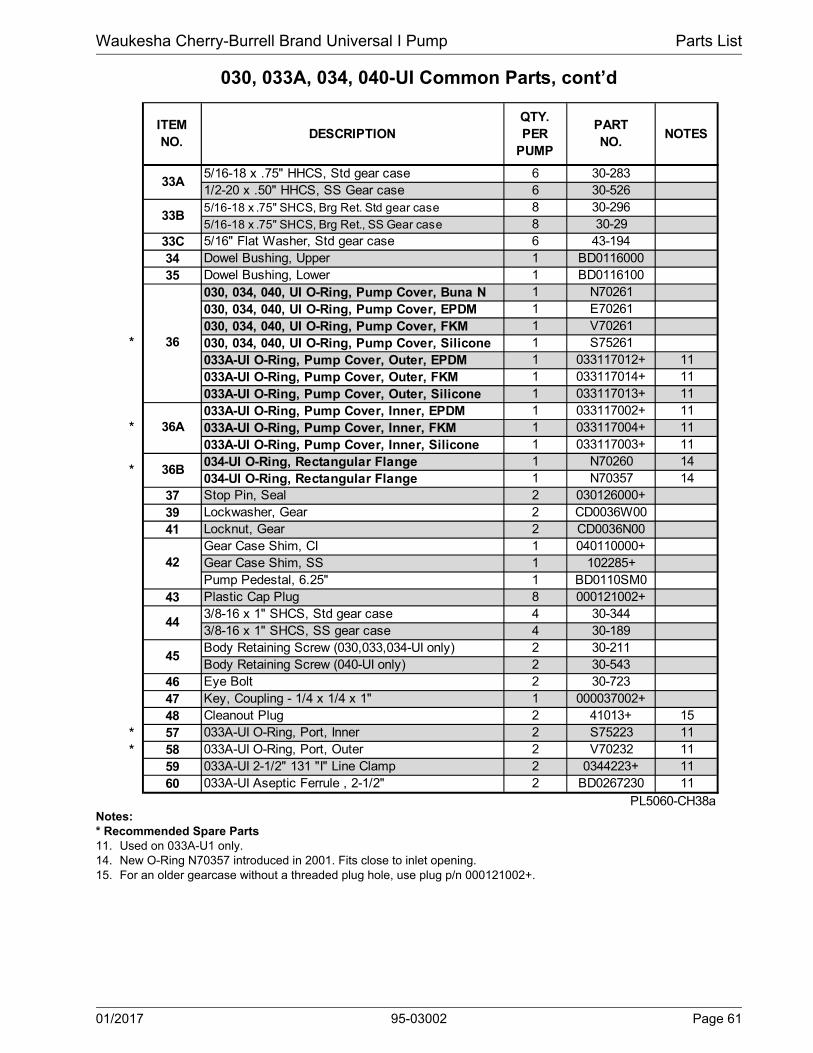
Waukesha Cherry-Burrell Brand Universal I Pump Parts List
030, 033A, 034, 040-UI Common Parts, cont’d
Notes:* Recommended Spare Parts11. Used on 033A-U1 only. 14. New O-Ring N70357 introduced in 2001. Fits close to inlet opening. 15. For an older gearcase without a threaded plug hole, use plug p/n 000121002+.
ITEM NO.
DESCRIPTIONQTY. PER
PUMP
PART NO.
NOTES
5/16-18 x .75" HHCS, Std gear case 6 30-2831/2-20 x .50" HHCS, SS Gear case 6 30-5265/16-18 x .75" SHCS, Brg Ret. Std gear case 8 30-2965/16-18 x .75" SHCS, Brg Ret., SS Gear case 8 30-29
33C 5/16" Flat Washer, Std gear case 6 43-19434 Dowel Bushing, Upper 1 BD011600035 Dowel Bushing, Lower 1 BD0116100
030, 034, 040, UI O-Ring, Pump Cover, Buna N 1 N70261030, 034, 040, UI O-Ring, Pump Cover, EPDM 1 E70261030, 034, 040, UI O-Ring, Pump Cover, FKM 1 V70261030, 034, 040, UI O-Ring, Pump Cover, Silicone 1 S75261033A-UI O-Ring, Pump Cover, Outer, EPDM 1 033117012+ 11033A-UI O-Ring, Pump Cover, Outer, FKM 1 033117014+ 11033A-UI O-Ring, Pump Cover, Outer, Silicone 1 033117013+ 11033A-UI O-Ring, Pump Cover, Inner, EPDM 1 033117002+ 11033A-UI O-Ring, Pump Cover, Inner, FKM 1 033117004+ 11033A-UI O-Ring, Pump Cover, Inner, Silicone 1 033117003+ 11034-UI O-Ring, Rectangular Flange 1 N70260 14034-UI O-Ring, Rectangular Flange 1 N70357 14
37 Stop Pin, Seal 2 030126000+39 Lockwasher, Gear 2 CD0036W0041 Locknut, Gear 2 CD0036N00
Gear Case Shim, CI 1 040110000+Gear Case Shim, SS 1 102285+Pump Pedestal, 6.25" 1 BD0110SM0
43 Plastic Cap Plug 8 000121002+3/8-16 x 1" SHCS, Std gear case 4 30-3443/8-16 x 1" SHCS, SS gear case 4 30-189Body Retaining Screw (030,033,034-UI only) 2 30-211Body Retaining Screw (040-UI only) 2 30-543
46 Eye Bolt 2 30-72347 Key, Coupling - 1/4 x 1/4 x 1" 1 000037002+48 Cleanout Plug 2 41013+ 15
* 57 033A-UI O-Ring, Port, Inner 2 S75223 11* 58 033A-UI O-Ring, Port, Outer 2 V70232 11
59 033A-UI 2-1/2" 131 "I" Line Clamp 2 0344223+ 1160 033A-UI Aseptic Ferrule , 2-1/2" 2 BD0267230 11
PL5060-CH38a
36A
45
*
*
*
33A
33B
36
42
44
36B
01/2017 95-03002 Page 61

Parts List Waukesha Cherry-Burrell Brand Universal I Pump
030, 033A, 034, 040-UI Common Parts, cont’d
43 24
47
61
62
6768
3523222
11
10
36
26
9
201 21
34
37
65
19
66
PD100-316
Page 62 95-03002 01/2017
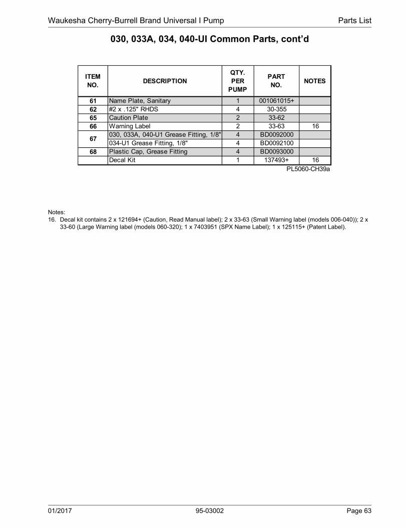
Waukesha Cherry-Burrell Brand Universal I Pump Parts List
030, 033A, 034, 040-UI Common Parts, cont’d
Notes:16. Decal kit contains 2 x 121694+ (Caution, Read Manual label); 2 x 33-63 (Small Warning label (models 006-040)); 2 x
33-60 (Large Warning label (models 060-320); 1 x 7403951 (SPX Name Label); 1 x 125115+ (Patent Label).
ITEM NO.
DESCRIPTIONQTY. PER
PUMP
PART NO.
NOTES
61 Name Plate, Sanitary 1 001061015+62 #2 x .125" RHDS 4 30-35565 Caution Plate 2 33-6266 Warning Label 2 33-63 16
030, 033A, 040-U1 Grease Fitting, 1/8" 4 BD0092000034-U1 Grease Fitting, 1/8" 4 BD0092100
68 Plastic Cap, Grease Fitting 4 BD0093000Decal Kit 1 137493+ 16
PL5060-CH39a
67
01/2017 95-03002 Page 63

Parts List Waukesha Cherry-Burrell Brand Universal I Pump
060, 064, 130, 134, 133A-UI Pump Parts
43 24
47
61
62
6768
3523222
11
10
36
26
9
201 21
34
37
4665
19
66
3 1630
1529
13 17 525 33C
33A
412
39
41
6
482725
32
8
14
7 33B
PD100-317
1
36B
4244
Page 64 95-03002 01/2017

Waukesha Cherry-Burrell Brand Universal I Pump Parts List
060, 064, 130, 134, 133A-UI Pump Parts
Notes:1. Contact Factory with Serial Number of pump for Part Number.2. Standard clearances and finishes for Rotor Part Numbers shown.
Contact Factory for optional clearances and finishes.4. Pumps shipped starting approx. 1988. Pumps sold before 1988 also need bearing spacer 060055003+ (item 30) if they
have never made a change to the orig. pump. 5. No longer manufactured, consult factory for upgrade of gear case subassembly. 12. Replaces 060010010 straight and 060010090 90° (degree) rotors. 12A.Replaces 130010010 straight and 130010090 90° (degree) rotors. 12B.Replaces 133010010 straight and 133010090 90° (degree) rotors. 13. Single wing rotors cannot be used in Rectangular Flange Inlet pumps. 43. Tru-Fit drive shaft is longer than the standard drive shaft listed here. See page 102.46. SPX FLOW now offers shafts with pressed-on bearings. See page 103.
DESCRIPTIONQTY. PER
PUMPPART NO.
NOTES
060, 064, 130, 133A, 134-UI Pump Body 1 See Note 1 1060, 064-UI Drive Shaft 1 060008001+ 4, 43, 46060, 064-UI Drive Shaft, Optional 17-4PH 1 35145+ 43, 46130, 134-UI Drive Shaft 1 130008001+ 4, 43, 46130, 134-UI Drive Shaft, Optional 17-4PH 1 35394+ 43, 46133A-UI Drive Shaft 1 133008001+ 4, 43133A-UI Drive Shaft, Optional 17-4PH 1 34470+ 43, 46060, 064-UI Short Shaft 1 060009001+ 4, 46060, 064-UI Short Shaft, Optional 17-4PH 1 35146+ 43, 46130, 134-UI Short Shaft 1 130009001+ 4, 46130, 134-UI Short Shaft, Optional 17-4PH 1 35392+ 43, 46133A-UI Short Shaft 1 133009001+ 4133A-UI Short Shaft, Optional 17-4PH 1 34471+060, 064-UI Rotor, Twin Wing, Alloy 88 2 060010000+ 2060, 064-UI Rotor, Twin Wing, 316SS 2 060010200+ 2060-UI Rotor, Single Wing, Alloy 88 2 117343+ 2, 12, 13130, 134-UI Rotor, Twin Wing, Alloy 88 2 130010000+ 2130, 134-UI Rotor, Twin Wing, 316SS 2 130010200+ 2130-UI Rotor, Single Wing, Alloy 88 2 117360+ 2, 12A, 13133A-UI Rotor, Twin Wing, Alloy 88 2 133010020+ 2133A-UI Rotor, Single Wing, Alloy 88 2 117377+ 2, 12B060-UI Stud 8 108843+060-UI Stud, Jacketed Cover 8 108846+060-UI Stud Retainer Assembly 1 070064000+ 5064-UI Stud 6 108843+064-UI Stud 2 0C1050000064-UI Stud, Jacketed Cover 6 108846+064-UI Stud, Jacketed Cover 2 35556+130, 133A-UI Stud 8 130011000+130-UI Stud, Jacketed Cover 8 130011001+130, 133A-UI Stud Retainer Assembly 1 140064000+ 5134-UI Stud 6 130011000+134-UI Stud 2 0C1050000134-UI Stud, Jacketed Cover 6 130011001+134-UI Stud, Jacketed Cover 2 35556+
PL5060-CH48
ITEM NO.
10H
9
10D
10E
10I
10J
10F10G
10B10C
10A
1
7
8
01/2017 95-03002 Page 65

Parts List Waukesha Cherry-Burrell Brand Universal I Pump
060, 064, 130, 134, 133A-UI Common Parts
43 24
47
61
62
6768
3523222
11
10
36
26
9
201 21
34
37
4665
19
66
3 1630 29
13 17 525
33C
33A412
39
41
648
25
32
8
14
7 33B
PD100-313
2
Aseptic Cover
31
PD100-31915
4244
Page 66 95-03002 01/2017
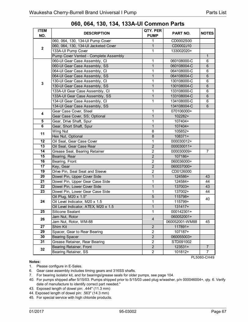
Waukesha Cherry-Burrell Brand Universal I Pump Parts List
060, 064, 130, 134, 133A-UI Common Parts
Notes:1. Please configure in E-Sales.6. Gear case assembly includes timing gears and 316SS shafts.7. For bearing isolator kit, and for bearings/grease seals for older pumps, see page 104.40. For pumps shipped after 5/15/03. Pumps shipped prior to 5/15/03 used plug w/washer, p/n 000046004+, qty. 6. Verify
date of manufacture to identify correct part needed."43. Exposed length of dowel pin: .444" (11.3 mm) 44. Exposed length of dowel pin: .563" (14.3 mm)45. For special service with high chloride products.
DESCRIPTIONQTY. PER
PUMPPART NO. NOTES
060, 064, 130, 134-UI Pump Cover 1 CD0002S00060, 064, 130, 134-UI Jacketed Cover 1 CD0002J10133A-UI Pump Cover 1 133002020+Pump Cover Vented - Complete Assembly 1060-UI Gear Case Assembly, CI 1 060108000-C 6060-UI Gear Case Assembly, SS 1 060108004-C 6064-UI Gear Case Assembly, CI 1 064108000-C 6064-UI Gear Case Assembly, SS 1 064108004-C 6130-UI Gear Case Assembly, CI 1 130108000-C 6130-UI Gear Case Assembly, SS 1 130108004-C 6133A-UI Gear Case Assembly, CI 1 133108000-C 6133A-UI Gear Case Assembly, SS 1 133108004-C 6134-UI Gear Case Assembly, CI 1 134108000-C 6134-UI Gear Case Assembly, SS 134108004-C 6Gear Case Cover, Steel 1 070106000+Gear Case Cover, SS; Optional 1 102282+Gear, Drive Shaft, Spur 1 107404+Gear, Short Shaft, Spur 1 107404+Wing Nut 8 105852+Hex Nut, Optional 8 108371+Oil Seal, Gear Case Cover 1 000030012+Oil Seal, Gear Case Rear 2 000030011+Grease Seal, Bearing Retainer 2 000030009+ 7Bearing, Rear 2 107186+Bearing, Front 2 060036000+Key, Gear 2 060037000+Drive Pin, Seal Seat and Sleeve 2 CD0126000Dowel Pin, Upper Cover Side 1 124586+ 43Dowel Pin, Upper Gear Case Side 1 124584+ 44Dowel Pin, Lower Cover Side 1 137003+ 43Dowel Pin, Lower Gear Case Side 1 137002+ 44Oil Plug, M20 x 1.5" 5 115798+Oil Level Indicator, M20 x 1.5 1 115799+Oil Level Indicator, ATEX, M20 x 1.5 1 131417+Silicone Sealant 1 000142301+Jam Nut, Rotor 060052001+Jam Nut, Rotor, WM-88 060052001-WM88 45Shim Kit 2 117891+Spacer, Gear to Rear Bearing 2 107187+Bearing Spacer 2 060055003+Grease Retainer, Rear Bearing 2 STD091002Bearing Retainer, Front 2 123531+ 7Bearing Retainer, SS 2 101812+ 7
PL5060-CH49
40
151617
29
26
6
1213
ITEM NO.
4
32
3031
202122
24
2
3
4
11
14
27
25
23
5
19
01/2017 95-03002 Page 67

Parts List Waukesha Cherry-Burrell Brand Universal I Pump
060, 064, 130, 134, 133A-UI Common Parts, cont’d
58
60
57
59
Typical
Aseptic Port
PD100-306
43 24
47
61
62
6768
3523222
11
10
36
26
9
201 21
34
37
46
65
19
66
PD100-321a
3 1630
1529
13 17 525 33C
33A412
3941
6
484244
2725
32
8
14
7 33B
1
36B
1
36
36A
PD100-320Aseptic Cover
Page 68 95-03002 01/2017

Waukesha Cherry-Burrell Brand Universal I Pump Parts List
060, 064, 130, 134, 133A-UI Common Parts, cont’d
Notes:* Recommended Spare Parts11. Used on 133A-U1 only. 14. New O-Rings N70366 (064) and N70369 (134) introduced in 2001. Fits close to inlet opening.
ITEM NO.
DESCRIPTIONQTY. PER
PUMPPART NO.
NOTES
3/8-16 x .75" HHCS, STD Gear Case Cover 6 30-3143/8-16 x .75" HHCS, SS Gear Case 6 30-503/8-16 x 1.25" HHCS, Brg. Ret., Std. Gear Case 8 30-3513/8-16 x 1.25" HHCS, Brg. Ret. SS Gear Case 8 30-60
33C 3/8" Flat Washer 6 43-18934 Dowel Bushing, Upper 1 CD011600035 Dowel Bushing, Lower 1 CD0116100
O-Ring, Pump Cover, Buna N 1 N70272O-Ring, Pump Cover, EPDM 1 E70272O-Ring, Pump Cover, FKM 1 V70272
O-Ring, Pump Cover, Silicone 1 S75272
133A-UI O-Ring Cord, EPDM 1 133117012+ 11
133A-UI O-Ring Cord, FKM 1 133117014+ 11
133A-UI O-Ring Cord, Silicone 1 133117013+ 11
133A-UI O-Ring, Pump Cover, Inner, EPDM 1 133117002+ 11
133A-UI O-Ring, Pump Cover, Inner, FKM 1 133117004+ 11
133A-UI O-Ring, Pump Cover, Inner, Silicone 1 133117003+ 11
064-UI O-Ring, Rectangular Flange, Buna N 1 35360+ 14
064-UI O-Ring, Rectangular Flange, Buna N 1 N70366 14
134-UI O-Ring, Rectangular Flange, Buna N 1 N70272 14
134-UI O-Ring, Rectangular Flange, Buna N 1 N70369 1437 Stop Pin, Seal 2 223126000+39 Lockwasher, Gear 2 STD13600941 Locknut, Gear 2 STD236009
Gear Case Shim, CI 1 070110000+Gear Case Shim, SS; Optional 1 102286+Pump Pedestal, 5.5", Optional 1 CD0110SM5Pump Pedestal, 10", Optional 1 CD0110SM1
43 Plastic Cap Plug 6 000121001+44 5/16-18 x 1" SHCS 4 30-275
060-064-UI Body Retaining Screw 2 30-319130-133A-134-UI Body Retaining Screw 2 30-423
46 Eye Bolt 2 30-36047 Key, Coupling - 3/8 x 3/8 x 1-5/8" 1 000037003+
PL5060-CH50
42
36A
36B
45
*
*
36*
33A
33B
01/2017 95-03002 Page 69

Parts List Waukesha Cherry-Burrell Brand Universal I Pump
060, 064, 130, 134, 133A-UI Common Parts, cont’d
58
60
57
59
Typical
Aseptic Port
PD100-306
43 24
47
61
62
6768
3523222
11
10
36
26
9
201 21
34
37
46
65
19
66
PD100-321a
3 1630
1529
13 17 525 33C
33A412
3941
6
484244
2725
32
8
14
7 33B
1
36B
1
36
36A
PD100-320Aseptic Cover
Page 70 95-03002 01/2017

Waukesha Cherry-Burrell Brand Universal I Pump Parts List
060, 064, 130, 134, 133A-UI Common Parts, cont’d
Notes:* Recommended Spare Parts11. Used on 133A-U1 only. 14. New O-Rings N70366 (064) and N70369 (134) introduced in 2001. Fits close to inlet opening.15. For an older gearcase without a threaded plug hole, use plug p/n 000121001+16. Decal kit contains 2 x 121694+ (Caution, Read Manual label); 2 x 33-63 (Small Warning label (models 006-040)); 2 x
33-60 (Large Warning label (models 060-320); 1 x 7403951 (SPX Name Label); 1 x 125115+ (Patent Label).
ITEM NO.
DESCRIPTIONQTY. PER
PUMPPART NO.
NOTES
48 Cleanout Plug 2 41013+ 15133A-UI O-Ring, Port, Inner, Silicone 2 S75041 11133A-UI O-Ring, Port, Inner, EPDM 2 E70041 11133A-UI O-Ring, Port, Outer, Silicone 2 S75043 11133A-UI O-Ring, Port, Outer, EPDM 2 E70043 11
* 59 133A-UI 3" 13I "I" Line Clamp 2 0345223+ 11* 60 133A-UI Aseptic Ferrule, 3" 2 133267000+ 11
61 Name Plate, Sanitary 1 001061015+62 #2 x .125" RHDS 4 30-35565 Caution Plate 2 121694+66 Warning Label 2 33-60 16
060, 130, 133A-UI Grease Fitting, 1/8" (straight) 4 BD0092000064-134-UI Grease Fitting, 1/8" (angled) 4 BD0092100
68 Plastic Cap, Grease Fitting 4 BD0093000Decal Kit 1 137493+ 16
PL5060-CH50a
*
*
67
58
57
01/2017 95-03002 Page 71

Parts List Waukesha Cherry-Burrell Brand Universal I Pump
220, 223A, 224-UI Pump Parts
43 24
47
61
62
6768
3523222
11
10
36
26
9
201 21
34
37
4665
19
66
3 1630
1529
13 17 525 33C
33A
412
39
41
6
482725
32
8
14
7 33B
PD100-317
1
36B
4244
Page 72 95-03002 01/2017

Waukesha Cherry-Burrell Brand Universal I Pump Parts List
220, 223A, 224-UI Pump Parts
Notes:1. Contact Factory with Serial Number of pump for Part Number. 2. Standard clearance and finish Part Number shown. Contact Factory for optional clearances and finishes.4. Pumps shipped starting approx. 1988. Pumps sold before 1988 also need bearing spacer 40752+ (item 30) if they
have never made a change to the orig. pump. 5. No longer manufactured, consult factory for upgrade of gear case subassembly. 12. Replaces 220010010 straight and 220010090 90° rotors.13. Single wing rotors cannot be used in Rectangular Flange Inlet pumps. 43. Tru-Fit drive shaft is longer than the standard drive shaft listed here. See page 102. 46. SPX FLOW now offers shafts with pressed-on bearings. See page 103.
DESCRIPTIONQTY. PER
PUMPPART NO.
NOTES
220-UI Pump Body 1 See Note 1 1220-UI Pump Body with Flush 1 See Note 1 1224-UI Rectangular Flange Inlet Body 1 See Note 1 1224-UI Rect. Flange Inlet Body with Flush 1 See Note 1 1223A-UI Pump Body 1 223001020+220, 224-UI Drive Shaft, Std. 1 220008001+ 4, 46220, 224-UI Drive Shaft, Optional 17-4PH 1 35349+ 46223A-UI Drive Shaft 1 223008001+ 4, 46223A-UI Drive Shaft, Optional 17-4PH 1 35726+ 46220, 224-UI Short Shaft, Std. 1 220009001+ 4, 46220, 224-UI Short Shaft, Optional 17-4PH 1 35350+ 46223A-UI Short Shaft 1 223009001+ 4, 46223A-UI Short Shaft, Optional 17-4PH 1 35727+ 46220, 224-UI Rotor, Twin Wing, Alloy 88 2 220010000+ 2220, 224-UI Rotor, Twin Wing, 316SS 2 220010200+ 2220, 224-UI Rotor, Single Wing, Alloy 88 2 117391+ 2, 12, 13223A-UI Rotor, Twin Wing, Alloy 88 2 223010020+ 2220-UI Stud 8 108844+220-UI Stud, Jacketed Cover 8 108847+224-UI Stud 6 108844+224-UI Stud 2 35550+224-UI Stud, Jacketed Cover 6 108847+224-UI Stud, Jacketed Cover 2 36144+Stud Retainer Assembly 1 230064000+ 5
PL5060-CH53
7
ITEM NO.
1
10A10B
10C
10D
8
9
01/2017 95-03002 Page 73

Parts List Waukesha Cherry-Burrell Brand Universal I Pump
220, 223A, 224-UI Common Parts
43 24
47
61
62
6768
3523222
11
10
36
26
9
201 21
34
37
4665
19
66
3 1630 29
13 17 525
33C
33A
412
39
41
648
4244
2725
32
8
14
7 33B
PD100-322a
PD100-313
2
Aseptic Cover
31
15PD100-319
Page 74 95-03002 01/2017

Waukesha Cherry-Burrell Brand Universal I Pump Parts List
220, 223A, 224-UI Common Parts
Notes:1. Please configure in E-Sales.7. For bearing isolator kit, and for bearings/grease seals for older pumps, see page 104.8. Used in pumps manufactured after approx. 06/1993.40. Pumps shipped prior to 5/15/03 used plug w/washer, p/n 000046004+, qty. 6. Verify date of manufacture.42. For pumps shipped prior to 5/15/03: Consult factory and provide serial number for upgrade of gear case assembly.43. Exposed length of dowel pin: .444" (11.3 mm)44. Exposed length of dowel pin: .563" (14.3 mm)
ITEM NO.
DESCRIPTIONQTY. PER
PUMPPART NO.
NOTES
220, 224-UI Pump Cover 1 GD0002S00220, 224-UI Jacketed Cover 1 GD0002J10223A-UI Pump Cover 1 223002020+Pump Cover Vented - Complete Assembly 1220-UI Gear Case Assembly, CI 1 220108000-C 42220-UI Gear Case Assembly, SS; Optional 1 220108004-C 42223A-UI Gear Case Assembly, Cl 1 223108000-C 42223A-UI Gear Case Assembly, SS; Optional 1 223108004-C 42224-UI Gear Case Assembly, Cl 1 224108000-C 42224-UI Gear Case Assembly, SS; Optional 1 224108004-C 42Gear Case Cover, Steel 1 230106000+Gear Case Cover, SS; Optional 1 102283+
5 Gear, Drive Shaft, Spur 1 110932+6 Gear, Short Shaft, Spur 1 110932+
Wing Nut 8 105853+Hex Nut, optional 8 108372+
12 Oil Seal, Gear Case Cover 1 STD03000613 Oil Seal, Gear Case Rear 2 STD11900214 Grease Seal, Bearing Retainer 2 121681+ 715 Bearing, Rear 2 200035000+16 Bearing, Front 2 200036000+17 Key, Gear 2 200037000+19 Drive Pin, Seal Seat and Sleeve 2 CD012600020 Dowel Pin, Upper Cover Side 1 124586+ 4321 Dowel Pin, Upper Gear Case Side 1 124584+ 4422 Dowel Pin, Lower Cover Side 1 137005+ 4323 Dowel Pin, Lower Gear Case Side 1 137004+ 44
Oil Plug, M20 x 1.5" 5 115798+ 40Oil Level Indicator, M20 x 1.5" 1 115799+
25 Silicone Sealant 1 000142301+26 Jam Nut, Rotor 4 GD005200127 Shim Kit 2 117892+29 Spacer, Gear to Rear Bearing 2 40878+30 Bearing Spacer 2 40752+31 Grease Retainer, Rear Bearing 2 STD091001
PL5060-CH54
24
3
2
4
11
01/2017 95-03002 Page 75

Parts List Waukesha Cherry-Burrell Brand Universal I Pump
220, 223A, 224-UI Common Parts, cont’d
58
60
57
59
Typical Aseptic Port
PD100-306
43 24
61
62
6768
3523222
11
10
36
26
9
201 21
34
37
4665
19
66
PD100-323a
3 1630
1529
13 17 525 33C
33A412
3941
6
48
4244
2725
32
8
14
7 33B
1
36
36A
PD100-320
Aseptic Cover
1
36B
47
Page 76 95-03002 01/2017

Waukesha Cherry-Burrell Brand Universal I Pump Parts List
220, 223A, 224-UI Common Parts, cont’d
Notes:* Recommended Spare Parts7. For bearing isolator kit, and for bearings/grease seals for older pumps, see page 104.11. Used on 223A-UI only. 12. New O-Ring N70376 introduced in 2001. Fits close to inlet opening.15. For an older gearcase without a threaded plug hole, use plug p/n 000121001+
ITEM NO.
DESCRIPTIONQTY. PER
PUMPPART NO.
NOTES
Bearing Retainer, Front; STD. 2 123532+ 7Bearing Retainer, Front; SS 2 101813+ 73/8-16 x .75" HHCS, Std gear case 6 30-3143/8-16 x .75" HHCS, SS Gear case 6 30-503/8-16 x 1.25" SHCS, Brg Ret. Std gear case 8 30-3513/8-16 x 1.25" SHCS, Brg Ret., SS Gear case 8 30-60
33C 3/8" Flat Washer, Std gear case 6 43-18934 Dowel Bushing, Upper 1 CD011600035 Dowel Bushing, Lower 1 CD0116100
* O-Ring, Pump Cover, Buna N 1 GD0117000* O-Ring, Pump Cover, EPDM 1 GD0117002* O-Ring, Pump Cover, FKM 1 GD0117V00* O-Ring, Pump Cover, Silicone 1 GD0117SC0* 223A-UI O-Ring, Pump Cover, Inner, EPDM 1 223117002+ 11* 223A-UI O-Ring, Pump Cover, Inner, FKM 1 V70278 11* 223A-UI O-Ring, Pump Cover, Inner, Silicone 1 223117003+ 11
224-UI O-Ring, Rectangular Flange 1 GD0117000 12224-UI O-Ring, Rectangular Flange 1 N70376 12
37 Stop Pin, Seal 2 223126000+39 Lockwasher, Gear 2 STD13601141 Locknut, Gear 2 STD236011
Gear Case Shim, CI 1 230110000+Gear Case Shim, SS 1 102287+Pump Pedestal, 9" 1 GD0110SM9Pump Pedestal, 13" 1 GD0110SM1
43 Plastic Cap Plug 8 000121001+1/2-13 x 2" SHCS, Std gear case 4 30-1111/2-13 x 2" SHCS, SS gear case 4 30-44
45 Body Retaining Screw 2 30-49946 1/2-13 Eye Bolt 2 30-36047 Key, Coupling - 1/2 x 1/2 x 1" 1 000037004+48 Cleanout Plug 2 41013+ 15
* 57 223A-UI O-Ring, Port, Inner 2 E70154 11* 58 223A-UI O-Ring, Port, Outer 2 E70158 11* 59 223A-UI 4" 13MHHMV "S" Clamp 2 119-87* 60 223A-UI Aseptic Ferrule, 4" 2 GGA267000
PL5060-CH55
32
42
44
33B
33A
36B
36A
36
01/2017 95-03002 Page 77
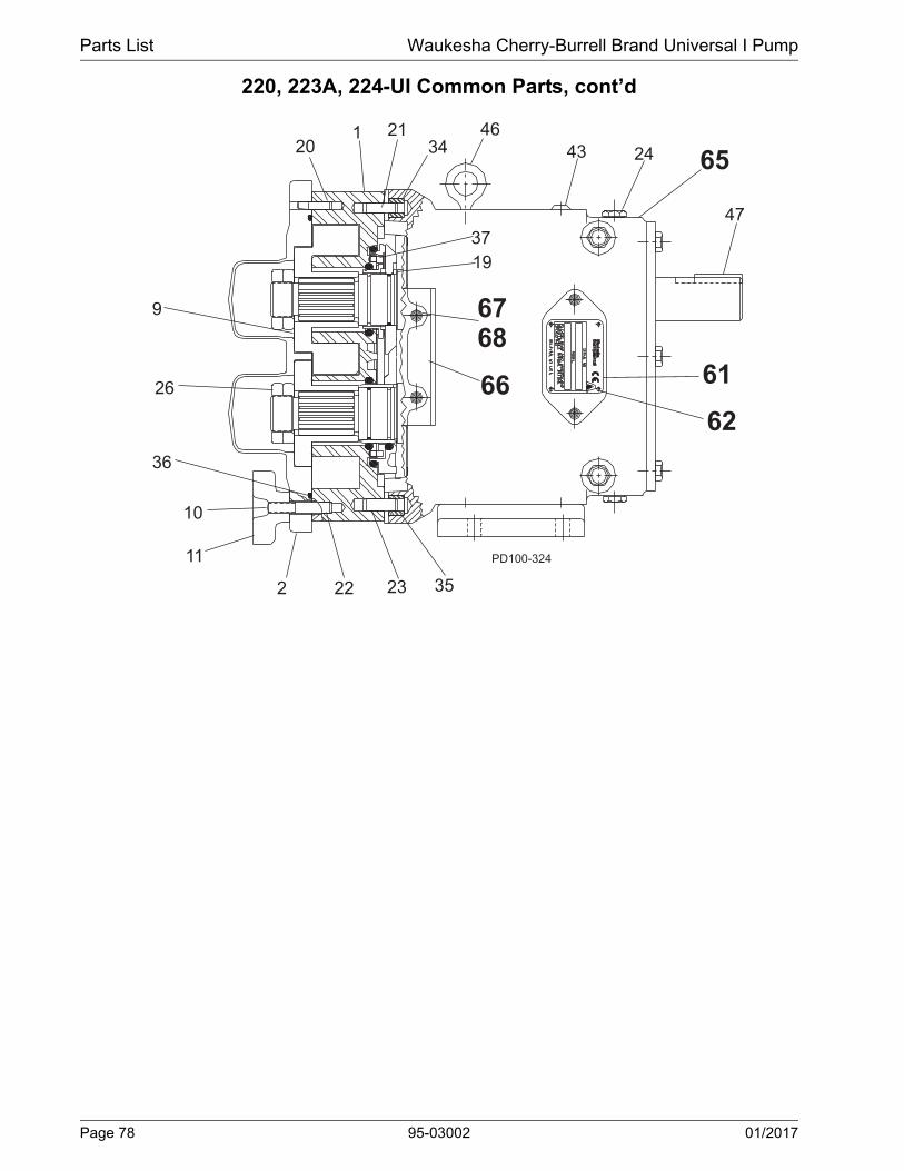
Parts List Waukesha Cherry-Burrell Brand Universal I Pump
220, 223A, 224-UI Common Parts, cont’d
43 24
47
61
62
6768
3523222
11
10
36
26
9
201 21
34
37
46
65
19
66
PD100-324
Page 78 95-03002 01/2017

Waukesha Cherry-Burrell Brand Universal I Pump Parts List
220, 223A, 224-UI Common Parts, cont’d
Notes:16. Decal kit contains 2 x 121694+ (Caution, Read Manual label); 2 x 33-63 (Small Warning label (models 006-040)); 2 x
33-60 (Large Warning label (models 060-320); 1 x 7403951 (SPX Name Label); 1 x 125115+ (Patent Label).
ITEM NO.
DESCRIPTIONQTY. PER
PUMP
PART NO.
NOTES
61 Name Plate, Sanitary 1 001061015+62 #2 x .125" RHDS 4 30-35565 Caution Plate 2 33-6266 Warning Label 2 33-60 16
220-223A-U1 Grease Fitting, 1/8" 4 BD0092000224-U1 Grease Fitting, 1/8" 4 BD0092100
68 Plastic Cap, Grease Fitting 4 BD0093000Decal Kit 1 137493+ 16
PL5060-CH56
67
01/2017 95-03002 Page 79
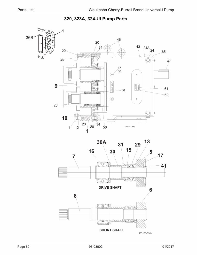
Parts List Waukesha Cherry-Burrell Brand Universal I Pump
320, 323A, 324-UI Pump Parts
PD100-331a
716
30A
30
3115
2913
175
41
68
DRIVE SHAFT
SHORT SHAFT
OUT OF PORTSKEEP FINGERSW
AR
NIN
G
MODEL
SERIAL NO.
OP
ER
ATING
.M
AIN
TEN
AN
CE
MA
NU
AL B
EFO
RE
PLE
AS
E R
EA
D A
ND
UN
DE
RS
TAN
D
DELAVAN, WI. U.S.A
2034
46
43 24A24 65
47
61
62
6768
66
5634
201
20211
10
26
9
36
20
PD100-332
1
36B
Page 80 95-03002 01/2017
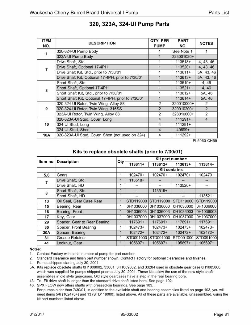
Waukesha Cherry-Burrell Brand Universal I Pump Parts List
320, 323A, 324-UI Pump Parts
Notes:1. Contact Factory with serial number of pump for part number. 2. Standard clearance and finish part number shown. Contact Factory for optional clearances and finishes. 4. Pumps shipped starting July 30, 2001. 5A. Kits replace obsolete shafts 0H1008002, 33081, 0H1009002, and 33204 used in obsolete gear case 0H1005000,
which was supplied for pumps shipped prior to July 30, 2001. These kits allow the use of the new style shaft assemblies in old style gearcases. Old style gearcases have a step in the rear bearing bore.
43. Tru-Fit drive shaft is longer than the standard drive shaft listed here. See page 102.46. SPX FLOW now offers shafts with pressed-on bearings. See page 103.
For pumps older than 7/30/01, in addition to the available shaft and bearing assemblies listed on page 103, you will need items 5/6 (102470+) and 13 (STD119000), listed above. All of these parts are available, unassembled, using the kit part numbers listed above.
ITEM NO.
QTY. PER PUMP
PART NO.
NOTES
1 See Note 1 11 323001020+1 113518+ 4, 43, 461 113520+ 4, 43, 461 113611+ 5A, 43, 461 113613+ 5A, 43, 461 113519+ 4, 461 113521+ 4, 461 113612+ 5A, 461 113614+ 5A, 462 320010000+ 22 320010200+ 22 323010000+ 24 111291+ 44 111291+4 40699+
10A 4 111292+
PL5060-CH59
113611+ 113612+ 113613+ 113614+
5,6 Gears 1 102470+ 102470+ 102470+ 102470+Drive Shaft, Std. 1 113518+ -- -- --Drive Shaft, HD 1 -- -- 113520+ --Short Shaft, Std. 1 -- 113519+ -- --Short Shaft, HD 1 -- -- -- 113521+
13 Oil Seal, Gear Case Rear 1 STD119000 STD119000 STD119000 STD11900015 Bearing, Rear 1 0H1036000 0H1036000 0H1036000 0H103600016 Bearing, Front 1 0H1036003 0H1036003 0H1036003 0H103600317 Key, Gear 1 0H1037000 0H1037000 0H1037000 0H103700029 Spacer, Gear to Rear Bearing 1 117691+ 117691+ 117691+ 117691+30 Spacer, Front Bearing 1 102473+ 102473+ 102473+ 102473+
30A Spacer, Bearing 1 102472+ 102472+ 102472+ 102472+31 Grease Retainer 1 STD091000 STD091000 STD091000 STD09100041 Locknut, Gear 1 105697+ 105697+ 105697+ 105697+
7
8
Item no. Description QtyKit part number:
Kit contains:
10320-323A-UI Stud, Cover, Long324-UI Stud, Long324-UI Stud, Short320-323A-UI Stud, Cover, Short (not used on 324)
Kits to replace obsolete shafts (prior to 7/30/01)
8
Short Shaft, Std.Short Shaft, Optional 17-4PH Short Shaft Kit, Std., prior to 7/30/01Short Shaft Kit, Optional 17-4PH, prior to 7/30/01
9320-324-UI Rotor, Twin Wing, Alloy 88320-324-UI Rotor, Twin Wing, 316SS323A-UI Rotor, Twin Wing, Alloy 88
DESCRIPTION
1320-324-UI Pump Body323A-UI Pump Body
7
Drive Shaft, Std.Drive Shaft, Optional 17-4PHDrive Shaft Kit, Std., prior to 7/30/01Drive Shaft Kit, Optional 17-4PH, prior to 7/30/01
01/2017 95-03002 Page 81

Parts List Waukesha Cherry-Burrell Brand Universal I Pump
320, 323A, 324-UI Common Parts
16 30A
315
525
17
29
12
4133C
33A
46
1342
443031
44A27
33B8
327
14
25
PD100-334a
OUT OF PORTSOUT OF PORTSKEEP FINGERSKEEP FINGERSW
AR
NIN
GW
AR
NIN
G
MODELMODEL
SERIAL NO.SERIAL NO.
OP
ER
ATING
.O
PE
RATIN
G.
MA
INTE
NA
NC
E M
AN
UA
L BE
FOR
EM
AIN
TEN
AN
CE
MA
NU
AL B
EFO
RE
PLE
AS
E R
EA
D A
ND
UN
DE
RS
TAN
DP
LEA
SE
RE
AD
AN
D U
ND
ER
STA
ND
DELAVAN, WI. U.S.A
DELAVAN, WI. U.S.A
2034
46
43 24A 24
65
47
61
62
6768
66
5634
201
20211
10
26
9
36
20
PD100-333
PD100-313
2
Aseptic Cover
Page 82 95-03002 01/2017

Waukesha Cherry-Burrell Brand Universal I Pump Parts List
320, 323A, 324-UI Common Parts
Notes:4. For pumps shipped starting July 30, 2001. Pumps shipped prior to 7/30/01 used part # STD119000, qty. 2. Verify date
of manufacture to identify correct part needed.5. For pumps shipped prior to 5/15/03: consult factory and provide serial # for upgrade of gear case subassembly. 6. There was a change to the spur gears approx. 1999. The new gears and the old gears will not mesh: replace both
drive shaft spur and short shaft spur gears together.7. For bearing isolator kit, and for bearings/grease seals for older pumps, see page 104.40. For pumps shipped after 5/15/03. Pumps shipped prior to 5/15/03 used plug w/washer, p/n 000046004+, qty 6. Verify
date of manufacture to identify correct part needed.43. Exposed length of dowel pin: .75" (19 mm)
DESCRIPTIONQTY. PER
PUMPPART NO. NOTES
320, 324-UI Pump Cover 1 0H1002002323A-UI Pump Cover 1 323002020+320, 323-UI Gear Case Assembly, CI 1 320108000-C 5324-UI Gear Case Assembly, CI 1 324108000-C 5Gear Case Cover, Steel 1 40669+Gear, Drive Shaft, Spur 1 102470+ 6Gear, Short Shaft, Spur 1 102470+ 6Wing Nut 8 110858+Hex Nut, optional 8 108373+Oil Seal, Gear Case Cover 1 STD030004Oil Seal, Gear Case Rear 2 102475+ 4Grease Seal, Bearing Retainer 2 121681+ 7Bearing, Rear 2 0H1036000Bearing, Front 2 0H1036003Key, Gear 2 0H1037000Dowel Pins 4 0H1040000 43Oil Plug, M20 x 1.5" 5 115798+Oil Level Indicator, M20 x 1.5" 1 115799+Silicone Sealant 1 000142301+Jam Nut, Rotor 4 0H1052003Shim Kit 2 117893+Spacer, Gear to Rear Bearing 2 102474+Spacer, Gear to Rear Bearing 2 117691+ 3Spacer, Bearing 2 102472+ 4Spacer, Front Bearing 2 102473+Grease Retainer, Rear Bearing 2 STD091000Bearing Retainer, Front 2 0H1080000 73/8-16 x .75" HHCS, Gear Case cover 6 30-3145/16-18 x 1" SHCS, Bearing Retainer 8 30-3433/8" Washer, Plain 6 43-189Dowel Bushings 2 0H1116000
PL5060-CH60
30
33B
1213
1720
25
33C34
27
14
ITEM NO.
4
40
56
3233A
2
3
26
1516
3130A
29
24
11
01/2017 95-03002 Page 83

Parts List Waukesha Cherry-Burrell Brand Universal I Pump
320, 323A, 324-UI Common Parts, cont’d
16 30A3
155
25
17
29
12
4133C33A
46
134244
3031
44A27
33B8
327
14
25
PD100-336b
Gear Case and ShaftFor Pumps ShippedPrior to July 30, 2001
5550
53 52
7 or 8
PD100-335
54
2034
4643 24A 24
65
47
61
62
6768
66
5634
201
20211
10
26
9
36
20
PD100-337
1
36B
Flow5758
Aseptic Flange
PD100-327
1
3636A
PD100-314
45
Body Retaining Screw
PD100-330
Page 84 95-03002 01/2017

Waukesha Cherry-Burrell Brand Universal I Pump Parts List
320, 323A, 324-UI Common Parts, cont’d
Notes:* Recommended Spare Parts3. Pumps shipped prior to July 30, 2001 11. Used on 323A-U1 only. 15. For an older gearcase without a threaded plug hole, use plug p/n 000121001+16. Decal kit contains 2 x 121694+ (Caution, Read Manual label); 2 x 33-63 (Small Warning label (models 006-040)); 2 x
33-60 (Large Warning label (models 060-320); 1 x 7403951 (SPX Name Label); 1 x 125115+ (Patent Label).
ITEM NO.
DESCRIPTIONQTY. PER
PUMPPART NO.
NOTES
O-Ring, Pump Cover, Buna N 1 N70280O-Ring, Pump Cover, EPDM 1 E70280O-Ring, Pump Cover, FKM 1 V70280O-Ring, Pump Cover, Silicone 1 323117013+
323A-UI O-Ring Cord, EPDM 1 323117012+ 11
323A-UI O-Ring Cord, FKM 1 323117014+ 11
323A-UI O-Ring Cord, Silicone 1 323117013+ 11323A-U1 O-Ring, Pump Cover, Inner, EPDM 1 323117002+ 11323A-U1 O-Ring, Pump Cover, Inner, FKM 1 323117004+ 11323A-U1 O-Ring, Pump Cover, Inner, Silicone 1 323117003+ 11
36B 324-U1 O-Ring, Rectangular Flange 1 N7038241 Locknut, Gear 2 105697+
Gear Case Shim, CI 1 40288+Pump Pedestal, 22" 1 324110226+
43 Plastic Cap Plug 6 000121001+44 1/2-13 x 1.75" SHCS 4 30-250
44A Lockwasher, 1/2" 4 43-17745 Body Retaining, 3/8-16 x 4" SHCS 2 30-32346 1/2-13 Eye Bolt 3 30-36047 Key, Coupling - 5/8 x 5/8 x 2" 1 000037005+48 Cleanout Plug 2 41013+ 1556 Guard, Seal 2 113505+
O-Ring, Port, Inner, Silicone 2 S75261 11O-Ring, Port, Inner, EPDM 2 E70261 11O-Ring, Port, Inner, FKM 2 V70261 11O-Ring, Port, Outer, Silicone 2 S75265 11O-Ring, Port, Outer, EPDM 2 E70265 11O-Ring, Port, Outer, FKM 2 V70265 11
61 Name Plate 1 001061015+62 #2 x .125" RHDS 4 30-35565 Caution Plate 2 33-6266 Warning Label 2 33-60 16
320-323A-U1 Grease Fitting, 1/8" 4 BD0092000324-U1 Grease Fitting, 1/8" 4 BD0092100
68 Plastic Cap, Grease Fitting 4 BD0093000Decal Kit 1 137493+ 16
Gear Case and shaft for pumps shipped prior to July 30, 2001:50 Grease Retainer, Gear Case, Front Bearing 2 STD030003 352 Spacer, Rear Bearing 2 0H1055002 353 Locknut, Front Bearing 2 0H1236001 354 Lockwasher, Front Bearing 2 0H1136001 355 Spacer, Front Bearing 2 0H1055001 3
PL5060-CH61
67
57
58
36*
*
*
*
42
36A
01/2017 95-03002 Page 85

Parts List Waukesha Cherry-Burrell Brand Universal I Pump
PD Pump Seals Model 006, 014, 015, 018, 024, 030, 034, 040-UI
81
85
81
82
8483
Note:Item 84, 85Used withDouble O-RingSeal.
O-Ring Seal
81
8586
82
89
8887
Note:Item 85, 89Used withDouble MechanicalSeal.
Mechanical Seal
86 8581
82
87
8889
UI Aseptic Seal(models 033A-UI, 133A-UI, 223A-UI)
PD100-301-302-304
Page 86 95-03002 01/2017

Waukesha Cherry-Burrell Brand Universal I Pump Parts List
PD Pump Seals Model 006, 014, 015, 018, 024, 030, 034, 040-UI
Notes:* Recommended Spare Parts6. (4) needed per pump with double O-ring Seal. 7. Used with double O-Ring Seal. 8. Used with double Mechanical Seal. 9. Used in pumps manufactured prior to July 2004.10. Used in pumps manufactured since July 2004.11. Used on 033A-U1 only.
006-014-015-018-024-UI
030-033A-034-040-UI
O-RING AND MECHANICAL SEAL PARTS* O-Ring, Body, Buna N 2 AD0079000 N70327 6* O-Ring, Body, EPDM 2 AD0079002 E70327 6* O-Ring, Body, FKM 2 AD0079V00 V70327 6* O-Ring, Body, Silicone 2 AD0079SC0 S75327 6* O-Ring, Shaft, Buna N 2 N70022 N70028* O-Ring, Shaft, EPDM 2 E70022 E70028* O-Ring, Shaft, FKM 2 V70022 V70028* O-Ring, Shaft, Silicone 2 S75022 S75028* Sleeve, SS 2 015098000+ 030098000+* Sleeve, Zirconia 2 015098004+ 030098004+* Sleeve, Chrome Oxide 2 015098002+ 030098002+
O-Ring Seal Carrier (after 7/12/04 (NEW)) 2 015034001+ 030034001+ 7, 10O-Ring Seal Carrier (before 7/12/04 (OLD)) 2 015034000+ 030034000+ 7, 9O-Ring, Outer, Buna N - Seal Carrier 2 N50228 N50335 7, 8O-Ring, Outer, EPDM - Seal Carrier 2 n/a E50335 7, 8O-Ring, Outer, FKM - Seal Carrier 2 n/a V50335 7, 8O-Ring, Outer, Silicone - Seal Carrier 2 n/a S50335 7, 8006-014-015-018-024-U1 Seal Seat, Ceramic
2 015014002+ n/a
006-014-015-018-024-U1 Seal Seat, Chrome Oxide
2 015014001+ n/a
006-014-015-018-024-U1 Seal Seat, Silicon Carbide
2 015014009+ n/a
030-034-040-U1 Seal Seat, Ceramic 2 n/a 030014002+030-034-040-U1 Seal Seat, Chrome Oxide
2 n/a 030014001+
030-034-040-U1 Seal Seat, Silicon Carbide
2 n/a 030014009+
033A-U1 Seal Seat, Ceramic 2 n/a 033014002+ 11033A-U1 Seal Seat, Chrome Oxide 2 n/a 033014001+ 11033A-U1 Seal Seat, Silicon Carbide 2 n/a 033014009+ 11Seal Inner, Carbon (2 piece) 2 015306001+ 030306001+Seal Inner, Carbon (1 piece) 2 015306007+ 030306007+Seal Inner, Ceramic 2 40635+ 40821+Seal Inner, Chrome Oxide 2 015306002+ 030306002+Seal Inner, Silicon Carbide 2 015306009+ 030306009+
88 Wave Spring 2 015304000+ 030304000+* Outer Seal, Carbon (1 piece) 2 015206007+ 030206007+ 8
Outer Seal, Chrome Oxide 2 n/a 030206002+ 8
PL5060-CH34a
PART NO. BY MODEL
87
81
82
83
84
NOTES
89
85*
* 86
*
ITEM NO.
DESCRIPTIONQTY. PER
PUMP
01/2017 95-03002 Page 87

Parts List Waukesha Cherry-Burrell Brand Universal I Pump
PD Pump Seals Model 060, 064, 130, 133A, 134, 220, 223A, 224-UI
8185
81
82
8483
Note:Item 84, 85Used withDouble O-RingSeal.
O-Ring Seal
81
8586
82
89
8887
Note:Item 85, 89Used withDouble MechanicalSeal.
Mechanical Seal
86 8581
82
87
8889
UI Aseptic Seal(models 033-UI, 133-UI, 223-UI)
PD100-301-302-304
Page 88 95-03002 01/2017

Waukesha Cherry-Burrell Brand Universal I Pump Parts List
PD Pump Seals Model 060, 064, 130, 133A, 134, 220, 223A, 224-UI
Notes:* Recommended Spare Parts6. (4) needed per pump with Double O-ring Seal. 7. Used with Double O-Ring Seal. 8. Used with Double Mechanical Seal. 9. Used in pumps manufactured prior to July 2004.10. Used in pumps manufactured since July 2004.11a.Used on 133A-U1 only. 11b.Used on 223A-U1 only.16. (4) needed per pump on 033A-U1 and 133A-U1.
060, 064, 130, 133A, 134-U1
220, 223A, 224-UI
O-RING AND MECHANICAL SEAL PARTSO-Ring, Body, Buna N 2 N70331 N70338 6O-Ring, Body, EPDM 2 E70331 E70338 6O-Ring, Body, FKM 2 V70331 V70338 6O-Ring, Body, Silicone 2 S75331 S75338 6O-Ring, Shaft, Buna N 2 N70131 N70144 16O-Ring, Shaft, EPDM 2 E70131 E70144 16O-Ring, Shaft, FKM 2 V70131 V70144 16O-Ring, Shaft, Silicone 2 S75131 S75144 16Sleeve, SS 2 060098000+ 220098000+Sleeve, Zirconia 2 060098004+ 220098004+Sleeve, Chrome Oxide 2 060098002+ 220098002+O-Ring Seal Carrier (after 7/12/04 (NEW)) 2 060034001+ 220034001+ 7, 10O-Ring Seal Carrier (before 7/12/04 (OLD)) 2 060034000+ 220034000+ 7, 9O-Ring, Outer, Buna N - Seal Carrier 2 N50338 N50344 7, 8O-Ring, Outer, EPDM - Seal Carrier 2 E50338 E50344 7, 8O-Ring, Outer, FKM - Seal Carrier 2 V50338 V50344 7, 8O-Ring, Outer, Silicone - Seal Carrier 2 n/a S50344 7, 8060, 064, 130, 134-UI Seal Seat, Ceramic 2 060014002+ n/a060, 064, 130, 134-UI Seal Seat, Chrome Oxide 2 060014001+ n/a060, 064, 130, 134-UI Seal Seat, Silicon Carbide 2 060014009+ n/a133A-UI Seal Seat, Ceramic 2 133014002+ n/a 11a133A-UI Seal Seat, Chrome Oxide 2 133014001+ n/a 11a133A-UI Seal Seat, Silicon Carbide 2 133014009+ n/a 11a220, 224-UI Seal Seat, Ceramic 2 n/a 220014002+220, 224-UI Seal Seat, Chrome Oxide 2 n/a 220014001+220, 224-UI Seal Seat, Silicon Carbide 2 n/a 220014009+223A-UI Seal Seat, Ceramic 2 n/a 223014002+ 11b223A-UI Seal Seat, Chrome Oxide 2 n/a 223014001+ 11b223A-UI Seal Seat, Silicon Carbide 2 n/a 223014009+ 11bSeal Inner, Carbon (2 piece) 2 060306001+ 220306001+Seal Inner, Carbon (1 piece) 2 060306007+ 220306007+Seal Inner, Ceramic 2 40642+ 40830+Seal Inner, Chrome Oxide 2 060306002+ 220306002+Seal Inner, Silicon Carbide 2 060306009+ 220306009+
88 Wave Spring 2 060304000+ 220304000+Outer Seal, Carbon (1 piece) 2 060206007+ 220206007+ 8Outer Seal, Chrome Oxide 2 060206002+ 220206002+ 8
PL5060-CH40a
81
PART NO. BY MODELITEM NO.
NOTESQTY. PER
PUMPDESCRIPTION
89
85
82
83
87
86
84
*
*
*
*
*
*
*
01/2017 95-03002 Page 89

Parts List Waukesha Cherry-Burrell Brand Universal I Pump
PD Pump Seals Model 320, 323A, 324-UI (April 2015 and newer)
1.188 ± .015
PD100-591
73B 73C 73A 72A
72B
71G
7170
Page 90 95-03002 01/2017

Waukesha Cherry-Burrell Brand Universal I Pump Parts List
PD Pump Seals Model 320, 323A, 324-UI (April 2015 and newer)
Notes:* Recommended Spare Parts33. Seal design changed April 2015; this design applies to pumps sold since April 2015. Check serial number for date of
manufacture.
ITEM NO.
DESCRIPTIONQTY. PER
PUMPPART NO.
NOTES
* 70 Outer Seal, Carbon 2 300114002+* 71 Waukesha HD Inner Seal, Silicon Carbide 2 40572+
Gland O-Ring, EPDM 2 E70157Gland O-Ring, FKM 2 V70157Gland O-Ring, Silicone 2 S75157
* 72A "T" Seat, Flushed, Silicon Carbide 2 300014031+Gaskets, Gylon 3510 4 109181+Gaskets, FKM 4 129753+Gaskets, EPDM Diaphragm Sheet 4 129754+Gaskets, EPDM 4 129755+Gaskets, Garlock 681 4 129756+Gaskets, Silicone Rubber 4 129757+
73A Gland, Flushed 2 128418+73B 3/8-16 x 1-1/4" HHCS 8 30-6073C Lockwasher, 3/8" 8 43-28
PL5060-CH125
71G
72B*
*
01/2017 95-03002 Page 91

Parts List Waukesha Cherry-Burrell Brand Universal I Pump
PD Pump Seals Model 320, 323A, 324-UI (Pre-April 2015)
73B73C
73
72
70B
70
72B
73B73C
72B
72A
71
71H
72C
73A
71A
71D71F
71B
71C
1.188" **
PD100-328-329
Outer Seal
Inner-Outer Seal
** Waukesha HD/Crane 8B2 shown. Contact factory and provide serial # to correctly identify the pump seal provided.
Page 92 95-03002 01/2017

Waukesha Cherry-Burrell Brand Universal I Pump Parts List
PD Pump Seals Model 320, 323A, 324-UI (Pre-April 2015)
Notes:* Recommended Spare Parts16. Complete Inner Seal supplied with FKM O-rings. Buna, EPDM, Silicon Rubber O-rings also available—contact factory
for information.30. Alternate materials available. Standard is listed. Contact factory for information.31. Used with Buna, Silicon, and EPDM elastomers.32. Seal design changed April 2015; this applies to pumps sold before April 2015. Check serial number for date of
manufacture. This gland has two flush holes that can be plugged; for non-flush, order 300034001+ plus two plugs, part # STD128500.
ITEM DESCRIPTIONQTY. PER
PUMPPART NO. NOTES
* 70 Crane #8B2 Outer Seal, Carbon 2 300114002+ 30O-Ring, Outer Seal, Shaft, EPDM 2 E70234
* O-Ring, Outer Seal, Shaft, FKM 2 V70234O-Ring, Outer Seal, Shaft, Silicone 2 S75234"T" Seat, Plain, Ceramic 2 300014012+
* "T" Seat, Plain, Tungsten Carbide 2 300014013+"T" Seat, Plain, Silicon Carbide 2 300014016+Gasket, Inner and Outer, FKM 4 300042001+Gasket, Inner and Outer, Gylon 4 105237+ 31
73 Gland, Flushing 2 300034001+ 3273B 3/8-16 x 1-1/4" HHCS 8 30-6073C Lockwasher, 3/8" 8 43-28
* 70 Crane #8B2 Outer Seal, Carbon w/Silicone O-ring 2 323114003+ 30Waukesha HD Inner Seal, Silicon Carbide 2 40572+ 16
* Waukesha HD Inner Seal, Ceramic 2 40573+ 16Waukesha HD Inner Seal, Chrome Oxide 2 40574+ 16Seal Face, Silicon Carbide 2 40754+Seal Face, Ceramic 2 40755+
* Seal Face, Chrome Oxide 2 40756+Seal Face, Tungsten Carbide 2 109347+Seal Face, Carbon 2 36027+O-Ring, Inner Seal, Shaft, EPDM 2 E70234
* O-Ring, Inner Seal, Shaft, FKM 2 V70234O-Ring, Inner Seal, Shaft, Silicone 2 S75234
71C Carrier Inner Sub-Assembly 2 35284+* 71D Spring 12 40875+* 71F Set Screw 8 110038+
O-Ring, Inner Seal, Seal Face, EPDM 2 E70238* O-Ring, Inner Seal, Seal Face, FKM 2 V70238
O-Ring, Inner Seal, Seal Face, Silicone 2 S75238"T" Seat, Flushed, Ceramic 2 300014027+"T" Seat, Flushed, Tungsten Carbide 2 300014028+"T" Seat, Flushed, Chrome Oxide 2 300014029+"T" Seat, Flushed, Silicon Carbide 2 300014031+Gasket, Inner, FKM 2 300042001+Gasket, Inner, Gylon 4 105237+ 31
* 72C Gasket, Flushed Gland, Outer 2 300042002+73A Gland, Flushing 2 300034001+ 3273B 3/8-16 x 1-1/4" HHCS 8 30-6073C 3/8" Lockwasher 8 43-28
PL5060-CH62
*
72A*
72B
71A
71B
71H
OUTER SEAL
70B
72
* 72B
INNER-OUTER SEAL
71
01/2017 95-03002 Page 93

Parts List Waukesha Cherry-Burrell Brand Universal I Pump
PD Pump Seal Kits - 006, 015, 018-UI
UI Pump Model Size
Shaft Seal TypeO-ring/Sleeve or Seal Material
Kit TypeKit Part Number
BUNA O-ring 105255+BUNA/SS O-ring/Sleeve 105247+BUNA/ZI O-ring/Sleeve 105248+FKM O-ring 105256+FKM/SS O-ring/Sleeve 105251+FKM/ZI O-ring/Sleeve 105252+BUNA O-ring 105257+BUNA/SS O-ring/Sleeve 105249+BUNA/ZI O-ring/Sleeve 105250+FKM O-ring 105258+FKM/SS O-ring/Sleeve 105253+FKM/ZI O-ring/Sleeve 105254+BUNA O-ring 105255+BUNA/C/CE O-ring/Seal/Spring 105295+BUNA/C/SC O-ring/Seal/Spring 105297+BUNA/CO/CO O-ring/Seal/Spring 133379+BUNA/SC/SC O-ring/Seal/Spring 133262+EPDM/SC/SC O-ring/Seal/Spring 129349+FKM O-ring 105256+FKM/C/CE O-ring/Seal/Spring 105296+FKM/C/SC O-ring/Seal/Spring 105298+FKM/SC/SC O-ring/Seal/Spring 133263+BUNA O-ring 105303+BUNA/C/CE-C/CE O-ring/Seal/Spring 105299+BUNA/SC/SC/C/SC O-ring/Seal/Spring 105301+EPDM/C/CE/C O-ring/Seal/Spring 133805+EPDM/SC/SC-C/SC O-ring/Sleeve 133878+FKM O-ring 105304+FKM/C/CE-C/CE O-ring/Seal/Spring 105300+FKM/CO/CO/CE O-ring/Seal/Spring 138630+FKM/SC/SC-C/SC O-ring/Seal/Spring 105302+
PL5060-CH63
KeySM Single Mechanical B BUNADM Double Mechanical E EPDMC Carbon V FKMCE Ceramic S SiliconeCO Chrome OxideSC Silicon Carbide K FFKMTC Tungsten Carbide T TeflonNF Narrow FaceZI Zircon
006, 015,018-UI
Single O-ring
Double O-ring
Double Mechanical
Single Mechanical
Page 94 95-03002 01/2017

Waukesha Cherry-Burrell Brand Universal I Pump Parts List
PD Pump Seal Kits - 014, 024-UI
UI Pump Model Size
Shaft Seal TypeO-ring/Sleeve or Seal Material
Kit TypeKit Part Number
BUNA/C/CE Seal kit 131425+BUNA/C/SC Seal kit 133224+BUNA/CO/CO Seal kit 133381+BUNA/SC/SC Seal kit 133264+EPDM/C/CE Seal kit 133189+EPDM/C/SC Seal kit 133229+EPDM/CO/CO Seal kit 133383+EPDM/SC/SC Seal kit 133266+FKM/C/CE Seal kit 133155+FKM/C/SC Seal kit 133226+FKM/CO/CO Seal kit 133382+FKM/SC/SC Seal kit 133265+BUNA/C/CE/C Seal kit 133559+BUNA/SC/SC-C/SC Seal kit 133879+EPDM/C/CE/C Seal kit 133801+EPDM/SC/SC-C/SC Seal kit 133881+FKM/C/CE/C Seal kit 133800+FKM/SC/SC-C/SC Seal kit 133880+BUNA/C/CE Seal kit 131426+BUNA/C/SC Seal kit 133225+BUNA/CO/CO Seal kit 133384+BUNA/SC/SC Seal kit 133267+FKM/C/CE Seal kit 133156+FKM/C/SC Seal kit 133227+FKM/CO/CO Seal kit 133385+FKM/SC/SC Seal kit 133268+BUNA/C/CE/C Seal kit 133802+BUNA/SC/SC-C/SC Seal kit 133882+EPDM/C/CE/C Seal kit 133804+EPDM/SC/SC-C/SC Seal kit 133884+FKM/C/CE/C Seal kit 133803+FKM/SC/SC-C/SC Seal kit 133883+EPDM/C/CE Seal kit 133190+EPDM/C/SC Seal kit 133230+EPDM/CO/CO Seal kit 133386+EPDM/SC/SC Seal kit 133269+
PL5060-CH63aKeySM Single Mechanical BUNADM Double Mechanical EPDMC Carbon FKMCE Ceramic SiliconeCO Chrome OxideSC Silicon Carbide FFKMTC Tungsten Carbide TeflonNF Narrow FaceZI Zircon
Double Mechanical
Single Mechanical
014-UI
024-UI
Double Mechanical
Single Mechanical
01/2017 95-03002 Page 95
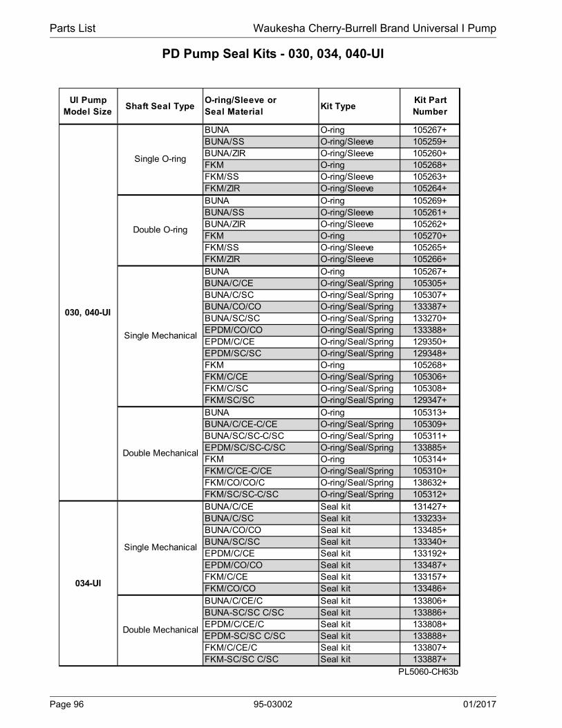
Parts List Waukesha Cherry-Burrell Brand Universal I Pump
PD Pump Seal Kits - 030, 034, 040-UI
UI Pump Model Size
Shaft Seal TypeO-ring/Sleeve or Seal Material
Kit TypeKit Part Number
BUNA O-ring 105267+BUNA/SS O-ring/Sleeve 105259+BUNA/ZIR O-ring/Sleeve 105260+FKM O-ring 105268+FKM/SS O-ring/Sleeve 105263+FKM/ZIR O-ring/Sleeve 105264+BUNA O-ring 105269+BUNA/SS O-ring/Sleeve 105261+BUNA/ZIR O-ring/Sleeve 105262+FKM O-ring 105270+FKM/SS O-ring/Sleeve 105265+FKM/ZIR O-ring/Sleeve 105266+BUNA O-ring 105267+BUNA/C/CE O-ring/Seal/Spring 105305+BUNA/C/SC O-ring/Seal/Spring 105307+BUNA/CO/CO O-ring/Seal/Spring 133387+BUNA/SC/SC O-ring/Seal/Spring 133270+EPDM/CO/CO O-ring/Seal/Spring 133388+EPDM/C/CE O-ring/Seal/Spring 129350+EPDM/SC/SC O-ring/Seal/Spring 129348+FKM O-ring 105268+FKM/C/CE O-ring/Seal/Spring 105306+FKM/C/SC O-ring/Seal/Spring 105308+FKM/SC/SC O-ring/Seal/Spring 129347+BUNA O-ring 105313+BUNA/C/CE-C/CE O-ring/Seal/Spring 105309+BUNA/SC/SC-C/SC O-ring/Seal/Spring 105311+EPDM/SC/SC-C/SC O-ring/Seal/Spring 133885+FKM O-ring 105314+FKM/C/CE-C/CE O-ring/Seal/Spring 105310+FKM/CO/CO/C O-ring/Seal/Spring 138632+FKM/SC/SC-C/SC O-ring/Seal/Spring 105312+BUNA/C/CE Seal kit 131427+BUNA/C/SC Seal kit 133233+BUNA/CO/CO Seal kit 133485+BUNA/SC/SC Seal kit 133340+EPDM/C/CE Seal kit 133192+EPDM/CO/CO Seal kit 133487+FKM/C/CE Seal kit 133157+FKM/CO/CO Seal kit 133486+BUNA/C/CE/C Seal kit 133806+BUNA-SC/SC C/SC Seal kit 133886+EPDM/C/CE/C Seal kit 133808+EPDM-SC/SC C/SC Seal kit 133888+FKM/C/CE/C Seal kit 133807+FKM-SC/SC C/SC Seal kit 133887+
PL5060-CH63b
Single O-ring
030, 040-UI
Single Mechanical
Single Mechanical
Double Mechanical
034-UI
Double O-ring
Double Mechanical
Page 96 95-03002 01/2017

Waukesha Cherry-Burrell Brand Universal I Pump Parts List
PD Pump Seal Kits - 060, 130-UI
UI Pump Model Size
Shaft Seal TypeO-ring/Sleeve or Seal Material
Kit TypeKit Part Number
BUNA O-ring 105279+BUNA/SS O-ring/Sleeve 105271+BUNA/ZI O-ring/Sleeve 105272+FKM O-ring 105280+FKM/SS O-ring/Sleeve 105275+FKM/ZI O-ring/Sleeve 105276+BUNA O-ring 105281+BUNA/SS O-ring/Sleeve 105273+BUNA/ZI O-ring/Sleeve 105274+FKM O-ring 105282+FKM/SS O-ring/Sleeve 105277+FKM/ZI O-ring/Sleeve 105278+BUNA O-ring 105279+BUNA/C/CE O-ring/Seal/Spring 105315+BUNA/C/SC O-ring/Seal/Spring 105317+BUNA/CO/CO O-ring/Seal/Spring 133488+BUNA/SC/SC O-ring/Seal/Spring 133343+EPDM/SC/SC O-ring/Seal/Spring 133344+FKM O-ring 105280+FKM/C/CE O-ring/Seal/Spring 105316+FKM/C/SC O-ring/Seal/Spring 105318+FKM/SC/SC O-ring/Seal/Spring 129346+BUNA O-ring 105323+BUNA/C/CE-C/CE O-ring/Seal/Spring 105319+BUNA/SC/SC-C/SC O-ring/Seal/Spring 105321+FKM O-ring 105324+FKM/C/CE-C/CE O-ring/Seal/Spring 105320+FKM/CO/CO/C O-ring/Seal/Spring 138631+FKM/SC/SC-C/SC O-ring/Seal/Spring 105322+
PL5060-CH64
KeySM Single Mechanical B BUNADM Double Mechanical E EPDMC Carbon V FKMCE Ceramic S SiliconeCO Chrome Oxide K FFKMSC Silicon Carbide T TeflonTC Tungsten CarbideNF Narrow FaceZI Zircon
060, 130-UI
Single O-ring
Double O-ring
Single Mechanical
Double Mechanical
01/2017 95-03002 Page 97
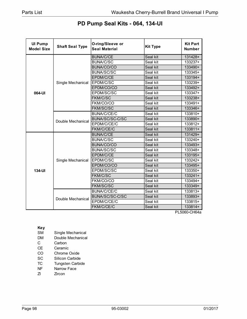
Parts List Waukesha Cherry-Burrell Brand Universal I Pump
PD Pump Seal Kits - 064, 134-UI
UI Pump Model Size
Shaft Seal TypeO-ring/Sleeve or Seal Material
Kit TypeKit Part Number
BUNA/C/CE Seal kit 131428+BUNA/C/SC Seal kit 133237+BUNA/CO/CO Seal kit 133490+BUNA/SC/SC Seal kit 133345+EPDM/C/CE Seal kit 133194+EPDM/C/SC Seal kit 133239+EPDM/CO/CO Seal kit 133492+EPDM/SC/SC Seal kit 133347+FKM/C/SC Seal kit 133238+FKM/CO/CO Seal kit 133491+FKM/SC/SC Seal kit 133346+BUNA/C/CE/C Seal kit 133810+BUNA/SC/SC-C/SC Seal kit 133890+EPDM/C/CE/C Seal kit 133812+FKM/C/CE/C Seal kit 133811+BUNA/C/CE Seal kit 131429+BUNA/C/SC Seal kit 133240+BUNA/CO/CO Seal kit 133493+BUNA/SC/SC Seal kit 133348+EPDM/C/CE Seal kit 133195+EPDM/C/SC Seal kit 133242+EPDM/CO/CO Seal kit 133495+EPDM/SC/SC Seal kit 133350+FKM/C/SC Seal kit 133241+FKM/CO/CO Seal kit 133494+FKM/SC/SC Seal kit 133349+BUNA/C/CE/C Seal kit 133813+BUNA/SC/SC-C/SC Seal kit 133893+EPDM/C/CE/C Seal kit 133815+FKM/C/CE/C Seal kit 133814+
PL5060-CH64a
KeySM Single Mechanical B BUNADM Double Mechanical E EPDMC Carbon V FKMCE Ceramic S SiliconeCO Chrome Oxide K FFKMSC Silicon Carbide T TeflonTC Tungsten CarbideNF Narrow FaceZI Zircon
Single Mechanical
Double Mechanical
134-UI
Single Mechanical
Double Mechanical
064-UI
Page 98 95-03002 01/2017

Waukesha Cherry-Burrell Brand Universal I Pump Parts List
PD Pump Seal Kits - 220-UI
UI Pump Model Size
Shaft Seal TypeO-ring/Sleeve or Seal Material
Kit TypeKit Part Number
BUNA O-ring 105291+BUNA/SS O-ring/Sleeve 105283+BUNA/ZI O-ring/Sleeve 105284+FKM O-ring 105292+FKM/SS O-ring/Sleeve 105287+FKM/ZI O-ring/Sleeve 105288+BUNA O-ring 105293+BUNA/SS O-ring/Sleeve 105285+BUNA/ZI O-ring/Sleeve 105286+FKM O-ring 105294+FKM/SS O-ring/Sleeve 105289+FKM/ZI O-ring/Sleeve 105290+BUNA O-ring 105291+BUNA/C/CE O-ring/Seal/Spring 105325+BUNA/C/SC O-ring/Seal/Spring 105327+BUNA/SC/SC O-ring/Seal/Spring 114949+BUNA/CO/CO O-ring/Seal/Spring 121365+EPDM/SC/SC O-ring/Seal/Spring 133353+FKM O-ring 105292+FKM/C/CE O-ring/Seal/Spring 105326+FKM/C/SC O-ring/Seal/Spring 105328+FKM/SC/SC O-ring/Seal/Spring 133352+BUNA O-ring 105333+BUNA/C/CE/C/CE O-ring/Seal/Spring 105329+BUNA/SC/SC/C/SC O-ring/Seal/Spring 105331+EPDM/C/CE O-ring/Seal/Spring 133191+EPDM/C/CE/C O-ring/Seal/Spring 133816+FKM O-ring 105334+FKM/C/CE/C/CE O-ring/Seal/Spring 105330+FKM/SC/SC/C/SC O-ring/Seal/Spring 105332+BUNA/C/CE Seal Kit 133160+BUNA/SC/SC Seal Kit 133354+EPDM/SC/SC Seal Kit 133356+FKM/SC/SC Seal Kit 133355+BUNA/C/CE/C Seal Kit 133817+BUNA/SC/SC-C/SC Seal Kit 133897+EPDM/C/CE/C Seal Kit 133819+FKM/C/CE/C Seal Kit 133818+
PL5060-CH64b
KeySM Single Mechanical SC Silicon CarbideDM Double Mechanical TC Tungsten CarbideC Carbon NF Narrow FaceCE Ceramic ZI ZirconCO Chrome Oxide K FFKM
T Teflon
Single Mechanical
Double Mechanical
224-UI
220-UI
Single O-ring
Double O-ring
Single Mechanical
Double Mechanical
01/2017 95-03002 Page 99

Parts List Waukesha Cherry-Burrell Brand Universal I Pump
Universal I PD Pump Vented Covers
Manual Vented Cover, 006-134-UI
102104
107 105
103106
108
101
PD100-298a
Pneumatic Diaphragm Vented Cover
111110
108
101
PD100-299a
Manual Vented Cover, 220-224 UI
102 104105
103
106 109 107 108 101
PD100-597
Pneumatic Piston Vented Cover
116115
114113
101
112117
PD100-300a
Page 100 95-03002 01/2017

Waukesha Cherry-Burrell Brand Universal I Pump Parts List
Universal I PD Pump Vented Covers
Notes:* Recommended Spare Parts
1. 060, 064, 130, 134-UI: pumps older than approx. March 2000 used p/n AD0072000.
2. 060, 064, 130, 134-UI: for pumps older than approx. March 2000, use p/n CD0073000.
3. 006, 014, 015, 018, 024-UI: pumps older than approx. March 2000 used p/n AD0076L00 for 0-20 psi 060, 064, 130, 134-UI: pumps older than approx March 2000 used p/n AD0076000 for 20-60 psi 220, 224-UI: pumps older than approx March 2000 used p/n ABB076200 for 100-200 psi.
4. 060, 064, 130, 134-UI: pumps older than approx March 2000 used p/n ABB076200 for 100-200 psi. 220, 224-UI: pumps older than approx March 2000 used p/n GD0076100
5. 060, 064, 130, 134-UI: pumps older than approx March 2000 used p/n CD0075000.
9. Quad Ring and O-Ring can be interchanged.
12. Applies to the 220-UI and 224-UI only.
13 Vented cover is not used on the 033-UI, 133-UI, or 223-UI pump.
006, 014, 015, 018,
024-UI
030, 034, 040-UI
060, 064, 130, 134-UI
220, 224-UI
101 Vented Cover 1 AD0002VS0 BD0002VS0 CD0002VS0 GD0002VS0
102 Adjusting Screw 1 113657+ GD0072100 1
103 Spring Plunger 1 113397+ GD0073000 2
104 Locknut 1Spring, Medium (< 150 psi) 113523+ 113400+ 3Spring, High (> 150 psi) 113400+ 113524+ 4
106 Diaphragm Bushing 1 CD0077000 GD0077000
107 Cover Nut 1 113398+ GD0075000 5
* 108Rubber Diaphragm, Buna N
1 CD0078000 GD0078000
O-ring, Buna N N70261
O-ring, FKM V70261
O-ring, Silicone S75261
101 Vented Cover 1 AD0002VS0 BD0002VS0 CD0002VS0 N/A
* 108 Diaphragm, Buna N 1 CD0078000 N/A
110 Diaphragm Bushing 1 CD0077P00 N/A
111 Cover Nut 1 CD0075P00 N/A
101 Vented Cover 1 AD0002VS0 BD0002VS0 CD0002VS0 GD0002VS0
112 Piston 1 CD0073P10 GD0073P10
* 113O-Ring, Bushing Seal, Buna N
1 N70239 N70261
114 Diaphragm Bushing 1 CD0077P10 GD0077P10
* 115 O-Ring, Nut Seal, Buna N 1 N70240 N70261
116 Cover Nut 1 CD0075P10 GD0075P10* Piston Seal, Quad Ring 1 CD0133000 GD0133000 9
* Piston Seal, O-Ring 1 N70236 N70258 9PL5060-CH115
N/A 12*
117
AD0077P10
AD0133000
105
AD0078000
AD0077P00
AD0075P00
AD0073P10
N70223
109 1 N/A
1
NOTESQTY. PER
PUMP
AD0075000
AD0078000
GD0074000
ITEM NO.
DESCRIPTION
ABB076100AD0077000
PART NO.
MANUAL VENTED COVER
PNEUMATIC DIAPHRAGM VENTED COVER
PNEUMATIC PISTON VENTED COVER
N70218
AD0072000
AD0073000
AD0074000AD0076000
N70224AD0075P10
01/2017 95-03002 Page 101

Parts List Waukesha Cherry-Burrell Brand Universal I Pump
Tru-Fit™ Universal I PD Pumps Parts List
OPPOSITE SIDE
33D44A33E
PD100-433P
127
3
4A
006, 014, 015 018, 024 030, 034 0403 Gear Case, CI
4A Gear Case Cover, Adapter7 Drive Shaft 119174+ 119175+ 119176+ 119177+
1/4-20 x 1" HHCS5/16-18 x 1-1/8" HHCS5/16" x 3/4" lg. SHSB3/8" x 3/4" lg. SHSBFlat Washer, 5/16"Flat Washer, 3/8"
060, 064 130, 134 220, 224 320, 3243 Gear Case, CI 118988+ 118989+
4A Gear Case Cover, Adapter7 Drive Shaft 119178+ 119179+ 119180+ 119181+
3/8-16 x 1-1/2" HHCS N/A1/2-13 x 1-1/2" HHCS 30-1031/2" x 1" lg. SHSB N/A5/8" x 1" lg. SHSB 30-693
44A Flat Washer, 1/2"PL5060-CH65
ITEM NO. DESCRIPTION
Pump SizeDESCRIPTIONITEM NO.
33E
33D
Pump Size
118987+118983+
33E
44A
33D
118986+118982+
121687+118678+
30-9330-237
N/A 43-30
S/N Req'd
43-31
30-50N/A
30-692N/A
N/AN/A
30-690N/A
43-246
N/A30-691
N/A
Note:Item 12 is not included with item 4A; it is reused from the existing gearcase seal. See parts lists/diagrams on previous pages for the various pump models.
Page 102 95-03002 01/2017

Waukesha Cherry-Burrell Brand Universal I Pump Parts List
Shaft Assemblies with Pressed-on Bearings
DESCRIPTIONQTY. PER
PUMP
PART NO.: Pumps
shipped before 7/30/01
PART NO.: Pumps
shipped after 7/30/01
Notes
006-014-015-UI Drive Shaft & Bearing Assy. 1 POA 137262+ 1006-014-015-UI Short Shaft & Bearing Assy. 1 POA 137265+ 1018-024-UI Drive Shaft & Bearing Assy. 1 137263+ 137264+ 1018-024-UI Short Shaft & Bearing Assy. 1 137266+ 137267+ 1030-034-UI Drive Shaft & Bearing Assy., Std 1 137273+ 137274+ 1030-034-UI Drive Shaft & Bearing Assy., Optional 17-4PH 1 POA POA 1030-034-UI Short Shaft & Bearing Assy., Std. 1 137496+ 137275+ 1030-034-UI Short Shaft & Bearing Assy., Optional 17-4PH 1 POA POA 1033A-UI Drive Shaft & Bearing Assy., Std. 1 137495+ POA 1033A-UI Short Shaft & Bearing Assy., Std. 1 137276+ POA 1040-UI Drive Shaft & Bearing Assy., Std. 1 1040-UI Drive Shaft & Bearing Assy., Optional 17-4PH 1 1040-UI Short Shaft & Bearing Assy., Std. 1 1040-UI Short Shaft & Bearing Assy., Optional 17-4PH 1 1060-064-UI Drive Shaft & Bearing Assy. 1 1060-064-UI Drive Shaft & Bearing Assy., Optional 17-4PH 1 1060-064-UI Short Shaft & Bearing Assy. 1 1060-064-UI Short Shaft & Bearing Assy., Optional 17-4PH 1 1130-134-UI Drive Shaft & Bearing Assy. 1 1130-134-UI Drive Shaft & Bearing Assy., Optional 17-4PH 1 1130-134-UI Short Shaft & Bearing Assy. 1 1130-134-UI Short Shaft & Bearing Assy., Optional 17-4PH 1 1133A-UI Drive Shaft & Bearing Assy. 1 1133A-UI Drive Shaft & Bearing Assy., Optional 17-4PH 1 1133A-UI Short Shaft & Bearing Assy. 1 1133A-UI Short Shaft & Bearing Assy., Optional 17-4PH 1 1220-224-UI Drive Shaft & Bearing Assy., Std. 1 1220-224-UI Drive Shaft & Bearing Assy., Optional 17-4PH 1 1220-224-UI Short Shaft & Bearing Assy., Std. 1 1220-224-UI Short Shaft & Bearing Assy., Optional 17-4PH 1 1320/324UI Drive Shaft & Bearing Assy., Std. 1 137314+ 137515+ 1, 2320/324-UI Drive Shaft & Bearing Assy., Optional 17-4PH 1 POA POA 1, 2320/324UI Short Shaft & Bearing Assy., Std. 1 137315+ 137516+ 1, 2320/324-UI Short Shaft & Bearing Assy., Optional 17-4PH 1 POA POA 1, 2
PL5060-CH127
POAPOAPOAPOA
137277+POA
137279+137280+137278+138511+137281+137282+
POAPOA
137288+
POAPOA
137285+137286+137287+
Notes:
1. All assemblies include items:7 or 8 (Drive or Short Shaft), 15 (Rear Bearing), 16 (Front Bearing), 17 (Gear key), 29 (Gear to Rear Bearing Spacer), and 30 (Front Bearing Spacer), assembled together. See model-specific parts lists on the previous pages for drawings with item numbers
2. For 320/324-UI pumps: These assemblies also include: 30A (Bearing Spacer), 31 (Grease Retainer), and 41 (Locknut), which are assembled with the items listed in Note 1, above.To use these shaft and bearing assemblies in a gearbox shipped before 7/30/01, you will also need part numbers STD119000 x1 and 102470+ x1. All these items are available (unassembled) in the kits on page 83.
POA = Contact SPX FLOW Customer Service for part number.
01/2017 95-03002 Page 103

Parts List Waukesha Cherry-Burrell Brand Universal I Pump
Grease Seal, Bearing Retainer, O-Ring Seal Carrier Part No. Reference
before 7/30/01
Approx. 7/30/01-7/12/04
after 7/12/04 (Newest)
14Grease Seal, Bearing Retainer, standard gearcase
121679+ 8
14Grease Seal, Bearing Retainer, SS gearcase or Bearing Isolator
4
32Bearing Retainer, Front SS, for standard gearcase
120332+ 8
32Bearing Retainer, Front SS, for SS Gearcase or Bearing Isolator
4
Bearing Isolator Kit X06636-1 884 O-Ring Seal Carrier 015034001+
14 Grease Seal, Bearing Retainer 000030015+ 8
32Bearing Retainer, Front SS, for standard gearcase
8
32Bearing Retainer, Front SS, for SS Gearcase or Bearing Isolator
101811+ 122337+ 2, 8
Bearing Isolator Kit X06558-1 N/A X06639-1 2, 884 O-Ring Seal Carrier 030034001+
14 Grease Seal, Bearing Retainer 832 Bearing Retainer, Front CTD 123531+ 532 Bearing Retainer, Front SS, for std. lip seal 6, 8
32Bearing Retainer, Front SS, used with bearing isolators.
6, 8
Bearing Isolator Kit, SS X06614-2 884 O-Ring Seal Carrier 060034001+
14 Grease Seal, Bearing Retainer 121681+ 132 Bearing Retainer, Front CTD N/A use 121829+32 Bearing Retainer, Front SS, for std. lip seal 8
32Bearing Retainer, Front SS, used with bearing isolators.
3, 7, 8
Bearing Isolator Kit 3, 7, 884 O-Ring Seal Carrier 220034001+
14 Grease Seal, Bearing Retainer 121681+ 132 Bearing Retainer, Front CTD N/A, use 123533+ 832 Bearing Retainer, Front SS, for std. gearcase 123533+ 8
32Bearing Retainer, Front SS, used with bearing isolators.
3, 7
Bearing Isolator Kit, SS 3, 7, 8
PL5060-CH114
030080000+
121141+
120333+
UI Model
NumberItem Description
For pumps manufactured:
Notes
006, 014, 015, 018, 024
000030018+
015034000+
101716+
015080000+
101810+
X06638-1
030, 034, 040
121680+
030034000+
060, 064, 130, 134
000030009+N/A, use 123531+
121828+
101812+
N/A, use X06614-2060034000+
220034000+
320, 324 N/A; use 121681+0H1080000
118365+
X06634-3
121829+
101813+
X06634-2
220, 224 N/A; use 121681+220080000+
Notes: CTD = Coated Steel; SS = Stainless Steel1. Pumps manufactured up through 1993 may take STD030005 instead (used old-style shafts). Verify s/n to confirm.2. 101811+ is used with bearing isolators. If isolator is needed, use part # X06639 (no kit available). Check gearcase s/n.
Kit X06639-1 contains bearing retainer 122337+3. Isolator kit X06634-2 contains 101813+ bearing retainer; Isolator kit X06634-3 contains 121141+ bearing retainer.4. 101810+ bearing retainer is used with 101716+ grease seal.5. 123531+ is available until stock is depleted, then will be replaced by 121828+6. 101812+ is used with bearing isolators; for std. lip seal, use part # 121828+7. When changing to this bearing isolator, if it rubs and is very difficult to turn over, add a .010 shim to each shaft, on top
of the bearing in the pump, between the bearing and the retainer.8. When changing a pump supplied WITHOUT a bearing isolator, to one WITH a bearing isolator, order the isolator kit.
Components of this kit must be used together. If adding a bearing isolator to an assembly, discard the old retainer.
Page 104 95-03002 01/2017
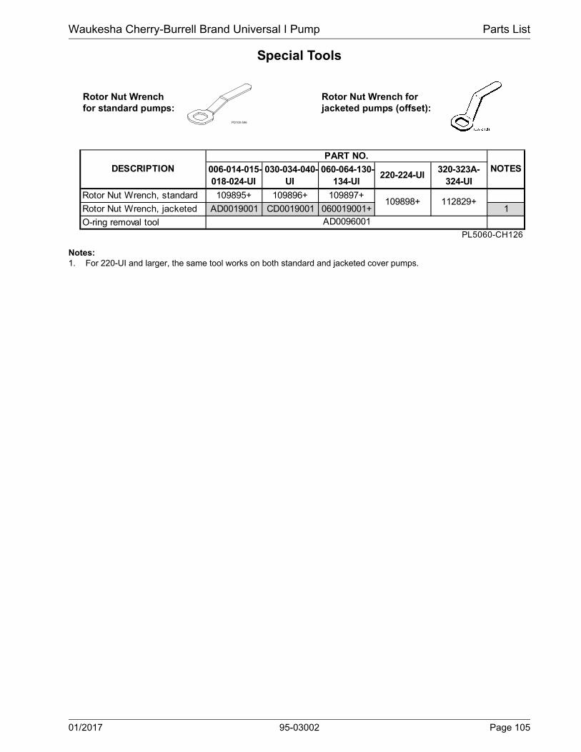
Waukesha Cherry-Burrell Brand Universal I Pump Parts List
Special Tools
PD100-596
006-014-015-018-024-UI
030-034-040-UI
060-064-130-134-UI
220-224-UI320-323A-
324-UI
Rotor Nut Wrench, standard 109895+ 109896+ 109897+
Rotor Nut Wrench, jacketed AD0019001 CD0019001 060019001+ 1
O-ring removal toolPL5060-CH126
AD0096001
NOTESDESCRIPTIONPART NO.
109898+ 112829+
Notes:1. For 220-UI and larger, the same tool works on both standard and jacketed cover pumps.
Rotor Nut Wrench for standard pumps:
Rotor Nut Wrench for jacketed pumps (offset):
01/2017 95-03002 Page 105

Pump Dimensions Waukesha Cherry-Burrell Brand Universal I Pump
Pump Dimensions
Universal I PD Pump Dimensions
12 PLACESG1
PUMP MOUNTING PADSVIEW A-A OF TOP & BOTTOM
CP3 PNEUMATIC VENTED COVER-DIAPHRAGM
CP4 MANUAL VENTED COVER
CP2 PNEUMATIC VENTED COVER-PISTON
CP1 JACKETED COVER
CP STANDARD COVER
L
HT
A A OPTIONAL UPPER SHAFT
K-KEY
M
N
J
U
I
B
R F
AA
J
M MOUNTING PADSIDE MOUNT
2X
X
AO
PORT
O
A
E
INLET
OUTLET
1"-11 1/2 N.P.T., MODELS 060, 130
THIS SIDE
OTHER SIDE
G
S TYP
T1 H1
S1
SS1
PO
RT
C L
E
3/4"-14 N.P.T., MODELS 006-030
OPTIONAL MOUNTING PAD LOCATION
M
J
EYEBOLTS,MODELS060-320
D
PD100-533
Page 106 95-03002 01/2017

Waukesha Cherry-Burrell Brand Universal I Pump Pump Dimensions
Universal I PD Pump Dimensions
UI Model
A AA AO B CP CP1 CP2 CP3 CP4 D E F H H1 I
inch 4.75 1.95 8.30 3.75 12.04 13.47 13.53 13.62 15.25 5.50 1.94 2.31 2.50 2.50 7.66
mm 121 50 211 95 306 342 344 346 387 140 49 59 64 64 194
inch 4.75 2.18 8.30 3.75 12.46 13.90 13.95 14.04 15.67 5.50 1.94 2.31 2.50 2.50 7.66
mm 121 55 211 95 316 353 354 357 398 140 49 59 64 64 194
inch 6.25 2.78 10.29 4.25 14.58 16.42 15.98 16.07 17.67 6.86 2.31 2.56 1.81 2.75 8.83
mm 159 71 261 108 370 417 406 408 449 174 59 65 46 70 224
inch 6.25 2.99 10.29 4.25 14.96 16.80 16.36 16.45 18.05 6.86 2.31 2.56 1.81 2.75 8.83
mm 159 76 261 108 380 427 416 418 458 174 59 65 46 70 224
inch 8.25 4.14 15.31 5.87 18.91 20.69 20.47 20.76 22.07 9.56 3.50 4.12 3.00 4.13 10.99
mm 210 105 389 149 480 526 520 527 561 243 89 105 76 105 279
inch 8.25 4.78 15.31 5.87 19.85 21.63 21.42 21.70 23.01 9.56 3.50 4.12 3.00 4.13 10.99
mm 210 121 389 149 504 549 544 551 584 243 89 105 76 105 279
inch 8.5 3.69 19.13 9.00 23.37 -- 26.07 -- 27.87 12.38 3.75 7.25 5.38 5.38 14.80
mm 216 94 486 229 594 -- 662 -- 708 314 95 184 137 137 376
inch 12.00 4.12 22.38 11.63 30.17 -- -- -- -- 13.88 5.25 8.00 5.38 5.38 17.80
mm 305 105 568 295 766 -- -- -- -- 353 133 203 137 137 452
UI Model
J
K+.002-.000
L M N O R S S1 SS1 T T1
U+.002-.000
X 2X
inch 2.93 .1875 9.61 2.12 2.00 4.21 2.79 1.00 1.00 1.00 2.51 2.51 .875 3.49 6.97 52 lb
mm 74 4.763 244 54 51 107 71 25 25 25 64 64 22.23 89 177 24 kg
inch 2.93 .1875 9.84 2.12 2.00 4.21 3.02 1.00 1.00 1.00 2.74 2.74 .875 3.55 7.09 54 lb
mm 74 4.763 250 54 51 107 77 25 25 25 70 70 22.23 90 180 24 kg
inch 3.56 .25 11.61 2.62 2.32 5.21 3.84 1.12 1.12 1.12 4.00 3.59 1.250 4.25 8.50 100 lb
mm 90 6.35 295 67 59 132 98 28 28 28 102 91 31.75 108 216 45 kg
inch 3.56 .25 11.99 2.62 2.32 5.21 4.22 1.12 1.12 1.12 4.38 3.97 1.250 4.31 8.62 106 lb
mm 90 6.35 305 67 59 132 107 28 28 28 111 101 31.75 109 219 48 kg
inch 5.06 .375 15.14 3.50 2.25 7.31 5.01 1.75 2.00 1.75 5.62 5.01 1.625 5.37 10.75 255 lb
mm 129 9.525 385 89 57 186 127 44 51 44 143 127 41.28 136 273 116 kg
inch 5.06 .375 15.77 3.50 2.25 7.31 5.65 1.75 2.00 1.75 6.25 5.66 1.625 5.37 10.75 260 lb
mm 129 9.525 401 89 57 186 144 44 51 44 159 144 41.28 136 273 118 kg
inch 6.38 .50 18.49 4.50 2.75 9.38 4.44 2.69 2.69 2.69 6.00 6.00 2.000 6.63 13.25 450 lb
mm 162 12.7 470 114 70 2.38 113 68 68 68 152 152 50.80 168 337 204 kg
inch 6.88 .625 21.92 5.06 4.06 10.38 5.37 2.69 2.69 2.69 8.49 8.49 2.375 8.00 16.00 795 lb
mm 175 15.875 557 129 103 264 136 68 68 68 213 213 60.45 203 406 361 kg
PD100-437c
Notes* WT = Standard CoverIMDA ports are standard; other laster-w eld ports are available for models 006 through 220.
.53
--
G
.41, SLOT
10, SLOT
.41, SLOT
10, SLOT
.41, SLOT
10, SLOT
.41, SLOT
10, SLOT
018
030
040
220
320
.53
13
6" 150# FLG
060
130
006,015
006,015
018
030
040
220
2-1/2" IMDA
4" IMDA
--
1-1/2" IMDA
--
2" IMDA
--
13
.53, SLOT
13, SLOT
.66
17
--
320
Port
1-1/2" IMDA
--
1-1/2" IMDA
--
060
1303" IMDA
--
G1
5/16-18x .62
--
5/16-18x .62
--
3/8-16x .62
--
3/8-16x .62
--
1/2-13x 1.00
--
1/2-13x 1.00
WT*
--
1/2-13x .88
--
1/2-13x .88
--
01/2017 95-03002 Page 107

Pump Dimensions Waukesha Cherry-Burrell Brand Universal I Pump
Universal I PD Pump Dimensions - Rectangular Flange with Pedestal
014 & 324 ONLY
.88 (22), MODEL 324
STYLE FOR MODELS
MODELS 014, 5/16-18
.38 (10), MODELS 014 & 024
SMLH DRIVESTANDARD
OU
TLET
PO
RT C
L
VIEW A-A OF SIDEPUMP MOUNTING PAD
MODELS 064-324, 1/2-13MODELS 034, 3/8-16
.50 (13), MODELS 034-224
LPO
RT C
PBPD
PA
ON 014 THRU 224OTHER PORTS OPTIONAL
S1
T1
PBPD
PA
PC
HA
FACA
C FB
CBCC
Z
P-IMDA, NOMINAL
2X
X
AOL
HAO
H
EQ
A
Q
S1
HB1
OUTL
ET O
NLY
LL
SSS
SS S
CP2 PNEUMATIC VENTED COVER-PISTON
CP4 MANUAL VENTED COVER
CP STANDARD COVER
L
T HB
K-KEY
N
U
J
LDHD
IBAA
R F
CP3 PNEUMATIC VENTED COVER-DIAPHRAGM
CP1 JACKETED COVER
PUMP064
A A
PD100-549
Page 108 95-03002 01/2017

Waukesha Cherry-Burrell Brand Universal I Pump Pump Dimensions
Universal I PD Pump Dimensions - Rectangular Flange with Pedestal
UI RF Model
A AA AOH AOL B C CA CB CC CP CP1 CP2 CP3 CP4
inch 6.75 1.95 - 12.50 4.13 .50 1.62 6.50 .50 12.04 13.47 13.53 13.62 15.25
mm 171 50 - 318 105 13 41 165 13 306 342 344 346 387
inch 6.75 2.18 - 12.50 4.13 .50 2.00 7.00 .50 12.46 13.9 13.95 14.04 15.67
mm 171 55 - 318 105 13 51 178 13 316 353 354 357 398
inch 8.00 2.88 - 12.75 4.25 .62 1.88 10.75 .62 14.58 16.42 15.98 16.07 17.67
mm 203 73 - 324 108 16 48 273 16 370 417 406 408 449
inch 11.75 4.35 18.44 13.94 7.00 .50 4.00 12.20 .52 18.91 20.69 20.47 20.76 22.07
mm 298 110 468 354 178 13 102 310 13 480 526 520 527 561
inch 11.75 5.00 18.44 13.94 7.00 .78 3.00 14.00 0.63 19.85 21.63 21.42 21.7 23.01
mm 298 127 468 354 178 20 76 356 16 504 549 544 551 584
inch 15.00 4.75 23.75 19.75 9.50 .63 4.37 16.75 .63 23.37 - 26.07 - 27.87
mm 381 121 603 502 241 16 111 425 16 594 - 662 - 708
inch 18.00 6.56 - 36.00 12.00 .63 8.25 18.50 .69 30.17 - - - -
mm 457 167 - 914 305 16 210 470 18 766 - - - -
UI RF Model
DH DL E F FA FB H HA HB HB1 I JK
+.002-.000
L
inch - 8.88 .38 2.31 2.63 7.50 .41 .41 2.50 2.50 7.66 2.12 1875 9.61mm - 226 10 59 67 191 10 10 64 64 195 54 4.763 244inch - 8.88 .38 2.31 3.00 8.00 .41 .41 2.50 2.50 7.66 2.12 1875 9.84mm - 226 10 59 76 203 10 10 64 64 195 54 4.763 250inch - 8.88 .38 3.00 3.12 12.0 .44 .53 2.75 1.81 8.49 2.63 .25 11.36mm - 226 10 76 79 305 11 13 70 46 216 67 6.35 289inch 13.5 9.00 .50 5.550 5.00 13.23 .56 .53 7.13 3.00 10.77 3.50 .375 15.16mm 343 229 13 140 127 336 14 13 105 76 274 89 9.525 385inch 13.5 9.00 .50 5.50 4.55 15.25 .56 .53 4.13 3.00 10.77 3.50 .375 15.78mm 343 229 13 140 116 387 14 13 105 76 274 89 9.525 401inch 17.5 13.50 .63 8.25 5.63 18.00 .56 .53 5.38 5.38 13.74 4.50 .50 18.49mm 445 343 16 210 143 457 14 13 137 137 349 114 12.70 470inch - 27.13 .75 9.50 9.50 19.88 .69 .66 5.38 5.38 16.86 5.06 .625 23.42
mm - 689 19 241 241 505 18 17 137 137 428 129 15.875 595
UI RF Model
S1 SS T T1U
+.002-.000
X 2X Z
inch 1.00 1.00 2.51 2.51 .875 3.63 7.11 1.28mm 25 25 64 64 22.23 92 181 33inch 1.00 1.00 2.74 2.74 .875 3.63 7.11 1.28mm 25 25 70 70 22.23 92 181 33inch 1.12 1.12 3.35 3.76 1.250 3.88 8.12 1.65mm 28 28 85 96 31.75 99 206 42inch 1.75 1.75 5.01 5.60 1.625 4.94 10.31 2.25mm 44 44 127 142 41.28 125 262 57inch 1.75 1.75 5.65 6.25 1.625 4.94 10.31 2.25mm 44 44 144 159 41.28 125 262 57inch 2.69 2.69 6.00 6.00 2.000 6.25 12.87 3.00mm 68 68 152 152 50.80 159 327 76inch 2.69 2.69 9.87 9.87 2.375 8.87 17.88 3.50
mm 68 68 251 251 60.33 225 454 89
Notes PD100-437b*WT Weight measurement is with Standard Cover with Standard Universal FootModel 324 has 8 bolt holes in rectangular flange. Outlet port is a round flange.Dimension AO is with the tallest pedestal. Optional heights are available.CP4 is the maximum dimension for all vented and jacketed cover options.
352 lb
116 lb280 kg127 lb505 kg229 lb
775 kg6" 150# FLG
--
WT*
47 kg21 lb49 kg22 lb
100 kg45 lb
255 kg
PortSize
1-1/2"--
1-1/2"--2"
224
324
064
134
324
014
024
134
224
3"--4"--
034
064
--2-1/2"
--
324
014
024
034
014
024
034
064
134
224
01/2017 95-03002 Page 109

Pump Dimensions Waukesha Cherry-Burrell Brand Universal I Pump
Tru-Fit™ Universal I PD Pump Dimensions
L P
M
N
H
E
G
J
F
K
T1 S
T
(3) "U" TAPPEDHOLES
B/2
B
A
C
D
V
V/2
PD100-436bP
Page 110 95-03002 01/2017

Waukesha Cherry-Burrell Brand Universal I Pump Pump Dimensions
Tru-Fit™ Universal I PD Pump Dimensions
Tru-Fit™
Universal I Pump Size
A B C D2 E F G H J K
inch 12.0 10.0 9.15 6.97 7.87 13.25 2.01 18.0 2.43 10.08
mm 305 254 232 177 200 337 51 457 62 256
inch 12.0 10.0 9.15 6.97 7.87 13.25 2.01 18.0 2.43 10.08
mm 304 254 232 177 200 337 51 457 62 256
inch 12.0 10.0 9.15 7.10 7.87 13.25 2.25 18.0 2.62 10.31
mm 304 254 232 180 200 337 57 457 67 262
inch 14.0 12.0 10.02 8.51 8.37 15.11 2.59 20.0 2.97 12.47
mm 356 304 255 216 213 384 66 508 75 317
inch 14.0 12.0 10.02 8.62 8.37 15.11 2.97 20.0 2.97 12.84
mm 356 305 255 219 213 384 75 508 75 326
inch 18.0 16.0 12.0 10.74 9.75 20.0 3.01 28.0 3.77 17.39
mm 457 406 305 273 248 508 76 711 96 442
inch 18.0 16.0 12.0 10.74 9.75 20.0 3.64 28.0 4.08 18.02
mm 457 406 305 273 248 508 92 711 104 458
inch 20.0 18.0 14.5 13.25 11.5 23.25 3.51 36.0 4.99 19.76
mm 508 457 368 337 292 591 89 914 127 502
Tru-Fit™
Universal I Pump Size
L M1 N1 P1 PortSize
S T T1 U V
inch 12.51 27.60 15.56 10.92 1-1/2" 5.44 2.12 2.51 5/16-18 x .62 2.00
mm 318 701 395 227 -- 138 54 64 N/A 51
inch 12.51 27.60 15.56 10.92 1-1/2" 5.44 2.12 2.51 5/16-18 x .62 2.00
mm 318 701 395 227 -- 138 54 64 N/A 51
inch 12.93 28.02 15.56 10.92 1-1/2" 5.44 2.12 2.74 5/16-18 x .62 2.00
mm 328 712 395 227 -- 138 54 70 N/A 51
inch 15.44 33.67 18.65 13.74 1-1/2" 5.81 2.62 3.59 3/8-16 x .62 2.25
mm 392 855 474 349 -- 148 67 91 N/A 57
inch 15.81 34.04 18.65 13.74 2" 5.81 2.62 3.97 3/8-16 x .62 2.25
mm 402 865 474 349 -- 148 67 101 N/A 57
inch 21.16 43.77 22.02 17.16 2-1/2" 8.13 3.50 5.01 1/2-13 x .88 3.50
mm 537 1112 559 436 -- 207 89 127 N/A 89
inch 22.10 44.71 22.02 17.16 3" 8.13 3.50 5.66 1/2-13 x .88 3.50
mm 561 1136 559 436 -- 207 89 144 N/A 89
inch 24.51 52.23 27.68 20.40 4" 10.00 4.50 6.00 1/2-13 x 1.0 5.38
mm 623 1327 703 518 -- 254 114 152 N/A 137PD100-437
040
060
130
220
130
220
006
015
018
030
006
015
018
030
040
060
01/2017 95-03002 Page 111

Troubleshooting Waukesha Cherry-Burrell Brand Universal I Pump
Troubleshooting
PROBLEM POSSIBLE CAUSE SUGGESTED ACTION
No flow, pump rotors are not turning
Drive motor not running. Check resets, fuses, circuit breakers.
Keys sheared or missing. Replace.
Drive belts, power transmission components slipping or broken.
Replace or adjust.
Pump shaft, keys, or gears sheared.
Inspect: and replace parts as necessary.
No flow, pump rotors are turning
Rotors turn in the wrong direction.
Check motor hookup to reverse motor rotation.
Relief valve not properly adjusted, or held open by foreign material.
Adjust or clear valve.
Suction port is blocked, not allowing flow to the pump.
Check all inlet valves, strainers, tank outlet ports.
No flow, pump not priming Valve closed in inlet line. Open valve.
Inlet line clogged or restricted. Clear line, clean filters, etc.
Air leaks due to bad gaskets or pipe connections.
Replace gaskets; check lines for leakage (can be done by air pressure or by filling with liquid and pressurizing with air).
Pump speed too slow. Increase pump speed.
Pump speed too fast for high-viscosity liquid.
Decrease pump speed.
Liquid drains or siphons from system during off periods.
Use foot valve or check valves.Filling inlet lines with material before startup may solve startup priming problems due to no material in system.
"Air" lock caused by fluids which "gas off", or vaporize, or allow gas to come out of solution during off periods.
Install and use a manual or automatic air bleed from pump or lines near pump.
Extra clearance rotors, worn pump.
Increase pump speed, use foot valve to improve priming.
Replace worn rotors.
Net inlet pressure available too low.
Check Net Inlet Pressure Available & Net Inlet Pressure Required. Change inlet system as needed.
Page 112 95-03002 01/2017

Waukesha Cherry-Burrell Brand Universal I Pump Troubleshooting
PROBLEM POSSIBLE CAUSE SUGGESTED ACTION
No flow, pump not priming, cont’d
On "Vacuum'' inlet system: On initial start-up, atmospheric "blow back'' prevents pump from developing enough differential pressure to start flow.
Install check valve in discharge line.
Insufficient flow Speed too low or too high to obtain desired flow.
Check flow-speed curve (available from SPX FLOW customer service) and adjust as necessary.
Air leak due to bad seals, pipe connections, or other equipment.
Replace seals, check inlet fittings.
Insufficient flow—flow being bypassed somewhere
Flow diverted in branch line, open valve, etc.
Check system and controls
Relief valve not adjusted or jammed.
Clear or adjust valve.
Insufficient flow—high slip Hot (HC) or extra clearance rotors on "cold" fluid and/or low viscosity fluid.
Replace with standard clearance rotors.
Worn pump. Increase pump speed (within limits). Replace rotors, have pump remanufactured.
High pressure. Reduce pressure by adjusting system settings or hardware.
Fluid vaporization (“starved'' pump inlet)
Strainers, foot valves, inlet fittings or lines clogged.
Clear lines. If problem continues, inlet system may require changing.
Inlet line size too small, inlet line too long. Too many fittings or valves. Foot valve, strainers too small.
Increase inlet line size. Reduce length, minimize direction and size changes, reduce number of fittings.
NIPA - Net Inlet Pressure Available at Pump is too low.
Raise liquid level in source tank to increase Net Inlet Pressure (NIPA).
Increase Net Inlet Pressure Available at Pump by raising or pressurizing source tank.
Select larger pump size with lower Net Inlet Pressure Required.
Fluid viscosity greater than expected.
Reduce pump speed and accept lower flow, or change system to reduce line losses.
Change temperature of product to reduce viscosity.
01/2017 95-03002 Page 113

Troubleshooting Waukesha Cherry-Burrell Brand Universal I Pump
PROBLEM POSSIBLE CAUSE SUGGESTED ACTION
Fluid vaporization, cont’d Fluid temperature higher than expected (vapor pressure higher).
Reduce temperature, reduce speed and accept lower flow or change system to increase Net Inlet Pressure Available.
Noisy operation Cavitation
High fluid viscosity. High vapor pressure fluid. High temperature.
Slow down pump, reduce temperature, change system setup.
Net Inlet Pressure Avail-able less than Net Inlet Pressure Required.
Increase NIPA - Net Inlet Pressure Required or reduce NIPR - Net Inlet Pressure Required. Contact SPX FLOW application engineering if necessary.
Air or gas in fluid
Leaks in the pump or piping.
Correct leaks.
Dissolved gas or naturally aerated products.
Minimize discharge pressure (also see "Cavitation," above).
Noisy operation caused by mechanical problems
Rotor to body contact
Improper assembly of pump.
Check clearances and adjust shimming.
Distortion of pump due to improper piping installa-tion.
Change piping installation to eliminate piping stress and distortion on body.
Pressures required higher than the pump is rated for.
Reduce discharge pressure required.
Worn bearings. Rebuild with new bearings and lubricate regularly.
Rotor to Rotor Contact
Loose or incorrectly-timed gears.
This has caused severe damage to components - rebuild with new parts.
Sheared keys. This has caused severe damage to components - rebuild with new parts.
Worn gear splines. This has caused severe damage to components - rebuild with new parts.
Drive noise caused by gear trains, chains, couplings, bearings.
Repair or replace drive parts. Check bearings for damage and replace as necessary.
Page 114 95-03002 01/2017
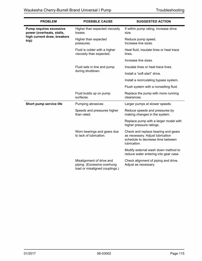
Waukesha Cherry-Burrell Brand Universal I Pump Troubleshooting
PROBLEM POSSIBLE CAUSE SUGGESTED ACTION
Pump requires excessive power (overheats, stalls, high current draw, breakers trip)
Higher than expected viscosity losses.
If within pump rating, increase drive size.
Higher than expected pressures.
Reduce pump speed. Increase line sizes.
Fluid is colder with a higher viscosity than expected.
Heat fluid, insulate lines or heat trace lines.
Increase line sizes.
Fluid sets in line and pump during shutdown.
Insulate lines or heat trace lines.
Install a “soft start” drive.
Install a recirculating bypass system.
Flush system with a nonsetting fluid.
Fluid builds up on pump surfaces.
Replace the pump with more running clearances.
Short pump service life Pumping abrasives Larger pumps at slower speeds.
Speeds and pressures higher than rated.
Reduce speeds and pressures by making changes in the system.
Replace pump with a larger model with higher pressure ratings.
Worn bearings and gears due to lack of lubrication.
Check and replace bearing and gears as necessary. Adjust lubrication schedule to decrease time between lubrication.
Modify external wash down method to reduce water entering into gear case.
Misalignment of drive and piping. (Excessive overhung load or misaligned couplings.)
Check alignment of piping and drive. Adjust as necessary.
01/2017 95-03002 Page 115

Maintenance Summary Reference Waukesha Cherry-Burrell Brand Universal I Pump
Page 116 95-03002 01/2017
Universal I Maintenance Summary Reference Sheet
Universal I Model
Change oil every 750 hours*ISO Grade 320, SAE 140 or AGMA Number 6EP
Grease bearings every 750 hours*NLGI Grade No. 2, EP, Lithium-based grease.
* Aggressive washdown or extreme running conditions may require more frequent lubrication intervals.
Oil Capacity (Gears) Grease Quantity (per Bearing)
Top or Bottom Side Mount Front Rear
006, 014, 015, 018, 024 1.3 oz (40 ml) 3.3 oz (100 ml) 0.37 oz (11 cc) 0.13 oz (4 cc)
030, 033A, 034, 040 2.0 oz (60 ml) 4 oz (120 ml) 0.60 oz (18 cc) 0.21 oz (6 cc)
060, 064, 130, 133A, 134 6.0 oz (170 ml) 9.5 oz (280 ml) 0.84 oz (25 cc) 0.76 oz (22 cc)
220, 223A, 224 11 oz (320 ml) 20 oz (600 ml) 1.33 oz (39 cc) 1.03 oz (30 cc)
320, 323A, 324 17 oz (500 ml) 44 oz (1300 ml) 1.96 oz (58 cc) 1.16 oz (34 cc)
Universal I Model
Rotor Type: Std & FF Hot Std & FF Hot Standard FF & Hot.0015 - .002 in .0015 - .002 in .001 - .004 in .0025 - .0055 in .004 - .006 .0055 - .0075 in
(.04 - .05 mm) (.04 - .05 mm) (.03 - .10 mm) (.06 - .14 mm) (.10 - .15 mm) (.14 - .19 mm)
.0015 - .002 in .0015 - .002 in .001 - .004 in .0025 - .0055 in .004 - .0065 in .006 - .0085 in
(.04 - .05 mm) (.04 - .05 mm) (.03 - .10 mm) (.06 - .14 mm) (.10 - .17 mm) (.15 - .22 mm)
.002 - .0025 in .002 - .0025 in .001 - .005 in .0025 - .006 in .0035 - .006 in .0065 - .009 in
(.05 - .06 mm) (.05 - .06 mm) (.03 - .13 mm) (.06 - .15 mm) (.09 - .15 mm) (.17 - .23 mm)
.003 - .0035 in .003 - .0035 in .003 - .0075 in .005 - .010 in .0045 - .009 in .0085 - .014 in
(.08 - .09 mm) (.08 - .09 mm) (.08 - .19 mm) (.13 - .25 mm) (.11 - .23 mm) (.22 - .36 mm)
.003 - .0035 in .003 - .0035 in .0035 - .0075 in .0055 - .0095 in .0045 - .009 in .009 - .015 in
(.08 - .09 mm) (.08 - .09 mm) (.09 - .19 mm) (.14 - .24 mm) (.11 - .23 mm) (.23 - .38 mm)
.004 - .005 in .004 - .005 in .0055 - .0095 in .009 - .013 in .005 - .010 in .010 - .015 in
(.10 - .13 mm) (.10 - .13 mm) (.14 - .24 mm) (.23 - .33 mm) (.13 - .25 mm) (.25 - .38 mm)
.005 - .006 in .005 - .006 in .008 - .012 in .010 - .014 in .007 - .012 in .013 - .018 in
(.13 - .15 mm) (.13 - .15 mm) (.20 - .30 mm) (.25 - .36 mm) (.18 - .30 mm) (.33 - .46 mm)PD100-598a
030, 033A, 034, 040
A - Back Facein (mm)
B - Rotor to Bodyin (mm)
C - Front Facein (mm)
006
014, 015, 018, 024
Standard Rotors: -40°F (-40°C) to 180°F (82°C); FF Clearance Rotors: 180°F (82°C) to 200°F (93°C); Hot Clearance Rotors: -40°F (-40°C) to 300°F (149°C). Contact SPX FLOW Application Engineering if alternate rotors are needed.
060, 064
133A, 130, 134
220, 223A, 224
320, 323A, 324
Std = Standard Clearance Rotors; FF = Front Face Clearance Rotors; Hot = Hot Clearance Rotors
Rotor Clearances
NOTE: The assembly clearances stated above are for reference only. Actual pump clearances may vary based on pump performance testing.
Universal I ModelWrench Size
Body Retaining Cap Screw
006, 014, 015, 018, 024, 030, 033A, 034, 040 3/16”
060, 064, 130, 133A, 134 1/4”
220, 223A, 224, 320, 323A, 324 5/16”

Waukesha Cherry-Burrell Brand Universal I Pump Maintenance Summary Reference
��
�
Universal I Maintenance Summary Reference Sheet - Copy for optional removalUniversal I Model
Change oil every 750 hours*ISO Grade 320, SAE 140 or AGMA Number 6EP
Grease bearings every 750 hours*NLGI Grade No. 2, EP, Lithium-based grease.
* Aggressive washdown or extreme running conditions may require more frequent lubrication intervals.
Oil Capacity (Gears) Grease Quantity (per Bearing)
Top or Bottom Side Mount Front Rear
006, 014, 015, 018, 024 1.3 oz (40 ml) 3.3 oz (100 ml) 0.37 oz (11 cc) 0.13 oz (4 cc)
030, 033A, 034, 040 2.0 oz (60 ml) 4 oz (120 ml) 0.60 oz (18 cc) 0.21 oz (6 cc)
060, 064, 130, 133A, 134
6.0 oz (170 ml) 9.5 oz (280 ml) 0.84 oz (25 cc) 0.76 oz (22 cc)
220, 223A, 224 11 oz (320 ml) 20 oz (600 ml) 1.33 oz (39 cc) 1.03 oz (30 cc)
320, 323A, 324 17 oz (500 ml) 44 oz (1300 ml) 1.96 oz (58 cc) 1.16 oz (34 cc)
Universal I Model
Rotor Type: Std & FF Hot Std & FF Hot Standard FF & Hot.0015 - .002 in .0015 - .002 in .001 - .004 in .0025 - .0055 in .004 - .006 .0055 - .0075 in
(.04 - .05 mm) (.04 - .05 mm) (.03 - .10 mm) (.06 - .14 mm) (.10 - .15 mm) (.14 - .19 mm)
.0015 - .002 in .0015 - .002 in .001 - .004 in .0025 - .0055 in .004 - .0065 in .006 - .0085 in
(.04 - .05 mm) (.04 - .05 mm) (.03 - .10 mm) (.06 - .14 mm) (.10 - .17 mm) (.15 - .22 mm)
.002 - .0025 in .002 - .0025 in .001 - .005 in .0025 - .006 in .0035 - .006 in .0065 - .009 in
(.05 - .06 mm) (.05 - .06 mm) (.03 - .13 mm) (.06 - .15 mm) (.09 - .15 mm) (.17 - .23 mm)
.003 - .0035 in .003 - .0035 in .003 - .0075 in .005 - .010 in .0045 - .009 in .0085 - .014 in
(.08 - .09 mm) (.08 - .09 mm) (.08 - .19 mm) (.13 - .25 mm) (.11 - .23 mm) (.22 - .36 mm)
.003 - .0035 in .003 - .0035 in .0035 - .0075 in .0055 - .0095 in .0045 - .009 in .009 - .015 in
(.08 - .09 mm) (.08 - .09 mm) (.09 - .19 mm) (.14 - .24 mm) (.11 - .23 mm) (.23 - .38 mm)
.004 - .005 in .004 - .005 in .0055 - .0095 in .009 - .013 in .005 - .010 in .010 - .015 in
(.10 - .13 mm) (.10 - .13 mm) (.14 - .24 mm) (.23 - .33 mm) (.13 - .25 mm) (.25 - .38 mm)
.005 - .006 in .005 - .006 in .008 - .012 in .010 - .014 in .007 - .012 in .013 - .018 in
(.13 - .15 mm) (.13 - .15 mm) (.20 - .30 mm) (.25 - .36 mm) (.18 - .30 mm) (.33 - .46 mm)PD100-598a
Standard Rotors: -40°F (-40°C) to 180°F (82°C); FF Clearance Rotors: 180°F (82°C) to 200°F (93°C); Hot Clearance Rotors: -40°F (-40°C) to 300°F (149°C). Contact SPX FLOW Application Engineering if alternate rotors are needed.
060, 064
133A, 130, 134
220, 223A, 224
320, 323A, 324
Std = Standard Clearance Rotors; FF = Front Face Clearance Rotors; Hot = Hot Clearance Rotors
030, 033A, 034, 040
A - Back Facein (mm)
B - Rotor to Bodyin (mm)
C - Front Facein (mm)
006
014, 015, 018, 024
Rotor Clearances
NOTE: The assembly clearances stated above are for reference only. Actual pump clearances may vary based on pump performance testing.
Universal I ModelWrench Size
Body Retaining Cap Screw
006, 014, 015, 018, 024, 030, 033A, 034, 040 3/16”
060, 064, 130, 133A, 134 1/4”
220, 223A, 224, 320, 323A, 324 5/16”
01/2017 95-03002 Page 117

Maintenance Summary Reference Waukesha Cherry-Burrell Brand Universal I Pump
��
�
Notes
Page 118 95-03002 01/2017


Universal I SeriesROTARY POSITIVE DISPLACEMENT PUMP
SPX FLOW, Inc.
611 Sugar Creek Road
Delavan, WI 53115
P: (262) 728-1900 or (800) 252-5200
F: (262) 728-4904 or (800) 252-5012
SPX FLOW, Inc. reserves the right to incorporate our latest design and material
changes without notice or obligation.
Design features, materials of construction and dimensional data, as described in
this bulletin, are provided for your information only and should not be relied upon
unless confirmed in writing.
Please contact your local sales representative for product availability in your
region. For more information visit www.spxflow.com.
The green “>” is a trademark of SPX FLOW, Inc.
ISSUED: 01/2017
COPYRIGHT © 2017 SPX FLOW, Inc.


![[MI 020-359] Universal Instruction Manual - I/A Series ...](https://static.fdocuments.in/doc/165x107/61e722ed89b0583af07e0425/mi-020-359-universal-instruction-manual-ia-series-.jpg)