UNIT V PART A: 1. direct axis and quadrature axis ...
35
UNIT V PART –A: 1. Synchronous machines with surface-mount magnets have very little difference between direct axis and quadrature axis inductances. Why? [April/May 2008] In synchronous machines with surface-mount magnets, as the magnets are on the rotor surface, and the shaft cross-section is circular, the sine wave motor is considered as a 'non-salient pole' synchronous machine. Hence there is very little difference between direct axis and quadrature axis inductance and they are considered as almost equal. 2. What is the magnitude of stator current in PMSM to achieve demagnetization? [April/May 2008 April/May 2010] q s E I Amps X = which is many times greater than the normal continuous rating of the motor winding (or) the converter. 3. What is meant by self control? [April/May 2010 Nov/Dec 2012 April 2017] As the rotor speed changes the armature supply frequency is also a change proportionally so that the armature field always moves at the same speed as the motor. The armature and rotor field move in synchronism for all operating points. Here accurate tracking of speed by frequency is realized with the help of rotor position sensor. 4. Define synchronous reactance in PMSM? [May/June 2013] It is the sum of armature leakage reactance and fictitious reactance. Xs = Xt + Xa 5. Draw the output phasor diagram of PMSM.[May/June 2013] 6. Write torque and EMF equation of PM synchronous motor. [Nov/Dec 2013] 11 s r l BB 3 T I 2 sin N m 2 2 = − ph m ph E 4.44f T volts = 7. Write the significance of power controllers of permanent magnet synchronous motors. [Nov/Dec 2013] The controller gets the signal from the rotor position sensor, reference speed signal and the signal from the output of power semiconductor circuit and then suitably turns on and off the concerned phase winding of SRM. 8. What is load commutation? [Nov/Dec 2009 April/May 2010 Nov/Dec 2012] Commutation of thyristors by induced voltages of load is known as "load commutation". Here frequency of operation is higher and, it does not require commutation circuits. Load commutation is
Transcript of UNIT V PART A: 1. direct axis and quadrature axis ...

UNIT V
PART –A:
1. Synchronous machines with surface-mount magnets have very little difference between
direct axis and quadrature axis inductances. Why? [April/May 2008]
In synchronous machines with surface-mount magnets, as the magnets are on the rotor surface,
and the shaft cross-section is circular, the sine wave motor is considered as a 'non-salient pole'
synchronous machine. Hence there is very little difference between direct axis and quadrature axis
inductance and they are considered as almost equal.
2. What is the magnitude of stator current in PMSM to achieve demagnetization? [April/May
2008 April/May 2010]
q
s
EI Amps
X=
which is many times greater than the normal continuous rating of the motor winding (or) the converter.
3. What is meant by self control? [April/May 2010 Nov/Dec 2012 April 2017]
As the rotor speed changes the armature supply frequency is also a change proportionally so that
the armature field always moves at the same speed as the motor. The armature and rotor field move in
synchronism for all operating points. Here accurate tracking of speed by frequency is realized with the
help of rotor position sensor.
4. Define synchronous reactance in PMSM? [May/June 2013]
It is the sum of armature leakage reactance and fictitious reactance.
Xs = Xt + Xa
5. Draw the output phasor diagram of PMSM.[May/June 2013]
6. Write torque and EMF equation of PM synchronous motor. [Nov/Dec 2013]
1 1 sr l BB3T I 2 sin N m
2 2
= −
ph m phE 4.44f T volts=
7. Write the significance of power controllers of permanent magnet synchronous motors.
[Nov/Dec 2013]
The controller gets the signal from the rotor position sensor, reference speed signal and the signal
from the output of power semiconductor circuit and then suitably turns on and off the concerned phase
winding of SRM.
8. What is load commutation? [Nov/Dec 2009 April/May 2010 Nov/Dec 2012]
Commutation of thyristors by induced voltages of load is known as "load commutation". Here
frequency of operation is higher and, it does not require commutation circuits. Load commutation is

ensured only at high speeds, whereas at low speeds the emf generated is not sufficient for load
commutation.
9. Briefly explain the vector control of PMSM. [Nov/Dec 2014]
The vector control technique is based on the reference frame transformation in which the armature
mmf axis and field axis are made to be in quadrature in all operating conditions.
10. Define the term load angle. [April/May 2015]
The angle between the no-load voltage and the excitation voltage is called as the load angle.
11. Write the drawbacks in PMSM. [April/May 2015]
Power factor of operation cannot be controlled as field winding cannot be controlled. It leads to
losses and decreases efficiency.
12. What are the features of PMSM?
1. Robust, compact and less weight.
2. No field current or rotor current
3. Copper loss.
4. High efficiency.
13. What are the advantages of load commutation?
1. It does not require commutation circuits.
2. Frequency of operation can be higher.
3. It can operate at power levels beyond the capability of forced commutation
14. What are the features of closed loop speed control of load commutated inverter fed
synchronous motor drive?
1. Higher Efficiency
2. Four quadrant operation with regeneration breaking is possible.
3. Higher power ratings and run at high speeds (6000rpm).
15. Why PMSM operating in self controlled load is known as commutator less dc motor.
Load side controller performs some what similar function as commutator in a dc machine. The
load side converter and synchronous motor combination functions similar to a dc machine. First, it is fed
from a dc supply and secondly like a dc machine. The stator and rotor field remain stationary with respect
to each other all speeds. Consequently, the drive consisting of load side converter and synchronous motor
is known as ‘commutator less dc motor’ .
16. What is pulsed mode?
For speeds below 10% of base speed, the commutation of load side converter thyristors is done by
forcing the current through the conducting thyristors to zero. This is realized by making source side
converter to work as inverter each time load side converter thyristors are to be turned off. Since the
frequency of operation of load side converter is very low compared to source frequency. Such an operation
can be realized. The operation of inverter is termed as pulsed mode.
17. Differentiate the synchronous reluctance motor and PMSM.
Synchronous Reluctance Motor
1. Rotor has no permanent magnet
2. Less cost
3. Low efficiency
PMSM
1. Rotor has permanent magnet
2. High cost
3. High efficiency,
18. How are PMBLDC motor and PMSM different?
PMBLDC Motor

1. Rectangular distribution of magnetic flux in the air gap.
2. Rectangular current waveform.
3. Concentrated stator winding.
PMSM Motor
1. Sinusoidal or quasi-sinusoidal distribution of magnetic flux in the air gap.
2. Sinusoidal or quasi-sinusoidal current waveforms.
3. Quasi-sinusoidal distribution of stator conductors.
19. State the two classifications of PMSM and the types in each.
1. Sinusoidal PMSM
2. Trapezoidal PMSM
20. Differentiate between self-control and vector control of PMSM.
Self-Control:
1. Dynamic performance is poor. 2. Control circuit is simple.
Vector Control:
1. Better performance. 2. Control circuit is complex.
21. What is brushless a.c. motor?
The sinusoidal current fed motor, which has distributed winding on the stator inducing sinusoidal
voltage is known as brush less a.c. motor. It is used in high power drives. The brushless a.c. motor is also
known as PMSM.
22. What are the types of PMSM?[Nov 2016]
1. General classification
(i) Surface mounted motor
(ii) Interior motor.
The surface mounted motor is further classified as: (i) Projected type. (ii) Insert type
2. Based on rotor classification. (i) Peripheral (ii) Interior (iii) Claw-pole (iv) Transverse
23. When does a PM synchronous motor operate as a synchronous reluctance motor.
If the cage winding is induced in the rotor and the magnets are left out or demagnetized, a PM
synchronous reluctance motor operates as a synchronous reluctance motor.
24. State the power controllers for PMSM.
1. PWM inverter using power MOSFETS with mciroprocessor control.
2. PWM inverter using BJT’s with microprocessor control (upto 100KW) .
25. Write the advantages of optical sensors.
1. Quite suitable for sinusoidal type motor as it is a high resolution sensor.
2. The signal from the photodiode rises and falls quite abruptly and the sensor outputs are switched high or
low so the switching points are well defined.
26. Write the disadvantages of optical sensors.
1. It requires a clean environment.
2. Provision of high resolution sensor adds the cost of the system.
27. Draw the torque-speed characteristics of PMSM. [Nov/Dec 2010]
28. Define synchronous reluctance. [Nov/Dec 2010]
The stator has a three phase symmetrical winding which creates a sinusoidal rotating magnetic
field in the air gap and the reluctance torque is developed because the induced magnetic field in the rotor
has a tendency to cause the rotor to align with the stator field at a minimum reluctance position and stator
rotates at synchronous speed.
29. Write the expressions for power input and torque of a permanent magnet synchronous
motor. [April/May 2011]
m
3EIsinT N m
= −
Power input = 3V I
( )q a s a3 E I Z I= +
( )2
q a a a3 E I I R= +
2
q a a a3E I 3I R= +
30. What are the types of power controllers used for permanent magnet synchronous motor?
[April/May 2011]
1. Fuzzy logic controllers.
2. PI controller.
31. What is the magnitude of stator current in PMSM to achieve demagnetization? [Nov/Dec
2009]
To achieve demagnetization, the magnitude of stator current is sinusoidal distribution and current
magnitude as well as torque reduces.
32. What are the merits and demerits of PMSM?[May/June 2007 Apr/May 2015]
Merits
i. It runs at constant speed.
ii. No field winding, no field loss, better efficiency.
iii. No sliding contacts. So it requires less maintenance.
Demerits
i. Power factor of operation cannot be controlled as field winding cannot be controlled.
ii. It leads to losses and decreases efficiency.
33. What is meant by self control? Nov/Dec-12 & Apr/May-10
As the rotor speed changes the armature supply frequency is also changes proportionally.So that the
armature field always moves at the same speed as the motor. The armature and Rotor field move in
synchronism for all operating points. Hence accurate tracking of speed.By frequency is realized with the
help of RPS.

34. State the advantages of PMSM. Apr/May-13
1. Improved performance
2. Reliability increases.
3. Reduced components
4. Versatility of the controller.
35. What are the applications of PMSM. [Apr/May 2010 Nov/Dec 2011 May/June 2014]
1. Used as direct drive traction motor
2. Used as high speed and high power drives for compressors, blowers,conveyors,fans.
36. What are assumptions made in derivation of emf equation for PMSM? (Nov/Dec-14)
Assumptions
1. Flux density distribution in the air gap is sinusoidal.
2. Rotor rotates with an uniform angular velocity of wm (r/sec).
3. Armature winding consists of full pitched, concentrated similarly located coils of equal number of
turns.
37. Why PMSM operating in self controlled mode is known commutator less dc
motor? Nov/Dec-13
Load side controller performs some what similar function as commutator in a dCmachine. The load side
converter and synchronous motor combination functions similarto a dc machine.
First, it is fed from a dc supply and secondly like a dc machine. The stator and rotor field remain stationary
with respect to each other at all speeds. Consequentlydrive consisting of load side converter and
synchronous motor is known as “Commutatorless dc motor”.
38. Write the emf equation of PMSM. (AU, Chennai/ME(PED)-May2008)
ph m wl phE 4.44f K T volts.=
This is the rms value of induced emf per phase. Where,
F – Frequency in hertz. Tph – Turns per phase
- Flux per pole. K – Winding factor.
39. Explain the vector control of PMSM. (Nov/Dec-14)
PMSM are employed for variable speed applications. The process of controlling voltage and
frequency to get the desired speed and torque is known as vector control of PMSM.
40.What are the types of magnets used in PM motors.[April 2017]
1.Alnico magnets
2.Cobalt-Samarium magnets
3.Barium and strontium ferrites.
4.Neodymium-Iron-Boron magnet

PART – B
1. Explain the construction and operation of PMSM. (16)[Nov/Dec-14& Nov/Dec-13]
(OR)
Enumerate the construction and performance of PMSM with suitable diagrams. [May/June 2007
April/May 2010 Nov/Dec 2014 April 2017]
(OR)
Discuss the different rotor configuration of PM synchronous machine. [Nov/Dec 2012]
CONSTRUCTIONAL FEATURES OF PERMANENT MAGNET SYNCHRONOUSMOTOR (OR)
IDEAL SINE WAVE BLPM DC MOTOR
Constructional wise, the BLPM sinewave motor is similar to that of BLPM square wave motor.
The armature windingand the shape of the permanent magnet areso designed that the flux
densitydistribution of the airgap is sinusoidal (i.e..)the magnetic field set up by the permanentmagnet in
the airgap is sinusoidal. Becauseof the presence of permanent magnet, inthis motor also, the slip rings and
fieldwindings are absent. The cross-section ofpermanent magnet synchronous motor isshown in the Fig.
Fig. Permanent magnet svnchronous motor
The PM synchronous motor has stator and rotor
Stator
The stator which is the stationary member, houses the armature winding. Bymaking continuous
strips of soft steel, the stator laminations for axial machines areformed. The thickness of the lamination
depends upon the frequency of the armaturesource voltage. The cost is also a major constraint for selection
of thickness. The yokeof the machine completes magnetic path.
A sinusoidal PMAC motor has distributed armature winding in the stator. Thearmature windings
are generally double layer and lap wound. The individual coils areconnected together to form phasor
groups. The phasor groups are connected togetherin series/parallel combinations to form star or delta
connections and two phase orsignal phase windings.
The coils, phase groups and the phase must be insulated from each other in theend-turn regions
and the required dielectric strength of the insulation will dependupon the voltage rating of the machine. In
permanent magnet machine, the airgapplays a major role as the airgap length largely determines the
operating point of thepermanent magnet in the no-load operating condition of the machine. Also
longerairgaps reduce machine windage losses.
Rotor
The rotor poles are so shaped that the voltage induced in a stator phase has a sinusoidal
waveform. As we know, the rotor is made up of permanent magnet.Usually ferrite magnets are employed.
Rare earth (cobalt-samarium) magnets,although expensive, are some times used to reduce the volume and
weight of themotor. Various types of permanent magnets have been already studied in previouschapter.
Many permanent magnet synchronous machines may be physically cylindrical butelectrically the
permanent magnet is equivalent to a salient pole structure. Actually,the permanent magnet poles are
inherently salient type. Some of the rotors ofpermanent magnet synchronous motor have the magnets
directly facing the airgap.
There are four types of rotor geometries in general. They are,

1. Peripheral 2. Interior
3. Claw-pole 4. Transverse
Peripheral type rotor
The peripheral type rotor of permanent magnet synchronous motor is shown in theFig. The
permanent magnets are located on the rotor periphery. The flux pattemof permanent magnet is radial.
Fig. Peripheral type rotor
Interior type rotor
In this type, the permanent magnets are located in the interior of the rotor as shown in the Fig. The
pattern of flux is generally radial.
Fig. Interior type rotor
Interior type rotors are more robust but not easier to construct compared to peripheral type. They
are suitable for high speed applications.
Claw-pole type rotor
The following Fig. shows the claw-pole type rotor configuration.

Fig. Claw-pole type rotor
The permanent magnets are generally disc-shaped and magnetized axially. The long, soft-
extensions of the construction comes out axially from the periphery of the discs like ‘Claws’ or Lundell
poles. Hence it is called as claw-pole type or Lundell type rotor. There is a set of equally-spaced alternate
claws on each disc forming alternate north and south poles.
Transverse type rotor
The permanent magnet in the rotorare generally between soft-iron poles andthe flux pattern is
circumferential. In thistype of rotor, the rectangles in the soft-iron poles indicate damper bars.
The Fig. shows the transverse typerotor configuration. As the permeabilityof the permanent magnet is very
low,magnetically, this configuration issimilar to a reluctance machine rotor. Hence, there exist both the
reluctancetorque as well as torque resulting fromthe flux of permanent magnet.
Fig. Transverse type rotor
2. Explain the principle of operation of a sine wave PM synchronous machine in detail. Draw its
phasor diagram and derive its torque equation. [Nov/Dec 2007 Nov/Dec 2013]
(Note: For phasor diagram and torque equation refer below questions)
For a common 3-phase PM synchronous motor, a standard 3-phase power stage is used. So, the
permanent magnet synchronous motor is fed directly from a three phase supply. When the armature
winding draws a current, the current distribution within the stator armature winding depends upon the
rotor position and the turning on process of the devices in the control circuit. The sinewave voltage output
is to be applied to the 3-phase winding system in such a way that angle between the stator flux and the
rotor flux is kept close to 90° to get the maximum generated torque. To meet this criterion, the motor
requires electronic control for proper operation.
The armature supply frequency (armature is in stator, permanent magnet at the rotor) is changed
in proportion to the rotor speed changes so that the stator field always moves at the same speed as the
rotor. The rotor position sensor is required for accurate tracking of the speed in order to prevent the motor
from pulling out of step and to avoid instability due to the change in torque or frequency. Sensors used
with the brushless a.c motor are expensive compared to those required with brushless d.c. motor. Because
of features like excellent dynamic performance and low torque ripple, the PMSM drive is widely used in

high performance servo drives in spite of its high cost. For starting the large synchronous motor, the
machine is operated in self-controlled mode.
3. Derive the EMF and Torque equation of PMSM. [Nov/Dec 2007 April/May 2010 May/June
2013 Nov/Dec 2013 Nov 2016 April 2017].
Derive the expression for torque developed in PMSM[April/May 2008 Nov/Dec 2012]
EMF Equation of BLPM Sinewave Motor
Now, let us determine the expression for the open-circuit phase emf due to the magnet. This emf
equation of the permanent magnet synchronous motor can be derived by considering the emf induced in
the elementary group of conductors. In the forthcoming derivation, the armature winding and shape of the
permanent magnet are so designated that the flux density distribution of the airgap is sinusoidal.
The fig. depicts an ideal sinewave brushless motor with pure sine-distributed phase winding and
permanent magnet rotor with sine-distributed flux.
Fig.Ideal brushless sine wave motor with pure sine-distributed phase winding and
permanent magnet rotor with sine-distributed flux.
As shown in the waveform of Fig., the magnetic field setup by the permanentmagnet in the airgap
is sinusoidal.
Flux density distribution
The flux density can be expressed as B = B sin p θ or B cos p θ or B sin (p θ α)or B cos (p +
α), where p = number of pole pairs depending upon the position of thereference axis
Fig. Flux density distribution
Now, consider a full pitched single turn armature coil as shown in the Fig.Letus rotor be revolving
with a uniform angular velocity ofmmec.rad/sec.
At time t = 0, let the axis of the single turn coil be along the polar axis.
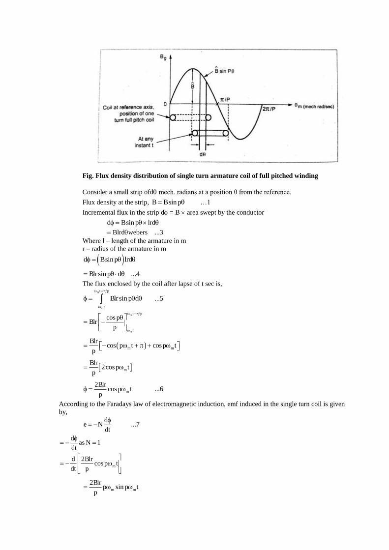
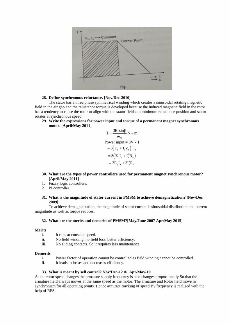
Fig. Flux density distribution of single turn armature coil of full pitched winding
Consider a small strip ofd mech. radians at a position θ from the reference.
Flux density at the strip, B Bsin p= …1
Incremental flux in the strip d = B area swept by the conductor
d Bsin p lrd =
Blrd webers ...3=
Where l – length of the armature in m
r – radius of the armature in m
( )d Bsin p lrd =
Blrsin p d ...4=
The flux enclosed by the coil after lapse of t sec is, m
m
t p
t
Blrsin p d ...5
+
=
m
m
t p
t
cos pBlr
p
+
= −
( )m m
Blrcos p t cosp t
p= − + +
m
Blr2cos p t
p=
m
2Blrcosp t ...6
p =
According to the Faradays law of electromagnetic induction, emf induced in the single turn coil is given
by,
d
e N ...7dt
= −
das N 1
dt
= − =
m
d 2Blrcos p t
dt p
= −
m m
2Blrp sin p t
p=

m me 2Blr sin p t ...8=
Let the armature winding be such that all turns of the phase are concentrated fullpitched and
located with respect to pole axis in the same manner.
Let Tph be the number of turns connected in series per phase. Then the algebraic addition of the
emfs of the individual turns gives the emf induced per phase as all the emfs are equal and in phase.
( )ph m m phe 2Blr sin p t T ...9=
m ph m2Blr T sin p t=
ph m m eE sin p t, wherep= =
ph eE sin t ...10=
Where e - Anular frequency in elec.rad/sec.
ph ph mE 2BrlT ...11=
Now, Eph= rms value of the phase emf
phE
2=
ph m2BrlT=
ph ph mE 2BrlT volts ...12 =
Where, e
m ...13p
=
We know that, m - sinusoidally distributed flux/pole.
= Bavl …14
= Bav2 r
l2p
..15
The average value of flux
density for sinewave
= 2
(normal value) =
2B
…16
The above equation is the practical emf equation of PMSM.
Hence, b1 p1 s1K 1; K 1; K 1
( )w1 p1 b1 s1K K K K 1 windingfactor=
Thus the rms value of per phase emf is expressed as,
ph m ph w1E 4.44f T K volts=
Torque Equation of an Ideal BLPM Sine wave motor
The emf equation of permanent magnet synchronous motor is studied in the previous section. Now, let us
derive the torque equation.
Let the armature ampere conductor distribution of ideal BLPM sine wave motor be given by,
A Asin P=
The flux density distribution set up by the rotor permanent magnet is also sinusoidal. Also, let us assume
that the axis of armature ampere conductor distribution be displaced from the axis of the flux density
distribution by an angle 2
−
as shown in Fig.
Now, B Bsin P2
= + −
( )Bsin P2
= + −
( )Bcos P= −
( )B Bcos P ...1= −
Fig. Ampere conductor and flux density distribution
Consider a small strip of width d at an angle from the reference axis.
Flux density at the strip ( )B Bcos P= −
Ampere conductors in the strip = Ad
= A sin P d …2
Force experienced by thed BlAd ...3
armature conductors in the strip
=
( )dF Bcos P l Asin P d ...4= −
( )dF ABlsin P cos P d= −
Let ‘r’ be the radial distance of the conductors from the axis of the shaft.
The torque experienced by the ampere conductors of the strip = dF r …5
( )dT ABrlsin P cos P d N m ...6= − −
Also, Torque experienced by the ampere conductors/pole
x P
0
T pole dT
=
=
= =
Hence, ( )p
0
T ABrlsin P cos P d ...7
= −
( )p
0
ABrlsin P P sin d
2
= + − +
( )p
0
cos 2PABrlsin
2 2P
− = − +
ABrl cos cossin
2 2P 2P p
= − + +
ABrlT sin N m ...8
2 p
= −
The total torque experience by all armature conductors,
2P torque pole=

ABrl2P sin ...9
p 2
=
T ABrlsin N m ...10= −
As the armature conductors are located in stator of the BLPM SNW motor, the rotor experiences an equal
and opposite torque.
The torque experienced by the rotor
= Torque developed by the rotor
ABrlsin= −
ABrlsin= − where = - …11
is known as power angle or torque angle.
T ABrlsin= is an ideal motor.
Now, consider the case of an armature winding which has three phases. Further the winding consists of
short chorded coils and the coils of a phase group are distributed.
This 3 armature winding carries a balanced 3a.c. current which are sinusoidally varying. The phase
windings are denoted as a, b, c.
The axes of phase winding are displaced by 2
3p
mechanical radians or
2
3
elec. radians. The current in the
winding are also balanced. An armature winding is said to be balanced, if all the three phase windings are
exactly identical in all respects but there axes are mutually displaced by 2
3p
mech. radians apart.
A three phase armature current is said to be balanced when the 3-phase currents are exactly equal but
mutually displaced in phase by 120°.
Let,
( )a m
b m
m
i I cos t i.e., 2Icos t
2 2I I cos t 2Icos t ...12
3 3
2 2ic I cos t 2Icos t
3 3
=
= − = −
= + = +
When the 3a.c current passes through the 3 balanced winding it sets up an armature mmf in the airgap.
The space distribution of the fundamental component of armature ampere conductors is given by,
a m
b m
c m
f F cos P
2f F cos P ...13
3
4f F cos P
3
=
= −
= −
Torque developed in a practical BLPM SNW motor
1. It is known that the ampere turn distribution of a phase winding consisting of full pitched coil is
rectangular of amplitude iTph. But the fundamental component of this distribution is 4/iTph
2. In a practical motor, the armature turns are short chorded and distributed. Further they may be
accommodated in skewed slots. In such a case for getting fundamental component of ampere turns
distribution, the turns per phase is modified as Kw1 Tph where Kw1 is winding factor which is equal to
Ks1 Kp1 Kd1.
Here, Ks1 = Skew factor
sin 2
; skew angle in elec. rad.2
= −
1
mK sin ; m coil span in elec. rad
2
= −
Kd = Distributor factor

sin q v 2
qsin v 2=
v = Slot angle in elec. rad
q = Slot per pole for 60° phase spread
w1 s1 p1 d1K K K K 1=
The fundamental component of ampere turns per phase of a practical case is written as,
ph w1
4iT K ...16=
3. when a balanced sinusoidally varying 3 phase a.c current passes through a balanced 3 phase winding it
can be shown that the total sinusoidally distributed ampere turns is equal to max w1 ph
3 4I K T
2
ph w1 ph
4 32I K T ...17
2=
4. The amplitude of the ampere conductor density distribution is shown as equal to the total sinusoidally
distributed ampere turns divided by2.
⸫ A in a practical 3 motor ph w1 ph
4 32I K T
2
2
= …18
Electromagnetic torque developed in a practical BLPM SNW motor
ABrlsin=
ph w1 ph
3 2I K T Brlsin
=
( )w1 ph ph3 2K T Brl I sin=
ph
ph
m
E3 I sin=
…19
4. Write about Self control of PMSM.
SELF CONTROL OF PERMANENT MAGNET SYNCHRONOUS MOTOR
Another method for controlling the speed of BLPM SNW motor is the self-control.
In this method, the speed of permanent-magnet synchronous motor is controlled byfeedingthem from
variable frequency voltage/currents. The rotor position sensors areemployed for operation in self-control
mode. Alternatively, induced voltage can beused to achieve self-control.
The schematic diagram of self-control is shown in the Fig.The mainadvantage of the self-control
is it ensures that for all operating points the armatureand rotor fields move exactly at the same speed. It is
expected that the armature androtor field move in synchronous for all operating points.
When there is a change in rotor speed, proportionally the armature supplyfrequency also changes
so that the armature field always moves at the same speed asthe rotor. With the help of rotor position
sensor, the accurate tracking of speedisrealized by the armature supply frequency.
In the Fig., when the rotor rotates into certain predetermined angle, the firingpulses to the
converter [rectifier-inverter] are varied. This firing of switches isproportional to the speed of motor. The
torque angle is varied electronically, so thereis an additional controllable parameter possessing greater
control of the motorperformance by changing the firing pulses to the semiconductor switches of
invertercircuit.

Fig.Self control of PASM motor
It is to be noted that at higher power levels, the current fed d.c. link converter isemployed. During
the commutation at low speed, the d.c. link current is pulsed byphase shifting the gate signal of the supply
side converter from rectification toinversion and back again.
When the current is zero, the motor side converter is switched on to a newconduction period and
supply side converter is then turned on. The time required forthe motor current to fall to zero can be
significantly shortened by placing a shuntthyristor in parallel with a d.c. link inductor. If the current zero is
needed; the lineside converter is phased back to inversion and the auxiliary thyristor is gated. The d.c.link
inductor is then short circuited and without affecting the motor, the current canbe supplied.
The auxiliary thyristor is immediately blocked when the line side converterturned on. This
method of motor current interruption reduces the effects of pulsatingtorque.
5. Discuss the various power controllers used in PMSM. [Apr/May 2015]
POWER CONTROLLERS (OR) CLOSED LOOP CONTROLLER
The schematic diagram of Fig. shows the power controller for PMSMdrive. The main functions
required are speed control and torque control.

Fig. Power controller for permanent magnet synchronous motor
The permanent magnet synchronous motor rotates due to the torque produced bytwo interacting
magnetic fields. On one hand, there is a magnetic field from the permanent magnets mounted in the rotor.
On the other hand, there is a magnetic fieldgenerated by the coils of the stator.
For a common 3-phase PM synchronous motor, a standard 3-phase power stage isused. So, the
permanent magnet synchronous motor is fed directly from a three phasesupply. When the armature
winding draws a current, the current distribution withinthe stator armature winding depends upon the rotor
position and the turning on process of the devices in the control circuit. The sinewave voltage output
isapplied to the 3-phase winding system in a way that angle between the stator fluxthe rotor flux is kept
close to 90° to get the maximum generated torque. To meet this criterion, the motor requires electronic
control for proper operation.
Thearmature supply frequency (armature is in stator, permanent magnet at therotor) is changed in
proportion to the changes in rotor speed so that the stator fieldalways moves at the same speed as the rotor.
The rotor position sensor is requiredfor accurate tracking of the speed in order to prevent the motor from
pulling out of stepand to avoid instability due to the change in torque or frequency.
The torque is related with the d-axis & q-axis currents. In order to achieve the maximum
torque/current ratio the d-axis current is set to zero during the constant torquecontrol so that the torque is
proportional only to the q-axis current. Therefore,this results in the control of q-axis current for regulating
the torque in rotor referenceframe. The total drive system looks similar to that of BLDC motor and
consists ofPMSM, power electronic devices, converter, sensors & controller.
With sinusoidally excited stator, the rotor design of the PMSM becomes moreflexible than the
BLDC motor. If the motor windings are star connected without aneutral connection, 3-phase currents can
flow through the inverter at any moment.
The PWMcurrent control isstill used to regulate the actual machine current.Either a hysteresis
current controller, a PI controller with sinusoidal triangle or an SVPWM strategy is employed for this
purpose. Unlike the BLDC motor, the 3switches are switched at any time.
6. Explain in detail the vector control of permanent magnet synchronous motor.
[Nov/Dec 2012]
VECTOR CONTROL OF BLPM SNW MOTOR
As we know, the permanent magnet synchronous [BLPM SNW] motor has permanent magnets in
rotor instead of a field winding. Hence, the field control is notpossible. So, in vector control.v/f ratio is
kept constant so that both v, f are varied toget the desired speed and torque. Now, let us consider the two
cases of followingFig. whose armature conductor currents and airgap flux are shown. In theFig.(a) the flux
axis is in quadrature with the armature mmf axis. Each and everyconductor experiences a force which
produces the torque. This torque contributed byvarious armature conductors have the same direction
though there is a presence ofvariation in magnitude.
Fig. (a) Quadrature position of airgapflux and armature mmfaxis Fig.(b) Non-quadrature
position of airgap fluxand armature mmf axis

Now, consider a case in which the angle between the axis of the airgap flux andthe armature mmf
axis is 90° elect. and the armature conductor current distributionand airgap flux distribution are as shown
in Fig. (b). In this case also, a torque isexperienced but the directions of the torque experienced by the
conductors is not thesame. Consequently, the resultant torque gets reduced. It is realized that both
thesteady state and dynamic performance of the machine in the case (b) is poorer thanthe case (a).
It is understood that the armature mmf axis and the axis of permanent magnet areshould be in
quadrature for permanent magnet synchronous motor during alloperating conditions in order to have better
steady state and dynamic performance.
The schematic diagram for vector control is shown in Fig.As the speed isvaried from a low value
upto the corner frequency, the desired operating point ofcurrent is such that Id = 0 and the current is along
the q-axis.
Fig. Vector control of PMSM motor
This condition can be obtained by controlling the voltage by PWM technique afteradjusting the
frequency to a desired value. If the frequency is more than the cornerfrequency, it is impossible to make Id
= 0 because of voltage constraints. During suchconditions, after satisfying the voltage constraints a better
operating point for currentcan be obtained with minimum value of Id.
It is possible to set the values of Id(ref) and Iq(ref) for the required dynamic andsteady state
performance by knowing the desired values of torque, speed and thevoltage to which the motor is
subjected to. These reference values of Id and Iq aretransformed into reference values of currents such as
ia(ref), ib(ref), ic(ref). These phasecurrents are compared with the actual currents and the error values actuate
thetriggering circuitry which is also controlled by the signals obtained from rotorposition sensor and speed
signal. To control the torque and speed independently, thereis a need to control the magnitude and phase of
the three currents ia, ib, ic through afast inverter. This is accomplished by the power electronic switching
circuitry.
7.Explain the speed-torque characteristics of permanent magnet synchronous motor.
[April/May 2008 Nov/Dec 2014 Nov 2016]
TORQUE - SPEED CHARACTERISTICS OF PERMANENT MAGNETSYNCHRONOUS
MOTOR

The phasor diagram of permanent magnet synchronous motor has been studied insection It was
alsothestudied that the direct axis current sets up mmf alongaxis of the permanent magnet and the
quadrature axis current sets up mmf along theaxis perpendicular to the permanent magnet axis. The phasor
diagram and associatedvoltage equations are used to derive the control laws and predict the performance
ofthe permanent magnet synchronous motor in closed analytical form.
At a given speed, Eq is fixed by the magnetic flux [where Eq is the back emf] andthe torque is
proportional to the speed. This relationship is valid even at zero speed. The linear relationship between
torque and current is an important feature. Itsimplifies the controller design and makes the dynamic
performance more regular andpredictable.
When the speed and frequency increase, the current limit locus remains fixed butthere comes a
speed at which the radius of the voltage-limit locus begins to decrease.If PWM control is employed in the
system under consideration, the PWM duty cyclereaches the maximum at the above said speed and the
PWM control is sometimes saidto have saturated at this point. When the current reaches the rated value
(IC), theoperation along the quadrature axis is possible. The speed at which it happens iscalled the 'corner-
point' speed. It is the maximum speed at which, rated torque can bedeveloped.
If the speed increases further, the radius of the voltage limit locus decreases.This decreasing
radius of the voltage limit circle 'drags' the maximum currentphasor further and further ahead of the q-axis,
consequently q-axis current decreasesand the d-axis current increases in negative or demagnetizing
direction.
The above condition can be continued upto a stage (say point M) at which speed,the maximum
current(Ic) can still be forced into the motor entirely in the d-axis. It isto be noted that no torque is
developed as torque is proportional to the q-axis current.
If the speed is increased beyond the above said point M, there is a risk of overcurrent because the
back emfEq continues to increase while the terminal voltageremains constant. The current is then almost a
pure reactive current flowing from themotor back to the supply. There is a small q-axis current and a small
torque becauseof losses in the motor and in the converter. The power flow is thusreversed.
This mode of operation is possible only if the motor 'over runs' the converter or isdriven by an
external load or prime mover. The reactive current is limited only by the synchronous reactance. As the
speedincreases, it approaches the short circuit current,which may be many times larger than the normal
current rating of the motor windings or the converter. This current may be sufficient to demagnetize the
magnets particularly if their temperature is high.
Torque Speed Characteristics of PMSM
For a given maximum permissible voltage (Vc) and maximum permissible current (Ic), the
maximum torque remains constant from a low frequency to corner frequency. Any further increase in
frequency decreased the maximum torque. The shaded portion in the torque-speed characteristics
represents the permissible region of operation in torque speed characterisics.
8. Write short notes on
i. Volt-ampere requirements in PMSM [May/June 2013]
CONVERTER VOLT-AMPERE REQUIREMENTS
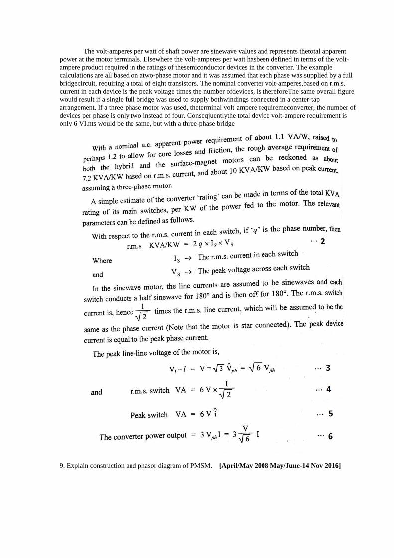
The volt-amperes per watt of shaft power are sinewave values and represents thetotal apparent
power at the motor terminals. Elsewhere the volt-amperes per watt hasbeen defined in terms of the volt-
ampere product required in the ratings of thesemiconductor devices in the converter. The example
calculations are all based on atwo-phase motor and it was assumed that each phase was supplied by a full
bridgecircuit, requiring a total of eight transistors. The nominal converter volt-amperes,based on r.m.s.
current in each device is the peak voltage times the number ofdevices, is thereforeThe same overall figure
would result if a single full bridge was used to supply bothwindings connected in a center-tap
arrangement. If a three-phase motor was used, theterminal volt-ampere requiremeconverter, the number of
devices per phase is only two instead of four. Conseqjuentlythe total device volt-ampere requirement is
only 6 VI.nts would be the same, but with a three-phase bridge
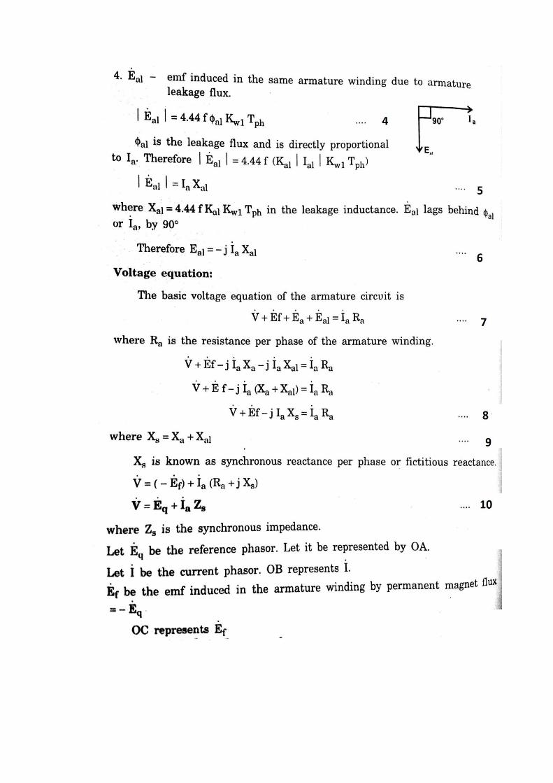
9. Explain construction and phasor diagram of PMSM. [April/May 2008 May/June-14 Nov 2016]


10. Discuss the
i. Armature reaction in PMSM[April/May 2015]


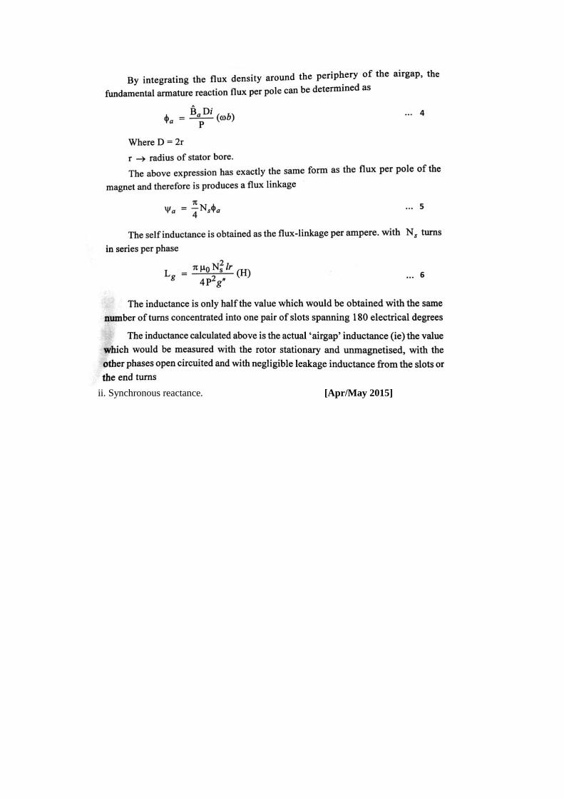
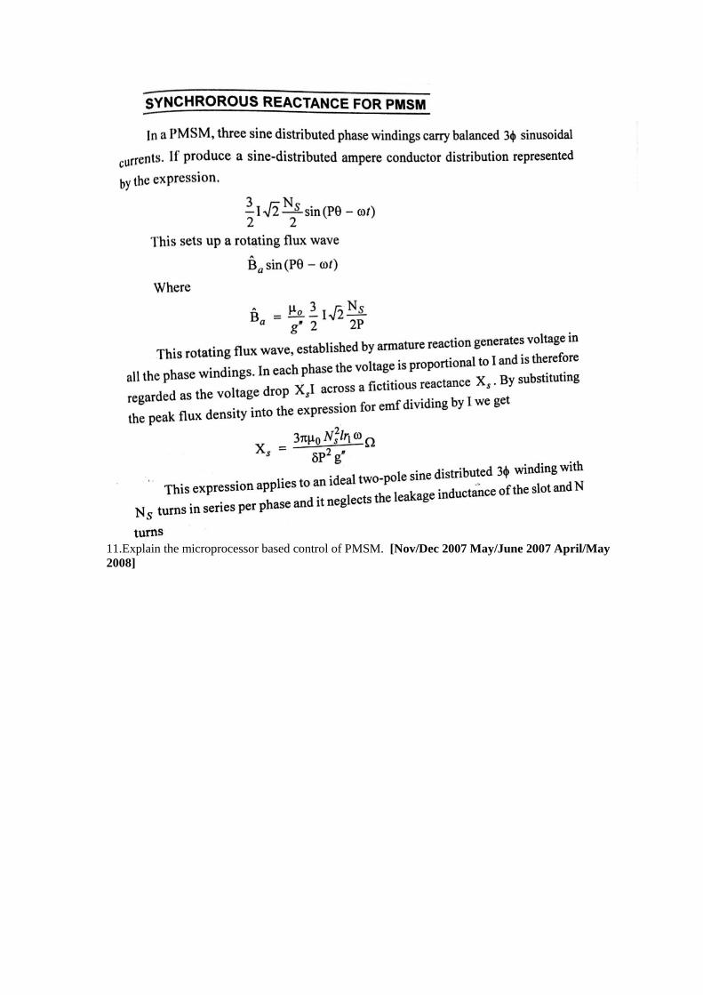
ii. Synchronous reactance. [Apr/May 2015]
11.Explain the microprocessor based control of PMSM. [Nov/Dec 2007 May/June 2007 April/May
2008]