UNIT INFORMATION M2 BACnet Module
38
Page 1 ©2014 Lennox Industries Inc. UNIT INFORMATION Corp. 0926-L11 10/2014 (Supersedes4/2014) M2 BACnet ® Module Service Literature Table of Contents General 1 ...................................... M2 BACnet Module Specifications/Default Settings 1 Cabling Guidelines 2 ............................ Network Bus Termination 2 ....................... M2 BACnet Module Installation 2 .................. Lennox BACnet Topology 3 ...................... General BACnet MS/TP guidelines 3 .............. Lennox Control Requirements 3 .................. Prodigy Control Mode Options 3 .................. Backup Sensor Modes 3 ......................... Control Mode Descriptions 5 ..................... Troubleshooting 6 ............................... Communication Check Out Table 6 ................ Device Objects and Property Ranges 6 ............ Lennox Proprietary Objects 7 ..................... Compressor (136) 8 ......................... Blower Object (129) 8 ........................ Heating Object (130) 9 ....................... Economizer Object (131) 10 ................... Discharge Air Object (133) 10 .................. Space Air Object (133) 11 ..................... Outdoor Air Object (133) 11 .................... Analog Output Objects 11 ......................... Analog Input Objects 12 .......................... Analog Value Objects 14 .......................... Zone Sensor Setpoints 14 ......................... M2 Alarm Codes 15 .............................. Application Details 16 ............................ Appendix A. Timeline of M2 startup sequence 34 ..... Appendix B. Supply Airflow Targets 35 .............. Appendix C. Effective Occupancy 36 ............... BACnet ® PIC Statement 38 ....................... General This document is provided to assist in the integration of the prodigy controller to the building automation system. This BACnet module does not require any Lennox proprietary software or interface in order for the BACnet module to function with the prodigy control system. The M2 BACnet ® Module (BM2) allows communication between the Lennox M2 Unit Controller and a BACnet ® MS/TP network. This module is mounted directly to the M2 Unit Controller board. The M2 BACnet ® Module has been developed to communicate with building automation systems that support the BACnet Application Specific Controller (B-ASC) device profile. M2 BACnet ® module is certified to ANSI/ASHRAE 135-2008 and is BTL Listed. Table 1. M2 BACnet ® Module Specifications and Default Settings Environment Operating temperature range -40F to 155F Storage temperature range -40F to 185F RH 10-95% RH non-condensing Field Connections BACnet ® MS/TP See PIC statement on Page 38. Transceiver RS-485 Connector Three-position terminal block ( + G – ) Baud Rate Selectable 9.6, 19.2, 38.4, 76.8K Cable Type Twisted pair w/shield, 22AWG min. Belden type 88761 or 8761. Len- nox 27M19, 94L63 or 68M25 Max. Cable Length 4000 ft. repeater is required for longer lengths. Bus Termination 120 ohm resistor on last module in chain. Default Values device Max_Master 127 device Max_Info_Frames 1 device Object_Identifier MAC address device Object_Name “Lennox_M2_" + MAC address device Location “US" device Description “Lennox HVAC Controller" baud rate 38.4k recommended update rate 2 minutes (before software v7.08) at least once every 12 minutes (software v7.08 and later) communication time-out 5 minutes (before software v7.08) 15 minutes (software v7.08 and later)
Transcript of UNIT INFORMATION M2 BACnet Module

Page 1 ©2014 Lennox Industries Inc.
UNIT INFORMATIONCorp. 0926-L1110/2014 (Supersedes4/2014)
M2 BACnet®
Module
Service Literature
Table of ContentsGeneral 1. . . . . . . . . . . . . . . . . . . . . . . . . . . . . . . . . . . . . .M2 BACnet Module Specifications/Default Settings 1Cabling Guidelines 2. . . . . . . . . . . . . . . . . . . . . . . . . . . .Network Bus Termination 2. . . . . . . . . . . . . . . . . . . . . . .M2 BACnet Module Installation 2. . . . . . . . . . . . . . . . . .Lennox BACnet Topology 3. . . . . . . . . . . . . . . . . . . . . .General BACnet MS/TP guidelines 3. . . . . . . . . . . . . .Lennox Control Requirements 3. . . . . . . . . . . . . . . . . .Prodigy Control Mode Options 3. . . . . . . . . . . . . . . . . .Backup Sensor Modes 3. . . . . . . . . . . . . . . . . . . . . . . . .Control Mode Descriptions 5. . . . . . . . . . . . . . . . . . . . .Troubleshooting 6. . . . . . . . . . . . . . . . . . . . . . . . . . . . . . .Communication Check Out Table 6. . . . . . . . . . . . . . . .Device Objects and Property Ranges 6. . . . . . . . . . . .Lennox Proprietary Objects 7. . . . . . . . . . . . . . . . . . . . .
Compressor (136) 8. . . . . . . . . . . . . . . . . . . . . . . . .Blower Object (129) 8. . . . . . . . . . . . . . . . . . . . . . . .Heating Object (130) 9. . . . . . . . . . . . . . . . . . . . . . .Economizer Object (131) 10. . . . . . . . . . . . . . . . . . .Discharge Air Object (133) 10. . . . . . . . . . . . . . . . . .Space Air Object (133) 11. . . . . . . . . . . . . . . . . . . . .Outdoor Air Object (133) 11. . . . . . . . . . . . . . . . . . . .
Analog Output Objects 11. . . . . . . . . . . . . . . . . . . . . . . . .Analog Input Objects 12. . . . . . . . . . . . . . . . . . . . . . . . . .Analog Value Objects 14. . . . . . . . . . . . . . . . . . . . . . . . . .Zone Sensor Setpoints 14. . . . . . . . . . . . . . . . . . . . . . . . .M2 Alarm Codes 15. . . . . . . . . . . . . . . . . . . . . . . . . . . . . .Application Details 16. . . . . . . . . . . . . . . . . . . . . . . . . . . .Appendix A. Timeline of M2 startup sequence 34. . . . .Appendix B. Supply Airflow Targets 35. . . . . . . . . . . . . .Appendix C. Effective Occupancy 36. . . . . . . . . . . . . . .BACnet® PIC Statement 38. . . . . . . . . . . . . . . . . . . . . . .
General
This document is provided to assist in the integration of theprodigy controller to the building automation system.
This BACnet module does not require any Lennoxproprietary software or interface in order for the BACnetmodule to function with the prodigy control system.
The M2 BACnet® Module (BM2) allows communication
between the Lennox M2 Unit Controller and a BACnet®
MS/TP network. This module is mounted directly to the M2
Unit Controller board.
The M2 BACnet® Module has been developed to
communicate with building automation systems that
support the BACnet Application Specific Controller
(B-ASC) device profile.
M2 BACnet® module is certified to ANSI/ASHRAE135-2008 and is BTL Listed.
Table 1. M2 BACnet® Module Specifications andDefault Settings
Environment
Operating temperaturerange
-40F to 155F
Storage temperature range -40F to 185F
RH 10-95% RH non-condensing
Field Connections
BACnet® MS/TP See PIC statement on Page 38.
Transceiver RS-485
Connector Three-position terminal block ( +G – )
Baud Rate Selectable 9.6, 19.2, 38.4, 76.8K
Cable Type Twisted pair w/shield, 22AWG min.Belden type 88761 or 8761. Lennox 27M19, 94L63 or 68M25
Max. Cable Length 4000 ft. repeater is required forlonger lengths.
Bus Termination 120 ohm resistor on last module inchain.
Default Values
device Max_Master 127
device Max_Info_Frames 1
device Object_Identifier MAC address
device Object_Name “Lennox_M2_" + MAC address
device Location “US"
device Description “Lennox HVAC Controller"
baud rate 38.4k
recommended update rate 2 minutes (before software v7.08)at least once every 12 minutes(software v7.08 and later)
communication time-out 5 minutes (before software v7.08)15 minutes (software v7.08 andlater)
Page 2Corp. 0926-L11 11/11
Cabling Guidelines
The M2 BACnet® Module is compatible with MS/TPEIA-485 daisy-chain networks communicating at 9.6, 19.2,38.4, and 76.8 kbps. Connect the BACnet® MS/TPnetwork cable to the M2 BACnet® module. It is compatiblewith twisted pair, shielded 22AWG minimum cable such asBelden 8761, 88761 and Lennox catalog numbers 27M19,94L63 or 68M25. A maximum of 32 M2 BACnet® modulescan be included per network segment. Up to 127 units canbe connected per network segment by using repeater forevery 32 devices.
The network cable should be routed using best practices toavoid induced noise. Do not route alongside high voltagewiring or in proximity to high-voltage or high-frequencydevices, such as ignition controls and variable frequencydrives. The BACnet MS/TP recommended maximum totalbus length (without repeater) is 4000 ft. (1219m) applies tothis device.
Network Bus Termination
When the M2 BACnet® Module is at the end of a daisychain, connect a 120 ohm resister across the '+' and '-'terminals. Every BACnet® MS/TP chain should have atermination at each end of the chain (exactly twoterminations; see Lennox BACnet Topology on next page).
IMPORTANTA qualified systems integrator with adequate training and experience is required to integrate and commission the M2 BACnet Module into a third partyBACnet building automation system. A BACnet configuration software tool is required to commissionthe BACnet network.
M2 BACnet Module Installation
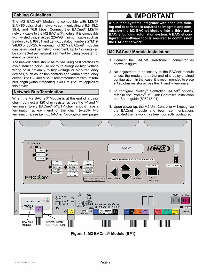
1. Connect the BACnet SmartWire� connector asshown in figure 1.
2. No adjustment is necessary to the BACnet moduleunless the module is at the end of a daisy-chainedconfiguration. In that case, it is recommended to placea 120 ohm resistor across the '+' and '-' terminals.
3. To configure Prodigy® Controller BACnet® options,refer to the Prodigy® M2 Unit Controller Installationand Setup guide (506215-01).
4. Upon power up, the M2 Unit Controller will recognizethe BACnet module and begin communicationsprovided the network has been correctly configured.
BACNETMODULE
SMARTWIRE�CONNECTION
Figure 1. M2 BACnet® Module (BP1)
Page 3 M2 BACnet® Module
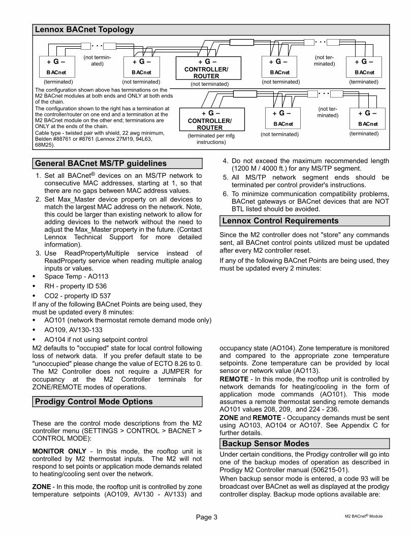
Lennox BACnet Topology
(terminated)(terminated) (not terminated) (not terminated)
CONTROLLER/ROUTER
(not terminated)
(not terminated)
(not terminated)
(terminated)(not terminated)(terminated per mfginstructions)
The configuration shown above has terminations on theM2 BACnet modules at both ends and ONLY at both endsof the chain.
The configuration shown to the right has a termination atthe controller/router on one end and a termination at theM2 BACnet module on the other end; terminations areONLY at the ends of the chain.
Cable type - twisted pair with shield, 22 awg minimum,Belden #88761 or #8761 (Lennox 27M19, 94L63,68M25).
CONTROLLER/ROUTER
(not terminated)
General BACnet MS/TP guidelines
1. Set all BACnet® devices on an MS/TP network toconsecutive MAC addresses, starting at 1, so thatthere are no gaps between MAC address values.
2. Set Max_Master device property on all devices tomatch the largest MAC address on the network. Note,this could be larger than existing network to allow foradding devices to the network without the need toadjust the Max_Master property in the future. (ContactLennox Technical Support for more detailedinformation).
3. Use ReadPropertyMultiple service instead ofReadProperty service when reading multiple analoginputs or values.
4. Do not exceed the maximum recommended length(1200 M / 4000 ft.) for any MS/TP segment.
5. All MS/TP network segment ends should beterminated per control provider's instructions.
6. To minimize communication compatibility problems,BACnet gateways or BACnet devices that are NOTBTL listed should be avoided.
Lennox Control Requirements
Since the M2 controller does not "store" any commandssent, all BACnet control points utilized must be updatedafter every M2 controller reset.
If any of the following BACnet Points are being used, theymust be updated every 2 minutes:
� Space Temp - AO113
� RH - property ID 536
� CO2 - property ID 537
If any of the following BACnet Points are being used, theymust be updated every 8 minutes:� AO101 (network thermostat remote demand mode only)
� AO109, AV130-133
� AO104 if not using setpoint control
M2 defaults to "occupied" state for local control followingloss of network data. If you prefer default state to be"unoccupied" please change the value of ECTO 8.26 to 0.The M2 Controller does not require a JUMPER foroccupancy at the M2 Controller terminals forZONE/REMOTE modes of operations.
Prodigy Control Mode Options
These are the control mode descriptions from the M2controller menu (SETTINGS > CONTROL > BACNET >CONTROL MODE):
MONITOR ONLY - In this mode, the rooftop unit iscontrolled by M2 thermostat inputs. The M2 will notrespond to set points or application mode demands relatedto heating/cooling sent over the network.
ZONE - In this mode, the rooftop unit is controlled by zonetemperature setpoints (AO109, AV130 - AV133) and
occupancy state (AO104). Zone temperature is monitoredand compared to the appropriate zone temperaturesetpoints. Zone temperature can be provided by localsensor or network value (AO113).
REMOTE - In this mode, the rooftop unit is controlled bynetwork demands for heating/cooling in the form ofapplication mode commands (AO101). This modeassumes a remote thermostat sending remote demandsAO101 values 208, 209, and 224 - 236.
ZONE and REMOTE - Occupancy demands must be sentusing AO103, AO104 or AO107. See Appendix C forfurther details.
Backup Sensor Modes
Under certain conditions, the Prodigy controller will go intoone of the backup modes of operation as described inProdigy M2 Controller manual (506215-01).
When backup sensor mode is entered, a code 93 will bebroadcast over BACnet as well as displayed at the prodigycontroller display. Backup mode options available are:

Page 4Corp. 0926-L11 11/11
� RAT: (Return Air Temperature) sensor located on all prodigy controlled equipment is the secondary sensor resource
� TSTAT: (Thermostat) inputs are the secondary sensor input source - requires equipment reset in order to recover onceprimary sensor data is corrected.
� NONE: Unit Idle / Off
Page 5 M2 BACnet® Module
Control Mode Descriptions
Select control modes via menu options: SETTINGS > CONTROL > BACNET > ... > CONTROL MODE > ZONE
LENNOX ZONE SENSOR CONTROLECTO values are expected to be as follows:� ECTO 6.01 option range 1-3
(M2 Menu selection: CONTROL MODE > ZONE)
� ECTO 5.27 equal to 0(M2 Menu selection: NETWORK SENSOR > TEMP > NO)
Lennox Zone Sensor must be installed and wired to the M2SENSOR inputs (see Figure 1). M2 may be controlledusing BACnet commands AO109 or AV130-133.
Lennox zone sensor must be installed and wired to M2sensor inputs. After power up, the rooftop unit (RTU) will bein IDLE mode for up to 2 minutes (specified by ECTO 5.25,defaults to 2 minutes), unless set points are sent overBACnet.
Controller sequence:
1. Setpoints not sent: Lennox zone sensor must beinstalled and wired to M2 sensor inputs. After powerup, RTU will be in IDLE mode for up to 2 minutes(specified by ECTO 5.25, defaults to 2 minutes),unless set points are sent over BACnet. RTU will
switch over to Zone sensor mode operation specifiedin ECTO 6.01. Base on ECTO 8.26(Unit_Run_Options), M2 will utilize specifiedtemperature setpoints and zone sensor data fornormal operation. M2 will switch over to Zone sensorbackup mode operation if there is no Lennox zonetemperature input.
2. Set points are sent over BACnet before 2 minutesstartup delay: RTU will operate based on these setpoints and the temperature read from the Lennox zonesensor. In the event of a subsequent networkcommunication failure (no application level BACnetpackets for 15 minutes), RTU will reset.
NETWORK ZONE SENSOR CONTROLECTO values are expected to be as follows:
� ECTO 6.01 option range 1-3 (CONTROL MODE > ZONE)
� ECTO 5.27 equal to 2. (Other sensor data options are available. Please refer to Insert reference to M2 manualdocument)
Controller sequence:
1. Network sensor data not sent: Lennox zone sensormust be installed and wired to M2 sensor inputs. Afterpower up, RTU will be in IDLE mode for up to 5 minutesawaiting network sensor data (Alarm 110 WAITINGFOR NETWORK SENSOR DATA). After 5 minutes,M2 will enter backup sensor mode of operationdisplaying Alarm 93. M2 will utilize specifiedtemperature setpoints and available sensor data fornormal operation.
2. Network sensor data are sent over BACnet before 5minute delay: RTU will operate based on specified setpoints and the network sensor data. In the event of asubsequent network communication failure (nonetwork sensor data for 5 minutes), RTU will displayAlarm 73 (NETWORK SENSOR ERROR). If and whenall the BACnet network sensor inputs are received,Alarm 73 will be removed.
NETWORK REMOTE THERMOSTAT CONTROLECTO values are expected to be as follows:
� ECTO 6.01 range 4-7 (CONTROL MODE > ZONE)
� ECTO 5.27 equal to 0 (NETWORK SENSOR > TEMP > NO)
Controller sequence:
1. Network demands not sent: After power up, RTU willbe in IDLE mode for up to 5 minutes awaiting networkdemand data (AO101 range 208, 209, 224 – 236).After 5 minutes, M2 will enter backup sensor mode ofoperation displaying “Alarm 93 BACKUP MODE" andalso broadcast Alarm 93 over BACnet. M2 will utilizespecified temperature setpoints and available sensordata for backup mode operation.
2. Network demands are sent over BACnet before 5minute delay: RTU will operate based on thesenetwork demands. In the event of a subsequentnetwork communication failure (no BACnet networkdemand packets for 15 minutes), RTU will switch overto Remote Demand backup mode operation specifiedin ECTO 6.01 and the RTU will display “Alarm 93BACKUP MODE".
Page 6Corp. 0926-L11 11/11
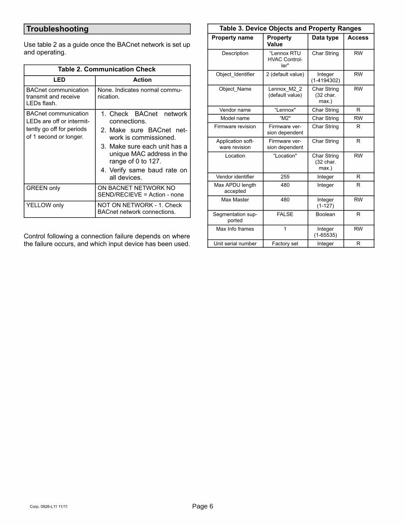
Troubleshooting
Use table 2 as a guide once the BACnet network is set upand operating.
Table 2. Communication Check
LED Action
BACnet communicationtransmit and receiveLEDs flash.
None. Indicates normal communication.
BACnet communication
LEDs are off or intermit
tently go off for periods
of 1 second or longer.
1. Check BACnet networkconnections.
2. Make sure BACnet network is commissioned.
3. Make sure each unit has aunique MAC address in therange of 0 to 127.
4. Verify same baud rate onall devices.
GREEN only ON BACNET NETWORK NOSEND/RECIEVE = Action - none
YELLOW only NOT ON NETWORK - 1. CheckBACnet network connections.
Control following a connection failure depends on wherethe failure occurs, and which input device has been used.
Table 3. Device Objects and Property Ranges
Property name PropertyValue
Data type Access
Description “Lennox RTUHVAC Control
ler"
Char String RW
Object_Identifier 2 (default value) Integer(1-4194302)
RW
Object_Name Lennox_M2_2(default value)
Char String(32 char.
max.)
RW
Vendor name “Lennox" Char String R
Model name “M2" Char String RW
Firmware revision Firmware version dependent
Char String R
Application software revision
Firmware version dependent
Char String R
Location “Location" Char String(32 char.
max.)
RW
Vendor identifier 255 Integer R
Max APDU lengthaccepted
480 Integer R
Max Master 480 Integer(1-127)
RW
Segmentation supported
FALSE Boolean R
Max Info frames 1 Integer(1-65535)
RW
Unit serial number Factory set Integer R

Page 7 M2 BACnet® Module
Lennox Proprietary Objects Device Objects
Property Description
CC
om
pre
sso
r
Heati
ng
Blo
wer
Eco
no
miz
er
Sp
ace
Air
Dis
ch
arg
e A
ir
Ou
tdo
or
Air
Object_Identifier Object_Identifier is a Read Only (RO) property, used to identify the Object and it is unique within Lennox BACnet Device.
� � � � � � �
Object_Name Object_Name is a Read Only (RO) property use to name the Object and is unique within theBACnet Device. The minimum length of the string is one character.
� � � � � � �
Object_Type Object_Type is a Read Only (RO) property and is one of the following: OBJECT_LNX_COMPRESSOR, OBJECT_LNX_HEATING, OBJECT_LNX_BLOWER,OBJECT_LNX_ECONOMIZER, OBJECT_LNX_INDOOR_AIR,OBJECT_LNX_DISCHARGE_AIR, OBJECT_LNX_OUDOOR_AIR.
� � � � � � �
Out_Of_Service Out_Of_Service is a Read Only (RO) property that indicates whether the physical componentthat the object represents is in service or not.
� � � �
Lennox_Object_Installed Lennox_Object_Installed is a Read Only (RO) property that indicates whether the physicalcomponent that the object represents is installed in the RTU or not. Unless the value of thisproperty is TRUE, all other properties of the Compressor, Heat Stage, or Economizer objectinstance are invalid.
� � �
Lennox_Object_Running Lennox_Object_Running is a Read Only (RO) property that indicates that the component is notrunning if the value is zero and that the component is running if a value greater than zero(range: 0, 100). Components capable of reporting values of more granular detail, i.e. all theinteger values in the range of 0 – 100, as percent capacity utilization, then that value is reported by this property. Other components will only show ON or OFF.
� � � �
Lennox_Object_Run_Time
Lennox_Object_Run_Time is a Read Only (RO) property that indicates in minutes the time thecorresponding component has been running (range: 0, 4294967295). Internally the time thatthe compressor has been running is stored into EEPROM once every hour. Therefore, in theevent power turns off, the value returned when power turns back on will be the last storedvalue. This can result in a loss of run-time value up to an hour for each power cycle event.
� � � �
Lennox_Object_Min_Cycle_Time
Lennox_Object_Min_Cycle_Time is a Read Only (RO) property that indicates in seconds theminimum time the corresponding component must run in any given cycle (range: 0,4294967295). This prevents short cycles to help protect the component. (This property doesnot apply to Electric Heat Stage components.)
� �
Lennox_Object_Cycle_Count
Lennox_Object_Cycle_Count is a Read Only (RO) property that indicates the number of cyclesthe corresponding component has been running (range: 0, 4294967295).
� � � �
Lennox_Object_Error Lennox_Object_Error is a Read Only (RO) property that reports any error code the corresponding component may have encountered (range: 0, 255). A value of 0 means no error whileany non-zero value represent an error.
� � � �
Lennox_Object_Heat_Type
Lennox_Object_Heat_Type is a Read Only (RO) property that indicates the source of powerused to run the component (range: 0, 255). The interpreted values are: 1-Gas; 2-Electric;3-Heat Pump mode.
�
Object_Temperature Object_Temperature is a Read Write (RW) property that Indicates the temperature. The units ofmeasurement for this property are Degrees Fahrenheit.
� � �
Object_Relative_Humidity Object_Relative_Humidity is a Read Write (RW) property that represents relative humidity ofspace air, measured as a percentage.
�
Object_CO2_Level Object_CO2_Level is a Read Write (RW) property that indicates the CO2 levels in the spaceair, measured in PPM.
�
Object_Duct_Static_Pressure_Setpoint
Object_Duct_Static_Pressure_Setpoint is a Read Only (RO) property that represents the DuctStatic Pressure Setpoint of Discharge Air, measured in inches of water column (range: 0, 5).
�

Page 8Corp. 0926-L11 11/11
Table 4. Lennox Proprietary Objects - Compressor (Object ID: 136)
Property Property ID Data type and range Access Description
Object_Identifier 75 Integer (0-4194302) Read Only Numeric code that identifies the object (unique withinLennox BACnet Device).
Object_Name 77 character string of 1 character (min.)to 32 characters (max.)
Read Only Identifies the Object and is unique within the BACnetDevice.
Object_Type 79 136(OBJECT_LNX_COMPRESSOR)
Read Only Indicates membership in a particular object typeclass.
Out_Of_Service 81 TRUE or FALSE Read Only Indicates whether the compressor is in service or not.
Lennox_Object_Installed
513 TRUE or FALSE Read Only Indicates whether the compressor is installed or not.Unless the value of this property is TRUE, all otherproperties of the Compressor object instance areinvalid.
Lennox_Object_Running
514 Integer (0 - 100) Read Only Indicates that the compressor is not running if thevalue is zero and that the compressor is running if avalue greater than zero (range: 0, 100).
Lennox_Object_Run_Time
515 Integer (0 - 4294967295) minutes Read Only Indicates the time the compressor has been running.Internally, the time that the compressor has beenrunning is stored into EEPROM once every hour.Therefore, in the event power turns off, the value returned when power turns back on will be the laststored value. This can result in a loss of run-timevalue up to an hour for each power cycle event.
Lennox_Object_Min_Cycle_Time
516 Integer (0 - 4294967295) seconds Read Only Indicates the minimum time the compressor must runin any given cycle. This prevents short cycles to helpprotect the compressor.
Lennox_Object_Cycle_Count
517 Integer (0 - 4294967295) cycles Read Only Indicates the number of cycles the compressor hasbeen running.
Lennox_Object_Error 518 Integer (0 - 255) Read Only Reports any error code the compressor may haveencountered. A value of 0 means no error while anynon-zero value represent an error.
Table 5. Lennox Proprietary Objects - Blower (Object ID: 129)
Property Property ID Data type and range Access Description
Object_Identifier 75 Integer (0-4194302) Read Only Numeric code that identifies the object (unique withinLennox BACnet Device)
Object_Name 77 character string of 1 character (min.)to 32 characters (max.)
Read Only Identifies the Object and is unique within the BACnetDevice.
Object_Type 79 129(OBJECT_LNX_BLOWER)
Read Only Indicates membership in a particular object typeclass.
Out_Of_Service 81 TRUE or FALSE Read Only Indicates whether the blower is in service or not.
Lennox_Object_Running
514 Integer (0 - 100) Read Only Indicates that the blower is not running if the value iszero and that the blower is running if a value greaterthan zero (range: 0, 100 or possible values).
Lennox_Object_
Run_Time
515 Integer (0 - 4294967295) minutes Read Only Indicates the time the blower has been running. Internally, the time that the blower has been running isstored into EEPROM once every hour. Therefore, inthe event power turns off, the value returned whenpower turns back on will be the last stored value.This can result in a loss of run-time value up to anhour for each power cycle event.
Lennox_Object_Cycle_Count
517 Integer (0 - 4294967295) cycles Read Only Indicates the number of cycles the blower has beenrunning
Lennox_Object_Error 518 Integer (0 - 255) Read Only Reports any error code the blower may have encountered. A value of 0 means no error while anynon-zero value represent an error.
Page 9 M2 BACnet® Module
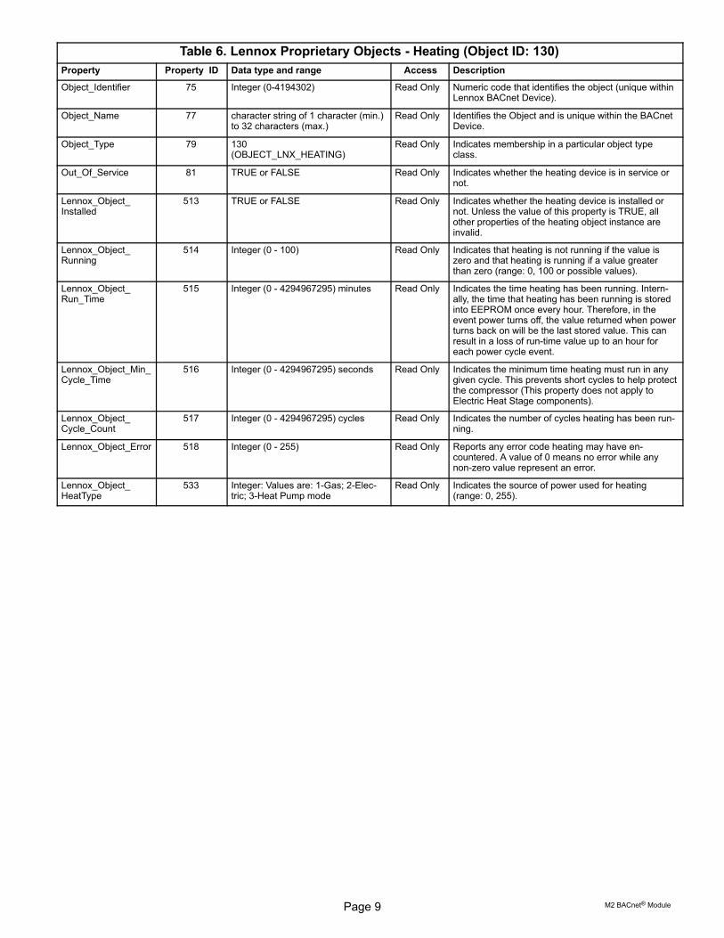
Table 6. Lennox Proprietary Objects - Heating (Object ID: 130)
Property Property ID Data type and range Access Description
Object_Identifier 75 Integer (0-4194302) Read Only Numeric code that identifies the object (unique withinLennox BACnet Device).
Object_Name 77 character string of 1 character (min.)to 32 characters (max.)
Read Only Identifies the Object and is unique within the BACnetDevice.
Object_Type 79 130(OBJECT_LNX_HEATING)
Read Only Indicates membership in a particular object typeclass.
Out_Of_Service 81 TRUE or FALSE Read Only Indicates whether the heating device is in service ornot.
Lennox_Object_Installed
513 TRUE or FALSE Read Only Indicates whether the heating device is installed ornot. Unless the value of this property is TRUE, allother properties of the heating object instance areinvalid.
Lennox_Object_Running
514 Integer (0 - 100) Read Only Indicates that heating is not running if the value iszero and that heating is running if a value greaterthan zero (range: 0, 100 or possible values).
Lennox_Object_Run_Time
515 Integer (0 - 4294967295) minutes Read Only Indicates the time heating has been running. Internally, the time that heating has been running is storedinto EEPROM once every hour. Therefore, in theevent power turns off, the value returned when powerturns back on will be the last stored value. This canresult in a loss of run-time value up to an hour foreach power cycle event.
Lennox_Object_Min_Cycle_Time
516 Integer (0 - 4294967295) seconds Read Only Indicates the minimum time heating must run in anygiven cycle. This prevents short cycles to help protectthe compressor (This property does not apply toElectric Heat Stage components).
Lennox_Object_Cycle_Count
517 Integer (0 - 4294967295) cycles Read Only Indicates the number of cycles heating has been running.
Lennox_Object_Error 518 Integer (0 - 255) Read Only Reports any error code heating may have encountered. A value of 0 means no error while anynon-zero value represent an error.
Lennox_Object_HeatType
533 Integer: Values are: 1-Gas; 2-Electric; 3-Heat Pump mode
Read Only Indicates the source of power used for heating(range: 0, 255).
Page 10Corp. 0926-L11 11/11
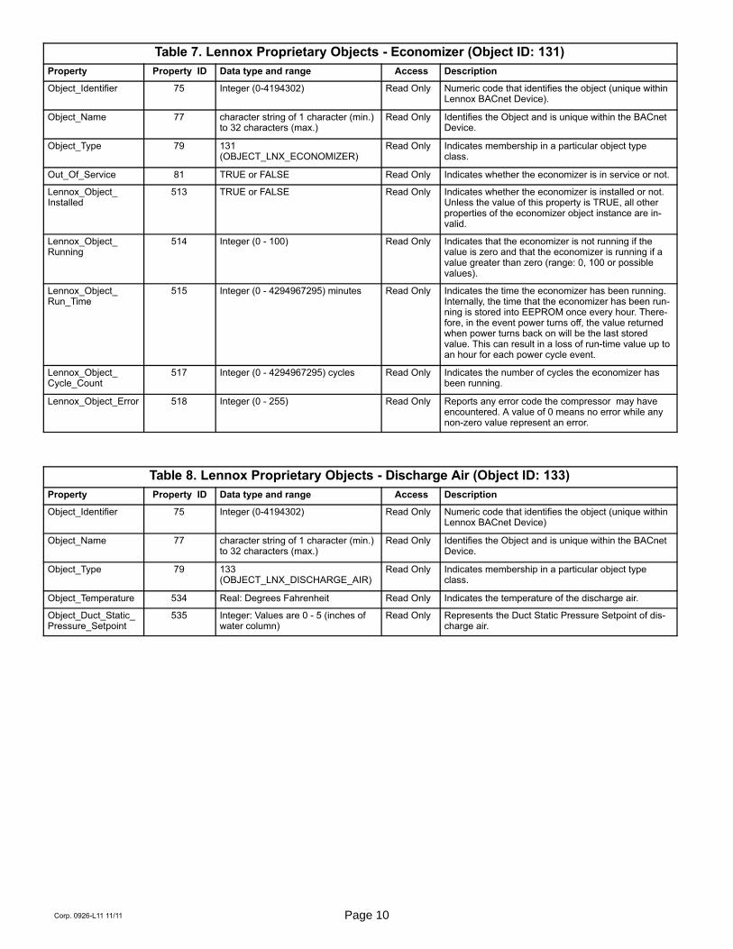
Table 7. Lennox Proprietary Objects - Economizer (Object ID: 131)
Property Property ID Data type and range Access Description
Object_Identifier 75 Integer (0-4194302) Read Only Numeric code that identifies the object (unique withinLennox BACnet Device).
Object_Name 77 character string of 1 character (min.)to 32 characters (max.)
Read Only Identifies the Object and is unique within the BACnetDevice.
Object_Type 79 131(OBJECT_LNX_ECONOMIZER)
Read Only Indicates membership in a particular object typeclass.
Out_Of_Service 81 TRUE or FALSE Read Only Indicates whether the economizer is in service or not.
Lennox_Object_Installed
513 TRUE or FALSE Read Only Indicates whether the economizer is installed or not.Unless the value of this property is TRUE, all otherproperties of the economizer object instance are invalid.
Lennox_Object_Running
514 Integer (0 - 100) Read Only Indicates that the economizer is not running if thevalue is zero and that the economizer is running if avalue greater than zero (range: 0, 100 or possiblevalues).
Lennox_Object_Run_Time
515 Integer (0 - 4294967295) minutes Read Only Indicates the time the economizer has been running.Internally, the time that the economizer has been running is stored into EEPROM once every hour. Therefore, in the event power turns off, the value returnedwhen power turns back on will be the last storedvalue. This can result in a loss of run-time value up toan hour for each power cycle event.
Lennox_Object_Cycle_Count
517 Integer (0 - 4294967295) cycles Read Only Indicates the number of cycles the economizer hasbeen running.
Lennox_Object_Error 518 Integer (0 - 255) Read Only Reports any error code the compressor may haveencountered. A value of 0 means no error while anynon-zero value represent an error.
Table 8. Lennox Proprietary Objects - Discharge Air (Object ID: 133)
Property Property ID Data type and range Access Description
Object_Identifier 75 Integer (0-4194302) Read Only Numeric code that identifies the object (unique withinLennox BACnet Device)
Object_Name 77 character string of 1 character (min.)to 32 characters (max.)
Read Only Identifies the Object and is unique within the BACnetDevice.
Object_Type 79 133(OBJECT_LNX_DISCHARGE_AIR)
Read Only Indicates membership in a particular object typeclass.
Object_Temperature 534 Real: Degrees Fahrenheit Read Only Indicates the temperature of the discharge air.
Object_Duct_Static_Pressure_Setpoint
535 Integer: Values are 0 - 5 (inches ofwater column)
Read Only Represents the Duct Static Pressure Setpoint of discharge air.

Page 11 M2 BACnet® Module
Table 9. Lennox Proprietary Objects - Space Air (Object ID: 133)
Property Property ID Data type and range Access Description
Object_Identifier 75 Integer (0-4194302) Read Only Numeric code that identifies the object (unique withinLennox BACnet Device)
Object_Name 77 character string of 1 character (min.)to 32 characters (max.)
Read Only Identifies the Object and is unique within the BACnetDevice.
Object_Type 79 133(OBJECT_LNX_INDOOR_AIR)
Read Only Indicates membership in a particular object typeclass.
Object_Temperature 534 Real: Degrees Fahrenheit Read Write Indicates the temperature of the space air.
Object_Relative_Humidity
536 Real: Values are 30 to 100 (%RH) Read Write Represents relative humidity of space air.
Object_CO2_Level 537 Real: Values are 30 to 100 (PPM) Read Write Indicates the CO2 levels in the space air.
Table 10. Lennox Proprietary Objects - Outdoor Air (Object ID: 133)
Property Property ID Data type and range Access Description
Object_Identifier 75 Integer (0-4194302) Read Only Numeric code that identifies the object (unique withinLennox BACnet Device)
Object_Name 77 character string of 1 character (min.)to 32 characters (max.)
Read Only Identifies the Object and is unique within the BACnetDevice.
Object_Type 79 133(OBJECT_LNX_OUDOOR_AIR)
Read Only Indicates membership in a particular object typeclass.
Object_Temperature 534 Real: Degrees Fahrenheit Read Write Indicates the temperature of the outdoor air.
Analog Output Objects
Optional Properties Supported: Min_Pres_Value, Max_Pres_Value
Optional Writable Properties: Out_Of_Service
Analog output object's Overridden status flag set if the equivalent setpoint in the M2 is written to by some Sbus device.
Table 11. Analog Output Objects ListObject ID Object Name Units Min. Value Max. Value Valid Values within Range
101 Application Mode Control None 0 255 0,1,3,6,9,208,209,216,217,218,224‐254,255*
102 Outdoor Air Min Pos Control Percent 0 255 all
103 Occupancy Override Control None 0 255 all
104 Occupancy Scheduler Control None 0 255 all
107 Occupancy Sensor Input None 0 255 all
108 Space Dehumidification Setpoint Percent 0 100 all
109 Temperature Setpoint (abs) Deg. F 36.25 100 all
110 Temperature Setpoint Offset Deg. F -32 31.75 all
113 Space Temperature Input Deg. F 36.25 100 all
114 Emergency Override Control None 0 255 all
115 Compressor Enable Control None 0 255 all
117 Primary Heat Enable Control None 0 255 all
119 Auxiliary Heat Enable Control None 0 255 all
123 Duct Static Setpoint In. of water 0 5 all
124 Building Static Setpoint In. of water -0.5 0.5 all
125 Discharge Air Cooling Setpoint Deg. F 40 100 -9,40‐80*
126 Discharge Air Heating Setpoint Deg. F 60 140 -9,80‐140*
127 Supply Fan Capacity Input Percent 33 255 all*
128 Exhaust Fan Capacity Input Percent 33 255 all
129 Set Economizer Outdoor Air Suitable None 0 255 all
* see Application Details section for limitations on data ranges.

Page 12Corp. 0926-L11 11/11
Analog Input Objects
Optional Properties Supported: None
Optional Writable Properties: Out_Of_Service (AI239 - AI252, AI274 - AI285 only)
Page 13 M2 BACnet® Module
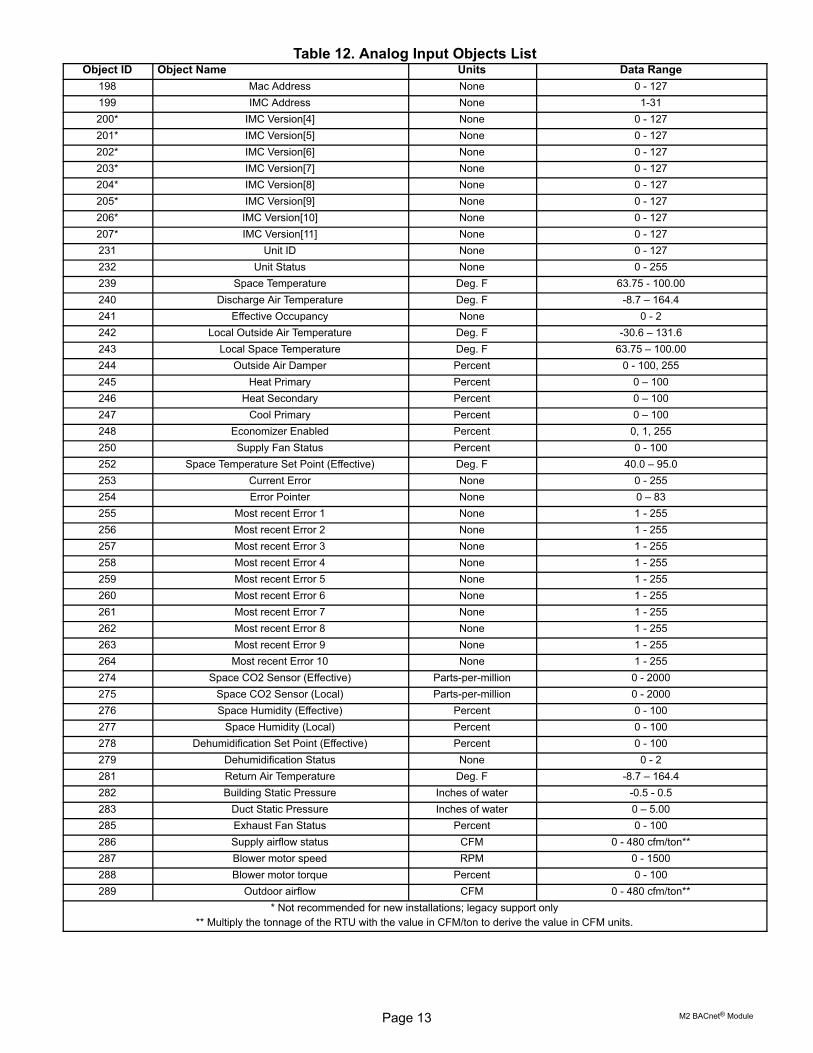
Table 12. Analog Input Objects ListObject ID Object Name Units Data Range
198 Mac Address None 0 - 127
199 IMC Address None 1-31
200* IMC Version[4] None 0 - 127
201* IMC Version[5] None 0 - 127
202* IMC Version[6] None 0 - 127
203* IMC Version[7] None 0 - 127
204* IMC Version[8] None 0 - 127
205* IMC Version[9] None 0 - 127
206* IMC Version[10] None 0 - 127
207* IMC Version[11] None 0 - 127
231 Unit ID None 0 - 127
232 Unit Status None 0 - 255
239 Space Temperature Deg. F 63.75 - 100.00
240 Discharge Air Temperature Deg. F -8.7 – 164.4
241 Effective Occupancy None 0 - 2
242 Local Outside Air Temperature Deg. F -30.6 – 131.6
243 Local Space Temperature Deg. F 63.75 – 100.00
244 Outside Air Damper Percent 0 - 100, 255
245 Heat Primary Percent 0 – 100
246 Heat Secondary Percent 0 – 100
247 Cool Primary Percent 0 – 100
248 Economizer Enabled Percent 0, 1, 255
250 Supply Fan Status Percent 0 - 100
252 Space Temperature Set Point (Effective) Deg. F 40.0 – 95.0
253 Current Error None 0 - 255
254 Error Pointer None 0 – 83
255 Most recent Error 1 None 1 - 255
256 Most recent Error 2 None 1 - 255
257 Most recent Error 3 None 1 - 255
258 Most recent Error 4 None 1 - 255
259 Most recent Error 5 None 1 - 255
260 Most recent Error 6 None 1 - 255
261 Most recent Error 7 None 1 - 255
262 Most recent Error 8 None 1 - 255
263 Most recent Error 9 None 1 - 255
264 Most recent Error 10 None 1 - 255
274 Space CO2 Sensor (Effective) Parts-per-million 0 - 2000
275 Space CO2 Sensor (Local) Parts-per-million 0 - 2000
276 Space Humidity (Effective) Percent 0 - 100
277 Space Humidity (Local) Percent 0 - 100
278 Dehumidification Set Point (Effective) Percent 0 - 100
279 Dehumidification Status None 0 - 2
281 Return Air Temperature Deg. F -8.7 – 164.4
282 Building Static Pressure Inches of water -0.5 - 0.5
283 Duct Static Pressure Inches of water 0 – 5.00
285 Exhaust Fan Status Percent 0 - 100
286 Supply airflow status CFM 0 - 480 cfm/ton**
287 Blower motor speed RPM 0 - 1500
288 Blower motor torque Percent 0 - 100
289 Outdoor airflow CFM 0 - 480 cfm/ton**
* Not recommended for new installations; legacy support only
** Multiply the tonnage of the RTU with the value in CFM/ton to derive the value in CFM units.

Page 14Corp. 0926-L11 11/11
Analog Value Objects
Optional Properties Supported: None
Optional Writable Properties: Present_Value
Table 13. Analog Value Objects List
Object ID Object Name UnitsMin.
ValueMax.Value
Valid Valueswithin Range Note
1 Baud Rate Setting None 9600 76800 9600, 19200, 38400, 76800
130 Heating Occupied Setpoint Deg. F 40 95 all For occupied and unoccupied setpoints considered separately, theheating setpoint must belower than the coolingsetpoint by at least theauto-changeover deadband value set in M2ECTO 6.15 (default 3degF).
131 Cooling Occupied Setpoint Deg. F 40 95 all
132 Heating Unoccupied Setpoint Deg. F 40 95 all
133 Cooling Unoccupied Setpoint Deg. F 40 95 all
134Supply airflow Low SpeedTarget
CFM
1. These objects areapplicable only ifSmartAirflow™ is installed in the system.
2. Object IDs 136 and137 are not applicableto an A box
3. Multiply the tonnageof the RTU with thevalue in CFM/ton toderive the value inCFM units.
135Supply airflow High SpeedTarget
CFM
Refer to the Appendix B for the valid valueranges of these parameters for an A box.
136Supply airflow Medium LowSpeed Target
CFM
137Supply airflow Medium HighSpeed Target
CFM
138Supply airflow Heat ModeTarget
CFM
139 Ventilation airflow Target CFM
140 Smoke airflow Target CFM
141 Outdoor airflow target CFM 0cfm/ton
150cfm/ton
All
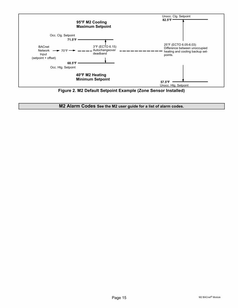
Zone Sensor Setpoints
The M2 typically uses four setpoints and the zonetemperature to operate the unit when a zone sensor isinstalled.
When using the AO:109 single setpoint input, the M2 willuse the zone temperature setpoint and ECTO 6.15 todetermine the heat / cool setpoint in the occupied mode.During the unoccupied mode, the M2 will use the zonetemperature setpoint and the difference between ECTO6.05 and 6.03.
See figure 2 for an example of setpoints when the M2 is
operating using ECTO default values.
As an alternative, the individual setpoints AV:130-133 may
be used. The M2 uses whatever were the last setpoints
received, whether from AO:109-110, or AV:130-133.
Page 15 M2 BACnet® Module
Unocc. Clg. Setpoint
Unocc. Htg. Setpoint
BACnetNetwork
Input (setpoint + offset)
70°F
Occ. Clg. Setpoint
71.5°F
68.5°F
Occ. Htg. Setpoint
95°F M2 CoolingMaximum Setpoint
40°F M2 HeatingMinimum Setpoint
3°F (ECTO 6.15)Autochangeoverdeadband
25°F (ECTO 6.05-6.03)Difference between unoccupiedheating and cooling backup setpoints.
57.5°F
82.5°F
Figure 2. M2 Default Setpoint Example (Zone Sensor Installed)
M2 Alarm Codes See the M2 user guide for a list of alarm codes.

Page 16Corp. 0926-L11 11/11
Application Details
Object Name: Application Mode Control
Object Type: AO (Analog Output)
Object ID: 101
Object Units: (95) No_Units
Value = (See tables below)
Set the application mode input to Value.
The M2 controller can be set locally during commissioning to operate in either of two modes: remote zone sensorcontrol mode (with local or remote zone sensor), or remote thermostat control mode. Several application modecommand values are recognized by either M2 mode, while some can only be used when the M2 is in the remotethermostat control mode.
Common Application Mode Values
Value Mode Description
0 $00 AUTO Heating or cooling. Default after reset.
1 $01 HEAT Heating only.
3 $03 COOL Cooling only.
6 $06 OFF Unit off.
9 $09 FAN ONLY No heating or cooling allowed.
255 $FF NUL Same as AUTO.
208 $D0 FAN AUTO Main fan (blower) auto. Default after reset.
209 $D1 FAN ON Main fan (blower) on.
216 $D8 EXHAUST AUTO Power exhaust fan auto. Default after reset.
217 $D9 EXHAUST1 ON 1st stage power exhaust fan on.
218 $DA EXHAUST1 OFF 1st stage power exhaust fan off.
219 $DB EXHAUST2 ON 2nd stage power exhaust fan on.
220 $DC EXHAUST2 OFF 2nd stage power exhaust fan off.
221 $DD EXHAUST ON Both stages of power exhaust fan on.
222 $DE EXHAUST OFF Both stages of power exhaust fan off.
254 $FE RESET Force controller reset.
The four command groups (0-9), (208-209), (216-222), and (224-236, see below) are independent of each other.Selecting a command from one group does not affect any previously sent command from another group. Except forOFF and RESET, which also set FAN AUTO, EXHAUST AUTO, and heat/cool demand IDLE.
AUTO is the default application mode input. When in a remote zone sensor mode, AUTO allows the M2 control togenerate heating and cooling demands based on zone temperature and zone temperature setpoint. Auxiliary functionssuch as dehumidification or emergency override (i.e. smoke mode) will still operate as needed. Also the blower andexhaust fan functions operate.
HEAT and COOL allow the servicing of only heating or cooling demands. These set a mode only, and do not generate ademand.
Application mode OFF is a unit-disable state, causing the controller to become idle, and clearing all outputs and timers.All outputs are kept off while application mode is OFF. Since this is a complete unit-disable command, it should not beused to turn off heating and cooling demands as part of remote thermostat operation - use 224 IDLE for that purpose.See below.
Application mode FAN ONLY disables heating and cooling operation. No effect on fan operation. Return to normaloperation with AUTO, HEAT, or COOL.
Application modes FAN ON and FAN AUTO are used to turn on the main unit fan (blower), or return it to automaticoperation.
Application modes for EXHAUST ON are used to turn on/off a power exhaust fan, or to return it to automatic operation.The M2 may delay up to 30 seconds before responding to an exhaust command. These commands apply to single-,two-, and variable‐speed power exhausts. A variable‐speed exhaust is enabled here, while the speed is adjusted usingAO:128, the Exhaust Fan Capacity Input.
Application mode RESET causes the system to reset itself and go through the controller's startup and initializationroutines. This takes about 8 seconds in an M2 controller, during which time the analog and digital inputs are settling tocorrect values. The controller will return to AUTO operation.
AUTO, FAN AUTO and EXHAUST AUTO are the defaults after reset.

Page 17 M2 BACnet® Module
Application Modes Specific To Remote Thermostat Operation
These values are only recognized if the M2 control is placed in a remote thermostat mode of operation (set locallyduring commissioning).
Value Mode Y2 Y1 W2 W1 Description
224 $E0 IDLE 0 0 0 0 Heat / Cool off. Default after reset.
228 $E4 COOL1 0 1 0 0 Cool 1.
232 $E8 COOL2 1 0 0 0 Cool 2.
236 $EC COOL3 1 1 0 0 Cool 3. Full cooling.
225 $E1 HEAT1 0 0 0 1 Heat 1.
226 $E2 HEAT2 0 0 1 0 Heat 2.
227 $E3 HEAT3 0 0 1 1 Heat 3. Full heating.
229 $E5 REHEAT LO 0 1 0 1 Supermarket Reheat (lo)
230 $E6 REHEAT HI 0 1 1 1 Supermarket Reheat (hi)
For all $Ex values the fan runs if it is already on, otherwise the fan turns on after a fan on-delay. For $E0 the fan turnsoff after a fan off-delay.
COOL2 and COOL3 are equivalent unless 3-stage cooling has been selected locally at the controller duringcommissioning.
HEAT2 and HEAT3 are equivalent except in heat pump equipment types, when HEAT2 acts as “emergency heat",running auxiliary strip heat and turning off the compressor(s). So in a heat pump, normal heating is commanded usingHEAT1 or HEAT3. REHEAT LO and REHEAT HI can only be used if Supermarket Reheat is enabled for the M2 usingECTO 4.24.
If a mode not defined in the above list is sent, then the application mode is not changed.
When an M2 is commissioned for BACnet® gateway remote thermostat operation, it will wait for 5 minutes followingstartup to receive application mode data. The M2 will remain in AUTO mode until data is received, or until the 5 minuteperiod has expired.
If 5 minutes passes without data being received, then the M2 will enter the backup mode of operation (set locally duringcommissioning).
It is recommended that the application mode data be updated at intervals of no more than 2 minutes to be sure that asingle missed-data event will not constitute an application mode data failure. Any application mode data will serve as avalid update; either common or remote thermostat values.
If application mode data appears while the M2 is in a backup mode, then the M2 will reset and normal operation willresume.
Object Name: Outdoor Air Min Pos Control
Object Type: AO (Analog Output)
Object ID: 102
Object Units: (98) Percent
Value = 0 - 255
0 -100: Set the minimum position of the outdoor air economizer damper; % open.
101 - 255: Relinquish to local control. Min damper position depends on the setting in M2 ECTO 5.24:
ECTO 5.24
=101: Min damper position set by potentiometer on economizer control.
<101: Min damper position set by ECTO 5.24.
The minimum damper position is only effective when the system is occupied and the main blower is running. Otherwisethe damper remains closed. Default value following reset is 101 (local).
Page 18Corp. 0926-L11 11/11
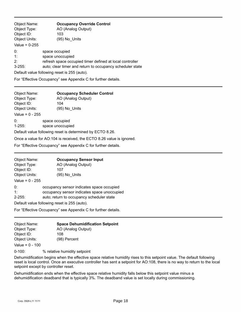
Object Name: Occupancy Override Control
Object Type: AO (Analog Output)
Object ID: 103
Object Units: (95) No_Units
Value = 0-255
0: space occupied
1: space unoccupied
2: refresh space occupied timer defined at local controller
3-255: auto; clear timer and return to occupancy scheduler state
Default value following reset is 255 (auto).
For “Effective Occupancy” see Appendix C for further details.
Object Name: Occupancy Scheduler Control
Object Type: AO (Analog Output)
Object ID: 104
Object Units: (95) No_Units
Value = 0 - 255
0: space occupied
1-255: space unoccupied
Default value following reset is determined by ECTO 8.26.
Once a value for AO:104 is received, the ECTO 8.26 value is ignored.
For “Effective Occupancy” see Appendix C for further details.
Object Name: Occupancy Sensor Input
Object Type: AO (Analog Output)
Object ID: 107
Object Units: (95) No_Units
Value = 0 - 255
0: occupancy sensor indicates space occupied
1: occupancy sensor indicates space unoccupied
2-255: auto; return to occupancy scheduler state
Default value following reset is 255 (auto).
For “Effective Occupancy” see Appendix C for further details.
Object Name: Space Dehumidification Setpoint
Object Type: AO (Analog Output)
Object ID: 108
Object Units: (98) Percent
Value = 0 - 100
0-100: % relative humidity setpoint
Dehumidification begins when the effective space relative humidity rises to this setpoint value. The default followingreset is local control. Once an executive controller has sent a setpoint for AO:108, there is no way to return to the localsetpoint except by controller reset.
Dehumidification ends when the effective space relative humidity falls below this setpoint value minus adehumidification deadband that is typically 3%. The deadband value is set locally during commissioning.

Page 19 M2 BACnet® Module
Object Name: Temperature Setpoint (abs)
Object Type: AO (Analog Output)
Object ID: 109
Object Units: (64) Degrees-Fahrenheit
Value = 36.25 – 100.00 degF, in 0.25 degF increments
The single-point “Temperature Setpoint (abs)" (including offset; see below) is converted locally to occupied andunoccupied heating and cooling setpoints. The occupied and unoccupied heating and cooling setpoints are computedto be centered (if possible) on the effective single-point setpoint. This is done while preserving the occupied andunoccupied deadbands, as well as any local restrictions on minimum or maximum values. The default following reset is70 degF, but local values are used for the heating and cooling (occupied and unoccupied) setpoints until a value isreceived for AO:109.
As an alternative method of establishing setpoints, the individual setpoints AV:130-133 may be used. The M2 useswhatever were the last setpoints received, whether from AO:109-110, or AV:130-133.
The occupied heat/cool auto-changeover deadband value is set locally during commissioning.
The unoccupied heat/cool auto-changeover deadband value is set locally during commissioning by adjusting thebackup unoccupied heating and cooling setpoints. The difference between these setpoints will be used as theunoccupied heat/cool auto-changeover deadband value.
Object Name: Temperature Setpoint Offset
Object Type: AO (Analog Output)
Object ID: 110
Object Units: (64) Degrees-Fahrenheit
Value = -32.00 – 31.75 degF, in 0.25 degF increments
A signed value added to the Temperature Setpoint (abs) value to provide an effective temperature setpoint. See aboveregarding deadbands and limits. The default following reset is 0.
Object Name: Space Temperature Input
Object Type: AO (Analog Output)
Object ID: 113
Object Units: (64) Degrees-Fahrenheit
Value = 36.25 – 100.00 degF, in 0.25 degF increments
A network value for the space temperature. Heating and cooling demands are generated based on the “SpaceTemperature Input", and the “Temperature Setpoint (abs)" and “Temperature Setpoint Offset" values. See above. Thedefault following reset is 72.5 degF.
When an M2 is commissioned for BACnet® gateway remote room sensor operation, it will wait for 5 minutes followingstartup to receive space temperature data. The M2 will remain in a no-run mode until data is received, or until the 5minute period has expired.
If 5 minutes passes without data being received, then the M2 begins to use local data for the space temperature. If alocal sensor is connected then it will be used. If not, then a failed-sensor error is recorded and the M2 will enter thebackup mode of operation (set locally during commissioning).
It is recommended that network data be updated at intervals of no more than 2 minutes to be sure that a singlemissed-data event will not constitute a data update failure.
If data appears after a sensor failure is processed, it will be treated as an intermittent sensor. Normal operation willresume. If the M2 is in a backup mode, then it will reset before resuming.

Page 20Corp. 0926-L11 11/11
Object Name: Emergency Override Control
Object Type: AO (Analog Output)
Object ID: 114
Object Units: (95) No_Units
Value = 0 - 255
Set the emergency mode defined by value, decoded as:
Supply Exhaust Outdoor
Value Mode Fan Fan Damper
0 NORMAL auto auto auto
1 PRESSURIZE on off open
2 DEPRESSURIZE off on (speed) closed
3 PURGE on on (speed) open
4 SHUTDOWN off off closed
5 FIRE
6 DEPRESSURIZE off on (pressure) closed
7 PURGE on on (pressure) open
>7 NUL (normal) auto auto auto
auto - normal operation
(speed) - exhaust fan runs at speed pre-selected at equipment
(pressure) - exhaust fan runs to maintain building press setpoint; local or remote
Mode 5, FIRE, is a locally defined operation (set at commissioning).
For units without VFD exhaust fans, modes 6-7 are the same as 2-3.
“Emergency Override Control" input takes precedence over local smoke input. The default following reset is 0(NORMAL).
Object Name: Compressor Enable Control
Object Type: AO (Analog Output)
Object ID: 115
Object Units: (98) Percent
Value = 0 - 255
0: output disabled
1-100: output limited to 1 – 100% of maximum
101-255: maximum output permitted
The following table shows the value where the indicated compressor stage is disabled, for equipment having theindicated maximum number of compressor stages:
Maximum Stage Disabled When Value < xStages 1 2 3 4
1 Value < 50
2 Value < 33 Value < 66
3 Value < 25 Value < 50 Value < 75
4 Value < 20 Value < 40 Value < 60 Value < 80
Free cooling using an economizer with outdoor air is not considered a stage. Only compressors are considered to bestages. All compressors installed are included, however they are being used; sensible cooling, condenser reheat (latentcooling), or heat pump heating. The default following reset is 100%.
Disabled stages are re-enabled at the above values plus 3% hysteresis.

Page 21 M2 BACnet® Module
Object Name: Primary Heat Enable Control
Object Type: AO (Analog Output)
Object ID: 117
Object Units: (98) Percent
Value = 0 - 255
0: output disabled
1-100: output limited to 1 – 100% of maximum
101-255: maximum output permitted
The table shown above for “Compressor Enable Control" can also be applied here to the “Primary Heat EnableControl". It shows the value where the indicated primary heating stage is disabled, for equipment having the indicatedmaximum number of primary heating stages. The default following reset is 100%.
In heat pump systems during heating operation, the lower value of “Compressor Enable Control" and “Primary HeatEnable Control" is used to establish the compressors that can run.
Object Name: Auxiliary Heat Enable Control
Object Type: AO (Analog Output)
Object ID: 119
Object Units: (98) Percent
Value = 0 - 255
0: output disabled
1-100: output limited to 1 – 100% of maximum
101-255: maximum output permitted
The table shown above for “Compressor Enable Control" can also be applied here to the “Auxiliary Heat EnableControl". It shows the value where the indicated auxiliary heating stage is disabled, for equipment having the indicatedmaximum number of auxiliary heating stages. The default following reset is 100%.
The “Auxiliary Heat Enable Control" is only used in heat pump systems.
Object Name: Duct Static Setpoint
Object Type: AO (Analog Output)
Object ID: 123
Object Units: (58) Inches-of-water
Value = 0.0 - 5.0 inWC
The setpoint for control of duct static pressure, in inches of water column. The main blower speed or bypass dampersetting is varied to maintain this value. The setpoint can be selected from the range of 0.0 to 5.0 inches of watercolumn. The default following reset is local control. Once an executive controller has sent a setpoint for AO:123, thereis no way to return to the local setpoint except by controller reset.
Object Name: Building Static Setpoint
Object Type: AO (Analog Output)
Object ID: 124
Object Units: (58) Inches-of-water
Value = -0.5 - 0.5 inWC
The setpoint for control of building static pressure, in inches of water column. The exhaust blower is cycled or, if a VFDis used, its speed is varied to maintain this value. The setpoint can be selected from the range of -0.5 to +0.5 inches ofwater column. The default following reset is local control. Once an executive controller has sent a setpoint for AO:124,there is no way to return to the local setpoint except by controller reset.

Page 22Corp. 0926-L11 11/11
Object Name: Discharge Air Cooling Setpoint
Object Type: AO (Analog Output)
Object ID: 125
Object Units: (64) Degrees-Fahrenheit
Value = 40 - 80 degF, and -9 degF
The setpoint for control of discharge (or supply) air temperature during cooling. When the controller is in the correctmode of operation, sending this setpoint will cause cooling components to cycle, or vary their output, in order tomaintain this temperature in the leaving air stream. The setpoint can be selected from the range of 40 to 80 degreesFahrenheit. Selecting a value of -9 degF causes the control to revert to the use of its locally programmed setpoint.Default value following reset is -9 (local).
Object Name: Discharge Air Heating Setpoint
Object Type: AO (Analog Output)
Object ID: 126
Object Units: (64) Degrees-Fahrenheit
Value = 80 - 140 degF, and -9 degF
The setpoint for control of discharge (or supply) air temperature during heating. When the controller is in the correctmode of operation, sending this setpoint will cause heating components to cycle, or vary their output, in order tomaintain this temperature in the leaving air stream. The setpoint can be selected from the range of 80 to 140 degreesFahrenheit. Selecting a value of -9 degF causes the control to revert to the use of its locally programmed setpoint.Default value following reset is -9 (local).
Object Name: Supply Fan Capacity Input
Object Type: AO (Analog Output)
Object ID: 127
Object Units: (98) Percent
Value = 33 - 255
33 - 100: Set the supply fan capacity as a % of maximum speed.101 - 255: Relinquish to local control. Supply fan capacity depends on M2 ECTO values.
Supply fan capacity is only effective when the main blower is running.
if compressor(s) are on or heat is on, min. value is limited to ECTO 0.06 or ECTO 0.07, respectively.
Maximum supply air is limited by M2 ECTO value 0.08, although the relinquish default range of 101-255 is alwaysavailable. Default value following reset is 255 (local).
Object Name: Exhaust Fan Capacity Input
Object Type: AO (Analog Output)
Object ID: 128
Object Units: (98) Percent
Value = 33 - 255
33 - 100: Set the exhaust fan capacity as a % of maximum speed.101 - 255: Relinquish to local control. Exhaust fan capacity depends on M2 ECTO values.
Exhaust fan capacity is only effective when the exhaust fan is running. Default value following reset is 255 (local).

Page 23 M2 BACnet® Module
Object Name: Set Economizer Outdoor Air Suitable
Object Type: AO (Analog Output)
Object ID: 129
Object Units: (95) No_Units
Value = 0-255
0: Economizer disable1: Economizer enable>1: Economizer to auto
When outdoor air is determined to be suitable for free cooling, the economizer feature will operate (if installed) on a firststage cooling call to use outdoor air instead of mechanical cooling. AO:129 is used to allow an executive controller toset the state of outdoor air suitability (OAS). It can be enabled, disabled, or left for the local controller to determine.
BACnet control of the economizer requires the the M2 to have DIP switches selected to TMP temperature mode. Seethe M2 manual for additional information on economizer operation. Default value following reset is 255 (auto).
Object Name: MAC Address
Object Type: AI (Analog Input)
Object ID: 198
Object Units: (95) No_Units
Value = 0-127
Selectable BACnet MAC address. By default, this value equals the L Connection address.
Object Name: IMC Address
Object Type: AI (Analog Input)
Object ID: 199
Object Units: (95) No_Units
Value = 1-31
Selectable L Connection address (1-31). This address is used for L Connection network.
Object Name: IMC Version[04], IMC Version[05], �, IMC Version[11]
Object Type: AI (Analog Input)
Object ID: 200, 201, …, 207
Object Units: (95) No_Units
Value = 0, 46, 48 - 57
0: end of string
46: “."
48: “0"
…57: “9"
Each value is the ASCII code of a character in the M2 version number. The version number is found in a null-terminatedstring, most-significant-character first, beginning in IMC Version[04]. Maximum length is 8 chars, including null.
NOTE - Not recommended for new installations. Read device object property Application_Software_Version instead.For BACnet version read device object property Firmware_Revision.
Page 24Corp. 0926-L11 11/11
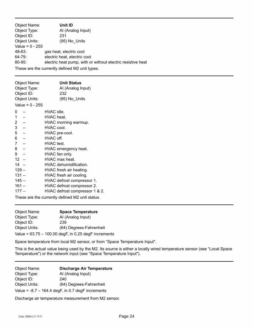
Object Name: Unit ID
Object Type: AI (Analog Input)
Object ID: 231
Object Units: (95) No_Units
Value = 0 - 255
48-63: gas heat, electric cool
64-79: electric heat, electric cool
80-95: electric heat pump, with or without electric resistive heat
These are the currently defined M2 unit types.
Object Name: Unit Status
Object Type: AI (Analog Input)
Object ID: 232
Object Units: (95) No_Units
Value = 0 - 255
0 – HVAC idle.
1 – HVAC heat.
2 – HVAC morning warmup.
3 – HVAC cool.
5 – HVAC pre-cool.
6 – HVAC off.
7 – HVAC test.
8 – HVAC emergency heat.
9 – HVAC fan only.
12 – HVAC max heat.
14 – HVAC dehumidification.
129 – HVAC fresh air heating.
131 – HVAC fresh air cooling.
145 – HVAC defrost compressor 1.
161 – HVAC defrost compressor 2.
177 – HVAC defrost compressor 1 & 2.
These are the currently defined M2 unit status.
Object Name: Space Temperature
Object Type: AI (Analog Input)
Object ID: 239
Object Units: (64) Degrees-Fahrenheit
Value = 63.75 – 100.00 degF, in 0.25 degF increments
Space temperature from local M2 sensor, or from “Space Temperature Input".
This is the actual value being used by the M2. Its source is either a locally wired temperature sensor (see “Local SpaceTemperature") or the network input (see “Space Temperature Input").
Object Name: Discharge Air Temperature
Object Type: AI (Analog Input)
Object ID: 240
Object Units: (64) Degrees-Fahrenheit
Value = -8.7 – 164.4 degF, in 0.7 degF increments
Discharge air temperature measurement from M2 sensor.
Page 25 M2 BACnet® Module
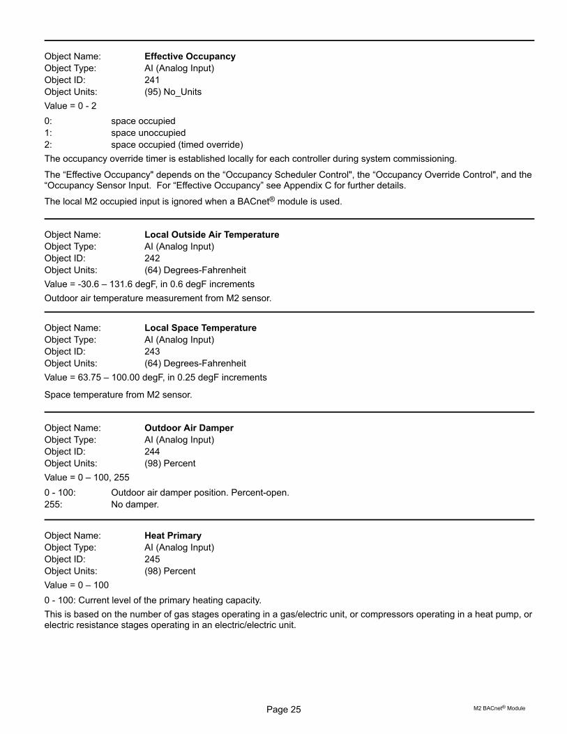
Object Name: Effective Occupancy
Object Type: AI (Analog Input)
Object ID: 241
Object Units: (95) No_Units
Value = 0 - 2
0: space occupied
1: space unoccupied
2: space occupied (timed override)
The occupancy override timer is established locally for each controller during system commissioning.
The “Effective Occupancy" depends on the “Occupancy Scheduler Control", the “Occupancy Override Control", and the“Occupancy Sensor Input. For “Effective Occupancy” see Appendix C for further details.
The local M2 occupied input is ignored when a BACnet® module is used.
Object Name: Local Outside Air Temperature
Object Type: AI (Analog Input)
Object ID: 242
Object Units: (64) Degrees-Fahrenheit
Value = -30.6 – 131.6 degF, in 0.6 degF increments
Outdoor air temperature measurement from M2 sensor.
Object Name: Local Space Temperature
Object Type: AI (Analog Input)
Object ID: 243
Object Units: (64) Degrees-Fahrenheit
Value = 63.75 – 100.00 degF, in 0.25 degF increments
Space temperature from M2 sensor.
Object Name: Outdoor Air Damper
Object Type: AI (Analog Input)
Object ID: 244
Object Units: (98) Percent
Value = 0 – 100, 255
0 - 100: Outdoor air damper position. Percent-open.
255: No damper.
Object Name: Heat Primary
Object Type: AI (Analog Input)
Object ID: 245
Object Units: (98) Percent
Value = 0 – 100
0 - 100: Current level of the primary heating capacity.
This is based on the number of gas stages operating in a gas/electric unit, or compressors operating in a heat pump, orelectric resistance stages operating in an electric/electric unit.
Page 26Corp. 0926-L11 11/11
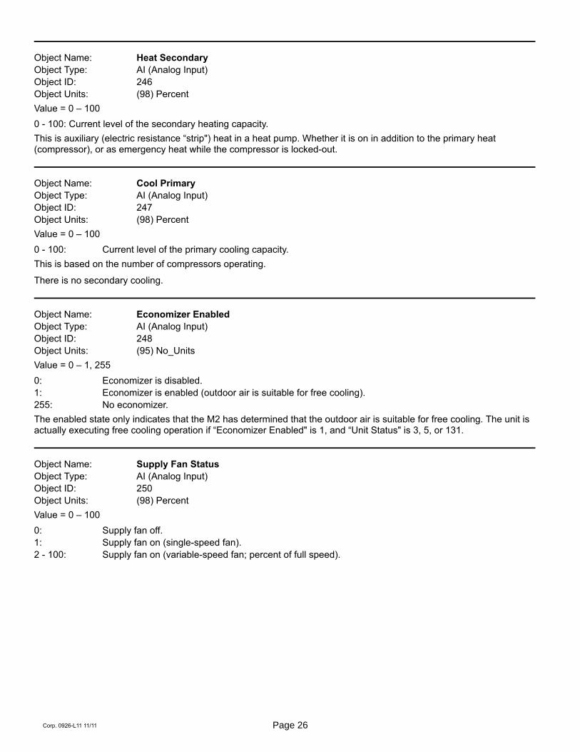
Object Name: Heat Secondary
Object Type: AI (Analog Input)
Object ID: 246
Object Units: (98) Percent
Value = 0 – 100
0 - 100: Current level of the secondary heating capacity.
This is auxiliary (electric resistance “strip") heat in a heat pump. Whether it is on in addition to the primary heat(compressor), or as emergency heat while the compressor is locked-out.
Object Name: Cool Primary
Object Type: AI (Analog Input)
Object ID: 247
Object Units: (98) Percent
Value = 0 – 100
0 - 100: Current level of the primary cooling capacity.
This is based on the number of compressors operating.
There is no secondary cooling.
Object Name: Economizer Enabled
Object Type: AI (Analog Input)
Object ID: 248
Object Units: (95) No_Units
Value = 0 – 1, 255
0: Economizer is disabled.
1: Economizer is enabled (outdoor air is suitable for free cooling).
255: No economizer.
The enabled state only indicates that the M2 has determined that the outdoor air is suitable for free cooling. The unit isactually executing free cooling operation if “Economizer Enabled" is 1, and “Unit Status" is 3, 5, or 131.
Object Name: Supply Fan Status
Object Type: AI (Analog Input)
Object ID: 250
Object Units: (98) Percent
Value = 0 – 100
0: Supply fan off.
1: Supply fan on (single-speed fan).
2 - 100: Supply fan on (variable-speed fan; percent of full speed).

Page 27 M2 BACnet® Module
Object Name: Space Temperature Setpt (Eff)
Object Type: AI (Analog Input)
Object ID: 252
Object Units: (64) Degrees-Fahrenheit
Value = 40.0 – 95.0 degF, in 0.25 degF increments
The effective space temperature setpoint, which depends on:
current “Temperature Setpoint (abs)",
current “Temperature Setpoint Offset",
current “Effective Occupancy",
most recent heating or cooling demand indicated by “Unit Status",
any local setpoint adjustment,
and heating and cooling deadbands and differentials set at system commissioning.
Object Name: Current Error
Object Type: AI (Analog Input)
Object ID: 253
Object Units: (95) No_Units
Value = 0 - 255
This is the code for the currently occurring alarm condition, if any. If no alarm is currently in progress, then the value is0. If the value is not zero, then “Current Error" and “Most Recent Error 1" (see below) will be equal.
Refer to the M2 User's Guide for alarm code descriptions.
Object Name: Error Pointer
Object Type: AI (Analog Input)
Object ID: 254
Object Units: (95) No_Units
Value = 0 - 83
This value points to the next available alarm code location. It runs from 0 to 83, and then rolls-over to 0. Tracking thisvalue and using the ten-most-recent-error-codes (see below) allows an application to determine when new errors arelogged by the M2, what those errors are, and if any errors have been missed due to network delays or for any otherreason.
To correct for an error in some early versions, if the reported value is in the range of 164-247 then it is necessary tosubtract it from 247 in order to get the 0-83 value described above.
Page 28Corp. 0926-L11 11/11
Object Name: Most recent Error 1,
Most recent Error 2
Most recent Error 10
Object Type: AI (Analog Input)
Object ID: 255, 256, …, 264
Object Units: (95) No_Units
Value = 1 - 255
These are the ten most recently occurring diagnostic codes; “Most recent Error 1" is the most recent.
This is a first-in first-out buffer. Error codes are stored as they occur, and no filtering is done with respect to duplicationor error code severity or priority.
When another error code is logged at “Most recent Error 1", the value in “Most recent Error 10" is lost, being replacedby “Most recent Error 9".
Refer to the M2 User's Guide for alarm code descriptions.
Object Name: Space CO2 Sensor (Eff)
Object Type: AI (Analog Input)
Object ID: 274
Object Units: (96) Parts-per-million
Value = 0 - 2000
0 - 6: no sensor
7 - 1992: valid CO2 measurement
1993 - 2000: sensor error
This is the actual value being used by the M2, and is the value measured at the M2.
Object Name: Space CO2 Sensor (Local)
Object Type: AI (Analog Input)
Object ID: 275
Object Units: (96) Parts-per-million
Value = 0 - 2000
0 - 6: no sensor
7 - 1992: valid CO2 measurement
1993 - 2000: sensor error
This is the actual value being used by the M2, and is the value measured at the M2.

Page 29 M2 BACnet® Module
Object Name: Space Humidity (Eff)
Object Type: AI (Analog Input)
Object ID: 276
Object Units: (98) Percent
Value = 0 - 100
0: no sensor
1 - 99: valid relative humidity measurement
100: sensor error
This is the actual value being used by the M2, and is the value measured at the M2.
Object Name: Space Humidity (Local)
Object Type: AI (Analog Input)
Object ID: 277
Object Units: (98) Percent
Value = 0 - 100
0: no sensor
1 - 99: valid relative humidity measurement
100: sensor error
This is the actual value being used by the M2, and is the value measured at the M2.
Object Name: Dehumidification Set Point (Eff)
Object Type: AI (Analog Input)
Object ID: 278
Object Units: (98) Percent
Value = 0 - 100
Relative humidity setpoint for dehumidification operation.
Deadband is set locally during commissioning.
Object Name: Dehumidification Status
Object Type: AI (Analog Input)
Object ID: 279
Object Units: (95) No_Units
Value = 0 – 2
0: No dehumidification installed.
1: Dehumidification installed but not running.
2: Dehumidification installed and running.
Page 30Corp. 0926-L11 11/11
Object Name: Return Air Temperature
Object Type: AI (Analog Input)
Object ID: 281
Object Units: (64) Degrees-Fahrenheit
Value = -8.7 – 164.4 degF, in 0.7 degF increments
Unit return air temperature measurement from M2 sensor.
Object Name: Building Static Pressure
Object Type: AI (Analog Input)
Object ID: 282
Object Units: (58) Inches-of-water
Value = -0.500 – 0.500 inWC, in 0.004 inWC increments
Building (space) static pressure measurement from M2 sensor.
Object Name: Duct Static Pressure
Object Type: AI (Analog Input)
Object ID: 283
Object Units: (58) Inches-of-water
Value = 0.00 – 5.00 inWC, in 0.02 inWC increments
Duct (supply) static pressure measurement from M2 sensor.
Object Name: Exhaust Fan Status
Object Type: AI (Analog Input)
Object ID: 285
Object Units: (98) Percent
Value = 0 – 100
0: Exhaust fan off.
1: Exhaust stage 1 on.
2: Exhaust stage 2 on.
33-100: Exhaust variable speed %on.
255: No exhaust.
Object Name: Supply Airflow Status
Object Type: AI (Analog Input)
Object ID: 286
Object Units: (84) Cubic Feet per Minute
Value = 0 – 480 cfm/ton
This object gives the current value of Supply Airflow as calculated by the Prodigy controller if SmartAirflow™ isinstalled.
Object Name: Blower Motor Speed
Object Type: AI (Analog Input)
Object ID: 287
Object Units: (104) Revolutions per Minute
Percent Value = 0 – 1500 RPM
This object gives the current speed of the Blower Motor if SmartAirflow™ is installed.
Page 31 M2 BACnet® Module
Object Name: Blower Motor Torque
Object Type: AI (Analog Input)
Object ID: 288
Object Units: (98) Percent Value = 0, 20 – 100
0: Blower is OFF.
20: Minimum Blower Torque.
100: Maximum Blower Torque
This object gives the current value of the blower PWM for an ECM type of Blower Motor if SmartAirflow™ is installed.
Object Name: Outdoor Airflow
Object Type: AI (Analog Input)
Object ID: 289
Object Units: (84) Cubic Feet per Minute
Value = 0 – 480 cfm/ton
The amount of outdoor airflow that is entering through the outdoor damper as calculated by Prodigy controller ifSmartAirflow™ is installed.
Object Name: Baud Rate Setting
Object Type: AV (Analog Value)
Object ID: 1
Object Units: (95) No Units
Value = 9600, 19200, 38400, 76800
Baud rate change only takes affect after M2 resets. Default value following reset is 38400, but this can be changed atthe unit. See M2 manual for details.
Object Name: Heating Occupied Setpoint
Object Type: AV (Analog Value)
Object ID: 130
Object Units: (64) Degrees‐Fahrenheit
Value = 40 - 95
Occupied heating setpoint. Default value following reset is local (ECTO 6.02).
As an alternative method of establishing setpoints, the single setpoint AO:109 and offset AO:110 may be used. The M2uses whatever were the last setpoints received, whether from AO:109-110, or AV:130-133.
To be considered in range the values for AV:130, 131, 132, and 133 must be in the range 40-95, and the heatingsetpoint must be less than the corresponding (occupied or unoccupied) cooling setpoint by at least theauto-changeover deadband value set in M2 ECTO 6.15 (default 3°F, 2-10°F range). If any of these condition is areviolated, BACnet will return an out of range message. The AV's 130-133 can be used instead of the single setpoint andoffset AO:109 and AO:110.
Object Name: Cooling Occupied Setpoint
Object Type: AV (Analog Value)
Object ID: 131Object Units: (64) Degrees‐Fahrenheit
Value = 40 - 95
Occupied cooling setpoint. Default value following reset is local (ECTO 6.04). See description for AV:130 for details onvalid range.
Page 32Corp. 0926-L11 11/11
Object Name: Heating Unoccupied Setpoint
Object Type: AV (Analog Value)
Object ID: 132
Object Units: (64) Degrees‐Fahrenheit
Value = 40 - 95
Unoccupied heating setpoint. Default value following reset is local (ECTO 6.03). See description for AV:130 for detailson valid range.
Object Name: Cooling Unoccupied Setpoint
Object Type: AV (Analog Value)
Object ID: 133
Object Units: (64) Degrees‐Fahrenheit
Value = 40 - 95
Unoccupied cooling setpoint. Default value following reset is local (ECTO 6.05). See description for AV:130 for detailson valid range.
Object Name: Supply Airflow Low Speed Target
Object Type: AV (Analog Value)
Object ID: 134
Object Units: (84)Cubic Feet per Minute
This object will set the default of Supply airflow Low Speed Target (ECTO 10.1) following a reset. This is applicable onlyfor systems with SmartAirflow™ installed. See appendix B for the details on valid ranges.
Object Name: Supply Airflow High Speed Target
Object Type: AV (Analog Value)
Object ID: 135
Object Units: (84)Cubic Feet per Minute
This object will set the default of Supply airflow High speed target (ECTO 10.2) following a reset. This is applicable onlyfor systems with SmartAirflow™ installed. See appendix B for the details on valid ranges.
Object Name: Supply Airflow Medium Low Speed Target
Object Type: AV (Analog Value)
Object ID: 136
Object Units: (84)Cubic Feet per Minute
This object will set the default of Supply airflow Medium Low Speed Target (ECTO 10.3) following a reset. This isapplicable only for systems with SmartAirflow™ installed and for non Abox.
Object Name: Supply Airflow Medium High Speed Target
Object Type: AV (Analog Value)
Object ID: 137
Object Units: (84)Cubic Feet per Minute
This object will set the default of Supply airflow Medium High Speed Target (ECTO 10.4) following a reset. This isapplicable only for systems with SmartAirflow™ installed and for non Abox.

Page 33 M2 BACnet® Module
Object Name: Supply Airflow Heat Mode Target
Object Type: AV (Analog Value)
Object ID: 138
Object Units: (84)Cubic Feet per Minute
This object will set the default of Supply airflow Heat Mode target (ECTO 10.5) following a reset. This is applicable onlyfor systems with SmartAirflow™ installed. See appendix B for the details on valid ranges.
Object Name: Ventilation Airflow Target
Object Type: AV (Analog Value)
Object ID: 139
Object Units: (84)Cubic Feet per Minute
This object will set the default of Ventilation Airflow Target (ECTO 10.6) following a reset. This is applicable only forsystems with SmartAirflow™ installed. See appendix B for the details on valid ranges.
Object Name: Smoke Airflow Target
Object Type: AV (Analog Value)
Object ID: 140
Object Units: (84)Cubic Feet per Minute
This object will set the default of Smoke Airflow target (ECTO 10.8) following a reset. This is applicable only for systemswith SmartAirflow™ installed. See appendix B for the details on valid ranges.
Object Name: Outdoor Airflow Target
Object Type: AV (Analog Value)
Object ID: 141
Object Units: (84)Cubic Feet per Minute
This object will set the default of Smoke Airflow target (ECTO 10.17) following a reset. This is applicable only forsystems with SmartAirflow™ installed. See appendix B for the details on valid ranges.

Page 34Corp. 0926-L11 11/11
Appendix A. Timeline of M2 startup sequences
Remote Demand modesECTO 6.01 = [4,7]ECTO 5.27 = 0
Zone Sensor with Network sensorsECTO 6.01 = [1,3]ECTO 5.27 = 2
Zone SensormodesECTO 6.01 = [1,3]ECTO 5.27 = 0
Remote demand not received. Remote demand
timer (REMOTE_TMR) fails
Network sensor data notreceived. Network sensortimer (A2DOVRTMR) fails
Remote demand received.BACnet timer (15 mins) starts
and is refreshed at each remote demand packet.
Network sensor data received.BACnet timer (15 mins) starts.
Timer refreshed at eachBACnet packet.
Network sensor timerstarts/ (A2DOVRTMR).
Network settings received.BACnet timer (15 mins)
starts. Timer refreshed ateach BACnet packet.
NO OPERATION
RTU IDLE
RTU IDLE
RESET T=0s T=8s 2 mins 5 mins
ECTO 6.01 = 0; ECTO 5.27 = 0System mode is Local Thermostat
System mode is Zone Sensor Backup mode
System mode is Zone Sensor mode
Communication failureBACnet timer expires=> M2 controller resets
System mode is Zone Sensor modeNetwork sensor data received - timer ok
System mode is Zone Sensor modeNetwork sensor data received - timer ok
ECTO 6.01 = 3; Zone sensor backupmode, Local ZAT; RAT if local ZAT fails
ECTO 6.01 = 2 or Local ZAT and RAT fail. Zonesensor backup mode (Local Thermostat)
System mode is Remote Demand mode
System mode is Remote Demand mode
Network sensor datareceived - timer restarts
ECTO 6.01 = 7; Remote demand backup mode (ZAT)
ECTO 6.01 = 6 or Local ZAT fails, Remote demand backup mode (RAT)
ECTO 6.01 = 4 or Local ZAT and RAT sensors fail, RTU in IDLE mode
No network demand in15 minutes. BACnet
communication failure.

Page 35 M2 BACnet® Module
APPENDIX B The maximum and minimum values of Supply Airflow Targets in CFM units are as below.
UNIT SIZE 36 48 60
Maximum High Speed Target & Heat Mode Target (480 CFM/ton) 1440 1920 2400
Minimum High Speed Target (280 CFM/ton) 840 1120 1400
Minimum Low Speed Target (220 CFM/ton) 660 880 1100
Minimum Ventilation Target (150 CFM/ton) 450 600 750
Minimum Heat Mode Target Standard Gas Heat (S,W) 970 970 970
Minimum Heat Mode Target Medium Gas Heat (M, Q, U, Y) 1120 1120 1120
Minimum Heat Mode Target High Gas Heat Minimum (H, T, X, Z) 1310 1310 1310
Minimum Heat Mode Target Electric Heat 1080 1280 1600
Maximum Outdoor Airflow (150 cfm/ton) 450 600 750
Note:
1. Maximum Ventilation Target should be less than High Speed Target or Heat Mode Target
2. Maximum Low Speed Target should be less than High Speed Target

Page 36Corp. 0926-L11 11/11
APPENDIX C — PRODIGY M2 UNIT CONTROLLER BLOWER OPERATIONS
This section describes how BACnet® occupancy signalsare combined to produce effective occupancy.
The blower runs to service heat and cool demands,regardless of the space occupancy. But when there is noheating or cooling demand there are options for how theblower should operate in conjunction with occupancysignals to keep the space ventilated, or the air stirred.
In SETTINGS > CONTROL menus the option forBLOWER ON OCP is selected as CYCLES or ALWAYSON. These correspond to ECTO 6.17 settings of 0 or 1,respectively. These settings govern whether the blowerruns continuously when the space is considered occupied(=1), or cycles on/off with the heating and cooling demand(=0). ECTO 6.17 only applies to the room sensor controlmodes, and not to the local or network thermostat modes.In those modes the blower is controlled by the Gthermostat or DDC signal.
To comply with the California Energy Commission Title 24standard there are two additional blower/occupancysettings that are set directly by changing ECTO 6.17 fromthe SETTINGS>CONTROL > ECTO menu. These twoadditional options are available when using LonTalk orBACnet networks that supplies a room occupancy signal(in addition to the scheduled occupancy).
The same two options are also available when using theLennox L Connection network with comfort sensors thathave added an optional room occupancy sensor. If a roomoccupancy sensor is not installed and configured on thenetwork, then options 0 and 1 for ECTO 6.17 as previouslydescribed should continue to be used.
The two new CEC Title 24 settings for ECTO 6.17 areoptions 2 and 3 and a description of both are provided intable 14.
Table 14. ECTO 6.17 Description
ECTO6.17
Occupancy Blower Duty Description
0 Blower cycles on/off with demand. (Legacy usage.)
1 Blower runs when either the occupancy sensor or schedule, or both, indicates occupied. (Legacy usage.)
2 Blower runs when both the occupancy sensor and schedule indicate occupied.
3The same as option 2, but blower runs for 30 minutes and is off for 90 minutes when schedule is occupied but the occupancy sensor isnot occupied.
Table 15. BACnet Occupancy Points
BACnet Value
ManualOccupancy Override Control
AO 103
0: space occupied
1: space unoccupied
2: refresh space occupied override timer
3255: auto; clear timer and return to scheduler
ScheduleOccupancy Scheduler Control
AO 104
0: space occupied
1255: space unoccupied
SensorOccupancy Sensor Input
AO 107
0: space occupied
1: space unoccupied
2255: auto; return to occupancy scheduler state
EffectiveOccupancy
Effective OccupancyAI 241
0: space occupied
1: space unoccupied
2: space occupied (timed override)
Table 16. Blower Operation Description
Blower Operation Description
On Blower runs continuously.
Cycles Blower cycles on/off with demand.
Cycles w/Stir Blower cycles on/off with demand; during off cycle blower is on 30 minutes of 120.
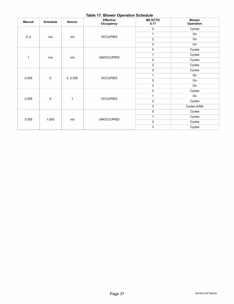
Page 37 M2 BACnet® Module
Table 17. Blower Operation Schedule
Manual Schedule SensorEffective
OccupancyM2 ECTO
6.17Blower
Operation
0, 2 n/a n/a OCCUPIED
0 Cycles
1 On
2 On
3 On
1 n/a n/a UNOCCUPIED
0 Cycles
1 Cycles
2 Cycles
3 Cycles
3255 0 0, 2-255 OCCUPIED
0 Cycles
1 On
2 On
3 On
3255 0 1 OCCUPIED
0 Cycles
1 On
2 Cycles
3 Cycles w/Stir
3255 1255 n/a UNOCCUPIED
0 Cycles
1 Cycles
2 Cycles
3 Cycles

Page 38Corp. 0926-L11 11/11
BACnet® Protocol Implementation Conformance (PIC) Statement
Date July 11, 2011. . . . . . . . . . . . . . . . . . . . . .Vendor Name Lennox Industries, Inc.. . . . . . . . . . . . . .Product Name Prodigy Rooftop Unit Controller. . . . . . . . . . . . .Product Model Number M2. . . . .Firmware Revision 1.00h. . . . . . . . .Application Software Version 7.08.xx.BACnet Protocol Revision 7. . .
Product DescriptionHVAC controller designed to control Lennox commercial rooftop units.
BACnet® Standardized Device Profile (Annex L) BACnet Operator Workstation (B-OWS)
BACnet Building Controller (B-BC)
BACnet Advanced Application Controller (B-AAC)
x BACnet Application Specific Controller (B-ASC)
BACnet Smart Sensor (B-SS)
BACnet Smart Actuator (B-SA)
BACnet® Interoperability Building Blocks (BIBBs) Supported (Annex K)Data Sharing: DS-RP-B(ReadProperty), DS-RPM-B(ReadPropertyMultiple), DS-WP-B(WriteProperty)Device Management: DM-DDB-B(Dynamic Device Binding), DM-DOB-B(Dynamic Object Binding),
DM-DCC-B(DeviceCommunicationControl), DM-RD-B(ReinitializeDevice)
Which of the following device binding methods does the product support? (check one or more)
Send Who-Is, receive I-Am (BIBB DM-DDB-A)
x Receive Who-Is, send I-Am (BIBB DM-DDB-B)
Send Who-Has, receive I-Have (BIBB DM-DOB-A)
x Receive Who-Has, send I-Have (BIBB DM-DOB-B)
Manual configuration of recipient device's network number and MAC address
None of the above
Standard Object Types Supported x Device Object
x Analog Input
x Analog Output
x Analog Value
Binary Input
Binary Output
Binary Value
File
Multi-State Input
Multi-State Output
Data Link Layer Options
BACnet® IP, (Annex J)
BACnet IP, (Annex J), Foreign Device
ISO 8802-3, Ethernet (Clause 7)
ANSI/ATA 878.1, 2.5 Mb. ARCNET (Clause 8)
ANSI/ATA 878.1, RS-485 ARCNET (Clause 8), baud rate(s)
x MS/TP master (Clause 9), baud rate(s): 9.6K, 19.2K, 38.4K, 76.8K
MS/TP slave (Clause 9), baud rate(s):
Point-To-Point, EIA 232 (Clause 10), baud rate(s):
Point-To-Point, modem, (Clause 10), baud rate(s):
LonTalk, (Clause 11), medium:
Other:
Dynamically Creatable Objects: None
Dynamically Deletable Objects: None
Proprietary Properties: None
Networking Options: None
Segmentation Capability: None
Character Sets Supported: x ANSI X3.4
IBM�/Microsoft� DBCS
ISO 8859-1
ISO 10646 (UCS-2)
ISO 10646 (UCS-4)
JIS C 6226