UNIT II Part A Transverse loading on Beans and stresses in ...
42
UNIT –II Part – A Transverse loading on Beans and stresses in Beam 1) What is the ratio of maximum shear stress to the average shear stress in the case of solid circular section? (Apr/May 2019) max 4 = 3 avg 2) What is meant by shear stresses in beams? (Apr/May 2018) When a beam is subjected to shear force and zero bending moment, then there will be only shear stresses in the beam. These stresses acting across the transverse section of the beam. 3) Draw the shear force and bending moment diagram for a cantilever of length L carrying a point load W at the free end. (Nov/Dec 2017) 4) Draw shear force diagram for a simply supported beam of length 4m carrying a central point load of 4 KN. (May/June 2017) C B A R A = 2KN R B = 2KN 2KN 2KN 2KN 2KN 4KN 4m 2m + - W L W WL
Transcript of UNIT II Part A Transverse loading on Beans and stresses in ...
UNIT –II
Part – A
Transverse loading on Beans and stresses in Beam
1) What is the ratio of maximum shear stress to the average shear stress in the case of solid circular section?
(Apr/May 2019)
max 4 =
3avg
2) What is meant by shear stresses in beams? (Apr/May 2018)
When a beam is subjected to shear force and zero bending moment, then there will be only shear stresses in the
beam. These stresses acting across the transverse section of the beam.
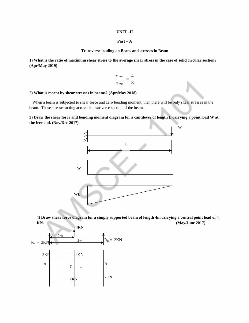
3) Draw the shear force and bending moment diagram for a cantilever of length L carrying a point load W at
the free end. (Nov/Dec 2017)
4) Draw shear force diagram for a simply supported beam of length 4m carrying a central point load of 4
KN. (May/June 2017)
C B A
RA = 2KN RB = 2KN
2KN 2KN
2KN 2KN
4KN
4m
2m
+
-
W
L
W
WL
A BR R 4KN
A B
B
M 0 4R 4KN 2
4 2R 2KN
4
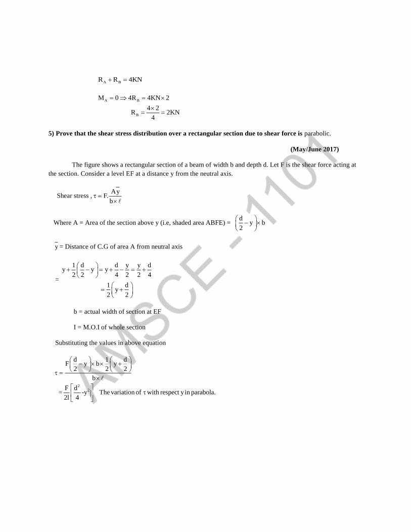
5) Prove that the shear stress distribution over a rectangular section due to shear force is parabolic.
(May/June 2017)
The figure shows a rectangular section of a beam of width b and depth d. Let F is the shear force acting at
the section. Consider a level EF at a distance y from the neutral axis.
Shear stress ,Ay
F.b
Where A = Area of the section above y (i.e, shaded area ABFE) = d
y b2
y = Distance of C.G of area A from neutral axis
=
1 d d y y dy y y
2 2 4 2 2 4
1 dy
2 2
b = actual width of section at EF
I = M.O.I of whole section
Substituting the values in above equation
2
2
d 1 dF y b y
2 2 2
b
F d= -y The variation of with respect yin parabola.
2l 4

6) Draw the shear force diagram and bending moment diagram for the cantilever beam carriers uniformly
varying load of zero initially at the freed end and w KN/m at the fixed end.
[Nov /Dec 2016]
SFD:
2x x xSF at XX
2 2
x 0 SF at B 0
x SF at A2
B
A x
X (N/m)
X
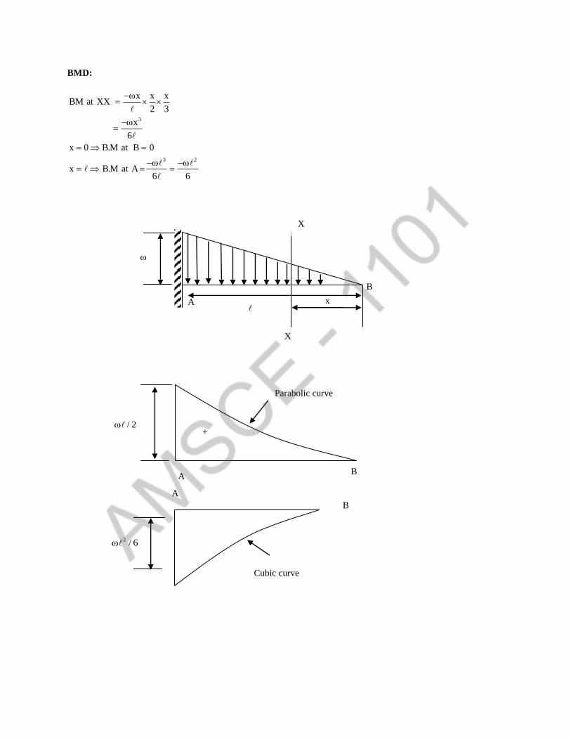
BMD:
3
3 2
x x xBM at XX
2 3
x
6
x 0 B.M at B 0
x B.M at A6 6
B A
/ 2
Parabolic curve
+
B
A
2 / 6
Cubic curve
B
A x
X
X
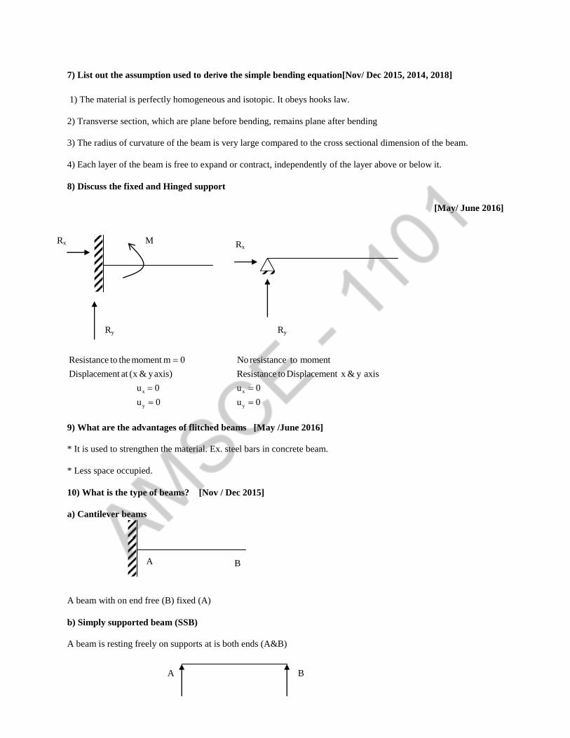
7) List out the assumption used to derive the simple bending equation[Nov/ Dec 2015, 2014, 2018]
1) The material is perfectly homogeneous and isotopic. It obeys hooks law.
2) Transverse section, which are plane before bending, remains plane after bending
3) The radius of curvature of the beam is very large compared to the cross sectional dimension of the beam.
4) Each layer of the beam is free to expand or contract, independently of the layer above or below it.
8) Discuss the fixed and Hinged support
[May/ June 2016]
x
y
Resistance to the moment m 0
Displacement at (x & yaxis)
u 0
u 0
x
y
No resistance to moment
Resistance to Displacement x & y axis
u 0
u 0
9) What are the advantages of flitched beams [May /June 2016]
* It is used to strengthen the material. Ex. steel bars in concrete beam.
* Less space occupied.
10) What is the type of beams? [Nov / Dec 2015]
a) Cantilever beams
A beam with on end free (B) fixed (A)
b) Simply supported beam (SSB)
A beam is resting freely on supports at is both ends (A&B)
Ry
u
Rx M
Ry
Rx
A B
A B

C) Overhanging beam
One or both the end portion beyond the support
d) Fixed beam
A beam whose both ends are fixed
e) Continuous beam:
A beam which has more than two supports
11) Define a) sheer force b) bending moment [Apr /May 2015]
Sheer Force:
Algebraic sum of the forces acting on either right side or left side of the section
Bending moment
Algebraic sum of moment due to all forces acting on either right or left of the section
A B A
C
C
A B A
D
A B
A B C D

12) What is neutral axis of a beam under simple bending? [Apr/ May 2015]
The line of intersection of the neutral layer, with any normal cross section of a beam is known as neutral
axis of that section.
To locate the neutral axis of a section, first find out the centroid of the section and then draw a line passing
through this centroid and normal to the plane of bending. This line will be the neutral axis of the section.
13) Draw SFD for a 6m cantilever beam carrying a clockwise moment of 6KNm at free end [Nov/ Dec 2014]
No vertical force. So shear force is zero
14) What are flitched beams? (Nov/Dec 2017)
A beam which is constructed by two different materials is known as flitched or composite beam. It is used
to reinforced the material and reduced the cost.
15) Mention the assumption made in the theory of simple bending?
Assumption made in the theory of pure Bending
The material of the beam is homogeneous and isotropic.
The value of young’s modulus of elasticity is same in tension and compression
The transverse section which were plane before bending remain plane after bending also
The beam is initially straight and all longitudinal filaments bend into circular arcs with a common centre of
curvature.
The radius of curvature is large as compared to the dimension of the cross section
Each layer of the beam is free to expand or contract, independently of the layer above or below it.
16) Define point of contra flexure? In which beam it occurs? (Apr/May 2018) (Nov/Dec 2018) (Apr/May 2019)
The point where the bending moments change its sign or zero is called point contra flexure. It occurs in
overcharging beam.
17) Write the theory of simple bending equation?
M F E
I Y R
M – Maximum bending moments
I – Moments of inertia
F – Maximum stress induced
Y – Distance from the neutral axis
6KNm A B
A B SFD

E – Young’s modules
R – Radius of curvature
18) Define beam?
BEAM is a structural member which is support along the length and subjected to external loads acting
transversely (i.e) perpendicular to the centre line of the beam.
19) What is mean by transverse loading on beam?
If a load is acting on the beam perpendicular to the axis of the beam then it is called transverse loading.
20) What is mean by positive or sagging BM?
BM is said to positive if moment on left side of beam is clockwise or right side of the beam is counter
clockwise.
21) What is mean by negative or hogging BM?
BM is said to negative if moment on left side of beam is counter clockwise or right side of the beam is
clockwise.
22) When will bending moments is maximum?
BM will be maximum, when shear force change its sign.
23) What are the types of loads?
Concentrated load or point load
Uniform distributed load
Uniform varying load.
24) Define “Section Modulus”
It is the ratio of moment of inertia to the distance of plane from the neutral axis.
25) What is moment of resistance of the section?
It is product of the section modules and stress at that section
26) Define shear stress distribution
The variation of shear stress along the depth of the beam is called shear stress distribution.
27) Sketch a) the bending stress distribution b) shear stress distribution for a beam of rectangular cross
section
a
a
b

28) A rectangular beam of 150 mm wide & 250 mm deep is subjected to a max. shear force of 30KN.
Determine i) Avg. shear stress ii) max. shear stress iii) shear stress at a distance of 25 mm above the neutral
axis
2A b d 150 250 37500mm
32
avg
2
max avg
42
3
3
4
3 22
2
i) Avgshear stress :
F 30 10q 0.8N / mm
A 37500
ii) Max shear stress :
q 1.5q 1.5 0.8 1.2N / mm
F diii)q y
2I 4
bdI
12
150 250
12
195312500mm
y 25mm
30 10 250q 25
2 195312500 4
q 1.152 N / mm

PART – B
1) Draw the shear force and bending moment diagram for the overhanging beam carrying uniformly
distributed load of 2kN/m over the entire length and a point load of 2kN as shown in fig. Locate the point of
contraflexure. (Apr/May 2019)

2) A timber beam 100mm wide and 200mm deep is to be reinforced by bolting on two steel flitches each
150mm by 12.5mm in section. Calculate the moment of resistance when flitches are attached symmetrically
at the top and bottom. Allowable stress in timber is 6 N/mm2. Es = 2× 10
5 N/mm
2 and Et = 1× 10
4 N/mm
2
(Apr/May 2019)

3) Draw a shear force and bending moment diagram for a simply supported beam of length 9m and carrying
a uniformly distributed load of 10kN/m for a distance of 6m from the left end. Also calculate the maximum
bending moment on the section. (Nov/Dec 2018)


4) A simply supported wooden beam of span 1.3m having a cross section 150mm wide by 250mm deep carries
a point load W at the centre. The permissible stresses are 7 N/mm2 in bending 1 N/mm
2 in shearing.
Calculate the safe load W. (Nov/Dec 2018)

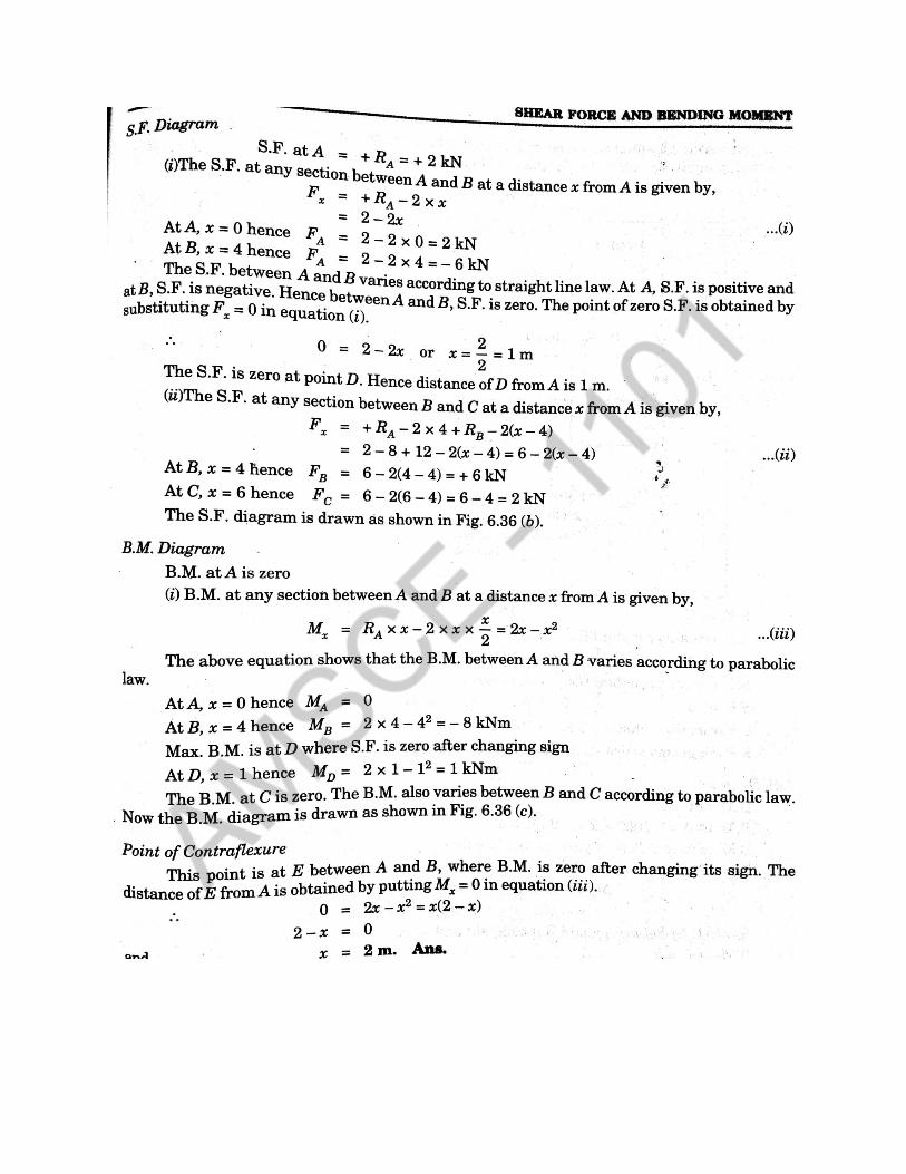
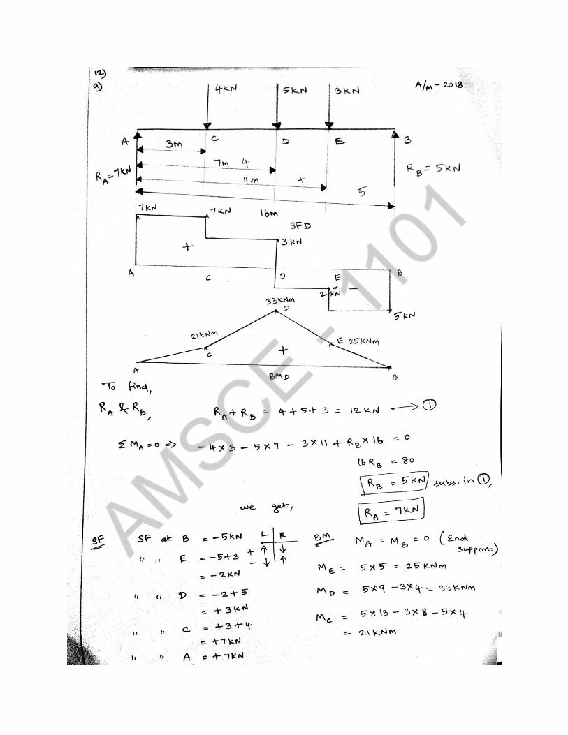
5) A simply supported beam of 16m effective span carries the concentrated loads of 4kN, 5kN and 3kN at
distances 3m, 7m and 11m respectively from the left end support. Calculate maximum shearing force and
bending moment. Draw the S.F and B.M diagrams (Apr/May 2018)

6) A timber beam of rectangular section is support a load of 50kN uniformly distributed over a span of 4.8m
when beam is simply supported. If the depth of section is to be twice the breath, and the stress in the timber
is not to exceed 7 N/mm2, find the dimensions of the cross section. (Apr/May 2018)
2
2 2 3
2
3
max
3
50
4.8
2
7 /
(2b) 2
6 6 3
know that,
SSB with UDL, M=8 8
50 10 4.8M= 30000 30000000
8
M=
230000000=7 b=185.94 186mm
3
d=2b=372mm
b
W kN
l m
d b
N mm
bd b bZ
we
wl Wl
x xNm Nmm
xZ
bx
7) A cantilever of length 2m carries a uniformly distributed load of 2kN/m length over the whole length and a
point load of 3kN at the free end. Draw the S.F and B.M diagram for the cantilever. (Nov/Dec 2017)


8) A beam is simply supported and carries a uniformly distributed load of 40kN/m run over the whole span.
The section of the beam is rectangular having depth as 500mm. If the maximum stress in the material of the
beam is 120 N/mm2 and moment of inertia of the section is 7x10
8mm
4, find the span of the beam. (Nov/Dec
2017)
2
max
8 4
max
max
85 3
max
2 22 2
max
2 5
40 / 40000 /
500
120 /
7 10
500250
2 2
7 1028 10
250
400005000 5000 1000
8 8
5000 1000 120 28 10 l=8.197mm 8.2mm
w kN m N m
d mm
N mm
I x mm
IZ
y
dy mm
I xZ x mm
y
wl xlM l Nm l x Nmm
M xZ
l x x x
9) Draw shear force diagram and bending moment diagram for the beam given in fig.2 (May/June 2017)
A
5KN/m 10KN/m
2m 2m 3m
D C B

Solution.
First calculate the reactions RA and RB
Taking moments of all forces about A, we get
B
B
3 2R 7 10 3 5 2 3 2 45 60 105
2 2
105R 15kN
7
and RA = Total load on beam-RB
= (10 x 3 + 5 x 2) – 15 = 40 – 15 = 25 kN
S.F Diagram
The shear force At A is + 25kN
The shear force at C = RA – 3 x 10 = +25 – 30 = -5kN

The shear force varies between A and C by a straight line law.
The shear force between C and D is constant and equal to -5kN
The shear force at B is -15kN
The shear force between D and B varies by a straight line law.
The shear force diagram is drawn as shown in Fig.2(b)
The shear force is zero at point E between A and C . Let us find the location of E from A. Let the point E
at a be distance x from A.
The shear force at E = RA – 10 x x= 25 – 10x
But shear force at E = 0
∴ 25 – 10x = 0 or 10x = 25
Or 25
x 2.5m10
B.M.Diagram
B.M.. at A is zero
B.M. at B is zero
B.M. at C, Mc = RA x 3 – 10 x 3 x 3
2= 25 x 3 – 45 = 75 – 45 = 30 kNm
At E, x = 2.5 and hence
B.M. at E, ME = RA x 2.5 – 10 x 2.5 x 2.5
2 = 25 x – 5 x 6.25
= 62.5 – 31.25 = 31.25 kNm
B.M. at D, MD = 25(3+2) – 10 x 3 x 3
22
= 125 – 105 = 20 kNm
The B.M. between AC and between BD varies according to parabolic law. But B.M. between C and D varies
according to straight line law. Now the bending moment diagram is drawn as shown in Fig.2.(c)
10) A beam of square section is used as a beam with one diagonal horizontal. The beam is subjected to a shear
force F, at a section. Find the maximum shear in the cross section of the beam and draw shear stress
distribution diagram for the section.
Solution:
Given : A square section with its diagonal horizontal.
The beam with horizontal diagonal is shown in Fig.2.(a)

Let 2b = Diagonal of the square, and
F = shear force at the section
Now consider the shaded strip AJK at a distance x from the corner A. From the geometry of the figure, we find that
length JK = 2x
∴ Area of AJK, 21A 2x.x x
2
and 2x
y b3
we know that moment of inertia of the section ABCD about the neutral axis,
3 42b b b
I 212 3
and shearing stress at any point,
2
4
2
4
2xx b
Ay 3F F Here b JK 2x)
Ib b2x
3
F3bx 2x .... i
2b
We also know that when x = 0, τ = 0 and when x = b, then
mean2
F F
Area2b
Now for maximum shear stress, differentiating the equation (i) and equating it to zero

2
4
d d F3bx 2x 0
dx dx 2b
3b3b 4x 0 or x
4
Substituting this value of x in equation (i),
2 2
max 4 4
mean2
F 3b 3b F 9b3b 2
4 4 82b 2b
9 F 9 F 9
8 8 Area 82b
Now complete the shear stress distribution diagram as shown in Fig.2(b)
11) A simply supported beam AB of length 5m carries point loads of 8 KN, 10 KN and 15 KN at 1.5 m, 2.50m
and 4.0 m respectively from the left hand support. Draw the sheer force diagram and bending moment
diagram. (Nov / Dec 2016)
A C D E B
4 m
2.5 m
1.5 m
RA=19.42KN
15 KN 10 KN 8 KN
5 m
RB=13.6 KN
_
+ 1.4 KN
A C D E B
13.6 KN
11.4 KN
19.4 KN

To Find Reaction RA and RB,
B
A B
A
R R 8 10 15 33
R R 33 KN ......1
A B
B
B
A
M 0 R 5 15 4 10 2.5 8 1.5 0
5R 97
R 19.4KNsubstitutein1
R 13.6KN
SFD BMD
SF at B 13.6 KN
SF at E 13.6 15 1.4KN
SF at D 13.6 15 10 11.4KN
SF at C 13.6 15 10 8 19.4 KN
SF at A 19.4KN
A B
E
D
SSB at supports M M 0
M 13.6 1 13.6KNm
M 13.6 2.5 15 1.5 11.5 KNm
12) A cantilever beam AB of length 2m carries a uniformly distributed load of 12 KN/m over entire length.
Find the shear stress and bending stress, if the size of the beam is 230mm 300 mm. [5 mark]
[Nov/ Dec 2016]
Bending stress: Shear stress:
0.1 KN
11.5 KN
13.6 KN
A C D E B
+
12 KN/m
A B
2 m
300
230

b
2
2
3 3
M
y I
M2
12 2M 24 KNm
2
bd 230 300I
12 12
max avg
avg
3
2
avg
2
max
F 24 KN
3
2
F
bd
24 10
230 300
0.347 N / mm
0.52 N / mm
4
b
3 2
2
b
I 517500000mm
y 150mm
My
I
24 10 10 150
517500000
6.96 N / mm
13) Construct the SFD & BMD for the beam as shown in fig (6 mark)
[Nov/ Dec 2016]
2
max 052 N / mm
2
avg 0.347 N / mm
2
b 6.96N / mm
2
b 6.96N / mm
300
230
25 KN
D
B A E
C

12.5 KN 12.5 KN
12.5 KN
A C B
SFD
12.5 KN
25 KN
D
18.75 KNm
A C B
0.5 m
RA RB
A C B
25 KN
37.5 K.N
RA = 12.5 KN RB =12.5 KN
37.5 KN
D
A C B
25 KN
A B
A
B
B
A
R R 25KN ...1
M 0
4R 25 2
R 12.5KN
R 12.5KN
SFD
S.F at B 12.5 KN
S.F at C 12.5 25 KN
12.5 KN
S.F at A 12.5 KN
A B
C
max
BMD
m m 0
m 12.5 2 25KNm
SF 0 at C BM 25 KNm
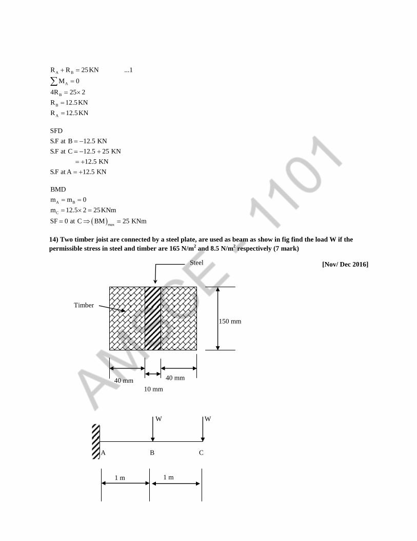
14) Two timber joist are connected by a steel plate, are used as beam as show in fig find the load W if the
permissible stress in steel and timber are 165 N/m2 and 8.5 N/m
2 respectively (7 mark)
[Nov/ Dec 2016]
W W
1 m 1 m
A B C
10 mm
40 mm 40 mm
Timber
150 mm
Steel

2 2
s w
2 2
w
3 3
2 2
s
3
w w w
3
6
s s s
6
w s
6
3
165 N / mm 8.5 N / mm
bd 80 150Z
6 6
300 10 mm
bd 10 150Z
6 6
37500 mm
m Z
8.5 300 10
2.55 10 N mm
m Z
165 37500
6.18 10 N mm
m m m
3w m 8.7 10 N mm
W m / 3000 2.91 10 N
W 2.91
A B C
SFD
+
3w
A B C
_
BMD

15) Draw SRD & BDM and indicates the salient feature of beam loaded in fig
[May / June 2016]
A B
A
R & R :
m 0
A B
B
B
B
A
R R 10 2 7 15 105KN ...1
7R 7 5 7 15 8.5 10 2 1 0
2
7R 352.5 KN
R 50.36 KN sub in 1
R 54.64 KN
RB = 50.36 KN
RA = 54.64 KN
C A B C
x
X 15 KN 10 KN/m
1.5 m 7 m 2 m
C -A -B D
34.64 KN
15 KN
SFD
20 KN
35.36 KN
D
-B -A
C
22.5 KNm
40.01 KNm 19.98 KNm

SFD
SF at D 15KN
SF at B 15 50.36 35.64
SF at A 15 50.36 10 7 34.64 KN
SF at A 34.64 54.64 20 KN
SF at C 20 10 2 0
BMD
BM at D 0
BM at B 15 1.5 22.5 KN
7BM at A 15 8.5 50.36 7 10 7
2
19.98 KNm
9BM at C 15 10.5 50.36 9 10 9 54.64 2
2
0.02 0
SF at XX 15 50.36 10 x 1.5
BM at XX 15x 50.6 x 1.5 10 x 1.5 x 1.5 ...2
SF at XX 0
15 50.36 10 x 1.5 0
10 x 1.5 35.36
x 1.5 3.536
x 5.036m sub in equation 2
B.M at x 5.036 40.01 KNm
16) Find the dimensions of a timber joist, spam 4m to carry a brickwork is 20 KN/m3. Permissible bending
stress in timber is 10N/mm2. The depth of the joist twice the width (8)
[May/ June 2016]
3
2
b max
4m
t 230 mm 0.23m
h 3m
20 KN / m
10N / mm
d 2b
Wt of bricks wall (W) = t h
SSB with UDL, = 20 0.23 3 4 55.2KN

2
6
33 4
4 3
3
b
36
63
55.2 4M
8 8 8
M 27.6 KNm 27.6 10 Nmm
b 2bbd 8bI
12 12 12
d 2by b
2 2
I 8b 1 8bsection modulus Z
y 12 b 12
8bM Z 10
12
8b10 27.6 10
12
27.6 10 12b
10 8
b 160.57 mm
d 2b 321.14 mm
17) Draw the sheer force & bending moment diagram for a simply supported beam of length 8m and carrying
a UDL of 10KN/m for a distance of 4m as shown in fig (16)
[Nov/ Dec 2015]
10 KN/m
RB = 15 KN RA = 25 KN
A C D B
3 m 4 m 1 m
8 m
15KN
25KN
A C D B
SFD
+
_
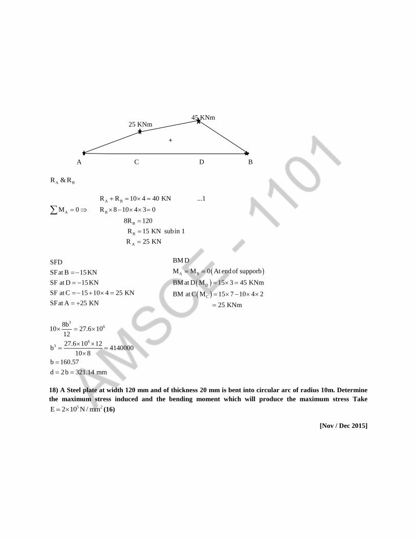
A BR & R
A B
A B
B
B
A
R R 10 4 40 KN ...1
M 0 R 8 10 4 3 0
8R 120
R 15 KN subin 1
R 25 KN
SFD
SFat B 15KN
SF at D 15KN
SF at C 15 10 4 25 KN
SFat A 25 KN
A B
D
C
BM D
M M 0 At end of supporb
BM at D M 15 3 45 KNm
BM at C M 15 7 10 4 2
25 KNm
36
63
8b10 27.6 10
12
27.6 10 12b 4140000
10 8
b 160.57
d 2b 321.14 mm
18) A Steel plate at width 120 mm and of thickness 20 mm is bent into circular arc of radius 10m. Determine
the maximum stress induced and the bending moment which will produce the maximum stress Take 5 2E 2 10 N / mm (16)
[Nov / Dec 2015]
45 KNm 25 KNm
+
A C D B

3 2
34
max
b
b max
5 22
b 3
5
3
6
b 120mm t 20mm R 10m
E 2 10 N / mm
btI 80000mm
12
t 20y 10mm
2 2
M E
I y R
Ey
R
2 10 1010 200 N / mm
10 10
M E
I R
E 2 10M I 80000
R 10 10
M 1.6 10 Nmm
19) An overhanging beam ABC of length 7 m is simply supported at A & B over a span of 5m and the portion
overhangs by 2m. Draw the shearing force & bending moments diagram and determine the point of contra
flexure if it is subjected to UDL of 3 KN/ m over the portion AB and a concentrated load of 8 KN at C.(16)
[Apr/ May 2015]
A BR & R
_
+
A B C
8 KN
SFD 35.36 KN
+
RB = 18.7 KN RA = 4.3KN
A B C
x
X 8 KN 3 KN/m
2m 5 m
7 m

A B
A B
B
B
A
R R 3 5 8 23 KN ...1
5M 0 R 5 3 5 8 7 0
2
5R 93.5
R 18.7 KN subin 1
R 4.3 KN
SFD
SF at C 8 KN
SF at B 8 18.7 10.7 KN
SF at A 10.7 3 5
4.3 KN
C
B
A
BMD
M 4.3 7 3 5 4.5 18.7 2
M 8 2 16KNm
5M 8 7 18.7 5 3 5 0
2
Assume
XX section at a distance of x from end B,
max
2
2
SF at XX 8KN 18.7 3Xx 0
3Xx 10.7
x 3.57 m
xBM at XX 8 x 2 18.7 x 3 x
2
BM 3.08 KNm
x 3.57 B.M at XX 0
8x 16 18.7x 1.5x 0
1.5x 10.7x 16 0
x 5m or x 2.13m
20) Draw SFD & BMD and find the max bending moment for the beam given in fig
[Nov/ Dec 2014]
3.08 KNm
C A
16 KNm
B
_

RA & RE
A E
A E
E
E
A
1R R 20 2 6 26 KN ...1
2
1 1M 0 R 8 2 6 2 2 2 20 2 0
2 3
8R 68
R 8.5KN sub in1
R 17.5 KN
A B C D E
17 KNm
30 KNm
35 KNm
+
8.5 KN
2.5 KN
A B C D E
_
17.5 KN
8.5 KN
17.5 KN
+
SFD
RE= 8.5 KN
A B C D E
2 m 2 m 2 m 2 m
1/3 2/3
RA= 17.5 KN
6 KN m
20 KN

SFD
SF at E 8.5 KN
SF at D 8.5 KN
1SF at C 8.5 2 6 2.5 KN
2
SF at B 2.5 20 17.5KN
SF at A 17.5 KN
A E
max
max
BMD
M M 0
B.M at D 8.5 2 17 KNm
1 1B.M at C 8.5 4 2 6 2
2 3
30KNm
1 1B.M at B 8.5 6 2 6 2 2
2 2
35KNm
SF 0 BM
SF 0 at point B B.M at B 35KNm
21) Three beams here the same length allowable stress and the same bending moment. The cross section of
the beams are a square, a rectangular with depth twice the width and a circle. Find the ratio of weight of
circular and the rectangular beam with respect to the square beam (16)
[Apr / May 2015]
Since all three beams here the same σ & M the modules of section of the three beams must be equal
2
1
2
3
1
Square beams
bdZ
6
a a
6
aZ ...1
6
2
2
2
22
2
Rectangular beam
bdZ
6
b 2b
6
4b 2Z b ...2
6 3
3
3
Circular beam
z d ...332
Equating 1 & 2
d
d= disc of
circular beam
A= side of
square beam
a
a
2b
b
Rectangular
beam
b= Width
2b=Depth

3 2
3 2
3 3
a 2b
b 3
2a 6 b
3
a 4b
b 0.63a ...4
33
3 3
Equating1& 3
ad
6 32
a 6 d32
d 1.19a ...5
Weight of all the beams are proportional to the c/s area of their section,
Weight of Squarebeam Area of squarebeam
Weight of rec tangular beam Area of rectangular beam
2 2
2 2
2 2
22
a a 1
0.792b 2 0.63a
Weight of Square beam Area of square beam
Weight of circular beam Area of Circular beam
a a
d 1.19a4 4
1
1.12
22) Prove that the ratio of depth to width of the strongest beam that can be cut from a circular log of
diameter d is 1.414. Hence calculate the depth and width of the strongest beam that can be cut of a cylindrical
log of wood whose diameter is 300mm.
Diameter of circular log of wood = D
b = breadth of rectangular beam
d = depth of rectangular beam
2section bd
Z ...1modulus 6
From geometry of the fig ,
d
b
D

2 2 2
2 2 2
b d D
d D b ..2 substitutingequ1
2
2 2
3
b D bZ
6
bD b
6
For strongest section, Differentiate the above equation and equate it to zero,
2 3 2
2 2
2 2
2 2
2 22 2
dz d bD b D 3b
db db 6 6
D 3b0
6
D 3b 0
3b D
Db ...2 subtituting in equa1
3
D 2Dd D
3 3
2d D ..4
3
Equ 4 Equ 3
2D
d 2 33D
Db 3 D
3
d2 1.414 Henceit is proved
b
PART-C
23) A water main of 500mm internal diameter and 20mm thick is full. The water main is of cast iron and is
supported at two points 10m apart. Find the maximum stress in the metal. The cast iron and water weigh
72000 N/m3 and 10000 N/m
3 respectively. (May 2017 – 15 Marks)
Given:
Internal diameter, Di = 500 mm = 0.5 m
Thickness of pipe, t = 20 mm
∴ outer dia, D0 = Di + 2 x t = 500 + 2 x 20
= 540 mm = 0.54 m
Weight density of cast iron = 72000 N/m3
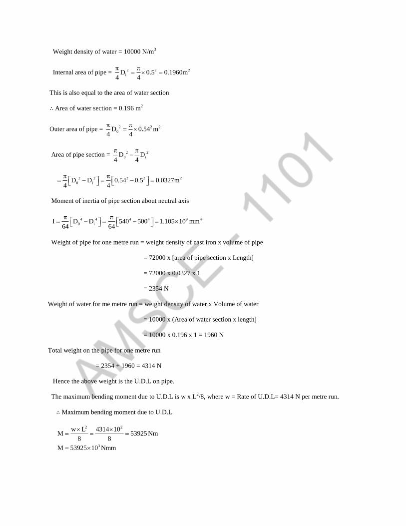
Weight density of water = 10000 N/m3
Internal area of pipe = 2 2 2
iD 0.5 0.1960m4 4
This is also equal to the area of water section
∴ Area of water section = 0.196 m2
Outer area of pipe = 2 2 2
0D 0.54 m4 4
Area of pipe section = 2 2
0 iD D4 4
2 2 2 2 2
0 iD D 0.54 0.5 0.0327m4 4
Moment of inertia of pipe section about neutral axis
4 4 4 4 9 4
0 iI D D 540 500 1.105 10 mm64 64
Weight of pipe for one metre run = weight density of cast iron x volume of pipe
= 72000 x [area of pipe section x Length]
= 72000 x 0.0327 x 1
= 2354 N
Weight of water for me metre run = weight density of water x Volume of water
= 10000 x (Area of water section x length]
= 10000 x 0.196 x 1 = 1960 N
Total weight on the pipe for one metre run
= 2354 + 1960 = 4314 N
Hence the above weight is the U.D.L on pipe.
The maximum bending moment due to U.D.L is w x L2/8, where w = Rate of U.D.L= 4314 N per metre run.
∴ Maximum bending moment due to U.D.L
2 2
3
w L 4314 10M 53925 Nm
8 8
M 53925 10 Nmm

Now using M
I y
M
yI
The stress is maximum when y is maximum
0D 540y 270mm
2 2
ymax = 270 mm
∴ maximum stress max max
My
I
3
9
2
53925 10270
1.105 10
13.18 N / mm