TORSIONAL STRESSES INTHE TRANSVERSE FILLET WELD TUBULARJ'OINTS · TORSIONAL STRESSES INTHE...
7
Mathematical & Computational Applicatiol1s, Vol. 1, No.1, pp. 29-35, 1996 © Association for ScientificResearcb TORSIONAL STRESSES IN THE TRANSVERSE FILLET WELD TUBULARJ'OINTS * Sakarya University, Mechanical Engineering Department, Adapazarl-Tiirkiye ** Gaziosmanpa~a University, Tokat-Tiirkiye Torsional stresses, 'tre and tel , in tbe transverse fillet tubular weld joint subjected to torsional load have been analyzed by the finite element method using triangular and quadrilateral izoparametric axisymmetric fourier type torus finite elements. There is an axisymmetry with respect to geometry and material properties but no axisymmetry with respect to the loading. With respect to material properties, two kinds of joints are considered in the study. One consists of steel tubes and steel weld material, the other steel tubes and brass weld material. All of the materials used are assumed linear-elastic. Changing the torsional stresses, along the weld legs and the weld throat, are plotted indimensionless coordinates. Welding process is extensively used in manufacturing today. One of the most important problems in weld joints is to determine the stresses in the welds. In application, transverse fillet weld tubular joint is one of the most common types of lap joints. Gurney [6] have analyzed diffusion-bonded lap joints by the finite element method (FEM). Tekelioglu at all [11] and Giinay at all [7] have analyzed transverse fillet weld double and single lap joints by FEM, respectively. G-. ~~ p. >1 .:':':::" A hk- b a Analysis of transverse fillet weld tubular joint under the torsion has the similar structure of the problems of adhesive-bonded tubular lap joints subjected to torsion [1, 5] and axisymmetric bodies under torsion [12]. However, unlike the flat-lap joints, there is very limited number of theoretical/numerical studies on the transverse fillet weld tubular joints,
Transcript of TORSIONAL STRESSES INTHE TRANSVERSE FILLET WELD TUBULARJ'OINTS · TORSIONAL STRESSES INTHE...

Mathematical & Computational Applicatiol1s, Vol. 1, No.1, pp. 29-35, 1996© Association for Scientific Researcb
TORSIONAL STRESSES IN THE TRANSVERSE FILLETWELD TUBULARJ'OINTS
* Sakarya University, Mechanical Engineering Department, Adapazarl-Tiirkiye** Gaziosmanpa~a University, Tokat-Tiirkiye
Torsional stresses, 'tre and tel , in tbe transverse fillet tubular weld joint subjected to torsional loadhave been analyzed by the finite element method using triangular and quadrilateral izoparametricaxisymmetric fourier type torus finite elements. There is an axisymmetry with respect to geometryand material properties but no axisymmetry with respect to the loading. With respect to materialproperties, two kinds of joints are considered in the study. One consists of steel tubes and steelweld material, the other steel tubes and brass weld material. All of the materials used are assumedlinear-elastic. Changing the torsional stresses, along the weld legs and the weld throat, are plottedin dimensionless coordinates.
Welding process is extensively used in manufacturing today. One of the most importantproblems in weld joints is to determine the stresses in the welds.
In application, transverse fillet weld tubular joint is one of the most common types of lapjoints. Gurney [6] have analyzed diffusion-bonded lap joints by the finite element method(FEM). Tekelioglu at all [11] and Giinay at all [7] have analyzed transverse fillet welddouble and single lap joints by FEM, respectively.
G-.~~
p.
>1.:':':::"
A hk-b a
Analysis of transverse fillet weld tubular joint under the torsion has the similar structureof the problems of adhesive-bonded tubular lap joints subjected to torsion [1, 5] andaxisymmetric bodies under torsion [12]. However, unlike the flat-lap joints, there is verylimited number of theoretical/numerical studies on the transverse fillet weld tubular joints,

to the authors' knowledge. In this work, we have analyzed the stresses in the joint by thefinite element method using the Lusas software.
The weld joint analyzed is shown in the Fig.(l). In the figure, inner welded tube, outerwelded tube and weld region are labeled as 1,2 and 3 , respectively. The inner and outerradius of the inner welded tube is a and b, respectively. The inner and outer radius of theouter welded tube is b and c, respectively. In the weld region, the radial legs length andlongitudinal leg lengths are equal to each other and h(= c - b). The length of each weldedtube is .e. The thicknesses of tubes are assumed to be equal to each other. Thereforec-b=b-a or b=(a+c)/2.
For the finite element mode~ the upper part of the axisymmetric problem given in theFig. (1) is shown in the Fig. (2). There is an axisymmetry with respect to geometry andmaterial properties but no axisymmetry with respect to the loading.
1< eJ'~
e>1 z', x.
G>-
hI
_c b L a _
Figure 2. The upper part of the plane section of the jointalong its symmetry axis and coordinates.
When the joint geometry is considered, it is easily seen that the problem has anaxisymmetric configuration. Let in the cylindrical coordinates, radial direction, hoopdirection and longituditional direction be r, e and z, respectively. The displacements withrespect to those axes are U, v and w, respectively. In an axisymmetric body's torsionproblem, using the semi-inverse method, the u and w displacements can be assumed aszero. It is pOSSlbleto show that the solution based on the these assuming satisfies theelasticity equations. Hence, the solution based on the assumption is an true solution.Thus, in the strain-displacement equations by taking u=w=O, because of the axisymmetry,displacement v is independent from e, and we have [10]
&v v &vYre= --- , Y'1Jj=-Or r 8z"Fromthe Hook's law and from Eq. (1) it is seen that all of the stresses are zero except treandt'1Jj .

l(0.0)
1(-1,-1) -----.-
Figure 3. Cross section of axisymmetric ring elementwith 4-nodes and natural coordinates.
Shape functions vector is expressed in terms of variables vector L and constants vector Qas [8],
1 1 1
{Nt N4}={11 -1 1 1 -
N2 N3 ~ 11 ~ll}--1 --1 1
~N=LQ (2)4
11 -1 1 -
By taking tangential displacement as V=[VI V2 V3 v4f , the displacement of any point onthe elements is v = Nv. By considering the strain-displacement equations and Eq. (2)together, we have
Ov v a 1 aLYre=---=-(LQv)--LQv =-Qv-ar r ar r ar
av a 8LYze= - = -(LQv) = -Qvaz 8z az
1-LQvr
[8L 1 1
E={Y re} and B= &- -;.-L ~Q
Y ze l ~~J
T,-e=GreYreT8z=GezYez
IGre 0 ID=I' 0 Gezl

ke == 21tJBTDBrdAe
Geometric PropertiesDimensions used are given in the Tab. (1).
Notation Dimension fmmlh(==c-b) 5
a 3h =--=15 --b 4h = 20c 5h ==25.e 8h = 40
Material PropertiesMaterials of the joints are given in Tab. (2). Properties of materials are given in Tab. (3).
Table 2. Materials 0 the ·oints.Joint Inner tube Outer tube Weld
Joint 1 J1 Steel Steel SteelJoint 2 J2 Steel Steel Brass
In the model, left end of the joint is fixed and the torque T is applied to the right end asthe maximum value of shear stress (tez)max = 'to = 1 MPa. Because of nature of the :finiteelements used, the load can not be applied as torque, instead, a couple which producestorque is applied, perpendicular to the sheet surface, to the right end of the joint at thepoints which has a distance equal to outer radius of the inner tube, r=b. Hence, theapplied force giving the shear stress 'to = 1 is calculated as
At the left end of the outer tube (z= -f), the tangential displacements v are taken as equalto zero (Fig. 2). There is no any support in the Fig. (4), because of tangential direction eis in the direction perpendicular to tbis sheet surface. Fourier type torus :finite elementsare used in the solution. The tubes are subdivided into quadrilateral torus :finiteelements
and the weld region is subdivided into triangular torus finite elements. The finite elementmesh used in the solution is given in the Fig. (4).
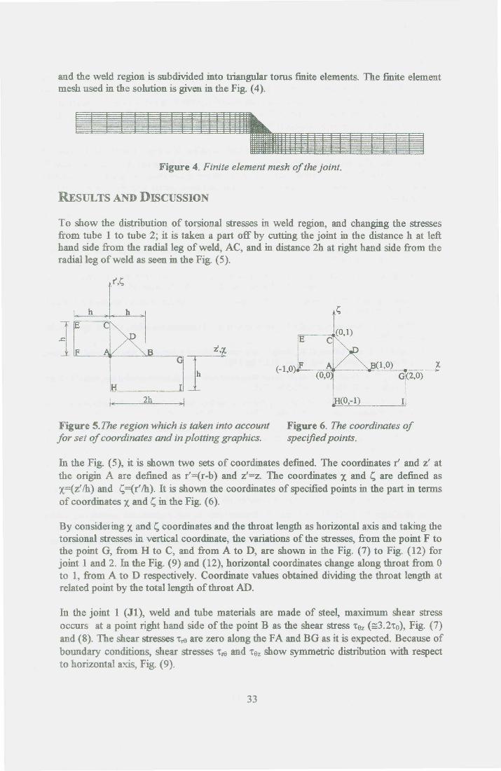
To show the distnbution of torsional stresses in weld region, and changing the stressesfrom tube 1 to tube 2; it is taken a part off by cutting the joint in the distance h at lefthand side from the radial leg of weld, AC, and in distance 2h at right hand side from theradial leg of weld as seen in the Fig. (5).
IEi,X i
H IiI", 2h •.I
Figure 5.The region which is taken into accountfor set of coordinates and in plotting graphics.
Figure 6. The coordinates ofspecified points.
In the Fig. (5), it is shown two sets of coordinates defined. The coordinates r' and z' atthe origin A are defined as r'=(r-b) and z'=z. The coordinates X and l; are defined asX=(z Ih) and l;=(r' Ih). It is shown the coordinates of specified points in the part in termsof coordinates X and l; in the Fig. (6).
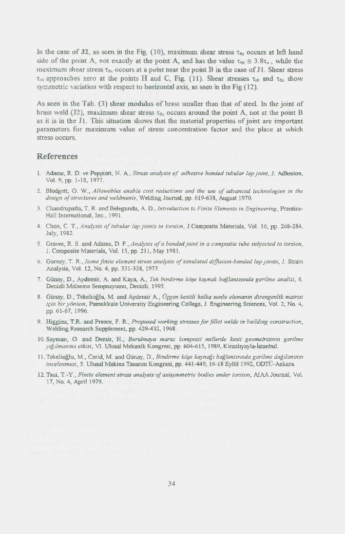
By consideting X and l; coordinates and the throat length as horizontal axis and taking thetorsional stresses in vertical coordinate, the variations of the stresses, from the point F tothe point G, from H to C, and from A to D, are shown in the Fig. (7) to Fig. (12) forjoint 1 and 2. In the Fig. (9) and (12), horizontal coordinates change along throat from 0to 1, from A to D respectively. Coordinate values obtained dividing the throat length atrelated point by the total length of throat AD.
In the joint 1 (Jl), weld and tube materials are made of steel, maximum shear stressoccurs at a point right hand side of the point B as the shear stress 'tez (=3.2'to), Fig. (7)and (8). The shear stresses 'tre are zero along the FA and BG as it is expected. Because ofboundary conditions, shear stresses 1'reand 1'9zshow symmetric distribution with respectto horizontal axis, Fig. (9).
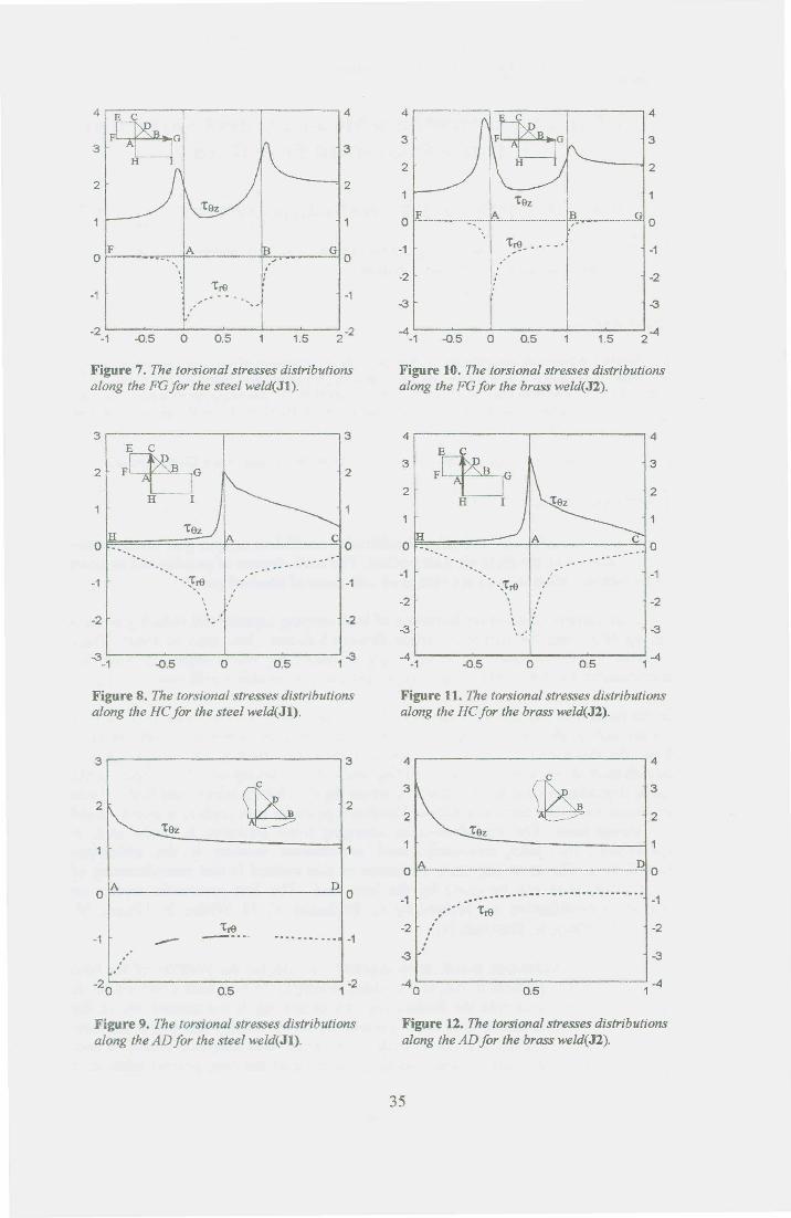
In the case of J2, as seen in the Fig. (10), maximum shear stress "Cez occurs at left handside of the point A, not exactly at the point A, and has the value 't'ez == 3.8'to, while themaximum shear stress 'tez occurs at a point near the point B in the case of JI, Shear stress1'1'9 approaches zero at the points H and C, Fig. (ll). Shear stresses "Crt) and "Cez showsymmetric variation with respect to horiZontal axis, as seen in the Fig (12).
As seen in the Tab. (3) shear modulus of buss smaller than that of steel. In the joint ofbrass weld (12), maximum shear stress 'fez occurs around the point A, not at the point Bas it is in the J1. This situation shows that the material properties of joint are importantparameters for maximum value of stress concentration factor and the place at whichstress occurs.
1. Adams, R. D. ve Peppiatt, N. A, Stress analysis of adhesive bonded tubular lap joint, J. Adhesion,Vol. 9, pp. 1-18, 1977.
2. Blodgett, O. W., Allowables enable cost reductions and the use of advanced technologies in thedesign of structures and weldments, Welding Journal, pp. 619-638, August 1970.
3. Chandrupatla, T. R and Belegundu, A D., Introduction to Finite Elements in Engineering, Prentice-Hall International, Inc., 1991.
4. Chon, C. T., Analysis of tubular lap joints in torsion, J.Composite Materials, Vol. 16, pp. 268-284,July, 1982.
5. Graves, R S. and Adams, D. F., Analysis of a bonded joint in a composite tube subjected to torsion,J. Composite Materials, Vol. 15, pp. 211, :r••.1ay 1981.
6. Gurney, T. R, Some finite element stress analysis of simulated diffusion-bonded lap joints, J. StrainAnalysis, Vol. 12, No.4, pp. 331-338, 1977.
7. Giinay, D., Aydemir, A and Kaya, A, Tek bindirme k6§e kaynak baglantlSmda gerilme analizi, 6.Denizli Malzeme Sempozyumu, Denizli, 1995.
8. Giinay, D., TekeliogIu, M. and Aydemir A, Ufgen kesitli halka sonlu elemanm direngenlik matrisiifin bir yontem, Pamukkale University Engineering College, J. Engineering Sciences, Vol. 2, No.4,pp. 61-67, 1996.
9. Higgins, T.R and Preece, F. R, Proposed working stresses for fillet welds in building construction,Welding Research Supplement, pp. 429-432, 1968.
10. Sayman, O. and Demir, H., Burulmaya maruz kompozit millerde kesit geometrisinin gerilmeylgllmaszna etkisi, VI. Ulusal Mekanik Kongresi, pp. 604-615, 1989, Kirazhyayla-tstanbul.
11.Tekelioglu, M., Cerid, M. and Ganay, D., Bindirme k6§e kaynagl baglantlSmda gerilme dagllzmznmincelenmesi, 5. Ulusal Makina Tasanm Kongresi, pp. 441-449,16-18 Ey1Ul1992, ODTU-Ankara.
12. Tsui, T.- Y., Finite element stress analysis of axisymmetric bodies under torsion, AIAA Journal, Vol.17, No.4, April 1979.
4 E C
~G3 Jr--i
F A GO0
"j ··'tre ·-1 - '"' ..~ . -1, .--2 -0.5 0 0.5 1.5 2-2-1
Figure 7. The torsional stresses distributionsalong the FG for the steel weld(Jl).
Ho ....
". -.,
'..••,t
Figure 8. The torsional stresses distributionsalong the HC for the steel weld(Jl).
Figure 9. The torsional stresses distributionsalong the AD for the steel weld(Jl).
't9z
o Ii__._.~ ;.~ ~;~----- ..-.---G 0
, 'tre __ - _.,.'.
-2 -2
-3 -3
-4_1 -0.5 0 0.5 1.5 2-4
Figure 10. The torsional stresses distributionsalong the FG for the brass weld(J2).
'.···.~re
,
Figure 11. The torsional stresses distributionsalong the HC for the brass weld(J2).
---_ ..-.--_.--- .._----- ...• ' •••• -1.' 1:•••• re.,.,
Figure 12. The torsional stresses distributionsalong the AD for the brass weld(J2).