
UNIQUE BOWSPRIT ASSURES GREATER CONTROL FOR SAILING CATAMARAN · A catamaran suffers a two-fold...
7
UNIQUE BOWSPRIT assures greater The recent "small boat explosion" that is rapidly filling our lakes and coastal waters with new pleasure craft has been characterized by in- creased interest in sailing craft of all kinds, particularly the modern catamarans and trimarans that have evolved from outrigger canoes and other similar craft long used by Poly- nesians around the Pacific islands. Single-hull sailboats depend for lateral stability on either the weight of metal keels at considerable depth below the surface of the water or on broad but shallow hulls of consider- able weight. A catamaran achieves stability by means of two very nar- row, separate hulls of light weight and low resistance to motion, con- nected by a transverse superstructure above the water. This makes the overall width of the craft from a third to a half its length. Trimarans have a third ( and usually larger ) hull in the center. But in all cases the multi-hull craft, compared to a single-hull craft of the same overall length or sail area, is a far lighter and faster boat. H. S. Morton , a consult a nt to the Labora- tor y since his retirement in 1958, came to APL in 1946 as Supervi sor of the Bumble- bee Warhead Group . He received his M.E . degree from the University of Minnesota in 1913. During World War II , Colonel Mor- ton was intimately associated with both the development and the eventual world-wide use by the Allied Powers of the proximity fuze that was developed by the Laboratory. He is also the inventor of the highly suc- cessful bombing system known as Toss Bombing. Among other honors bestowed on him, Colonel Morton has received the Legion of Merit and the U .S . Navy Dis- tinguished Public Service Award , and he is an Honorary Officer of the Most Excellent Ol- der of the British Empire . March -April 1965 control for SAILING CATAMARAN H. S. Morton The forward end of the catamaran, showing details of the movable bowsprit and its relation- ship to the two hulls and the cabin. Their growing popularity stems from the fact that they provide seaworthi- ness and passenger comfort in vessels of shallow draft and much less weight. Light weight, however, has its disadvantages too, the greatest being a serious impairment of the craft's ability to "come about" promptly and positively, a maneuver that re- quires "heading up" into the wind for the purpose of changing from one "tack" to the other. Loss of positive control during any necessary maneuver is frustrating at any time, and can be dangerous under some circumstances. The use of auxiliary power to extricate the craft from a situation resulting from the inability to control it by sail alone is anath- ema to any true yachtsman. After more than a decade of ex- perience with his first 30-foot sloop- rigged catamaran, the author has designed and built a second, similar craft on which a simple modification of the bowsprit* has made an amaz- ing improvement in positive control when "coming about." -x- Bowsprit is a spar that projects ahead of the bQw of a sailing craft . 17
Transcript of UNIQUE BOWSPRIT ASSURES GREATER CONTROL FOR SAILING CATAMARAN · A catamaran suffers a two-fold...

UNIQUE BOWSPRIT assures greater
The recent "small boat explosion" that is rapidly filling our lakes and coastal waters with new pleasure craft has been characterized by increased interest in sailing craft of all kinds, particularly the modern catamarans and trimarans that have evolved from outrigger canoes and other similar craft long used by Polynesians around the Pacific islands.
Single-hull sailboats depend for lateral stability on either the weight of metal keels at considerable depth below the surface of the water or on broad but shallow hulls of considerable weight. A catamaran achieves stability by means of two very narrow, separate hulls of light weight and low resistance to motion, connected by a transverse superstructure above the water. This makes the overall width of the craft from a third to a half its length. Trimarans have a third (and usually larger ) hull in the center.
But in all cases the multi-hull craft, compared to a single-hull craft of the same overall length or sail area, is a far lighter and faster boat.
H. S . Morton , a consulta nt to the Laboratory since his retirement in 1958, came to APL in 1946 as Supervisor of the Bumblebee Warhead Group . He received his M.E. degree from the University of Minnesota in 1913. During World War II , Colonel Morton was intimately associated with both the development and the eventual world-wide use by the Allied Powers of the proximity fuze that was developed by the Laboratory. He is also the inventor of the highly successful bombing system known as Toss Bombing. Among other honors bestowed on him, Colonel Morton has received the Legion of Merit and the U .S . Navy Distinguished Public Service Award, and he is an Honorary Officer of the Most Excellent Ol-der of the British Empire .
March -April 1965
control for
SAILING CATAMARAN H. S. Morton
The forward end of the catamaran, showing details of the movable bowsprit and its relationship to the two hulls and the cabin.
Their growing popularity stems from the fact that they provide seaworthiness and passenger comfort in vessels of shallow draft and much less weight.
Light weight, however, has its disadvantages too, the greatest being a serious impairment of the craft's ability to "come about" promptly and positively, a maneuver that requires "heading up" into the wind for the purpose of changing from one "tack" to the other. Loss of positive control during any necessary maneuver is frustrating at any time, and can be dangerous under some
circumstances. The use of auxiliary power to extricate the craft from a situation resulting from the inability to control it by sail alone is anathema to any true yachtsman.
After more than a decade of experience with his first 30-foot slooprigged catamaran, the author has designed and built a second, similar craft on which a simple modification of the bowsprit* has made an amazing improvement in positive control when "coming about."
-x- Bowsprit is a spar that projects ahead of the bQw of a sailing craft .
17
The Process of "Coming About"
Before describing the nature of the unique bowsprit design that so radically improves controllability, it is necessary to point out the typical behavior of catamarans without this device. Consider a conventional sloop-rigged sailing catamaran having a single tall mast that carries a triangular main sail, and having a bowsprit whose forward end is connected to the top of the mast by a " jibstay" on which the forward edge of a triangular "jib" (a sail of YJ to ~ the area of the mainsail ) is supported ahead of the mast.
When any sailing craft with such a "fore and aft" rig is headed directly into the wirui, the sails "luff" ( i.e., flap like flags in a breeze ) and exert no driving force. The wind
C
t
W
HINGE I
can propel a sailing craft along any course except directly against (into ) the wind or within some thirty or forty degrees of the direction from which the wind is blowing.
Progress in a general direction against the wind is achieved by pursuing a zig-zag course called "tacking." The process of heading-up into the wind in order to change from one tack to another is called "coming about."
On a tack the fore-and-aft sails are set at a small angle to the longitudinal axis of the boat, and the bow is pointed at a somewhat greater angle to the wind direction so that the wind presses on the "aft" side of the sails. Although the transverse component of force on the sails exceeds the "forward" component, there is so much more resistance
• PLAN VI EW
/"
I BOWSPRIT
e ---- - -+-- B' M
I •
to lateral motion (due to the center board, or keel, or merely to extended lateral surface) than to forward motion that the boat moves forward with very little lateral drift.
In coming about, a sailing vessel uses the rudder to turn toward the wind direction, and it loses the driving force of the wind while still some I 5 to 20 degrees "off" the wind direction. It begins to lose speed, and the rudder (whose effect depends on speed ) starts to lose its effectiveness as soon as the sails begin to luff. Only the momentum of the vessel keeps it moving forward and gives the rudder some measure of control to keep it turning through this remaining 15 or 20 degrees into the wind, and an equal amount offwind on the other side, until the sails refill on the opposite "tack."
A
\ \
\ MAST \
\ JI BSTAY
\
\ HINGE
~\ ;'OWSPRI,- " CABIN --- B -~~
7"BOBSTAY -- C
A' ~HULL
A t
'rl=------------M--------+
C S BOWSPRIT ~
S
~ B' B
I e
T ------ - --- T -_e-- B'
V I R
,~' / j ~D~
o~s /0 • • ----------W-----------+
A ' I
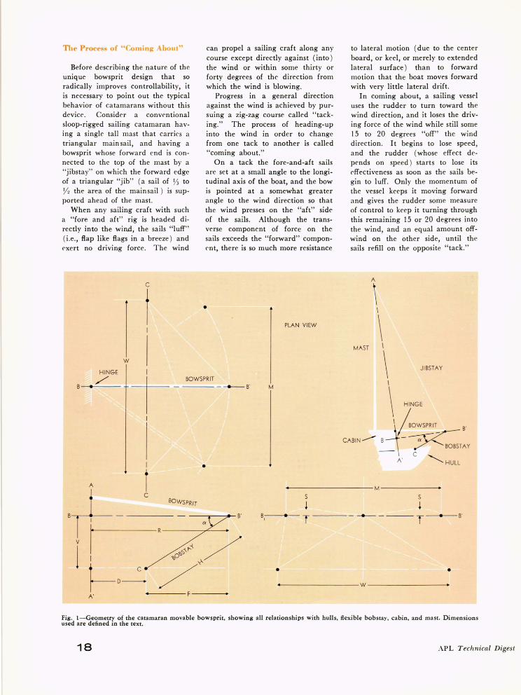
Fig. l-Geometry of the catamaran movable bowsprit, showing all relationships with hulls, flexible bobstay, cabin, and mast. Dimensions used are defined in the text.
18 APL Technical Digest
A catamaran suffers a two-fold disadvantage during this period: being so much lighter than a keel boat, it slows down far more rapidly; and having two long hulls instead of one, it resists turning more and takes longer to complete the turn necessary to put it on a new tack. For these reasons catamarans often fail in their efforts to come about, especially if there are waves of any size tending to resist heading up into the wind.
In the absence of auxiliary power, it then becomes necessary to "wear around," which means to turn away from the wind and make an almost complete circle around onto the new tack. This involves the process of "jibing"-a sudden shifting of wind pressure from one side of the sails to the other when the wind is directly behind. This is not a desirable maneuver when the wind is very strong.
Achieving Complete Control by Wind Alone
Three separate problems had to be solved before a rigging could be designed to overcome these disadvantages. First was the aerodynamic and hydrodynamic problem of determining how sails can be used to provide positive and adequate control, by wind power alone, when rudder control becomes weak or nonexistent through loss of forward velocity. Second was the mechanical problem of designing a structurally sound and functionally satisfactory mechanism for placing sails where they could exercise the degree of control required for this purpose. Third was the mathematical problem of determining dimensional relationships for this mechanism which would permit moving sails as required without changing the distance between bowsprit head and mast head enough to impair the tautness of the jibstay.
These are not trivial problems. Long and arduous work has gone into the set of coordinated solutions which were incorporated in a new catamaran launched in August 1964. The extraordinary performance of this vessel has prompted the author to share the secrets of this design wi th others.
Mm'ch -April 1965
Using the Jib to Turn the Catanlaran
When all sails are 1 uffing, the forward motion of the craft diminishes rapidly, and with it, the power of the rudder to maintain the turning motion toward the wind, a motion which is opposed by both wind and wave. At this point skippers sometimes "back" the jib by pulling its aft end to the leeward side so that the wind presses against the forward side of the sail.
This produces a backward thrust that causes the forward speed to fall even more rapidly, but it also has a turning effect that assists the rudders in making the bows turn into the wind. If this increased turning rate more than offsets the more rapid loss of forward speed, the "backed" jib does some good; too often, however, the net benefit is small and is often insufficient to overcome the adverse effects of wind and wave.
The reason for this is obvious . The line of thrust generated by this backed sail, whose center of pres-
sure is still on the leeward side of the boat's centerline, is directed more backward than sidewise, and crosses the centerline a very short distance ahead of the center of underwater resistance about which the boat turns. Because of this short lever arm, the pressure on the sail is relatively ineffective when the forward edge of the jib is in the center.
The remedy is, of course, to move the jib to a point where it will have a much larger lever arm and greater turning capability. To accomplish this we move the head of the bowsprit from the center line of the boat to a point near or over the center line of the windward hull, thus placing the center-of-pressure of the backed jib on the windward instead of the leeward side of the boat's center line, while it is still trying to "head up." This, together with the direction of the line of thrust, which gets farther and farther away from the boat's center line as the boat turns, gives the jib four or five times as much lever arm as it has when centered, and pro-
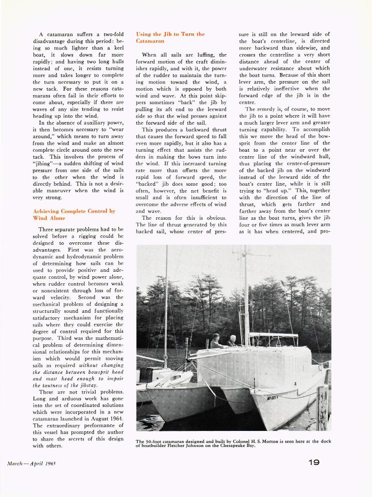
The 30-foot catamaran designed and built by Colonel H. S. Morton is seen here at the dock of boatbuilder Fletcher Johnson on the Chesapeake Bay.
19

duces a turning force as great or greater than tha t produced by the' rudders.
As the turn continues, this lever arm tends to i'ncrease, with the result that the turning effort genera ted by the backed jib, with its forward end over the wind\yard bow, increases at the same time rudder action decreases. The observed result is a rapid rate of turning, which does not appear to diminish appreciably, even when forward motion diminishes or even ceases.
The aerodynamic - hydrodynamic problem can, therefore, be solved by moving the head of the bowspri t over to the side if this can be done without detrimental change in jibstay tension.
The Mechanical Desi~n Problem
A fixed bowsprit can be mounted on a typical catamaran with an elegantly simple rigging of great strength. The bowsprit, which is a solid member under compression, has its aft end attached to the center of the transverse superstructure of the catamaran, at a point substantially above the level of the forward decks of the two hulls.
The forward end of the bowsprit is connected with the upper end of the mast by the jibstay, a heavy wire on which the jib is mounted . Two "bobstays" from the bowsprit, one to each catamaran hull (Fig. 1) , hold the front end down and oppose the jibstay tension. The lateral spacing between hulls also enables the bobstays to restrain the bowsprit head against lateral motion . The whole forms a structurally adequa te assembly of utmost simplicity.
It is fortunate, indeed, that two very simple modifications of this conventional design can convert it into a " movable bowsprit" system tha t is capable of providing the required displacement of the bowsprit head without sacrificing the basic simplicity of its structural elements.
1. The solid attachment of the aft end of the bowsprit to the superstructure is replaced by a hinge or pivot that allows the bowsprit head to turn about the axis A-A' (Fig. 1 ), with some leeway for vertical motion out of the plane B-B'.
2. The two separate bobstays attached to the front end of the usual bowsprit are replaced by a single continuous bobstay that is made of
Colonel Morton is at the helm of his craft. In the background are Digest staff member J . W. Howe, Jr. (left) and layout artist W . C. Lucinski.
20
fl exible halyard wire so that it can run over a sheave attached to the forward end of the bowsprit.
With proper dimensional relationships (discussed in the next section ) the head of the bowsprit can now be swung from side to side over the entire range of positions from one bow to the other, maintammg proper tension on all wires in all pOSItIOns. The lateral position of the bowsprit head is now controlled by the skipper through "sheets," ropes that are similar to those that control the position of the sails.
With proper dimensional relationships between the elements of this mechanica l design, the bowsprit head ca n be moved far enough to either side to enable the backed jib to keep the bows turning, and the process of coming about can be completed promptly and positively. But the determination of " proper dimensional relations" is a mathematical problem of challenging complexity.
Mathematics of the MovablE' Bowsprit
Attention is invited to Fig. 1, which shows (upper right ) a side eleva tion of the bowsprit in its center position, with the jibstay attached to its front end a nd with its aft end hinged to the cabin structure. T he single bobstay passes over a sheave attached to the bowsprit head , a nd its ends are made fast to the two widely separa ted bows of the hulls.
With a jibstay of fixed length connecting the top of the mast to the bowsprit, the head of the bowsprit descr ibes an arc of a circle about the axis of rota tion, A-A', in the plane, B-B', perpendicular to this axis. At the same time the sheave on the bowsprit head, moving along the bobstay wire, describes an arc of an ellipse in the plane of the two b ranches of the wire. T his plane keeps rota ting about the line joining the fixed ends of the bobstay and becomes more nearly vertical as the bowsprit head moves away from center.
M athem atical ana lysis shows tha t this arc of the ellipse (generated by keeping the bobstay taut ) will not keep the head of the bowsprit exactly
.\PL T echnical D igest

in plane B-B' during lateral motion of the head. If it is in plane B-B' when the bowsprit is centered (see lower right of Fig. 1) it can be in the plane at two points of maximum lateral displacement; however, at all intermediate points it will lie above plane B-B'.
This means that the bob stay does not hold the jibstay length absolutely constant during lateral motion ; on the contrary it relaxes tension during lateral motion and only returns to the original center-position tension at full "allowable" lateral displacement. The jibstay will not allow motion beyond this point on either side.
A half dozen equations that define all essential dimensional relationships will be given, but their derivation is too lengthy for inclusion in this paper. These equations and a few graphs and tabulated values arc all that are required to select compatible sets of dimensions for any installation.
Nine dimensions and an angle will he defin ed before giving the equations which r<'late them (sec Fig. 1) :
W = lateral distance between the fixed ends of the bobstay secured to the two bows of the catamaran hulls. It is at least equal to the distance between center-lines of the two hulls, and may be made greater if anchor points are nea r the outer edges of the hulls.
R = radius of the arc described by the bowsprit head about axis A-A'. This is not exactly the bowsprit length unless the hinge lies in the plane B-B'; in general it does not.
D = the distance from axis A-A' to line C-C', joining the bobsta y fixed end poin ts .
F = R-D L = total length of the bobstay.
(This is the only dimension not shown in true length on Fig. 1. )
H = dista nce from line C-C' to the head of the bowsprit when it is in its center position.
V = height of plane B-B' above line C-C'.
Mm'ch -April 1965
38 0 r-------~------~------.-------~------_.------~------~------~
34° ~------+-------+-------~~----~-------r------_+------_+------~
32° r-------+-~~--+-------1-------~------~~----_+------_+------~
30° ~------+-------+-----~~------~------~-------+-------+--~~~
280 ~--~~+-------+-------4-------~--~~~-------+-------+------~
24° ~ ______ ~ ______ ~ ______ ~~~ __ ~ ______ ~ ______ ~ ______ ~ ______ ~
0.34 0.36 0.38 0.40 0.42
D/ R
0.44 0.46 0.48 0.50
Fig. 2-Elfects on the value of angle a of the ratio of D (distance between the bowsprit hinge and the axis of the fixed ends of the bob stay ) to R (radius of the bowsprit arc) for three given ratios of R to W (lateral distance between the fixed ends of the bobstay).
{\' = angle between plane B-B' and plane of the bobstay wires when the bowsprit is centered.
These seven dimensions and the angle a would apply to the bowsprit if it were permanently fixed in its center position. Only the two other dimensions mentioned below have to do with the lateral motion of the bowsprit head ; but they are the two whose proper and acceptable values d epend on correct relationships between the other dimensions.
M = maximum lateral motion of the bowsprit head. The bowsprit head lies in plane B-B' in its center position, and again when it is a distance M/2 either side of center.
S = the maximum distance above plane B-B' which the bobstay allows the bowsprit head to rise, and is an approximate measure of the slackening of the jibstay.
Since the purpose of the movable bowsprit is to give a back~d jib a large increase in effective lever arm,
there is every reason to make M as large as possible without adversely affecting other factors. It should not he made less than about 80 % of W and can be 90 o/r- or even 100% of W, with certain limitations on other dimensions.
In general, the dimension S, which measures a change in jibstay tension, should not be allowed to become too large, but it is by no means necessary for it to approach zero. There is always some slack in a jibstay so that it can deflect laterally a small fraction of its length, in order that its tension will not be excessively high .
It is not difficult to select dimensional relationships that will keep S well within the normal range of tension adjustments that are permissible for a jibstay wire.
The general solution for this problem relates all dimensions to one another In the form of ratios, particularly the ratios of various other dimensions to width W. This is the basic dimension to which all other dimensions of any specific drsign are related :
21

1 +
( I )
(~r - 1
Gfr ( 2 ) 4
(tvr (~r(I -%r (3)
(rvr = (~r - (tv):
and
(tv ) cos a = (It) ,
(4 )
(5 )
It will save the reader who proposes to use these equations a lot of time if some indication is given of the practical range of values for these ratios.
It is suggested that calculations be started for M / W = 1.00 since turnbuckle adjustments of the bobstay length L are sufficient to change this to lower values if necessary. It may be pointed out that reducing M/W by turnbuckle adjustment ( lengthening L ) decreases S / W four or five times as rapidly as it does M / W. The only reason one would need to make M / W much less than 1.00 ,,<ould be to reduce S / W to a more
acceptable value. The optimum value for R / W is
approximately 0.80, but values anywhere from 0.75 to 0.85 are permissible if the values of the angle a
which they produce are satisfactory. The ratio D / R should lie in the
range from YJ to Yi , with smaller values being better in several respects. Figure 2 shows the effects of both R/ Wand D / R on the value of a. Figure 3 illustrates the same data in graphical form.
By reference to these figures one can select values for both R / W and D/ R compatible with an angk a suitable for a ny specific design. The Table following gives L / W values computed by Eq. ( 1 ) for M/W = 1.00 over the useful range of R / W and D/ R values. These are kngths with the turnbuckles com-
22
R/ W = 0.75 R/ W = 0.80 R/ W = 0.85
O/ R O/ R O/ R 0.50 0.50 0.50 0.42 0.42 0.42 0.34 0.34 0.34
I I I I
--t --+ --+ Fig. 3-Elfects of angle a on the ratios of R to Wand of D to R.
L / W VALUES FOR BOB STAY LENGTHS WITH TURNBUCKLES AT
MINIMUM ELONGATION (M/W = 1.00 )
D R
0.34 0.36 0.38 0040 0042 0.44 0046 0.48 0.50
Percent in- ( nease in L which reduces M / W from 1.00 to 0.90
R 0.75
W
L W
1.602 1.557 1.5ICi 1.47fl 1.442 1.408 1.377 1.3-!8 1.321
1.6
R 0.80
R 0.85
W W
values which make M
1.00 W
1.618 1.629 1.573 1.584 1.53 1 1.542 1.492 1.503 1.456 1.467 1.422 1.433
1.391 1.402 1.362 1.373 1.335 1.346
1.3 1.1
Lengthening the bobstay hy extending the turnhuckles deneases hoth W/ W and S/ W.
o ~ ____ ~ ______ ~ ______ ~ ______ ~ ____ ~~ ____ ~ ______ ~ ____ ~ 0.34 0.36 0.38 0.40 0.42 0.44 0.46 0.48 0.50
O/ R
Fig. 4-Elfects on the ratio S (maximum rise of the bowsprit above plane B-B') to W of D/R for given values of the ratio M (maximum lateral motion of the bowsprit head) to W.
.-\P L Technical Digest
pletely closed, so that any turnbuckle adjustments will lengthen L and decrease M I W and S I W.
Table I shows that the adjustment necessary to reduce M I W from 1.00 to 0.90 (with far larger decreases in SI W ) is well within the capability of normal turnbuckle adjustment. One other possible adjustment can be made which has a similar effect: if the two hold-down fittings by which the bobstay ends are anchored to the hulls have two or more holes separated by a percent or two of the dimension D, the effects of increasing D are qualitatively similar to lengthening L but are of the
HONORS
C. B. Swartz and A. Michelsen have been named by the President of The Johns Hopkins University as 1965-66 recipients of William S. Parsons Fellowships. Both men will begin an academic year of work at the University in the fall of 1965.
Dr. Swartz, who is Supervisor of the Logical Programming Project in the Computing Center, will develop and teach a course in computer science, being concerned with the subject from the point of view of the working scientist.
Mr. Michelsen will be associated with the School of Hygiene and Public Health and will investigate biological effects of x-radiation relative to protection, therapy, and general health physics. He is a member of the staff of the Equipment Research and Development P.roject in the Fleet Systems Division.
order of half as great as those prod uced by changing L.
Either or both of these adjustmepts produce changes in V and /l',
as well as in M and S. Figure 4 gives the final informa
tion needed to show whether M I W needs to be reduced by lengthening L in order to bring S I W down to lower values. It shows why, as was previously stated, the smaller D I R val ues are better. If D I R is large it may be desirable to reduce MIW by a few percent to secure much larger reductions in SI W.
The fraction of jibstay length by which the bowsprit head rises above
plane B-B' is much smaller than SI W, since a typical jibstay is likely to be some three and a half times W.
This paper will not undertake to set a maximum permissible SIW value, since most yachtsmen who may want to use the foregoing graphs and formulas will have a good idea of what is acceptable. It may be said, however, that if Fig. 4 is used to select combinations of DI R and MIW that avoid the high S I W values on the upper right, no combination of dimensions on this graph will permit any seriously objectiomible change in jibstay tension.
PUBLICATIONS The following list is a compilation of recently published books and
technical articles written by APL staff members.
L. W. Ehrlich, "The Block Symmetric Successive Overrelaxation Method," ]. Soc. Indust. Appl. Math ., 12, Dec. 1964, 807-826.
R. G. Munn, F. J. Smith, and E. A. Mason (University of Maryland ) and L. Monchick (APL), "Transport Collision Integrals for Quantum Gases Obeying a 12-6 Potential," J. Chem. Phys., 42, Jan. 15, 1965, 537-539.
W. G. Berl, "Instability in Solid Rockets," Astronautics and Aeronautics, 3, Feb. 1965, 54-62.
S. D. Bruck and R. R . Rector, "New Drip- and Leak-Proof Precision Syringe," Rev. Sci. Instruments, 36, Feb. 1965, 239-240.
W. E . Buchanan, "Navy's Transit Satellites Showing the Way in Outer Space," Navy-The Magazine of Sea Power, 8, Feb. 1965, 7-10.
R. M. Fristrom, "Definition of
Burning Velocity and a Geometric Interpretation of the Effects of Flame Curvature," Phys. Fluids .. 8, Feb. 1965, 273-280.
W. Liben, "Monkeys and Microelectronics," Electronics, 38, Feb. 1965, 90-93.
]. T. Massey and S. M. Cannon, "Constricted Discharges in the Rare Gases. I. Spectroscopic and Electrical Measurements," ]. Appl. Phys., 36, Feb. 1965, 361-372.
J. T. Massey, "Constricted Discharges in the Rare Gases. II. Analysis of the Macroscopic Properties of the Discharge," ]. Appl. Phys. , 36, Feb. 1965, 373-380.
J. T. Massey, A. G. Schulz, B. F . Hochheimer, and S. M. Cannon, "Resonant Energy Transfer Studies in a Helium-Neon Gas Discharge," J Appl. Phys ., 36, Feb. 1965, 658-659.
-BOOKS
APL COLLOQUIA V. Uzunoglu, Semiconductor Network Analysis and Design, McGraw-Hill Book Co., Inc., New York, 1964.
Apr. 2-"Stability of Automobiles," by D. L. Nordeen, General Motors Research Laboratory.
Apr. 9-"An Interpretation of Martian Phenomena," by C. C. Kiess, Georgetown University.
May 7- "Optical Holography and X-Ray Microscopy," by G. W. Stroke, University of Michigan.
MaTch -APTil 1965
May 14-"Progress In Quantum Electronics," by B. Lax, Lincoln Laboratory. May 21-"Computer Systems 1967," by C. H. We isert, Applied Physics Laboratory. May 28- "Reccnt Progress in Field Emission and Its Applications," by W. P. Dyke, Field Emission Corporation .
S. D. Bruck, "Thermogravimetric Studies on an Aromatic Polyimide in Air and in the Vacuum Region of 10-2 to 10-3 Torr Using the Cahn RG Electrobalance," V acuum Microbalance Techniques 4, Plenum Press, New York, 1965, 247-278.
23