
Uniform Technical Prescription · UTP LOC&PAS Page 2 of 266 Status: DRAFT Version: 01 Ref.:...
266
Uniform Technical Prescription Applicable to the Rolling Stock subsystem: LOCOMOTIVES AND PASSENGER ROLLING STOCK UTP LOC&PAS 2015 Applicable from
Transcript of Uniform Technical Prescription · UTP LOC&PAS Page 2 of 266 Status: DRAFT Version: 01 Ref.:...
Uniform Technical Prescription
Applicable to the Rolling Stock subsystem:
LOCOMOTIVES AND PASSENGER ROLLING STOCK
UTP LOC&PAS 2015
Applicable from
OTIF ROLLING STOCK
LOCOMOTIVES AND PASSENGER ROLLING STOCK
UTP LOC&PAS Page 2 of 266
Status: DRAFT Version: 01 Ref.: TECH-20023 Original: EN Date:19.5.2020
Amendments record
Reference Date Description and comments
Version 1 19.05.2020 First draft for review by WG TECH 40.
Changes are indicated in track changes compared to the version of
UTP LOC&PAS which entered into force on 1 January 2015.
The following EU documents have been used as input:
- Regulation (EU) 2016/919 of 27 May 2016 (CCS TSI)
- Regulation (EU) 2018/868 of 13 June 2018 (on Energy
Measuring system and data collecting system)
- Regulation (EU) 2019/776 of 16 May 2019
(Amendments to TSIs)
- Regulation (EU) 2020/387 of 9 March 2020 (Extension
of the Area of Use)
Main amendments:
Alignment with Commission Implementing Regulation
(EU) 2019/776 of 16 may 2019 (4th Railway Package).
Alignment with energy measuring system and data
collection system requirements
Modifications to better reflect responsibilities of the
Secretary General, the CTE and Member States.
Deletion of Appendix K as parameters are to be covered
in a new UTP on train composition and route
compatibility checks (UTP TCRC)

OTIF ROLLING STOCK
LOCOMOTIVES AND PASSENGER ROLLING STOCK
UTP LOC&PAS Page 3 of 266
Status: DRAFT Version: 01 Ref.: TECH-20023 Original: EN Date:19.5.2020
APTU Uniform Rules (Appendix F to COTIF 1999)
Uniform Technical Prescriptions (UTP) applicable to
the Rolling Stock subsystem:
LOCOMOTIVES AND PASSENGER ROLLING STOCK - (UTP
LOC&PAS)
This UTP has been developed in accordance with Article 8 of APTU (Appendix F to COTIF), in the
version as last amended by the OTIF Revision Committee 2018, which entered into force on 1 March
2019. For definitions see also Article 2 of APTU and Article 2 of ATMF (Appendix G to COTIF).These
regulations have been developed in accordance with the provisions of APTU, in particular
Article 8, in the version as amended by the OTIF Revision Committee in 2009, which entered
into force on 1 December 2010. For definitions and terms, see also Article 2 of APTU (Appendix
F) and Article 2 of ATMF (Appendix G), both Appendices to the 1999 version of the COTIF
Convention as applicable since 1 December 2010. Footnotes (which are not part of the
regulationslegal provisions), they include both explanatory information and references to other
regulations.
Explanatory note:
The texts of this UTP which appear across two columns are identical to corresponding texts of
the European Union regulations. Texts which appear in two columns differ; the left-hand
column contains the UTP regulations, the right-hand column shows the text in the corresponding
EU regulations. The text in the right-hand column is for information only and is not part of the
OTIF regulations. Texts in the right-hand column which are not quoted from the LOC&PAS
TSI, but from other EU regulations, are in italics.
0. PURPOSE AND EQUIVALENCE AND TRANSITIONAL PROVISIONS
Following their adoption by the Committee of
Technical Experts, the OTIF regulations provisions
included in this document are declared equivalent to
the corresponding EU regulations within the
meaning of Article 13 § 4 of APTU1 and Article 3a
of ATMF2, in particular with:
1 APTU means the Uniform Rules concerning the Validation of Technical Standards and the Adoption of Uniform Technical Prescriptions applicable to Railway Material intended to be used in International Traffic – Appendix F to COTIF 1999 in the revised version that entered into force on 1 December March 20190.
2 ATMF means the Uniform Rules concerning Technical Admission of Railway Material used in International Traffic – Appendix G to COTIF 1999 in the revised version that entered into force on 1 December March 20190.
OTIF ROLLING STOCK
LOCOMOTIVES AND PASSENGER ROLLING STOCK
UTP LOC&PAS Page 4 of 266
Status: DRAFT Version: 01 Ref.: TECH-20023 Original: EN Date:19.5.2020
Commission Regulation (EU) No
1302/2014 of 18 November 2014
concerning a technical specification for
interoperability relating to the ‘rolling
stock — locomotives and passenger
rolling stock’ subsystem of the rail
system in the European Union The TSI
for Locomotives and Passenger Rolling
Stock Commission Regulation as last
amended by Commission Implementing
Regulation (EU) 2019/776 of 16 May
2019, hereinafter referred to as LOC&PAS
TSI: 2014.
Commission Implementing Regulation
(EU) 2018/868 of 13 June 2018
amending Regulation (EU) No
1301/2014 and Regulation (EU) No
1302/2014 as regards provisions on
energy measuring system and data
collecting system.
In addition, this UTP contains the
following Appendix:
Appendix K, setting out the
provisions for the safe operation of
rolling stock. Equivalent provisions in
the EU are part of the OPE TSI
(Commission Decision 2012/757/EU
of 14 November 2012).
Transitional provisions for the application of this
UTP are laid down in chapter 7.
Reference to articles in the EU Decision enacting
the LOC&PAS TSI:
This UTP enters into force on 1.1.2015. Without
prejudice to section 7, from the date of entry into
force this UTP shall apply to all new rolling stock
admitted to international traffic as defined in
ATMF.
Article 3
1. Without prejudice to Articles 8 and 9, and point
7.1.1 of the Annex, the TSI shall apply to all new
rolling stock of the rail system in the Union,
defined in Article 2(1), which is placed in service
from 1.1.2015.
From the date of entry into force this UTP shall
apply to rolling stock that is renewed or upgraded in
accordance with the provisions in section 7.1.2.
2. The TSI shall not apply to existing rolling stock
of the rail system in the European Union which is
already placed in service on all or part of the
network of any Member State on 1 January.1.
2015, except when it is subject to renewal or
upgrading in accordance with Article 20 of
Directive 2008/57/EC and Section 7.1.2 of the
Annex.
OTIF ROLLING STOCK
LOCOMOTIVES AND PASSENGER ROLLING STOCK
UTP LOC&PAS Page 5 of 266
Status: DRAFT Version: 01 Ref.: TECH-20023 Original: EN Date:19.5.2020
This UTP contains open points as listed in Appendix
I. With respect to these open points, Contracting
States should notify their applicable National
Technical Requirements in accordance with APTU
Article 12 § 2.
Article 4
1. With regard to the aspects classified listed as
'open points' set out in Appendix I of the Annex to
this Regulation, the conditions to be complied
with for verifying the essential requirements set
out in Annex III to interoperability pursuant to
Article 17(2) of Directive (EU) 201608/79757/EC
shall be those laid down by national rules
applicable in force in the Member States which
are part of the area of use of the vehicles
authorises the placing in service of the
subsystemcovered by this Regulation.
Vehicles which are subject to either:
open points as defined in this UTP, or
specific cases as defined in this UTP or in
the LOC&PAS TSI, which limit the
conditions of admission, or
are subject to a derogation in accordance
with ATMF Annex B,
are subject to admission in accordance with ATMF
Article 6 § 4.
For Elements of Construction (ICs) which are
assessed separately from the subsystem in
accordance with section 5.1 of this UTP: after a
transitional period ending on 31 May 2017 all newly
produced ICs shall be covered by the required
declaration of conformity and/or suitability for use.
Until 31 May 2017, the provisions of section 6.3 of
this UTP apply.
Rolling stock admitted to international operation
after 31 May 2017 shall not include non-certified
and separately assessed ICs.
Transitional periods prescribed in points: 4.2.3.1,
6.3.1, 7.1.1. are valid as follows…
Article 8
1. An 'EC' certificate of verification for a
subsystem that contains interoperability
constituents which do not have an 'EC'
declaration of conformity or suitability for use
may be issued during a transitional period ending
on 31 May 2017 provided the provisions laid
down in Section 6.3 of the Annex are met.
2. The production or upgrade/renewal of the
subsystem using non-certified interoperability
constituents shall be completed within the
transitional period set out in paragraph 1,
including the placing in service.
The objectives and scope of COTIF and the EU law
concerning railways are not identical and it has
therefore been necessary to use different
terminology for concepts that have a similar but not
identical meaning. The following table lists the
terms used in this UTP and the corresponding terms
used in the relevant TSI:
This UTP EU law

OTIF ROLLING STOCK
LOCOMOTIVES AND PASSENGER ROLLING STOCK
UTP LOC&PAS Page 6 of 266
Status: DRAFT Version: 01 Ref.: TECH-20023 Original: EN Date:19.5.2020
Uniform Technical
Prescriptions (UTP)
Technical
Specification of
Interoperability (TSI)
UTP PRM PRM TSI
UTP NOI NOI TSI
UTP GEN-G CSM on RA
UTP LOC&PAS LOC&PAS TSI
UTP INF INF TSI
UTP GEN-G CSM on RA
Competent Authority
National Safety
Authority or
authorising entity
UTP verification
procedure
EC verification
procedure
Assessing entity Notified body
Type or design
examination
certificate
EC type or design
examination
certificate
UTP declaration for
verification
EC declaration for
verification
Assessment
procedures for the
verification of
subsystems (modules)
EC verification of a
subsystem (modules)
Assessment
procedures for the
verification of
elements of
construction
Modules for EC
certification of
conformity of
interoperability
constituents
UTP certificate of
verification
Certificate of “EC”
verification
Contracting State Member State
Where provisions in this UTP and the LOC&PAS
TSI differ in substance, the respective texts are in a
OTIF ROLLING STOCK
LOCOMOTIVES AND PASSENGER ROLLING STOCK
UTP LOC&PAS Page 7 of 266
Status: DRAFT Version: 01 Ref.: TECH-20023 Original: EN Date:19.5.2020
2-column format. The left-hand column and the full
width texts show the UTP provisions (OTIF
regulations) and the right-hand column shows the
European Union TSI texts. Texts in the right-hand
column are strictly for information only. For EU
law, consult the Official Journal of the European
Union.
Where differences between texts of this UTP and
the European Union LOC&PAS TSI are either
editorial, or not substantive, or concern the list of
terms quoted above, the LOC&PAS TSI texts are
not generally reproduced. The TSI texts may
however be reproduced to improve clarity and
readability.
OTIF ROLLING STOCK
LOCOMOTIVES AND PASSENGER ROLLING STOCK
UTP LOC&PAS Page 8 of 266
Status: DRAFT Version: 01 Ref.: TECH-20023 Original: EN Date:19.5.2020
1. INTRODUCTION
1.1. Technical scope
This
Uniform Technical Prescription (UTP) technical specification for interoperability (TSI)
is a specification by which a particular subsystem is addressed in order to meet the essential requirements
and ensure the interoperability
of the technical systems and components necessary
in international rail traffic transport as described by
Article 3 § 3 of APTU.
of the Union's rail system as described in Article
1 of Directive (EU) 2016/7973 2008/57/EC.
The particular subsystem is the rolling stock
referred to in section 2.7 of UTP GEN-B4 of the Union's rail system referred to in Annex II
section 2.7 of Annex II to Directive (EU)
2016/7972008/57/EC.
This
UTP TSI
is applicable to rolling stock:
which is (or is intended to be) operated
in international traffic on the rail network defined in the section 1.2
“Geographical scope” of this TSI
And
which is of one of the following types
(as defined in section 2.7 of UTP GEN-B): (as defined in Annex I sections 1.2 and 2.2 of
Annex I to Directive (EU)
2016/7972008/57/EC):
Self-propelling thermal or electric trains;
Thermal or electric traction units;
Passenger carriages;
Mobile railway infrastructure construction and maintenance equipment.
3 Directive (EU) 2016/797 of the European Parliament and of the Council of 11 May 2016 on the interoperability of the rail system within the European Union (OJ L 138, 26.5.2016, p. 44). Directive 2008/57/EC of the European Parliament and of the Council of 17 June 2008 on the interoperability of the rail system within the Community (OJ L 191, 18.07.2008, p.1.)
4 Subsystems– General Provisions, UTP GEN-B 2017 as last amended on 1 June 2019, APTU (A 94-01B/1.2012)
OTIF ROLLING STOCK
LOCOMOTIVES AND PASSENGER ROLLING STOCK
UTP LOC&PAS Page 9 of 266
Status: DRAFT Version: 01 Ref.: TECH-20023 Original: EN Date:19.5.2020
Rolling stock of the types mentioned in Article
1 (3) and (4) of Directive (EU)
2016/7972008/57/EC are excluded from the
scope of this TSI:
Metros, tram, and other light rail vehicles;
Vehicles for the operation of local, urban or
suburban passenger services on networks that
are functionally separate from the rest of the
railway system;
Vehicles exclusively used on privately owned
railway infrastructure that exist solely for use by
the owner for its own freight operations;
Vehicles reserved for a strictly local, historical or
touristic use.
The detailed definition of the rolling stock in the scope of this
UTP TSI
is given in Chapter 2.
(a) On the basis of Article 6 of ATMF, for the part of
the vehicle which is compliant with this UTP or
part of it, competent authorities of Contracting
States have to accept verifications that have been
made by other competent authorities or assessing
entities according to this UTP.
Additional verifications of the rolling stock
subsystem of vehicles that fully comply with this
UTP by competent authorities of Contracting States
shall be limited to:
Specific cases identified in chapter 7 which
affect technical compatibility with the
network of the Contracting State
concerned,
Technical compatibility with the network
of the Contracting State concerned,
Provisions related to the open point
identified in this UTP and the National
Technical Requirements notified in
accordance with Article 12 of APTU.
1.2. Geographical scope
The geographical scope of this

OTIF ROLLING STOCK
LOCOMOTIVES AND PASSENGER ROLLING STOCK
UTP LOC&PAS Page 10 of 266
Status: DRAFT Version: 01 Ref.: TECH-20023 Original: EN Date:19.5.2020
UTP comprises all lines open to, or used for
international traffic, taking into account the
limitation as set out in Section 1.1.
TSI is the Union rail system as set out in Annex
I to Directive (EU) 2016/797 and excludes the
cases referred to in Articles 1 (3) and (4) of
Directive (EU) 2016/797.network of the whole
rail system, composed of:
The trans-European conventional rail system
network (TEN) as described in Annex I section
1.1 “Network” of Directive 2008/57/EC
The trans-European high-speed rail system
network (TEN) as described in Annex I section
2.1 “Network” of Directive 2008/57/EC
Other parts of the network of the whole rail
system, following the extension of the scope as
described in Annex I section 4 of Directive
2008/57/EC,
and excludes the cases referred to in Article 1(3)
of Directive 2008/57/EC.
1.3. Content of this UTP
In accordance with Article 8 § 4 of APTU this UTP: In accordance with Article 54(3) of Directive
(EU) 2016/797 2008/57/EC this TSI:
(a) indicates its intended scope (Chapter 2);
(b) lays down essential requirements for the subsystem rolling stock “'Locomotives and passenger rolling
stock”' and its interfaces vis-à-vis other subsystems (Chapter 3);
(c) establishes the functional and technical specifications to be met by the subsystem and its interfaces vis-
à-vis other subsystems (Chapter 4);
(d) determines the
elements of construction (also referred to in this
document as interoperability constituents or ICs)
interoperability constituents
and interfaces which must be covered by
technical standards European specifications, including European
standards,
which are necessary to achieve interoperability within the
European Union's
rail system (Chapter 5);
(e) states, in each case under consideration, which procedures are to be used in order to assess the conformity
OTIF ROLLING STOCK
LOCOMOTIVES AND PASSENGER ROLLING STOCK
UTP LOC&PAS Page 11 of 266
Status: DRAFT Version: 01 Ref.: TECH-20023 Original: EN Date:19.5.2020
with the provisions of the UTP. These procedures
are based on the assessment modules defined in
UTP GEN-D5
or the suitability for use of the interoperability
constituents, on the one hand, or the “EC”
verification of the subsystems, on the other hand
(Chapter 6);
(f) indicates the strategy for implementing this
UTP TSI
(Chapter 7);
(g) indicates for the staff concerned, the professional qualifications and health and safety conditions at work
required for the operation and maintenance of the subsystem, as well as for the implementation of this
UTP TSI
(Chapter 4).
(h) indicates the provisions applicable to the existing “rolling stock” subsystem, in particular in the event of
upgrading and renewal and, in such cases, the modification work which requires an application for a new
Admission to operation in international traffics
(Chapter 7);
authorisation;
(i) indicates the parameters of “rolling stock” subsystem to be checked by the railway undertaking and the
procedures to be applied to check those parameters
to ensure compatibility between vehicles and the
routes on which they are operated .
after the delivery of the vehicle authorisation for
placing on the market and before the first use of
the vehicle to ensure compatibility between
vehicles and the routes on which they are to be
operated.
In accordance with
Article 8 § 46 of APTU, Article 54(5) of Directive (EU)
2016/7972008/57/EC,
provisions may be made for specific cases for each
UTP; TSI;
such for specific cases are indicated in Chapter 7.
5 Assessment procedures (modules)– General Provisions, UTP, APTU (A 94-01D/3.2011)
OTIF ROLLING STOCK
LOCOMOTIVES AND PASSENGER ROLLING STOCK
UTP LOC&PAS Page 12 of 266
Status: DRAFT Version: 01 Ref.: TECH-20023 Original: EN Date:19.5.2020
2. ROLLING STOCK SUBSYSTEM AND FUNCTIONS
2.1. The rolling stock subsystem as part of the
rail system
The rolling stock subsystem as part of the
Union's rail system
The rail system The Union's rail system
has been broken down into the following subsystems, as defined in
Chapter 1 of UTP GEN-B: Annex II (section 1) of Directive (EU)
2016/7972008/57/EC:
(1)(2) Structural areas:
infrastructure;
energy;
trackside control-command and signalling;
on-board control-command and signalling;
rolling stock;
(2)(3) Functional areas:
operation and traffic management;
maintenance;
telematics applications for passenger and freight services.
With the exception of maintenance, each sub-system is dealt with in specific
UTP(s). TSI(s).
The rolling stock subsystem dealt with in this
UTP TSI
(as defined in Section 1.1) has interfaces with all other subsystems of the
Union
rail system mentioned above; these interfaces are considered within the frame of an integrated system,
compliant with all the relevant
UTPs. TSIs.
Additionally, there are two
TSIs describing
specific aspects of the railway system and concerning several subsystems, the rolling stock subsystem
being one of them:

OTIF ROLLING STOCK
LOCOMOTIVES AND PASSENGER ROLLING STOCK
UTP LOC&PAS Page 13 of 266
Status: DRAFT Version: 01 Ref.: TECH-20023 Original: EN Date:19.5.2020
(1) safety in railway tunnels
The vehicle related requirements for the safe
operation of trains in tunnels are included in this
UTP. Specific requirements for the infrastructure
and operations related to tunnels are presumed to be
defined in each Contracting State in such a way that
vehicles compliant with this UTP may be operated
in tunnels.
(SRT TSI);
(2) accessibility for people with reduced mobility
(UTP PRM) (PRM TSI).
and two
UTPs TSIs
concerning particular aspects of the rolling stock subsystem:
(3) noise
(UTP NOI); (TSI Noise);
(4) freight wagons.
The requirements concerning the rolling stock subsystem expressed in
the UTP NOI, UTP WAG and the UTP PRM these four TSIs
are not repeated in the present
UTP. TSI.
The UTP NOI, UTP WAG and the UTP PRM These four TSIs
apply also for the rolling stock subsystem according to their respective scopes and implementation rules.
2.2. Definitions related to rolling stock
For the purpose of this
UTP, TSI,
the following definitions apply:
2.2.1. Train formation:
(1) A Unit is the generic term used to name the rolling stock which is subject to the application of this
UTP TSI
OTIF ROLLING STOCK
LOCOMOTIVES AND PASSENGER ROLLING STOCK
UTP LOC&PAS Page 14 of 266
Status: DRAFT Version: 01 Ref.: TECH-20023 Original: EN Date:19.5.2020
and therefore subject to
OTIF technical admission. “EC” verification.
(2) A Unit may be composed of several Vehicles as defined in
Article 2 w) of ATMF; Directive 2008/57/EC, point (3) of Article 2 (c)of
Directive (EU) 2016/797;
considering the scope of this
UTP, TSI,
the use of the term “vehicle” in this
UTP TSI
is limited to the rolling stock subsystem as defined in Chapter 1.
(3) A Train is an operational formation consisting of one or more units.
(4) A Passenger train is an operational formation accessible to passengers (a train composed of Passenger
vehicles but not accessible to passengers is not considered as a Passenger train).
(5) A “Fixed formation” is a train formation that can only be reconfigured within a workshop environment.
(6) A “Predefined formation(s)” is a train formation(s) of several units coupled together, which is defined
at design stage and can be reconfigured during operation.
(7) “Multiple operation” is an operational formation consisting of more than one unit:
Trainsets designed so that several of them (of the type under assessment) are capable of being
coupled together to operate as a single train controlled from 1 driver’s cab.
Locomotives designed so that several of them (of the type under assessment) are capable of being
included in a single train controlled from 1 driver’s cab.
(8) “General operation”: A unit is designed for general operation when the unit is intended to be coupled
with other unit(s) in a train formation which is not defined at design stage.
2.2.2. Rolling stock:
Definitions below are classified in four three groups asdefined in the
section 2.7 of UTP GEN-B.follows: defined in the section 1.2 of Annex I to Directive
(EU) 2016/7972008/57/EC.
A) Locomotives and passenger rolling stock, including thermal or electric traction units, self-
propelling thermal or electric passenger trains, and passenger coaches:
(1) B) Thermal and/or electric traction units
OTIF ROLLING STOCK
LOCOMOTIVES AND PASSENGER ROLLING STOCK
UTP LOC&PAS Page 15 of 266
Status: DRAFT Version: 01 Ref.: TECH-20023 Original: EN Date:19.5.2020
A Locomotive is a traction vehicle (or combination of several vehicles) that is not intended to carry a
payload and has the ability to be uncoupled in normal operation from a train and to operate
independently.
A Shunter is a traction unit designed for use only on shunting yards, stations and depots.
Traction in a train can also be provided by a powered vehicle with or without driving cab, which is not
intended to be uncoupled during normal operation. Such a vehicle is called a Power Unit (or power car)
in general or a Power Head when located at one end of the trainset and fitted with a driving cab.
(2) A) Self-propelling thermal and/or electric passenger trains can be
A Trainset is a fixed formation that can operate as a train; it is by definition not intended to be
reconfigured, except within a workshop environment. It is composed of only motored or of motored
and non-motored vehicles.
An Electric and/or Diesel Multiple Unit is a trainset in which all vehicles are capable of carrying a
payload (passengers or luggage/mail or freight).
A Railcar is a vehicle that can operate autonomously and is capable of carrying a payload (passengers
or luggage/mail or freight).
A tram – train is a vehicle designed for combined
use on both a light-rail infrastructure and a heavy-
rail infrastructure;
B) Thermal and/or electric traction units:
A Locomotive is a traction vehicle (or combination of several vehicles) that is not intended to carry a
payload and has the ability to be uncoupled in normal operation from a train and to operate
independently.
A Shunter is a traction unit designed for use only on shunting yards, stations and depots.
Traction in a train can also be provided by a powered vehicle with or without driving cab, which is not
intended to be uncoupled during normal operation. Such a vehicle is called a Power Unit (or power
car) in general or a Power Head when located at one end of the trainset and fitted with a driving cab.
(3) C) :Passenger carriages coaches and other related cars
A Coach is a vehicle without traction in a fixed or variable formation capable of carrying passengers
(by extension, requirements specified to apply to coaches in this
UTP TSI
are deemed to apply also to restaurant cars, sleeping cars, couchettes cars, etc.).
A Van is a vehicle without traction capable of carrying payload other than passengers, e.g. luggage or
mail, intended to be integrated into a fixed or variable formation which is intended to transport
passengers.
A Driving Trailer is a vehicle without traction equipped with a driving cab.
A coach may be equipped with a driver's cab; such a coach is then named a Driving Coach.
A van may be fitted with a driver's cab and as such is known as a Driving Van.
A Car carrier is a vehicle without traction capable of carrying passenger motor cars without their
passengers and which is intended to be integrated in a passenger train.
OTIF ROLLING STOCK
LOCOMOTIVES AND PASSENGER ROLLING STOCK
UTP LOC&PAS Page 16 of 266
Status: DRAFT Version: 01 Ref.: TECH-20023 Original: EN Date:19.5.2020
A Fixed Rake of Coaches is a formation of several coaches “semi-permanently” coupled together, or
which can be reconfigured only when it is out of service.
B) Freight wagons, including low-deck vehicles designed for the entire network and vehicles
designed to carry lorries
These vehicles are out of the scope of this UTP.
They are covered by UTP WAG.
These vehicles are out of the scope of this TSI.
They are covered by Regulation (EU) No
321/2013 (the “freight wagons” TSI)
C) D) Special vehicles, such as on-track machinesMobile railway infrastructure construction &
maintenance equipment
On track Machines (OTMs) are vehicles specially designed for construction and maintenance of the
track and infrastructure. OTMs are used in different modes: working mode, transport mode as self-
propelling vehicle, transport mode as a hauled vehicle.
Infrastructure inspection vehicles are utilised to monitor the condition of the infrastructure. They are
operated in the same way as freight or passenger trains, with no distinction between transport and
working modes.
2.3. ROLLING STOCK IN THE SCOPE OF THIS
UTP TSI
2.3.1. Types of rolling stock
The scope of this
UTP is limited to rolling stock intended to be used
in international traffic. The following paragraph
defines further details and limitations within this
general scope.
The scope of this UTP
TSI
concerning rolling stock, classified in four groups as defined in the
section 2.7 of UTP GEN-B, concerning rolling stock, classified in three
groups as defined in the Annex I section 1.2 of
Directive (EU) 2016/7972008/57/EC,
is detailed as follows:
A) Locomotives and passenger rolling stock, including thermal or electric traction units, self-
propelling thermal or electric passenger trains, and passenger coaches:
(1) B) Thermal and/or electric traction units
This type includes traction vehicles that are not capable of carrying a payload, such as thermal or electric
locomotives or power units.
The concerned traction vehicles are intended for freight or/and passenger transport.
OTIF ROLLING STOCK
LOCOMOTIVES AND PASSENGER ROLLING STOCK
UTP LOC&PAS Page 17 of 266
Status: DRAFT Version: 01 Ref.: TECH-20023 Original: EN Date:19.5.2020
Exclusion from the scope:
Shunters (as defined in Section 2.2) are not in the scope of this
UTP. TSI. When they are intended to operate on the
Union railway network (movement between
shunting yards, stations and depots), Article
1.4(b) of Directive (EU) 2016/797 applies.
(2) A) Self-propelling thermal and/or electric passenger trains:
This type includes any train in fixed or pre-defined formation, composed of vehicles passenger carrying
and/or vehicles not carrying passengers.
Thermal or electric traction equipment is installed in some vehicles of the train, and the train is fitted
with a driver’s cab.
Exclusion from the scope:
(reserved) In accordance with Articles 1.3, 1.4(d) and 1.5 of
Directive (EU) 2016/797, the following rolling
stock is excluded from the scope of the TSI:
- Rolling stock intended to operate on local,
urban or suburban networks functionally
separate from the rest of the railway system.
- Rolling stock primarily used on light rail
infrastructure but equipped with some heavy
rail components necessary to enable transit
to be effected on a confined and limited
section of heavy rail infrastructure for
connectivity purposes only.
- Tram – trains.
Railcars or Electric and/or Diesel Multiple Units intended to operate on explicitly
identified local, urban or suburban networks functionally separate from the rest of the
railway system are not in the scope of this
UTP. TSI.
Rolling stock which is designed to operate primarily on urban metro, tramway or
other light rail networks is not in the scope of this
UTP. TSI.
These types of rolling stock
may be admitted to international
operation by application of ATMF
Article 6 § 4.
may be authorised to operate on particular
sections of the Union railway network that are
identified for this purpose (due to the local
configuration of the railway network) by
reference to the Register of Infrastructure.
OTIF ROLLING STOCK
LOCOMOTIVES AND PASSENGER ROLLING STOCK
UTP LOC&PAS Page 18 of 266
Status: DRAFT Version: 01 Ref.: TECH-20023 Original: EN Date:19.5.2020
In that case, and provided that they are not
explicitly excluded from the scope of Directive
2008/57/EC, Articles 24 and 25 of Directive
2008/57/EC (referring to national rules) are
applicable.
B) Thermal and/or electric traction units:
This type includes traction vehicles that are not capable of carrying a payload, such as thermal
or electric locomotives or power units.
The concerned traction vehicles are intended for freight or/and passenger transport.
Exclusion from the scope:
Shunters (as defined in Section 2.2) are not in the scope of this
UTP. TSI; when they are intended to operate on the
Union railway network (movement between
shunting yards, stations and depots), Articles 24
and 25 of Directive 2008/57/EC (referring to
national rules) are applicable.
(3) C) Passenger carriages coaches and other related cars:
Passenger carriages:
This type includes vehicles without traction carrying passengers (coaches, as defined in Section 2.2),
and operated in a variable formation with vehicles from the category “thermal or electric traction units”
defined above to provide the traction function.
Non-passenger carrying vehicles included in a passenger train:
This type includes vehicles without traction included in passenger trains (e.g. luggage or postal vans,
car carriers, vehicles for service...); they are in the scope of this
UTP TSI
as vehicles related to transport of passengers.
B) Freight wagons, including low-deck vehicles designed for the entire network and vehicles
designed to carry lorries
Exclusion from the scope:
Freight wagons are not in the scope of this
UTP; TSI;
they are covered by the
UTP WAG “freight wagons” TSI
OTIF ROLLING STOCK
LOCOMOTIVES AND PASSENGER ROLLING STOCK
UTP LOC&PAS Page 19 of 266
Status: DRAFT Version: 01 Ref.: TECH-20023 Original: EN Date:19.5.2020
even when they are included in a passenger train (the train composition is in this case an operational
issue).
Vehicles intended to carry road motor vehicles (with persons on-board these road motor vehicles) are
not in the scope of this
UTP.; TSI;
when they are intended to operate
in international traffic, Article 6 § 4 of ATMF is
applicable.
on the Union railway network Articles 24 and 25
of Directive 2008/57/EC (referring to national
rules) are applicable.
C) D) Special vehicles, such as on-track machinesMobile railway infrastructure construction and
maintenance equipment
This type of rolling stock is in the scope of the
UTP TSI
only when:
(1) It is running on its own rail wheels; and
(2) It is designed and intended to be detected by a track based train detection system for traffic
management; and
(3) In case of OTMs, it is in transport (running) configuration, self-propelled or hauled.
Exclusion from the scope:
In case of OTMs, working configuration is outside the scope of this
UTP. TSI.
2.3.2. Track gauge
This
UTP TSI
is applicable to rolling stock which is intended to be operated on networks of track gauge
1435 mm, 1520 mm, 1524 mm, 1600 mm and
1668 mm.
The applicability of requirements to vehicles
designed to be operated only on networks outside
the European Union with a nominal track gauge of
1520 mm is not mandatory.
1435 mm, or on one of the following nominal
track gauges: 1520 mm, 1524 mm system,
1600 mm system and 1668 mm system.
OTIF ROLLING STOCK
LOCOMOTIVES AND PASSENGER ROLLING STOCK
UTP LOC&PAS Page 20 of 266
Status: DRAFT Version: 01 Ref.: TECH-20023 Original: EN Date:19.5.2020
Contracting States may agree to apply this UTP to
vehicles admitted to international operation on
1520 mm networks. If this UTP is not applied to
vehicles designed to operate on 1520 mm
networks, the requirements for these vehicles are
an open point, and such vehicles are therefore
subject to admission in accordance with ATMF
Article 6 § 4.
2.3.3. Maximum speed
For the application of this UTP, Considering the integrated railway system
composed of several subsystems (in particular
fixed installations; see Section 2.1),
the maximum design speed of rolling stock is deemed to be lower or equal to 350 km/h.
In case of maximum design speed higher than 350 km/h, this technical specification applies, but has to
be complemented for the speed range above 350 km/h (or maximum speed related to a particular
parameter, where specified in the relevant point of section 4.2) up to the maximum design speed, by
application of the procedure for innovative solutions described in
section 6.2.5. Article 10.
3. ESSENTIAL REQUIREMENTS
3.1. ELEMENTS OF THE ROLLING STOCK SUBSYSTEM CORRESPONDING TO THE
ESSENTIAL REQUIREMENTS
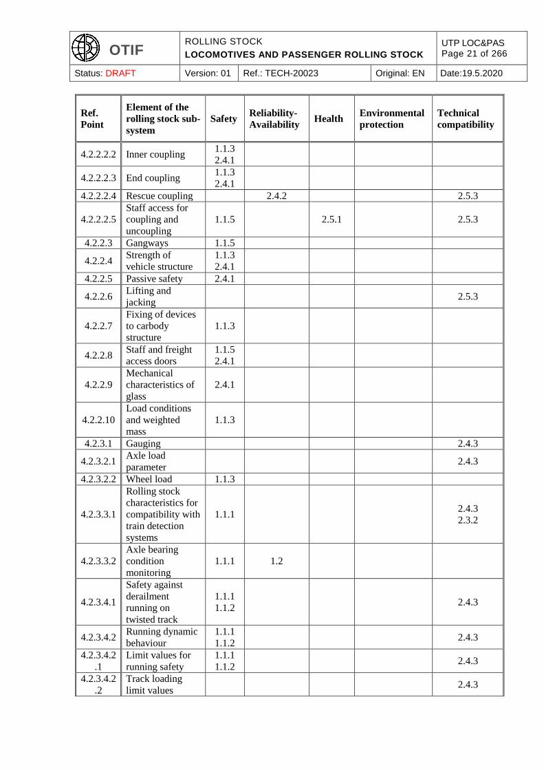
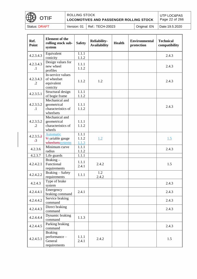
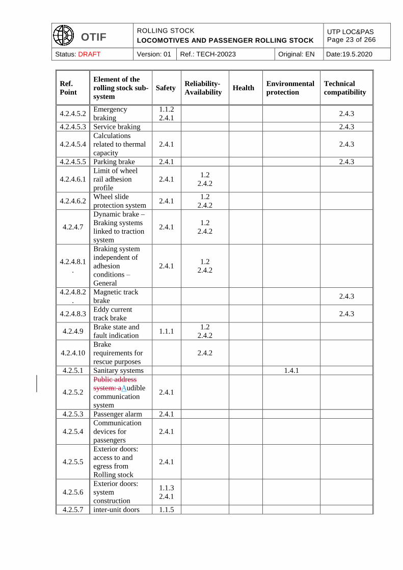
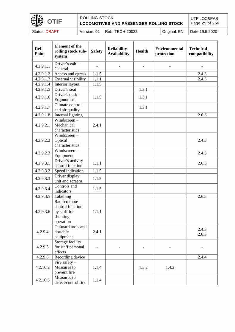
The following table indicates the essential requirements, as set out and numbered in
UTP GEN-A6, Annex III toof Directive (EU)
2016/7972008/57/EC,
taken into account by the specifications set out in Chapter 4 of this
UTP. TSI.
Rolling stock elements corresponding to essential requirements
Note: only points in section 4.2 which contain requirements are listed.
6 Essential requirements – General Provisions, UTP GEN-A , APTU (A 94-01A/1.2011)
OTIF ROLLING STOCK
LOCOMOTIVES AND PASSENGER ROLLING STOCK
UTP LOC&PAS Page 21 of 266
Status: DRAFT Version: 01 Ref.: TECH-20023 Original: EN Date:19.5.2020
Ref.
Point
Element of the
rolling stock sub-
system
Safety Reliability-
Availability Health
Environmental
protection
Technical
compatibility
4.2.2.2.2 Inner coupling 1.1.3
2.4.1
4.2.2.2.3 End coupling 1.1.3
2.4.1
4.2.2.2.4 Rescue coupling 2.4.2 2.5.3
4.2.2.2.5
Staff access for
coupling and
uncoupling
1.1.5 2.5.1 2.5.3
4.2.2.3 Gangways 1.1.5
4.2.2.4 Strength of
vehicle structure
1.1.3
2.4.1
4.2.2.5 Passive safety 2.4.1
4.2.2.6 Lifting and
jacking 2.5.3
4.2.2.7
Fixing of devices
to carbody
structure
1.1.3
4.2.2.8 Staff and freight
access doors
1.1.5
2.4.1
4.2.2.9
Mechanical
characteristics of
glass
2.4.1
4.2.2.10
Load conditions
and weighted
mass
1.1.3
4.2.3.1 Gauging 2.4.3
4.2.3.2.1 Axle load
parameter 2.4.3
4.2.3.2.2 Wheel load 1.1.3
4.2.3.3.1
Rolling stock
characteristics for
compatibility with
train detection
systems
1.1.1 2.4.3
2.3.2
4.2.3.3.2
Axle bearing
condition
monitoring
1.1.1 1.2
4.2.3.4.1
Safety against
derailment
running on
twisted track
1.1.1
1.1.2 2.4.3
4.2.3.4.2 Running dynamic
behaviour
1.1.1
1.1.2 2.4.3
4.2.3.4.2
.1
Limit values for
running safety
1.1.1
1.1.2 2.4.3
4.2.3.4.2
.2
Track loading
limit values 2.4.3
OTIF ROLLING STOCK
LOCOMOTIVES AND PASSENGER ROLLING STOCK
UTP LOC&PAS Page 22 of 266
Status: DRAFT Version: 01 Ref.: TECH-20023 Original: EN Date:19.5.2020
Ref.
Point
Element of the
rolling stock sub-
system
Safety Reliability-
Availability Health
Environmental
protection
Technical
compatibility
4.2.3.4.3 Equivalent
conicity
1.1.1
1.1.2 2.4.3
4.2.3.4.3
.1
Design values for
new wheel
profiles
1.1.1
1.1.2 2.4.3
4.2.3.4.3
.2
In-service values
of wheelset
equivalent
conicity
1.1.2 1.2 2.4.3
4.2.3.5.1 Structural design
of bogie frame
1.1.1
1.1.2
4.2.3.5.2
.1
Mechanical and
geometrical
characteristics of
wheelsets
1.1.1
1.1.2 2.4.3
4.2.3.5.2
.2
Mechanical and
geometrical
characteristics of
wheels
1.1.1
1.1.2
4.2.3.5.2
.3
Automatic
Vvariable gauge
wheelsetssystems
1.1.1
1.1.2
1.1.3
1.2 1.5
4.2.3.6 Minimum curve
radius
1.1.1
1.1.2 2.4.3
4.2.3.7 Life guards 1.1.1
4.2.4.2.1
Braking –
Functional
requirements
1.1.1
2.4.1 2.4.2 1.5
4.2.4.2.2 Braking – Safety
requirements 1.1.1
1.2
2.4.2
4.2.4.3 Type of brake
system 2.4.3
4.2.4.4.1 Emergency
braking command 2.4.1 2.4.3
4.2.4.4.2 Service braking
command 2.4.3
4.2.4.4.3 Direct braking
command 2.4.3
4.2.4.4.4 Dynamic braking
command 1.1.3
4.2.4.4.5 Parking braking
command 2.4.3
4.2.4.5.1
Braking
performance –
General
requirements
1.1.1
2.4.1 2.4.2 1.5
OTIF ROLLING STOCK
LOCOMOTIVES AND PASSENGER ROLLING STOCK
UTP LOC&PAS Page 23 of 266
Status: DRAFT Version: 01 Ref.: TECH-20023 Original: EN Date:19.5.2020
Ref.
Point
Element of the
rolling stock sub-
system
Safety Reliability-
Availability Health
Environmental
protection
Technical
compatibility
4.2.4.5.2 Emergency
braking
1.1.2
2.4.1 2.4.3
4.2.4.5.3 Service braking 2.4.3
4.2.4.5.4
Calculations
related to thermal
capacity
2.4.1 2.4.3
4.2.4.5.5 Parking brake 2.4.1 2.4.3
4.2.4.6.1
Limit of wheel
rail adhesion
profile
2.4.1 1.2
2.4.2
4.2.4.6.2 Wheel slide
protection system 2.4.1
1.2
2.4.2
4.2.4.7
Dynamic brake –
Braking systems
linked to traction
system
2.4.1 1.2
2.4.2
4.2.4.8.1
.
Braking system
independent of
adhesion
conditions –
General
2.4.1 1.2
2.4.2
4.2.4.8.2
.
Magnetic track
brake 2.4.3
4.2.4.8.3 Eddy current
track brake 2.4.3
4.2.4.9 Brake state and
fault indication 1.1.1
1.2
2.4.2
4.2.4.10
Brake
requirements for
rescue purposes
2.4.2
4.2.5.1 Sanitary systems 1.4.1
4.2.5.2
Public address
system: aAudible
communication
system
2.4.1
4.2.5.3 Passenger alarm 2.4.1
4.2.5.4
Communication
devices for
passengers
2.4.1
4.2.5.5
Exterior doors:
access to and
egress from
Rolling stock
2.4.1
4.2.5.6
Exterior doors:
system
construction
1.1.3
2.4.1
4.2.5.7 inter-unit doors 1.1.5

OTIF ROLLING STOCK
LOCOMOTIVES AND PASSENGER ROLLING STOCK
UTP LOC&PAS Page 24 of 266
Status: DRAFT Version: 01 Ref.: TECH-20023 Original: EN Date:19.5.2020
Ref.
Point
Element of the
rolling stock sub-
system
Safety Reliability-
Availability Health
Environmental
protection
Technical
compatibility
4.2.5.8 Internal air
quality 1.3.2
4.2.5.9 body side
windows 1.1.5
4.2.6.1 Environmental
conditions 2.4.2
4.2.6.2.1
Slipstream effects
on passengers on
platform and on
workers at track
side
1.1.1 1.3.1
4.2.6.2.2 Head pressure
pulse 2.4.3
4.2.6.2.3
Maximum
pressure
variations in
tunnels
2.4.3
4.2.6.2.4 Cross wind 1.1.1
4.2.6.2.
5
Aerodynamic
effect on
ballasted track
1.1.1 2.4.3
4.2.7.1.1 Head lights 2.4.3
4.2.7.1.2 Marker lights 1.1.1 2.4.3
4.2.7.1.3 Tail lights 1.1.1 2.4.3
4.2.7.1.4 Lamp controls 2.4.3
4.2.7.2.1 Horn – General 1.1.1 2.4.3
2.6.3
4.2.7.2.2
Warning horn
sound pressure
levels
1.1.1 1.3.1
4.2.7.2.3 Protection 2.4.3
4.2.7.2.4 Horn control 1.1.1 2.4.3
4.2.8.1 Traction
performance
2.4.3
2.6.3
4.2.8.2
4.2.8.2.1
to
4.2.8.2.9
Power supply
1.5
2.4.3
2.2.3
4.2.8.2.1
0
Electrical
protection of the
train
2.4.1
4.2.8.3
Diesel and other
thermal traction
system
2.4.1 1.4.1
4.2.8.4 Protection against
electrical hazards 2.4.1
OTIF ROLLING STOCK
LOCOMOTIVES AND PASSENGER ROLLING STOCK
UTP LOC&PAS Page 25 of 266
Status: DRAFT Version: 01 Ref.: TECH-20023 Original: EN Date:19.5.2020
Ref.
Point
Element of the
rolling stock sub-
system
Safety Reliability-
Availability Health
Environmental
protection
Technical
compatibility
4.2.9.1.1 Driver’s cab –
General - - - - -
4.2.9.1.2 Access and egress 1.1.5 2.4.3
4.2.9.1.3 External visibility 1.1.1 2.4.3
4.2.9.1.4 Interior layout 1.1.5
4.2.9.1.5 Driver's seat 1.3.1
4.2.9.1.6 Driver's desk –
Ergonomics 1.1.5 1.3.1
4.2.9.1.7 Climate control
and air quality 1.3.1
4.2.9.1.8 Internal lighting 2.6.3
4.2.9.2.1
Windscreen –
Mechanical
characteristics
2.4.1
4.2.9.2.2
Windscreen –
Optical
characteristics
2.4.3
4.2.9.2.3 Windscreen –
Equipment 2.4.3
4.2.9.3.1 Driver´s activity
control function 1.1.1 2.6.3
4.2.9.3.2 Speed indication 1.1.5
4.2.9.3.3 Driver display
unit and screens 1.1.5
4.2.9.3.4 Controls and
indicators 1.1.5
4.2.9.3.5 Labelling 2.6.3
4.2.9.3.6
Radio remote
control function
by staff for
shunting
operation
1.1.1
4.2.9.4
Onboard tools and
portable
equipment
2.4.1 2.4.3
2.6.3
4.2.9.5
Storage facility
for staff personal
effects
- - - - -
4.2.9.6 Recording device 2.4.4
4.2.10.2
Fire safety –
Measures to
prevent fire
1.1.4 1.3.2 1.4.2
4.2.10.3 Measures to
detect/control fire 1.1.4
OTIF ROLLING STOCK
LOCOMOTIVES AND PASSENGER ROLLING STOCK
UTP LOC&PAS Page 26 of 266
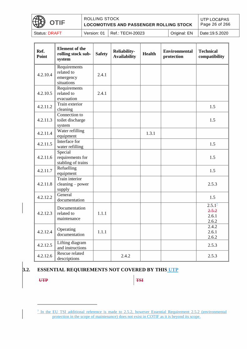
Status: DRAFT Version: 01 Ref.: TECH-20023 Original: EN Date:19.5.2020
Ref.
Point
Element of the
rolling stock sub-
system
Safety Reliability-
Availability Health
Environmental
protection
Technical
compatibility
4.2.10.4
Requirements
related to
emergency
situations
2.4.1
4.2.10.5
Requirements
related to
evacuation
2.4.1
4.2.11.2 Train exterior
cleaning 1.5
4.2.11.3
Connection to
toilet discharge
system
1.5
4.2.11.4 Water refilling
equipment 1.3.1
4.2.11.5 Interface for
water refilling 1.5
4.2.11.6
Special
requirements for
stabling of trains
1.5
4.2.11.7 Refuelling
equipment 1.5
4.2.11.8
Train interior
cleaning – power
supply
2.5.3
4.2.12.2 General
documentation 1.5
4.2.12.3
Documentation
related to
maintenance
1.1.1
2.5.17
2.5.2
2.6.1
2.6.2
4.2.12.4 Operating
documentation 1.1.1
2.4.2
2.6.1
2.6.2
4.2.12.5 Lifting diagram
and instructions 2.5.3
4.2.12.6 Rescue related
descriptions 2.4.2 2.5.3
3.2. ESSENTIAL REQUIREMENTS NOT COVERED BY THIS UTP
UTP TSI
7 In the EU TSI additional reference is made to 2.5.2, however Essential Requirement 2.5.2 (environmental
protection in the scope of maintenance) does not exist in COTIF as it is beyond its scope.
OTIF ROLLING STOCK
LOCOMOTIVES AND PASSENGER ROLLING STOCK
UTP LOC&PAS Page 27 of 266
Status: DRAFT Version: 01 Ref.: TECH-20023 Original: EN Date:19.5.2020
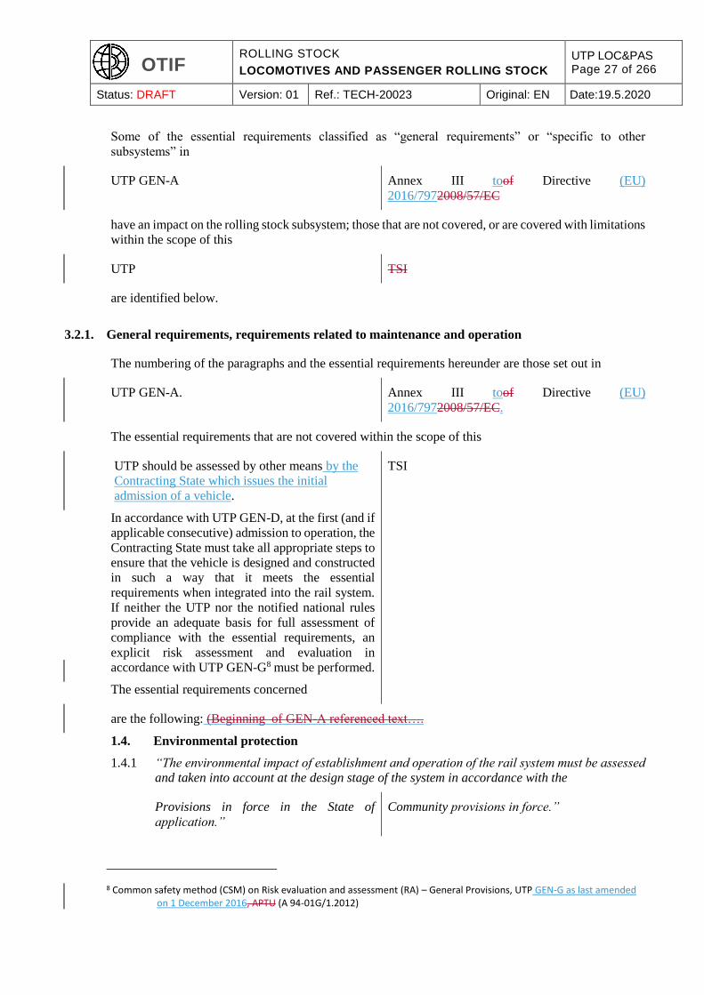
Some of the essential requirements classified as “general requirements” or “specific to other
subsystems” in
UTP GEN-A Annex III toof Directive (EU)
2016/7972008/57/EC
have an impact on the rolling stock subsystem; those that are not covered, or are covered with limitations
within the scope of this
UTP TSI
are identified below.
3.2.1. General requirements, requirements related to maintenance and operation
The numbering of the paragraphs and the essential requirements hereunder are those set out in
UTP GEN-A. Annex III toof Directive (EU)
2016/7972008/57/EC.
The essential requirements that are not covered within the scope of this
UTP should be assessed by other means by the
Contracting State which issues the initial
admission of a vehicle.
In accordance with UTP GEN-D, at the first (and if
applicable consecutive) admission to operation, the
Contracting State must take all appropriate steps to
ensure that the vehicle is designed and constructed
in such a way that it meets the essential
requirements when integrated into the rail system.
If neither the UTP nor the notified national rules
provide an adequate basis for full assessment of
compliance with the essential requirements, an
explicit risk assessment and evaluation in
accordance with UTP GEN-G8 must be performed.
The essential requirements concerned
TSI
are the following: (Beginning of GEN-A referenced text….
1.4. Environmental protection
1.4.1 “The environmental impact of establishment and operation of the rail system must be assessed
and taken into account at the design stage of the system in accordance with the
Provisions in force in the State of
application.”
Community provisions in force.”
8 Common safety method (CSM) on Risk evaluation and assessment (RA) – General Provisions, UTP GEN-G as last amended on 1 December 2016, APTU (A 94-01G/1.2012)
OTIF ROLLING STOCK
LOCOMOTIVES AND PASSENGER ROLLING STOCK
UTP LOC&PAS Page 28 of 266
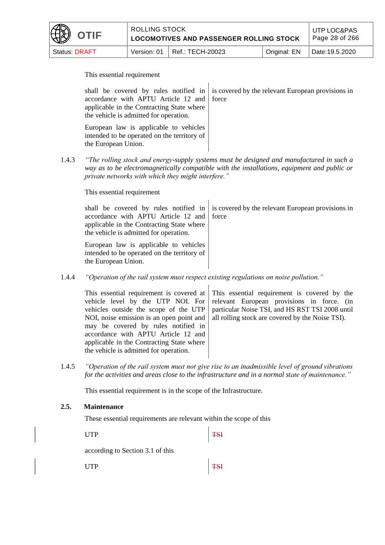
Status: DRAFT Version: 01 Ref.: TECH-20023 Original: EN Date:19.5.2020
This essential requirement
shall be covered by rules notified in
accordance with APTU Article 12 and
applicable in the Contracting State where
the vehicle is admitted for operation.
European law is applicable to vehicles
intended to be operated on the territory of
the European Union.
is covered by the relevant European provisions in
force
1.4.3 “The rolling stock and energy-supply systems must be designed and manufactured in such a
way as to be electromagnetically compatible with the installations, equipment and public or
private networks with which they might interfere.”
This essential requirement
shall be covered by rules notified in
accordance with APTU Article 12 and
applicable in the Contracting State where
the vehicle is admitted for operation.
European law is applicable to vehicles
intended to be operated on the territory of
the European Union.
is covered by the relevant European provisions in
force
1.4.4 “Operation of the rail system must respect existing regulations on noise pollution.”
This essential requirement is covered at
vehicle level by the UTP NOI. For
vehicles outside the scope of the UTP
NOI, noise emission is an open point and
may be covered by rules notified in
accordance with APTU Article 12 and
applicable in the Contracting State where
the vehicle is admitted for operation.
This essential requirement is covered by the
relevant European provisions in force. (in
particular Noise TSI, and HS RST TSI 2008 until
all rolling stock are covered by the Noise TSI).
1.4.5 “Operation of the rail system must not give rise to an inadmissible level of ground vibrations
for the activities and areas close to the infrastructure and in a normal state of maintenance.”
This essential requirement is in the scope of the Infrastructure.
2.5. Maintenance
These essential requirements are relevant within the scope of this
UTP TSI
according to Section 3.1 of this
UTP TSI
OTIF ROLLING STOCK
LOCOMOTIVES AND PASSENGER ROLLING STOCK
UTP LOC&PAS Page 29 of 266
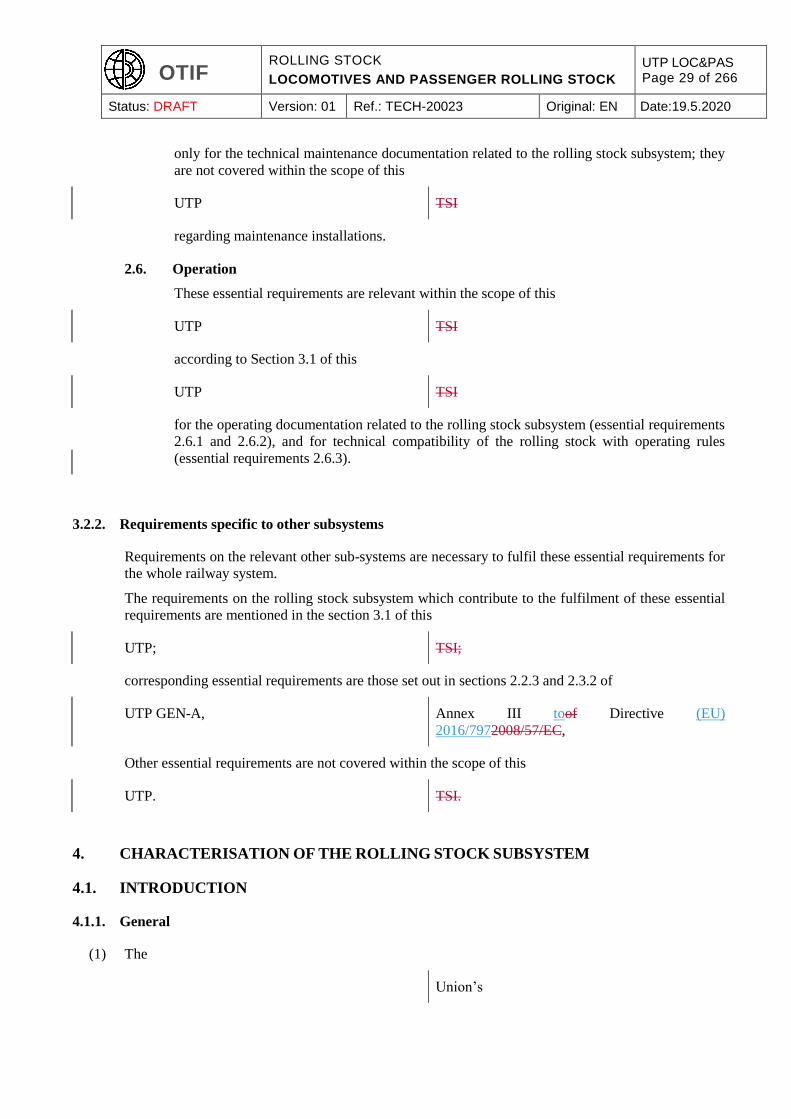
Status: DRAFT Version: 01 Ref.: TECH-20023 Original: EN Date:19.5.2020
only for the technical maintenance documentation related to the rolling stock subsystem; they
are not covered within the scope of this
UTP TSI
regarding maintenance installations.
2.6. Operation
These essential requirements are relevant within the scope of this
UTP TSI
according to Section 3.1 of this
UTP TSI
for the operating documentation related to the rolling stock subsystem (essential requirements
2.6.1 and 2.6.2), and for technical compatibility of the rolling stock with operating rules
(essential requirements 2.6.3).
3.2.2. Requirements specific to other subsystems
Requirements on the relevant other sub-systems are necessary to fulfil these essential requirements for
the whole railway system.
The requirements on the rolling stock subsystem which contribute to the fulfilment of these essential
requirements are mentioned in the section 3.1 of this
UTP; TSI;
corresponding essential requirements are those set out in sections 2.2.3 and 2.3.2 of
UTP GEN-A, Annex III toof Directive (EU)
2016/7972008/57/EC,
Other essential requirements are not covered within the scope of this
UTP. TSI.
4. CHARACTERISATION OF THE ROLLING STOCK SUBSYSTEM
4.1. INTRODUCTION
4.1.1. General
(1) The
Union’s
OTIF ROLLING STOCK
LOCOMOTIVES AND PASSENGER ROLLING STOCK
UTP LOC&PAS Page 30 of 266
Status: DRAFT Version: 01 Ref.: TECH-20023 Original: EN Date:19.5.2020
rail system, to which
APTU and ATMF apply, is defined by means of
subsystems as set out in UTP GEN-B. The
consistency between the different subsystems
Directive (EU) 2016/7972008/57/EC applies and
of which the rolling stock subsystem is a part, is
an integrated system whose consistency
needs to be verified. This consistency must be checked in particular with regard to the specifications of
the rolling stock subsystem, its interfaces with the other subsystems
of the Union’s rail system in which it is integrated,
as well as the operating and maintenance rules.
(2) The basic parameters of the rolling stock sub-system are defined in the present Chapter 4 of this
UTP. TSI.
(3) Except where this is strictly necessary for
international traffic, the interoperability of the Union’s rail system,
the functional and technical specifications of the subsystem and its interfaces described in Sections 4.2
and 4.3, do not impose the use of specific technologies or technical solutions.
(4) Some of the rolling stock characteristics that are mandated to be recorded in the
Registers, according to Article 13§1 of ATMF “European register of authorised types of
vehicles” (according to the relevant Commission
Decision)
are described in Sections 4.2 and 6.2 of this
UTP. TSI.
Additionally, these characteristics are required to be provided in the rolling stock technical
documentation described in point 4.2.12 of this
UTP. TSI.
4.1.2. Description of the Rolling stock subject to the application of this
UTP TSI
(1) Rolling stock subject to the application of this
UTP TSI
(designated as a unit in the context of this
UTP) TSI)
OTIF ROLLING STOCK
LOCOMOTIVES AND PASSENGER ROLLING STOCK
UTP LOC&PAS Page 31 of 266
Status: DRAFT Version: 01 Ref.: TECH-20023 Original: EN Date:19.5.2020
shall be described in the
UTP certificate of verification in accordance with
UTP GEN-D,
certificate of “EC” verification,
using one of the following characteristics:
Trainset in fixed formation and, when required, predefined formation(s) of several trainsets of
the type under assessment for multiple operation.
Single vehicle or fixed rakes of vehicles intended for predefined formation(s).
Single vehicle or fixed rakes of vehicles intended for general operation and when required,
predefined formation(s) of several vehicles (locomotives) of the type under assessment for
multiple operation.
Note: Multiple operation of the unit under assessment with other types of rolling stock is not in the
scope of this
UTP. TSI.
(2) Definitions related to train formation and units are given in Section 2.2 of this
UTP. TSI.
(3) When a unit intended for use in fixed or predefined formation(s) is assessed, the formation(s) for which
such assessment is valid shall be defined by the party asking for assessment, and stated in the
UTP certificate of verification. certificate of “EC” verification.
The definition of each formation shall include the type designation of each vehicle (or of vehicle bodies
and wheelsets in case of articulated fixed formation), and their arrangement in the formation. Additional
details are given in clauses 6.2.8 & 9.
(4) Some characteristics or some assessments of a unit intended to be used in general operation, will require
defined limits regarding the train formations. These limits are laid down in Section 4.2 and in clause
6.2.7.
4.1.3. Main categorisation of the rolling stock for application of
UTP TSI
Requirements
(1) A rolling stock technical categorisation system is used in the following clauses of this
UTP TSI
to define relevant requirements applicable to a unit.
(2) The technical category(ies) relevant for the unit subject to the application of this

OTIF ROLLING STOCK
LOCOMOTIVES AND PASSENGER ROLLING STOCK
UTP LOC&PAS Page 32 of 266
Status: DRAFT Version: 01 Ref.: TECH-20023 Original: EN Date:19.5.2020
UTP TSI
shall be identified by the party asking for assessment. This categorisation shall be used by the
assessing entity notified body
in charge of the assessment, in order to assess the applicable requirements from this
UTP, TSI,
and shall be stated in the
UTP certificate of verification. certificate of “EC” verification.
(3) The technical categories of rolling stock are the following:
Unit designed to carry passengers
Unit designed to carry passenger-related load (luggage, cars, etc.)
Unit designed to carry other payload (mail, freight, etc.) in self-propelling trains
Unit fitted with a driver’s cab
Unit fitted with traction equipment
Electric unit, defined as a unit supplied with electric energy by electrification system(s)
with an overhead contact line. specified in the ENE TSI.
Thermal traction unit
Freight locomotive: Unit designed to haul freight wagons
Passenger locomotive: Unit designed to haul passenger carriages
OTMs
Infrastructure inspection vehicles.
A unit is characterised by one or several of the categories above.
(4) Unless stated otherwise in the clauses of Section 4.2, requirements specified in this
UTP TSI
apply to all technical categories of rolling stock defined above.
(5) The unit operational configuration shall also be considered when it is assessed; a distinction shall be
made between:
A unit that can be operated as a train.
A unit that cannot be operated alone, and that has to be coupled with other unit(s) to be operated
as a train (see also clauses 4.1.2, 6.2.7 and 6.2.8).
(6) The maximum design speed of the unit subject to the application of this
OTIF ROLLING STOCK
LOCOMOTIVES AND PASSENGER ROLLING STOCK
UTP LOC&PAS Page 33 of 266
Status: DRAFT Version: 01 Ref.: TECH-20023 Original: EN Date:19.5.2020
UTP TSI
shall be declared by the party asking for assessment; it shall be a multiple of 5 km/h (see also clause
4.2.8.1.2) when its value is higher than 60 km/h; it shall be used by the
assessing entity notified body
in charge of the assessment, in order to assess the applicable requirements from this
UTP, TSI,
and shall be stated in the
UTP certificate of verification. certificate of “EC” verification.
4.1.4. Categorisation of the rolling stock for fire safety
(1) In respect of fire safety requirements, four categories of rolling stock are defined
, which are specified as: and specified in the SRT TSI:
Category A passenger rolling stock (including passenger locomotive),
Category B passenger rolling stock (including passenger locomotive),
Freight locomotive, and self-propelling unit designed to carry other payload than passenger
(mail, freight, infrastructure inspection vehicle, etc.),
OTMs.
(2) The compatibility between the category of the unit and its operation in tunnels
is presumed to be defined in each Contracting State
by the competent authority in such a way that for
each tunnel on lines used for international traffic it
is specified which category of rolling stock, in
accordance with this UTP, may be operated in the
tunnel. When defining this compatibility, the
competent authority shall observe the principle that
rolling stock of category B of tunnel safety (highest
category) is permitted to run in all tunnels, and
rolling stock of category A is permitted to run in
tunnels with a length of 5 km (or less), without
prejudice to specific cases.
The measures for running capability specified in
point 4.2.10.4.4 permit trains of category B to
continue running for 15 minutes and to reach a safe
area within 20 km, assuming the train is able to run
at 80 km/h. If it is not possible for the train to leave
the tunnel, it will be evacuated using the
infrastructure facilities (safe area) provided in the
tunnel.
is set out in the SRT TSI
OTIF ROLLING STOCK
LOCOMOTIVES AND PASSENGER ROLLING STOCK
UTP LOC&PAS Page 34 of 266
Status: DRAFT Version: 01 Ref.: TECH-20023 Original: EN Date:19.5.2020
The competent authority shall ensure that a tunnel
emergency plan, including the relevant evacuation
procedures, is available.
(3) For units designed to carry passengers or haul passenger carriages, and subject to the application of this
UTP, TSI,
category A is the minimum category to be selected by the party asking for assessment;
units designed to carry passengers and to be
operated in tunnels with a length of more than 5 km
shall be assessed against the requirements
applicable to category B.
the criteria for selecting category B are given in
the SRT TSI.
(4) This categorisation shall be used by the
assessing entity notified body
in charge of the assessment, in order to assess the applicable requirements from the clause 4.2.10 of this
UTP TSI
and shall be stated in the
UTP certificate of verification. certificate of “EC” verification.
4.2. Functional and technical specification of the sub-system
4.2.1. General
4.2.1.1. Breakdown
(1) The functional and technical specifications of the rolling stock subsystem are grouped and sorted out in
the following clauses of this section:
Structures and mechanical parts
Track interaction and gauging
Braking
Passenger related items
Environmental conditions
External lights & audible and visible warning devices
Traction and electrical equipment
Driver’s cab and driver-machine interface
Fire safety and evacuation
Servicing
Documentation for operation and maintenance

OTIF ROLLING STOCK
LOCOMOTIVES AND PASSENGER ROLLING STOCK
UTP LOC&PAS Page 35 of 266
Status: DRAFT Version: 01 Ref.: TECH-20023 Original: EN Date:19.5.2020
(2) For particular technical aspects specified in chapters 4, 5 and 6, the functional and technical
specification makes an explicit reference to a clause of an EN standard or other technical document,
as allowed by Article 54(8) of Directive (EU)
2016/7972008/57/EC;
these references are listed in the Appendix J of this
UTP. TSI.
(3) Information needed on board for the train staff to be aware of the operational state of the train (normal
state, equipment out of order, degraded situation ...) are described in the clause dealing with the relevant
function, and in clause 4.2.12 “documentation for the operation and maintenance”.
4.2.1.2. Open points
(1) When, for a particular technical aspect, the functional and technical specification necessary to meet the
essential requirements has not been yet developed, and therefore is not included in this
UTP, TSI,
this aspect is identified as an open point in the relevant clause; Appendix I of this
UTP TSI
lists all open points, as required in
Article 8§7 of APTU. Article 54(6) of Directive (EU)
2016/7972008/57/EC.
The Appendix I mentions also if the open points relate to technical compatibility with the network; for
this purpose, the Appendix I is split in 2 parts:
Open points that relate to technical compatibility between the vehicle and the network.
Open points that do not relate to technical compatibility between the vehicle and the network.
(2) As required in
APTU Article 12 § 2 and ATMF Article 7 § 2, Articles 54(6) and 173(32) of Directive (EU)
2016/7972008/57/EC,
open points shall be addressed by the application of national technical rules.
4.2.1.3. Safety aspects
(1) The functions that are essential to safety are identified in Section 3.1 of this
UTP TSI
by their link to the essential requirements “safety”.
OTIF ROLLING STOCK
LOCOMOTIVES AND PASSENGER ROLLING STOCK
UTP LOC&PAS Page 36 of 266
Status: DRAFT Version: 01 Ref.: TECH-20023 Original: EN Date:19.5.2020
(2) Safety requirements related to these functions are covered by the technical specifications expressed in
the corresponding clause of Section 4.2 (e.g. “passive safety”, “wheels” ...).
(3) Where these technical specifications need to be complemented by requirements expressed in terms of
safety requirements (severity level), they are also specified in the corresponding clause of Section 4.2.
(4) Electronic devices and software, which are used to fulfil functions essential to safety shall be developed
and assessed according to a methodology adequate for safety related electronic devices and software.
4.2.2. Structure and mechanical parts
4.2.2.1. General
(1) This part addresses requirements relating to the design of vehicle structural body (strength of vehicle
structure) and of the mechanical links (mechanical interfaces) between vehicles or between units.
(2) Most of these requirements aim at ensuring the train’s mechanical integrity in operation and rescue
operation as well as protecting passenger and staff compartments in the event of collision or derailment.
4.2.2.2. Mechanical interfaces
4.2.2.2.1 General and definitions
In order to form a train (as defined in section 2.2) vehicles are coupled together in a way that enables
them to be operated together. The coupling is the mechanical interface that enables this. There are
several types of couplings:
(1) “Inner” coupling (also called “intermediate” coupling) is the coupling device between vehicles in order
to form a unit composed of several vehicles (e.g. a fixed rake of coaches or a trainset)
(2) End coupling (“external” coupling) of units is the coupling device used to couple together two (or
several) units to form a train. An end coupling can be ‘automatic’, ‘semi-automatic’ or ‘manual’. An
end coupling can be used for rescue purpose (see clause 4.2.2.2.4). In the context of this
UTP TSI
a ’Manual’ coupling is an end coupling system which requires (one or several) person(s) to stand
between the units to be coupled or uncoupled for the mechanical coupling of these units.
(3) Rescue coupling is the coupling device that enables a unit to be rescued by a recovery power unit
equipped with a ’standard’ manual coupling as per clause 4.2.2.2.3 where the unit to be rescued is
equipped with a different coupling system or is not equipped with any coupling system.
4.2.2.2.2 Inner coupling
(1) Inner couplings between the different vehicles (fully supported by their own wheels) of a unit shall
incorporate a system capable of withstanding the forces due to the intended operating conditions.
OTIF ROLLING STOCK
LOCOMOTIVES AND PASSENGER ROLLING STOCK
UTP LOC&PAS Page 37 of 266
Status: DRAFT Version: 01 Ref.: TECH-20023 Original: EN Date:19.5.2020
(2) Where the inner coupling system between vehicles has a lower longitudinal strength than the end
coupling(s) of the unit, provisions shall be made to rescue the unit in case of breakage of any such inner
coupling; these provisions shall be described in the documentation required in clause 4.2.12.6.
(3) In case of articulated units, the joint between two vehicles sharing the same running gear shall comply
with the requirements of the specification referenced in Appendix J-1, index 1.
4.2.2.2.3 End coupling
a) General Requirements
a-1) requirements on characteristics of end coupling
(1) Where an end coupling is provided at any end of a unit, the following requirements apply to all types
of end coupling (automatic, semi-automatic or manual):
End couplings shall incorporate a resilient coupling system, capable of withstanding the forces
due to the intended operational and rescue conditions.
The type of mechanical end coupling together with its nominal maximum design values of tensile
and compressive forces and the height above rail level of its centre line (unit in working order
with new wheels) shall be recorded in the technical documentation described in clause 4.2.12.
(2) Where there is no coupling at any end of a unit, a device to allow a rescue coupling shall be provided
at such end of the unit.
a-2) requirements on type of end coupling
(1) Units assessed in fixed or predefined formation, and of maximum design speed higher or equal to
250 km/h, shall be equipped at each end of the formation with an automatic centre buffer coupler
geometrically and functionally compatible with a “Type 10 latch system automatic centre buffer
coupler” (as defined in clause 5.3.1); the height above rail of its coupling centre line shall be 1025 mm
+ 15 mm /- 5 mm (measured with new wheels in load condition “design mass in working order”).
(2) Units designed and assessed for general operation and designed to be operated solely on the 1520 mm
system shall be fitted with a centre buffer coupler geometrically and functionally compatible with a
“SA3 coupling”; the height above rail of its coupling centre line shall be between 980 to 1080 mm (for
all wheel and load conditions).
b) Requirements on “Manual” coupling system
b-1) Provisions to units
(1) The following provisions apply specifically to units fitted with a “Manual” coupling system:
The coupling system shall be designed so that no human presence between the units to be coupled
/ uncoupled is required whilst either one is moving.
For units designed and assessed to be operated in ‘general operation’ or in ‘predefined
formation’, and fitted with a manual coupling system, this coupling system shall be of UIC type
(as defined in clause 5.3.2).

OTIF ROLLING STOCK
LOCOMOTIVES AND PASSENGER ROLLING STOCK
UTP LOC&PAS Page 38 of 266
Status: DRAFT Version: 01 Ref.: TECH-20023 Original: EN Date:19.5.2020
(2) These units shall comply with the additional requirements of point b-2) below.
b-2) Compatibility between units
On units equipped with manual coupling system of UIC type (as described in clause 5.3.2) and
pneumatic brake system compatible with UIC type (as described in clause 4.2.4.3), the following
requirements apply:
(1) The buffers and the screw coupling shall be installed according to clauses 5 and 6 of the specification
referenced in Appendix J-1, index 110 A.1 to A.3 of Appendix A.
(2) The dimensions and layout of brake pipes and hoses, couplings and cocks shall meet the following
requirements set in clauses 7 and 8 of the specification referenced in Appendix J-1, index 110.:
The interface of the brake pipe and main reservoir pipe shall be as set out in the specification
referenced in Appendix J-1, index 2.
The opening of the automatic air brake coupling head shall face the left when looking at the end
of the vehicle.
The opening of the main reservoir coupling head shall face the right when looking at the end of
the unit.
The end cocks shall be in accordance with the specification referenced in Appendix J-1, index 3.
The lateral location of brake pipes and cocks shall be compatible with the requirements of the
specification referenced in Appendix J-1, index 4.
4.2.2.2.4 Rescue coupling
(1) Provisions shall be made to enable the recovery of the line in case of breakdown by hauling or propelling
the unit to be rescued.
(2) Where the unit to be rescued is fitted with an end coupling, rescue shall be possible by means of a power
unit equipped with the same type of end coupling system (including compatible height above rail level
of its centre line).
(3) For all units, rescue shall be possible by means of a recovery unit i.e. a power unit featuring at each of
its ends intended to be used for rescue purposes:
a) On 1435 mm, 1524 mm, 1600 mm or 1668 mm systems:
A manual coupling system of UIC type (as described in clauses 4.2.2.2.3 and 5.3.2) and
pneumatic brake system of UIC type (as described in clause 4.2.4.3),
Lateral location of brake pipes and cocks according to the specification referenced in Appendix
J-1, index 5,
A free space of 395 mm above the centre line of the hook to allow the fitting of the rescue adaptor
as described below.
b) On 1520 mm system:
A centre buffer coupler geometrically and functionally compatible with a “SA3 coupling”; the
height above rail of its coupling centre line being between 980 to 1080 mm (for all wheel and
load conditions).
OTIF ROLLING STOCK
LOCOMOTIVES AND PASSENGER ROLLING STOCK
UTP LOC&PAS Page 39 of 266
Status: DRAFT Version: 01 Ref.: TECH-20023 Original: EN Date:19.5.2020
This is achieved either by means of a permanently installed compatible coupling system or through a
rescue coupler (also called rescue adaptor). In the latter case, the unit assessed against this
UTP TSI
shall be designed so that it is possible to carry the rescue coupler on-board.
(4) The rescue coupler (as defined in clause 5.3.3) shall comply with the following requirements:
To be designed to allow the rescue at a speed of at least 30 km/h;
To be secured after mounting onto the recovery unit in a way that prevents it coming off during
the rescue operation;
To withstand the forces due to the intended rescuing conditions;
To be designed such that it does not require any human presence between the recovery unit and
the unit to be rescued whilst either one is moving;
Neither the rescue coupler nor any braking hose shall limit the lateral movement of the hook
when fitted onto the recovery unit.
(5) The brake requirement for rescue purpose is covered by the clause 4.2.4.10 of this
UTP. TSI.
4.2.2.2.5 Staff access for coupling and uncoupling
(1) Units and end coupling-systems shall be designed so that staff is not exposed to undue risk during
coupling and uncoupling, or rescue operations.
(2) To comply with this requirement, units fitted with manual coupling systems of UIC type as per clause
4.2.2.2.3 b) shall comply with the following requirements (the ‘Bern rectangle’):
c) On 1435 mm, 1524 mm, 1600 mm or 1668 mm systems:
On units equipped with screw couplers and side buffers, the space for staff operation shall be in
accordance to the specification referenced in Appendix J-1, index 6.
Where a combined automatic and screw coupler is fitted it is permissible for the auto coupler
head to infringe the Berne rectangle on the left hand side when it is stowed and the screw coupler
is in use.
There shall be a handrail under each buffer. The handrails shall withstand a force of 1.5 kN.
(3) The operating and rescue documentation specified in clauses 4.2.12.4 and 4.2.12.6 shall describe
measures that are necessary to meet this requirement. Member States may also require application of
those requirements.
4.2.2.3. Gangways
(1) Where a gangway is provided as a means for passengers to circulate from one coach or one trainset to
another, it shall accommodate all relative movements of vehicles in normal operation without exposing
passengers to undue risk.
OTIF ROLLING STOCK
LOCOMOTIVES AND PASSENGER ROLLING STOCK
UTP LOC&PAS Page 40 of 266
Status: DRAFT Version: 01 Ref.: TECH-20023 Original: EN Date:19.5.2020
(2) Where operation with the gangway not being connected is foreseen, it shall be possible to prevent access
by passengers to the gangway.
(3) Requirements related to the gangway door when the gangway is not in use are specified in clause 4.2.5.7
“Passenger related items – Inter-unit doors”.
(4) Additional requirements are expressed in
the UTP PRM. the PRM TSI.
(5) These requirements of this clause do not apply to the end of vehicles where this area is not intended for
regular use by passengers.
4.2.2.4. Strength of vehicle structure
(1) This clause applies to all units except OTMs.
(2) For OTMs, alternative requirements to those expressed in this clause for static load, category and
acceleration are set out in Appendix C, clause C.1.
(3) The static and dynamic strength (fatigue) of vehicle bodies is relevant to ensure the safety required for
the occupants and the structural integrity of the vehicles in train and in shunting operations. Therefore,
the structure of each vehicle shall comply with the requirements of the specification referenced in
Appendix J-1, index 7. The rolling stock categories to be taken into account shall correspond to category
L for locomotives and power head units and categories PI or PII for all other types of vehicle within the
scope of this
UTP, TSI,
as defined in the specification referenced in Appendix J-1, index 7, clause 5.2.
(4) Proof of the strength of the vehicle body may be demonstrated by calculations and/or by testing,
according to the conditions set up in the specification referenced in Appendix J-1, index 7, clause 9.2.
(5) In case of a unit designed for higher compressive force than those of the categories (required above as
a minimum) in the specification referenced in Appendix J-1, index 7, this specification does not cover
the proposed technical solution; it is then permissible to use for compressive force other normative
documents that are publicly available.
In that case it shall be verified by the
assessing entity notified body
that the alternative normative documents form part of a technically consistent set of rules applicable to
the design, construction and testing of the vehicle structure.
The value of compressive force shall be recorded in the technical documentation defined in clause
4.2.12.
(6) The load conditions considered shall be consistent with those defined in clause 4.2.2.10 of this
UTP. TSI.
OTIF ROLLING STOCK
LOCOMOTIVES AND PASSENGER ROLLING STOCK
UTP LOC&PAS Page 41 of 266
Status: DRAFT Version: 01 Ref.: TECH-20023 Original: EN Date:19.5.2020
(7) The assumptions for aerodynamic loading shall be those described in clause 4.2.6.2.2 of this
UTP TSI
(passing of 2 trains).
(8) Joining techniques are covered by the above requirements. A verification procedure shall exist to ensure
at the production phase that defects that may decrease the mechanical characteristics of the structure are
controlled.
4.2.2.5. Passive safety
(1) The requirements specified in this clause apply to all units, except to units not intended to carry
passengers or staff during operation and except to OTMs.
(2) For units designed to be operated on the 1520 mm system, the requirements on passive safety described
in this clause are of voluntary application. If the Applicant chooses to apply the requirements on passive
safety described in this clause, this shall be recognised by Member States. Member States may also
require application of those requirements.
(3) For locomotives designed to be operated on the 1524 mm system, the requirements on passive safety
described in this clause are of voluntary application. If the Applicant chooses to apply the requirements
on passive safety described in this clause, this shall be recognised by Member States.
(4) Units which cannot operate up to the collision speeds specified under any of the collision scenarios
below are exempted from the provisions related to that collision scenario.
(5) Passive safety is aimed at complementing active safety when all other measures have failed. For this
purpose, the mechanical structure of vehicles shall provide protection of the occupants in the event of a
collision by providing means of:
limiting deceleration
maintaining survival space and structural integrity of the occupied areas
reducing the risk of overriding
reducing the risk of derailment
limiting the consequences of hitting a track obstruction.
To meet these functional requirements, units shall comply with the detailed requirements specified in
the specification referenced in Appendix J-1, index 8 related to crashworthiness design category C-I (as
per the specification referenced in Appendix J-1, index 8, Table 1 section 4), unless specified otherwise
below.
The following four reference collision scenarios shall be considered:
scenario 1: A front end impact between two identical units;,
scenario 2: A front end impact with a freight wagon;,
scenario 3: An impact of the unit with a large road vehicle on a level crossing;,
scenario 4: An impact of the unit into a low obstacle (e.g. car on a level crossing, animal, rock
etc.).

OTIF ROLLING STOCK
LOCOMOTIVES AND PASSENGER ROLLING STOCK
UTP LOC&PAS Page 42 of 266
Status: DRAFT Version: 01 Ref.: TECH-20023 Original: EN Date:19.5.2020
(6) Within the scope of the present
UTP, TSI,
‘Table 2 application rules’ in the specification referenced in point (5) above are completed by the
following: the application of requirements related to scenarios 1 and 2 to locomotives:
fitted with automatic end centre buffer couplers,
and capable of a traction effort higher than 300 kN
is an open point.
Note: such high traction effort is required for heavy haul freight locomotives.
(7) Due to their specific architecture, it is permitted for locomotives with single “central cab” as an
alternative method to demonstrate compliance against the requirement of scenario 3 by demonstrating
compliance with following criteria:
the frame of the locomotive is designed according to the specification referenced in Appendix J-
1, index 8 cat L (as already specified in clause 4.2.2.4 of this
UTP). TSI).
the distance between buffers and windscreen cab is at least 2,5 m.
(8)(6) These scenarios are described in the specification referenced in Appendix J-1, index 8, Table 2 of
section 5.
(9)(7) Within the scope of Tthe present
UTP, TSI,
specifies crashworthiness requirements applicable within its scope; therefore, the Annex A of the
specification referenced in Appendix J-1, index 8 shall not apply. The requirements of the specification
referenced in Appendix J-1, index 8 section 6 shall be applied in relation to the above given reference
collision scenarios.the “collision speed” and “collision partner” when scenarios 1 and 2 are applied to
locomotives fitted with automatic end centre buffer couplers and capable of a traction effort at coupling
higher than 300 kN described in Table 2 of the specification referenced in appendix J-1, index 8 shall
be:
20 km/h instead of 36 km/h for scenarios 1 and 2; and
the reference wagon described in appendix D instead of reference wagon described in annex C.1
of the specification referenced in appendix J-1, index 8 for scenario 2.
Note: such high traction effort is required for heavy haul freight locomotives.
(10)(8) To limit the consequences of hitting a track obstruction, the leading ends of locomotives, power heads,
driving coaches and trainsets shall be equipped with an obstacle deflector. The requirements with which
obstacle deflectors shall comply are defined in the specification referenced in Appendix J-1, index 8,
table 3 of section 5 and section 6.5.
OTIF ROLLING STOCK
LOCOMOTIVES AND PASSENGER ROLLING STOCK
UTP LOC&PAS Page 43 of 266
Status: DRAFT Version: 01 Ref.: TECH-20023 Original: EN Date:19.5.2020
4.2.2.6. Lifting and jacking
(1) This clause applies to all units.
(2) Additional provisions concerning the lifting and jacking of OTMs are specified in Appendix C, clause
C.2.
(3) It shall be possible to safely lift or jack each vehicle composing the unit, for recovery purposes
(following derailment or other accident or incident), and for maintenance purposes. To this purpose,
suitable vehicle body interfaces (lifting/jacking points) shall be provided, which permit the application
of vertical or quasi-vertical forces. The vehicle shall be designed for complete lifting or jacking,
including the running gear (e.g. by securing/attaching the bogies to the vehicle body). It shall also be
possible to lift or jack any end of the vehicle (including its running gear) with the other end resting on
the remaining running gear(s).
(4) It is recommended to design jacking points so that they can be used as lifting points with all the running
gears of the vehicle linked to the underframe of the vehicle.
(5) Jacking/Lifting points shall be located such as to enable the safe and stable lifting of the vehicle;
sufficient space shall be provided underneath and around each jacking point to allow an easy installation
of rescue devices. Jacking/Lifting points shall be designed such that staff is not exposed to any undue
risk under normal operation or when using the rescue equipments.
(6) When the lower structure of the bodyshell does not allow the provision of permanent built-in
jacking/lifting points, this structure shall be provided with fixtures which permit the fixation of
removable jacking/lifting points during the re-railing operation.
(7) The geometry of permanent built-in jacking/lifting points shall be compliant with the specification
referenced in Appendix J-1, index 9, clause 5.3; the geometry of removable jacking/lifting points shall
be compliant with the specification referenced in Appendix J-1, index 9, clause 5.4.
(8) Marking of lifting points shall be made by signs compliant with the specification referenced in
Appendix J-1, index 10.
(9) The structure shall be designed with consideration of the loads specified in the specification referenced
in Appendix J-1, index 11, clauses 6.3.2 and 6.3.3; proof of the strength of the vehicle body may be
demonstrated by calculations or by testing, according to the conditions set up in the specification
referenced in Appendix J-1, index 11, clause 9.2.
(10) Alternative normative documents may be used under the same conditions as defined in clause 4.2.2.4
above.
UTP. TSI.
Instructions shall be given as far as feasible by pictograms.
4.2.2.7. Fixing of devices to carbody structure
(1) This clause applies to all units, except to OTMs.
(2) Provisions concerning the structural strength of OTMs are specified in Appendix C, clause C.1.
OTIF ROLLING STOCK
LOCOMOTIVES AND PASSENGER ROLLING STOCK
UTP LOC&PAS Page 44 of 266
Status: DRAFT Version: 01 Ref.: TECH-20023 Original: EN Date:19.5.2020
(3) Fixed devices including those inside the passenger areas, shall be attached to the car body structure in
a way that prevents these fixed devices becoming loose and presenting a risk of passenger injuries or
lead to a derailment. To this aim, attachments of these devices shall be designed according to the
specification referenced in Appendix J-1, index 12, considering category L for locomotives and
category P-I or P-II for passenger rolling stock.
Alternative normative documents may be used under the same conditions as defined in clause 4.2.2.4
above.
4.2.2.8. Staff and freight access doors
(1) The doors for use of passengers are covered by the clause 4.2.5 of this
UTP: TSI:
“Passenger related items”. Cab doors are addressed in clause 4.2.9 of this
UTP. TSI.
This clause addresses doors for freight use and for use of train crew other than cab doors.
(2) Vehicles fitted with a compartment dedicated to train crew or freight shall be equipped with a device to
close and lock the doors. The doors shall remain closed and locked until they are intentionally released.
4.2.2.9. Mechanical characteristics of glass (other than windscreens)
(1) Where glass is used in glazing (including mirrors), it shall be either laminated or toughened glass which
is in accordance with one of the relevant publicly available standards suitable for railway application
with regard to the quality and area of use, thereby minimising the risk to passenger and staff being
injured by breaking glass.
4.2.2.10. Load conditions and weighed mass
(1) The following load conditions defined in the specification referenced in Appendix J-1, index 13, clause
2.14.5 shall be determined:
Design mass under exceptional payload
Design mass under normal payload
Design mass in working order
(2) The hypothesis taken for arriving at the load conditions above shall be justified and documented in the
general documentation described in clause 4.2.12.2 of this
UTP. TSI.
These hypothesis shall be based on a rolling stock categorisation (high speed and long distance train,
other) and on a payload description (passengers, payload per m² in standing and service areas)
consistent with the specification referenced in Appendix J-1, index 13; values for the different
parameters may deviate from this standard provided that they are justified.
OTIF ROLLING STOCK
LOCOMOTIVES AND PASSENGER ROLLING STOCK
UTP LOC&PAS Page 45 of 266
Status: DRAFT Version: 01 Ref.: TECH-20023 Original: EN Date:19.5.2020
(3) For OTMs, different load conditions (minimum mass, maximum mass) may be used, in order to take
into account optional on-board equipment.
(4) The conformity assessment procedure is described in clause 6.2.3.1 of this
UTP. TSI.
For each load condition defined above, the following information shall be provided in the technical
documentation described in clause 4.2.12:
Total vehicle mass (for each vehicle of the unit)
Mass per axle (for each axle)
Mass per wheel (for each wheel).
Note: for units equipped with independently rotating wheels, “axle” shall be interpreted as a
geometric notion, and not as a physical component; this is valid to the whole
UTP, TSI,
unless stated otherwise.
4.2.3. Track interaction and gauging
4.2.3.1. Gauging
(1) This clause concerns the rules for calculation and verification intended for sizing the rolling stock to
run on one or several infrastructures without interference risk.
For units designed to be operated on other track gauge(s) than 1520 mm system:
(2) The applicant shall select the intended reference profile including the reference profile for the lower
parts. This reference profile shall be recorded in the technical documentation defined in clause 4.2.12
of this
UTP. TSI.
(3) The compliance of a unit with this intended reference profile shall be established by one of the methods
set out in the specification referenced in Appendix J-1, index 14.
During a transitional period ending
on 31.12.2017, 3 years after the date of application of this TSI,
for technical compatibility with the existing national network it is permissible for the reference profile
of the unit to alternatively be established in accordance with the national technical rules notified for this
purpose.
This shall not prevent the access of
UTP TSI
compliant rolling stock to the national network.
OTIF ROLLING STOCK
LOCOMOTIVES AND PASSENGER ROLLING STOCK
UTP LOC&PAS Page 46 of 266
Status: DRAFT Version: 01 Ref.: TECH-20023 Original: EN Date:19.5.2020
(4) In case the unit is declared as compliant with one or several of the reference contours G1, GA, GB, GC
or DE3, including those related to the lower part GI1, GI2 or GI3, as set out in the specification
referenced in Appendix J-1, index 14, compliance shall be established by the kinematic method as set
out in the specification referenced in Appendix J-1, index 14.
The compliance to those reference contour(s) shall be recorded in the technical documentation defined
in clause 4.2.12 of this
UTP. TSI.
(5) For electric units, the pantograph gauge shall be verified by calculation according to the specification
referenced in Appendix J-1, index 14, clause A.3.12 to ensure that the pantograph envelope complies
with the mechanical kinematic pantograph gauge
of the networks on which the vehicle is intended to
be operated and to be defined by the applicant.
which in itself is determined according to
Appendix D of ENE TSI,
and depends on the choice made for the pantograph head geometry: the two permitted possibilities are
defined in clause 4.2.8.2.9.2 of this
UTP. TSI.
The voltage of the power supply is considered in the infrastructure gauge in order to ensure the proper
insulation distances between the pantograph and fixed installations.
(6) The pantograph sway
as as specified in clause 4.2.10 of ENE TSI and
used for the mechanical kinematic gauge calculation shall be justified by calculations or measurements
as set out in the specification referenced in Appendix J-1, index 14.
For units designed to be operated on track gauge of 1520 mm system:
(7) The static contour of the vehicle shall be within the ‘T’ uniform vehicle gauge; the reference contour
for infrastructure is the ‘S’ gauge. This contour is specified in Appendix B.
(8) For electric units the pantograph gauge shall be verified by calculation to ensure that the pantograph
envelope complies with the mechanical static pantograph gauge
of the networks on which the vehicle is intended to
be operated and to be defined by the applicant.;
which is defined in Appendix D of ENE TSI;
the choice made for the pantograph head geometry shall be taken into account: the permitted
possibilities are defined in clause 4.2.8.2.9.2 of this
UTP. TSI.
OTIF ROLLING STOCK
LOCOMOTIVES AND PASSENGER ROLLING STOCK
UTP LOC&PAS Page 47 of 266
Status: DRAFT Version: 01 Ref.: TECH-20023 Original: EN Date:19.5.2020
4.2.3.2. Axle load and wheel load
4.2.3.2.1. Axle load parameter
(1) The axle load is an interface parameter between the unit and the infrastructure. The axle load is a
performance parameter of the infrastructure
which should be specified by the Competent
Authority of the relevant Contracting States in such
a way that the information is available to railway
undertakings operating on their international lines.
specified in clause 4.2.1 of the INF TSI and
depends on the traffic code of the line.
It has to be considered in combination with the axle spacing, with the train length and with the maximum
allowed speed for the unit on the considered line.
(2) The following characteristics to be used as an interface to the infrastructure shall be part of the general
documentation produced when the unit is assessed, and described in clause 4.2.12.2 of this
UTP: TSI:
The mass per axle (for each axle) for the three load conditions (as defined and required to be part
of the documentation in clause 4.2.2.10 of this
UTP). TSI).
The position of the axles along the unit (axle spacing).
The length of the unit.
The maximum design speed (as required to be part of the documentation in clause 4.2.8.1.2 of
this
UTP). TSI).
(3) Use of this information at operational level for compatibility check between rolling stock and
infrastructure (outside the scope of this
UTP): TSI):
The axle load of each individual axle of the unit to be used as interface parameter to the infrastructure
has to be defined by the railway undertaking
in the light of its responsibility to operate vehicles
only on infrastructure compatible with the vehicle,
as required in clause 4.2.2.5 of the OPE TSI,
considering the expected load for the intended service (not defined when the unit is assessed). The axle
load in load condition “design mass under exceptional payload” represents the maximum possible value
of the axle load mentioned above. The maximum load considered for the design of the brake system
defined in clause 4.2.4.5.2 has also to be considered.
OTIF ROLLING STOCK
LOCOMOTIVES AND PASSENGER ROLLING STOCK
UTP LOC&PAS Page 48 of 266
Status: DRAFT Version: 01 Ref.: TECH-20023 Original: EN Date:19.5.2020
4.2.3.2.2 Wheel load
(1) The ratio of wheel load difference per axle qj = (Ql-Qr)/(Ql+Qr), shall be evaluated by wheel load
measurement, considering the load condition “design mass in working order”. Wheel load difference
higher than 5% of the axle load for that wheelset are allowed only if demonstrated as acceptable by the
test to prove safety against derailment on twisted track specified in the clause 4.2.3.4.1 of this
UTP. TSI.
(2) The conformity assessment procedure is described in clause 6.2.3.2 of this
UTP. TSI.
(3) For units with axle load in design mass under normal payload lower or equal to 22.5 tons and a worn
wheel diameter higher than or equal to 470 mm, the wheel load over the wheel diameter (Q/D) shall be
lower or equal to 0.15 kN/mm, as measured for a minimum worn wheel diameter and design mass under
normal payload.
4.2.3.3. Rolling Stock parameters which influence ground based systems
4.2.3.3.1 Rolling Stock characteristics for the compatibility with train detection systems
(1) For units designed to be operated on other track gauges than the 1520 mm system, the set of rolling
stock characteristics for compatibility with train detection target systems are given in clauses
4.2.3.3.1.1, 4.2.3.3.1.2 and 4.2.3.3.1.3.
Reference is made to clauses of the specification referenced in Appendix J-2, index 1 of this
UTP. TSI. (also referenced in Annex A, Index 77 of
CCS TSI).
(2) The set of characteristics the rolling stock is compatible with shall be recorded in the technical
documentation described in clause 4.2.12 of this
UTP. TSI.
4.2.3.3.1.1 Rolling stock characteristics for compatibility with train detection system based on track circuits
Vehicle geometry
(1) The maximum distance between 2 consecutive axles is specified in the specification referenced in
Appendix J-2, index 1, clause 3.1.2.1. (distance a1 in Figure 1).
(2) The maximum distance between buffer end and first axle is specified in the specification referenced in
Appendix J-2, index 1, clauses 3.1.2.5. & 6. (distance b1 in Figure 1).
(3) The minimum distance between end axles of a unit is specified in the specification referenced in
Appendix J-2, index 1, clause 3.1.2.4.
Vehicle design
OTIF ROLLING STOCK
LOCOMOTIVES AND PASSENGER ROLLING STOCK
UTP LOC&PAS Page 49 of 266
Status: DRAFT Version: 01 Ref.: TECH-20023 Original: EN Date:19.5.2020
(4) The minimum axle load in all load conditions is specified in the specification referenced in Appendix
J-2, index 1, clause 3.1.7.
(5) The electrical resistance between the running surfaces of the opposite wheels of a wheelset is specified
in the specification referenced in Appendix J-2, index 1, clause 3.1.9 and the method to measure is
specified in the same clause.
(6) For electric units equipped with a pantograph, the minimum impedance between pantograph and each
wheel of the train is specified in the specification referenced in Appendix J-2, index 1, clause 3.2.2.1.
Isolating emissions
(7) The limitations of use of sanding equipment are given in the specification referenced in Appendix J-2,
index 1, clause 3.1.4; “sand characteristics” is part of in this specification.
(8) In case where an automatic sanding function is provided, it shall be possible for the driver to suspend
its use on particular points of the track identified in operating rules as non-compatible with sanding.
(9) The limitations of use of composite brake blocks are given in the specification referenced in Appendix
J-2, index 1, clause 3.1.6.
EMC
(10) The requirements related to electromagnetic compatibility are specified in the specification referenced
in Appendix J-2, index 1, clauses 3.2.1.and 3.2.2.
(11) The electromagnetic interference limit levels rising from traction currents are specified in the
specification referenced in Appendix J-2, index 1, clause 3.2.2.
4.2.3.3.1.2 Rolling stock characteristics for compatibility with train detection system based on axle counters
Vehicle geometry
(1) The maximum distance between 2 consecutive axles is specified in the specification referenced in
Appendix J-2, index 1, clause 3.1.2.1.
(2) The minimum distance between 2 consecutive axles of the train is specified in the specification
referenced in Appendix J-2, index 1, clause 3.1.2.2.
(3) At the end of a unit intended to be coupled, the minimum distance between end and first axle of the unit
is half of the value specified in the specification referenced in Appendix J-2, index 1, clause 3.1.2.2.
(4) The maximum distance between end and first axle is specified in the specification referenced in
Appendix J-2, index 1, clause 3.1.2.5 & 6 (distance b1 in Figure 1).
Wheel geometry
(5) Wheel geometry is specified in the clause 4.2.3.5.2.2 of the present
UTP. TSI.

OTIF ROLLING STOCK
LOCOMOTIVES AND PASSENGER ROLLING STOCK
UTP LOC&PAS Page 50 of 266
Status: DRAFT Version: 01 Ref.: TECH-20023 Original: EN Date:19.5.2020
(6) The minimum wheel diameter (speed dependant) is specified in the specification referenced in
Appendix J-2, index 1, clause 3.1.3
Vehicle design
(7) The metal-free space around wheels is specified in the specification referenced in Appendix J-2, index
1, clause 3.1.3.5.
(8) The characteristics of the wheel material regarding magnetic field is specified in the specification
referenced in Appendix J-2, index 1, clause 3.1.3.6.
EMC
(9) The requirements related to electromagnetic compatibility are specified in specification referenced in
Appendix J-2, index 1, clauses 3.2.1.and 3.2.2.
(10) The electromagnetic interference limit levels rising from the use of eddy current or magnetic track
brakes are specified in the specification referenced in Appendix J-2, index 1, clause 3.2.3.
4.2.3.3.1.3 Rolling stock characteristics for compatibility with loop equipment
Vehicle design
(1) The vehicle metal construction is specified in the specification referenced in Appendix J-2, index 1,
clause 3.1.7.2.
4.2.3.3.2 Axle bearing condition monitoring
(1) Axle bearing condition monitoring objective is to detect deficient axle box bearings.
(2) For units of maximum design speed higher than or equal to 250 km/h, on board detection equipment
shall be provided.
(3) For units of maximum design speed lower than 250 km/h, and designed to be operated on others track
gauge systems than the 1520 mm system, axle bearing condition monitoring shall be provided and be
achieved either by on board equipment (according to specification in clause 4.2.3.3.2.1) or by using
track side equipment (according to specification in clause 4.2.3.3.2.2).
(4) The fitment of on board system or/and the compatibility with track side equipment shall be recorded in
the technical documentation described in clause 4.2.12 of this
UTP. TSI.
4.2.3.3.2.1.Requirements applicable to on board detection equipment
(1) This equipment shall be able to detect a deterioration of any of the axle box bearings of the unit.
(2) The bearing condition shall be evaluated either by monitoring its temperature, or its dynamic
frequencies or some other suitable bearing condition characteristic.
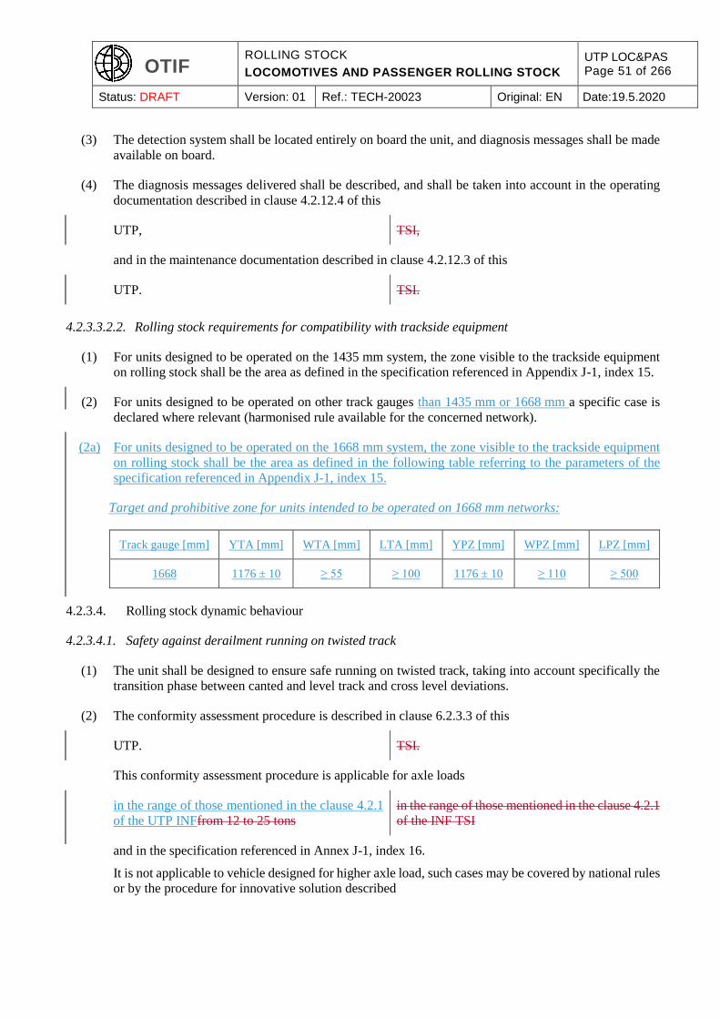
OTIF ROLLING STOCK
LOCOMOTIVES AND PASSENGER ROLLING STOCK
UTP LOC&PAS Page 51 of 266
Status: DRAFT Version: 01 Ref.: TECH-20023 Original: EN Date:19.5.2020
(3) The detection system shall be located entirely on board the unit, and diagnosis messages shall be made
available on board.
(4) The diagnosis messages delivered shall be described, and shall be taken into account in the operating
documentation described in clause 4.2.12.4 of this
UTP, TSI,
and in the maintenance documentation described in clause 4.2.12.3 of this
UTP. TSI.
4.2.3.3.2.2. Rolling stock requirements for compatibility with trackside equipment
(1) For units designed to be operated on the 1435 mm system, the zone visible to the trackside equipment
on rolling stock shall be the area as defined in the specification referenced in Appendix J-1, index 15.
(2) For units designed to be operated on other track gauges than 1435 mm or 1668 mm a specific case is
declared where relevant (harmonised rule available for the concerned network).
(2a) For units designed to be operated on the 1668 mm system, the zone visible to the trackside equipment
on rolling stock shall be the area as defined in the following table referring to the parameters of the
specification referenced in Appendix J-1, index 15.
Target and prohibitive zone for units intended to be operated on 1668 mm networks:
Track gauge [mm] YTA [mm] WTA [mm] LTA [mm] YPZ [mm] WPZ [mm] LPZ [mm]
1668 1176 ± 10 ≥ 55 ≥ 100 1176 ± 10 ≥ 110 ≥ 500
4.2.3.4. Rolling stock dynamic behaviour
4.2.3.4.1. Safety against derailment running on twisted track
(1) The unit shall be designed to ensure safe running on twisted track, taking into account specifically the
transition phase between canted and level track and cross level deviations.
(2) The conformity assessment procedure is described in clause 6.2.3.3 of this
UTP. TSI.
This conformity assessment procedure is applicable for axle loads
in the range of those mentioned in the clause 4.2.1
of the UTP INFfrom 12 to 25 tons
in the range of those mentioned in the clause 4.2.1
of the INF TSI
and in the specification referenced in Annex J-1, index 16.
It is not applicable to vehicle designed for higher axle load, such cases may be covered by national rules
or by the procedure for innovative solution described
OTIF ROLLING STOCK
LOCOMOTIVES AND PASSENGER ROLLING STOCK
UTP LOC&PAS Page 52 of 266
Status: DRAFT Version: 01 Ref.: TECH-20023 Original: EN Date:19.5.2020
in this UTP. in article 10 and Chapter 6 of this TSI.
4.2.3.4.2. Running dynamic behaviour
(1) This clause is applicable to units designed for a speed higher than 60 km/h, except to on-track machines
for which the requirements are set out in Appendix C, clause C.3 and except units designed to be
operated on the 1520 mm track gauge for which the corresponding requirements are considered as “open
point”.
(2) The dynamic behaviour of a vehicle has a strong influence on running safety and track loading. It is an
essential function for safety, covered by the requirements of this clause.
a) Technical requirements
(3) The unit shall run safely and produce an acceptable level of track loading when operated within the
limits defined by the combination(s) of speed and cant deficiency under the reference conditions set out
in the technical documentspecification referenced in Appendix J-21, index 216.
This shall be assessed by verifying that limit values specified below in clauses 4.2.3.4.2.1 and
4.2.3.4.2.2 of this
UTP TSI
are respected; the conformity assessment procedure is described in clause 6.2.3.4 of this
UTP. TSI.
(4) The limit values and conformity assessment mentioned in point (3) are applicable for axle loads in the
range of those mentioned in the clause 4.2.1 of the UTP INF
applicable on the international lines on which the
vehicle is intended to be operated
in the range of those mentioned in the clause 4.2.1
of the INF TSI
and in the specification referenced in Annex J-1, index 16. They are not applicable to vehicles designed
for higher axle load, as harmonised track loading limit values are not defined; such cases may be covered
by national rules or by the procedure for innovative solution described in
this UTP. It shall be the task of the Competent
Authority of each Contracting State to make
available to the applicant the maximum axle load
characteristics of the international lines.
article 10 and Chapter 6 of this TSI.
(5) The running dynamic behaviour test report (including limits of use and track loading parameters) shall
be stated in the technical documentation described in clause 4.2.12 of this
UTP. TSI.
Track loading parameters (including the additional ones Ymax, Bmax and the Bqst where relevant) to be
recorded are defined in the specification referenced in Appendix J-1, index 16 with the modifications
as set out in the technical document referenced in Appendix J-2, index 2.
b) Additional requirements when an active system is used
OTIF ROLLING STOCK
LOCOMOTIVES AND PASSENGER ROLLING STOCK
UTP LOC&PAS Page 53 of 266
Status: DRAFT Version: 01 Ref.: TECH-20023 Original: EN Date:19.5.2020
(6) When active systems (based on software or programmable controller controlling actuators) are used,
the functional failure has typical credible potential to lead directly to “fatalities” for both of the
following scenarios:
1. failure in the active system leading to a non-compliance with limit values for running safety
(defined in accordance with clauses 4.2.3.4.2.1 and 4.2.3.4.2.2).
2. failure in the active system leading to a vehicle outside of the kinematic reference contour of the
carbody and pantograph, due to tilting angle (sway) leading to non-compliance with the values
assumed as set out in clause 4.2.3.1.
Considering this severity of the failure consequence it shall be demonstrated that the risk is controlled
to an acceptable level.
The demonstration of compliance (conformity assessment procedure) is described in clause 6.2.3.5 of
this
UTP. TSI.
c) Additional requirements when an instability detection system is installed (option)
(7) The instability detection system shall provide information regarding the need to take operative measures
(such as reduction of speed etc.), and it shall be described in the technical documentation. The operative
measures shall be described in the operating documentation set out in clause 4.2.12.4 of this
UTP. TSI.
4.2.3.4.2.1 Limit values for running safety
(1) The limit values for running safety which the unit shall meet are specified in the specification referenced
in Appendix J-1, index 17, and additionally for trains intended to be operated with a cant deficiencies
> 165 mm in the specification referenced in Appendix J-1, index 18, with the modifications as set out
in the technical document referenced in Appendix J-2, index 2.
4.2.3.4.2.2 Track loading limit values
(1) The limit values for track loading which the unit shall meet (when assessing with the normal method)
are specified in the specification referenced in Appendix J-1, index 19 with the modifications as set out
in the technical document referenced in Appendix J-2, index 2.
(2) In case the estimated values exceed the limit values expressed above, the operational conditions for the
rolling stock (e.g. maximum speed, cant deficiency) may be adjusted taking into account track
characteristics (e.g. curve radius, cross section of the rail, sleeper spacing, track maintenance intervals).
4.2.3.4.3 Equivalent conicity
4.2.3.4.3.1 Design values for new wheel profiles
(1) The clause 4.2.3.4.3 is applicable to all units, except for unit designed to be operated on the 1520 mm
or 1600 mm track gauge for which the corresponding requirements are an open point.
(2) A new wheel profile and the distance between active faces of the wheels shall be checked in respect of
target equivalent conicities using the calculation scenarios provided in clause 6.2.3.6 of this
OTIF ROLLING STOCK
LOCOMOTIVES AND PASSENGER ROLLING STOCK
UTP LOC&PAS Page 54 of 266
Status: DRAFT Version: 01 Ref.: TECH-20023 Original: EN Date:19.5.2020
UTP TSI
in order to establish the suitability of the new proposed wheel profile for infrastructure
on which the vehicle is designed to be operated. in accordance with the INF TSI.
(3) Units equipped with independently rotating wheels are exempt from these requirements.
4.2.3.4.3.2 In-service values of wheelset equivalent conicity
(1) The combined equivalent conicities the vehicle is designed for, as verified by the demonstration of
conformity of the running dynamic behaviour specified in clause 6.2.3.4 of this
UTP, TSI,
shall be specified for in-service conditions in the maintenance documentation as set out in point
4.2.12.3.2, taking into account the contributions of wheel and rail profiles.
(2) If ride instability is reported, the railway undertaking and the Infrastructure Manager shall localise the
section of the line in a joint investigation.
(3) The railway undertaking shall measure the wheel profiles and the front-to-front distance (distance of
active faces) of the wheelsets in question. The equivalent conicity shall be calculated using the
calculation scenarios provided in clause 6.2.3.6 in order to check if compliance with the maximum
equivalent conicity the vehicle was designed and tested for is met. If it is not the case, the wheel profiles
have to be corrected.
(4) If the wheelset conicity complies with the maximum equivalent conicity the vehicle was designed and
tested for, a joint investigation by the railway undertaking and the infrastructure manager shall be
undertaken to determine the characteristics reason for the instability.
(5) Units equipped with independently rotating wheels are exempt from these requirements.
4.2.3.5. Running gear
4.2.3.5.1. Structural design of bogie frame
(1) For units which include a bogie frame, the integrity of the structure of the bogie frame, axle box housing
and all attached equipment shall be demonstrated based on methods as set out in the specification
referenced in Appendix J-1, index 20.
(2) The body to bogie connection shall comply with the requirements of the specification referenced in
Appendix J-1, index 21.
(3) The hypothesis taken to evaluate the loads due to bogie running (formulas and coefficients) in line with
the specification referenced in Appendix J-1, index 20 shall be justified and documented in the technical
documentation described in clause 4.2.12 of this
UTP. TSI.
OTIF ROLLING STOCK
LOCOMOTIVES AND PASSENGER ROLLING STOCK
UTP LOC&PAS Page 55 of 266
Status: DRAFT Version: 01 Ref.: TECH-20023 Original: EN Date:19.5.2020
4.2.3.5.2. Wheelsets
(1) For the purpose of this
UTP, TSI,
wheelsets are defined to include main parts ensuring the mechanical interface with the track (wheels
and connecting elements: e.g. transverse axle, independent wheel axle) and accessories parts (axle
bearings, axle boxes, gearboxes and brake discs).
(2) The wheelset shall be designed and manufactured with a consistent methodology using a set of load
cases consistent with load conditions defined in clause 4.2.2.10 of this
UTP. TSI.
4.2.3.5.2.1.Mechanical and geometric characteristics of wheelsets
Mechanical behaviour of wheelsets
(1) The mechanical characteristics of the wheelsets shall ensure the safe movement of rolling stock.
The mechanical characteristics cover:
assembly
mechanical resistance and fatigue characteristics
The conformity assessment procedure is described in clause 6.2.3.7 of this
UTP. TSI.
Mechanical behaviour of axles
(2) The characteristics of the axle shall ensure the transmission of forces and torque.
The conformity assessment procedure is described in clause 6.2.3.7 of this
UTP. TSI.
Case of units equipped with independently rotating wheels
(3) The characteristics of the end of axle (interface between wheel and running gear) shall ensure the
transmission of forces and torque.
The conformity assessment procedure shall be in accordance with point (7) of clause 6.2.3.7 of this
UTP. TSI.
Mechanical behaviour of the axle boxes
(4) The axle box shall be designed with consideration of mechanical resistance and fatigue characteristics.
The conformity assessment procedure is described in clause 6.2.3.7 of this
UTP. TSI.
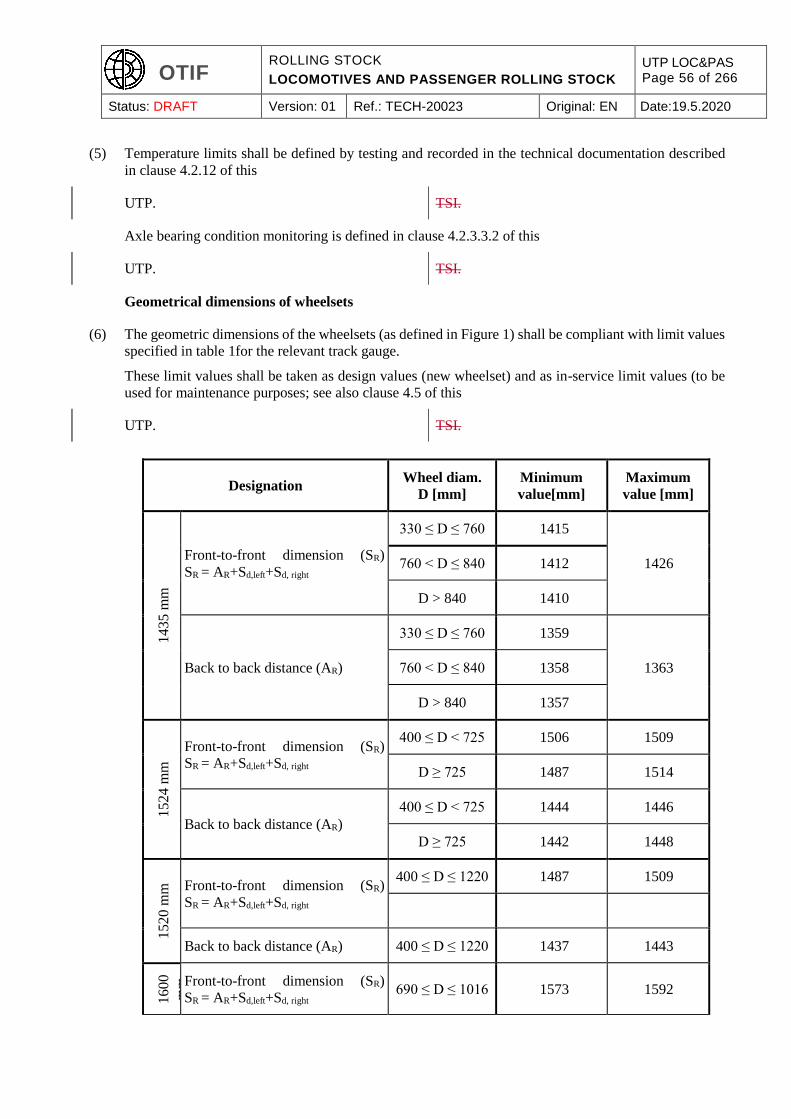
OTIF ROLLING STOCK
LOCOMOTIVES AND PASSENGER ROLLING STOCK
UTP LOC&PAS Page 56 of 266
Status: DRAFT Version: 01 Ref.: TECH-20023 Original: EN Date:19.5.2020
(5) Temperature limits shall be defined by testing and recorded in the technical documentation described
in clause 4.2.12 of this
UTP. TSI.
Axle bearing condition monitoring is defined in clause 4.2.3.3.2 of this
UTP. TSI.
Geometrical dimensions of wheelsets
(6) The geometric dimensions of the wheelsets (as defined in Figure 1) shall be compliant with limit values
specified in table 1for the relevant track gauge.
These limit values shall be taken as design values (new wheelset) and as in-service limit values (to be
used for maintenance purposes; see also clause 4.5 of this
UTP. TSI.
Designation Wheel diam.
D [mm]
Minimum
value[mm]
Maximum
value [mm]
1435 m
m
Front-to-front dimension (SR)
SR = AR+Sd,left+Sd, right
330 ≤ D ≤ 760 1415
1426 760 < D ≤ 840 1412
D > 840 1410
Back to back distance (AR)
330 ≤ D ≤ 760 1359
1363 760 < D ≤ 840 1358
D > 840 1357
15
24
mm
Front-to-front dimension (SR)
SR = AR+Sd,left+Sd, right
400 ≤ D < 725 1506 1509
D ≥ 725 1487 1514
Back to back distance (AR)
400 ≤ D < 725 1444 1446
D ≥ 725 1442 1448
15
20
mm
Front-to-front dimension (SR)
SR = AR+Sd,left+Sd, right
400 ≤ D ≤ 1220 1487 1509
Back to back distance (AR) 400 ≤ D ≤ 1220 1437 1443
1600
mm
Front-to-front dimension (SR)
SR = AR+Sd,left+Sd, right 690 ≤ D ≤ 1016 1573 1592
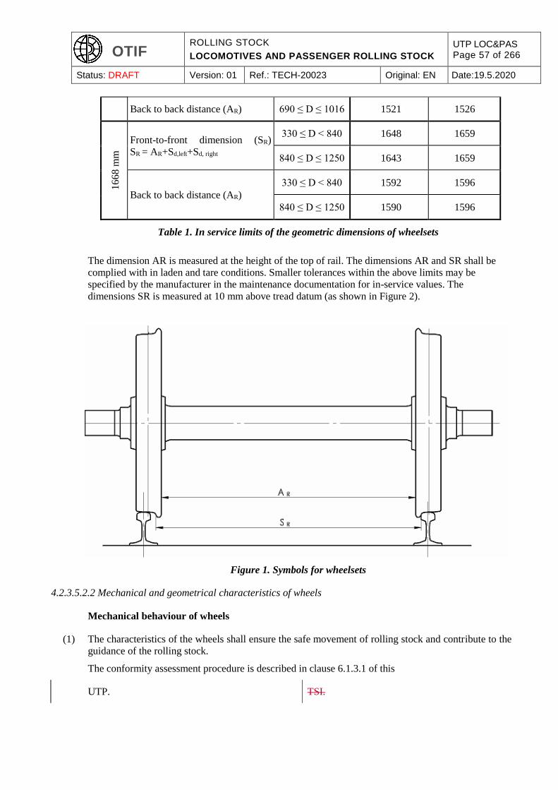
OTIF ROLLING STOCK
LOCOMOTIVES AND PASSENGER ROLLING STOCK
UTP LOC&PAS Page 57 of 266
Status: DRAFT Version: 01 Ref.: TECH-20023 Original: EN Date:19.5.2020
Back to back distance (AR) 690 ≤ D ≤ 1016 1521 1526 1
66
8 m
m
Front-to-front dimension (SR)
SR = AR+Sd,left+Sd, right
330 ≤ D < 840 1648 1659
840 ≤ D ≤ 1250 1643 1659
Back to back distance (AR)
330 ≤ D < 840 1592 1596
840 ≤ D ≤ 1250 1590 1596
Table 1. In service limits of the geometric dimensions of wheelsets
The dimension AR is measured at the height of the top of rail. The dimensions AR and SR shall be
complied with in laden and tare conditions. Smaller tolerances within the above limits may be
specified by the manufacturer in the maintenance documentation for in-service values. The
dimensions SR is measured at 10 mm above tread datum (as shown in Figure 2).
Figure 1. Symbols for wheelsets
4.2.3.5.2.2 Mechanical and geometrical characteristics of wheels
Mechanical behaviour of wheels
(1) The characteristics of the wheels shall ensure the safe movement of rolling stock and contribute to the
guidance of the rolling stock.
The conformity assessment procedure is described in clause 6.1.3.1 of this
UTP. TSI.
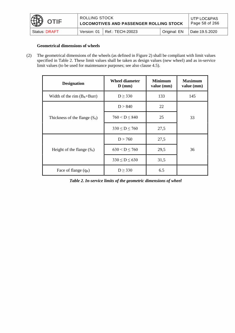
OTIF ROLLING STOCK
LOCOMOTIVES AND PASSENGER ROLLING STOCK
UTP LOC&PAS Page 58 of 266
Status: DRAFT Version: 01 Ref.: TECH-20023 Original: EN Date:19.5.2020
Geometrical dimensions of wheels
(2) The geometrical dimensions of the wheels (as defined in Figure 2) shall be compliant with limit values
specified in Table 2. These limit values shall be taken as design values (new wheel) and as in-service
limit values (to be used for maintenance purposes; see also clause 4.5).
Designation Wheel diameter
D (mm)
Minimum
value (mm)
Maximum
value (mm)
Width of the rim (BR+Burr) D ≥ 330 133 145
Thickness of the flange (Sd)
D > 840 22
33 760 < D ≤ 840 25
330 ≤ D ≤ 760 27,5
Height of the flange (Sh)
D > 760 27,5
36 630 < D ≤ 760 29,5
330 ≤ D ≤ 630 31,5
Face of flange (qR) D ≥ 330 6.5
Table 2. In-service limits of the geometric dimensions of wheel
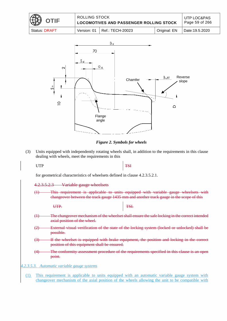
OTIF ROLLING STOCK
LOCOMOTIVES AND PASSENGER ROLLING STOCK
UTP LOC&PAS Page 59 of 266
Status: DRAFT Version: 01 Ref.: TECH-20023 Original: EN Date:19.5.2020
Figure 2. Symbols for wheels
(3) Units equipped with independently rotating wheels shall, in addition to the requirements in this clause
dealing with wheels, meet the requirements in this
UTP TSI
for geometrical characteristics of wheelsets defined in clause 4.2.3.5.2.1.
4.2.3.5.2.3 Variable gauge wheelsets
(1) This requirement is applicable to units equipped with variable gauge wheelsets with
changeover between the track gauge 1435 mm and another track gauge in the scope of this
UTP. TSI.
(1) The changeover mechanism of the wheelset shall ensure the safe locking in the correct intended
axial position of the wheel.
(2) External visual verification of the state of the locking system (locked or unlocked) shall be
possible.
(3) If the wheelset is equipped with brake equipment, the position and locking in the correct
position of this equipment shall be ensured.
(4) The conformity assessment procedure of the requirements specified in this clause is an open
point.
4.2.3.5.3. Automatic variable gauge systems
(1) This requirement is applicable to units equipped with an automatic variable gauge system with
changeover mechanism of the axial position of the wheels allowing the unit to be compatible with
Flange angle
Chamfer Reverse
slope (Taper
OTIF ROLLING STOCK
LOCOMOTIVES AND PASSENGER ROLLING STOCK
UTP LOC&PAS Page 60 of 266
Status: DRAFT Version: 01 Ref.: TECH-20023 Original: EN Date:19.5.2020
1435 mm track gauge and other track gauge(s) within the scope of this UTP by means of passage
through a track gauge changeover facility.
(2) The changeover mechanism shall ensure the locking in the correct intended axial position of the wheel.
(3) After passage through the track gauge changeover facility, the verification of the state of the locking
system (locked or unlocked) and of the position of the wheels shall be performed by one or more of the
following means: visual control, on-board control system or infrastructure/facility control system. In
case of on-board control system, a continuous monitoring shall be possible.
(4) If a running gear is equipped with brake equipment subject to a change in position during the gauge
change operation, the automatic variable gauge system shall ensure the position and safe locking in the
correct position of this equipment simultaneously to those of the wheels.
(5) The failure of the locking of the position of the wheels and braking equipment (if relevant) during
operation has typical credible potential to lead directly to a catastrophic accident (resulting in multiple
fatalities); considering this severity of the failure consequence, it shall be demonstrated that the risk is
controlled to an acceptable level.
(6) The automatic variable gauge system is defined as an IC (clause 5.3.4a). The conformity assessment
procedure is specified in clause 6.1.3.1a (IC level), in clause 6.2.3.5 (safety requirement) and in clause
6.2.3.7a (subsystem level) of this UTP.
(7) The track gauges the unit is compatible with shall be recorded in the technical documentation. A
description of the changeover operation in normal mode, including the type(s) of track gauge
changeover facility(ies) the unit is compatible with, shall be part of the technical documentation (see
also clause 4.2.12.4 (1) of this UTP).
(8) The requirements and conformity assessments required in other sections of this UTP apply
independently for each wheel position corresponding to one track gauge, and have to be documented
accordingly.
4.2.3.6. Minimum curve radius
(1) The minimum curve radius to be negotiated shall be 150 m for all units.
4.2.3.7. Life guards
(1) This requirement applies to units fitted with a driving cab.
(2) The wheels shall be protected against damages caused by minor items on the rails. This requirement
can be met by life guards in front of the wheels of the leading axle.
(3) The height of the lower end of the life guard above the plain rail shall be:
30 mm minimum in all conditions
130 mm maximum in all conditions
taking into account in particular wheel wear and suspension compression.
OTIF ROLLING STOCK
LOCOMOTIVES AND PASSENGER ROLLING STOCK
UTP LOC&PAS Page 61 of 266
Status: DRAFT Version: 01 Ref.: TECH-20023 Original: EN Date:19.5.2020
(4) If an obstacle deflector specified in clause 4.2.2.5 has its lower edge at less than 130 mm above the
plain rail in all conditions, it fulfils the functional requirement of the life guards and therefore it is
permissible not to fit life guards.
(5) A life guard shall be designed to withstand a minimum longitudinal static force without permanent
deformation of 20 kN. This requirement shall be verified by a calculation.
(6) A life guard shall be designed so that, during plastic deformation, it does not foul the track or running
gear and that contact with the wheel tread, if it occurs, does not pose a risk of derailment.
4.2.4. Braking
4.2.4.1. General
(1) The purpose of the train braking system is to ensure that the train’s speed can be reduced or maintained
on a slope, or that the train can be stopped within the maximum allowable braking distance. Braking
also ensures the immobilisation of a train.
(2) The primary factors that influence the braking performance are the braking power (braking force
production), the train mass, the train rolling resistance, the speed, the available adhesion.
(3) Individual unit performance for units operated in various train formations is defined so that the overall
braking performance of the train can be derived.
(4) The braking performance is determined by deceleration profiles [deceleration = F (speed) and
equivalent response time].
Stopping distance, brake weight percentage (also called “lambda” or “braked mass percentage”), braked
mass may also be used, and can be derived (directly or via stopping distance) from deceleration profiles
by a calculation.
The braking performance could vary with the mass of the train or vehicle.
(5) The minimum train braking performance required to operate a train on a line at an intended speed is
dependent on the line characteristics (signalling system, maximum speed, gradients, line safety margin)
and is a characteristic of the infrastructure.
The train or vehicle main data characterising the braking performance is defined in the clause 4.2.4.5
of this
UTP. TSI.
4.2.4.2. Main functional and safety requirements
4.2.4.2.1. Functional requirements
The following requirements apply to all units.
Units shall be equipped with:
(1) a main brake function used during operation for service and emergency braking.

OTIF ROLLING STOCK
LOCOMOTIVES AND PASSENGER ROLLING STOCK
UTP LOC&PAS Page 62 of 266
Status: DRAFT Version: 01 Ref.: TECH-20023 Original: EN Date:19.5.2020
(2) a parking brake function used when the train is parked, allowing the application of a brake force without
any available energy on board for an unlimited period of time.
The main brake function of a train shall be:
(3) continuous: the brake application signal is transmitted from a central command to the whole train by a
control line.
(4) automatic: an inadvertent disruption (loss of integrity, line de-energized…) of the control line leads to
brake activation on all vehicles of the train.
(5) It is permitted to complement the main brake function by additional brake systems described in clause
4.2.4.7 (dynamic brake – braking system linked to traction system) and/or clause 4.2.4.8 (braking
system independent of adhesion conditions).
(6) The dissipation of the braking energy shall be considered in the design of the braking system, and shall
not cause any damage to the components of the braking system in normal operation conditions; this
shall be verified by a calculation as specified in clause 4.2.4.5.4 of this
UTP. TSI.
The temperature reached around the brake components shall also be considered in the design of the
rolling stock.
(7) The design of the brake system shall include means for monitoring and tests as specified in clause
4.2.4.9 of this
UTP. TSI.
The requirements below in this clause 4.2.4.2.1 apply at train level to units for which the operating
formation(s) is (are) defined at design stage [i.e. unit assessed in fixed formation, unit assessed in
predefined formation(s), locomotive operated alone].
(8) The braking performance shall be consistent with safety requirements expressed in clause 4.2.4.2.2 in
case of inadvertent disruption of the brake control line, and in the event of the braking energy supply
being disrupted, the power supply failing or other energy source failure.
(9) In particular, there shall be sufficient braking energy available on board the train (stored energy),
distributed along the train consistent with the design of the brake system, to ensure the application of
the required brake forces.
(10) Successive applications and releases of the brake shall be considered in the design of the braking system
(inexhaustibility).
(11) In case of unintentional train separation, the two parts of the train shall be brought to a standstill; the
braking performances on the two parts of the train are not required to be identical to the braking
performance in normal mode.
(12) In the event of the braking energy supply being disrupted or the power supply failing, it shall be possible
to hold in a stationary position a unit with maximum braking load (as defined in clause 4.2.4.5.2) on a
40 ‰ gradient by using the friction brake of the main brake system alone, for at least two hours.
OTIF ROLLING STOCK
LOCOMOTIVES AND PASSENGER ROLLING STOCK
UTP LOC&PAS Page 63 of 266
Status: DRAFT Version: 01 Ref.: TECH-20023 Original: EN Date:19.5.2020
(13) The unit braking control system shall have three control modes:
emergency braking: application of a predefined brake force in a predefined maximum response
time in order to stop the train with a defined level of brake performance.
service braking: application of an adjustable brake force in order to control the speed of the train,
including stop and temporary immobilisation.
parking braking: application of a brake force to maintain the train (or the vehicle) in permanent
immobilisation in a stationary position, without any available energy on board.
(14) A brake application command, whatever its control mode, shall take control of the brake system, even
in case of active brake release command; this requirement is permitted not to apply when intentional
suppression of the brake application command is given by the driver (e.g. passenger alarm override,
uncoupling...).
(15) For speeds higher than 5 km/h, the maximum jerk due to the use of brakes shall be lower than 4 m/s3.
The jerk behaviour may be derived from the calculation and from the evaluation of the deceleration
behaviour as measured during the brake tests (as described in the clauses 6.2.3.8 and 6.2.3.9).
4.2.4.2.2. Safety requirements
(1) The braking system is the means to stop a train, and therefore contributes to the safety level of the
railway system.
The functional requirements expressed in clause 4.2.4.2.1 contribute to ensure safe functioning of the
braking system; nevertheless, a risk based analysis is necessary to evaluate the braking performance, as
many components are involved.
(2) For the hazardous scenarios considered, the corresponding safety requirements shall be met, as defined
in the table 3 below.
Where a severity is specified within this table, it shall be demonstrated that the corresponding risk is
controlled to an acceptable level, considering the functional failure with their typical credible potential
to lead directly to that severity as defined within the table.
Safety requirement to be met
Functional failure with its
hazardous scenario
Associated
severity/Consequen
ce to be prevented
Minimum allowable
number of combinations
of failures
No.1
Applies to units fitted with a cab (brake command)
After activation of an emergency
brake command no deceleration
of the train due to failure in the
brake system (complete and
permanent loss of the brake
force).
Fatalities 2 (no single failure is
accepted)
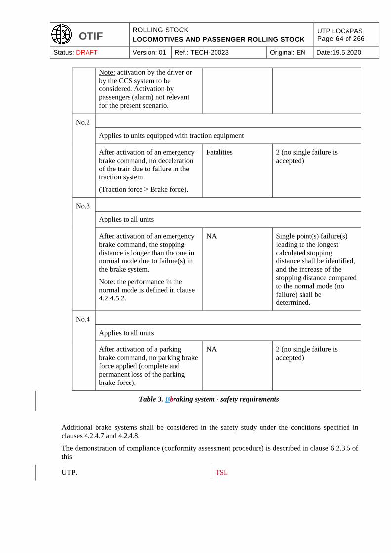
OTIF ROLLING STOCK
LOCOMOTIVES AND PASSENGER ROLLING STOCK
UTP LOC&PAS Page 64 of 266
Status: DRAFT Version: 01 Ref.: TECH-20023 Original: EN Date:19.5.2020
Note: activation by the driver or
by the CCS system to be
considered. Activation by
passengers (alarm) not relevant
for the present scenario.
No.2
Applies to units equipped with traction equipment
After activation of an emergency
brake command, no deceleration
of the train due to failure in the
traction system
(Traction force ≥ Brake force).
Fatalities 2 (no single failure is
accepted)
No.3
Applies to all units
After activation of an emergency
brake command, the stopping
distance is longer than the one in
normal mode due to failure(s) in
the brake system.
Note: the performance in the
normal mode is defined in clause
4.2.4.5.2.
NA Single point(s) failure(s)
leading to the longest
calculated stopping
distance shall be identified,
and the increase of the
stopping distance compared
to the normal mode (no
failure) shall be
determined.
No.4
Applies to all units
After activation of a parking
brake command, no parking brake
force applied (complete and
permanent loss of the parking
brake force).
NA 2 (no single failure is
accepted)
Table 3. Bbraking system - safety requirements
Additional brake systems shall be considered in the safety study under the conditions specified in
clauses 4.2.4.7 and 4.2.4.8.
The demonstration of compliance (conformity assessment procedure) is described in clause 6.2.3.5 of
this
UTP. TSI.
OTIF ROLLING STOCK
LOCOMOTIVES AND PASSENGER ROLLING STOCK
UTP LOC&PAS Page 65 of 266
Status: DRAFT Version: 01 Ref.: TECH-20023 Original: EN Date:19.5.2020
4.2.4.3. Type of brake system
(1) Units designed and assessed to be operated in general operation (various formations of vehicles from
different origins; train formation not defined at design stage) on other track gauge systems than the
1520 mm system shall be fitted with a brake system with a brake pipe compatible with the UIC brake
system. To this end, the specification referenced in Appendix J-1, index 22. "Requirements for the brake
system of trains hauled by a locomotive" specifies the principles to be applied.
This requirement is set to ensure technical compatibility of the brake function between vehicles of
various origins in a train.
(2) There is no requirement on the type of brake system for units (trainsets or vehicles) assessed in fixed or
predefined formation.
4.2.4.4. Brake command
4.2.4.4.1. Emergency braking command
(1) This clause applies to units fitted with a driver’s cab.
(2) At least two independent emergency brake command devices shall be available, allowing the activation
of the emergency brake by a simple and single action from the driver in his normal driving position,
using one hand.
The sequential activation of these two devices may be considered in the demonstration of compliance
to the safety requirement N°1 of table 3 of clause 4.2.4.2.2.
One of these devices shall be a red punch button (mushroom push button).
The emergency brake position of these two devices when activated shall be self locking by a mechanical
device; unlocking this position shall be possible only by an intentional action.
(3) The activation of the emergency brake shall also be possible by the Control-Command and signalling
on-board system
. , as defined in the CCS TSI.
(4) Unless the command is cancelled, the emergency brake activation shall lead permanently, automatically
to the following actions:
transmission of an emergency brake command along the train by the brake control line.
cut-off of all tractive effort in less than 2 seconds; this cut-off shall not be able to be reset until
the traction command is cancelled by the driver.
an inhibition of all “release brake” commands or actions.
4.2.4.4.2 Service braking command
(1) This clause applies to units fitted with a driver’s cab.
(2) The service brake function shall allow the driver to adjust (by application or release) the brake force
between a minimum and a maximum value in a range of at least 7 steps (including brake release and
maximum brake force), in order to control the speed of the train.
OTIF ROLLING STOCK
LOCOMOTIVES AND PASSENGER ROLLING STOCK
UTP LOC&PAS Page 66 of 266
Status: DRAFT Version: 01 Ref.: TECH-20023 Original: EN Date:19.5.2020
(3) The service braking command shall be active only in one location in a train. To meet this requirement,
it shall be possible to isolate the service braking function of the other service braking command(s) of
the unit(s) part of a train formation, as defined for fixed and predefined formations.
(4) When the speed of the train is higher than 15 km/h, the service brake activation by the driver shall lead
automatically to the cut-off of all tractive effort; this cut-off shall not be reset until the traction command
is cancelled by the driver.
Notes:
in case of service brake and traction controlled by automatic speed regulation, the traction cut-
off is not required to be cancelled by the driver.
a friction brake may be used intentionally at speed higher than 15 km/h with traction for specific
purpose (de-icing, cleaning of brake components...); it shall not be possible to use these particular
functionalities in case of emergency or service brake activation.
4.2.4.4.3 Direct braking command
(1) Locomotives (units designed to haul freight wagons or passenger carriages) assessed for general
operation shall be fitted with a direct brake system.
(2) The direct brake system shall allow the application of a brake force on the concerned unit(s)
independently of the main brake command, with other unit(s) of the train remaining without brake
applied.
4.2.4.4.4 Dynamic braking command
If a unit is equipped with a dynamic brake system:
(1) It shall be possible to prevent the use of regenerative braking on electric units so that there is no return
of energy to the overhead contact line when driving on a line which does not allow that.
See also clause 4.2.8.2.3 for regenerative brake.
(2) It is permitted to use a dynamic brake independently from other brake systems, or together with other
brake systems (blending).
(3) Where on locomotives the dynamic brake is used independently from other brake systems, it shall be
possible to limit the maximum value and rate of variation of the dynamic brake effort to predefined
values.
Note: this limitation relates to the forces transmitted to the track when locomotive(s) is (are) integrated
in a train; it may be applied at operating level by setting the values necessary for compatibility with a
particular line (e.g. line with high gradient and low curve radius).
4.2.4.4.5 Parking braking command
(1) This clause applies to all units.
(2) The parking braking command shall lead to the application of a defined brake force for an unlimited
period of time, during which a lack of any energy on board may occur.
OTIF ROLLING STOCK
LOCOMOTIVES AND PASSENGER ROLLING STOCK
UTP LOC&PAS Page 67 of 266
Status: DRAFT Version: 01 Ref.: TECH-20023 Original: EN Date:19.5.2020
(3) It shall be possible to release the parking brake at standstill, including for rescue purposes.
(4) For units assessed in fixed or pre-defined formations, and for locomotives assessed for general
operation, the parking brake command shall be activated automatically when the unit is switched off.
For other units, the parking brake command shall be either activated manually, or activated
automatically when the unit is switched off.
Note: the application of the parking brake force may depend on the status of the main brake function; it
shall be effective when the energy on board to apply the main brake function is lost or is going to
increase or decrease (after having switched on or off the unit).
4.2.4.5. Braking performance
4.2.4.5.1 General requirements
(1) The unit (trainset or vehicle) braking performance [deceleration = F (speed) and equivalent response
time] shall be determined by calculation as defined in the specification referenced in Appendix J-1,
index 23, considering a level track.
Each calculation shall be performed for wheel diameters corresponding to new, half-worn and worn
wheels, and shall include the calculation of the required wheel/rail adhesion level (see clause 4.2.4.6.1).
(2) The friction coefficients used by friction brake equipment and considered in the calculation shall be
justified (see the specification referenced in Appendix J-1, index 24).
(3) The braking performance calculation shall be performed for the two control modes: emergency brake
and maximum service brake.
(4) The braking performance calculation shall be performed at design stage, and shall be revised (correction
of parameters) after the physical tests required in the clauses 6.2.3.8 and 6.2.3.9, in order to be consistent
with test results.
The final braking performance calculation (consistent with test results) shall be part of the technical
documentation specified in clause 4.2.12.
(5) The maximum average deceleration developed with all brakes in use, including the brake independent
of wheel/rail adhesion, shall be lower than 2.5 m/s²; this requirement is linked to the longitudinal
resistance of the track.
4.2.4.5.2 Emergency braking
Response time:
(1) For units assessed in fixed formation(s) or pre-defined formation(s), the equivalent response time (*)
and the delay time (*) evaluated on the total emergency braking force developed in case of the
emergency brake command shall be lower than the following values:
Equivalent response time:
3 seconds for units of maximum design speed higher or equal to 250 km/h
5 seconds for other units
Delay time: 2 seconds

OTIF ROLLING STOCK
LOCOMOTIVES AND PASSENGER ROLLING STOCK
UTP LOC&PAS Page 68 of 266
Status: DRAFT Version: 01 Ref.: TECH-20023 Original: EN Date:19.5.2020
(2) For units designed and assessed for general operation, the response time shall be as specified for the
UIC brake system (see also clause 4.2.4.3: the brake system shall be compatible with the UIC brake
system).
(*): to be evaluated on the total brake force, or on pressure in brake cylinders in case of pneumatic brake
system; definition according to the specification referenced in Appendix J-1, index 25, clause 5.3.3.
Calculation of the deceleration:
(3) For all units, the emergency braking performance calculation shall be performed in accordance with the
specification referenced in Appendix J-1, index 26; the deceleration profile and stopping distances at
the following initial speeds (if lower than the maximum design speed of the unit) shall be determined:
30 km/h; 100 km/h; 120 km/h; 140 km/h; 160 km/h; 200 km/h; 230 km/h; 300 km/h; maximum design
speed of the unit.
(4) For units designed and assessed for general operation, the brake weight percentage (lambda) shall also
be determined.
The specification referenced in Appendix J-1, index 25, clause 5.12 specifies how other parameters
[brake weight percentage (lambda), braked mass] can be derived from the calculation of the deceleration
or from the stopping distance of the unit.
(5) The emergency braking performance calculation shall be performed with a brake system in two different
modes, and considering degraded conditions:
Normal mode: no failure in the brake system and nominal value of the friction coefficients
(corresponding to dry conditions) used by friction brake equipment. This calculation provides
the braking performance normal mode.
Degraded mode: corresponding to the failures considered in clause 4.2.4.2.2, hazard no. 3, and
nominal value of the friction coefficients used by friction brake equipment. Degraded mode shall
consider possible single failures; to that end, the emergency braking performance shall be
determined for the case of single point(s) failure(s) leading to the longest stopping distance, and
the associated single failure shall be clearly identified (component involved and failure mode,
failure rate if available).
Degraded conditions: in addition, the emergency braking performance calculation shall be
performed with reduced values of the friction coefficient, with consideration of limit values for
temperature and humidity (see the specification referenced in Appendix J-1, index 27, clause
5.3.1.4).
Note: these different modes and conditions have to be considered particularly when advanced Control
Command and Signalling systems (such as ETCS) are implemented, aiming at optimising the railway
system.
(6) The emergency braking performance calculation shall be performed for the three following load
conditions:
minimum load: “design mass in working order” (as described in clause 4.2.2.10)
normal load: “design mass under normal payload” (as described in clause 4.2.2.10)
maximum braking load: load condition lower or equal to “design mass under exceptional
payload” (as described in clause 4.2.2.10).
OTIF ROLLING STOCK
LOCOMOTIVES AND PASSENGER ROLLING STOCK
UTP LOC&PAS Page 69 of 266
Status: DRAFT Version: 01 Ref.: TECH-20023 Original: EN Date:19.5.2020
In case this load condition is lower than “design mass under exceptional payload, it shall be justified
and documented in the general documentation described in clause 4.2.12.2.
(7) Tests shall be performed to validate the emergency braking calculation, according to the conformity
assessment procedure specified in clause 6.2.3.8.
(8) For each load condition, the lowest result (i.e. leading to longest stopping distance) of the "emergency
braking performance in normal mode" calculations at the design maximum speed (revised according to
the results of tests required above) shall be recorded in the technical documentation defined in clause
4.2.12.2 of this
UTP. TSI.
(9) Additionally, for units assessed in fixed or predefined formation of design maximum speed higher than
or equal to 250 km/h, the stopping distance in case of "emergency braking performance in normal
mode" shall not exceed the following values for the load condition “normal load”:
5360 m from the speed of 350 km/h (if ≤ design maximum speed).
3650 m from the speed 300 km/h (if ≤ design maximum speed).
2430 m from the speed 250 km/h.
1500 m from the speed 200 km/h.
4.2.4.5.3. Service braking
Calculation of the deceleration:
(1) For all units, the maximum service braking performance calculation shall be performed in accordance
with the specification referenced in Appendix J-1, index 28 with a brake system in normal mode, with
nominal value of the friction coefficients used by friction brake equipment for the load condition
“design mass under normal payload” at the design maximum speed.
(2) Tests shall be performed to validate the maximum service braking calculation, according to the
conformity assessment procedure specified in clause 6.2.3.9.
Maximum service braking performance:
(3) When the service braking has higher design performance capability than the emergency braking, it shall
be possible to limit the maximum service braking performance (by design of the braking control system,
or as a maintenance activity) at a level lower than the emergency braking performance.
Note:
a Contracting State a Member State
may ask the emergency braking performance to be at a higher level than the maximum service braking
performance for safety reasons, but in any case it cannot prevent the access to a railway undertaking
using a higher maximum service braking performance, unless that
a Contracting State a Member State
is able to demonstrate that the national safety level is endangered.

OTIF ROLLING STOCK
LOCOMOTIVES AND PASSENGER ROLLING STOCK
UTP LOC&PAS Page 70 of 266
Status: DRAFT Version: 01 Ref.: TECH-20023 Original: EN Date:19.5.2020
4.2.4.5.4 Calculations related to thermal capacity
(1) This clause applies to all units.
(2) For OTMs, it is allowed to verify this requirement by temperature measurements on wheels and brake
equipment.
(3) The brake energy capacity shall be verified by calculation showing that the braking system in normal
mode is designed to withstand the dissipation of the braking energy. The reference values used in this
calculation for the components of the braking system that dissipate energy shall either be validated by
a thermal test or by previous experience.
This calculation shall include the scenario consisting of 2 successive emergency brake applications from
the maximum speed (time interval corresponding to the time needed to accelerate the train up to the
maximum speed) on level track for the load condition “maximum braking load”.
In case of unit that cannot be operated alone as a train, the time interval between 2 successive emergency
brake applications used in the calculation shall be reported.
(4) The maximum line gradient, associated length and operating speed for which the brake system is
designed in relation with brake thermal energy capacity shall also be defined by a calculation for the
load condition “maximum braking load”, with the service brake being used to maintain the train at a
constant operating speed.
The result (maximum line gradient, associated length and operating speed) shall be recorded in the
rolling stock documentation defined in clause 4.2.12 of this
UTP. TSI.
The following “reference case” for the slope to be considered is suggested: maintain the speed of
80 km/h on a slope of 21 ‰ constant gradient over a distance of 46 km. If this reference case is used,
the documentation may only mention the compliance to it.
(5) For units assessed in fixed and predefined formation of design maximum speed higher than or equal to
250 km/h, they shall additionally be designed to operate with braking system in normal mode and load
condition “maximum braking load” at speed equal to 90 % of the maximum operating speed on
maximum descending gradient of 25 ‰ during 10 km, and on maximum descending gradient of 35 ‰
during 6 km.
4.2.4.5.5 Parking brake
Performance:
(1) A unit (train or vehicle) in load condition “design mass in working order” without any power supply
available, and stationary permanently on a 40 ‰ gradient, shall be kept immobilised.
(2) Immobilisation shall be achieved by means of the parking brake function, and additional means (e.g.
scotches) in case where the parking brake is unable to achieve the performance on its own; the required
additional means shall be available on board the train.
Calculation:
OTIF ROLLING STOCK
LOCOMOTIVES AND PASSENGER ROLLING STOCK
UTP LOC&PAS Page 71 of 266
Status: DRAFT Version: 01 Ref.: TECH-20023 Original: EN Date:19.5.2020
(3) The unit (train or vehicle) parking brake performance shall be calculated as defined in the specification
referenced in Appendix J-1, index 29. The result (gradient where the unit is kept immobilized by the
parking brake alone) shall be recorded in the technical documentation defined in clause 4.2.12 of this
UTP. TSI.
4.2.4.6. Wheel rail adhesion profile - Wheel slide protection system
4.2.4.6.1 Limit of wheel rail adhesion profile
(1) The braking system of a unit shall be designed so that emergency brake performance (dynamic brake
included if it contributes to the performance) and the service brake performance (without dynamic
brake) do not assume a calculated wheel/rail adhesion for each wheelset in the speed range > 30 km/h
and < 250 km/h higher than 0.15 with the following exceptions:
for units assessed in fixed or pre-defined formation(s) having 7 axles or less, the calculated
wheel/rail adhesion shall not be higher than 0.13.
for units assessed in fixed or pre-defined formation(s) having 20 axles or more the calculated
wheel/rail adhesion for the load case “minimum load” is permitted to be higher than 0.15, but
shall not be higher than 0.17.
Note: for the load case “normal load”, there is no exception; the limit value of 0.15 applies.
This minimum number of axles may be reduced to 16 axles if the test required in section 4.2.4.6.2
related to the efficiency of the WSP system is performed for the load case “minimum load”, and
provides positive result.
In the speed range > 250 km/h and ≤ 350 km/h, the three limit values above shall decline linearly in
order to be reduced by 0.05 at 350 km/h.
(2) The above requirement shall also apply for a direct brake command described in clause 4.2.4.4.3.
(3) The design of a unit shall not assume wheel/rail adhesion higher than 0.12 when calculating the parking
brake performance.
(4) These limits of wheel rail adhesion shall be verified by calculation with the smallest wheel diameter,
and with the 3 load conditions considered in clause 4.2.4.5.2.
All values of adhesion shall be rounded to two decimal places.
4.2.4.6.2. Wheel slide protection system (WSP)
(1) A wheel slide protection system (WSP) is a system designed to make the best use of available adhesion
by a controlled reduction and restoration of the brake force to prevent wheelsets from locking and
uncontrolled sliding, thereby minimising the extension of stopping distances and possible wheel
damage.
Requirements on the presence and use of a WSP system on the unit:
(2) Units designed for maximum service speed higher than 150 km/h shall be fitted with a WSP system.
OTIF ROLLING STOCK
LOCOMOTIVES AND PASSENGER ROLLING STOCK
UTP LOC&PAS Page 72 of 266
Status: DRAFT Version: 01 Ref.: TECH-20023 Original: EN Date:19.5.2020
(3) Units equipped with brake blocks on wheel running surface with a brake performance which assumes
in the speed range > 30 km/h a calculated wheel/rail adhesion higher than 0.12 shall be fitted with a
WSP system.
Units not equipped with brake blocks on wheel running surface with a brake performance which
assumes in the speed range > 30 km/h a calculated wheel/rail adhesion higher than 0.11 shall be fitted
with a WSP system.
(4) The requirement on the WSP system above shall apply to the two brake modes: emergency brake and
service brake.
It shall also apply to the dynamic brake system, which is part of the service brake, and can be part of
the emergency brake (see clause 4.2.4.7).
Requirements on the WSP system performance:
(5) For units equipped with a dynamic braking system, a WSP system (if present according to the point
above) shall control the dynamic brake force; when this WSP system is not available, the dynamic brake
force shall be inhibited, or limited in order not to lead a wheel/rail adhesion demand higher than 0.15.
(6) The wheel slide protection system shall be designed according to the specification referenced in
Appendix J-1, index 30, clause 4, and verified according to the methodology defined in the specification
referenced in Appendix J-1, index 30, clauses 5 and 6; when reference is made to the specification
referenced in Appendix J-1, index 30, clause 6.2 “overview of required test programmes”, only the
clause 6.2.3 applies, and it applies to all types of units.
(7) Requirements on performance at unit level:
If a unit is equipped with a WSP, a test shall be done to verify the efficiency of the WSP system
(maximum extension of the stopping distance compared to stopping distance on dry rail) when
integrated in the unit; the conformity assessment procedure is specified in clause 6.2.3.10.
The relevant components of the wheel slide protection system shall be considered in the safety analysis
of the emergency brake function required in clause 4.2.4.2.2.
(8) Wheel rotation monitoring system (WRM):
Units of design maximum speed higher or equal to 250 km/h shall be equipped with a WRM system to
advise the driver that an axle has seized; the WRM system shall be designed according to the
specification referenced in Appendix J-1, index 30, clause 4.2.4.3.
4.2.4.7. Dynamic brake - Braking system linked to traction system
Where the braking performance of the dynamic brake or of braking system linked to the traction system
is included in the performance of the emergency braking in normal mode defined in clause 4.2.4.5.2,
the dynamic brake or the braking system linked to traction:
(1) Shall be commanded by the main brake system control line (see clause 4.2.4.2.1).
(2) Shall be subject to a safety analysis covering the hazard “after activation of an emergency command,
complete loss of the dynamic brake force”.
This safety analysis shall be considered in the safety analysis required by the safety requirement N°3
set out in clause 4.2.4.2.2 for the emergency brake function.
OTIF ROLLING STOCK
LOCOMOTIVES AND PASSENGER ROLLING STOCK
UTP LOC&PAS Page 73 of 266
Status: DRAFT Version: 01 Ref.: TECH-20023 Original: EN Date:19.5.2020
For electric units, in case the presence on-board the unit of the voltage delivered by the external power
supply is a condition for the dynamic brake application, the safety analysis shall cover failures leading
to absence on-board the unit of that voltage.
In case the hazard above is not controlled at the level of the rolling stock (failure of the external power
supply system), the braking performance of the dynamic brake or of braking system linked to the
traction system shall not be included in the performance of the emergency braking in normal mode
defined in clause 4.2.4.5.2.
4.2.4.8. Braking system independent of adhesion conditions
4.2.4.8.1. General
(1) Brake systems able to develop a brake force applied on the rail, independent of the wheel/rail adhesion
condition, are a means of providing additional braking performance when the requested performance is
higher than the performance corresponding to the limit of the available wheel rail adhesion (see clause
4.2.4.6).
(2) It is permissible to include the contribution of brakes independent of wheel/rail adhesion in the braking
performance in normal mode defined in clause 4.2.4.5 for the emergency brake; in such a case, the brake
system independent of adhesion condition:
(3) Shall be commanded by the main brake system control line (see clause 4.2.4.2.1).
(4) Shall be subject of a safety analysis covering the hazard “after activation of an emergency command,
complete loss of the brake force independent of the wheel/rail adhesion”.
This safety analysis shall be considered in the safety analysis required by the safety requirement N°3
set out in clause 4.2.4.2.2 for the emergency brake function.
4.2.4.8.2 Magnetic track brake
(1) Requirements on magnetic brakes specified for compatibility with train detection system based on axle
counters by the CCS subsystem are referenced in clause point 4.2.3.3.1.2 (10) of this
UTP. TSI.
(2) A magnetic track brake is allowed to be used as an emergency brake,
unless the contrary is specified by a Contracting
State in a National Technical Requirement which
is in force according to APTU Article 12.
as mentioned in the INF TSI, clause 4.2.6.2.2.
(3) The geometrical characteristics of the end elements of the magnet in contact with the rail shall be as
specified for one of the types described in the specification referenced in Appendix J-1, index 31.
(4) Magnetic track brake shall not be used at speed higher than 280 km/h.
(5) The braking performance of the unit specified in clauses 4.2.4.5.2 of this UTP shall be determined with
and without the use of magnetic track brakes.
OTIF ROLLING STOCK
LOCOMOTIVES AND PASSENGER ROLLING STOCK
UTP LOC&PAS Page 74 of 266
Status: DRAFT Version: 01 Ref.: TECH-20023 Original: EN Date:19.5.2020
4.2.4.8.3 Eddy current track brake
(1) This clause covers only eddy current track brake developing a brake force between the rolling stock
unit and the rail.
(2) Requirements on eddy current track brakes specified for compatibility with train detection system based
on axle counters, track circuits, wheel detectors and vehicle detectors based on inductive loops by the
CCS subsystem are referenced in clause point 4.2.3.3.1.2 (10) of this
UTP. TSI.
(3) If the eddy current track brake requires a displacement of its magnets when the brake is applied, the
unobstructed movement of such magnets between the “brake released” and “brake applied” positions
shall be demonstrated by calculation in accordance with the specification referenced in Appendix J-1,
index 14.
(4) The maximum distance between the eddy current track brake and the track corresponding to “brake
released” position will be recorded in the technical documentation described in clause 4.2.12 of this
UTP.
(5) The eddy current track brake shall not operate below a fixed speed threshold.
(6) The conditions for use of eddy current track brake for technical compatibility with the track are not
harmonised (regarding in particular their effect on rail heating and vertical force) Therefore,
requirements to be met by eddy current track brake and are an open point.
(7) The Infrastructure Manager shall provide
information
The Register of Infrastructure indicates per track
section
if their use is allowed, and provides in such case their conditions for use.
The maximum distance between the eddy current track brake and the track corresponding to
“brake released” referred to in point (4),
Fixed speed threshold referred to in point (5),
Vertical force as a function of the train speed, for the case of full application of eddy current
track brake (emergency braking) and limited application of eddy current brake (service braking),
Braking force as a function of the train speed, for the case of full application of eddy current
track brake (emergency braking) and limited application of eddy current brake (service braking).
(8) The braking performance of the unit specified in clauses 4.2.4.5.2 and 4.2.4.5.3 of this UTP shall be
determined with and without the use of eddy current track brakes.
(1) (4) Until the “open point” is closed, the values of maximum longitudinal braking force applied to the
track by the eddy current track brake
are
105 kN for brake applications with
a force less than 2/3 of full service
braking,
specified in the clause 4.2.4.5 of the HS RST
2008 TSI and used at speed ≥ 50 km/h are
deemed to be compatible with HS lines.
OTIF ROLLING STOCK
LOCOMOTIVES AND PASSENGER ROLLING STOCK
UTP LOC&PAS Page 75 of 266
Status: DRAFT Version: 01 Ref.: TECH-20023 Original: EN Date:19.5.2020
Linear between 105 kN and 180 kN
for brake applications between 2/3
and full service braking,
180 kN for full service braking,
360 kN in emergency braking,
considering the worst case and used at
speed ≥ 50 km/h.
These values are deemed to be
compatible with high speed lines.
4.2.4.9. Brake state and fault indication
(1) Information available to train staff shall allow the identification of degraded conditions concerning the
rolling stock (brake performance lower than the performance required), for which specific operating
rules apply. To that end, it shall be possible at certain phases during operation for the train staff to
identify the status (applied or released or isolated) of the main (emergency and service) and parking
brake systems, and the status of each part (including one or several actuators) of these systems that can
be controlled and/or isolated independently.
(2) If the parking brake always depends directly on the state of main brake system, it is not required to have
an additional and specific indication for the parking brake system.
(3) The phases that shall be considered during operation are standstill and running.
(4) When at a standstill, train staff shall be able to check from inside and/or outside of the train:
The continuity of the train brake control command line,
The availability of the braking energy supply along the train,
The status of the main brake and parking brake systems and the status of each part (including
one or several actuators) of these systems that can be controlled and/or isolated separately (as
described above in the first paragraph of this clause), excepted for dynamic brake and braking
system linked to traction systems.
(5) When running, the driver shall be able to check from the driving position in the cab:
The status of the train brake control command line,
The status of the train brake energy supply,
The status of the dynamic brake and braking system linked to traction system where they are
included in the performance of the emergency braking in normal mode,
The status applied or released of at least one part (actuator) of the main brake system which is
controlled independently (e.g. a part which is installed on the vehicle fitted with an active cab).
(6) The function providing the information described above to the train staff is a function essential to safety,
as it is used for the train staff to evaluate the braking performance of the train.
Where local information is provided by indicators, the use of harmonised indicators ensures the required
safety level.
Where a centralised control system allowing the train staff to perform all checks from one location (i.e.
inside the drivers cab) is provided, it shall be subject to a reliability study, considering the failure mode
OTIF ROLLING STOCK
LOCOMOTIVES AND PASSENGER ROLLING STOCK
UTP LOC&PAS Page 76 of 266
Status: DRAFT Version: 01 Ref.: TECH-20023 Original: EN Date:19.5.2020
of components, redundancies, periodic checks and other provisions; based on this study, operating
conditions of the centralised control system shall be defined and provided in the operating
documentation described in clause 4.2.12.4.
(7) Applicability to units intended for general operation:
Only functionalities that are relevant to the design characteristics of the unit (e.g. presence of a cab, ...)
shall be considered.
The signals transmission required (if any) between the unit and the other coupled unit(s) in a train for
the information regarding the brake system to be available at train level shall be documented, taking
into account functional aspects. This
UTP TSI
does not impose any technical solution regarding physical interfaces between units.
4.2.4.10. Brake requirements for rescue purposes
(1) All brakes (emergency, service, parking) shall be fitted with devices allowing their release and isolation.
These devices shall be accessible and functional whether the train or vehicle is: powered, non-powered
or immobilised without any available energy on board.
(2) For units intended to be operated on other track gauge systems than 1520 mm system, it shall be
possible, following a failure during operation, to rescue a train with no energy available on board by a
recovery power unit equipped with a pneumatic brake system compatible with the UIC brake system
(brake pipe as braking control command line).
Note: see clause 4.2.2.2.4 of this
UTP TSI
for mechanical and pneumatical interfaces of the recovery unit.
(3) During the rescue, it shall be possible to have a part of the brake system of the rescued train controlled
by means of an interface device; in order to meet this requirement, it is allowed to rely on low voltage
provided by a battery to supply control circuits on the rescued train.
(4) The braking performance developed by the rescued train in this particular operating mode shall be
evaluated by a calculation, but is not required to be the same as the braking performance described in
clause 4.2.4.5.2. The calculated braking performance and rescue operating conditions shall be part of
the technical documentation described in clause 4.2.12.
(5) This requirement does not apply to units which are operated in a train formation of less than 200 tons
(load condition “design mass in working order”).
4.2.5. Passenger related items
Vehicles in international traffic that are intended to
carry passengers shall meet the requirements as set
out in UTP PRM to cover parameters such as:
For information purposes only, the following non
exhaustive list gives an overview of the basic
parameters covered by the PRM TSI, which are
applicable to units which are intended to carry
passengers:
OTIF ROLLING STOCK
LOCOMOTIVES AND PASSENGER ROLLING STOCK
UTP LOC&PAS Page 77 of 266
Status: DRAFT Version: 01 Ref.: TECH-20023 Original: EN Date:19.5.2020
seats, including priority seats
wheelchair spaces
exterior doors, including dimensions, passenger interface for controls
interior doors, including dimensions, passenger interface for controls
toilets
clearways
lighting
customer Information
floor height changes
handrails
wheelchair accessible sleeping accommodation
step position for vehicle access and egress, including steps and boarding aids.
Additional requirements are specified below in this clause.
4.2.5.1. Sanitary systems
(1) If a water tap is provided in a unit and unless the water is provided from the tap in accordance with
Directive 98/83/EC9,
or according to the regulations in the Contracting
State that prescribe at least equivalent water
conditions as in the above-mentioned Directive,
a visual sign shall clearly indicate that the water provided at the tap is not drinkable.
(2) Sanitary systems (toilets, washrooms, bar/restaurant facilities) where fitted shall not allow the release
of any material that may be detrimental to the health of people or to the environment. Released materials
(i.e. treated water; water with soap directly released from washrooms excluded) shall be conformant to
the applicable European regulations under the Water Framework Directive
, or applicable regulations in the Contracting State
that prescribe at least equivalent or better
conditions for released materials than the European
regulations under the Water Framework Directive
referred to:
The bacterial content of water discharged from sanitary systems shall not at any time exceed the
bacterial content value for Intestinal enterococci and Escherichia coli bacteria specified as ‘good’
for Inland waters in European Directive 2006/7/EC10
9 OJ L 330, 05.12.1998, p.32 10 OJ L 64, 04.03.2006, p.37
OTIF ROLLING STOCK
LOCOMOTIVES AND PASSENGER ROLLING STOCK
UTP LOC&PAS Page 78 of 266
Status: DRAFT Version: 01 Ref.: TECH-20023 Original: EN Date:19.5.2020
, or according to the regulations in the
Contracting State that prescribe a lower or
equivalent content of the above- mentioned
bacteria compared to the above-mentioned
Directive,
concerning the management of bathing water quality.
The treatment processes shall not introduce substances that are identified in Annex I of Directive
2006/11/EC11
, or regulations applicable in the
Contracting States with equivalent content,
on pollution caused by certain dangerous substances discharged into the aquatic environment of
the
Contracting State. Union.
(3) To limit the dispersion of released liquid on the trackside, uncontrolled discharge from any source shall
take place downwards only, under the body frame of the vehicle in a distance not greater than 0,7 metres
from the longitudinal centre line of the vehicle.
(4) The following shall be provided in the technical documentation described in clause 4.2.12:
The presence and type of toilets in a unit,
The characteristics of the flushing medium, if it is not clean water,
The nature of the treatment system for released water and the standards against which conformity
has been assessed.
4.2.5.2. Audible communication system
(1) This clause applies to all units designed to carry passengers and units designed to haul passenger trains.
(2) Trains shall be equipped as a minimum with a means of audible communication:
for the train crew to address the passengers in a train
for internal communication between the train crew and in particular between the driver and staff
in the passenger area (if any).
(3) The equipment shall be able to remain on standby independently of the main energy source for at least
three hours. During the standby time the equipment shall be able to actually function at random intervals
and periods during an accumulated time of 30 minutes.
(4) The communication system shall be designed in such a manner that it continues to operate at least half
(distributed throughout the train) of its loudspeakers in the event of a failure in one of its transmission
elements or, as an alternative, another means shall be available to inform the passengers in the event of
a failure.
11 OJ L 64, 04.03.2006, p.52

OTIF ROLLING STOCK
LOCOMOTIVES AND PASSENGER ROLLING STOCK
UTP LOC&PAS Page 79 of 266
Status: DRAFT Version: 01 Ref.: TECH-20023 Original: EN Date:19.5.2020
(5) Provisions for passengers to contact train crew are prescribed in clause 4.2.5.3 (passenger alarm) and
in clause 4.2.5.4 (communication devices for passengers)
(6) Applicability to units intended for general operation:
Only functionalities that are relevant to the design characteristics of the unit (e.g. presence of a cab, of
a crew interface system,…) shall be considered.
The signals transmission required between the unit and the other coupled unit(s) in a train for the
communication system to be available at train level shall be implemented and documented, taking into
account functional aspects.
This
UTP TSI
does not impose any technical solution regarding physical interfaces between units.
4.2.5.3. Passenger alarm
4.2.5.3.1 General
(1) This clause is applicable to all units designed to carry passengers and units designed to haul passenger
trains.
(2) The passenger alarm function gives to anyone in the train the opportunity to advise the driver of a
potential danger, and has consequences at operating level when activated (e.g. braking initiation in
absence of reaction from the driver); it is a safety related function, for which the requirements, including
safety aspects, are set out in this clause.
4.2.5.3.2 Requirements for information interfaces
(1) With the exception of toilets and gangways, each compartment, each entrance vestibule and all other
separated areas intended for passengers shall be equipped with at least one clearly visible and indicated
alarm device to inform the driver of a potential danger.
(2) The alarm device shall be designed so that once activated it cannot be cancelled by passengers.
(3) At the triggering of the passenger alarm, both visual and acoustic signs shall indicate to the driver that
one or more passenger alarms have been activated.
(4) A device in the cab shall allow the driver to acknowledge his awareness of the alarm. The driver’s
acknowledgement shall be perceivable at the place where the passenger alarm was triggered and shall
stop the acoustic signal in the cab.
(5) On the driver’s initiative, the system shall allow a communication link to be established between the
driver’s cab and the place where the alarm(s) was/were triggered for units designed for operation
without staff on-board (other than driver). For units designed for operation with staff on-board (other
than driver), it is permitted to have this communication link established between the driver’s cab and
the staff on-board.
The system shall allow the driver to cancel this communication link on his initiative.
OTIF ROLLING STOCK
LOCOMOTIVES AND PASSENGER ROLLING STOCK
UTP LOC&PAS Page 80 of 266
Status: DRAFT Version: 01 Ref.: TECH-20023 Original: EN Date:19.5.2020
(6) A device shall enable the crew to reset the passenger alarm.
4.2.5.3.3 Requirements for activation of the brake by the passenger alarm
(1) When the train is stopped at a platform or departing from a platform, activation of a passenger alarm
shall lead to a direct application of the service brake or the emergency brake, resulting in a complete
stop. In this case, only after the train has come to a complete stop, a system shall allow the driver to
cancel any automatic braking action initiated by the passenger alarm;
(2) In other situations, 10 +/-1 seconds after activation of the (first) passenger alarm, at least an automatic
service brake shall be initiated unless the passenger alarm is acknowledged by the driver within this
time. The system shall allow the driver to override at any time an automatic braking action initiated by
the passenger alarm.
4.2.5.3.4 Criteria for a train departing from a platform
(1) A train is deemed to be departing from a platform during the period of time elapsing between the
moment when door status is changed from ‘released’ to ‘closed and locked’ and the moment when the
train has partly left the platform.
(2) This moment shall be detected on-board (function allowing physical detection of the platform or based
on speed or distance criteria, or any alternative criteria).
(3) For units intended to operate on lines that are fitted with the ETCS track side system for control-
command and signalling (including “passenger door” information
with references to Appendix J-2, index 3 of this
UTP),
as described in Annex A Index 7 of CCS TSI12),
this on-board device shall be able to receive from the ETCS system the information related to platform.
4.2.5.3.5 Safety requirements
(1) For the scenario “failure in the passenger alarm system leading to the impossibility for a passenger to
initiate the activation of brake in order to stop the train when train departs from a platform”, it shall be
demonstrated that the risk is controlled to an acceptable level considering that the functional failure has
typical credible potential to lead directly to “single fatality and/or severe injury”.
(2) For the scenario “failure in the passenger alarm system leading to no information given to the driver in
case of activation of a passenger alarm”, it shall be demonstrated that the risk is controlled to an
acceptable level considering that the functional failure has typical credible potential to lead directly to
“single fatality and/or severe injury”.
12 Commission Decision 2012/88/EU of 25 January 2012 on the technical specification for interoperability relating to the control-command and signalling subsystems of the trans-European rail system (notified under document C(2012) 172) (OJ L 51, 23.02.2012, p.1-65) Commission Decision 2012/696/EU of 6 November 2012 amending Decision 2012/88/EU on the technical specifications for interoperability relating to the control-command and signalling subsystems of the trans-European rail system (notified under document C(2012) 7325) (OJ L 51, 10.11.2012, p.3-13)
OTIF ROLLING STOCK
LOCOMOTIVES AND PASSENGER ROLLING STOCK
UTP LOC&PAS Page 81 of 266
Status: DRAFT Version: 01 Ref.: TECH-20023 Original: EN Date:19.5.2020
(3) The demonstration of conformity (conformity assessment procedure) is described in clause 6.2.3.5 of
this
UTP. TSI.
4.2.5.3.6 Degraded mode
(1) Units fitted with a driver’s cab shall be fitted with a device which allows authorised staff to isolate the
passenger alarm system.
(2) If the passenger alarm system is not functioning, either after intentional isolation by staff, due to a
technical failure, or by coupling the unit with a non-compatible unit, this shall be permanently indicated
to the driver in the active driver’s cab, and application of the passenger alarm shall result in a direct
application of brakes.
(3) A train with an isolated passenger alarm system does not meet the minimum requirements for safety
and interoperability as defined in this
UTP TSI
and shall therefore be regarded to as being in degraded mode.
4.2.5.3.7 Applicability to units intended for general operation
(1) Only functionalities that are relevant to the design characteristics of the unit (e.g. presence of a cab, of
a crew interface system...) shall be considered.
(2) The signals transmission required between the unit and the other coupled unit(s) in a train for the
passenger alarm system to be available at train level shall be implemented and documented, taking into
account functional aspects described above in this clause.
(3) This
UTP TSI
does not impose any technical solution regarding physical interfaces between units.
4.2.5.4. Communication devices for passengers
(1) This clause applies to all units designed to carry passengers and units designed to haul passenger trains.
(2) Units designed for operation without staff on-board (other than driver) shall be equipped with a
‘communication device’ for passengers to inform a person who can take appropriate action.
(3) The requirements to the location of the ‘communication device’ are the ones applicable for the
passenger alarm as defined in clause 4.2.5.3 ‘Passenger alarm: functional requirements’.
(4) The system shall allow the communication link to be requested on the initiative of the passenger. The
system shall allow the person receiving the communication (e.g. driver) to cancel this communication
link at his initiative.
OTIF ROLLING STOCK
LOCOMOTIVES AND PASSENGER ROLLING STOCK
UTP LOC&PAS Page 82 of 266
Status: DRAFT Version: 01 Ref.: TECH-20023 Original: EN Date:19.5.2020
(5) The ‘communication device’ interface to passengers shall be indicated by a harmonised sign, shall
include visual and tactile symbols and shall emit a visual and audible indication that it has been operated.
These elements shall be in accordance with the
UTP PRM. PRM TSI.
(6) Applicability to units intended for general operation:
Only functionalities that are relevant to the design characteristics of the unit (e.g. presence of a cab, of
a crew interface system...) shall be considered.
The signals transmission required between the unit and the other coupled unit(s) in a train for the
communication system to be available at train level shall be implemented and documented, taking into
account functional aspects.
This
UTP TSI
does not impose any technical solution regarding physical interfaces between units.
4.2.5.5. Exterior doors: passenger access to and egress from Rolling Stock
4.2.5.5.1 General
(1) This clause applies to all units designed to carry passengers and units designed to haul passenger trains.
(2) Doors intended for staff and freight are dealt with in clauses 4.2.2.8 and 4.2.9.1.2 of this
UTP. TSI.
(3) The control of external passenger access doors is a function essential to safety; the functional and safety
requirements expressed in this clause are necessary to ensure the safety level required.
4.2.5.5.2 Terminology used
(1) In the context of this clause a “door” is an external passenger access door (with one or more leaves),
intended primarily for passengers to enter and leave the unit.
(2) A “locked door” is a door held closed by a physical door locking device.
(3) A “door locked out of service” is a door immobilised in a closed position by a manually operated
mechanical locking device.
(4) A door “released” is a door that is able to be opened by operating the local or, central door control,
(where the latter is available).
(5) For the purpose of this clause, a train is assumed to be at a standstill when the speed has decreased to
3 km/h or less.
(6) For the purpose of this clause, “train crew” means one member of the on-board staff in charge of the
checks related to the door system; it may be the driver or another member of the on-board staff.

OTIF ROLLING STOCK
LOCOMOTIVES AND PASSENGER ROLLING STOCK
UTP LOC&PAS Page 83 of 266
Status: DRAFT Version: 01 Ref.: TECH-20023 Original: EN Date:19.5.2020
4.2.5.5.3 Door closing and locking
(1) The door control device shall allow the train crew to close and lock all the doors before the train departs.
(2) Where a movable step has to be retracted, the closing sequence shall include the movement of the step
to the retracted position.
(3) When the centralised door closing and locking is activated from a local control, adjacent to a door, it is
permissible for this door to remain open when the other doors close and lock. The door control system
shall allow the staff to close and lock this door subsequently before departure.
(4) The doors shall be kept closed and locked until they are released in accordance with clause 4.2.5.5.6
‘Door opening’. In the event of loss of power to the door controls, the doors shall be kept locked by the
locking mechanism.
Note:
see clause 4.2.2.4.2 of
UTP PRM PRM TSI
for alert signal when closing a door.
Door obstacle detection:
(5) External passenger access doors shall incorporate devices that detect if they close on an obstacle (e.g. a
passenger). Where an obstacle is detected the doors shall automatically stop, and remain free for a
limited period of time or reopen. The sensitivity of the system shall be such as to detect an obstacle
according to the specification referenced in Appendix J-1, index 32, clause 5.2.1.4.1, with a maximum
force on the obstacle according to the specification referenced in Appendix J-1, index 32, clause
5.2.1.4.2.1.
4.2.5.5.4 Locking a door out of service
(1) A manually operated mechanical device shall be provided to enable (the train crew or maintenance
staff) to lock a door out of service.
(2) The locking out of service device shall:
Isolate the door from any opening command
Lock the door mechanically in the closed position
Indicate the status of the isolation device
Permit the door to be by-passed by the ‘door-closed proving system’
4.2.5.5.5 Information available to the train crew
(1) An appropriate ‘doors-closed proving system’ shall allow the train crew to check at any moment
whether or not all the doors are closed and locked.
(2) If one or more doors are not locked, this shall be continuously indicated to the train crew.
OTIF ROLLING STOCK
LOCOMOTIVES AND PASSENGER ROLLING STOCK
UTP LOC&PAS Page 84 of 266
Status: DRAFT Version: 01 Ref.: TECH-20023 Original: EN Date:19.5.2020
(3) An Indication shall be provided to the train crew of any fault of a door closing and/or locking operation.
(4) Audible and visual alarm signal shall indicate to the train crew an emergency opening of one or more
doors.
(5) A “door locked out of service” is permitted to be by-passed by the ‘doors-closed proving system’.
4.2.5.5.6 Door opening
(1) A train shall be provided with door release controls, which allow the train crew or an automatic device
associated with the stop at a platform, to control the release of doors separately on each side, allowing
them to be opened by passengers or, if available, by a central opening command when the train is at a
standstill.
(2) For units intended to operate on lines that are fitted with the ETCS track side system for control-
command and signalling (including “passenger door” information
with references to Appendix J-2, index 3 of this
UTP),
as described in Annex A Index 7 of CCS TSI),
this door release control system shall be able to receive from the ETCS system the information related
to platform.
(3) At each door, local opening controls or opening devices shall be accessible for passengers from both
the outside and the inside of the vehicle.
(4) Where a movable step has to be deployed, the opening sequence shall include the movement of the step
to the deployed position.
Note: see
clause 4.2.2.4.2 of UTP PRM clause 4.2.2.4.2 of PRM TSI
for alert signal when opening a door.
4.2.5.5.7 Door-traction interlock
(1) Traction power shall be applied only when all doors are closed and locked. This shall be ensured through
an automatic door-traction interlock system. The door-traction interlock system shall prevent traction
power being applied when not all of the doors are closed and locked.
(2) The traction interlock system shall be provided with a manual override, intended to be activated by the
driver in exceptional situations, to apply traction even when not all of the doors are closed and locked.
4.2.5.5.8 Safety requirements for clauses 4.2.5.5.2 to 4.2.5.5.7
(1) For the scenario “one door is unlocked (with train crew not correctly informed of this door status) or
released or opened in inappropriate areas (e.g. wrong side of train) or situations (e.g. train running), it
shall be demonstrated that the risk is controlled to an acceptable level, considering that the functional
failure has typical credible potential to lead directly to:
OTIF ROLLING STOCK
LOCOMOTIVES AND PASSENGER ROLLING STOCK
UTP LOC&PAS Page 85 of 266
Status: DRAFT Version: 01 Ref.: TECH-20023 Original: EN Date:19.5.2020
“single fatality and/or severe injury” for units in which passengers are not supposed to stay in
standing position in the door area (long distance), or to
“single fatality and/or severe injury” for units in which some passengers stay in standing position
in the door area in normal operation.
(2) For the scenario “several doors are unlocked (with train crew not correctly informed of this door status)
or released or opened in inappropriate areas (e.g. wrong side of the train) or situations (e.g. train
running), it shall be demonstrated that the risk is controlled to an acceptable level, considering that the
functional failure has typical credible direct potential to lead to:
“fatality and/or severe injury” for units in which passengers are not supposed to stay in standing
position in the door area (long distance), or to
“fatalities and/or severe injuries” for units in which some passengers stay in standing position in
the door area in normal operation.
(3) The demonstration of conformity (conformity assessment procedure) is described in clause 6.2.3.5 of
this
UTP. TSI.
4.2.5.5.9 Door emergency opening
Internal emergency opening:
(1) Each door shall be provided with an individual internal emergency-opening device accessible to
passengers that shall allow the door to open; this device shall be active when the speed is below 10 km/h.
(2) It is allowed to have this device active at any speed (independent of any speed signal); in such a case,
this device shall be operated after a succession of at least two actions.
(3) This device is not required to have an effect on “a door locked out of service”. In such a case the door
may be unlocked first.
Safety requirement:
(4) For the scenario “failure in the internal emergency opening system of two adjacent doors along a
through route (as defined in clause 4.2.10.5 of this
UTP), TSI),
the emergency opening system of other doors remaining available”, it shall be demonstrated that the
risk is controlled to an acceptable level, considering that the functional failure has typical credible
potential to lead directly to “single fatality and/or severe injury”.
The demonstration of compliance (conformity assessment procedure) is described in clause 6.2.3.5 of
this
UTP. TSI.
External emergency opening:
OTIF ROLLING STOCK
LOCOMOTIVES AND PASSENGER ROLLING STOCK
UTP LOC&PAS Page 86 of 266
Status: DRAFT Version: 01 Ref.: TECH-20023 Original: EN Date:19.5.2020
(5) Each door shall be provided with an individual external emergency-opening device, accessible to rescue
staff, to allow that door to be opened for emergency reasons. This device is not required to have an
effect on “a door locked out of service”. In such a case the door shall be unlocked first.
Manual force to open the door:
(6) For manual opening of the door, the force required to be exerted by a person shall be according to the
specification referenced in Appendix J-1, index 33.
4.2.5.5.10 Applicability to units intended for general operation
(1) Only functionalities that are relevant to the design characteristics of the unit (e.g. presence of a cab, of
a crew interface system for door control...) shall be considered.
(2) The signals transmission required between the unit and the other coupled unit(s) in a train for the door
system to be available at train level shall be implemented and documented, taking into account
functional aspects.
(3) This
UTP TSI
does not impose any technical solution regarding physical interfaces between units.
4.2.5.6. Exterior door system construction
(1) If a unit is fitted with a door intended to be used by passengers to access or egress the train, the following
provisions apply:
(2) Doors shall be fitted with transparent windows to allow passengers to identify the presence of a
platform.
(3) The outside surface of passenger units shall be designed in such a way that they do not give the
possibility for a person to “train surf” when the doors are closed and locked.
(4) As a measure to prevent “train surfing”, handholds on the outside surface of the door system shall be
avoided or designed so that they cannot be gripped when the doors are closed.
(5) Handrails and handholds shall be fixed so that they can withstand the forces exerted on them during
operation.
4.2.5.7. Inter-unit doors
(1) This clause is applicable to all units designed to carry passengers.
(2) Where a unit is equipped with inter-unit doors at the end of coaches or at unit-ends, they shall be fitted
with a device that allows them to be locked (e.g. where a door is not connected by a gangway for use
of passengers to an adjacent coach or unit, etc.).
OTIF ROLLING STOCK
LOCOMOTIVES AND PASSENGER ROLLING STOCK
UTP LOC&PAS Page 87 of 266
Status: DRAFT Version: 01 Ref.: TECH-20023 Original: EN Date:19.5.2020
4.2.5.8. Internal air quality
(1) The quantity and quality of air provided inside the area of vehicles occupied by passengers and/or staff
shall be such that no risk is developed to the health of passengers or staff additional to those resulting
from the external ambient air quality. This is achieved by complying with the requirements set up below.
A ventilation system shall maintain an acceptable interior CO2 level under operational conditions.
(2) The CO2 level shall not exceed 5000 ppm in all operating conditions, excepted in the 2 cases below:
In case of interruption of the ventilation, due to an interruption of the main power supply or to a
breakdown of the system, an emergency provision shall ensure the supply of outside air into all
passenger and staff areas.
If this emergency provision is ensured through battery supplied forced ventilation, the duration
in which the CO2 level will remain below 10000 ppm shall be defined, assuming a passenger
load derived from the load condition ‘design mass under normal payload’.
The conformity assessment procedure is defined in clause 6.2.3.12.
This duration shall not be less than 30 minutes.
The duration shall be recorded in the technical documentation defined in clause 4.2.12 of this
UTP. TSI.
In case of switch off or closing of all means of external ventilation, or switch off of air
conditioning system, in order to prevent passengers being exposed to environmental fumes that
may be present, especially in tunnels, and in the event of a fire, as described in clause 4.2.10.4.2.
4.2.5.9. Body side windows
(1) Where body side windows can be opened by passengers and cannot be locked by the train staff, the size
of the opening shall be limited to such dimensions that it is not possible to pass a ball shaped object
with 10 cm diameter through it.
4.2.6. Environmental conditions and aerodynamic effects
4.2.6.1. Environmental conditions - general
(1) Environmental conditions are physical, chemical or biological conditions external to a product and to
which it is subjected to.
(2) The environmental conditions to which rolling stock is subjected to influence the design of rolling stock,
as well as this of its constituents.
(3) The environmental parameters are described in the clauses below; for each environmental parameter, a
nominal range is defined, which is the most commonly encountered in Europe, and is the basis for
interoperable rolling stock.
(4) For certain environmental parameters, ranges other than the nominal one are defined; in that case, a
range shall be selected for the design of the rolling stock. For the functions identified in the clauses
below, design and/or testing provisions taken to ensure that the rolling stock is meeting the
OTIF ROLLING STOCK
LOCOMOTIVES AND PASSENGER ROLLING STOCK
UTP LOC&PAS Page 88 of 266
Status: DRAFT Version: 01 Ref.: TECH-20023 Original: EN Date:19.5.2020
UTP TSI
requirements in this range shall be described in the technical documentation.
(5) The selected range(s) shall be recorded in the technical documentation described in clause 4.2.12 of this
UTP, TSI,
as a characteristic of the rolling stock.
(6) Depending on the ranges selected, and on provisions taken (described in the technical documentation),
relevant operating rules could be necessary to ensure the technical compatibility between the rolling
stock and environmental conditions that can be met on parts of the network.
In particular, operating rules are necessary when rolling stock designed for the nominal range is operated
on a particular line where the nominal range is exceeded at certain periods of the year.
(7) The ranges, if different than the nominal one, to be selected to avoid any restrictive operating rule(s)
linked to a geographical area and climatic conditions, are specified by the Member States and are listed
in the clause 7.4 of this
UTP. TSI.
4.2.6.1.1 Temperature
(1) Rolling stock shall meet the requirements of this
UTP TSI
within one (or several) of the temperature ranges T1 (-25°C to +40°C; nominal), or T2 (-40°C to +35°C)
or T3 (-25°C to +45°C) as defined in the specification referenced in Appendix J-1, index 34
(2) The selected temperature range (s) shall be recorded in the technical documentation described in clause
4.2.12 of this
UTP. TSI.
(3) The temperature to consider for design purpose of rolling stock constituents shall take into account their
integration in the rolling stock.
4.2.6.1.2 Snow, ice and hail
(1) Rolling stock shall meet the requirements of this
UTP TSI
when subject to snow, ice and hail conditions as defined in the specification referenced in Appendix J-
1, index 35, which correspond to the nominal conditions (range).
(2) The effect of snow, ice and hail to consider for design purpose of rolling stock constituents shall take
into account their integration in the rolling stock.
OTIF ROLLING STOCK
LOCOMOTIVES AND PASSENGER ROLLING STOCK
UTP LOC&PAS Page 89 of 266
Status: DRAFT Version: 01 Ref.: TECH-20023 Original: EN Date:19.5.2020
(3) Where more severe “snow, ice and hail“ conditions are selected, rolling stock and the parts of the
subsystem shall then be designed to meet
UTP TSI
requirements considering the following scenarios:
Snowdrift (light snow with low water equivalent content), covering the track up to 80 cm
continuously above top rail level.
Powder snow, snowfall of large quantities of light snow with low water equivalent content.
Temperature gradient, temperature and humidity variation during one single run causing ice
build-ups on the rolling stock.
Combined effect with low temperature according to the temperature zone chosen as defined in
clause 4.2.6.1.1.
(4) In relation with clause 4.2.6.1.1 (climatic zone T2) and with the present clause 4.2.6.1.2 (severe
conditions for snow, ice and hail) of this
UTP, TSI,
the provisions taken to meet
UTP TSI
requirements in these severe conditions shall be identified and verified, in particular design and/or
testing provisions that are required for the following
UTP TSI
requirements:
Obstacle deflector as defined in this
UTP TSI
clause 4.2.2.5: additionally, capability to remove snow in front of the train.
Snow shall be considered as an obstacle to be removed by the obstacle defector; the following
requirements are defined in clause 4.2.2.5 (by reference to the specification referenced in
Appendix J-1, index 36):
“The obstacle deflector needs to be of sufficient size to sweep obstacles clear of the path of the
bogie. It shall be a continuous structure and shall be designed so as not to deflect objects
upwards or downwards. Under normal operating conditions, the lower edge of the obstacle
deflector shall be as close to the track as the vehicle movements and gauge line will permit.
In plan view the deflector should approximate to a ‘V’ profile with an included angle of not more
than 160°. It can be designed with a compatible geometry to function also as a snow plough”
The forces specified in clause 4.2.2.5 of this
UTP TSI
OTIF ROLLING STOCK
LOCOMOTIVES AND PASSENGER ROLLING STOCK
UTP LOC&PAS Page 90 of 266
Status: DRAFT Version: 01 Ref.: TECH-20023 Original: EN Date:19.5.2020
are deemed to be sufficient in order to remove the snow.
Running gear as defined in the
UTP TSI
clause 4.2.3.5: considering snow and ice build-up and possible consequence on running stability
and brake function.
Brake function and brake power supply as defined in the
UTP TSI
clause 4.2.4.
Signalling the presence of the train to others as defined in the
UTP TSI
clause 4.2.7.3.
Providing a view ahead as defined in the
UTP TSI
clause 4.2.7.3.1.1 (head lights) and 4.2.9.1.3.1 (front visibility), with windscreen’s equipment as
defined in clause 4.2.9.2 functioning.
Providing the driver with acceptable climate for working as defined in the
UTP TSI
clause 4.2.9.1.7.
(5) The selected range for “snow, ice and hail” (nominal or severe) and provision adopted shall be
documented in the technical documentation described in clause 4.2.12.2 of this
UTP. TSI.
4.2.6.2. Aerodynamic effects
(1) The requirements in this clause apply to all rolling stock. For rolling stock except those designed to be
operated on the 1520 mm and or 1524 mm or 1600 mm or 1668 mm track gauge systems, in case of a
maximum speed higher than the limits specified in the clauses 4.2.6.2.1 to 4.2.6.2.5, the procedure for
innovative solution shall apply for which the corresponding requirements are an open point.
(2) The passing of a train causes an unsteady airflow with varying pressures and flow velocities. These
pressure and flow velocity transients have an effect on persons, objects and buildings at the trackside;
they have also an effect on the rolling stock (e.g. aerodynamic load on vehicle structure, buffeting of
equipment), and are to be taken into account in the design of rolling stock.
(3) The combined effect of train speed and air speed causes an aerodynamic rolling moment that can affect
the stability of rolling stock.
OTIF ROLLING STOCK
LOCOMOTIVES AND PASSENGER ROLLING STOCK
UTP LOC&PAS Page 91 of 266
Status: DRAFT Version: 01 Ref.: TECH-20023 Original: EN Date:19.5.2020
4.2.6.2.1 Slipstream effects on passengers on platform and on workers trackside
(1) Units of maximum design speed vtr,max > 160 km/h, running in the open air at a reference speed
vtr,refspecified in table 4, shall not cause the air speed to exceed, at each measurement point defined in
clause 4.2.2.1 and Table 5 of the specification referenced in Appendix J-1 index 108, the value u95%,max
as indicated in Table 5 of the specification referenced in Appendix J-1, index 108the value u2σ as
indicated in the table 4 as measured at a height of 0.2 m and 1.4 m above top of rail at a distance of
3.0 m from the track centre, during the passage of the unit.
(2) For units intended to be operated on the networks with track gauges of 1524 mm and 1668 mm, the
corresponding values in Table 4 referring to the parameters of the specification referenced in Appendix
J-1, index 108 shall be applied:
Track
gauge
(mm)
Maximum design
speed vtr,max
(km/h)
Measurement point Trackside
maximum
permissible air
speed, (limit values
for u2σ (m/s))
Reference speed vtr,ref
(km/h) Measurement
performed at
height above
the top of rail
Measurement
performed at a
distance from
the track centre
1524 160 <vtr,max< 250
0,2 m 3,0 m 22,50 Maximum design speed
1,4 m 3,0 m 185,5
200 km/h or the maximum
design speed, whichever is
lower
1668
160 <vtr,max< 250
0,2 m 3,1 m 20 Maximum design speed
1,4 m 3,1 m 15,5
200 km/h or the maximum
design speed, whichever is
lower
250 ≤ vtr,max 0.2 m 3,1 m 22
300 km/h or the maximum
design speed, whichever is
lower
1,4 m 3,1 m 15,5 200 km/h
Table 4. Limit criteria
(2)(3) The train formation to be tested is specified for fixed/predefined formations and units assessed for use
in general operation respectively in clauses 4.2.2.2 and 4.2.2.4 of the specification referenced in
Appendix J-1, index 108. Single units fitted with a drivers cab shall be tested within a formation
complying with the requirements set out in clause 4.2.2.3 of specification referenced in Appendix J-1,
index 108.below for different types of rolling stock:Unit assessed in fixed
The full length of the fixed formation.
In case of multiple unit operation at least two units coupled together shall be tested.
Units assessed in predefined formation
Train formation including the end vehicle and intermediate vehicles in a rake consisting of at least
100 m or the maximum predefined length if shorter than 100 m.
Unit assessed for use in general operation (train formation not defined at design stage):
the unit shall be tested in a train formation consisting of a rake of at least 100 m of intermediate coaches;
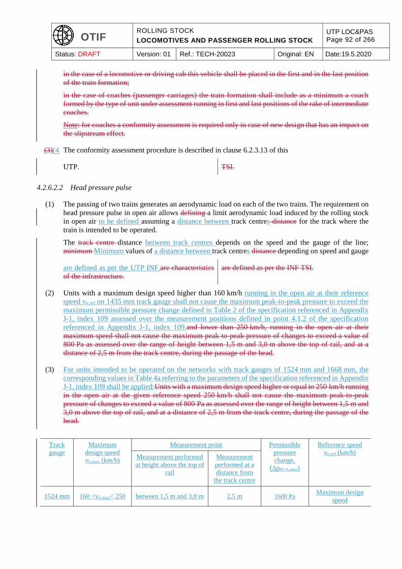
OTIF ROLLING STOCK
LOCOMOTIVES AND PASSENGER ROLLING STOCK
UTP LOC&PAS Page 92 of 266
Status: DRAFT Version: 01 Ref.: TECH-20023 Original: EN Date:19.5.2020
in the case of a locomotive or driving cab this vehicle shall be placed in the first and in the last position
of the train formation;
in the case of coaches (passenger carriages) the train formation shall include as a minimum a coach
formed by the type of unit under assessment running in first and last positions of the rake of intermediate
coaches.
Note: for coaches a conformity assessment is required only in case of new design that has an impact on
the slipstream effect.
(3)(4) The conformity assessment procedure is described in clause 6.2.3.13 of this
UTP. TSI.
4.2.6.2.2 Head pressure pulse
(1) The passing of two trains generates an aerodynamic load on each of the two trains. The requirement on
head pressure pulse in open air allows defining a limit aerodynamic load induced by the rolling stock
in open air to be defined assuming a distance between track centres distance for the track where the
train is intended to be operated.
The track centre distance between track centres depends on the speed and the gauge of the line;
minimum Minimum values of a distance between track centres distance depending on speed and gauge
are defined as per the UTP INF.are characteristics
of the infrastructure.
are defined as per the INF TSI.
(2) Units with a maximum design speed higher than 160 km/h running in the open air at their reference
speed vtr,ref on 1435 mm track gauge shall not cause the maximum peak-to-peak pressure to exceed the
maximum permissible pressure change defined in Table 2 of the specification referenced in Appendix
J-1, index 109 assessed over the measurement positions defined in point 4.1.2 of the specification
referenced in Appendix J-1, index 109.and lower than 250 km/h, running in the open air at their
maximum speed shall not cause the maximum peak-to-peak pressure of changes to exceed a value of
800 Pa as assessed over the range of height between 1,5 m and 3,0 m above the top of rail, and at a
distance of 2,5 m from the track centre, during the passage of the head.
(3) For units intended to be operated on the networks with track gauges of 1524 mm and 1668 mm, the
corresponding values in Table 4a referring to the parameters of the specification referenced in Appendix
J-1, index 109 shall be applied:Units with a maximum design speed higher or equal to 250 km/h running
in the open air at the given reference speed 250 km/h shall not cause the maximum peak-to-peak
pressure of changes to exceed a value of 800 Pa as assessed over the range of height between 1,5 m and
3,0 m above the top of rail, and at a distance of 2,5 m from the track centre, during the passage of the
head.
Track
gauge
Maximum
design speed
vtr,max (km/h)
Measurement point Permissible
pressure
change,
(Δp95 %,max)
Reference speed
vtr,ref (km/h) Measurement performed
at height above the top of
rail
Measurement
performed at a
distance from
the track centre
1524 mm 160 <vtr,max< 250 between 1,5 m and 3,0 m 2,5 m 1600 Pa Maximum design
speed
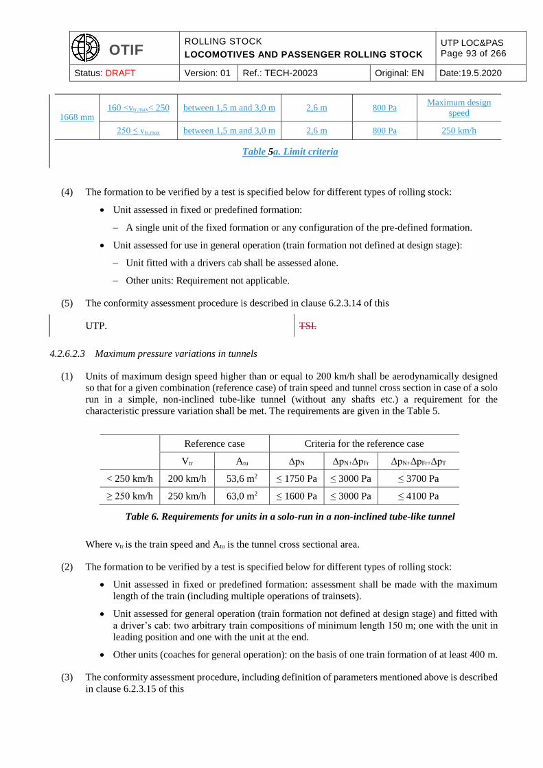
OTIF ROLLING STOCK
LOCOMOTIVES AND PASSENGER ROLLING STOCK
UTP LOC&PAS Page 93 of 266
Status: DRAFT Version: 01 Ref.: TECH-20023 Original: EN Date:19.5.2020
1668 mm 160 <vtr,max< 250 between 1,5 m and 3,0 m 2,6 m 800 Pa
Maximum design
speed
250 ≤ vtr,max between 1,5 m and 3,0 m 2,6 m 800 Pa 250 km/h
Table 5a. Limit criteria
(4) The formation to be verified by a test is specified below for different types of rolling stock:
Unit assessed in fixed or predefined formation:
A single unit of the fixed formation or any configuration of the pre-defined formation.
Unit assessed for use in general operation (train formation not defined at design stage):
Unit fitted with a drivers cab shall be assessed alone.
Other units: Requirement not applicable.
(5) The conformity assessment procedure is described in clause 6.2.3.14 of this
UTP. TSI.
4.2.6.2.3 Maximum pressure variations in tunnels
(1) Units of maximum design speed higher than or equal to 200 km/h shall be aerodynamically designed
so that for a given combination (reference case) of train speed and tunnel cross section in case of a solo
run in a simple, non-inclined tube-like tunnel (without any shafts etc.) a requirement for the
characteristic pressure variation shall be met. The requirements are given in the Table 5.
Reference case Criteria for the reference case
Vtr Atu ∆pN ∆pN+∆pFr ∆pN+∆pFr+∆pT
< 250 km/h 200 km/h 53,6 m2 ≤ 1750 Pa ≤ 3000 Pa ≤ 3700 Pa
≥ 250 km/h 250 km/h 63,0 m2 ≤ 1600 Pa ≤ 3000 Pa ≤ 4100 Pa
Table 6. Requirements for units in a solo-run in a non-inclined tube-like tunnel
Where vtr is the train speed and Atu is the tunnel cross sectional area.
(2) The formation to be verified by a test is specified below for different types of rolling stock:
Unit assessed in fixed or predefined formation: assessment shall be made with the maximum
length of the train (including multiple operations of trainsets).
Unit assessed for general operation (train formation not defined at design stage) and fitted with
a driver’s cab: two arbitrary train compositions of minimum length 150 m; one with the unit in
leading position and one with the unit at the end.
Other units (coaches for general operation): on the basis of one train formation of at least 400 m.
(3) The conformity assessment procedure, including definition of parameters mentioned above is described
in clause 6.2.3.15 of this
OTIF ROLLING STOCK
LOCOMOTIVES AND PASSENGER ROLLING STOCK
UTP LOC&PAS Page 94 of 266
Status: DRAFT Version: 01 Ref.: TECH-20023 Original: EN Date:19.5.2020
UTP. TSI.
4.2.6.2.4 Cross wind
(1) This requirement applies to units of maximum design speed higher than 140 km/h.
(2) For units of maximum design speed higher than 140 km/h and lower than 250 km/h the characteristic
wind curve (CWC) of the most sensitive vehicle shall be determined in accordance with the
specification referenced in Appendix J-1, index 37 and subsequently recorded in the technical file as
per clause 4.2.12.
(3) For units of maximum design speed equal to or higher than 250 km/h the crosswind effects shall be
evaluated according to one of the following methods:
(a) determined and complying with the specification of the EU Commission Decision
2008/232/EC13 clause 4.2.6.3, or
(b) determined by the assessment method of the specification referenced in Appendix J-1, index
37. The resulting characteristic wind curve of the most sensitive vehicle of the unit under
assessment shall be recorded in the technical documentation as per clause 4.2.12.
4.2.6.2.5 Aerodynamic effect on ballasted tracks
(1) This requirement applies to units of maximum design speed higher than or equal to 19250 km/h.
(2) The requirement on the aerodynamic effect of trains on ballasted tracks, in order to limit risks induced
by the projection of ballast (ballast pick up), is an open point.
4.2.7. External lights & visible and audible warning devices
4.2.7.1. External lights
(1) The colour green shall not be used for external light or illumination; this requirement is made to prevent
any confusion with fixed signals.
(2) This requirement is not applicable to lights with luminous of intensity not higher than 100 cd/m² that
are included in push buttons for the command of passenger doors (not continuously lit).
4.2.7.1.1 Head lights
(1) This clause applies to units fitted with a driver’s cab.
(2) Two white headlamps shall be provided at the front end of the train in order to give visibility for the
train driver.
(3) These head lamps shall be located:
13 Commission Decision 2008/232/EC of 21 February 2008 concerning a technical specification for interoperability relating to the ‘rolling stock’ sub-system of the trans-European high-speed rail system (notified under document C(2008) 648) (OJ L 84, 26.3.2008, p.132-392)
OTIF ROLLING STOCK
LOCOMOTIVES AND PASSENGER ROLLING STOCK
UTP LOC&PAS Page 95 of 266
Status: DRAFT Version: 01 Ref.: TECH-20023 Original: EN Date:19.5.2020
at the same height above the rail level, with their centres between 1500 and 2000 mm above the
rail level.
symmetrically compared to the centre-line of rails, and with a distance between their centres not
less than 1000 mm.
(4) The colour of head lamps shall be in accordance with the values specified in the specification referenced
in Appendix J-1, index 38, clause 5.3.3, table 1.
(5) Headlamps shall provide 2 luminous intensity levels: “dimmed headlamp” and “full-beam headlamp”.
For “dimmed headlamp”, the luminous intensity of headlamps measured along the optical axis of the
head lamp shall be in accordance with the values specified in the specification referenced in Appendix
J-1, index 38, clause 5.3.4, table 2, first line.
For “full-beam headlamp”, the minimum luminous intensity of headlamps measured along the optical
axis of the lamp shall be in accordance with the values specified in the specification referenced in
Appendix J-1, index 38, clause 5.3.4, table 2, first line.
(6) The installation of head lamps on the unit shall provide a means of alignment adjustment of their optical
axis when installed on the unit according to the specification referenced in Annex J-1, index 38, clause
5.3.5, to be used during maintenance activities.
(7) Additional head lamps may be provided (e.g. upper head lamps). These additional head lamps shall
fulfil the requirement on the colour of head lamps specified above in this clause.
Note: additional head lamps are not mandatory; their use at operational level may be subject to
restrictions.
4.2.7.1.2 Marker lights
(1) This clause applies to units fitted with a driver’s cab.
(2) Three white marker lamps shall be provided at the front end of the train in order to make the train
visible.
(3) Two lower marker lamps shall be located:
at the same height above the rail level, with their centres between 1500 and 2000 mm above the
rail level.
symmetrically compared to the centre-line of rails, and with a distance between their centres not
less than 1000 mm.
(4) The third marker lamp shall be located centrally above the two lower lamps, with a vertical separation
between their centers equal to or greater than 600 mm.
(5) It is permitted to use the same component for both head lights and marker lights.
(6) The colour of marker lamps shall be in accordance with the values specified in the specification
referenced in Appendix J-1, index 39, clause 5.4.3.1, table 4.
(7) The spectral radiation distribution of light from the marker lamps shall be in accordance with the values
specified in the specification referenced in Appendix J-1, index 39, clause 5.4.3.2.
OTIF ROLLING STOCK
LOCOMOTIVES AND PASSENGER ROLLING STOCK
UTP LOC&PAS Page 96 of 266
Status: DRAFT Version: 01 Ref.: TECH-20023 Original: EN Date:19.5.2020
(8) The luminous intensity of marker lamps shall be in accordance with the specification referenced in
Appendix J-1, index 39, clause 5.4.4, table 6.
4.2.7.1.3 Tail lights
(1) Two red tail lamps shall be provided at the rear end of units intended to be operated at the rear end of
the train in order to make the train visible.
(2) For units without driver’s cab assessed for general operation, the lamps may be portable lamps; in that
case, the type of portable lamp to be used shall be in accordance with the Appendix E of the “freight
wagons”
UTP; TSI;
the function shall be verified by design examination and type test at component level (interoperability
constituent “portable tail lamp”), but it is not required to provide the portable lamps.
(3) The tail lamps shall be located:
at the same height above the rail level, with their centres between 1 500 and 2000 mm above the
rail level.
symmetrically compared to the centre-line of rails, and with a distance between their centres not
less than 1000 mm.
(4) The colour of tail lamps shall be in accordance with the specification referenced in Appendix J-1, index
40, clause 5.5.3, table 7 (values).
(5) The luminous intensity of tail lamps shall in accordance with the specification referenced in Appendix
J-1, index 40, clause 5.5.4, table 8 (value).
4.2.7.1.4 Lamp controls
(1) This clause applies to units fitted with a driver’s cab.
(2) It shall be possible for the driver to control:
the head, marker lamps of the unit from the normal driving position;
the tail lamps of the unit from the cab.
This control may use independent command or combination of commands.
Note: where it is intended to use lights to inform of an emergency situation
Note: where it is intended to use lights to inform
of an emergency situation (operating rule, see
OPE TSI), this should be done only by means of
head lamps in flashing/blinking mode.
this should be done only by means of head lamps in flashing/blinking mode.
OTIF ROLLING STOCK
LOCOMOTIVES AND PASSENGER ROLLING STOCK
UTP LOC&PAS Page 97 of 266
Status: DRAFT Version: 01 Ref.: TECH-20023 Original: EN Date:19.5.2020
4.2.7.2. Horn (audible warning device)
4.2.7.2.1 General
(1) This clause applies to units fitted with a driving cab.
(2) Trains shall be fitted with warning horns in order to make the train audible.
(3) The notes of the audible warning horns are intended to be recognisable as being from a train and not be
similar to warning devices used in road transport or as factory or other common warning device. The
operation of the warning horns shall emit at least one of the following separate warning sounds below:
Sounding 1: the fundamental frequency of the separately sounded note shall be 660 Hz ± 30 Hz
(high note).
Sounding 2: the fundamental frequency of the separately sounded note shall be 370 Hz ± 20 Hz
(low note).
(4) In case additional warning sounds to one of the above (separate or combined) are provided on a
voluntary basis, their sound pressure level shall not be higher than values specified below in the clause
4.2.7.2.2.
Note: their use at operational level may be subject to restrictions.
4.2.7.2.2 Warning horn sound pressure levels
(1) The C weighted sound pressure level produced by each horn sounded separately (or in a group if
designed to sound simultaneously as a chord) when integrated on the unit shall be as defined in the
specification referenced in Appendix J-1, index 41.
(2) The conformity assessment procedure is specified in clause 6.2.3.17.
4.2.7.2.3 Protection
(1) Warning horns and their control systems shall be designed or protected, so far as is practicable, to
maintain their function when impacted by airborne objects such as debris, dust, snow, hail or birds.
4.2.7.2.4 Horn control
(1) It shall be possible for the driver to sound the audible warning device from all driving positions specified
in clause 4.2.9 of this
UTP. TSI.
OTIF ROLLING STOCK
LOCOMOTIVES AND PASSENGER ROLLING STOCK
UTP LOC&PAS Page 98 of 266
Status: DRAFT Version: 01 Ref.: TECH-20023 Original: EN Date:19.5.2020
4.2.8. Traction and electrical equipment
4.2.8.1. Traction performance
4.2.8.1.1 General
(1) The purpose of the train traction system is to ensure that the train is able to be operated at various speeds
up to its maximum service speed. The primary factors that influence traction performances are traction
power, train composition and mass, adhesion, track gradient and train running resistance.
(2) Unit performance for units fitted with traction equipment, and operated in various train formations shall
be defined so that the overall traction performance of the train can be derived.
(3) The traction performance is characterised by the maximum service speed and by the traction force
profile [force at wheel rim =F (speed)].
(4) The unit is characterised by its running resistance and its mass.
(5) The maximum service speed, the traction force profile and the running resistance are the unit
contributions necessary to define a timetable allowing a train to slot into the overall traffic pattern on a
given line, and are part of the technical documentation related to the unit described in clause 4.2.12.2
of this
UTP. TSI.
4.2.8.1.2 Requirements on performance
(1) This clause applies to units fitted with traction equipment.
(2) Unit traction force profiles [force at wheel rim = F(speed)] shall be determined by calculation; the unit
running resistance shall be determined by a calculation for the load case “design mass under normal
payload”, as defined in clause 4.2.2.10.
(3) Unit traction force profiles and running resistance shall be recorded in the technical documentation (see
clause 4.2.12.2).
(4) The design maximum speed shall be defined from the data above for the load case “design mass under
normal payload” on a level track; design maximum speed higher than 60 km/h shall be a multiple of
5 km/h.
(5) For units assessed in fixed or predefined formation, at the maximum service speed and on a level track,
the unit shall still be capable of an acceleration of at least 0.05 m/s² for the load case “design mass under
normal payload”. This requirement may be verified by calculation or by testing (acceleration
measurement) and applies for maximum design speed up to 350 km/h.
(6) Requirements regarding the traction cut-off required in case of braking are defined in the clause 4.2.4
of this
UTP. TSI.
(7) Requirements regarding availability of the traction function in case of fire on board are defined in the
clause 4.2.10.4.4.

OTIF ROLLING STOCK
LOCOMOTIVES AND PASSENGER ROLLING STOCK
UTP LOC&PAS Page 99 of 266
Status: DRAFT Version: 01 Ref.: TECH-20023 Original: EN Date:19.5.2020
Additional requirement for units assessed in fixed or predefined formation of maximum design
speed higher than or equal to 250 km/h:
(8) The mean acceleration on a level track, for the load case “design mass under normal payload”, shall be
of at least of:
0.40 m/s² from 0 to 40 km/h
0.32 m/s² from 0 to 120 km/h
0.17 m/s² from 0 to 160 km/h.
This requirement may be verified by calculation only or by testing (acceleration measurement)
combined with calculation.
(9) The design of the traction system shall assume a calculated wheel/rail adhesion not higher than:
0.30 at start up and very low speed
0.275 at 100 km/h
0.19 at 200 km/h
0.10 at 300 km/h.
(10) A single failure of power equipment affecting the traction capability shall not deprive the unit of more
than 50 % of its traction force.
4.2.8.2. Power supply
4.2.8.2.1 General
(1) Requirements applicable to rolling stock, and which interface with the Energy subsystem are dealt with
in this clause; therefore, this clause 4.2.8.2 applies to electric units.
(2) The
requirements in this UTP take into account
compatibility with
ENE TSI specifies
the following power systems: AC 25 kV 50 Hz system, AC 15 kV 16.7 Hz system, DC 3 kV system
and 1.5 kV system. As a consequence, requirements defined below are related to these 4 systems only,
and references to standards are valid for these 4 systems only.
4.2.8.2.2 Operation within range of voltages and frequencies
(1) Electric units shall be able to operate within the range of at least one of the systems “voltage and
frequency” defined
in point 4.2.8.2.1 - 2) of this UTP. The values and
limits of the voltage and frequency at the terminals
of the substation and at the pantograph are
presumed to comply with EN 50163:2004, clause
4.
in the ENE TSI, clause 4.2.3.
OTIF ROLLING STOCK
LOCOMOTIVES AND PASSENGER ROLLING STOCK
UTP LOC&PAS Page 100 of 266
Status: DRAFT Version: 01 Ref.: TECH-20023 Original: EN Date:19.5.2020
(2) The actual value of the line voltage shall be available in the driver cab in driving configuration.
(3) The systems ‘voltage and frequency’ for which the rolling stock is designed shall be recorded in the
technical documentation defined in clause 4.2.12.2 of this
UTP. TSI.
4.2.8.2.3 Regenerative brake with energy to the overhead contact line
(1) Electric units which return electrical energy to the overhead contact line in regenerative braking mode
shall comply with the specification referenced in Appendix J-1, index 42.
(2) It shall be possible to control the use of the regenerative brake.
4.2.8.2.4 Maximum power and current from the overhead contact line
(1) Electric units with power higher than 2 MW (including the declared fixed and predefined formations)
shall be equipped with power or current limitation function.
(2) Electric units shall be equipped with automatic regulation of the current within abnormal operation
condition regarding voltage; this regulation shall allow limiting the current to the ‘maximum current
against voltage’ specified in the specification referenced in Appendix J-1, index 43.
Note: a less restrictive limitation (lower value of coefficient ‘a’) may be used at operating level on a
particular network or line if agreed by the Infrastructure Manager.
(3) The maximum current assessed here above (rated current) shall be recorded in the technical
documentation defined in clause 4.2.12.2 of this
UTP. TSI.
4.2.8.2.5 Maximum current at standstill for DC systems
(1) For DC systems, the maximum current at standstill per pantograph shall be calculated and verified by
measurement.
(2) For the verification of compatibility between a unit
and the overhead contact line of DC systems, this
UTP assumes, without prejudice to specific cases,
that the overhead contact line:
is designed to sustain 300 A (for a 1.5 kV
supply system) and 200 A (for a 3 kV
supply system), per pantograph when the
train is at standstill, and
the current capacity at standstill is achieved
for the test value of static contact force
given in table 4 of clause 7.2 of EN
50367:2012, and
Limit values are specified in clause 4.2.5 of the
ENE TSI.
OTIF ROLLING STOCK
LOCOMOTIVES AND PASSENGER ROLLING STOCK
UTP LOC&PAS Page 101 of 266
Status: DRAFT Version: 01 Ref.: TECH-20023 Original: EN Date:19.5.2020
the OCL is designed taking into account the
temperature limits in accordance with EN
50119:2009 clause 5.1.2.
(3) The value measured and measurement conditions regarding the material of the contact wire shall be
recorded in the technical documentation defined in clause 4.2.12.2 of this
UTP. TSI.
4.2.8.2.6 Power factor
(1) The power factor design data of the train (including multiple operation of several units as defined in
clause 2.2 of this
(2) UTP) TSI)
shall be subject to a calculation to verify acceptance criteria set out in the specification referenced in
Appendix J-1, index 44.
4.2.8.2.7 System energy disturbances for ac systems
(1) An Electric unit shall not cause unacceptable overvoltage and other phenomena described in the
specification referenced in Appendix J-1, index 45, clause 10.1 (harmonics and dynamic effects) on the
overhead contact line.
(2) A compatibility study shall be done in accordance with the methodology defined in the specification
referenced in Appendix J-1, index 45, clause 10.3. The steps and hypothesis described in table 5 of the
same specification have to be defined by the applicant (column 3 “Concerned party” not applicable),
with input data presented as in Annex D of the same specification; the acceptance criteria shall be as
defined in clause 10.4 the same specification.
(3) All hypothesis and data considered for this compatibility study shall be recorded in the technical
documentation (see clause 4.2.12.2).
4.2.8.2.8 On-board energy measurement system
4.2.8.2.8.1 General
(1) The on-board energy measurement system (EMS) is the system for measurement of all active and
reactive electric energy taken from or returned (during regenerative braking) to the overhead contact
line (OCL) by the electric unit.
Fitting an EMS system is mandatory for vehicles
with an area of use including one or more
Contracting States that apply European Union law.
If an EMS system is fitted it shall comply with the
provisions of this UTP.

OTIF ROLLING STOCK
LOCOMOTIVES AND PASSENGER ROLLING STOCK
UTP LOC&PAS Page 102 of 266
Status: DRAFT Version: 01 Ref.: TECH-20023 Original: EN Date:19.5.2020
(2) The EMS shall include at least the following functions: Energy measurement function (EMF) as set out
in clause 4.2.8.2.8.2, data handling system (DHS) as set out in clause 4.2.8.2.8.3.On-board energy
measurement systems shall comply with requirements of the Appendix D of this
UTP. TSI.
(3) A suitable communication system will send the compiled energy billing data sets (CEBD) to an on-
ground data collecting system (DCS). The interface protocols and transferred data format between EMS
and DCS shall fulfil the requirements set out in point 4.2.8.2.8.4.This system is suitable for billing
purposes; the data provided by it shall be accepted for billing in all Member States.
(4) This system is suitable for billing purposes; the data sets defined in point 4.2.8.2.8.3(4) provided by this
system shall be accepted for billing in all Contracting States.The fitment of an on-board energy
measurement system, and of its on-board location function shall be recorded in the technical
documentation described in clause 4.2.12.2 of this
UTP; TSI;
the description of on-board to ground communication shall be part of the documentation.
(5) The EMS rated current and voltage shall be matched to the electric unit rated current and voltage; it
shall continue to function correctly when changing between several traction energy supply systems.The
maintenance documentation described in clause 4.2.12.3 of this
UTP. TSI.
(6) Data stored in the EMS shall be protected against loss of the power supply and the EMS shall be
protected from non-authorised access.shall include any periodic verification procedure, in order to
ensure the required accuracy level of the on-board energy measurement system during its lifetime.
(7) An on-board location function providing location data originated from an external source to the DHS
shall be provided in networks where such function is necessary for billing purposes only. In any case,
the EMS system shall be able to accommodate a compatible location function. If the location function
is provided, it shall fulfil the requirements set out in specification referenced in Appendix J-1, index
116.
(8) The fitment of an EMS, its on-board location function, the description of on-board to ground
communication and the metrological control including the accuracy class of the EMF shall be recorded
in the technical documentation described in clause 4.2.12.2 of this UTP.
(9) The maintenance documentation described in clause 4.2.12.3 of this UTP shall include any periodic
verification procedure to ensure the required accuracy level of the EMS during its lifetime.
4.2.8.2.8.2 Energy measurement function (EMF)
(1) The EMF shall ensure the measurement of the voltage and current, calculation of the energy and
production of energy data.
(2) The energy data produced by EMF shall have a time reference period of 5 minutes defined by the
Universal Time Coordinated (UTC) clock time at the end of each time reference period; originating
OTIF ROLLING STOCK
LOCOMOTIVES AND PASSENGER ROLLING STOCK
UTP LOC&PAS Page 103 of 266
Status: DRAFT Version: 01 Ref.: TECH-20023 Original: EN Date:19.5.2020
from the time stamp 00:00:00. It is permitted to use a shorter measuring period if the data can be
aggregated on-board into 5 minutes time reference period.
(3) The accuracy of EMF for active energy measurement shall comply with clauses 4.2.3.1 to 4.2.3.4 of the
specification referenced in Appendix J-1, index 117.
(4) Each device containing one or more functions of EMF shall indicate: metrological control, and its
accuracy class, according to the class designations specified in the specification referenced in clauses
4.3.3.4, 4.3.4.3 and 4.4.4.2 of the specification referenced in Appendix J-1, index 117.
(5) The conformity assessment of the accuracy is set out in clause 6.2.3.19a.
4.2.8.2.8.3 Data handling system (DHS)
(1) The DHS shall ensure the production of compiled energy billing data sets for energy billing purposes,
by merging data from the EMF with time data and, when required, geographical position, and storing it
ready to be sent to an on-ground data collecting system (DCS) by a communication system.
(2) The DHS shall compile the data without corrupting them and shall incorporate data storage with a
memory capacity sufficient to store the compiled data of at least 60 days continuous operation. The time
reference used shall be the same as in the EMF.
(3) The DHS shall have a capability to be interrogated locally on-board for audit and data recovery
purposes.
(4) The DHS shall produce compiled energy billing data sets, (CEBD), by merging the following data for
each time reference period:
unique EMS consumption point identification (CPID) as defined in the specification referenced
in Appendix J-1, index 118,
end time of each period, defined as year, month, day, hour, minute and second,
location data at the end of each period,
consumed/regenerated active and reactive (if appropriate) energy in each period, in units of watt-
hour (active energy) and var-hour (reactive energy) or their decimal-multiples.
(5) The conformity assessment of compilation and handling of data produced by DHS is set out in clause
6.2.3.19a.
4.2.8.2.8.4 Interface protocols and transferred data format between EMS and DCS
The data exchange between EMS and DCS shall fulfil the following requirements:
The application services (service layer) of the EMS shall comply with clause 4.3.3.1 of the
specification referenced in Appendix J-1, index 119.
User access rights for these application services shall comply with clause 4.3.3.3 of the
specification referenced in Appendix J-1, index 119.
The structure (data layer) for these application services shall comply with the XML schema as
defined in clause 4.3.4 of the specification referenced in Appendix J-1, index 119.
OTIF ROLLING STOCK
LOCOMOTIVES AND PASSENGER ROLLING STOCK
UTP LOC&PAS Page 104 of 266
Status: DRAFT Version: 01 Ref.: TECH-20023 Original: EN Date:19.5.2020
The message mechanism (message layer) for supporting these application services shall comply
with the methods and the XML schema in clause 4.3.5 of the specification referenced in
Appendix J- 1, index 119.
The application protocols for supporting the message mechanism shall comply with clause 4.3.6
of the specification referenced in Appendix J-1, index 119.
The EMS shall use at least one of the communication architectures in clause 4.3.7 of the
specification referenced in Appendix J-1, index 119.
4.2.8.2.9 Requirements linked to pantograph
4.2.8.2.9.1 Working range in height of pantograph
4.2.8.2.9.1.1 Height of interaction with contact wires (RST level)
The installation of a pantograph on an Electric unit shall allow mechanical contact from at least one of
the contact wires at heights between:
(1) 4800 mm and 6500 mm above rail level for tracks designed in accordance with the gauge GC.
(2) 4500 mm and 6500 mm above rail level for tracks designed in accordance with the gauge GA/GB.
(3) 5550 mm and 6800 mm above rail level for tracks designed in accordance with the gauge T (track gauge
system 1520 mm)
(4) 5600 mm and 6600 mm above rail level designed in accordance with the gauge FIN1 (track gauge
system 1524 mm).
Note: current collection is verified according to clauses 6.1.3.7 and 6.2.3.21 of this
UTP, TSI,
specifying heights of contact wire for tests; however, current collection at low speed is assumed to be
possible from a contact wire at any of the heights specified above.
(5) 3920 mm and 5700 mm above rail level for electric units designed to be operated on the 1500 V DC
system in accordance with the IRL gauge (track gauge system 1600 mm).
4.2.8.2.9.1.2 Working range in height of pantograph (IC level)
(1) Pantographs shall have a working range of at least 2000 mm.
(2) The characteristics to be verified shall be in accordance with the requirements of the specification
referenced in Appendix J-1, index 46.
4.2.8.2.9.2 Pantograph head geometry (IC level)
(1) For electric units designed to be operated on other track gauge systems than 1520 mm or 1600 mm
system, at least one of the pantograph(s) to be installed shall have a head geometry type compliant with
one of the two specifications given in the clauses 4.2.8.2.9.2.1 and 2 below.
OTIF ROLLING STOCK
LOCOMOTIVES AND PASSENGER ROLLING STOCK
UTP LOC&PAS Page 105 of 266
Status: DRAFT Version: 01 Ref.: TECH-20023 Original: EN Date:19.5.2020
(2) For electric units designed to be operated solely on the 1520 mm system, at least one of the
pantograph(s) to be installed shall have a head geometry type compliant with one of the three
specifications given in the clauses 4.2.8.9.2.1, 2 and 3 below.
(2a) For electric units designed to be operated solely on the 1600 mm system, at least one of the pantographs
to be installed shall have a head geometry type compliant with the specifications given in the clauses
4.2.8.2.9.2.13a below.
(3) The type(s) of pantograph head geometry that an electric unit is equipped with shall be recorded in the
technical documentation defined in clause 4.2.12.2 of this
UTP. TSI.
(4) The width of pantograph head shall not exceed 0.65 meters.
(5) Pantograph heads fitted with contact strips having independent suspensions shall be compliant with the
specification referenced in Appendix J-1, index 47.
(6) Contact between contact wire and pantograph head is permitted outside the contact strips and within
the whole conducting range over limited line sections under adverse conditions, e.g. coincidence of
vehicle swaying and high winds.
Conducting range and the minimum length of contact strip are specified below as part of the pantograph
head geometry.
4.2.8.2.9.2.1 Pantograph head geometry type 1600 mm
(1) The pantograph head geometry shall be as depicted in the specification referenced in Appendix J-1,
index 48.
4.2.8.2.9.2.2 Pantograph head geometry type 1950 mm
(1) The pantograph head geometry shall be as depicted in the specification referenced in Appendix J-1,
index 49.
(2) Insulated or non-insulated materials for the horns are both permitted.
4.2.8.2.9.2.3 Pantograph head geometry type 2000/2260 mm
(1) The profile of the pantograph head shall be as depicted below:
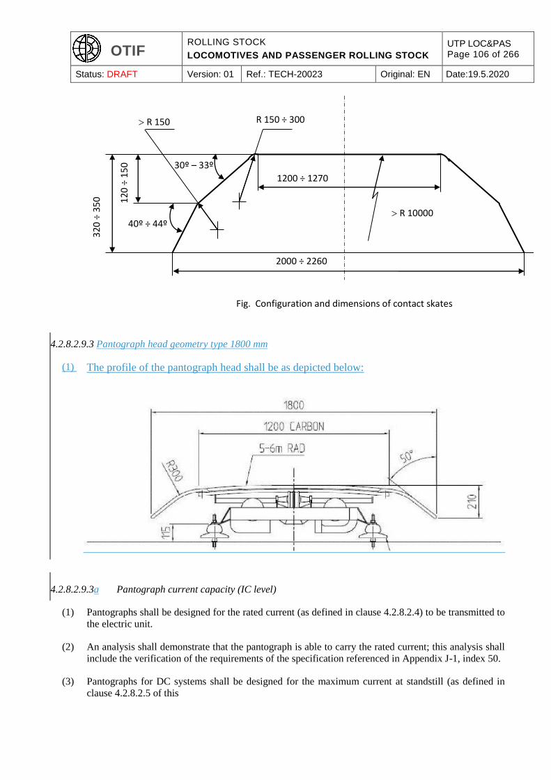
OTIF ROLLING STOCK
LOCOMOTIVES AND PASSENGER ROLLING STOCK
UTP LOC&PAS Page 106 of 266
Status: DRAFT Version: 01 Ref.: TECH-20023 Original: EN Date:19.5.2020
4.2.8.2.9.3 Pantograph head geometry type 1800 mm
(1) The profile of the pantograph head shall be as depicted below:
4.2.8.2.9.3a Pantograph current capacity (IC level)
(1) Pantographs shall be designed for the rated current (as defined in clause 4.2.8.2.4) to be transmitted to
the electric unit.
(2) An analysis shall demonstrate that the pantograph is able to carry the rated current; this analysis shall
include the verification of the requirements of the specification referenced in Appendix J-1, index 50.
(3) Pantographs for DC systems shall be designed for the maximum current at standstill (as defined in
clause 4.2.8.2.5 of this
Fig. Configuration and dimensions of contact skates
320
÷ 3
50
2000 ÷ 2260
30º – 33º
40º ÷ 44º
120
÷ 1
50
1200 ÷ 1270
R 150 ÷ 300 R 150
R 10000

OTIF ROLLING STOCK
LOCOMOTIVES AND PASSENGER ROLLING STOCK
UTP LOC&PAS Page 107 of 266
Status: DRAFT Version: 01 Ref.: TECH-20023 Original: EN Date:19.5.2020
UTP. TSI.
4.2.8.2.9.4 Contact strip (IC level)
(1) Contact strips are the replaceable parts of the pantograph head, which are in direct contact with the
contact wire.
4.2.8.2.9.4.1 Contact strip geometry
(1) Contact strips shall be geometrically designed to be fitted to one of the pantograph head geometries
specified in clause 4.2.8.2.9.2.
4.2.8.2.9.4.2 Contact strip material
(1) Material used for the contact strips shall be mechanically and electrically compatible with the contact
wire material
installed on the lines where the unit is intended to
run,
(as specified in clause 4.2.14 of the ENE TSI),
in order to ensure proper current collection and to avoid excessive abrasion of the surface of the contact
wires, thereby minimising wear of both contact wires and contact strips.
It is the responsibility of the Competent Authority
to ensure that information about the contact strip
material is provided to the applicant.
(2) Plain carbon or impregnated carbon with additive material shall be permitted.
Where a metallic additive material is used, the metallic content of the carbon contact strips shall be
copper or copper alloy and shall not exceed a content of 35 % by weight where used on AC lines and
of 40 % where used on DC lines.
Pantographs assessed against this
UTP TSI
shall be fitted with contact strips of a material mentioned above.
(3) Additionally, contact strips of other material or higher percentage of metallic contents or impregnated
carbon with cladded copper are allowed (if permitted
on the lines where the unit is intended to run) in the infrastructure register)
provided that:
they are referenced in recognised standards, with mention of restrictions if any, or
they have been subject to a test of suitability for use (see clause 6.1.3.8).
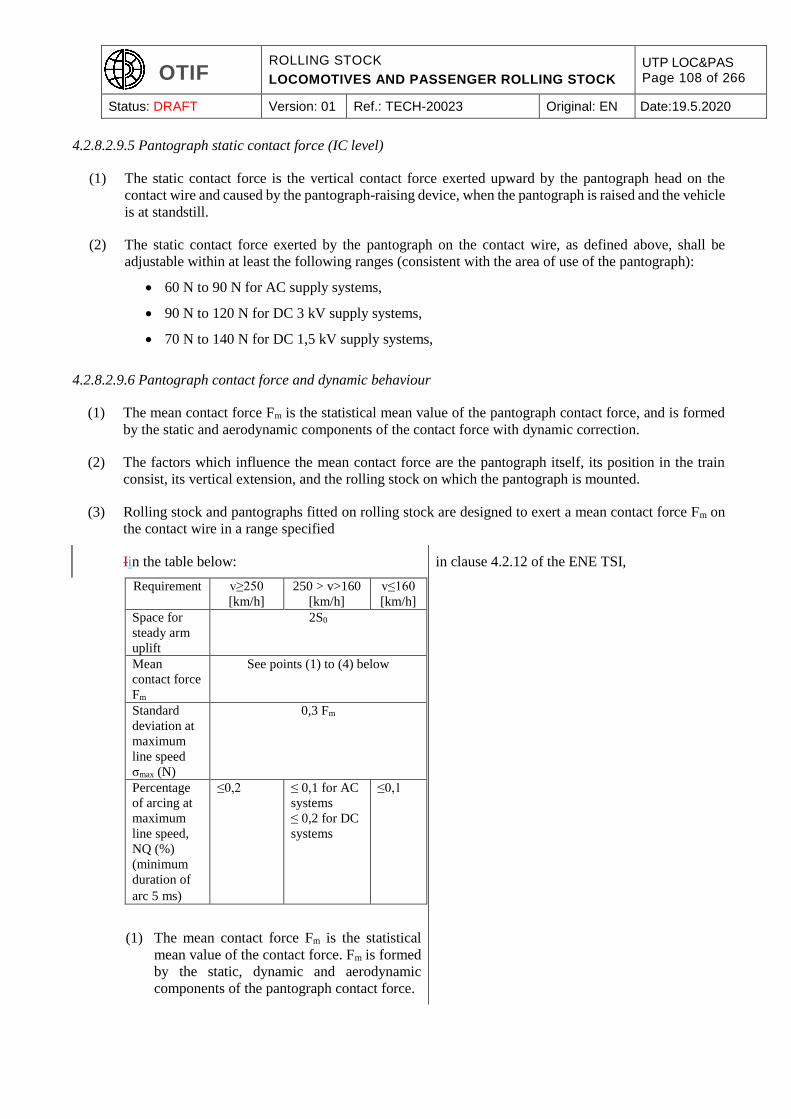
OTIF ROLLING STOCK
LOCOMOTIVES AND PASSENGER ROLLING STOCK
UTP LOC&PAS Page 108 of 266
Status: DRAFT Version: 01 Ref.: TECH-20023 Original: EN Date:19.5.2020
4.2.8.2.9.5 Pantograph static contact force (IC level)
(1) The static contact force is the vertical contact force exerted upward by the pantograph head on the
contact wire and caused by the pantograph-raising device, when the pantograph is raised and the vehicle
is at standstill.
(2) The static contact force exerted by the pantograph on the contact wire, as defined above, shall be
adjustable within at least the following ranges (consistent with the area of use of the pantograph):
60 N to 90 N for AC supply systems,
90 N to 120 N for DC 3 kV supply systems,
70 N to 140 N for DC 1,5 kV supply systems,
4.2.8.2.9.6 Pantograph contact force and dynamic behaviour
(1) The mean contact force Fm is the statistical mean value of the pantograph contact force, and is formed
by the static and aerodynamic components of the contact force with dynamic correction.
(2) The factors which influence the mean contact force are the pantograph itself, its position in the train
consist, its vertical extension, and the rolling stock on which the pantograph is mounted.
(3) Rolling stock and pantographs fitted on rolling stock are designed to exert a mean contact force Fm on
the contact wire in a range specified
Iin the table below:
Requirement v≥250
[km/h]
250 > v>160
[km/h]
v≤160
[km/h]
Space for
steady arm
uplift
2S0
Mean
contact force
Fm
See points (1) to (4) below
Standard
deviation at
maximum
line speed
σmax (N)
0,3 Fm
Percentage
of arcing at
maximum
line speed,
NQ (%)
(minimum
duration of
arc 5 ms)
≤0,2 ≤ 0,1 for AC
systems
≤ 0,2 for DC
systems
≤0,1
in clause 4.2.12 of the ENE TSI,
(1) The mean contact force Fm is the statistical
mean value of the contact force. Fm is formed
by the static, dynamic and aerodynamic
components of the pantograph contact force.
OTIF ROLLING STOCK
LOCOMOTIVES AND PASSENGER ROLLING STOCK
UTP LOC&PAS Page 109 of 266
Status: DRAFT Version: 01 Ref.: TECH-20023 Original: EN Date:19.5.2020
(2) The ranges of Fm for each of the power supply
systems are defined in EN 50367:2012 Table
6.
(3) The overhead contact lines shall be designed
to be capable of sustaining the upper design
limit of Fm given in EN 50367:2012 Table 6.
(4) The curves apply to speeds up to 320 [km/h].
For speeds above 320 [km/h] procedures set
out in point 6.1.3 shall apply.
S0 is the calculated, simulated or measured
uplift of the contact wire at a steady arm,
generated in normal operating conditions with
one or more pantographs with the upper limit
of Fm at the maximum line speed. When the
uplift of the steady arm is physically limited
due to the overhead contact line design, it is
permissible for the necessary space to be
reduced to 1.5 S0 (refer to EN 50119:2009
clause 5.10.2).
Maximum force (Fmax) is usually within the
range of Fm plus three standard deviations
σmax; higher values may occur at particular
locations and are given in EN 50119:2009,
Table 4 clause 5.2.5.2. For rigid components
such as section insulators in overhead contact
line systems, the contact force can increase up
to a maximum of 350 N,.
in order to ensure current collection quality without undue arcing and to limit wear and hazards to
contact strips. Adjustment of the contact force is made when dynamic tests are performed.
(4) The verification at interoperability constituent level shall validate the dynamic behaviour of the
pantograph itself, and its capability to collect current from a
TSI compliant
overhead contact line; the conformity assessment procedure specified in clause 6.1.3.7.
(5) The verification at rolling stock subsystem level (integration in a particular vehicle) shall allow to adjust
the contact force, taking into account aerodynamic effects due to the rolling stock and the position of
the pantograph in the unit or train fixed or predefined formation(s); the conformity assessment procedure
specified in clause 6.2.3.20.
(6) The According to the ENE TSI, the
range of mean contact force Fm is not harmonised for overhead contact lines designed for speed higher
than 320 km/h. Therefore electric units can only be assessed against this
UTP TSI
OTIF ROLLING STOCK
LOCOMOTIVES AND PASSENGER ROLLING STOCK
UTP LOC&PAS Page 110 of 266
Status: DRAFT Version: 01 Ref.: TECH-20023 Original: EN Date:19.5.2020
regarding the dynamic behaviour of the pantograph up to the speed of 320 km/h.
For the speed range above 320 km/h up to the maximum speed (if higher than 320 km/h), the procedure
for innovative solutions described in
this UTP article 10 and Chapter 6 of this TSI
shall apply.
4.2.8.2.9.7 Arrangement of pantographs (RST level)
(1) It is permissible for more than one pantograph to be simultaneously in contact with the overhead contact
line equipment.
(2) The number of pantographs and their spacing shall be designed taking into consideration the
requirements of current collection performance, as defined in clause 4.2.8.2.9.6 above.
(3) Where the spacing of 2 consecutive pantographs in fixed or pre-defined formations of the assessed unit
is less than the spacing
as set out in the tables below:
Design speed (km/h) AC Minimum distance (m)
Type A B C
v≥250 200
160 < v <250 200 85 35
120 < v ≤ 160 85 85 35
80 < v ≤ 120 20 15 15
v ≤ 80 8 8 8
Design speed (km/h) 3 kV DC Minimum
distance (m)
Type A B C
v≥250 200
160 < v <250 200 115 35
120 < v ≤ 160 20 20 20
80 < v ≤ 120 20 15 15
v ≤ 80 8 8 8
Design speed (km/h) 1,5 kV DC Minimum
distance (m)
Type A B C
v≥250 200 200 35
160 < v <250 200 85 35
120 < v ≤ 160 85 35 20
80 < v ≤ 120 35 20 15
v ≤ 80 20 8 8
shown in clause 4.2.13 of the ENE TSI,
for the selected OCL design distance type, or where more than 2 pantographs are simultaneously in
contact with the overhead contact line equipment, it shall be demonstrated by testing that the current
OTIF ROLLING STOCK
LOCOMOTIVES AND PASSENGER ROLLING STOCK
UTP LOC&PAS Page 111 of 266
Status: DRAFT Version: 01 Ref.: TECH-20023 Original: EN Date:19.5.2020
collection quality as defined in clause 4.2.8.2.9.6 above is met for the poorest performing pantograph
(identified by simulations to be performed prior to that test).
(4) The OCL design distance type (A, B or C as defined in
point 3 of this section) the clause 4.2.13 of the ENE TSI)
selected (and therefore used for the test) shall be recorded in the technical documentation (see clause
4.2.12.2).
4.2.8.2.9.8 Running through phase or system separation sections (RST level)
(1) Trains shall be designed to be able to move from one power supply system and from one phase section
to an adjacent one
without bridging either system or phase separation
sections.
For the verification of compatibility between a unit
and the overhead contact line, this UTP assumes,
without prejudice to specific cases, that the phase
or system separation sections are as set out below:
Phase separation sections
General
The design of phase separation sections is deemed
to ensure that trains can move from one section to
an adjacent one without bridging the two phases.
Power consumption of the train (traction,
auxiliaries and no-load current of the transformer)
is deemed to be brought to zero before entering the
phase separation section. Adequate means (except
for the short separation section) are deemed to be
provided to allow a train that is stopped within the
phase separation section to be restarted.
The overall length D of neutral sections is defined
in EN 50367:2012, clause 4. For the calculation of
D clearances in accordance with EN 50119:2009,
clause 5.1.3 and an uplift of S0 are deemed to be
taken into account.
Lines with speed v≥250 [km/h]
Two types of designs of phase separation sections
are deemed to be taken into account, either:
a) a phase separation design where all the
pantographs of the longest TSI compliant
trains are within the neutral section. The
overall length of the neutral section is
deemed to be at least 402 m. For detailed
requirements see EN 50367:2012, Annex
A.1.2, or
(as described in clauses 4.2.15 and 4.2.16 of the
ENE TSI) without bridging either system or phase
separation section.
OTIF ROLLING STOCK
LOCOMOTIVES AND PASSENGER ROLLING STOCK
UTP LOC&PAS Page 112 of 266
Status: DRAFT Version: 01 Ref.: TECH-20023 Original: EN Date:19.5.2020
b) a shorter phase separation with three
insulated overlaps as shown in EN
50367:2012, Annex A.1.4. The overall
length of the neutral section is deemed to be
less than 142 m including clearances and
tolerances.
Lines with speed v<250 [km/h]
The design of separation sections is deemed to be
in line with solutions as described in EN
50367:2012 Annex A.1. Where an alternative
solution is used, the alternative is deemed to be at
least as reliable.
System separation sections
General
The design of system separation sections is deemed
to ensure that trains can move from one power
supply system to an adjacent different power
supply system without bridging the two systems.
There are two methods for traversing system
separation sections:
a) with pantograph raised and touching the
contact wire,
b) with pantograph lowered and not touching
the contact wire.
The overall length D of neutral sections is deemed
to be in line with EN 50367:2012, clause 4. For the
calculation of D clearances in accordance with EN
50119:2009, clause 5.1.3 and an uplift of S0 are
deemed to be taken into account.
Pantographs raised
Power consumption of the train (traction,
auxiliaries and no-load current of the transformer)
shall be brought to zero before entering the system
separation section. If system separation sections
are traversed with pantographs raised to the contact
wire, their functional design is deemed to be
realised as follows:
a) the geometry of different elements of the
overhead contact line shall prevent
pantographs short-circuiting or bridging
both power systems,
b) provision shall be made in the energy
subsystem to avoid bridging of both
adjacent power supply systems should the
opening of the on-board circuit breaker(s)
fail,
OTIF ROLLING STOCK
LOCOMOTIVES AND PASSENGER ROLLING STOCK
UTP LOC&PAS Page 113 of 266
Status: DRAFT Version: 01 Ref.: TECH-20023 Original: EN Date:19.5.2020
c) variation in contact wire height along the
entire separation section shall fulfil the
requirements set in EN 50119:2009 clause
5.10.3.
Pantographs lowered
If a system separation section is traversed with
pantographs lowered, it is deemed to be designed
so as to avoid the electrical connection of the two
power supply systems by an unintentionally raised
pantograph.
(2) Electric units designed for several power supply systems shall, when running through system separation
sections, recognise automatically the voltage of the power supply system at the pantograph.
(3) When running through phase or system separation sections, it shall be possible to bring the power
consumption of the unit to zero.
As set out in Appendix K, iIt shall be the task of
the infrastructure managerCompetent Authority of
each Contracting State to make the relevant
information about the infrastructure available to
the applicant, such as
The infrastructure register gives information on
the permitted pantographs position: lowered or raised (with permitted pantograph arrangements) when
running through systems or phase separation sections.
(4) Electric units of maximum design speed higher than or equal to 250 km/h shall be fitted with an on-
board TCMS (train control and monitoring system) able to receive from the ground the information
related to the location of the separation section, and the subsequent commands to the control of the
pantograph and main circuit breaker shall be triggered automatically by the TCMS of the unit, without
intervention of the driver.
(5) Units intended to operate on lines that are fitted with the ETCS track side system for control-command
and signalling shall be fitted with an on-board TCMS (train control and monitoring system) able to
receive from the ETCS system the information related to the location of the separation section
with reference to Appendix J-2, index 3 of this
UTP),
as described in Annex A Index 7 of CCS TSI);
for units of maximum design speed lower than 250 km/h, the subsequent commands are not required to
be automatic, but information on section separation provided by ETCS shall be displayed on-board for
the intervention of the driver.
4.2.8.2.9.9 Insulation of pantograph from the vehicle (RST level)
(1) The pantographs shall be assembled on an electric unit in a way that ensures the current path from
collector head to vehicle equipment is insulated. The insulation shall be adequate for all system voltages
the unit is designed for.
OTIF ROLLING STOCK
LOCOMOTIVES AND PASSENGER ROLLING STOCK
UTP LOC&PAS Page 114 of 266
Status: DRAFT Version: 01 Ref.: TECH-20023 Original: EN Date:19.5.2020
4.2.8.2.9.10 Pantograph lowering (RST level)
(1) Electric units shall be designed to lower the pantograph in a period meeting the requirements of the
specification referenced in Appendix J-1, index 51, clause 4.7 (3 seconds) and to the dynamic insulating
distance according to the specification referenced in Appendix J-1, index 52 either by initiation by the
driver or by a train control function (including CCS functions).
(2) The pantograph shall lower to the stowed position in less than 10 seconds.
When lowering the pantograph, the main circuit breaker shall previously be opened automatically.
(3) If an electric unit is equipped with an automatic dropping device (ADD) that lowers the pantograph in
case of a collector head failure, the ADD shall meet the requirements of the specification referenced in
Appendix J-1, index 51, clause 4.8.
(4) Electric units of maximum design speed higher than 160 km/h shall be equipped with an ADD.
(5) Electric units that require more than one pantograph raised in operation and of maximum design speed
higher than 120 km/h shall be equipped with an ADD.
(6) Other electric units are permitted to be equipped with an ADD.
4.2.8.2.10 Electrical protection of the train
(1) Electric units shall be protected against internal short – circuits (from inside the unit).
(2) The location of the main circuit breaker shall be such as to protect the on-board high voltage circuits,
including any high voltage connections between vehicles. The pantograph, the main circuit breaker, and
the high voltage connection between them shall be located on the same vehicle.
(3) Electric units shall protect themselves against short overvoltages, temporary overvoltages and
maximum fault current. To meet this requirement, electrical protection coordination design of the unit
shall comply with the requirements defined in the specification referenced in Appendix J-1, index 53.
4.2.8.3. Diesel and other thermal traction system
(1) Diesel engines are to comply with the Union legislation concerning exhaust (composition, limit values).
4.2.8.4. Protection against electrical hazards
(1) Rolling stock and its electrically live components shall be designed such that direct or indirect contact
with train staff and passenger is prevented, both in normal cases and in cases of equipment failure.
Provisions described in the specification referenced in Appendix J-1, index 54 shall be applied in order
to meet this requirement.
4.2.9. Driver’s Cab and driver-machine interface
(1) The requirements specified in this clause apply to units fitted with a driver’s cab.
OTIF ROLLING STOCK
LOCOMOTIVES AND PASSENGER ROLLING STOCK
UTP LOC&PAS Page 115 of 266
Status: DRAFT Version: 01 Ref.: TECH-20023 Original: EN Date:19.5.2020
4.2.9.1. Driver´s Cab
4.2.9.1.1 General
(1) The driver’s cabs shall be designed to permit operation by a single driver.
(2) The maximum noise level allowed in the cab is specified in the
UTP NOI. NOI TSI.
4.2.9.1.2 Access and egress
4.2.9.1.2.1 Access and egress in operating conditions
(1) The driver’s cab shall be accessible from both sides of the train from 200 mm below top of rail.
(2) It is permissible for this access to be either directly from the exterior, using a cab external door, or
through the area at the rear of the cab. In the latter case, requirements defined in this clause shall apply
to the external accesses used for access to the cab on either side of the vehicle.
(3) The means for the train crew to access in and to egress out of the cab, such as footsteps, handrails or
opening handles, shall allow safe and easy usage by being of dimensions (pitch, width, spacing, shape)
to be assessed by reference to recognised standards; they shall be designed with consideration of
ergonomic criteria in relation with their use. Footsteps shall have no sharp edges causing obstacles for
the shoes of the train crew.
(4) Rolling stock with external walkways shall be equipped with handrails and foot bars (kicking strips) for
driver safety when accessing the cab.
(5) Driver’s cab external doors shall open in such a way that they remain within the intended reference
profile (see clause 4.2.3.1 of this
UTP) TSI)
when opened (the unit being at standstill).
(6) Driver’s cab external doors shall have a minimum clearance of 1675 x 500 mm when accessible by
foot-steps, or of 1750 x 500 mm when accessible on floor level.
(7) Interior doors used by the train crew to access the cab shall have a minimum clearance of 1700 x
430 mm.
(8) For both driver’s cab external doors and internal doors, in case they are positioned perpendicular to and
against the side of the vehicle, it is allowed to have the clearance width in the upper part reduced (angle
on the top-outer side) due to the gauge of the vehicle; this reduction shall be strictly limited to the gauge
constraint in the upper part and shall not lead to a clearance width on top side of the door lower than
280 mm.
(9) The driver’s cab and its access shall be designed so that the train crew is able to prevent the cab being
accessed by non-authorised persons, whether the cab is occupied or not, and so that a cab occupant is
able to go outside of a cab without having to use any tool or key.
OTIF ROLLING STOCK
LOCOMOTIVES AND PASSENGER ROLLING STOCK
UTP LOC&PAS Page 116 of 266
Status: DRAFT Version: 01 Ref.: TECH-20023 Original: EN Date:19.5.2020
(10) Access to the driver’s cab shall be possible without any energy supply available on board. Cab external
doors shall not open unintentionally.
4.2.9.1.2.2 Driver’s cab emergency exit
(1) In an emergency situation, evacuation of the train crew from the driver’s cab and access to the interior
of the cab by the rescue services shall be possible on both sides of the cab by using one of the following
emergency exit means: cab external doors (access directly from the exterior, as defined in clause
4.2.9.1.2.1 above) or side windows or emergency hatches.
(2) In all cases, the emergency exit means shall provide a minimum clearance (free area) of 2000 cm² with
a minimum inner dimension of 400 mm to allow the release of trapped persons.
(3) Front position driver’s cabs shall have at least an interior exit; this exit shall give access to an area of a
minimum length of 2 metres, of a minimum clearance identical to those specified in clause 4.2.9.1.2.1,
points (7) and (8), and this area (including its floor) shall be free of any obstruction to the escape of the
driver; the above area shall be located on-board the unit, and can be an interior area or an area opened
to the outside.
4.2.9.1.3 External visibility
4.2.9.1.3.1 Front visibility
(1) The driver’s cab shall be designed to allow the driver at his seated driving position a clear and
unobstructed line of sight in order to distinguish fixed signals set to both the left and right of a straight
track, and in curves with a radius of 300 m or more, under the conditions defined in Appendix F.
(2) The above requirement shall also be met from the standing driving position under conditions defined in
the Appendix F, on locomotives and on driving coaches, in case these coaches are intended to be also
operated by a driver in standing position.
(3) For locomotives with central cab and for OTMs, in order to ensure the visibility of low signals, it is
permitted that the driver moves to several different positions in the cab in order to meet the above
requirement; it is not required to meet the requirement from the seated driving position.
4.2.9.1.3.2 Rear and side view
(1) The cab shall be designed to allow the driver to have a rear view of each side of the train at stand still;
this requirement is permitted to be met by one of the following means: opening side windows or panel
at each side of the cab, exterior mirrors, camera system.
(2) In case of opening side windows or panel used as that means to meet the requirement above in point
(1), the opening shall be sufficiently large for the driver to put his head through the aperture;
additionally, for locomotives and driving coaches intended to be used in a train composition with a
locomotive, the design shall allow the driver at the same time to operate the emergency brake.
4.2.9.1.4 Interior layout
(1) The interior layout of the cab shall take into account the anthropometric measurements of the driver as
set out in the Appendix E.
OTIF ROLLING STOCK
LOCOMOTIVES AND PASSENGER ROLLING STOCK
UTP LOC&PAS Page 117 of 266
Status: DRAFT Version: 01 Ref.: TECH-20023 Original: EN Date:19.5.2020
(2) Freedom of movement of personnel in the cab interior shall not be inhibited by obstructions.
(3) The cab floor corresponding to the working area of the driver (access to the cab and foot rest excluded)
shall be without any step.
(4) The interior layout shall allow both seated and standing driving positions on locomotives and on driving
coaches, in case these coaches are intended to be also operated by a driver in standing position.
(5) The cab shall be equipped with at least one driver’s seat (see clause 4.2.9.1.5) and additionally with a
seat not considered as a driving position for possible accompanying crew.
4.2.9.1.5 Driver’s seat
Requirements at component level:
(1) The driver’s seat shall be designed in such a way that it allows him to undertake all normal driving
functions in a seated position, taking into account the anthropometric measurements of the driver as set
out in the Appendix E. It shall allow for correct posture of the driver from the physiological point of
view.
(2) It shall be possible for the driver to adjust the seat position in order to meet the reference position of
eyes for external visibility, as defined in clause 4.2.9.1.3.1.
(3) Ergonomics and health aspects shall be considered in the design of the seat, and its use by the driver.
Requirements for integration in the driver’s cab:
(4) The mounting of the seat in the cab shall allow to meet external visibility requirements as specified in
clause 4.2.9.1.3.1 above by using the range of adjustment provided by the seat (at component level); it
shall not alter ergonomics and health aspects and the use of the seat by the driver.
(5) The seat shall not constitute an obstacle for the driver to escape in case of emergency.
(6) The mounting of the driver’s seat in locomotives, and in driving coaches, in case these coaches are
intended to also be operated by a driver in standing position shall allow adjustment to get the necessary
free space needed for the standing driving position.
4.2.9.1.6 Driver’s desk- Ergonomics
(1) The driver’s desk and its operating equipment and controls shall be arranged to enable, in the most
commonly used driving position, the driver to keep a normal posture, without hampering his freedom
of movement, taking into account the anthropometric measurements of the driver as set out in the
Appendix E.
(2) To allow the display on the driver’s desk surface of paper documents required during driving, a reading
zone of minimum size 30 cm width per 21 cm high shall be available in front of the driver’s seat.
(3) Operating and control elements shall be clearly marked, so that they are identifiable by the driver.
OTIF ROLLING STOCK
LOCOMOTIVES AND PASSENGER ROLLING STOCK
UTP LOC&PAS Page 118 of 266
Status: DRAFT Version: 01 Ref.: TECH-20023 Original: EN Date:19.5.2020
(4) If the traction and/or braking effort is set-up by a lever (combined one or separated ones), the “tractive
effort” shall increase by pushing the lever forwards, and the “braking effort” shall increase by drawing
the lever towards the driver.
If there is a position for emergency braking, it shall be clearly distinguished from those of the other
positions of the lever (e.g. by a notch).
4.2.9.1.7 Climate control and air quality
(1) The air in the cab shall be renewed to keep the CO2 concentration to the levels specified in the clause
4.2.5.8 of this
UTP. TSI.
(2) At the seated driving position (as defined in the clause 4.2.9.1.3) of the driver’s head and shoulders,
there shall be no air flows caused by the ventilation system having an air velocity exceeding the limit
value recognised to ensure a proper working environment.
4.2.9.1.8 Internal lighting
(1) Cab general lighting shall be provided on driver’s command in all normal operational modes of the
rolling stock (included “switched off”). Its luminosity on desk level shall be higher than 75 lux at the
level of the driver’s desk, except for OTMs for which it shall be higher than 60 lux.
(2) Independent lighting of the driver’s desk reading zone shall be provided on driver’s command, and shall
be adjustable up to a value higher than 150 lux.
(3) An independent lighting of instruments shall be provided, and shall be adjustable.
(4) In order to prevent any dangerous confusion with outside operational signalling, no green lights or green
illumination are permitted in a driver’s cab, except for
cab signalling systems of which the design predates
the entry into force of this UTP.
existing class B cab signalling systems (as defined
in the CCS TSI).
4.2.9.2. Windscreen
4.2.9.2.1 Mechanical characteristics
(1) The dimension, location, shape and finishes (including those for maintenance purpose) of the windows
shall not inhibit the drivers external view (as defined in clause 4.2.9.1.3.1) and shall support the driving
task.
(2) The driver’s cab windscreens shall be able to resist impacts from projectiles as specified in the
specification referenced in Appendix J-1, index 55, clause 4.2.7 and shall resist spalling as specified in
the same specification, clause 4.2.9.
OTIF ROLLING STOCK
LOCOMOTIVES AND PASSENGER ROLLING STOCK
UTP LOC&PAS Page 119 of 266
Status: DRAFT Version: 01 Ref.: TECH-20023 Original: EN Date:19.5.2020
4.2.9.2.2 Optical characteristics
(1) The driver’s cab windscreens shall be of an optical quality that does not alter the visibility of signs
(shape and colour) in any operating condition (including as example when the windscreen is heated to
prevent misting and frost).
(2) The angle between primary and secondary images in the installed position shall be in accordance with
limit values specified in the specification referenced in Appendix J-1, index 56, clause 4.2.2.
(3) Permissible optical distortions of vision shall be as specified in the specification referenced in Appendix
J-1, index 56, clause 4.2.3.
(4) Haze shall be as specified in the specification referenced in Appendix J-1, index 56, clause 4.2.4.
(5) Luminous transmittance shall be as specified in the specification referenced in Appendix J-1, index 56,
clause 4.2.5.
(6) Chromaticity shall be as specified in the specification referenced in Appendix J-1, index 56, clause
4.2.6.
4.2.9.2.3 Equipment
(1) The windscreen shall be equipped with de-icing, de-misting and external cleaning means, under control
of the driver.
(2) The location, type and quality of windscreen cleaning and clearance devices shall ensure that the driver
is able to maintain a clear external view in most weather and operating conditions, and shall not inhibit
the drivers external view.
(3) Protection shall be provided from the sun without reducing the drivers’ view of external signs, signals
and other visual information when this protection is in its stowed position.
4.2.9.3. Driver machine interface
4.2.9.3.1 Driver´s activity control function
(1) The driver’s cab shall be equipped with a means to monitor the driver’s activity, and to automatically
stop the train when a lack of driver’s activity is detected. This gives the on-board technical means for
the railway undertaking to fulfil the requirement
to stop the train if the driver does not react within a
certain time X as defined below.as set out in
Appendix K.
of clause 4.2.2.9 of OPE TSI.
(2) Specification of the means to monitor (and detect a lack of) the driver’s activity:
The driver’s activity shall be monitored when the train is in driving configuration and is moving
(criterion for movement detection is at a low speed threshold); this monitoring shall be done by
controlling the action of the driver on recognised driver interfaces such as dedicated devices (e.g. pedal,
push buttons, sensitive touches...) and/or recognised driver interfaces with the Train Control and
Monitoring System.
OTIF ROLLING STOCK
LOCOMOTIVES AND PASSENGER ROLLING STOCK
UTP LOC&PAS Page 120 of 266
Status: DRAFT Version: 01 Ref.: TECH-20023 Original: EN Date:19.5.2020
When no action is monitored on any of the recognised driver interfaces during more than a time of X
seconds, a lack of driver’s activity shall be triggered.
The system shall allow for the adjustment (at workshop, as a maintenance activity) of the time X within
the range of 5 seconds to 60 seconds.
When the same action is monitored continuously for more than a time not higher than 60 seconds
without any further action on a recognised driver interface, a lack of driver’s activity shall also be
triggered.
Before triggering a lack of driver’s activity, a warning shall be given to the driver, in order for him to
have the possibility to react and reset the system.
The system shall have the information “lack of driver’s activity triggered” available for being interfaced
to other systems (i.e. the radio system).
(3) Additional requirement:
The detection of the lack of the driver’s activity is a function that shall be subject to a reliability study
considering the failure mode of components, redundancies, software, periodic checks and other
provisions, and the estimated failure rate of the function (lack of driver’s activity as specified above not
detected) shall be provided in the technical documentation defined in clause 4.2.12.
(4) Specification of actions triggered at train level when a lack of driver’s activity is detected:
A lack of driver’s activity when the train is in driving configuration and is moving (criterion for
movement detection is at a low speed threshold) shall lead to a full service brake or an emergency brake
application on the train.
In case of application of a full service brake, its effective application shall be automatically controlled
and in case of non application, it shall be followed by an emergency brake.
(5) Notes:
It is allowed to have the function described in this clause fulfilled by the CCS Subsystem.
The value of the time X has to be defined and justified by the railway undertaking (application
of
operational rules and CSM, TSI OPE and CSM,
and consideration of its current code of practice or means of compliance; outside of scope of the
present
UTP). TSI).
As a transitional measure, it is also allowed to install a system of a fix time X (no adjustment
possible) provided that the time X is within the range of 5 seconds to 60 seconds and that the
railway undertaking can justify this fix time (as described above).
A Member State may impose to the railway undertakings operating on its territory to adjust their
rolling stock with a maximum limit for time X, if the Member state can demonstrate that this is
needed to preserve the national safety level. In all other cases, Member States cannot prevent the
access of a railway undertaking that is using a higher time Z (within the range specified).
OTIF ROLLING STOCK
LOCOMOTIVES AND PASSENGER ROLLING STOCK
UTP LOC&PAS Page 121 of 266
Status: DRAFT Version: 01 Ref.: TECH-20023 Original: EN Date:19.5.2020
Contracting States may impose to the railway
undertakings operating on their territory to
adjust their rolling stock with a maximum limit
for time X if this is required to maintain their
level of safety.
A Member State may impose to the railway
undertakings operating on its territory to
adjust their rolling stock with a maximum
limit for time X, if the Member state can
demonstrate that this is needed to preserve the
national safety level. In all other cases,
Member States cannot prevent the access of a
railway undertaking that is using a higher
time Z (within the range specified).
4.2.9.3.2 Speed indication
(1) This function and the corresponding conformity assessment are
part of the specifications of the cab signalling
system and shall comply with the rules applicable
to the network. Compliance with the CCS TSI
results in presumption of conformity with all speed
indication requirements on all networks, unless
specified differently in a National Technical
Requirement applicable in accordance with APTU
Article 12.
specified in the CCS TSI.
4.2.9.3.3 Driver display unit and screens
(1) Functional requirements concerning the information and commands provided in the driver’s cab are
specified together with other requirements applicable to the specific function, in the clause describing
that function. The same applies also to information and commands that may be provided by means of
display units and screens.
ERTMS information and commands, including those provided on a display unit, are
part of the specifications of the cab signalling
system and shall comply with the rules applicable
to the network. Compliance with the CCS TSI
results in presumption of conformity with all driver
display unit and screen requirements on all
networks, unless specified differently in a National
Technical Requirement applicable in accordance
with APTU Article 12.
specified in the CCS TSI.
(2) For functions in the scope of this
UTP, TSI,
the information or commands to be used by the driver to control and command the train, and given by
means of display units or screens, shall be designed to allow proper use and reaction from the driver.
OTIF ROLLING STOCK
LOCOMOTIVES AND PASSENGER ROLLING STOCK
UTP LOC&PAS Page 122 of 266
Status: DRAFT Version: 01 Ref.: TECH-20023 Original: EN Date:19.5.2020
4.2.9.3.4 Controls and indicators
(1) Functional requirements are specified with other requirements applicable to a specific function, in the
clause describing that function.
(2) All indicator lights shall be designed so that they can be read correctly under natural or artificial lighting
conditions, including incidental lighting.
(3) Possible reflections of illuminated indicators and buttons in the windows of the driver’s cab shall not
interfere with the line of sight of the driver in his normal working position.
(4) In order to prevent any dangerous confusion with outside operational signalling, no green lights or green
illumination are permitted in a driver’s cab, except for
cab signalling systems of which the design predates
the entry into force of this UTP.
existing class B cab signalling system (according
to CCS TSI).
(5) Audible information generated by on-board equipment inside the cab for the driver shall be at least 6
dB(A) above the noise level in the cab (this noise level taken as reference being measured under
conditions specified in the
UTP NOI). NOI TSI).
4.2.9.3.5 Labelling
(1) The following information shall be indicated in the driving cabs:
Max. speed (Vmax),
Identification number of rolling stock (traction vehicle number),
Location of portable equipment (e.g. self-rescue device, signals),
Emergency exit
(2) Harmonised pictograms shall be used to mark controls and indicators in the cab.
4.2.9.3.6 Radio Remote control function by staff for shunting operation
(1) If a radio remote control function is provided for a staff member to control the unit during shunting
operations, it shall be designed to allow him to control the train movement safely, and to avoid any
mistake when used.
(2) It is assumed that the staff member using the remote control function can visually detect train movement
when using the remote control device.
(3) The design of the remote control function, including safety aspects, shall be assessed according to
recognised standards.
4.2.9.4. Onboard tools and portable equipment
(1) A space shall be available in or near the driver’s cab to store the following equipment, in case they are
needed by the driver in emergency situation:
OTIF ROLLING STOCK
LOCOMOTIVES AND PASSENGER ROLLING STOCK
UTP LOC&PAS Page 123 of 266
Status: DRAFT Version: 01 Ref.: TECH-20023 Original: EN Date:19.5.2020
Hand-lamp with red and white light
Short circuiting equipment for track-circuits
Scotches, if the parking brake performance is not sufficient depending on track gradient (see
clause 4.2.4.5.5 “Parking brake”).
A fire extinguisher (to be located in the cab; see also clause 4.2.10.3.1).
On manned traction units of freight trains: a self-rescue device,
for the driver and for other persons on board,
satisfying the specifications of one of the
two standards EN 402:2003 or 403:2004.
as specified in the SRT TSI (see SRT TSI clause
4.7.1).
4.2.9.5. Storage facility for staff personal effects
(1) Each driver’s cab shall be equipped with:
Two hooks for clothing or a niche with a clothes’ beam.
A free space for storing a suitcase or bag of size 300 mm x 400 mm x 400 mm.
4.2.9.6. Recording device
(1) As a minimum, the railway undertaking must
record the following data:
the passing of signals at danger or ‘end of
movement authority’ without authority;
application of the emergency brake;
speed at which the train is running;
any isolation or overriding of the on-board
train control (signalling) systems;
operation of the audible warning device
(horn);
operation of door controls (release, closure);
detection by on-board hot axle box
detectors, if fitted;
identity of the cab for which data are being
recorded in order to be checked.
The list of information to be recorded is defined
in the OPE TSI.
(2) The unit shall be equipped with a means to record this information, complying with the following
requirements:
(3) Functional requirements specified in the specification referenced in Appendix J-1, index 57, clauses
4.2.1, 4.2.2, 4.2.3 & 4.2.4 shall be met.
(4) Recording performance shall be according to class R1 of the specification referenced in Appendix J-1,
index 57, clause 4.3.1.2.2.
OTIF ROLLING STOCK
LOCOMOTIVES AND PASSENGER ROLLING STOCK
UTP LOC&PAS Page 124 of 266
Status: DRAFT Version: 01 Ref.: TECH-20023 Original: EN Date:19.5.2020
(5) The integrity (consistency; correctness) of the recorded and extracted data shall be according to the
specification referenced in Appendix J-1, index 57, clause 4.3.1.4.
(6) Data integrity shall be safeguarded according to the specification referenced in Appendix J-1, index 57,
clause 4.3.1.5.
(7) The level of protection that applies to the protected storage medium shall be ‘A’ as defined in the
specification referenced in Appendix J-1, index 57, clause 4.3.1.7.
4.2.10. Fire safety and evacuation
4.2.10.1. General and Categorisation
(1) This clause applies to all units.
(2) Rolling stock shall be designed such that it protects passengers and on-board staff in case of hazard fire
on board and to allow an effective evacuation and rescue in case of emergencies. This is deemed to be
fulfilled by complying with the requirements of this
UTP. TSI.
(3) The category of the unit regarding fire safety considered for its design, as defined in clause 4.1.4 of this
UTP. TSI.
shall be recorded in the technical documentation described in clause 4.2.12 of this
UTP. TSI.
4.2.10.2. Measures to prevent fire
4.2.10.2.1 Material requirements
(1) The selection of materials and components shall take into account their fire behaviour properties, such
as flammability, smoke opacity and toxicity.
(2) Materials used to construct the rolling stock unit shall comply with the requirements of the specification
referenced in Appendix J-1, index 58 for the ‘Operation Category’ as defined below:
‘Operation Category 2’ for Category A passenger rolling stock (including passenger locomotive).
‘Operation Category 3’ for Category B passenger rolling stock (including passenger locomotive).
‘Operation Category 2’ for freight locomotives, and self-propelling units designed to carry other
payload (mail, freight, etc.).
‘Operation Category 1’ for OTMs, with requirements limited to areas which are accessible to
staff when the unit is in transport running configuration (see section 2.3 of this
UTP). TSI).
(3) In order to ensure constant product characteristics and manufacturing process, it is required that:
OTIF ROLLING STOCK
LOCOMOTIVES AND PASSENGER ROLLING STOCK
UTP LOC&PAS Page 125 of 266
Status: DRAFT Version: 01 Ref.: TECH-20023 Original: EN Date:19.5.2020
the certificate to prove compliance of a material with the standard, which shall be issued
immediately after testing of this material, shall be reviewed every 5 years.
in case there is no change in the product characteristics and manufacturing process, and no
change in the requirements
UTP), (TSI),
it is not required to perform new testing of this material; the certificate needs only to be updated
regarding its date of issue.
4.2.10.2.2 Specific measures for flammable liquids
(1) Railway vehicles shall be provided with measures preventing a fire from occurring and spreading due
to leakage of flammable liquids or gases.
(2) Flammable liquids used as cooling medium in high voltage equipment of freight locomotives shall be
compliant to the requirement R14 of the specification referenced in Appendix J-1, index 59.
4.2.10.2.3 Hot axle box detection
Requirements are specified in clause 4.2.3.3.2 of the present
UTP. TSI.
4.2.10.3. Measures to detect/control fire
4.2.10.3.1 Portable Fire extinguishers
(1) This clause is applicable to units designed to carry passengers and/or staff.
(2) The unit shall be equipped with adequate and sufficient portable fire extinguishers, in passenger and/or
staff areas.
(3) Water plus additive type fire extinguishers are deemed to be adequate for on-board rolling stock
purposes.
4.2.10.3.2 Fire detection systems
(1) The equipment and the areas on rolling stock that intrinsically impose a fire risk shall be equipped with
a system that will detect fire at an early stage.
(2) Upon fire detection the driver shall be notified and appropriate automatic actions shall be initiated to
minimize the subsequent risk to passengers and train staff.
(3) For sleeping compartments, the detection of a fire shall activate an acoustic and optical local alarm in
the affected area. The acoustic signal shall be sufficient to wake up the passengers. The optical signal
shall be clearly visible and shall not be hidden by obstacles.

OTIF ROLLING STOCK
LOCOMOTIVES AND PASSENGER ROLLING STOCK
UTP LOC&PAS Page 126 of 266
Status: DRAFT Version: 01 Ref.: TECH-20023 Original: EN Date:19.5.2020
4.2.10.3.3 Fire automatic fighting system for freight diesel units
(1) This clause is applicable to diesel powered freight locomotives and diesel powered freight self-
propelling units.
(2) These units shall be equipped with an automatic system capable of detecting a diesel fuel fire and of
shutting down all relevant equipment and cutting off the fuel supply.
4.2.10.3.4 Fire containment and control systems for passenger rolling stock
(1) This clause is applicable to units of category B passenger rolling stock.
(2) The unit shall be equipped with adequate measures to control the spread of heat and fire effluents
through the train.
(3) The conformity with this requirement shall be deemed to be satisfied by the verification of conformity
to the following requirements:
The unit shall be equipped with full cross section partitions within passenger/staff areas of each
vehicle, with a maximum separation of 30 meters which shall satisfy requirements for integrity
for a minimum of 15 minutes (assuming the fire can start from either side of the partition), or
with other Fire Containment and Control Systems (FCCS).
The unit shall be equipped with fire barriers that shall satisfy requirements for integrity and heat
insulation for a minimum of 15 minutes at the following locations (where relevant for the
concerned unit):
Between the drivers cab and the compartment to the rear of it (assuming the fire starts in the
rear compartment).
Between combustion engine and adjacent passenger/staff areas (assuming the fire starts in
the combustion engine).
Between compartments with electrical supply line and/or traction circuit equipment and
passenger/staff area (assuming the fire starts in the electrical supply line and/or the traction
circuit equipment).
The test shall be carried out in accordance with the requirements of the specification referenced
in Appendix J-1, index 60.
(4) If other FCCS are used instead of full cross section partitions within passenger/staff areas, the following
requirements shall apply:
They shall be installed in each vehicle of the unit, which is intended to carry passengers and/or
staff,
They shall ensure that fire and smoke will not extend in dangerous concentrations over a length
of more than 30 m within the passenger/staff areas inside the unit, for at least 15 minutes after
the start of a fire.
The assessment of this parameter is an open point.
(5) If other FCCS are used and rely on reliability and availability of systems, components, or functions,
they shall be subject to a reliability study considering the failure mode of components, redundancies,
software, periodic checks and other provisions, and the estimated failure rate of the function (lack of
OTIF ROLLING STOCK
LOCOMOTIVES AND PASSENGER ROLLING STOCK
UTP LOC&PAS Page 127 of 266
Status: DRAFT Version: 01 Ref.: TECH-20023 Original: EN Date:19.5.2020
control of the spread of heat and fire effluents) shall be provided in the technical documentation
described in clause 4.2.12.
Based on this study, operating and maintenance conditions of the FCCS shall be defined and provided
in the maintenance and operating documentation described in clauses 4.2.12.3 and 4.2.12.4.
4.2.10.3.5 Fire spreading protection measures for freight locomotives and freight self-propelling units
(1) This clause is applicable to freight locomotives and to freight self-propelling units.
(2) These units shall have a fire barrier to protect the driver's cab.
(3) These fire barriers shall satisfy requirements for integrity and heat insulation for a minimum of 15
minutes; they shall be subject to a test carried out in accordance with the requirements of the
specification referenced in Appendix J-1, index 61.
4.2.10.4. Requirements related to emergencies
4.2.10.4.1. Emergency lighting
(1) To provide protection and safety on board in the event of emergency the trains shall be equipped with
an emergency lighting system. This system shall provide a suitable lighting level in the passenger and
in the service areas, as follows:
(2) for units of maximum design speed higher than or equal to 250 km/h, during a minimum operating time
of three hours after the main energy supply has failed,
(3) for units of maximum design speed lower than 250 km/h, during a minimum operating time of 90
minutes after the main energy supply has failed.
(4) Lighting level of at least 5 lux at floor level.
(5) Values of lighting level for specific areas and conformity assessment methods shall be as specified in
the specification referenced in Appendix J-1, index 62.
(6) In the event of fire, the emergency lighting system shall continue to sustain at least 50 % of the
emergency lighting in the vehicles not affected by fire for a minimum of 20 minutes. This requirement
shall be deemed to be fulfilled by a satisfactory failure mode analysis.
4.2.10.4.2 Smoke Control
(1) This clause is applicable to all units. In case of fire, the distribution of fumes shall be minimised in areas
occupied by passengers and/or staff by application of the following requirements:
(2) To prevent outside smoke from entering the unit, it shall be possible to switch-off or close all means of
external ventilation.
This requirement is verified on the rolling stock subsystem at unit level.
(3) To prevent smoke that could be inside a vehicle from spreading, it shall be possible to switch-off the
ventilation and recirculation at vehicle level, this may be achieved by switching off the ventilation.
OTIF ROLLING STOCK
LOCOMOTIVES AND PASSENGER ROLLING STOCK
UTP LOC&PAS Page 128 of 266
Status: DRAFT Version: 01 Ref.: TECH-20023 Original: EN Date:19.5.2020
(4) It is permissible to trigger these actions manually by the on-board staff, or by remote control; the
triggering is permitted to be at train level, or at vehicle level.
(5) For units intended to operate on lines that are fitted with the ETCS track side system for control-
command and signaling (including “air tightness” information
with references to Appendix J-2, index 3 of this
UTP),
as described in Annex A Index 7 of CCS TSI),
the unit on-board control system shall be able to receive from the ETCS system the information related
to air tightness.
4.2.10.4.3 Passenger alarm and communication means
Requirements are specified in clauses 4.2.5.2, 4.2.5.3 and 4.2.5.4 of the present
UTP. TSI.
4.2.10.4.4 Running capability
(1) This clause is applicable to category A and category B passenger rolling stock (including passenger
locomotives).
(2) The unit shall be designed so that, in the event of fire on-board, the running capability of the train will
enable it to run to a suitable fire fighting point.
(3) Compliance shall be demonstrated by application of the specification referenced in Appendix J-1, index
63, in which the system functions impacted by a ‘type 2’ fire shall be:
braking for rolling stock of fire safety category A: this function shall be assessed for a duration
of 4 minutes.
braking and traction for rolling stock of fire safety category B: these functions shall be assessed
for a duration of 15 minutes at a minimum speed of 80 km/h.
4.2.10.5. Requirements related to evacuation
4.2.10.5.1. Passenger emergency exits
(1) This section is applicable to units designed to carry passengers.
Definitions and clarifications
(2) Emergency exit: train borne provision to allow people inside the train to get out of the train in case of
an emergency. An external passenger door is a specific type of emergency exit.
(3) Through route: route through the train which can be entered and exited from different ends and which
permits the movement of passengers and staff, along the longitudinal axis of the train without
obstruction. Interior doors on the through route which are intended to be used by passengers in normal
service and which can also be opened in case of power failure are considered not to obstruct the
movement of passengers and staff.
OTIF ROLLING STOCK
LOCOMOTIVES AND PASSENGER ROLLING STOCK
UTP LOC&PAS Page 129 of 266
Status: DRAFT Version: 01 Ref.: TECH-20023 Original: EN Date:19.5.2020
(4) Passenger area: area to which passengers have access without particular authorisation.
(5) Compartment: Passenger area or staff area, which cannot be used as a through route for passengers or
staff respectively.
Requirements
(6) Emergency exits shall be provided in sufficient quantity along through route(s) on both sides of the unit;
they shall be indicated. They shall be accessible and sufficient in size to allow the release of persons.
(7) An emergency exit shall be able to be opened by a passenger from inside the train.
(8) All external passenger doors shall be equipped with emergency opening devices allowing them to be
used as emergency exits (see clause 4.2.5.5.9).
(9) Each vehicle designed to contain up to 40 passengers shall have at least two emergency exits.
(10) Each vehicle designed to contain more than 40 passengers shall have at least three emergency exits.
(11) Each vehicle intended to carry passengers shall have at least one emergency exit on each vehicle side.
(12) The number of the doors and their dimensions shall allow the complete evacuation within three minutes
by passengers without their baggage. It is permitted to consider that passengers with reduced mobility
are to be assisted by other passengers or staff, and that wheelchair users are evacuated without their
wheelchair.
Verification of this requirement shall be made by a physical test under normal operating conditions.
4.2.10.5.2 Driver’ cab emergency exits
Requirements are specified in clause 4.2.9.1.2.2 of the present
UTP. TSI.
4.2.11. Servicing
4.2.11.1. General
(1) Servicing and minor repairs necessary to ensure safe operations between maintenance interventions
shall be able to be carried out while the train is stabled away from its normal servicing home base.
(2) This part gathers requirements for provisions relating to the servicing of trains during operation or when
stabled on a network. Most of these requirements aim at ensuring that rolling stock will have the
equipment necessary to meet the provisions required in the other sections of this
UTP TSI
and of the
networks on which they are intended to be
operated.
INF TSI.
OTIF ROLLING STOCK
LOCOMOTIVES AND PASSENGER ROLLING STOCK
UTP LOC&PAS Page 130 of 266
Status: DRAFT Version: 01 Ref.: TECH-20023 Original: EN Date:19.5.2020
(3) Trains shall be capable of remaining stabled, with no crew onboard, with power supply from the
catenary or auxiliary power supply maintained for lighting, air conditioning, refrigerated cabinets, etc.
4.2.11.2. Train exterior cleaning
4.2.11.2.1 Cleaning of driver’s cab windscreen
(1) This clause is applicable to all units equipped with a driver’s cab
(2) It shall be possible for the front windows of drivers’ cabs to be cleaned from outside the train without
need to remove any component or covering.
4.2.11.2.2 Exterior cleaning through a washing plant
(1) This clause is applicable to units fitted with traction equipment that are intended to be cleaned externally
through a washing plant.
(2) It shall be possible to control the speed of trains that are intended to be cleaned externally through a
washing plant on level track at a value between 2 km/h and 5 km/h. This requirement is aimed at
ensuring compatibility with washing plants.
4.2.11.3. Connection to Toilet discharge system
(1) This clause is applicable to units equipped with sealed retention systems (using clear or recycled water)
that have to be emptied at sufficient intervals on a scheduled basis at designated depots.
(2) The following connections of the unit to the toilet discharge system shall comply with the following
specifications:
The 3" Evacuation nozzle (Inner part): see Appendix G-1.
The flushing connection for the toilet tank (Inner part), the use of which is optional: see Appendix
G-1.
4.2.11.4. Water refilling equipment
(1) This clause is applicable to units equipped with water taps covered by the clause 4.2.5.1 of this
UTP. TSI.
(2) The water supplied to the train, up to the filling-interface with the rolling stock, on the interoperable
network is deemed to be drinking water in accordance with Directive 98/83/EC,
the provisions applicable in the state concerned.or
according to equivalent regulations in force in the
Contracting State.
Directive 98/83/EC, as specified in the clause
4.2.12.4 of the INF TSI.
The on-board storage equipment shall not induce any additional risk for the health of people to the risks
associated with the storage of water filled in accordance with the above provisions. This requirement is
deemed to be met by assessment of piping and sealing material and quality. The materials shall be
suitable for transport and storage of water fit for human consumption.
OTIF ROLLING STOCK
LOCOMOTIVES AND PASSENGER ROLLING STOCK
UTP LOC&PAS Page 131 of 266
Status: DRAFT Version: 01 Ref.: TECH-20023 Original: EN Date:19.5.2020
4.2.11.5. Interface for water refilling
(1) This clause is applicable to units equipped with a water tank supplying water to sanitary systems covered
by the clause 4.2.5.1 of this
UTP. TSI.
(2) The inlet connection for water tanks shall comply with figure 1 of the specification referenced in
Appendix J-1, index 64.
4.2.11.6. Special requirements for stabling of trains
(1) This clause is applicable to units intended to be powered while stabled.
(2) The unit shall be compatible with at least one of the following external power supply systems, and shall
be equipped (where relevant) with the corresponding interface for electrical connection to that external
power supply (plug).:
(3) Power supply contact line (see clause 4.2.8.2.9 “Requirements linked to pantograph”).,
(4) “Single poleUIC 552-type” train power supply line (AC 1 kV, AC/DC 1.5 kV, DC 3 kV), in accordance
with the specification referenced in Appendix J-1, index 111.
(5) Local external auxiliary power supply 400 V that can be connected to socket type “3P+ground”
according to the specification referenced in Appendix J-1, index 65.
4.2.11.7. Refuelling equipment
(1) This clause is applicable to units equipped with a refuelling system.
(2) Trains using diesel fuel in accordance with Annex II of Directive 2009/30/EC14
, or in accordance with the provisions applicable in
the state concernedequivalent regulations
applicable in the Contracting States,
Annex II of Directive 2009/30/EC15
shall be equipped with refuelling couplings on both sides of the vehicle, at a maximum height of
1500 mm above rail level; they shall be circular with a minimum diameter of 70 mm.
(3) Trains using another type of diesel fuel shall be equipped with a fool proof opening and fuel tank to
prevent inadvertent refuelling with a wrong fuel.
(4) The type of coupling for refuelling shall be recorded in the technical documentation.
14 OJ L 140, 5.6.2009, p. 88–113 15 OJ L 140, 5.6.2009, p. 88–113
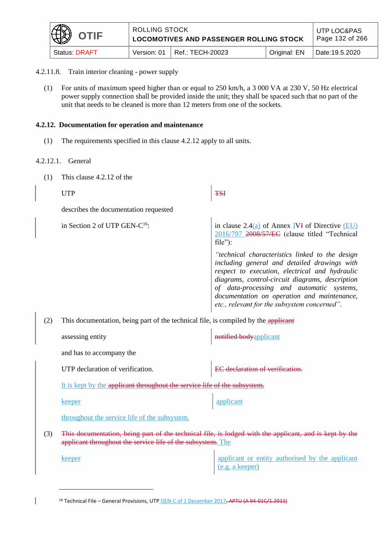
OTIF ROLLING STOCK
LOCOMOTIVES AND PASSENGER ROLLING STOCK
UTP LOC&PAS Page 132 of 266
Status: DRAFT Version: 01 Ref.: TECH-20023 Original: EN Date:19.5.2020
4.2.11.8. Train interior cleaning - power supply
(1) For units of maximum speed higher than or equal to 250 km/h, a 3 000 VA at 230 V, 50 Hz electrical
power supply connection shall be provided inside the unit; they shall be spaced such that no part of the
unit that needs to be cleaned is more than 12 meters from one of the sockets.
4.2.12. Documentation for operation and maintenance
(1) The requirements specified in this clause 4.2.12 apply to all units.
4.2.12.1. General
(1) This clause 4.2.12 of the
UTP TSI
describes the documentation requested
in Section 2 of UTP GEN-C16: in clause 2.4(a) of Annex IVI of Directive (EU)
2016/797 2008/57/EC (clause titled “Technical
file”):
“technical characteristics linked to the design
including general and detailed drawings with
respect to execution, electrical and hydraulic
diagrams, control-circuit diagrams, description
of data-processing and automatic systems,
documentation on operation and maintenance,
etc., relevant for the subsystem concerned”.
(2) This documentation, being part of the technical file, is compiled by the applicant
assessing entity notified bodyapplicant
and has to accompany the
UTP declaration of verification. EC declaration of verification.
It is kept by the applicant throughout the service life of the subsystem.
keeper applicant
throughout the service life of the subsystem.
(3) This documentation, being part of the technical file, is lodged with the applicant, and is kept by the
applicant throughout the service life of the subsystem. The
keeper applicant or entity authorised by the applicant
(e.g. a keeper)
16 Technical File – General Provisions, UTP GEN-C of 1 December 2017, APTU (A 94-01C/1.2011)
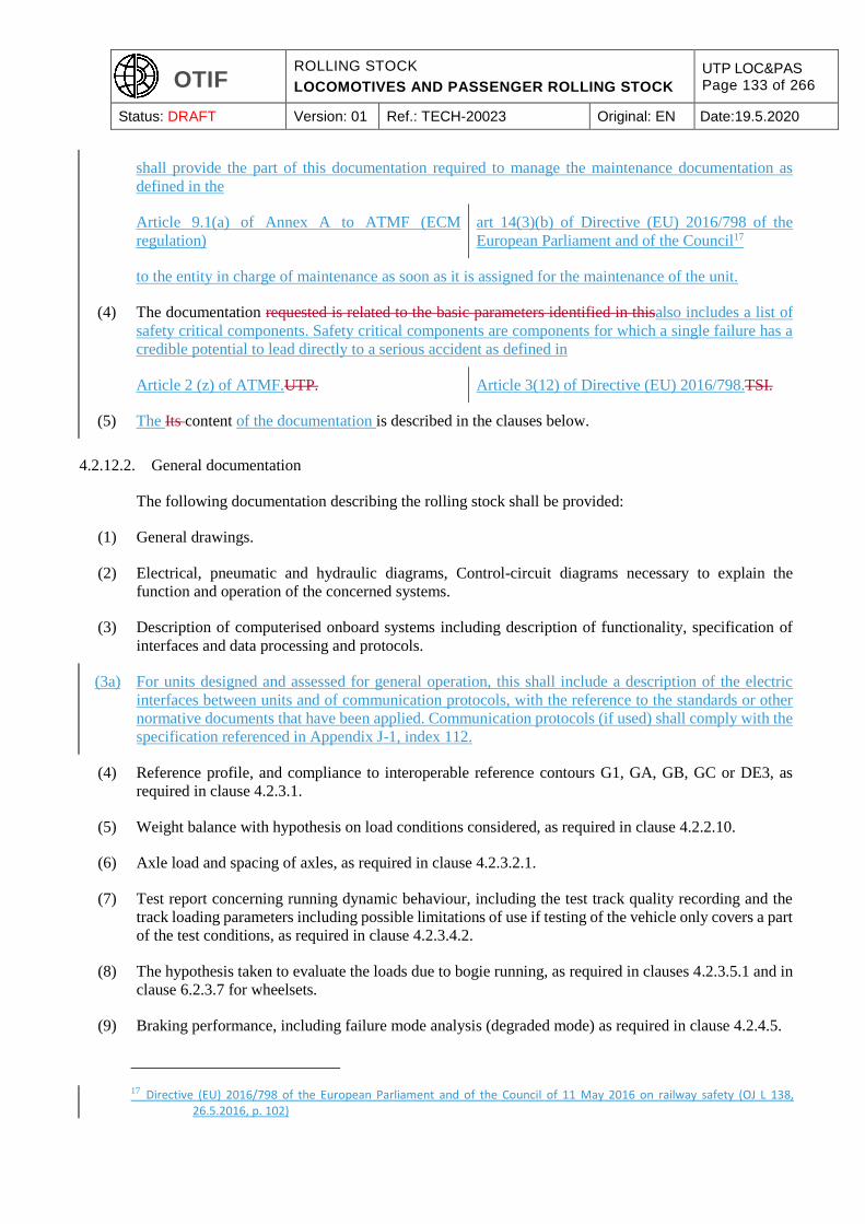
OTIF ROLLING STOCK
LOCOMOTIVES AND PASSENGER ROLLING STOCK
UTP LOC&PAS Page 133 of 266
Status: DRAFT Version: 01 Ref.: TECH-20023 Original: EN Date:19.5.2020
shall provide the part of this documentation required to manage the maintenance documentation as
defined in the
Article 9.1(a) of Annex A to ATMF (ECM
regulation)
art 14(3)(b) of Directive (EU) 2016/798 of the
European Parliament and of the Council17
to the entity in charge of maintenance as soon as it is assigned for the maintenance of the unit.
(4) The documentation requested is related to the basic parameters identified in thisalso includes a list of
safety critical components. Safety critical components are components for which a single failure has a
credible potential to lead directly to a serious accident as defined in
Article 2 (z) of ATMF.UTP. Article 3(12) of Directive (EU) 2016/798.TSI.
(5) The Its content of the documentation is described in the clauses below.
4.2.12.2. General documentation
The following documentation describing the rolling stock shall be provided:
(1) General drawings.
(2) Electrical, pneumatic and hydraulic diagrams, Control-circuit diagrams necessary to explain the
function and operation of the concerned systems.
(3) Description of computerised onboard systems including description of functionality, specification of
interfaces and data processing and protocols.
(3a) For units designed and assessed for general operation, this shall include a description of the electric
interfaces between units and of communication protocols, with the reference to the standards or other
normative documents that have been applied. Communication protocols (if used) shall comply with the
specification referenced in Appendix J-1, index 112.
(4) Reference profile, and compliance to interoperable reference contours G1, GA, GB, GC or DE3, as
required in clause 4.2.3.1.
(5) Weight balance with hypothesis on load conditions considered, as required in clause 4.2.2.10.
(6) Axle load and spacing of axles, as required in clause 4.2.3.2.1.
(7) Test report concerning running dynamic behaviour, including the test track quality recording and the
track loading parameters including possible limitations of use if testing of the vehicle only covers a part
of the test conditions, as required in clause 4.2.3.4.2.
(8) The hypothesis taken to evaluate the loads due to bogie running, as required in clauses 4.2.3.5.1 and in
clause 6.2.3.7 for wheelsets.
(9) Braking performance, including failure mode analysis (degraded mode) as required in clause 4.2.4.5.
17 Directive (EU) 2016/798 of the European Parliament and of the Council of 11 May 2016 on railway safety (OJ L 138, 26.5.2016, p. 102)
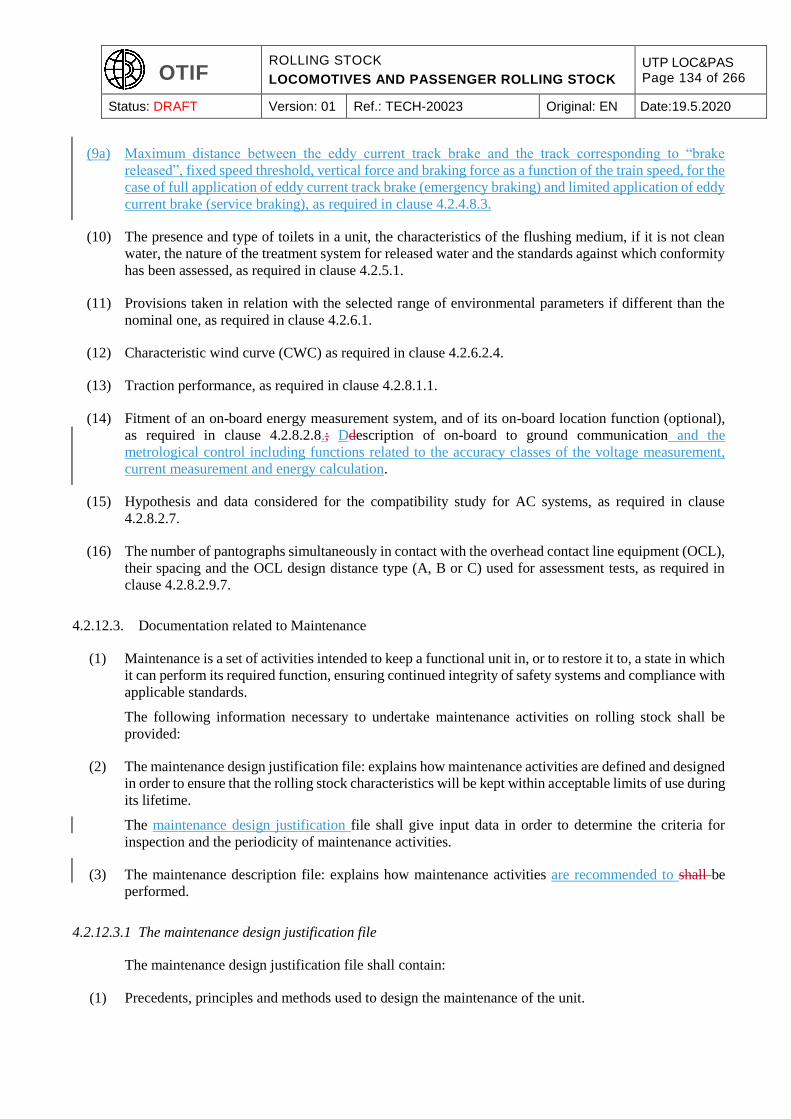
OTIF ROLLING STOCK
LOCOMOTIVES AND PASSENGER ROLLING STOCK
UTP LOC&PAS Page 134 of 266
Status: DRAFT Version: 01 Ref.: TECH-20023 Original: EN Date:19.5.2020
(9a) Maximum distance between the eddy current track brake and the track corresponding to “brake
released”, fixed speed threshold, vertical force and braking force as a function of the train speed, for the
case of full application of eddy current track brake (emergency braking) and limited application of eddy
current brake (service braking), as required in clause 4.2.4.8.3.
(10) The presence and type of toilets in a unit, the characteristics of the flushing medium, if it is not clean
water, the nature of the treatment system for released water and the standards against which conformity
has been assessed, as required in clause 4.2.5.1.
(11) Provisions taken in relation with the selected range of environmental parameters if different than the
nominal one, as required in clause 4.2.6.1.
(12) Characteristic wind curve (CWC) as required in clause 4.2.6.2.4.
(13) Traction performance, as required in clause 4.2.8.1.1.
(14) Fitment of an on-board energy measurement system, and of its on-board location function (optional),
as required in clause 4.2.8.2.8.; Ddescription of on-board to ground communication and the
metrological control including functions related to the accuracy classes of the voltage measurement,
current measurement and energy calculation.
(15) Hypothesis and data considered for the compatibility study for AC systems, as required in clause
4.2.8.2.7.
(16) The number of pantographs simultaneously in contact with the overhead contact line equipment (OCL),
their spacing and the OCL design distance type (A, B or C) used for assessment tests, as required in
clause 4.2.8.2.9.7.
4.2.12.3. Documentation related to Maintenance
(1) Maintenance is a set of activities intended to keep a functional unit in, or to restore it to, a state in which
it can perform its required function, ensuring continued integrity of safety systems and compliance with
applicable standards.
The following information necessary to undertake maintenance activities on rolling stock shall be
provided:
(2) The maintenance design justification file: explains how maintenance activities are defined and designed
in order to ensure that the rolling stock characteristics will be kept within acceptable limits of use during
its lifetime.
The maintenance design justification file shall give input data in order to determine the criteria for
inspection and the periodicity of maintenance activities.
(3) The maintenance description file: explains how maintenance activities are recommended to shall be
performed.
4.2.12.3.1 The maintenance design justification file
The maintenance design justification file shall contain:
(1) Precedents, principles and methods used to design the maintenance of the unit.
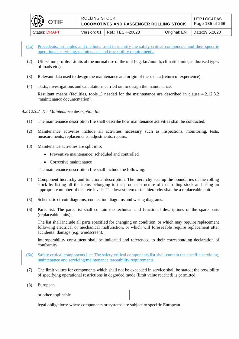
OTIF ROLLING STOCK
LOCOMOTIVES AND PASSENGER ROLLING STOCK
UTP LOC&PAS Page 135 of 266
Status: DRAFT Version: 01 Ref.: TECH-20023 Original: EN Date:19.5.2020
(1a) Precedents, principles and methods used to identify the safety critical components and their specific
operational, servicing, maintenance and traceability requirements.
(2) Utilisation profile: Limits of the normal use of the unit (e.g. km/month, climatic limits, authorised types
of loads etc.).
(3) Relevant data used to design the maintenance and origin of these data (return of experience).
(4) Tests, investigations and calculations carried out to design the maintenance.
Resultant means (facilities, tools...) needed for the maintenance are described in clause 4.2.12.3.2
“maintenance documentation”.
4.2.12.3.2 The Maintenance description file
(1) The maintenance description file shall describe how maintenance activities shall be conducted.
(2) Maintenance activities include all activities necessary such as inspections, monitoring, tests,
measurements, replacements, adjustments, repairs.
(3) Maintenance activities are split into:
Preventive maintenance; scheduled and controlled
Corrective maintenance
The maintenance description file shall include the following:
(4) Component hierarchy and functional description: The hierarchy sets up the boundaries of the rolling
stock by listing all the items belonging to the product structure of that rolling stock and using an
appropriate number of discrete levels. The lowest item of the hierarchy shall be a replaceable unit.
(5) Schematic circuit diagrams, connection diagrams and wiring diagrams.
(6) Parts list: The parts list shall contain the technical and functional descriptions of the spare parts
(replaceable units).
The list shall include all parts specified for changing on condition, or which may require replacement
following electrical or mechanical malfunction, or which will foreseeable require replacement after
accidental damage (e.g. windscreen).
Interoperability constituent shall be indicated and referenced to their corresponding declaration of
conformity.
(6a) Safety critical components list: The safety critical components list shall contain the specific servicing,
maintenance and servicing/maintenance traceability requirements.
(7) The limit values for components which shall not be exceeded in service shall be stated; the possibility
of specifying operational restrictions in degraded mode (limit value reached) is permitted.
(8) European
or other applicable
legal obligations: where components or systems are subject to specific European
OTIF ROLLING STOCK
LOCOMOTIVES AND PASSENGER ROLLING STOCK
UTP LOC&PAS Page 136 of 266
Status: DRAFT Version: 01 Ref.: TECH-20023 Original: EN Date:19.5.2020
or other applicable
legal obligations these obligations shall be listed.
(9) The structured set of tasks that include the activities, procedures, means proposed by the applicant to
carry out the maintenance task.
(10) The description of the maintenance activities.
The following aspects have to be documented (when they are specific to the application):
Disassembly/assembly instructions drawings necessary for correct assembly/disassembly of
replaceable parts
Maintenance criteria
Checks and tests
Tools and materials required to undertake the task (special tools)
Consumables required to undertake the task
Personal protective safety provision and equipment (special)
(11) Necessary tests and procedures to be undertaken after each maintenance operation before re-entry into
service of rolling stock.
(12) Troubleshooting (fault diagnosis) manuals or facilities for all reasonably foreseeable situations; this
includes functional and schematic diagrams of the systems or IT-based fault finding systems.
4.2.12.4. Operating documentation
The technical documentation necessary to operate the unit is composed of:
(1) A description of operation in normal mode, including the operational characteristics and limitations of
the unit (e.g. vehicle gauge, maximum design speed, axle loads, brake performance, type(s) and
operation of track gauge changeover facility(ies) the unit is compatible with...).
(2) A description of the various reasonably foreseeable degraded modes in case of safety significant failures
of equipment or functions described in this
UTP, TSI,
together with the related acceptable limits and operating conditions of the unit that could be
experienced.
(3) A description of the control and monitoring systems allowing the identification of safety significant
failures of equipment or functions described in this
UTP TSI
(e.g clause 4.2.4.9 related to the function “braking”).
(3a) Safety critical components list: The safety critical components list shall contain the specific operational
and traceability requirements.
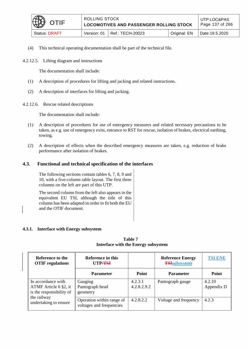
OTIF ROLLING STOCK
LOCOMOTIVES AND PASSENGER ROLLING STOCK
UTP LOC&PAS Page 137 of 266
Status: DRAFT Version: 01 Ref.: TECH-20023 Original: EN Date:19.5.2020
(4) This technical operating documentation shall be part of the technical file.
4.2.12.5. Lifting diagram and instructions
The documentation shall include:
(1) A description of procedures for lifting and jacking and related instructions.
(2) A description of interfaces for lifting and jacking.
4.2.12.6. Rescue related descriptions
The documentation shall include:
(1) A description of procedures for use of emergency measures and related necessary precautions to be
taken, as e.g. use of emergency exits, entrance to RST for rescue, isolation of brakes, electrical earthing,
towing.
(2) A description of effects when the described emergency measures are taken, e.g. reduction of brake
performance after isolation of brakes.
4.3. Functional and technical specification of the interfaces
The following sections contain tables 6, 7, 8, 9 and
10, with a five-column table layout. The first three
columns on the left are part of this UTP.
The second column from the left also appears in the
equivalent EU TSI, although the title of this
column has been adapted in order to fit both the EU
and the OTIF document.
4.3.1. Interface with Energy subsystem
Table 7
Interface with the Energy subsystem
Reference to the
OTIF regulations
Reference in this
UTP/TSI
Reference Energy
TSIsubsystem
TSI ENE
Parameter Point Parameter Point
In accordance with
ATMF Article 6 §2, it
is the responsibility of
the railway
undertaking to ensure
Gauging
Pantograph head
geometry
4.2.3.1
4.2.8.2.9.2
Pantograph gauge 4.2.10
Appendix D
Operation within range of
voltages and frequencies
4.2.8.2.2 Voltage and frequency 4.2.3
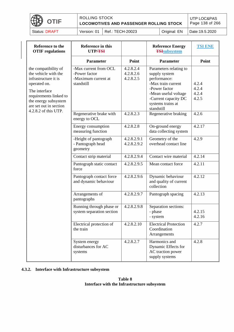
OTIF ROLLING STOCK
LOCOMOTIVES AND PASSENGER ROLLING STOCK
UTP LOC&PAS Page 138 of 266
Status: DRAFT Version: 01 Ref.: TECH-20023 Original: EN Date:19.5.2020
Reference to the
OTIF regulations
Reference in this
UTP/TSI
Reference Energy
TSIsubsystem
TSI ENE
Parameter Point Parameter Point
the compatibility of
the vehicle with the
infrastructure it is
operated on.
The interface
requirements linked to
the energy subsystem
are set out in section
4.2.8.2 of this UTP.
-Max current from OCL
-Power factor
-Maximum current at
standstill
4.2.8.2.4
4.2.8.2.6
4.2.8.2.5
Parameters relating to
supply system
performance:
-Max train current
-Power factor
-Mean useful voltage
-Current capacity DC
systems trains at
standstill
4.2.4
4.2.4
4.2.4
4.2.5
Regenerative brake with
energy to OCL
4.2.8.2.3 Regenerative braking 4.2.6
Energy consumption
measuring function
4.2.8.2.8 On-ground energy
data collecting system
4.2.17
-Height of pantograph
- Pantograph head
geometry
4.2.8.2.9.1
4.2.8.2.9.2
Geometry of the
overhead contact line
4.2.9
Contact strip material 4.2.8.2.9.4 Contact wire material 4.2.14
Pantograph static contact
force
4.2.8.2.9.5 Mean contact force 4.2.11
Pantograph contact force
and dynamic behaviour
4.2.8.2.9.6 Dynamic behaviour
and quality of current
collection
4.2.12
Arrangements of
pantographs
4.2.8.2.9.7 Pantograph spacing 4.2.13
Running through phase or
system separation section
4.2.8.2.9.8 Separation sections:
- phase
- system
4.2.15
4.2.16
Electrical protection of
the train
4.2.8.2.10 Electrical Protection
Coordination
Arrangements
4.2.7
System energy
disturbances for AC
systems
4.2.8.2.7 Harmonics and
Dynamic Effects for
AC traction power
supply systems
4.2.8
4.3.2. Interface with Infrastructure subsystem
Table 8
Interface with the Infrastructure subsystem

OTIF ROLLING STOCK
LOCOMOTIVES AND PASSENGER ROLLING STOCK
UTP LOC&PAS Page 139 of 266
Status: DRAFT Version: 01 Ref.: TECH-20023 Original: EN Date:19.5.2020
Reference to the
OTIF or national
regulations
Reference in this
UTP/TSI
Reference
Infrastructure
TSIUTP
Parameter Point Parameter Point
There are no
infrastructure
requirements in OTIF
regulations.
In accordance with
ATMF Article 6 § 2, it
is the responsibility of
the railway
undertaking to ensure
the compatibility of
the vehicle with the
infrastructure it is
operated on.
The track design and
layout are the
responsibility of the
Contracting State.
The interface
requirements at
vehicle level are set
out in section 4.2.3 of
this UTP.
Rolling stock kinematic
gauge
4.2.3.1 Structure gauge
Distance between track
centres
Minimum radius of
vertical curve
4.2.3.1
4.2.3.2
4.2.3.5
Axle load parameter 4.2.3.2.1 Track resistance to
vertical loads
Lateral track resistance
Resistance of new
bridges to traffic loads
Equivalent vertical
loading for new
earthworks and earth
pressure effects
Resistance of existing
bridges and earthworks
to traffic loads
4.2.6.1
4.2.6.3
4.2.7.1
4.2.7.2
4.2.7.4
Running dynamic
behaviour
4.2.3.4.2. Cant deficiency 4.2.4.3
Running dynamic limit
values for track loading
4.2.3.4.2.2 Track resistance to
vertical loads
Lateral track resistance
4.2.6.1
4.2.6.3
Equivalent conicity 4.2.3.4.3 Equivalent conicity 4.2.4.5
Geometrical
characteristics of wheelset
Geometrical
characteristics of wheels
Automatic Vvariable
gauge wheelsetssystems
4.2.3.5.2.1
4.2.3.5.2.2
4.2.3.5.2.3
Nominal track gauge
Rail head profile for
plain line
In service geometry of
switches and crossings
4.2.4.1
4.2.4.6
4.2.5.3
Minimum curve radius 4.2.3.6 Minimum radius of
horizontal curve
4.2.3.4
Maximum average
deceleration
4.2.4.5.1 Longitudinal track
resistance
Actions due to traction
and braking
4.2.6.2
4.2.7.1.5
Slipstream effects 4.2.6.2.1 Resistance of new
structures over or
adjacent to tracks
4.2.7.3
Head pressure pulse
Maximum pressure
variations in tunnels
4.2.6.2.2
4.2.6.2.3
Maximum pressure
variations in tunnels
Distance between track
centres
4.2.10.1
4.2.3.2
Crosswind 4.2.6.2.4 Effect of crosswinds 4.2.10.2
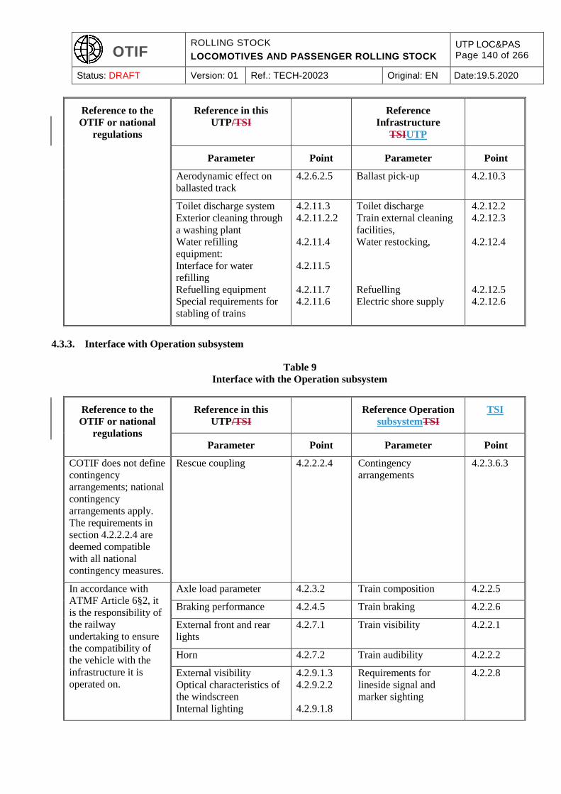
OTIF ROLLING STOCK
LOCOMOTIVES AND PASSENGER ROLLING STOCK
UTP LOC&PAS Page 140 of 266
Status: DRAFT Version: 01 Ref.: TECH-20023 Original: EN Date:19.5.2020
Reference to the
OTIF or national
regulations
Reference in this
UTP/TSI
Reference
Infrastructure
TSIUTP
Parameter Point Parameter Point
Aerodynamic effect on
ballasted track
4.2.6.2.5 Ballast pick-up 4.2.10.3
Toilet discharge system
Exterior cleaning through
a washing plant
Water refilling
equipment:
Interface for water
refilling
Refuelling equipment
Special requirements for
stabling of trains
4.2.11.3
4.2.11.2.2
4.2.11.4
4.2.11.5
4.2.11.7
4.2.11.6
Toilet discharge
Train external cleaning
facilities,
Water restocking,
Refuelling
Electric shore supply
4.2.12.2
4.2.12.3
4.2.12.4
4.2.12.5
4.2.12.6
4.3.3. Interface with Operation subsystem
Table 9
Interface with the Operation subsystem
Reference to the
OTIF or national
regulations
Reference in this
UTP/TSI
Reference Operation
subsystemTSI
TSI
Parameter Point Parameter Point
COTIF does not define
contingency
arrangements; national
contingency
arrangements apply.
The requirements in
section 4.2.2.2.4 are
deemed compatible
with all national
contingency measures.
Rescue coupling 4.2.2.2.4 Contingency
arrangements
4.2.3.6.3
In accordance with
ATMF Article 6§2, it
is the responsibility of
the railway
undertaking to ensure
the compatibility of
the vehicle with the
infrastructure it is
operated on.
Axle load parameter 4.2.3.2 Train composition 4.2.2.5
Braking performance 4.2.4.5 Train braking 4.2.2.6
External front and rear
lights
4.2.7.1 Train visibility 4.2.2.1
Horn 4.2.7.2 Train audibility 4.2.2.2
External visibility
Optical characteristics of
the windscreen
Internal lighting
4.2.9.1.3
4.2.9.2.2
4.2.9.1.8
Requirements for
lineside signal and
marker sighting
4.2.2.8

OTIF ROLLING STOCK
LOCOMOTIVES AND PASSENGER ROLLING STOCK
UTP LOC&PAS Page 141 of 266
Status: DRAFT Version: 01 Ref.: TECH-20023 Original: EN Date:19.5.2020
Reference to the
OTIF or national
regulations
Reference in this
UTP/TSI
Reference Operation
subsystemTSI
TSI
Parameter Point Parameter Point
Driver´s activity control
function
4.2.9.3.1 Driver vigilance 4.2.2.9
Recording device 4.2.9.6 Recording of
supervision data on-
board the train
4.2.3.5.2
4.3.4. Interface with the Control, command and signalling subsystem
Table 10
Interface with the Control, command and signaling subsystem
Reference to the
OTIF or national
regulations
Reference in this
UTP/TSI
Reference CCS
subsystemCCS TSI
CCS TSI
Parameter Point Parameter Point
In accordance with
ATMF Article 6§2, it
is the responsibility of
the railway
undertaking to ensure
the compatibility of
the vehicle with the
infrastructure it is
operated on.
The interfaces for
compatibility with
train detection
systems, control,
command and
signalling system are
set out in Appendix J-
2 index 1 of this UTP.
Rolling stock
characteristics compatible
with train detection
system based on track
circuits
4.2.3.3.1.1 Vehicle geometry
Vehicle design
Isolating emissions
EMC
Specificati
on
referenced
in Annex
A, Index 77
of TSI CCS
(Appendix
J-2 index 1
of this
UTP)
Rolling stock
characteristics compatible
with train detection
system based on axle
counters
4.2.3.3.1.2 Vehicle geometry
Wheel geometry
Vehicle design
EMC
Specificati
on
referenced
in Annex
A, Index 77
of TSI CCS
Rolling stock
characteristics compatible
with loop equipment
4.2.3.3.1.3 Vehicle design Specificati
on
referenced
in Annex
A, Index 77
of TSI CCS
Emergency braking
command
4.2.4.4.1 On-board ETCS
functionality
4.2.2
Emergency braking
performance
4.2.4.5.2 Guaranteed train
braking performance
and characteristics
4.2.2
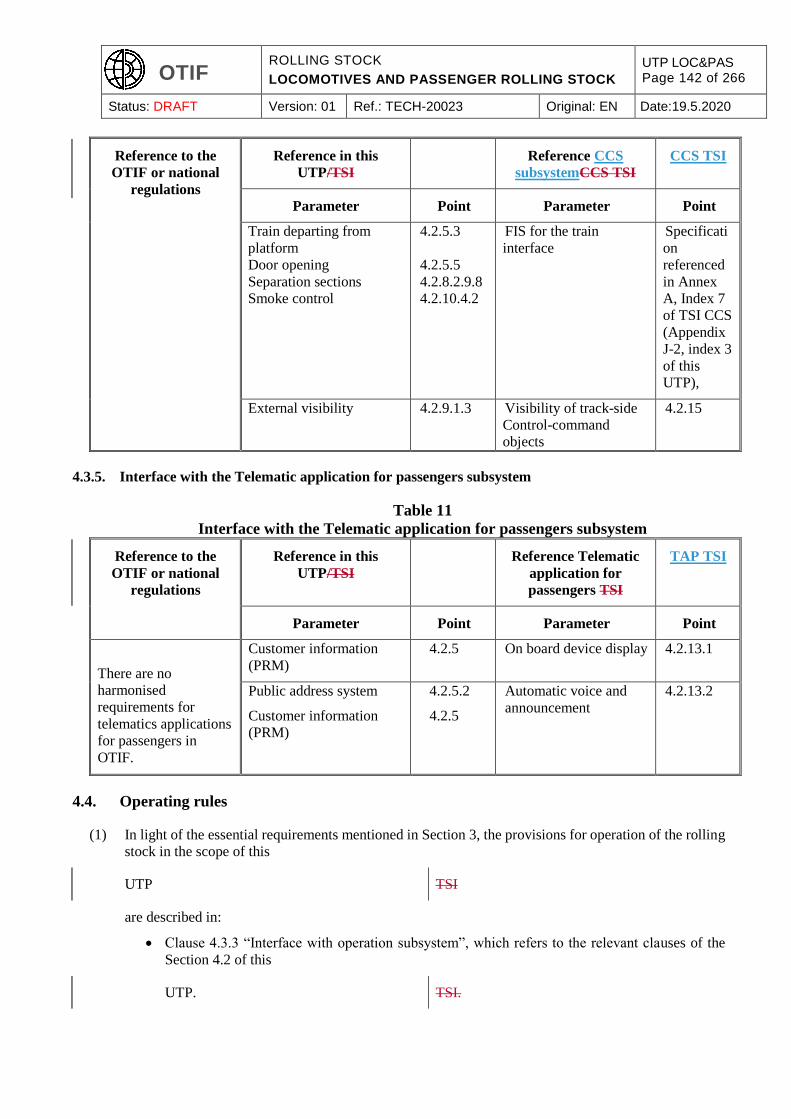
OTIF ROLLING STOCK
LOCOMOTIVES AND PASSENGER ROLLING STOCK
UTP LOC&PAS Page 142 of 266
Status: DRAFT Version: 01 Ref.: TECH-20023 Original: EN Date:19.5.2020
Reference to the
OTIF or national
regulations
Reference in this
UTP/TSI
Reference CCS
subsystemCCS TSI
CCS TSI
Parameter Point Parameter Point
Train departing from
platform
Door opening
Separation sections
Smoke control
4.2.5.3
4.2.5.5
4.2.8.2.9.8
4.2.10.4.2
FIS for the train
interface
Specificati
on
referenced
in Annex
A, Index 7
of TSI CCS
(Appendix
J-2, index 3
of this
UTP),
External visibility 4.2.9.1.3 Visibility of track-side
Control-command
objects
4.2.15
4.3.5. Interface with the Telematic application for passengers subsystem
Table 11
Interface with the Telematic application for passengers subsystem
Reference to the
OTIF or national
regulations
Reference in this
UTP/TSI
Reference Telematic
application for
passengers TSI
TAP TSI
Parameter Point Parameter Point
There are no
harmonised
requirements for
telematics applications
for passengers in
OTIF.
Customer information
(PRM)
4.2.5 On board device display 4.2.13.1
Public address system
Customer information
(PRM)
4.2.5.2
4.2.5
Automatic voice and
announcement
4.2.13.2
4.4. Operating rules
(1) In light of the essential requirements mentioned in Section 3, the provisions for operation of the rolling
stock in the scope of this
UTP TSI
are described in:
Clause 4.3.3 “Interface with operation subsystem”, which refers to the relevant clauses of the
Section 4.2 of this
UTP. TSI.
OTIF ROLLING STOCK
LOCOMOTIVES AND PASSENGER ROLLING STOCK
UTP LOC&PAS Page 143 of 266
Status: DRAFT Version: 01 Ref.: TECH-20023 Original: EN Date:19.5.2020
Clause 4.2.12 “Documentation for Operation and Maintenance”
(2) In accordance with Article 15a of ATMF Tthe
railway undertaking shall control the risks
associated with the use of the unit.
Operating rules covering the activities and
measures set out in Appendix Kof the railway
undertaking shall therefore be established to ensure
that the trains in which units are incorporated
comply with the essential requirements18.
Operating rules are developed under the railway
undertaking safety management system, with
consideration of these provisions.
(3) In particular, operating rules are necessary to ensure that a train stopped on a gradient as specified in
clauses 4.2.4.2.1 and 4.2.4.5.5 of this
UTP TSI
(requirements related to braking) will be immobilised.
The operating rules for use of the public address system, the passenger alarm, the emergency exits, the
operation of the access doors are elaborated with consideration of the relevant provisions of this
UTP TSI
and of the documentation for operation.
(3a) For the safety critical components, the specific operational and operational traceability requirements
are developed by the designers/manufacturers at design phase and through a collaboration between
designers/manufacturers and the concerned railway undertakings after vehicles have entered into
operation.
(4) The technical operating documentation described in clause 4.2.12.4 gives the rolling stock
characteristics to be considered in order to define the operating rules in degraded mode.
(5) Procedures for lifting and rescue are established (including the method and the means of recovering a
derailed train or a train that is unable to move normally) with consideration of:
the provisions for lifting and jacking described in clauses 4.2.2.6 and 4.2.12.5 of this
UTP; TSI;
the provisions related to the braking system for rescue described in clauses 4.2.4.10 and 4.2.12.6
of this
UTP. TSI.
(6) The safety rules for trackside workers or passengers on platforms are developed by the entity(ies)
responsible for fixed installations with consideration of the relevant provisions of this
UTP TSI
18 Unlike EU law, where the RU is responsible, OTIF law does not specify who should establish these operating rules.
OTIF ROLLING STOCK
LOCOMOTIVES AND PASSENGER ROLLING STOCK
UTP LOC&PAS Page 144 of 266
Status: DRAFT Version: 01 Ref.: TECH-20023 Original: EN Date:19.5.2020
and of the technical documentation (e.g. impact of speed).
4.5. Maintenance rules
(1) In light of the essential requirements mentioned in Section 3, the provisions for maintenance of the
rolling stock in the scope of this
UTP: TSI:
Clause 4.2.11 “Servicing”
Clause 4.2.12 “Documentation for Operation and Maintenance”.
(2) Other provisions in the section 4.2 (clauses 4.2.3.4 and 4.2.3.5) specify for particular characteristics the
limit values that have to be verified during maintenance activities.
(2a) The safety critical components and their specific servicing, maintenance and maintenance traceability
requirements are identified by the designers/manufacturers at design phase and through a collaboration
between designers/manufacturers and the concerned entities in charge of maintenance after vehicles
have entered into operation.
(3) From the information mentioned above and provided in the clause 4.2, the appropriate tolerances and
intervals to ensure compliance with the essential requirements throughout the lifetime of the rolling
stock are defined at maintenance operational level by and under the sole responsibility of entities in
charge of maintenance (not in the scope of the assessment against this
UTP); TSI);
this activity includes:
The definition of the in-service values where they are not specified in this
UTP, TSI,
or where operating conditions allow the use of different in-service limit values than those
specified in this
UTP. TSI.
The justification of the in-service values, by providing the equivalent information to those
required in clause 4.2.12.3.1 “The maintenance design justification file”.
(4) On the basis of the information mentioned above in this clause, a maintenance plan is defined at
maintenance operational level by and under the sole responsibility of the entities in charge of
maintenance (not in the scope of the assessment against this
UTP), TSI),
consisting in a structured set of maintenance tasks that include the activities, tests and procedures,
means, maintenance criteria, periodicity, working time required to carry out the maintenance tasks.
(5) For on-board software, the designer/manufacturer shall specify, for any on-board software modification,
all maintenance requirements and procedures (including health monitoring, diagnosis of events, test

OTIF ROLLING STOCK
LOCOMOTIVES AND PASSENGER ROLLING STOCK
UTP LOC&PAS Page 145 of 266
Status: DRAFT Version: 01 Ref.: TECH-20023 Original: EN Date:19.5.2020
methods and tools and also the required professional competence) necessary for achieving essential
requirements and values quoted in the mandatory requirements of this UTP throughout the life-cycle
(Installation, normal operation, failures, repair work, checking and maintenance, decommissioning,
etc.).
4.6. Professional competencies
(1) The professional competencies of staff required for
the operational activities relating to train
composition and the use of vehicles within their
limits and conditions of use are set out in section
4.4 Operating Rules of this UTP19 and the UTP on
train composition and route compatibility checks.
the operation of the rolling stock in the scope of
this TSI are not set out in this TSI.
They are partly covered by
(2) Appendix K Additional rules may apply in each
Contracting State.
They are partly covered by the OPE TSI and
Directive 2007/59/EC20
, or according to the regulations in the Contracting
State that prescribe specifications for train drivers
operating locomotives and trains.
and Directive 2007/59/EC21
4.7. Health and safety conditions
(1) The provisions for health and safety of staff required for the operation and maintenance of the rolling
stock in the scope of this
UTP TSI
are covered by the essential requirements No. 1.1, 1.3, 2.5.1, 2.6.1
(as numbered in a UTP GEN-A); (as numbered in Directive (EU)
2016/7972008/57/EC);
the table in section 3.2 mentions the technical clauses of this
UTP TSI
in relation to these essential requirements.
(2) In particular, the following provisions of section 4.2 specify provisions for health and safety of staff:
Clause 4.2.2.2.5: Staff access for coupling and uncoupling.
19 Professional competencies of staff required for the maintenance of units are not covered by this UTP, because they are covered by the regulation for the Entity in Charge of Maintenance.
20 OJ L 315, 03.12.2007, p.51 21 OJ L 315, 03.12.2007, p.51
OTIF ROLLING STOCK
LOCOMOTIVES AND PASSENGER ROLLING STOCK
UTP LOC&PAS Page 146 of 266
Status: DRAFT Version: 01 Ref.: TECH-20023 Original: EN Date:19.5.2020
Clause 4.2.2.5: Passive safety.
Clause 4.2.2.8: Staff and freight access doors.
Clause 4.2.6.2.1: Slipstream effects on workers at trackside.
Clause 4.2.7.2.2: Warning horn sound pressure.
Clause 4.2.8.4: Protection against electrical hazards.
Clause 4.2.9: Driver’s cab.
Clause 4.2.10: Fire safety and evacuation.
Additional rules may apply in each Contracting
State.
4.8. Register of authorised types of vehicles European register of authorised types of
vehicles
(1) (reserved) The characteristics of the rolling stock that must
be recorded in the “European register of
authorised types of vehicles” are listed in
Commission Implementing Decision of 4 October
2011 on the European register of authorised types
of railway vehicles22.
(2) In accordance with
UTP GEN-C and the OTIF Uniform format of
certificates,
Annex II of this decision on the European register
and with point (a) of Article 348(32a) of Directive
(EU) 2016/7972008/57/EC,
the values to be recorded for the parameters related to the technical characteristics of the rolling stock
shall be those of the technical documentation accompanying the type examination certificate. Therefore,
this
UTP TSI
requires that the relevant characteristics are recorded in the technical documentation defined in the
clause 4.2.12.
(3) In accordance with Article 5 of the Decision
referred to in the above point (1) of this clause 4.8,
its application guide includes for each parameter
a reference to the clauses of the technical
specifications for interoperability that state the
requirements for this parameter.
22 Implementing Decision 2011/665/EU (notified under document C (2011) 6974), OJ L 264, 08.10.2011, p.32
OTIF ROLLING STOCK
LOCOMOTIVES AND PASSENGER ROLLING STOCK
UTP LOC&PAS Page 147 of 266
Status: DRAFT Version: 01 Ref.: TECH-20023 Original: EN Date:19.5.2020
4.9. Route compatibility checks before the use of authorised vehicles
The parameters of the subsystem “rolling stock — locomotives and passenger rolling stock” to be used
by the railway undertaking, for the purpose of route compatibility check, are described in
UTP TCRC23 Appendix D1 of Commission Implementing
Regulation (EU) 2019/77324.
5. INTEROPERABILITY CONSTITUENTS
5.1. Definition
(1) Elements of Construction or “interoperability
constituents” (ICs), are defined in Article 2(g) of
ATMF.
According to Article 2 (f7) of Directive (EU)
2016/7972008/57/EC, the interoperability
constituents are “any elementary component,
group of components, subassembly or complete
assembly of equipment incorporated or intended
to be incorporated into a subsystem upon which
the interoperability of the rail system depends
directly or indirectly.”
(2) The concept of a “constituent” covers both tangible objects and intangible objects such as software.
(3) ICs Interoperability constituents (IC)
described in section 5.3 below are constituents:
Whose specification refers to a requirement defined in section 4.2 of this
UTP. TSI.
The reference to the relevant clause of the section 4.2 is given in section 5.3; it defines how the
interoperability of the rail system depends on the particular constituent.
An IC shall comply with the technical
specifications of this chapter whether it is
assessed separately as an IC or is assessed
as an integrated part of a subsystem.
Assessment of IC separate from the
subsystem is not mandatory in the COTIF
regulations, but Contracting States or
regional organisations25 may require
mandatory separate assessment according to
the specification in sections 5.3 and 6.1 of
23 UTP TCRC on Train composition and Route Compatibility Checks 24 Commission Implementing Regulation (EU) 2019/773 of 16 May 2019 on the technical specification for interoperability
relating to the operation and traffic management subsystem of the rail system within the European Union and repealing Decision 2012/757/EU (OJ L 139 I, 27.5.2019, p. 5).
25 In particular, compliance with EU law must be ensured when placing an IC on the market in the European Union.

OTIF ROLLING STOCK
LOCOMOTIVES AND PASSENGER ROLLING STOCK
UTP LOC&PAS Page 148 of 266
Status: DRAFT Version: 01 Ref.: TECH-20023 Original: EN Date:19.5.2020
this UTP. This possibility is without
prejudice to section 6.326.
Separate assessment of an IC:
If the IC is in conformity with this UTP, as
evidenced by the manufacturer in the form
of a declaration of conformity or suitability
for use according to section 6.1 of this UTP
and chapter 2 of UTP GEN-D, the IC may
be used in accordance with its defined area
of use, in accordance with section 5.3, in all
Contracting States.
Assessment of an IC integrated into a
vehicle:
If the IC is assessed as a part of the
subsystem, the assessment procedures for
subsystems apply. The requirements are
identical to those if the IC were to be
assessed separately, i.e. those set out in
sections 5.3 and 6.1.
When a requirement is
identified in section 5.3 as being
assessed at IC level, an assessment for the same requirement at sub-system level is not required.
Whose specification may need additional requirements, such as interface requirements; these
additional requirements are also specified in section 5.3.
And whose assessment procedure, independently of the related subsystem is described in section
6.1.
(4) The area of use of an interoperability constituent shall be stated and demonstrated as described for each
of them in section 5.3.
5.2. Innovative solution
(1) Innovative As stated in article 10, innovative
solutions may require new specification and / or new assessment methods. Such specifications and
assessment methods shall be developed by the process described in clause 6.1.5 whenever an innovative
solution is envisaged for an IC.
5.3. Interoperability constituents specification
The Interoperability constituents are listed and specified below:
26 6.3 permits, during a transitional period, the use of ICs produced before the entry into force of this UTP.
OTIF ROLLING STOCK
LOCOMOTIVES AND PASSENGER ROLLING STOCK
UTP LOC&PAS Page 149 of 266
Status: DRAFT Version: 01 Ref.: TECH-20023 Original: EN Date:19.5.2020
5.3.1. Automatic centre buffer coupler
An automatic coupler shall be designed and assessed for an area of use defined by:
(1) The type of end coupling (mechanical and pneumatic interface of the head);
The ‘type 10’ automatic coupler shall be compliant with the specification referenced in Appendix J-1,
index 66.
Note: other types of automatic couplers than type 10 are not considered as an IC (specification not
publicly available).
(2) The tensile and compressive forces it is capable of withstanding;
(3) These characteristics shall be assessed at IC level.
5.3.2. Manual end coupling
A manual end coupling shall be designed and assessed for an area of use defined by:
(1) The type of end coupling (mechanical interface).
The ‘UIC type’ shall be composed of buffer, draw gear and screw coupling system complying with the
requirements of parts related to passenger coaches of the specification referenced in Appendix J-1, index
67 and the specification referenced in Appendix J-1, index 68; units other than coaches with manual
coupling systems shall be fitted with a buffer, draw gear and screw coupling system complying with
the relevant parts of the specification referenced in Appendix J-1, index 67 and the specification
referenced in Appendix J-1, index 68 respectively.
Note: other types of manual end coupling are not considered as an IC (specification not publicly
available).
(2) The tensile and compressive forces it is capable of withstanding.
(3) These characteristics shall be assessed at IC level.
5.3.3. Rescue couplers
A rescue coupler shall be designed and assessed for an area of use defined by:
(1) The type of end coupling it is capable of being interfaced with;
The rescue coupler to be interfaced with the ‘type 10’ automatic coupler shall be compliant with the
specification referenced in Appendix J-1, index 69.
Note: other types of rescue coupler are not considered as an IC (specification not publicly available)
(2) The tensile and compressive forces it is capable of withstanding.
(3) The way it is intended to be installed on the rescuing unit.
(4) These characteristics and the requirements expressed in clause 4.2.2.2.4 of this
UTP TSI
OTIF ROLLING STOCK
LOCOMOTIVES AND PASSENGER ROLLING STOCK
UTP LOC&PAS Page 150 of 266
Status: DRAFT Version: 01 Ref.: TECH-20023 Original: EN Date:19.5.2020
shall be assessed at IC level.
5.3.4. Wheels
A wheel shall be designed and assessed for an area of use defined by:
(1) Geometrical characteristics: nominal tread diameter.
(2) Mechanical characteristics: maximum vertical static force and maximum speed.
(3) Thermo mechanical characteristics: maximum braking energy.
(4) A wheel shall comply with the requirements on geometrical, mechanical and thermo mechanical
characteristics defined in clause 4.2.3.5.2.2; these requirements shall be assessed at IC level.
5.3.4a Automatic variable gauge systems
(1) An IC “automatic variable gauge system” shall be designed and assessed for an area of use defined by:
The track gauges the system is designed for.
The range of maximum static axle loads (corresponding to design mass under normal
payload as defined in clause 4.2.2.10 of this UTP).
The range of nominal wheel tread diameters.
The maximum design speed of the unit.
The type(s) of track gauge changeover facility(ies) the system is designed for, including
the nominal speed through the track gauge changeover facility(ies) and the maximum
axial forces during the automatic gauge changeover process.
(2) An automatic variable gauge system shall comply with the requirements set out in clause
4.2.3.5.2.3; these requirements shall be assessed at IC level as set out in clause 6.1.3.1a.
5.3.5. WSP (wheel slide protection system)
A IC “WSP system” shall be designed and assessed for an area of use defined by:
(1) A brake system of pneumatic type.
Note: the WSP is not considered as an IC for other types of brake system such as hydraulic, dynamic
and mixed braking systems, and this clause does not apply in that case.
(2) The maximum operating speed.
(3) A WSP system shall comply with the requirements related to the wheel slide protection system
performance expressed in clause 4.2.4.6.2 of this
UTP. TSI.
The wheel rotation monitoring system may be included as an option.
OTIF ROLLING STOCK
LOCOMOTIVES AND PASSENGER ROLLING STOCK
UTP LOC&PAS Page 151 of 266
Status: DRAFT Version: 01 Ref.: TECH-20023 Original: EN Date:19.5.2020
5.3.6. Head lamps
(1) A head lamp is designed and assessed without any limitation concerning its area of use.
(2) A head lamp shall comply with requirements concerning the colour and the luminous intensity defined
in clause 4.2.7.1.1. These requirements shall be assessed at IC level.
5.3.7. Marker lamps
(1) A marker lamp is designed and assessed without any limitation concerning its area of use.
(2) A marker lamp shall comply with requirements concerning the colour and the luminous intensity
defined in clause 4.2.7.1.2. These requirements shall be assessed at IC level.
5.3.8. Tail lamps
(1) A tail lamp shall be designed and assessed for an area of use: fixed lamp or portable lamp.
(2) A tail lamp shall comply with the requirements concerning the colour and the luminous intensity defined
in clause 4.2.7.1.3. These requirements shall be assessed at IC level.
(3) For portable tail lamps, the interface for attachment on the vehicle shall be in accordance with the
Appendix E of the
UTP TSI
“freight wagons”.
5.3.9. Horns
(1) A horn shall be is designed and assessed for an area of use defined by its sound pressure level on a
reference vehicle (or reference integration); this characteristic may be affected by the integration of the
horn in a particular vehicle.
(2) A horn shall comply with the requirements concerning the soundings of signals defined in clause
4.2.7.2.1. These requirements shall be assessed at IC level.
5.3.10. Pantograph
A pantograph shall be designed and assessed for an area of use defined by:
(1) The type of voltage system(s), as defined in clause 4.2.8.2.1.
In case it is designed for different voltage systems, the various sets of requirements shall be taken into
account.
(2) One of the 3 pantograph head geometries specified in clause 4.2.8.2.9.2.
(3) The current capacity, as defined in clause 4.2.8.2.4.
(4) The maximum current at standstill per contact wire of the overhead contact line for DC systems.
OTIF ROLLING STOCK
LOCOMOTIVES AND PASSENGER ROLLING STOCK
UTP LOC&PAS Page 152 of 266
Status: DRAFT Version: 01 Ref.: TECH-20023 Original: EN Date:19.5.2020
Note: the maximum current at standstill, as defined in clause 4.2.8.2.5., shall be compatible with the
value above, considering the characteristics of the overhead contact line (1 or 2 contact wires).
(5) The maximum operating speed: assessment of the maximum operating speed shall be performed as
defined in clause 4.2.8.2.9.6.
(6) Range of height for dynamic behaviour: standard, and/or for 1520 mm or 1524 mm track gauge systems.
(7) The requirements listed above shall be assessed at IC level.
(8) The working range in height of pantograph specified in clause 4.2.8.2.9.1.2, the pantograph head
geometry specified in clause 4.2.8.2.9.2, the pantograph current capacity specified in clause 4.2.8.2.9.3,
the pantograph static contact force specified in clause 4.2.8.2.9.5 and the dynamic behaviour of the
pantograph itself specified in clause 4.2.8.2.9.6 shall also be assessed at IC level.
5.3.11. Contact strips
(1) The contact strips are the replaceable parts of the pantograph head which are in contact with the contact
wire.
Contacts strips shall be designed and assessed for an area of use defined by:
(2) Their geometry, as defined in clause 4.2.8.2.9.4.1.
(3) The material of the contact strips, as defined in clause 4.2.8.2.9.4.2.
(4) The type of voltage system(s), as defined in clause 4.2.8.2.1.
(5) The current capacity, as defined in clause 4.2.8.2.4.
(6) The maximum current at standstill for DC systems, as defined in clause 4.2.8.2.5.
(7) The requirements listed above shall be assessed at IC level.
5.3.12. Main circuit breaker
A main circuit breaker shall be designed and assessed for an area of use defined by:
(1) The type of voltage system(s), as defined in clause 4.2.8.2.1.
(2) The current capacity, as defined in clause 4.2.8.2.4 (maximum current).
(3) The requirements listed above shall be assessed at IC level.
(4) The tripping shall be as specified in the specification referenced in Appendix J-1, index 70 (see clause
4.2.8.2.10 of this
UTP).; TSI); it shall be assessed at the IC level.
OTIF ROLLING STOCK
LOCOMOTIVES AND PASSENGER ROLLING STOCK
UTP LOC&PAS Page 153 of 266
Status: DRAFT Version: 01 Ref.: TECH-20023 Original: EN Date:19.5.2020
5.3.13. Driver’s seat
(1) A driver’s seat shall be is designed and assessed for an area of use defined by the range of possible
adjustments in height and longitudinal position.
(2) A driver’s seat shall comply to the requirements specified at component level in the clause 4.2.9.1.5.
These requirements shall be assessed at IC level.
5.3.14. Toilet discharge connection
(1) A toilet discharge connection is designed and assessed without any limitation concerning its area of use.
(2) A toilet discharge connection shall comply with requirements concerning the dimensions as defined in
clause 4.2.11.3. These requirements shall be assessed at IC level.
5.3.15. Inlet connection for water tanks
(1) A inlet connection for water tanks is designed and assessed without any limitation concerning its area
of use.
(2) A inlet connection for water tanks shall comply with requirements concerning the dimensions as defined
in clause 4.2.11.5. These requirements shall be assessed at IC level.
6. ASSESSMENT OF CONFORMITY OR SUITABILITY FOR USE
AND 'EC' VERIFICATION
(1) Modules for the
assessment procedures for the verification of
elements of construction are described in the UTP
GEN-D.
procedures for assessment of conformity,
suitability for use and EC verification are
described in the Commission Decision
2010/713/EU.
6.1. Elements of construction (IC) Interoperability constituent (IC)
6.1.1. Conformity assessment
(1) In accordance with UTP GEN-D, Contracting
States may require the mandatory separate
assessment of ICs. If not required by the
Contracting State, separate assessment of ICs may
be carried out on a voluntary basis.
In the case of separate IC assessment, the
manufacturer bears full responsibility for the UTP
compliance of the product within its specified area
of use.
An EC declaration of conformity or suitability for
use, in accordance with Article 103(1) and Annex
IV of Directive (EU) 2016/7972008/57/EC, shall
be drawn up by the manufacturer or his authorised
representative established in the Union before
placing a interoperability constituent on the
market.
OTIF ROLLING STOCK
LOCOMOTIVES AND PASSENGER ROLLING STOCK
UTP LOC&PAS Page 154 of 266
Status: DRAFT Version: 01 Ref.: TECH-20023 Original: EN Date:19.5.2020
(2) In case of separate IC assessment, the assessment The assessment of conformity or suitability for
use of an interoperability constituent
shall be performed according to the prescribed module(s) of that particular constituent specified in
clause 6.1.2 of this
UTP. TSI.
(3) In case of a specific case applicable to a component defined as interoperability constituent in section
5.3 of this UTP, the corresponding requirement can be part of the verification at interoperability
constituent level only in the case where the component remains compliant to the chapters 4 and 5 of
this UTP, and where the specific case does not refer to a national rule (i.e. additional requirement
compatible with the core UTP and fully specified in the UTP).
In other cases, the verification shall be made at subsystem level; when a national rule applies to a
component, the concerned Contracting State may define relevant applicable conformity assessment
procedures.
6.1.2. Application of modules
Assessment procedures for the verification of
elements of construction
Modules for EC certification of conformity of
interoperability constituents
Module CA Internal production control
Module CA1 Internal production control plus product verification by individual
examination
Module CA2 Internal production control plus product verification at random
intervals
Module CB Type examination EC-Type examination
Module CC Conformity to type based on internal production control
Module CD Conformity to type based on quality management system of the
production process
Module CF Conformity to type based on product verification
Module CH Conformity based on full quality management system
Module CH1 Conformity based on full quality management system plus design
examination
Module CV Type validation by in service experience (Suitability for use)
(1) In the case of separate IC assessment, the
manufacturer
The manufacturer or his authorised representative
established within the European Union
shall choose one of the modules or module combinations indicated in the following table for the
constituent to be assessed:

OTIF ROLLING STOCK
LOCOMOTIVES AND PASSENGER ROLLING STOCK
UTP LOC&PAS Page 155 of 266
Status: DRAFT Version: 01 Ref.: TECH-20023 Original: EN Date:19.5.2020
Point Constituents to be
assessed
Module
CA
Module
CA1or
CA227
Module
CB+CC
Module
CB+CD
Module
CB+CF
Module
CH
Module
CH1
5.3.1 Automatic centre
buffer coupler X(*) X X X(*) X
5.3.2 Manual end coupling X(*) X X X(*) X
5.3.3 Towing coupler for
rescue X(*) X X X(*) X
5.3.4 Wheel X(*) X X X(*) X
5.3.4a Automatic variable
gauge systems X(*) X X X(*) X
5.3.5 Wheel slide
protection system X(*) X X X(*) X
5.3.6 Head lamp X(*) X X X(*) X
5.3.7 Marker lamp X(*) X X X(*) X
5.3.8 Tail lamp X(*) X X X(*) X
5.3.9 Horns X(*) X X X(*) X
5.3.10 Pantograph X(*) X X X(*) X
5.3.11 Pantograph contact
strips X(*) X X X(*) X
5.3.12 Main circuit breaker X(*) X X X(*) X
5.3.13 Driver’s seat X(*) X X X(*) X
5.3.14 Toilet discharge
connection X X X
5.3.15 Inlet connection for
water tanks X X X
(*) Modules CA1, CA2 or CH may be used only in the
case of products manufactured according to a design
developed and already used to place products on the
market before the entry into force of relevant TSI
27 Modules CA1, CA2 or CH may be used only in the case of products manufactured according to a design developed and already used to place products on the market before the entry into force of relevant UTP applicable to those products, provided that the manufacturer demonstrates to the assessing entity that design review and type examination were performed for previous applications under comparable conditions, and are in conformity with the requirements of this UTP; this demonstration shall be documented, and is considered as providing the same level of proof as module CB or design examination according to module CH1.
OTIF ROLLING STOCK
LOCOMOTIVES AND PASSENGER ROLLING STOCK
UTP LOC&PAS Page 156 of 266
Status: DRAFT Version: 01 Ref.: TECH-20023 Original: EN Date:19.5.2020
applicable to those products, provided that the
manufacturer demonstrates to the notified body that
design review and type examination were performed
for previous applications under comparable conditions,
and are in conformity with the requirements of this
TSI; this demonstration shall be documented, and is
considered as providing the same level of proof as
module CB or design examination according to module
CH1.
(2) Where a particular procedure shall be used for the assessment, in addition to the requirements expressed
in the clause 4.2 of this
UTP, TSI,
this is specified in the clause 6.1.3 below.
6.1.3. Particular assessment procedures for interoperability constituents
6.1.3.1. Wheels (clause 5.3.4)
(1) The mechanical characteristics of the wheel shall be proven by mechanical strength calculations, taking
into account three load cases: straight track (centred wheelset), curve (flange pressed against the rail),
and negotiating of points and crossings (inside surface of flange applied to the rail), as specified in the
specification referenced in Appendix J-1, index 71, clauses 7.2.1 and 7.2.2.
(2) For forged and rolled wheels, the decision criteria are defined in the specification referenced in
Appendix J-1, index 71, clause 7.2.3; where the calculation show values beyond the decision criteria, a
bench test according to the specification referenced in Appendix J-1, index 71, clause 7.3 is required to
be performed to demonstrate compliance.
(3) Other types of wheels are permitted for vehicles restricted to national use. In that case the decision
criteria and the fatigue stress criteria shall be specified in national rules. Those national rules shall be
notified by Member States.
(4) The assumption of the load conditions for the maximum vertical static force shall be explicitly stated in
the technical documentation as set out in clause 4.2.12 of this
UTP. TSI.
Thermo-mechanical behaviour:
(5) If the wheel is used to brake a unit with blocks acting on the wheel running surface, the wheel shall be
thermo mechanically proven by taking into account the maximum braking energy foreseen. The wheel
shall be subject to a conformity assessment in accordance with the specification referenced in Appendix
J-1, index 71, clause 6 in order to check that the lateral displacement of the rim during braking and the
residual stress are within tolerance limits specified utilising the decision criteria specified.
Verification of the wheels:
(6) A verification procedure shall exist to ensure at the production phase that no defects may detrimentally
affect safety due to any change in the mechanical characteristics of the wheels.
OTIF ROLLING STOCK
LOCOMOTIVES AND PASSENGER ROLLING STOCK
UTP LOC&PAS Page 157 of 266
Status: DRAFT Version: 01 Ref.: TECH-20023 Original: EN Date:19.5.2020
The tensile strength of the material in the wheel, the hardness of the running surface, the fracture
toughness, the resistance to impact, the material characteristics and the material cleanliness shall be
verified.
The verification procedure shall specify the batch sampling used for each characteristic to be verified.
(7) Other conformity assessment method for wheels is allowed under the same conditions as for wheelsets;
these conditions are described in clause 6.2.3.7.
(8) In case of innovative design for which the manufacturer has no sufficient return of experience, the wheel
should be subject to an assessment of suitability for use (module CV; see also clause 6.1.6).
6.1.3.1a Automatic variable gauge system (clause 5.3.4a)
(1) The assessment procedure shall be based on a validation plan covering all aspects mentioned in clauses
4.2.3.5.3 and 5.3.4a.
(2) The validation plan shall be consistent with the safety analysis required in clause 4.2.3.5.3 and shall
define the assessment needed in all the following different phases:
Design review.
Static tests (bench tests and integration in the running gear/unit tests).
Test on track gauge changeover facility(ies), representative of in-service conditions.
On-track tests, representative of in-service conditions.
(3) Regarding the demonstration of compliance to points (5) of clause 4.2.3.5.3, the assumptions considered
for the safety analysis related to the vehicle the system is intended to be integrated in, and related to the
mission profile of that vehicle, shall be clearly documented.
(4) The automatic variable gauge system may be subject to an assessment of suitability for use (module
CV; see also clause 6.1.6).
(5) The certificate delivered by the Assessing entity in charge of the conformity assessment shall include
both the conditions for use as per clause 5.3.4a (1) and the type(s) and operating conditions of the track
gauge changeover facility(ies) the automatic variable gauge system has been assessed for.
6.1.3.2. Wheel slide protection system (clause 5.3.5)
(1) The wheel slide protection system shall be verified according to the methodology defined in the
specification referenced in Appendix J-1, index 72, clause 5; when reference is made to the clause 6.2
of the same specification “overview of required test programmes”, only the clause 6.2.3 applies, and it
applies to all WSP systems.
(2) In case of innovative design for which the manufacturer has no sufficient return of experience, the wheel
slide protection system should be subject to an assessment of suitability for use (module CV; see also
clause 6.1.6).
OTIF ROLLING STOCK
LOCOMOTIVES AND PASSENGER ROLLING STOCK
UTP LOC&PAS Page 158 of 266
Status: DRAFT Version: 01 Ref.: TECH-20023 Original: EN Date:19.5.2020
6.1.3.3. Head lamps (clause 5.3.6)
(1) The colour of headlamps shall be tested in accordance with the specification referenced in Appendix J-
1, index 73, clause 6.3.
(2) The luminous intensity of headlamps shall be tested in accordance with the specification referenced in
Appendix J-1, index 73, clause 6.4.
6.1.3.4. Marker lamps (clause 5.3.7)
(1) The colour of marker lamps and the spectral radiation distribution of light from marker lamps shall be
tested in accordance with the specification referenced in Appendix J-1, index 74, clause 6.3.
(2) The luminous intensity of marker lamps shall be tested in accordance with the specification referenced
in Appendix J-1, index 74, clause 6.4.
6.1.3.5. Tail lamps (clause 5.3.8)
(1) The colour of tail lamps shall be tested in accordance with the specification referenced in Appendix J-
1, index 75, clause 6.3.
(2) The luminous intensity of tail lamps shall be tested in accordance with the specification referenced in
Appendix J-1, index 75, clause 6.4.
6.1.3.6. Horn (clause 5.3.9)
(1) Soundings of the warning horn shall be measured and verified in accordance with the specification
referenced in Appendix J-1, index 76, clause 6.
(2) Sound pressure levels of the warning horn on a reference vehicle shall be measured and verified in
accordance with the specification referenced in Appendix J-1, index 76, clause 6.
6.1.3.7. Pantograph (clause 5.3.10)
(1) For pantographs for DC systems, the maximum current at standstill per contact wire shall be verified in
the following conditions:
The pantograph shall be in contact with 1 copper contact wire.
The pantograph shall apply a static contact force as defined in the specification referenced in
Appendix J-1, index 77.
and the temperature of the contact point monitored continuously during a test of 30 minutes shall not
exceed the values given in the specification referenced in Appendix J-1, index 78.
(2) For all pantographs, the static contact force shall be verified in accordance with the specification
referenced in Appendix J-1, index 79.
(3) The dynamic behaviour of the pantograph regarding current collection shall be assessed by simulation
according to the specification referenced in Appendix J-1, index 80.
The simulations shall be made using at least two different types of overhead contact line; data for
simulation shall correspond to sections of lines
OTIF ROLLING STOCK
LOCOMOTIVES AND PASSENGER ROLLING STOCK
UTP LOC&PAS Page 159 of 266
Status: DRAFT Version: 01 Ref.: TECH-20023 Original: EN Date:19.5.2020
on which the unit is intended to be operated. The
Competent Authorities of the relevant Contracting
States shall ensure that the necessary information
is made available to the applicant,
recorded as TSI compliant in the register of
infrastructure (EC declaration of conformity, or
declaration according to recommendation
2011/622/EU)
for the appropriate speed and supply system, up to the design speed of the proposed IC pantograph.
It is permitted to perform the simulation using
types of overhead contact line that are under the
process of IC certification or declaration
according to recommendation 2011/622/EU,
provided that they fulfil the other requirements of
ENE TSI.
The simulated current collection quality shall be in accordance with clause 4.2.8.2.9.6 for uplift, mean
contact force and standard deviation for each of the overhead contact lines.
If the simulation results are acceptable, a site dynamic test shall be made using a representative section
of one of the two types of overhead contact line used in the simulation.
The interaction characteristics shall be measured in accordance with the specification referenced in
Appendix J-1, index 81.
The tested pantograph shall be mounted on a rolling stock producing a mean contact force within the
upper and lower limits as required by clause 4.2.8.2.9.6 up to the design speed of the pantograph. The
tests shall be conducted in both directions of travel.
For pantographs intended to be operated on the 1435 mm and 1668 mm track gauge systems, the tests
shall include track sections with low contact wire height (defined as between 5.0 to 5.3 m) and track
sections with high contact wire height (defined as between 5.5 to 5.75 m).
For pantographs intended to be operated on the 1520 mm and 1524 mm track gauge systems, the tests
shall include track sections with contact wire height between 6.0 to 6.3 m.
The tests shall be performed for a minimum of 3 speed increments up to and including the design speed
of the tested pantograph.
The interval between successive tests shall be no greater than 50 km/h.
The measured current collection quality shall be in accordance with clause 4.2.8.2.9.6 for uplift, and
either mean contact force and standard deviation or percentage of arcing.
If all the assessments above are passed successfully, the tested pantograph design shall be considered
as compliant to the
UTP TSI
regarding quality of current collection.
For the use of a pantograph
which is UTP compliant holding an EC declaration of verification
on various designs of rolling stock, additional tests required at rolling stock level regarding quality of
current collection are specified in clause 6.2.3.20.
OTIF ROLLING STOCK
LOCOMOTIVES AND PASSENGER ROLLING STOCK
UTP LOC&PAS Page 160 of 266
Status: DRAFT Version: 01 Ref.: TECH-20023 Original: EN Date:19.5.2020
6.1.3.8. Contact strips (clause 5.3.11)
(1) Contact strips shall be verified as specified in the specification referenced in Appendix J-1, index 82.
(2) Contact strips, being replaceable parts of the pantograph head, shall be verified once at the same time
as a pantograph (see clause 6.1.3.7) regarding the quality of current collection.
(3) In case of use of a material for which the manufacturer as no sufficient return of experience, the contact
strip should be subject to an assessment of suitability for use (module CV; see also clause 6.1.6).
6.1.4. Project phases where assessment is required
(1) It is detailed in Appendix H of this
UTP TSI
in which phases of the project an assessment shall be done for the requirements applicable to the
interoperability constituent:
Design and development phase:
Design review and/or design examination.
Type test: test to verify the design, if and as defined in the section 4.2.
Production phase: routine test to verify the conformity of production.
The entity in charge of the assessment of the routine tests is determined according to the
assessment module chosen.
(2) Annex H is structured according to section 4.2; the requirements and their assessment applicable to the
interoperability constituent are identified in section 5.3 by reference to certain clauses of section 4.2;
where relevant, a reference to a sub-clause of clause 6.1.3 above is also given.
6.1.5. Innovative solutions
(1) If an innovative solution
(as defined in Article 10)
is proposed for an interoperability constituent,
the manufacturer shall apply the procedure
described in section 6.2.5.
the manufacturer or his authorised representative
established within the European Union shall apply
the procedure described in article 10.
6.1.6. Assessment of suitability for use
(1) Assessment of suitability for use according to the type validation of in service experience procedure
(module CV) may be part of the assessment procedure for the following elements of
constructioninteroperability constituent in case the manufacturer has no sufficient return of experience
for the proposed design:
Wheels (see clause 6.1.3.1).
OTIF ROLLING STOCK
LOCOMOTIVES AND PASSENGER ROLLING STOCK
UTP LOC&PAS Page 161 of 266
Status: DRAFT Version: 01 Ref.: TECH-20023 Original: EN Date:19.5.2020
Automatic variable gauge system (see clause 6.1.3.1a).
Wheel slide protection system (see clause 6.1.3.2).
Contact strips (see clause 6.1.3.8).
(2) Prior to commencing in service tests, a suitable module (CB or CH1) shall be used to certify the design
of the constituent.
(3) The in service tests shall be organised on proposal from the manufacturer, who has to obtain an
agreement with a railway undertaking for its contribution to such assessment.
6.2. Rolling stock subsystem
6.2.1. OTIF verification procedure (general) EC verification (general)
(1) The OTIF procedure for granting technical
certificates is set out in ATMF Article 10.
A Contracting State which is also a member of the
European Union shall apply European law
concerning EC Declarations of verification.
The EC verification procedures to be applied to
the rolling stock subsystem are described in
Article 158 and Annex IVI of Directive (EU)
2016/7972008/57/EC.
(2) The UTP verification procedure The EC verification procedure
of a rolling stock unit shall be performed according to the prescribed modules(s) specified in clause
6.2.2 of this
UTP. TSI.
(3) When a first step assessment covering the design stage or the design and production stages is applied
for by the applicant, the
assessing entity notified body
of his choice shall issue the Intermediate Statement Verification (ISV) and the
UTP certificate of verification. EC declaration of Intermediate Sub-system
conformity shall been drawn up.
6.2.2. Application of modules
Assessment procedures for the verification of
elements of construction
Modules for EC certification of conformity of
interoperability constituents
Module SB Type examination EC-Type Examination
Module SD Quality management system of
the production process
EC verification based on quality
management system of the
production process
Module SF Verification based on product
verification
EC verification based on product
verification
OTIF ROLLING STOCK
LOCOMOTIVES AND PASSENGER ROLLING STOCK
UTP LOC&PAS Page 162 of 266
Status: DRAFT Version: 01 Ref.: TECH-20023 Original: EN Date:19.5.2020
Module SH1 Verification based on full
quality management system
plus design examination
EC verification based on full
quality management system plus
design examination
(1) The applicant shall choose one of the following combinations of modules:
(SB+SD) or (SB+SF) or (SH1) for each concerned subsystem (or part of subsystem).
The assessment shall then be performed according to the combination of modules chosen.
(2) Where several
verifications EC verifications
(e.g. against several
UTP TSI
addressing the same sub-system) require verification based on the same production assessment (module
SD or SF), it is allowed to combine several SB module assessments with one production module
assessment (SD or SF). In this case, ISVs shall be issued for the design and development phases
according to module SB.
(3) The validity of the type or design examination certificate shall be indicated in accordance with the
provisions for phase B of clause 7.1.3
of this UTP. Rules related to EC verification’, of this TSI.
(4) Where a particular procedure shall be used for the assessment, in addition to the requirements expressed
in the clause 4.2 of this
UTP, TSI,
this is specified in the clause 6.2.3 below.
6.2.3. Particular assessment procedures for subsystems
6.2.3.1. Load conditions and weighed mass (clause 4.2.2.10)
(1) Weighed mass shall be measured, for a load condition corresponding to “design mass in working order”
with the exception of consumables for which there is no imposition (for example “dead mass” is
acceptable).
(2) It is permissible to derive the other load conditions by calculation.
(3) Where a vehicle is declared as conformant to a type (in accordance with clauses 6.2.2 and 7.1.3 of this
UTP): TSI):
the weighed total vehicle mass in the load condition “design mass in working order” shall not
exceed by more than 3% the declared total vehicle mass for that type which is reported in the
type or design examination certificate of
UTP verification, EC verification,

OTIF ROLLING STOCK
LOCOMOTIVES AND PASSENGER ROLLING STOCK
UTP LOC&PAS Page 163 of 266
Status: DRAFT Version: 01 Ref.: TECH-20023 Original: EN Date:19.5.2020
and in the technical documentation described in clause 4.2.12.
additionally, for unit of maximum design speed higher than or equal to 250 km/h the mass per
axle for the load condition “design mass under normal payload” shall not exceed by more than
4 % the declared mass per axle for the same load condition.
6.2.3.2. Wheel load (clause 4.2.3.2.2)
(1) The wheel load shall be measured considering the load condition “design mass in working order” (with
same exception as in clause 6.2.3.1 above).
6.2.3.3. Safety against derailment running on twisted track (Clause 4.2.3.4.1)
(1) The demonstration of conformity shall be carried out in accordance with one of the methods specified
in the specification referenced in Appendix J-1, index 83 as amended by the technical document
referenced in Appendix J.2, index 2.
(2) For units intended to be operated on 1520 mm system, alternative methods for conformity assessment
are allowed.
6.2.3.4. Running dynamic behaviour – technical requirements (Clause 4.2.3.4.2 a)
(1) For units designed to be operated on 1435 mm or 1524 mm or 1668 mm system, the demonstration of
conformity shall be carried out in accordance with the specification referenced in Appendix J-1, index
84, clause 75.
The parameters described in clauses 4.2.3.4.2.1 and 4.2.3.4.2.2 shall be assessed using criteria defined
in the specification referenced in Appendix J-1, index 84.
The conditions for the assessment in accordance with the specification referenced in Appendix J-1,
index 84 shall be amended as per technical document referenced in Appendix J-2, index 2.
(2)
6.2.3.5. Conformity assessment for safety requirements
The demonstration of compliance with the safety requirements expressed in the clause 4.2 shall be
performed as follows:
(1) The scope of this assessment shall be strictly limited to the rolling stock design, considering that
operation, test and maintenance are performed according to the rules defined by the applicant (as
described in the technical file).
Notes:
When defining the test and maintenance requirements, the safety level to be met has to be taken
into account by the applicant (consistency); the demonstration of compliance covers also test and
maintenance requirements.
Other sub-systems and human factors (errors) shall not be considered.
(2) All assumptions considered for the mission profile shall be clearly documented in the demonstration.
OTIF ROLLING STOCK
LOCOMOTIVES AND PASSENGER ROLLING STOCK
UTP LOC&PAS Page 164 of 266
Status: DRAFT Version: 01 Ref.: TECH-20023 Original: EN Date:19.5.2020
(3) The compliance with the safety requirements that are specified in clauses 4.2.3.4.2, 4.2.3.5.3, 4.2.4.2.2,
4.2.5.3.5, 4.2.5.5.8 and 4.2.5.5.9 in terms of level of severity/consequences associated to hazardous
failure scenarios shall be demonstrated by one of the two following methods:
1. Application of a harmonised risk acceptance criterion associated to the severity specified in the
clause 4.2 (e.g. “fatalities” for emergency braking.).
The applicant may choose to use this method, provided that there is an available harmonized risk
acceptance criterion defined in the
UTP GEN-G Risk Evaluation and
Assessment.
CSM on Risk Assessment and its amendments
(Commission Implementing Regulation (EU) No
402/201328.
The applicant shall demonstrate compliance with the harmonised criterion by applying
Annex I-3 of the UTP GEN-G. Annex I-3 of the CSM on RA.
The following principles (and their combinations) may be used for the demonstration: similarity
with reference system(s); application of codes of practice; application of an explicit risk
estimation (e.g. probabilistic approach).
The applicant shall designate the body for the assessment of the demonstration he will provide:
the
assessing entity notified body
selected for the RST sub-system or an assessing entityassessment body as defined in the
UTP GEN-G. CSM on RA.
The demonstration shall be recognized in all
Contracting States. Member States.
The demonstration shall be recognized in all Member States; or
2. Application of a risk evaluation and assessment in accordance with the
UTP GEN-G, CSM on RA,
in order to define the risk acceptance criterion to be used, and demonstrate compliance to this
criterion.
The applicant may choose to use this method in any case.
The applicant shall designate the assessing entityassessment body for the assessment of the
demonstration he will provide, as defined in the
UTP GEN-G. CSM on RA.
28 Commission Implementing Regulation (EU) No 402/2013 of 30 April 2013 on the common safety method for risk evaluation and assessment and repealing Regulation (EC) No 352/2009 as referred to in Article 6(3)(a) of Directive 2004/49/EC of the European Parliament and of the Council (OJ L 121, 3.5.2013, p. 8)Commission Regulation (EC) No 352/2009.
OTIF ROLLING STOCK
LOCOMOTIVES AND PASSENGER ROLLING STOCK
UTP LOC&PAS Page 165 of 266
Status: DRAFT Version: 01 Ref.: TECH-20023 Original: EN Date:19.5.2020
A safety assessment report shall be provided in compliance with the requirements defined in the
UTP GEN-G. CSM on RA.
and its amendments.
The safety assessment report shall be taken into account by the
Competent Authority in the Contracting
State concerned,
Authorising entityNational Safety Authority in
the concerned Member State,
in accordance with Section 2.5.6 of Annex I and Article 15(2) of the
UTP GEN-G. CSM on RA.
In the case of additional authorisations for placing in service of vehicles, Article 15 (5) of the
UTP GEN-G CSM on RA
applies for the recognition of the safety assessment report in other
Contracting Member
States.
(4) For each
UTP TSI
clause listed in point (3) above, the relevant documents accompanying the
Certificate of Operation (e.g. UTP certificate of
verification or safety assessment report)
EC declaration of verification (e.g. EC certificate
issued by the notified body or safety assessment
report)
shall explicitly mention the ‘used method’ (‘1’ or ’2’); in case of method ‘2’, they shall also mention
the ‘used risk acceptance criterion’.
6.2.3.6. Design values for new wheel profiles (clause 4.2.3.4.3.1)
(1) For units designed to be operated on 1435 mm track gauge system, the wheel profile and the distance
between active faces of the wheels (Dimension SR in Figure 1, § 4.2.3.5.2.1) shall be selected to ensure
that the equivalent conicity limit set out in table 11 below is not exceeded when the designed wheelset
is combined with each of the sample of track parameters as specified in table 12 below.
The evaluation of the equivalent conicity is set out in the specificationtechnical document referenced in
Appendix J-12, index 1072.
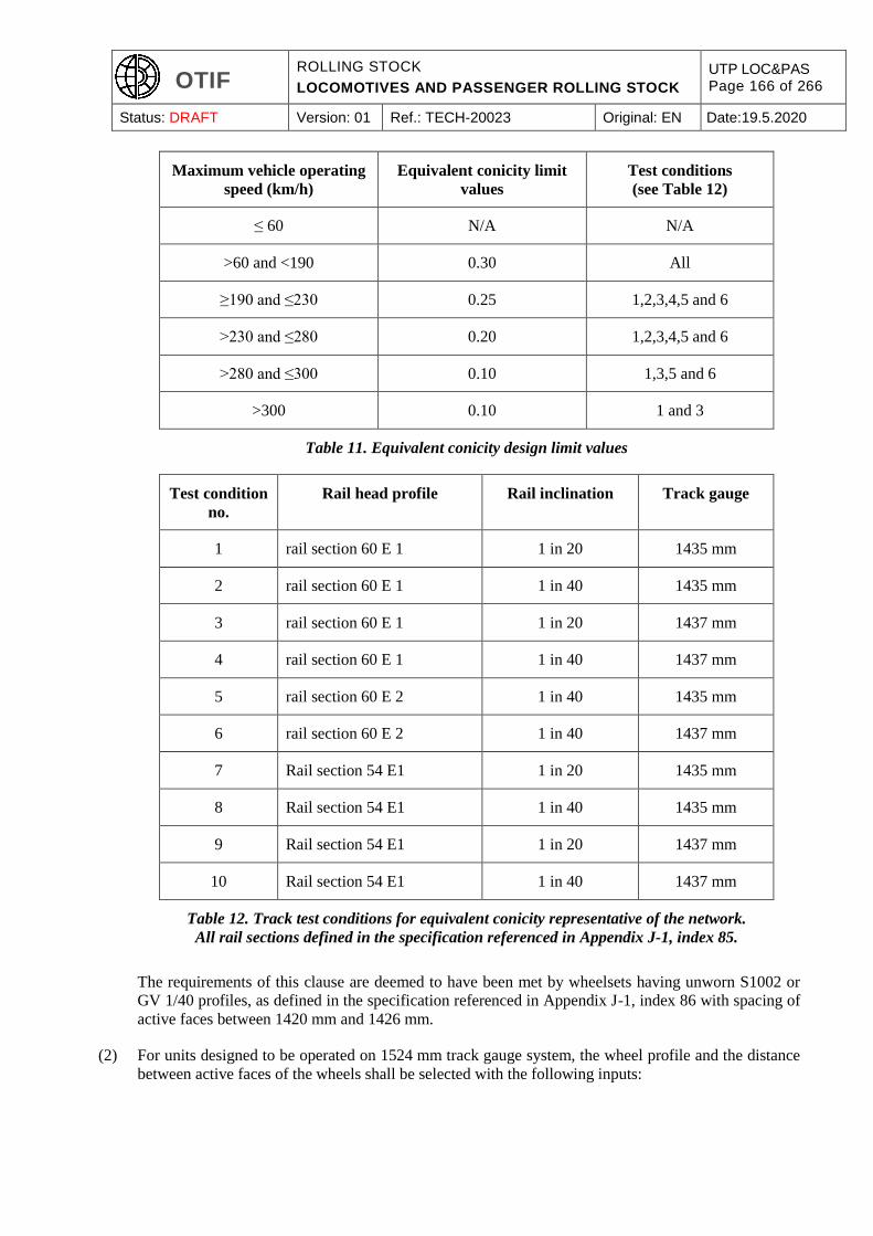
OTIF ROLLING STOCK
LOCOMOTIVES AND PASSENGER ROLLING STOCK
UTP LOC&PAS Page 166 of 266
Status: DRAFT Version: 01 Ref.: TECH-20023 Original: EN Date:19.5.2020
Maximum vehicle operating
speed (km/h)
Equivalent conicity limit
values
Test conditions
(see Table 12)
≤ 60 N/A N/A
>60 and <190 0.30 All
≥190 and ≤230 0.25 1,2,3,4,5 and 6
>230 and ≤280 0.20 1,2,3,4,5 and 6
>280 and ≤300 0.10 1,3,5 and 6
>300 0.10 1 and 3
Table 11. Equivalent conicity design limit values
Test condition
no.
Rail head profile Rail inclination Track gauge
1 rail section 60 E 1 1 in 20 1435 mm
2 rail section 60 E 1 1 in 40 1435 mm
3 rail section 60 E 1 1 in 20 1437 mm
4 rail section 60 E 1 1 in 40 1437 mm
5 rail section 60 E 2 1 in 40 1435 mm
6 rail section 60 E 2 1 in 40 1437 mm
7 Rail section 54 E1 1 in 20 1435 mm
8 Rail section 54 E1 1 in 40 1435 mm
9 Rail section 54 E1 1 in 20 1437 mm
10 Rail section 54 E1 1 in 40 1437 mm
Table 12. Track test conditions for equivalent conicity representative of the network.
All rail sections defined in the specification referenced in Appendix J-1, index 85.
The requirements of this clause are deemed to have been met by wheelsets having unworn S1002 or
GV 1/40 profiles, as defined in the specification referenced in Appendix J-1, index 86 with spacing of
active faces between 1420 mm and 1426 mm.
(2) For units designed to be operated on 1524 mm track gauge system, the wheel profile and the distance
between active faces of the wheels shall be selected with the following inputs:
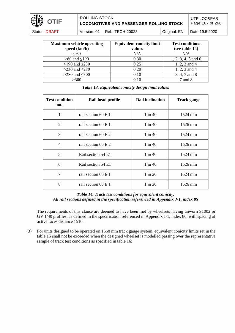
OTIF ROLLING STOCK
LOCOMOTIVES AND PASSENGER ROLLING STOCK
UTP LOC&PAS Page 167 of 266
Status: DRAFT Version: 01 Ref.: TECH-20023 Original: EN Date:19.5.2020
Maximum vehicle operating
speed (km/h)
Equivalent conicity limit
values
Test conditions
(see table 14)
≤ 60 N/A N/A
>60 and ≤190 0.30 1, 2, 3, 4, 5 and 6
>190 and ≤230 0.25 1, 2, 3 and 4
>230 and ≤280 0.20 1, 2, 3 and 4
>280 and ≤300 0.10 3, 4, 7 and 8
>300 0.10 7 and 8
Table 13. Equivalent conicity design limit values
Test condition
no.
Rail head profile Rail inclination Track gauge
1 rail section 60 E 1 1 in 40 1524 mm
2 rail section 60 E 1 1 in 40 1526 mm
3 rail section 60 E 2 1 in 40 1524 mm
4 rail section 60 E 2 1 in 40 1526 mm
5 Rail section 54 E1 1 in 40 1524 mm
6 Rail section 54 E1 1 in 40 1526 mm
7 rail section 60 E 1 1 in 20 1524 mm
8 rail section 60 E 1 1 in 20 1526 mm
Table 14. Track test conditions for equivalent conicity.
All rail sections defined in the specification referenced in Appendix J-1, index 85
The requirements of this clause are deemed to have been met by wheelsets having unworn S1002 or
GV 1/40 profiles, as defined in the specification referenced in Appendix J-1, index 86, with spacing of
active faces distance 1510.
(3) For units designed to be operated on 1668 mm track gauge system, equivalent conicity limits set in the
table 15 shall not be exceeded when the designed wheelset is modelled passing over the representative
sample of track test conditions as specified in table 16:

OTIF ROLLING STOCK
LOCOMOTIVES AND PASSENGER ROLLING STOCK
UTP LOC&PAS Page 168 of 266
Status: DRAFT Version: 01 Ref.: TECH-20023 Original: EN Date:19.5.2020
Maximum vehicle operating
speed (km/h)
Equivalent conicity limit
values
Test conditions
(see table 16)
≤ 60 N/A N/A
>60 and <190 0.30 All
≥190 and ≤ 230 0.25
1and 2
>230 and ≤280 0.20 1 and 2
>280 and ≤300 0.10 1and 2
>300 0.10 1 and 2
Table 15. Equivalent conicity design limit values
Test condition
No.
Rail head profile Rail inclination Track gauge
1 Rail section 60 E 1 1 in 20 1668 mm
2 Rail section 60 E 1 1 in 20 1670 mm
3 Rail section 54 E1 1 in 20 1668 mm
4 Rail section 54 E1 1 in 20 1670 mm
Table 16. Track test conditions for equivalent conicity.
All rail sections defined in the specification referenced in Appendix J-1, index 85.
The requirements of this clause are deemed to have been met by wheelsets having unworn S1002 or
GV 1/40 profiles, as defined in the specification referenced in Appendix J-1, index 86 with spacing of
active faces between 1653 mm and 1659 mm.
6.2.3.7. Mechanical and geometric characteristics of wheelsets (clause 4.2.3.5.2.1)
Wheelset:
(1) The demonstration of compliance for the assembly shall be based on the specification referenced in
Appendix J-1, index 87, which defines limit values for the axial force, and the associated verification
tests.
Axles:
(2) The demonstration of compliance for mechanical resistance and fatigue characteristics of the axle shall
be in accordance with the specification referenced in Appendix J-1, index 88, clauses 4, 5 and 6 for
non-powered axles, or the specification referenced in Appendix J-1, index 89, clauses 4, 5 and 6 for
powered axles.
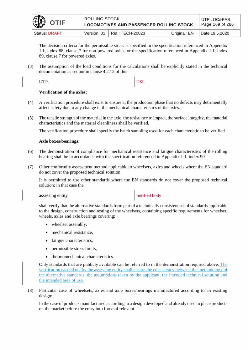
OTIF ROLLING STOCK
LOCOMOTIVES AND PASSENGER ROLLING STOCK
UTP LOC&PAS Page 169 of 266
Status: DRAFT Version: 01 Ref.: TECH-20023 Original: EN Date:19.5.2020
The decision criteria for the permissible stress is specified in the specification referenced in Appendix
J-1, index 88, clause 7 for non-powered axles, or the specification referenced in Appendix J-1, index
89, clause 7 for powered axles.
(3) The assumption of the load conditions for the calculations shall be explicitly stated in the technical
documentation as set out in clause 4.2.12 of this
UTP. TSI.
Verification of the axles:
(4) A verification procedure shall exist to ensure at the production phase that no defects may detrimentally
affect safety due to any change in the mechanical characteristics of the axles.
(5) The tensile strength of the material in the axle, the resistance to impact, the surface integrity, the material
characteristics and the material cleanliness shall be verified.
The verification procedure shall specify the batch sampling used for each characteristic to be verified.
Axle boxes/bearings:
(6) The demonstration of compliance for mechanical resistance and fatigue characteristics of the rolling
bearing shall be in accordance with the specification referenced in Appendix J-1, index 90.
(7) Other conformity assessment method applicable to wheelsets, axles and wheels where the EN standard
do not cover the proposed technical solution:
It is permitted to use other standards where the EN standards do not cover the proposed technical
solution; in that case the
assessing entity notified body
shall verify that the alternative standards form part of a technically consistent set of standards applicable
to the design, construction and testing of the wheelsets, containing specific requirements for wheelset,
wheels, axles and axle bearings covering:
wheelset assembly,
mechanical resistance,
fatigue characteristics,
permissible stress limits,
thermomechanical characteristics.
Only standards that are publicly available can be referred to in the demonstration required above. The
verification carried out by the assessing entity shall ensure the consistency between the methodology of
the alternative standards, the assumptions taken by the applicant, the intended technical solution and
the intended area of use.
(8) Particular case of wheelsets, axles and axle boxes/bearings manufactured according to an existing
design:
In the case of products manufactured according to a design developed and already used to place products
on the market before the entry into force of relevant
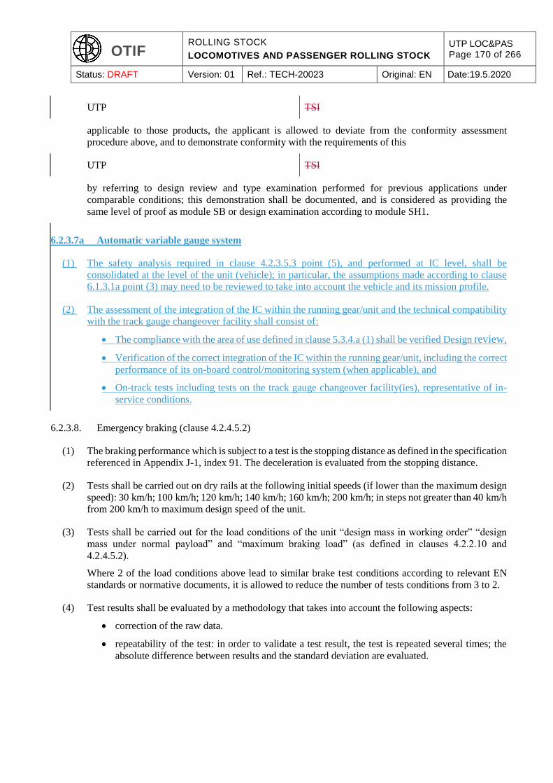
OTIF ROLLING STOCK
LOCOMOTIVES AND PASSENGER ROLLING STOCK
UTP LOC&PAS Page 170 of 266
Status: DRAFT Version: 01 Ref.: TECH-20023 Original: EN Date:19.5.2020
UTP TSI
applicable to those products, the applicant is allowed to deviate from the conformity assessment
procedure above, and to demonstrate conformity with the requirements of this
UTP TSI
by referring to design review and type examination performed for previous applications under
comparable conditions; this demonstration shall be documented, and is considered as providing the
same level of proof as module SB or design examination according to module SH1.
6.2.3.7a Automatic variable gauge system
(1) The safety analysis required in clause 4.2.3.5.3 point (5), and performed at IC level, shall be
consolidated at the level of the unit (vehicle); in particular, the assumptions made according to clause
6.1.3.1a point (3) may need to be reviewed to take into account the vehicle and its mission profile.
(2) The assessment of the integration of the IC within the running gear/unit and the technical compatibility
with the track gauge changeover facility shall consist of:
The compliance with the area of use defined in clause 5.3.4.a (1) shall be verified Design review,
Verification of the correct integration of the IC within the running gear/unit, including the correct
performance of its on-board control/monitoring system (when applicable), and
On-track tests including tests on the track gauge changeover facility(ies), representative of in-
service conditions.
6.2.3.8. Emergency braking (clause 4.2.4.5.2)
(1) The braking performance which is subject to a test is the stopping distance as defined in the specification
referenced in Appendix J-1, index 91. The deceleration is evaluated from the stopping distance.
(2) Tests shall be carried out on dry rails at the following initial speeds (if lower than the maximum design
speed): 30 km/h; 100 km/h; 120 km/h; 140 km/h; 160 km/h; 200 km/h; in steps not greater than 40 km/h
from 200 km/h to maximum design speed of the unit.
(3) Tests shall be carried out for the load conditions of the unit “design mass in working order” “design
mass under normal payload” and “maximum braking load” (as defined in clauses 4.2.2.10 and
4.2.4.5.2).
Where 2 of the load conditions above lead to similar brake test conditions according to relevant EN
standards or normative documents, it is allowed to reduce the number of tests conditions from 3 to 2.
(4) Test results shall be evaluated by a methodology that takes into account the following aspects:
correction of the raw data.
repeatability of the test: in order to validate a test result, the test is repeated several times; the
absolute difference between results and the standard deviation are evaluated.

OTIF ROLLING STOCK
LOCOMOTIVES AND PASSENGER ROLLING STOCK
UTP LOC&PAS Page 171 of 266
Status: DRAFT Version: 01 Ref.: TECH-20023 Original: EN Date:19.5.2020
6.2.3.9. Service braking (clause 4.2.4.5.3)
(1) The maximum service braking performance which is subject to a test is the stopping distance as defined
in the specification referenced in Appendix J-1, index 92. The deceleration is evaluated from the
stopping distance.
(2) Tests shall be carried out on dry rail at the initial speed equal to the maximum design speed of the unit,
the load condition of the unit being one of those defined in the clause 4.2.4.5.2.
(3) Test results shall be evaluated by a methodology that takes into account the following aspects:
correction of the raw data.
repeatability of the test: in order to validate a test result, the test is repeated several times; the
absolute difference between results and the standard deviation are evaluated.
6.2.3.10. Wheel slide protection system (clause 4.2.4.6.2)
(1) If a unit is equipped with a WSP, a test of the unit in low adhesion conditions shall be carried out
according to the specification referenced in Appendix J-1, index 93, in order to validate the performance
of the WSP system (maximum extension of the stopping distance compared to stopping distance on dry
rail) when integrated in the unit.
6.2.3.11. Sanitary systems (clause 4.2.5.1)
(1) In case the sanitary system allows the release of fluids to the environment (e.g. on the tracks), the
assessment of conformity may be based on previous in-service testing when the following conditions
are met:
The results of the in service tests were obtained on types of equipment which have an identical
treatment method.
The conditions of test are similar as the ones that may be assumed for the unit under assessment,
with regard to loading volumes, environmental conditions, and all other parameters which will
influence the efficiency and effectiveness of the treatment process.
If suitable in-service testing results are lacking, type tests shall be performed.
6.2.3.12. Internal air quality (clause 4.2.5.8 and clause 4.2.9.1.7)
(1) Conformity assessment of the CO2-levels is permitted to be established by calculation of fresh air
ventilation volumes assuming an outside air quality containing 400 ppm CO2 and an emission of 32
grams of CO2 per passenger per hour. The number of passengers to be taken into account shall be
derived from the occupation under the load condition ‘design mass under normal payload’, as stipulated
in clause 4.2.2.10 of this
UTP. TSI.
6.2.3.13. Slipstream effects on passengers on platform and on workers trackside (clause 4.2.6.2.1)
(1) Demonstration of conformity with the limit value of trackside maximum permissible air speed set out
in clause 4.2.6.2.1 of this UTP shall be demonstrated on the basis of full-scale tests on straight track
performed in accordance with clause 6.2.2.1 of specification referenced in Appendix J-1, index 94.
OTIF ROLLING STOCK
LOCOMOTIVES AND PASSENGER ROLLING STOCK
UTP LOC&PAS Page 172 of 266
Status: DRAFT Version: 01 Ref.: TECH-20023 Original: EN Date:19.5.2020
(2) Instead of the full assessment described above, it is permitted to carry out a simplified assessment for
rolling stock of a similar design to rolling stock for which the full assessment defined in this UTP has
been carried out. In such cases, the simplified conformity assessment defined in clause 4.2.4 of the
specification referenced in Appendix J-1, index 94, can be applied as long as the differences in the
design remain within the limits of table 7 of the specification referenced in Appendix J-1, index 94.
(1) Conformity shall be assessed on the basis of full-scale tests on straight track. The vertical
distance between the top of the rail and the surrounding ground level up to 3 m from the track
centre shall be within the range of 0,50 m and 1,50 m below the top of the rail. The values of
u2σ are the upper bound of the 2σ confidence interval of the maximum resultant induced air
speeds in the horizontal plane at the above measurements positions. These shall be obtained
from at least 20 independent and comparable test samples with ambient wind speeds less than
or equal to 2 m/s.
U2σ is given by:
U2σ = Ū + 2σ
with
Ū mean value of all air speed measurements U i,, for i train passages, where i≥20
σ standard deviation of all air speed measurements U i,, for i train passages, where i≥20
(2) The measurements shall consist of the time period starting 4 s second before the passing of
the first axle and continue until 10 s after the last axle has passed.
The tested train speed vtr,test.
Vtr,test = vtr,ref, or
vtr,test = 250 km/h or vtr,max whichever is lower.
At least 50 % of the train passages shall be within ± 5 % of the vtr,test and all train passages
shall be within ± 10 % of the vtr,test
(3) All valid measurements shall be used in the post processing of the data.
Each measurement U m,i shall be corrected:
Ui = Um,i * vtr,ref/vtr,i
where vtr,i is the train speed for test run i and vtr,ref is the reference train speed.
(4) The test site shall be free from any objects providing from sheltering against the train-induced
air flow.
(5) Meteorological conditions during tests shall be observed as per the specification referenced in
Appendix J-1, index 94.
(6) Sensors, accuracy, selection of valid data and processing of the data shall be in accordance
with the specification referenced in Appendix J-1, index 94.
6.2.3.14. Head pressure pulse (clause 4.2.6.2.2)
(1) Conformity shall be assessed on the basis of full-scale tests under conditions specified in the
specification referenced in Appendix J-1, index 95, clause 6.1.2.15.5.2. Alternatively conformity may
be assessed by means of either validated Computational Fluid Dynamics (CFD) simulations as
described in the specification referenced in Appendix J-1, index 95, clause 5.36.1.2.4 or as an additional

OTIF ROLLING STOCK
LOCOMOTIVES AND PASSENGER ROLLING STOCK
UTP LOC&PAS Page 173 of 266
Status: DRAFT Version: 01 Ref.: TECH-20023 Original: EN Date:19.5.2020
alternative conformity is permitted to be assessed by moving model tests as specified in the specification
referenced in Appendix J-1, index 95, clause 5.4.36.1.2.2.
(2) Instead of the full assessment described above, it is permitted to carry out a simplified assessment for
rolling stock of a similar design to rolling stock for which the full assessment defined in this UTP has
been carried out. In such cases, the simplified conformity assessment defined in clause 4.1.4 of the
specification referenced in Appendix J-1, index 95, can be applied as long as the differences in the
design remain within the limits of table 4 of the specification referenced in Appendix J-1, index 95.
6.2.3.15. Maximum pressure variations in tunnels (clause 4.2.6.2.3)
(1) Conformity shall be proven on the basis of full-scale tests, carried out at reference speed or at a higher
speed in a tunnel with a cross-sectional area as close to the reference case as possible. Transfer to the
reference condition shall be done with validated simulation software.
(2) When assessing conformity of whole trains or trainsets, assessment shall be made with the maximum
length of the train or coupled trainsets up to 400 m.
(3) When assessing conformity of locomotives or driving coaches, assessment shall be done on a basis of
two arbitrary train compositions of minimum length 150 m, one with a leading locomotive or driving
coach (to check the ΔpN) and one with a locomotive or a driving coach at the end (to check ΔpT). ΔpFr
is set to 1250 Pa (for trains with vtr,max < 250 km/h) or to 1400 Pa (for trains with vtr,max ≥ 250 km/h).
(4) When assessing conformity of coaches only, assessment shall be done on the basis of one 400 m long
train.
(5) ΔpN is set to 1750 Pa and ΔpT to 700 Pa (for trains with vtr,max < 250 km/h) or to 1600 Pa and 1100 Pa
(for trains with vtr,max ≥ 250 km/h).
(6) For the distance xp between the entrance portal and the measuring position, the definitions of ΔpFr,
ΔpN, ΔpT, the minimum tunnel length and further information about the derivation of the characteristic
pressure variation, see the specification referenced in Appendix J-1, index 96.
(7) The pressure change due to altitude changes between the entry and the exit point in the tunnel shall not
be taken into account in the assessment.
6.2.3.16. Cross wind (clause 4.2.6.2.4)
(1) Conformity assessment is fully specified in clause 4.2.6.2.4
6.2.3.17. Warning Horn sound pressure levels (clause 4.2.7.2.2)
(1) Sound pressure levels of the warning horn shall be measured and verified in accordance with the
specification referenced in Appendix J-1, index 97.
6.2.3.18. Maximum power and current from the overhead contact line (clause 4.2.8.2.4)
(1) Conformity assessment shall be carried out in accordance with the specification referenced in Appendix
J-1, index 98.
OTIF ROLLING STOCK
LOCOMOTIVES AND PASSENGER ROLLING STOCK
UTP LOC&PAS Page 174 of 266
Status: DRAFT Version: 01 Ref.: TECH-20023 Original: EN Date:19.5.2020
6.2.3.19. Power factor (clause 4.2.8.2.6)
(1) Conformity assessment shall be carried out according to the specification referenced in Appendix J-1,
index 99.
6.2.3.19a On-board energy measurement system (clause 4.2.8.2.8)
(1) Energy measurement function (EMF)
The accuracy of each device containing one or more functions of EMF shall be assessed by testing each
function, under reference conditions, using the relevant method as described in clauses 5.4.3.4.1,
5.4.3.4.2 and 5.4.4.3.1 of the specification referenced in Appendix J-1, index 117. The input quantity
and power factor range when testing shall correspond to the values set out in Table 3 of the specification
referenced in Appendix J-1, index 117.
The effects of temperature on accuracy of each device containing one or more functions of EMF shall
be assessed by testing each function, under reference conditions (except for temperature), using the
relevant method as described in clauses 5.4.3.4.3.1, and 5.4.4.3.2.1 of the specification referenced in
Appendix J-1, index 117.
The mean temperature coefficient of each device containing one or more functions of EMF shall be
assessed by testing each function, under reference conditions (except for temperature), using the
relevant method as described in clauses 5.4.3.4.3.2 and 5.4.4.3.2.2 of the specification referenced in
Appendix J-1, index 120.
(2) Data handling system (DHS)
The compiling and handling of data within the DHS shall be assessed by testing using the method as
described in the specification referenced in Appendix J-1, index 121.
(3) On-board energy measurement system (EMS)
The EMS shall be assessed by testing as described in the specification referenced in the specification
referenced in Appendix J-1, index 122.
6.2.3.20. Current collection dynamic behaviour (clause 4.2.8.2.9.6)
(1) When a pantograph,
already assessed separately holding an EC declaration of conformity or
suitability for use as IC,
is integrated in a rolling stock unit which is assessed according to the
UTP LOC&PAS, LOC&PAS TSI,
dynamic tests shall be carried out in order to measure the mean contact force and standard deviation or
the percentage of arcing, in accordance with the specification referenced in Appendix J-1, index 100 up
to the design speed for the unit.
(2) For a unit designed to be operated on the 1435 mm and 1668 mm track gauge systems, the tests, for
each installed pantograph, shall be conducted in both directions of travel and shall include track sections
with low contact wire height (defined as between 5.0 to 5.3 m) and track sections with high contact wire
height (defined as between 5.5 to 5.75 m).

OTIF ROLLING STOCK
LOCOMOTIVES AND PASSENGER ROLLING STOCK
UTP LOC&PAS Page 175 of 266
Status: DRAFT Version: 01 Ref.: TECH-20023 Original: EN Date:19.5.2020
For units designed to be operated on the 1520 mm and 1524 mm track gauge systems, the tests shall
include track sections with contact wire height between 6.0 to 6.3 m.
(3) The tests shall be performed for a minimum of 3 speed increments up to and including the design speed
of the unit. The interval between successive tests shall be no greater than 50 km/h.
(4) During the test, the static contact force shall be adjusted for each particular power supply system within
the range, as specified in clause 4.2.8.2.9.5).
(5) The measured results shall be in accordance with the clause 4.2.8.2.9.6 for either mean contact force
and standard deviation or percentage of arcing.
6.2.3.21. Arrangement of pantographs (clause 4.2.8.2.9.7)
(1) The characteristics related to the dynamic behaviour of the current collection shall be verified as
specified in clause 6.2.3.20 above.
6.2.3.22. Windscreen (clause 4.2.9.2)
(1) The characteristics of the windscreen shall be verified as specified in the specification referenced in
Appendix J-1, index 101.
6.2.3.23. Fire detection systems (clause 4.2.10.3.2)
(1) The requirement 4.2.10.3.2 (1) shall be deemed to be satisfied by the verification that the rolling stock
is equipped with a fire detection system in the following areas:
technical compartment or cabinet, sealed or not sealed, containing electrical supply line and/or
traction circuit equipment,
technical area with a combustion engine,
in sleeping cars and sleeping compartments, including their staff compartments and their
adjacent gangways and their adjacent combustion heating equipment.
6.2.4. Project phases where assessment is required
(1) It is detailed in Appendix H of this
UTP TSI
in which phase of the project an assessment shall be done:
Design and development phase:
Design review and/or design examination
Type test: test to verify the design, if and as defined in the section 4.2.
Production phase: routine test to verify the conformity of production.
The entity in charge of the assessment of the routine tests is determined according to the
assessment module chosen.
OTIF ROLLING STOCK
LOCOMOTIVES AND PASSENGER ROLLING STOCK
UTP LOC&PAS Page 176 of 266
Status: DRAFT Version: 01 Ref.: TECH-20023 Original: EN Date:19.5.2020
(2) The Appendix H is structured according to the section 4.2, which defines the requirements and their
assessment applicable to the rolling stock sub-system; where relevant, a reference to a sub-clause of the
clause 6.2.2.2 above is also given.
In particular, where a type test is identified in the Appendix H, the section 4.2 shall be considered for
the conditions and requirements related to this test.
(3) Where several
verifications EC verifications
(e.g. against several
UTPs TSIs
addressing the same sub-system) require verification based on the same production assessment (module
SD or SF), it is allowed to combine several SB module assessments with one production module
assessment (SD or SF). In this case, ISVs shall be issued for the design and development phases
according to module SB.
(4) If module SB is used, the validity of the declaration of intermediate subsystem conformity shall be
indicated in accordance with the provisions for phase B of clause 7.1.3
of this UTP. ‘Rules related to the EC verification’, of this TSI.
6.2.5. Innovative solutions
(1) If an innovative solution
(as defined in Article 3a of ATMF), (as defined in Article 10),
is proposed for the rolling stock subsystem, the applicant shall apply the procedure described
below:
In order to keep pace with technological progress,
innovative solutions may be required, which do
not comply with the specifications set out in this
UTP and/or to which the assessment methods set
out in this UTP cannot be applied. In that case,
new specifications and/or new assessment
methods associated with those innovative
solutions shall be developed.
Innovative solutions may be related to the rolling
stock subsystem, its parts and its ICs.
If an innovative solution is proposed, the
manufacturer or his authorised representative shall
declare how it intends to deviates from or
complements the relevant provisions of this UTP.
On the basis of this declaration, one of the entities
listed in Article 6 § 2 of APTU, or the Secretary
General may and submit the new specifications
in article 10.
OTIF ROLLING STOCK
LOCOMOTIVES AND PASSENGER ROLLING STOCK
UTP LOC&PAS Page 177 of 266
Status: DRAFT Version: 01 Ref.: TECH-20023 Original: EN Date:19.5.2020
and/or new assessment methods to the deviations
to the Secretary GeneralCommittee of Technical
Experts (CTE) for analysis and approval. The
Secretary General will coordinate its opinion with
the EU and the European Railway Agency (the
Agency) on the proposed innovative solution and
submit its opinion to the CTE.
If the CTE supports the new specifications and/or
new assessment methods opinion, the appropriate
functional and interface specifications and the
assessment method, which need must to be
included in the UTP in order to allow the use of
this innovative solution, shall be developed in
coordination with the EU and subsequently
integrated in the UTP during their respectiveits
revision processes.
Pending the revision of the UTP, the positive
Committee of Technical Experts CTE may already
opinion shall be consider edthe new specifications
and/or new assessment methods as an acceptable
means of compliance with the essential
requirements of UTP GEN-A. and may therefore
be used for the assessment of the subsystemIn such
case the Committee of Technical Experts CTE
should instruct the Secretary General as to how the
new specifications and/or new assessment methods
are to be communicated to the Contracting States
and made public.
6.2.6. Assessment of documentation requested for operation and maintenance
(1) The assessing entity According to Article 185 (34) of Directive
(EU)2016/7972008/57/EC, a Notified Body
shall be responsible for compiling the technical file, containing the documentation requested for
operation and maintenance.
(2) The assessing entity The notified body
shall verify only that the documentation requested for operation and maintenance, as defined in clause
4.2.12 of this
UTP, TSI,
is provided.
The assessing entity The notified body
is not required to verify the information contained in the documentation provided.

OTIF ROLLING STOCK
LOCOMOTIVES AND PASSENGER ROLLING STOCK
UTP LOC&PAS Page 178 of 266
Status: DRAFT Version: 01 Ref.: TECH-20023 Original: EN Date:19.5.2020
6.2.7. Assessment of units intended to be used in general operation
(1) Where a new, upgraded or renewed unit to be used in general operation is subject to assessment against
this
UTP TSI
(in accordance with clause 4.1.2), some of the
UTP TSI
requirements require a reference train for their assessment. This is mentioned in the relevant provisions
of section 4.2. Similarly, some of the
UTP TSI
requirements at train level cannot be assessed at unit level; such cases are described for the relevant
requirements in section 4.2 of this
UTP. TSI.
(2) The area of use in terms of type of RST which, coupled with the unit to be assessed, ensures that the
train is compliant with the
UTP TSI
is not verified by the
assessing entity. notified body.
(3) After such a unit has received the authorisation to be placed in service, its use in a train formation
(whether
UTP TSI
compliant or not) shall be dealt with under the responsibility of the railway undertaking, according to
the rules defined in
Appendix KUTP TCRC clause 4.2.2.5 of the OPE TSI
(train composition).
6.2.7a Additional optional requirements for units intended to be used in general operation
(1) The compliance with the following set of conditions (2) to (9) is optional and only aims to facilitate
exchange of units intended for general operations. Compliance with these provisions does not assure
full interchangeability of units and does not exempt the railway undertaking of its responsibilities
regarding the use of these units in a train formation as defined in clause 6.2.7. If the applicant selects
this option, a assessing entity has to assess the compliance within the UTP verification procedure. This
shall be reported in the certificate and in the technical documentation.
(2) The unit shall be fitted with a manual coupling system as defined in clauses 4.2.2.2.3 b) and 5.3.2.
OTIF ROLLING STOCK
LOCOMOTIVES AND PASSENGER ROLLING STOCK
UTP LOC&PAS Page 179 of 266
Status: DRAFT Version: 01 Ref.: TECH-20023 Original: EN Date:19.5.2020
(3) The unit shall be fitted with an EN-UIC braking system as defined in the specification referenced in
Appendix J-1, index 22.
(4) The unit shall meet the requirements of this UTP at least within the temperature range T1 (– 25 °C to +
40 °C; nominal) as defined in clause 4.2.6.1 of this UTP and in the specification referenced in Appendix
J-1, index 34.
(5) The tail lights requested in clause 4.2.7.1 shall be provided by fixed tail lamps.
(6) If the unit is fitted with a gangway, the gangway shall fulfil the specification referenced in Appendix J-
1, index 113.
(7) Power supply shall be compliant to point 4 of clause 4.2.11.6.
(8) The physical interface between units for the signal transmission shall ensure that the cable and plug of
at least one line is compatible with the 18-conductor cable defined in the plate 2 of the specification
referenced in Appendix J-1, index 114.
(9) The unit shall be marked at least with the following markings in accordance with the specification
referenced in Appendix J-1, index 115:
Length over buffers.
Electric power supply.
6.2.8. Assessment of units intended to be used in pre-defined formation(s)
(1) Where a new, upgraded or renewed unit to be included in pre-defined formation(s) is subject to
assessment (in accordance with chapter 4.1.2), the
UTP certificate of verification EC certificate of verification
shall identify the formation(s) for which the assessment is valid: the type of RST coupled with the unit
to be assessed, number of vehicles in the formation(s), arrangement of the vehicles in the formation(s)
that will ensure that the train formation will be compliant with this
UTP. TSI.
(2) UTP TSI
requirements at train level shall be assessed with use of a reference train formation when and as
specified in this
UTP. TSI.
(3) After such a unit has received the authorisation to be placed in service, it may be coupled with other
units to constitute the formations mentioned in the
UTP certificate of verification. EC certificate of verification.
OTIF ROLLING STOCK
LOCOMOTIVES AND PASSENGER ROLLING STOCK
UTP LOC&PAS Page 180 of 266
Status: DRAFT Version: 01 Ref.: TECH-20023 Original: EN Date:19.5.2020
6.2.9. Particular case: Assessment of units intended to be included in an existing fixed formation
6.2.9.1. Context
(1) This particular case of assessment applies in case of replacement of a part of a fixed formation, which
has already been placed in service.
Two cases are described below, depending on the
UTP TSI
status of the fixed formation.
The part of the fixed formation subject to the assessment is called “unit” in the text below.
6.2.9.2. Case of a UTP compliant fixed formation Case of a TSI compliant fixed formation
(1) Where a new, upgraded or renewed unit to be included in an existing fixed formation is subject to
assessment against this
UTP TSI
and a valid
UTP certificate of verification EC certificate of verification
for the existing fixed formation is available, a
UTP TSI
assessment only for the new part of the fixed formation is required in order to update the certificate of
the existing fixed formation, which is considered as renewed (see also clause 7.1.2.2).
6.2.9.3. Case of a non-UTP compliant fixed formation Case of a non-TSI compliant fixed formation
(1) Where a new, upgraded or renewed unit to be included in an existing fixed formation is subject to
assessment against this
UTP, TSI,
and a valid
UTP certificate of verification EC certificate of verification
for the existing fixed formation is not available, the
UTP certificate of verification EC certificate of verification
OTIF ROLLING STOCK
LOCOMOTIVES AND PASSENGER ROLLING STOCK
UTP LOC&PAS Page 181 of 266
Status: DRAFT Version: 01 Ref.: TECH-20023 Original: EN Date:19.5.2020
shall state that the assessment does not cover the
UTP TSI
requirements applicable to the fixed formation, but only the assessed unit.
6.3. Subsystem containing interoperability constituents
which have not been certified according to
the UTP
not holding an EC declaration
This Section is without prejudice to Section 6.1 of
this UTP29.
6.3.1. Conditions
(1) During the transitional period ending on 31 May 2017, a/an
assessing entity notified body
is permitted to issue an/a
UTP certificate of verification EC certificate of verification
for a subsystem, even if some of the interoperability constituents incorporated within the subsystem are
not covered by the relevant
UTP certificatedeclaration EC declarations
of conformity or suitability for use according to this
UTP TSI
(non-certified ICs), if the following criteria are complied with:
a) The conformity of the subsystem has been checked against the requirements of section 4 and in
relation to sections 6.2 to 7 (except ‘Specific cases’) of this
UTP TSI
by the
Assessing Entity. Notified Body.
Furthermore the conformity of the IC to sections 5 and 6.1 does not apply, and
b) The interoperability constituents, which are not covered by the relevant
29 Which means that the separate assessment of ICs is not mandatory by default, and the provisions in this section are only applicable if an IC is assessed separately.
OTIF ROLLING STOCK
LOCOMOTIVES AND PASSENGER ROLLING STOCK
UTP LOC&PAS Page 182 of 266
Status: DRAFT Version: 01 Ref.: TECH-20023 Original: EN Date:19.5.2020
UTP certificatedeclaration EC declaration
of conformity or suitability for use, have been used in a subsystem already approved and put in
service in at least one of the
Contracting States Member States
before the date of application of this
UTP. TSI.
(2) UTP EC
declarations of conformity or suitability for use shall not be drawn up for the interoperability
constituents assessed in this manner.
6.3.2. Documentation
(1) The UTP certificate of verification The EC certificate of verification
of the subsystem shall indicate clearly which interoperability constituents have been assessed by the
assessing entity notified body
as part of the subsystem verification.
(2) The UTP The EC
declaration of verification of the subsystem shall indicate clearly:
a) Which interoperability constituents have been assessed as part of the subsystem;
b) Confirmation that the subsystem contains the interoperability constituents identical to those
verified as part of the subsystem;
c) For those interoperability constituents, the reason(s) why the manufacturer did not provide an
UTP EC
declaration of conformity or suitability for use before its incorporation into the subsystem,
including the application of national rules
notified under Article 12 of APTU. notified under Article 147 of Directive (EU)
2016/7972008/57/EC.
6.3.3. Maintenance of the subsystems certified according to clause 6.3.1
(1) During the transition period as well as after the transition period has ended, until the subsystem is
upgraded, renewed (taking into account the
CS MS
OTIF ROLLING STOCK
LOCOMOTIVES AND PASSENGER ROLLING STOCK
UTP LOC&PAS Page 183 of 266
Status: DRAFT Version: 01 Ref.: TECH-20023 Original: EN Date:19.5.2020
decision on application of
UTP), TSI),
the interoperability constituents which do not hold
a UTP certificatedeclaration an EC declaration
of conformity or suitability for use and of the same type are permitted to be used as maintenance related
replacements (spare parts) for the subsystem, under the responsibility of the ECM.
(2) In any case the ECM must ensure that the components for maintenance related replacements are suitable
for their applications, are used within their area of use, and enable interoperability to be achieved within
the rail system while at the same time meeting the essential requirements. Such components must be
traceable and certified in accordance with any national or international rule, or any code of practice
widely acknowledged in the railway domain.
7. IMPLEMENTATION
7.1. General rules for implementation
7.1.1. Application to newly built rolling stock
7.1.1.1. General
(1) This
UTP TSI
is applicable to all units of rolling stock in its scope which
are subject to an admission to operation in
international traffic
are placed in service
after the date of
entry into force of this UTP1 January 2015,. the date of application set out in Article 12,
except where clause 7.1.1.2 “Transition phase” or clause 7.1.1.3 “Application to special vehicles, such
as on-track machinesOTMs” or clause 7.1.1.4 “Application to vehicle designed to be operated solely
on 1520 mm system” below apply.
(2) This
UTP TSI
does not apply to units of existing rolling stock which are already
admitted to international operation placed in service on the network (or part of the
network) of one Member State

OTIF ROLLING STOCK
LOCOMOTIVES AND PASSENGER ROLLING STOCK
UTP LOC&PAS Page 184 of 266
Status: DRAFT Version: 01 Ref.: TECH-20023 Original: EN Date:19.5.2020
at the time when the
by 1 January 2015UTP at the time when the TSI becomes applicable,
becomes applicable, as long as they are not upgraded or renewed (see clause 7.1.2).
(3) Any rolling stock which is produced according to a design developed after the date of application of
this
UTP1 January 2015 the date of application of this TSI
shall be compliant with this
UTP if it is to be admitted to international traffic in
accordance with ATMF.
TSI.
7.1.1.2. Transition phase
7.1.1.2.1 Application of the
UTP TSI
during transition phase
(1) A significant number of projects or contracts, which started before the date of application of this
UTP, TSI,
may lead to the production of rolling stock which does not fully comply with this
UTP. TSI.
For rolling stock concerned by those projects or contracts, and in accordance with
point (f) of Article 8§4 of APTU, point (f) of Article 54(3) of Directive (EU)
2016/7972008/57/EC,
a transition phase is defined, during which the application of this
during which this UTP may be partially applied. during which the application of this TSI is not
mandatory
is not mandatory.
(2) This transition phase applies to:
Projects at advanced stage of development, as defined in the clause 7.1.1.2.2
Contracts in course of performance, as defined in the clause 7.1.1.2.3
Rolling stock of an existing design, as defined in clause 7.1.1.2.4.
(3) For rolling stock which falls under one of the three
cases above, the application of this UTP is not
The application of this TSI to rolling stock which
falls under one of the three cases above is not
OTIF ROLLING STOCK
LOCOMOTIVES AND PASSENGER ROLLING STOCK
UTP LOC&PAS Page 185 of 266
Status: DRAFT Version: 01 Ref.: TECH-20023 Original: EN Date:19.5.2020
mandatory during a transitional period ending on
31.12.2020.
During the transitional period, the applicant may
choose to apply, or partly apply, the UTP on a
voluntary basis. In such a case, application of the
UTP takes precedence over the application of
national technical requirements
If this UTP is applied, Contracting States shall
mutually recognise UTP compliance or partial
UTP compliance when admitting vehicles to
international traffic on their territory under the
provisions of Article 6 § 4 of ATMF.
.
mandatory if one of the following conditions is
met:
In case the rolling stock is in the scope of the
TSI HS RST TSI 2008 or of the TSI CR
LOC&PAS TSI 2011, the relevant TSI(s),
including implementation rules and period of
validity of the “type or design examination
certificate” (7 years) are applied. This
provision shall not apply to vehicles that are
not conform to the HS RST TSI 2008 or to
the CR LOC&PAS TSI 2011 and that are
placed on the market after 31 May 2017.
In case the rolling stock is in the scope of
neither the HS RST TSI 2008 nor the CR
LOC&PAS TSI 2011: the authorisation for
placing on the marketin service is delivered
during a transition period ending on 31
December 2020.6 years after the date of
application of this TSI.
(4) During the transition phase, if the applicant chooses not to apply this
UTP, the rolling stock shall be subject to
requirements applicable in the Contracting States
in which the rolling stock is admitted to operation
in accordance with Article 6 § 4 of ATMF.
TSI, it is reminded that the other TSIs (see section
2.1) and/or notified national rules apply according
to their respective scopes and implementation
rules for the authorisation to place on the market
in accordance with Article 21 of Directive (EU)
2016/797in service in accordance with Articles 22
to 25 of Directive 2008/57/EC.
In particular, TSIs to be repealed by this TSI
continue to apply, under the conditions stated in
Article 11.
7.1.1.2.2 Definition of Projects at advanced stage of development
(1) Rolling stock is developed and produced under a project at an advanced stage of development in
accordance with the definition in Article 2 of the
Article 2 of the APTU. point (23) of Article 2 of Directive (EU)
2016/797Directive
(2) The project shall be at an advanced stage of development at the date of application of this
UTP. at the date of application of this TSI.
7.1.1.2.3 Definition of Contracts in course of performance
(1) Rolling stock is developed and produced under a contract which is signed before the date of application
of this
OTIF ROLLING STOCK
LOCOMOTIVES AND PASSENGER ROLLING STOCK
UTP LOC&PAS Page 186 of 266
Status: DRAFT Version: 01 Ref.: TECH-20023 Original: EN Date:19.5.2020
UTP. TSI.
(2) The applicant has to bring evidence of the date of signature of the original contract applicable. The date
of any addenda in the form of changes to an original contract shall not be taken into account when
defining the date of signature of the contract in question.
7.1.1.2.4 Definition of Rolling Stock of an existing design
(1) (reserved) Rolling stock is produced according to a design
developed before the date of application of this
TSI, and which therefore has not been assessed
according to this TSI.
(2) For the purpose of this
UTP, TSI,
a rolling stock can be qualified as “built according to existing design” when
the following condition is met: one of the two following conditions is met:
The applicant can prove that the newly built rolling stock will be produced according to a
documented design that has already been used to produce a rolling stock which has been
admitted to operation in more than one
Contracting State before the entry into force
of this UTP.
authorised to be placed into service in a Member
State before the date of application of this TSI.
The manufacturer or the applicant can
prove that the project was in pre-
production phase, or in series production at
the date of application of this TSI. In order
to prove this, at least one prototype shall be
in assembly phase with an existing
identifiable body shell, and components
already ordered from sub-suppliers shall
represent 90% of the total value of
components.
The Applicant shall demonstrate to the National
Safety Authority that the conditions spelled out
under the respective bullet point in this clause
(depending on the situation at hand) are met.
(3) For modifications to an existing design, the following rules apply until 31 May 2017:
In case of design modifications strictly limited to those necessary to ensure the technical
compatibility of the rolling stock with fixed installations (corresponding to interfaces with
infrastructure, energy, or control-command and signalling subsystems), the application of this
UTP TSI
is not mandatory.
OTIF ROLLING STOCK
LOCOMOTIVES AND PASSENGER ROLLING STOCK
UTP LOC&PAS Page 187 of 266
Status: DRAFT Version: 01 Ref.: TECH-20023 Original: EN Date:19.5.2020
In case of other design modifications, the present clause related to “existing design” does not
apply.
7.1.1.3. Application to special vehicles, such as on- track machinesmobile equipment for railway
infrastructure construction and maintenance
(1) The application of this
UTP TSI
to mobile railway infrastructure construction and maintenance equipment (as defined in Sections 2.2
and 2.3) is not mandatory.
(2) The conformity assessment process as described in the clause 6.2.1 may be used by applicants on a
voluntary basis in order to establish an
UTP TSI
declaration of verification against this
UTP; TSI;
This
UTP TSI
declaration of verification shall be recognised as such by
Contracting States. Member States.
(3) In case the applicant chooses not to apply this
UTP, TSI,
the mobile railway infrastructure construction and maintenance equipment may be authorised in
accordance with
ATMF Article 6 § 4. Article 21 of Directive (EU) 2016/79724 or 25 of
Directive 2008/57/EC.
against national rules as regards the basic parameters of this UTP.
7.1.1.4. Application to vehicles designed to be operated solely on the 1520 mm system
(1) The application of this TSI to vehicles designed to
be operated solely on the 1520 mm system is not
mandatory during a transition period ending six
years after the date of application of this TSI.
(2) The conformity assessment process as described
in the clause 6.2.1 may be used by applicants on a
voluntary basis in order to establish an EC

OTIF ROLLING STOCK
LOCOMOTIVES AND PASSENGER ROLLING STOCK
UTP LOC&PAS Page 188 of 266
Status: DRAFT Version: 01 Ref.: TECH-20023 Original: EN Date:19.5.2020
declaration of verification against this TSI; this
EC declaration of verification shall be recognised
as such by Member States.
(3) In case the applicant chooses not to apply this TSI,
the vehicle may be authorised in accordance with
Article 21 of Directive (EU) 2016/797 against
national rules as regards the basic parameters of
this TSIArticle 24 or 25 of Directive 2008/57/EC.
7.1.1.4a Transitional measure for on – board energy measurement system requirement
(reserved) Requirements set out in 4.2.8.2.8.4 are not
mandatory during a transition period ending on 1
January 2022 for projects which, on 14 June 2018,
are projects at an advanced stage of development,
contracts in course of performance and rolling
stock of an existing design as set out in point
7.1.1.2 of this TSI.
When the requirements set out in 4.2.8.2.8.4 are
not applied, national rules as regards specification
related to interface protocols and transferred data
format shall apply and the description of on-board
to ground communication shall be provided in the
technical documentation.
7.1.1.5. Transitional measure for fire safety requirement
(1) During a transitional period ending
on 31.12.2020, on 1 January 2018three years after the date of
application of this TSI,
it is permitted, as an alternative to material requirements specified in clause 4.2.10.2.1 of the present
UTP, TSI,
to apply the verification of conformity to the material fire safety requirements of the notified national
rules (using the appropriate operation category) from one of the following sets of standards:
(2) The British standards BS6853, GM/RT2130 issue 3.
(3) The French standards NF F 16-101:1988 and NF F 16-102/1992.
(4) The German standard DIN 5510-2:2009 including toxicity measurements.
(5) The Italian standards UNI CEI 11170-1:2005 and UNI CEI 11170-3:2005.
(6) The Polish standards PN-K-02511:2000 and PN-K-02502:1992.
(7) The Spanish standard DT-PCI/5A.
OTIF ROLLING STOCK
LOCOMOTIVES AND PASSENGER ROLLING STOCK
UTP LOC&PAS Page 189 of 266
Status: DRAFT Version: 01 Ref.: TECH-20023 Original: EN Date:19.5.2020
(8) During this period, it is permitted to substitute individual materials by materials which are compliant
with EN 45545-2:2013 (as specified in clause 4.2.10.2.1 of the present TSI).
7.1.1.6. Transitional measure for noise requirements specified in the TSI HS RST 2008
(1) For units of maximum design speed higher than or equal to 190 km/h
intended to be operated on the on the High Speed
TEN network,
requirements defined in clause 4.2.6.5 “Exterior noise” and in clause 4.2.7.6 “Interior noise” of the TSI
HS RST 200830 shall apply.
(2) This transitional measure is applicable until a revised
UTP TSI
Noise covering all types of rolling stock is applicable.
7.1.1.7. Transitional measure for crosswind requirements specified in the TSI HS RST 2008
(1) (reserved) For units of maximum design speed higher than
or equal to 250 km/h intended to be operated on
the High Speed TEN network, it is permitted to
apply requirements defined in clause 4.2.6.3
“Crosswind” of the TSI HS RST 2008,as
specified in clause 4.2.6.2.4 of the present TSI.
(2) (reserved) This transitional measure is applicable until
revision of the clause 4.2.6.2.4 of the present TSI.
7.1.1.8. Transitional measure for passive safety requirement
(reserved) Requirements set out in 4.2.2.5(6) shall not be
mandatory during a transition period ending on 1
January 2022 for locomotives with a single
“central cab” which, on 27 May 2019, are projects
at an advanced stage of development, contracts in
course of performance and rolling stock of an
existing design as set out in point 7.1.1.2 of this
TSI. When the requirements set out in 4.2.2.5(6)
are not applied, it is permitted as an alternative
method, to demonstrate compliance against the
requirement of scenario 3 of 4.2.2.5(5) by
demonstrating compliance with following
criteria:
30 COMMISSION DECISION of 21 February 2008 concerning a technical specification for interoperability relating to the ‘rolling stock’ sub-system of the trans-European high-speed rail system (2008/232/CE)
OTIF ROLLING STOCK
LOCOMOTIVES AND PASSENGER ROLLING STOCK
UTP LOC&PAS Page 190 of 266
Status: DRAFT Version: 01 Ref.: TECH-20023 Original: EN Date:19.5.2020
the frame of the locomotive is designed
according to the specification referenced in
Appendix J-1, index 7 cat L (as already
specified in clause 4.2.2.4 of this TSI),
the distance between the buffers and the
cab windscreen is at least 2,5 m.
7.1.2. Changes to anRenewal and upgrade of existing rolling stock or rolling stock type
7.1.2.1. Introduction
(1) This clause 7.1.2 provides defines information which relates tothe principles to be applied by
the entities managing the change.
The entity managing the change is either the holder
of the Certificate of Operation of a vehicle, which,
in accordance with Article 11§8 of ATMF, is the
keeper, or, if the change concerns a type, the holder
of the Design Type Certificate.
the entities managing the change and authorising
entities in line with the EC verification procedure
described in Article 15(9), Article 21(12) and
Annex IV of Directive (EU) 2016/797. This
procedure is further developed in Article 13, 15 and
16 of Commission Implementing Regulation (EU)
2018/54531 and in Decision 2010/713/EU32.
Article 10§11 of ATMF. Article 20 of Directive 2008/57/EC.
(2) This clause 7.1.2 applies in case of any change(s) to an existing rolling stock or rolling stock type,
including renewal or upgrade. It does not apply in case of changes:
that do not introduce a deviation from the technical files accompanying the UTP declaration for
verification for the subsystems, if any, and
that do not have an impact on basic parameters not covered by the UTP declaration, if any.
The holder of the
Design Type Certificate, if this is not itself the
entity managing the change,
vehicle type authorisation
shall provide, under reasonable conditions, the information necessary for assessing the changes to the
entity managing the change.
7.1.2.2. Rules to manage changes in both rolling stock and rolling stock typeRenewal
The Member State shall use the following principles as a basis for determining the application
of this
UTP TSI
31 Commission Implementing Regulation (EU) 2018/545 of 4 April 2018 establishing practical arrangements for the railway vehicle authorisation and railway vehicle type authorisation process pursuant to Directive (EU) 2016/797 of the European Parliament and of the Council (OJ L 90, 6.4.2018, p. 66)
32 Commission Decision 2010/713/EU of 9 November 2010 on modules for the procedures for assessment of conformity, suitability for use and EC verification to be used in the technical specifications for interoperability adopted under Directive 2008/57/EC of the European Parliament and of the Council (OJ L 319, 4.12.2010, p. 1)
OTIF ROLLING STOCK
LOCOMOTIVES AND PASSENGER ROLLING STOCK
UTP LOC&PAS Page 191 of 266
Status: DRAFT Version: 01 Ref.: TECH-20023 Original: EN Date:19.5.2020
in case of renewal:
(1) A new assessment against the requirements of this
UTP TSI
is only needed for the basic parameters in this
UTP TSI
which may have their performance influenced by the modification(s).
(2) For existing non-
UTP TSI
compliant rolling stock, when during the renewal it is not economically feasible to fulfil the
UTP TSI
requirement, the renewal could be accepted if it is evident that a basic parameter is improved
in the direction of the
UTP TSI
defined performance.
In such a case, the admission to
international traffic of the unit shall be
reconsidered by the application of ATMF
Article 6 § 4.
(3) National migration strategies related to the implementation of other
UTP (e.g. UTP covering fixed
installations)
TSI (e.g. TSI covering fixed installations)
may have an impact to what extent this
UTP TSI
needs to be applied.
In such a case the admission to
international traffic of the unit shall be
reconsidered by the application of ATMF
Article 6 § 4.
(4) For a project including elements not being
UTP TSI
conform, the procedures for the assessment of conformity and
OTIF ROLLING STOCK
LOCOMOTIVES AND PASSENGER ROLLING STOCK
UTP LOC&PAS Page 192 of 266
Status: DRAFT Version: 01 Ref.: TECH-20023 Original: EN Date:19.5.2020
UTP EC
verification to be applied should be agreed with the
Contracting States concerned. Member State.
In such a case the admission to
international traffic of the unit shall be
reconsidered by the application of ATMF
Article 6 § 4.
(5) For existing non-
UTP TSI
compliant design of rolling stock, the replacement of a whole unit or (a) vehicle(s) within a
unit (e.g. a replacement after a severe damage; see also clause 6.2.9) does not require a
conformity assessment against this
UTP, TSI,
as long as the unit or the vehicle(s) are identical to the ones they replace. Such units must be
traceable and certified in accordance with any national or international rule, or any code of
practice widely acknowledged in the railway domain.
(6) For the replacement of
UTP TSI
conform units or vehicles, a conformity assessment against this
UTP TSI
is required.
(1) Parts and basic parameters of the rolling stock that are not affected by the change(s) are exempt from
conformity assessment against the provisions in this UTP.
(2) Without prejudice to clause 7.1.2.2a, compliance with the requirements of this UTP, the UTP Noise
(see clause 7.2 of that UTP) and the UTP PRM (see clause 7.2.3 of that UTP) shall only be needed for
the basic parameters in this UTP which may be affected by the change(s).
(3) Any basic parameter of a vehicle or a vehicle type
affected by the changes shall be analysed and
categorised in one of the following categories:
1. Changes that do not introduce a deviation
from the technical file.
2. Changes that do not fall into category 1 and
which do not change the basic design
characteristics as per table 17a.
In accordance with Articles 15 and 16 of
Commission Implementing Regulation (EU)
2018/545 and Decision 2010/713/EU and by
application of modules SB, SD/SF or SH1 for the
EC verification, and if relevant in accordance with
Article 15(5) of Directive (EU) 2016/797, the
entity managing the change shall inform a notified
body of all changes affecting the conformity of
the subsystem with requirements of the relevant
TSI(s) requiring new checks by a notified body.
This information shall be provided by the entity

OTIF ROLLING STOCK
LOCOMOTIVES AND PASSENGER ROLLING STOCK
UTP LOC&PAS Page 193 of 266
Status: DRAFT Version: 01 Ref.: TECH-20023 Original: EN Date:19.5.2020
3. Changes that do not fall into category 2 and
which do not require a new admission in
accordance with the criteria in this section.
4. Changes that do not fall into categories 1-3
and specific changes described in this
section.
For category 1 no further action is required.
For categories 2 and 3 the technical file shall be
updated and the holder of the Design Type
Certificate or, if there is no Design Type
Certificate, the holder of the Certificate of
Operation shall make the relevant information
available to the competent authorities upon request.
For category 4, a new admission in accordance
with Article 10 § 11 of ATMF is required. An
assessing entity shall be informed by the entity
managing the change of all changes to the
subsystem that affect the conformity with
requirements of the relevant UTPs(s) and which
require new checks by the assessing entity.
Modules SB, SD/SF or SH1 as defined in UTP
GEN—D shall apply mutatis mutandis to the
assessment of changes.
The assessing entity shall be provided with all
relevant technical documentation relating to the
existing Design Type Certificate and, if available,
the Certificate of Operation.
For physical vehicles this information shall be
provided by the keeper, as holder of the Certificate
of Operation.
If the change is to a type of vehicle, the holder of
the Design Type Certificate shall provide this
information.
managing the change with corresponding
references to the technical documentation relating
to the existing EC type or design examination
certificate.
(4) In case of changes requiring reassessment of the
safety requirements set out in clauses 4.2.3.4.2,
4.2.3.5.3, 4.2.4.2.2, 4.2.5.3.5, 4.2.5.5.8 and
4.2.5.5.9, the procedure set out in clause 6.2.3.5
shall be applied. Table 17 sets out when a new
admission is required.
Without prejudice of the general safety judgement
mandated in article 21(12) (b) of Directive (EU)
2016/797, in case of changes requiring
reassessment of the safety requirements set out in
clauses 4.2.3.4.2, 4.2.3.5.3, 4.2.4.2.2, 4.2.5.3.5,
4.2.5.5.8 and 4.2.5.5.9, the procedure set out in
clause 6.2.3.5 shall be applied. Table 17 sets out
when a new authorisation is required.
Table 17. The cases when a new admission is required
Vehicle originally assessed against…

OTIF ROLLING STOCK
LOCOMOTIVES AND PASSENGER ROLLING STOCK
UTP LOC&PAS Page 194 of 266
Status: DRAFT Version: 01 Ref.: TECH-20023 Original: EN Date:19.5.2020
First method of
clause 6.2.3.5(3)
Second method
of clause
6.2.3.5(3)
No UTP GEN-G
applied
Ch
ang
e as
sess
ed
agai
nst
…
First method of clause
6.2.3.5(3)
No new
admission
required
Check(*)
No new
admission
required
Second method of clause
6.2.3.5(3) Check(*) Check(*) Check(*)
No UTP GEN-G applied Not possible Not possible Not possible
(*) The word “Check” means that the applicant will apply Annex I of the UTP GEN-G in order to demonstrate
that the changed vehicle ensures an equal or higher level of safety. This demonstration shall be independently
assessed by an assessing entity as defined in UTP GEN-G. If the body concludes that the new safety
assessment demonstrates a lower level of safety or the result is unclear, the applicant shall request
a new vehicle admission. an authorization for placing on the market.
(4a) In case of changes requiring reassessment of the
safety requirements set out in clauses 4.2.4.9,
4.2.9.3.1 and 4.2.10.3.4 which require a new
reliability study, a new admission shall be required
unless the assessing entity concludes that the
safety-related requirements covered by the
reliability study are improved or maintained. In its
assessment the assessing entity will consider the
revised maintenance and operation documentation,
where required.
Without prejudice of the general safety judgement
mandated in Article 21(12) (b) of Directive (EU)
2016/797, in case of changes impacting
requirements set out in 4.2.4.9, 4.2.9.3.1 and
4.2.10.3.4 which require a new reliability study, a
new authorisation for placing in the market shall
be required unless the assessing entity concludes
that the safety-related requirements covered by
the reliability study are improved or maintained.
The assessing entity will consider in its judgement
the revised maintenance and operation
documentation, where required.
(5) National migration strategies related to the
implementation of other TSIs (e.g. TSIs covering
fixed installations) shall be taken into account
when defining to what extent the TSIs covering
rolling stock needs to be applied.
(6) Changes of category 3 and 4 require assessment as
to whether the overall safety level of the vehicle is
adversely affected by the changes.
The following changes shall fall into category 3:
Changes above the thresholds set out in
column 3 and below thresholds set out in
column 4 of Tables 17a and 17b and which
do not adversely affect the overall safety
level of the vehicle.
The following changes shall fall into category 4:
The basic design characteristics of the rolling
stock are defined in Table 17a and Table 17b.
Based on these tables and on the safety judgement
mandated in Article 21(12) (b) of Directive (EU)
2016/797, the changes shall be categorised as
follows:
(a) 15(1)(c) of Commission Implementing
Regulation (EU) 2018/545 if they are
above the thresholds set out in column 3
and below thresholds set out in column 4
unless the safety judgement mandated in
Article 21(12) (b) of Directive (EU)
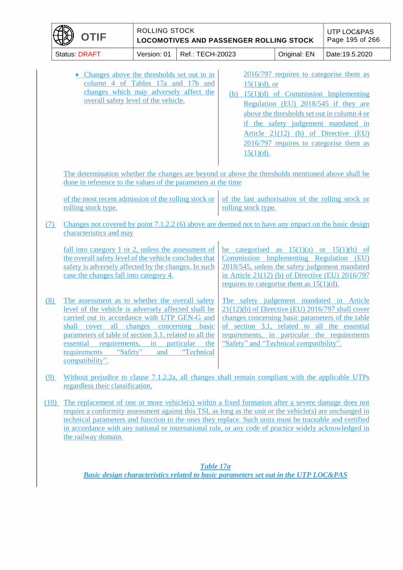
OTIF ROLLING STOCK
LOCOMOTIVES AND PASSENGER ROLLING STOCK
UTP LOC&PAS Page 195 of 266
Status: DRAFT Version: 01 Ref.: TECH-20023 Original: EN Date:19.5.2020
Changes above the thresholds set out in in
column 4 of Tables 17a and 17b and
changes which may adversely affect the
overall safety level of the vehicle.
2016/797 requires to categorise them as
15(1)(d), or
(b) 15(1)(d) of Commission Implementing
Regulation (EU) 2018/545 if they are
above the thresholds set out in column 4 or
if the safety judgement mandated in
Article 21(12) (b) of Directive (EU)
2016/797 requires to categorise them as
15(1)(d).
The determination whether the changes are beyond or above the thresholds mentioned above shall be
done in reference to the values of the parameters at the time
of the most recent admission of the rolling stock or
rolling stock type.
of the last authorisation of the rolling stock or
rolling stock type.
(7) Changes not covered by point 7.1.2.2 (6) above are deemed not to have any impact on the basic design
characteristics and may
fall into category 1 or 2, unless the assessment of
the overall safety level of the vehicle concludes that
safety is adversely affected by the changes. In such
case the changes fall into category 4.
be categorised as 15(1)(a) or 15(1)(b) of
Commission Implementing Regulation (EU)
2018/545, unless the safety judgement mandated
in Article 21(12) (b) of Directive (EU) 2016/797
requires to categorise them as 15(1)(d).
(8) The assessment as to whether the overall safety
level of the vehicle is adversely affected shall be
carried out in accordance with UTP GEN-G and
shall cover all changes concerning basic
parameters of table of section 3.1, related to all the
essential requirements, in particular the
requirements “Safety” and “Technical
compatibility”.
The safety judgement mandated in Article
21(12)(b) of Directive (EU) 2016/797 shall cover
changes concerning basic parameters of the table
of section 3.1, related to all the essential
requirements, in particular the requirements
“Safety” and “Technical compatibility”.
(9) Without prejudice to clause 7.1.2.2a, all changes shall remain compliant with the applicable UTPs
regardless their classification.
(10) The replacement of one or more vehicle(s) within a fixed formation after a severe damage does not
require a conformity assessment against this TSI, as long as the unit or the vehicle(s) are unchanged in
technical parameters and function to the ones they replace. Such units must be traceable and certified
in accordance with any national or international rule, or any code of practice widely acknowledged in
the railway domain.
Table 17a
Basic design characteristics related to basic parameters set out in the UTP LOC&PAS
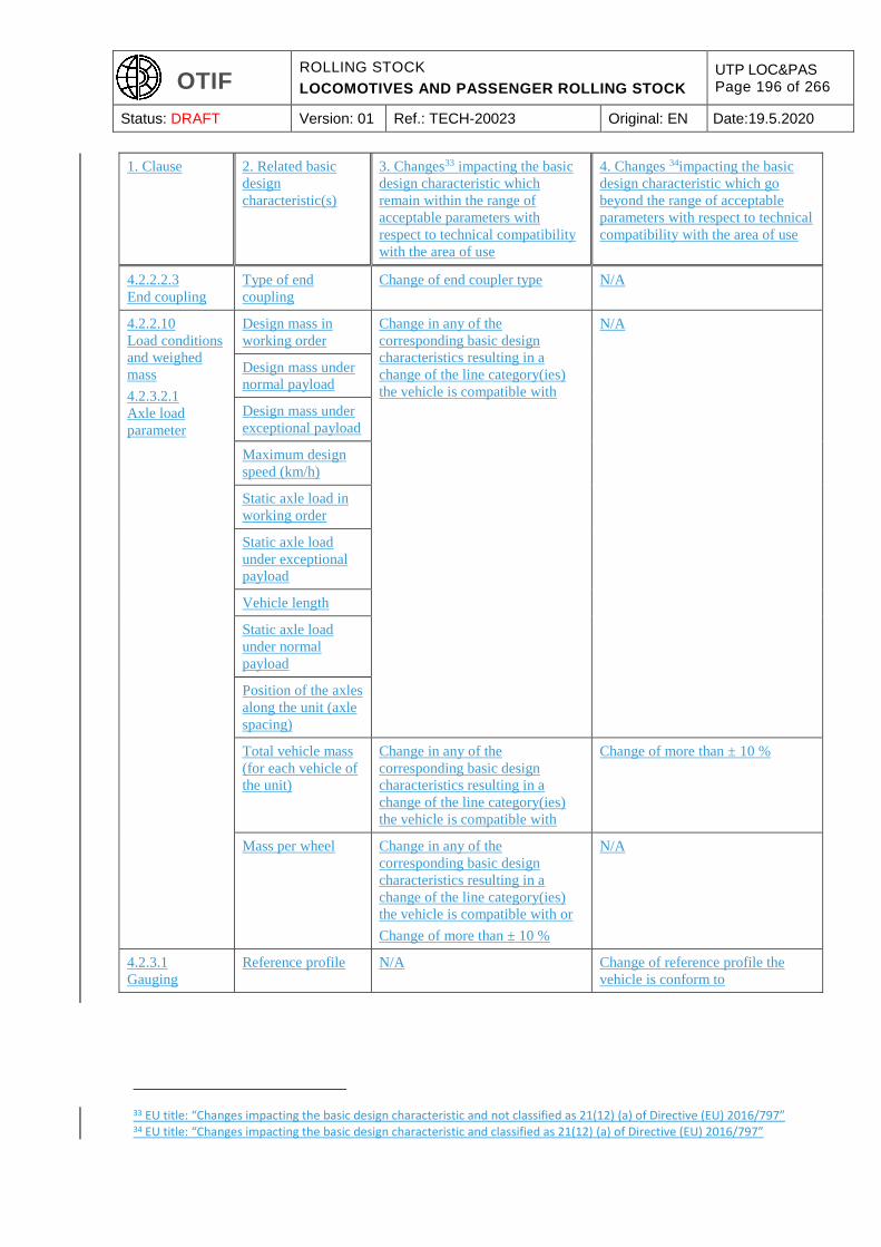
OTIF ROLLING STOCK
LOCOMOTIVES AND PASSENGER ROLLING STOCK
UTP LOC&PAS Page 196 of 266
Status: DRAFT Version: 01 Ref.: TECH-20023 Original: EN Date:19.5.2020
1. Clause 2. Related basic
design
characteristic(s)
3. Changes33 impacting the basic
design characteristic which
remain within the range of
acceptable parameters with
respect to technical compatibility
with the area of use
4. Changes 34impacting the basic
design characteristic which go
beyond the range of acceptable
parameters with respect to technical
compatibility with the area of use
4.2.2.2.3
End coupling
Type of end
coupling
Change of end coupler type N/A
4.2.2.10
Load conditions
and weighed
mass
4.2.3.2.1
Axle load
parameter
Design mass in
working order
Change in any of the
corresponding basic design
characteristics resulting in a
change of the line category(ies)
the vehicle is compatible with
N/A
Design mass under
normal payload
Design mass under
exceptional payload
Maximum design
speed (km/h)
Static axle load in
working order
Static axle load
under exceptional
payload
Vehicle length
Static axle load
under normal
payload
Position of the axles
along the unit (axle
spacing)
Total vehicle mass
(for each vehicle of
the unit)
Change in any of the
corresponding basic design
characteristics resulting in a
change of the line category(ies)
the vehicle is compatible with
Change of more than ± 10 %
Mass per wheel Change in any of the
corresponding basic design
characteristics resulting in a
change of the line category(ies)
the vehicle is compatible with or
Change of more than ± 10 %
N/A
4.2.3.1
Gauging
Reference profile N/A Change of reference profile the
vehicle is conform to
33 EU title: “Changes impacting the basic design characteristic and not classified as 21(12) (a) of Directive (EU) 2016/797” 34 EU title: “Changes impacting the basic design characteristic and classified as 21(12) (a) of Directive (EU) 2016/797”
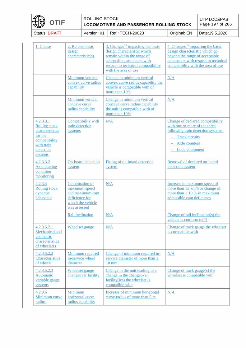
OTIF ROLLING STOCK
LOCOMOTIVES AND PASSENGER ROLLING STOCK
UTP LOC&PAS Page 197 of 266
Status: DRAFT Version: 01 Ref.: TECH-20023 Original: EN Date:19.5.2020
1. Clause 2. Related basic
design
characteristic(s)
3. Changes33 impacting the basic
design characteristic which
remain within the range of
acceptable parameters with
respect to technical compatibility
with the area of use
4. Changes 34impacting the basic
design characteristic which go
beyond the range of acceptable
parameters with respect to technical
compatibility with the area of use
Minimum vertical
convex curve radius
capability
Change in minimum vertical
convex curve radius capability the
vehicle is compatible with of
more than 10%
N/A
Minimum vertical
concave curve
radius capability
Change in minimum vertical
concave curve radius capability
the unit is compatible with of
more than 10%
N/A
4.2.3.3.1
Rolling stock
characteristics
for the
compatibility
with train
detection
systems
Compatibility with
train detection
systems
N/A Change of declared compatibility
with one or more of the three
following train detection systems:
Track circuits
Axle counters
Loop equipment
4.2.3.3.2
Axle bearing
condition
monitoring
On-board detection
system
Fitting of on-board detection
system
Removal of declared on-board
detection system
4.2.3.4
Rolling stock
dynamic
behaviour
Combination of
maximum speed
and maximum cant
deficiency for
which the vehicle
was assessed
N/A Increase in maximum speed of
more than 15 km/h or change of
more than ± 10 % in maximum
admissible cant deficiency
Rail inclination N/A Change of rail inclination(s) the
vehicle is conform to(*)
4.2.3.5.2.1
Mechanical and
geometric
characteristics
of wheelsets
Wheelset gauge N/A Change of track gauge the wheelset
is compatible with
4.2.3.5.2.2
Characteristics
of wheels
Minimum required
in-service wheel
diameter
Change of minimum required in-
service diameter of more than ±
10 mm
N/A
4.2.3.5.2.3
Automatic
variable gauge
systems
Wheelset gauge
changeover facility
Change in the unit leading to a
change in the changeover
facility(ies) the wheelset is
compatible with
Change of track gauge(s) the
wheelset is compatible with
4.2.3.6
Minimum curve
radius
Minimum
horizontal curve
radius capability
Increase of minimum horizontal
curve radius of more than 5 m
N/A
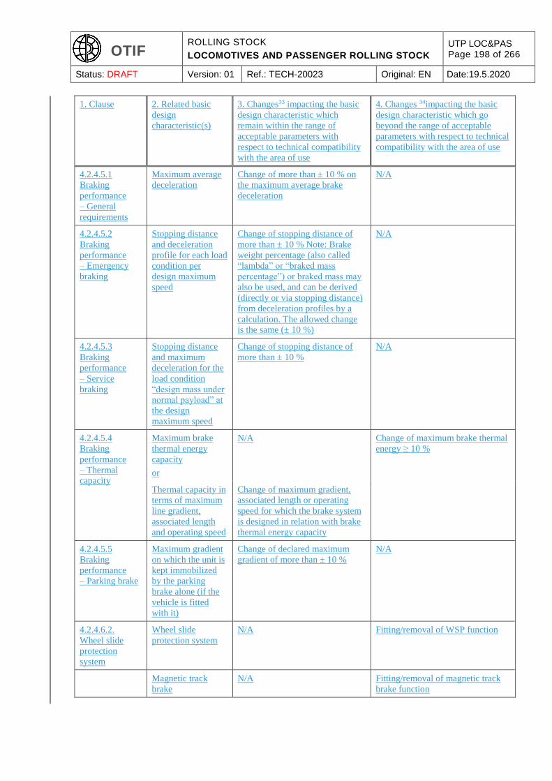
OTIF ROLLING STOCK
LOCOMOTIVES AND PASSENGER ROLLING STOCK
UTP LOC&PAS Page 198 of 266
Status: DRAFT Version: 01 Ref.: TECH-20023 Original: EN Date:19.5.2020
1. Clause 2. Related basic
design
characteristic(s)
3. Changes33 impacting the basic
design characteristic which
remain within the range of
acceptable parameters with
respect to technical compatibility
with the area of use
4. Changes 34impacting the basic
design characteristic which go
beyond the range of acceptable
parameters with respect to technical
compatibility with the area of use
4.2.4.5.1
Braking
performance
– General
requirements
Maximum average
deceleration
Change of more than ± 10 % on
the maximum average brake
deceleration
N/A
4.2.4.5.2
Braking
performance
– Emergency
braking
Stopping distance
and deceleration
profile for each load
condition per
design maximum
speed
Change of stopping distance of
more than ± 10 % Note: Brake
weight percentage (also called
“lambda” or “braked mass
percentage”) or braked mass may
also be used, and can be derived
(directly or via stopping distance)
from deceleration profiles by a
calculation. The allowed change
is the same (± 10 %)
N/A
4.2.4.5.3
Braking
performance
– Service
braking
Stopping distance
and maximum
deceleration for the
load condition
“design mass under
normal payload” at
the design
maximum speed
Change of stopping distance of
more than ± 10 %
N/A
4.2.4.5.4
Braking
performance
– Thermal
capacity
Maximum brake
thermal energy
capacity
or
N/A Change of maximum brake thermal
energy ≥ 10 %
Thermal capacity in
terms of maximum
line gradient,
associated length
and operating speed
Change of maximum gradient,
associated length or operating
speed for which the brake system
is designed in relation with brake
thermal energy capacity
4.2.4.5.5
Braking
performance
– Parking brake
Maximum gradient
on which the unit is
kept immobilized
by the parking
brake alone (if the
vehicle is fitted
with it)
Change of declared maximum
gradient of more than ± 10 %
N/A
4.2.4.6.2.
Wheel slide
protection
system
Wheel slide
protection system
N/A Fitting/removal of WSP function
Magnetic track
brake
N/A Fitting/removal of magnetic track
brake function

OTIF ROLLING STOCK
LOCOMOTIVES AND PASSENGER ROLLING STOCK
UTP LOC&PAS Page 199 of 266
Status: DRAFT Version: 01 Ref.: TECH-20023 Original: EN Date:19.5.2020
1. Clause 2. Related basic
design
characteristic(s)
3. Changes33 impacting the basic
design characteristic which
remain within the range of
acceptable parameters with
respect to technical compatibility
with the area of use
4. Changes 34impacting the basic
design characteristic which go
beyond the range of acceptable
parameters with respect to technical
compatibility with the area of use
4.2.4.8.2
Magnetic track
brake
Possibility of
preventing the use
of the magnetic
track brake
N/A Fitting/removal of the brake control
allowing the activation/deactivation
of magnetic track brake
4.2.4.8.3
Eddy current
track brake
Eddy current track
brake
N/A Fitting/removal of the eddy current
track brake function
Possibility of
preventing the use
of the eddy current
track brake
N/A Fitting/removal of the brake control
allowing the activation/deactivation
of eddy current track brake
4.2.6.1.1
Temperature
Temperature range Change of temperature range (T1,
T2, T3)
N/A
4.2.6.1.2
Snow, ice and
hail
Snow, ice and hail
conditions
Change of the selected range
“snow, ice and hail” (nominal or
severe)
N/A
4.2.8.2.2
Operation
within range of
voltages and
frequencies
Energy supply
system (voltage and
frequency)
N/A Change of voltage(s)/frequency
(ies) of the energy supply system
(AC 25 kV-50 Hz, AC 15 kV-16,7
Hz, DC 3 kV, DC 1,5 kV, DC 750
V, third rail, others)
4.2.8.2.3
Regenerative
brake with
energy to the
overhead
contact line
Regenerative brake N/A Fitting/removal of regenerative
brake function
Possibility of
preventing the use
of the regenerative
brake when fitted
Fitting/removing the possibility of
preventing the use of regenerative
brake
N/A
4.2.8.2.4Maxim
um power and
current from the
overhead
contact line
Applicable to
Electric units with
power higher than 2
MW only:
Power or current
limitation function
Power or current limitation
function fitted/removed
N/A
4.2.8.2.5
Maximum
current at
standstill for DC
systems
Maximum current
at standstill per
pantograph for each
DC system the
vehicle is equipped
for
Change of the maximum current
value by 50 A without exceeding
the limit set in the TSI
N/A
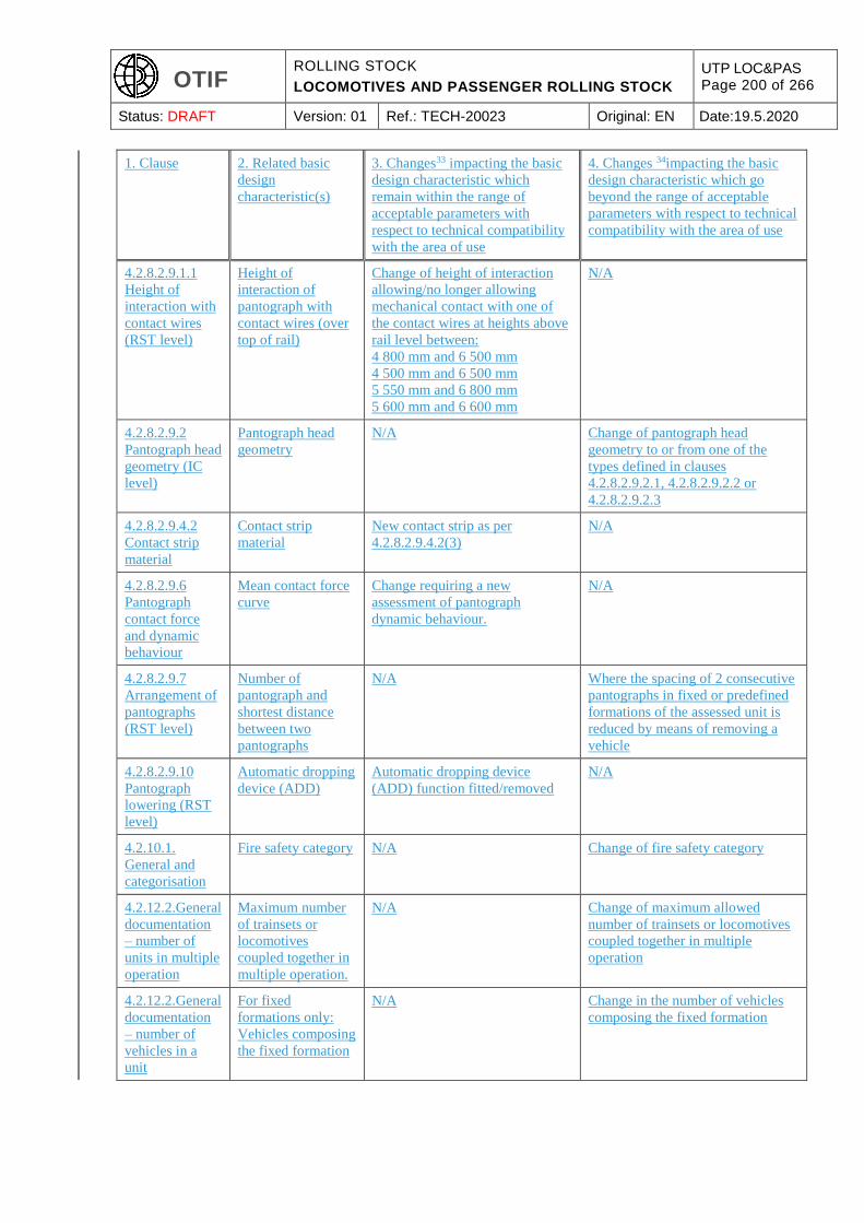
OTIF ROLLING STOCK
LOCOMOTIVES AND PASSENGER ROLLING STOCK
UTP LOC&PAS Page 200 of 266
Status: DRAFT Version: 01 Ref.: TECH-20023 Original: EN Date:19.5.2020
1. Clause 2. Related basic
design
characteristic(s)
3. Changes33 impacting the basic
design characteristic which
remain within the range of
acceptable parameters with
respect to technical compatibility
with the area of use
4. Changes 34impacting the basic
design characteristic which go
beyond the range of acceptable
parameters with respect to technical
compatibility with the area of use
4.2.8.2.9.1.1
Height of
interaction with
contact wires
(RST level)
Height of
interaction of
pantograph with
contact wires (over
top of rail)
Change of height of interaction
allowing/no longer allowing
mechanical contact with one of
the contact wires at heights above
rail level between:
4 800 mm and 6 500 mm
4 500 mm and 6 500 mm
5 550 mm and 6 800 mm
5 600 mm and 6 600 mm
N/A
4.2.8.2.9.2
Pantograph head
geometry (IC
level)
Pantograph head
geometry
N/A Change of pantograph head
geometry to or from one of the
types defined in clauses
4.2.8.2.9.2.1, 4.2.8.2.9.2.2 or
4.2.8.2.9.2.3
4.2.8.2.9.4.2
Contact strip
material
Contact strip
material
New contact strip as per
4.2.8.2.9.4.2(3)
N/A
4.2.8.2.9.6
Pantograph
contact force
and dynamic
behaviour
Mean contact force
curve
Change requiring a new
assessment of pantograph
dynamic behaviour.
N/A
4.2.8.2.9.7
Arrangement of
pantographs
(RST level)
Number of
pantograph and
shortest distance
between two
pantographs
N/A Where the spacing of 2 consecutive
pantographs in fixed or predefined
formations of the assessed unit is
reduced by means of removing a
vehicle
4.2.8.2.9.10
Pantograph
lowering (RST
level)
Automatic dropping
device (ADD)
Automatic dropping device
(ADD) function fitted/removed
N/A
4.2.10.1.
General and
categorisation
Fire safety category N/A Change of fire safety category
4.2.12.2.General
documentation
– number of
units in multiple
operation
Maximum number
of trainsets or
locomotives
coupled together in
multiple operation.
N/A Change of maximum allowed
number of trainsets or locomotives
coupled together in multiple
operation
4.2.12.2.General
documentation
– number of
vehicles in a
unit
For fixed
formations only:
Vehicles composing
the fixed formation
N/A Change in the number of vehicles
composing the fixed formation
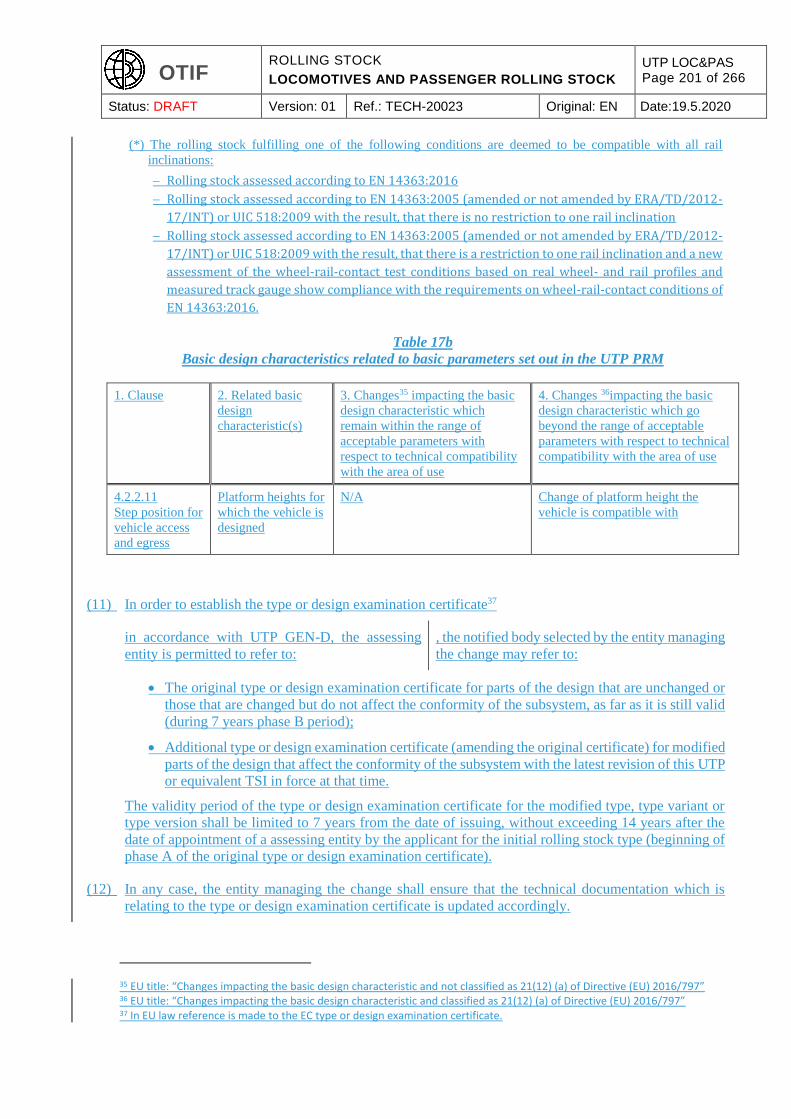
OTIF ROLLING STOCK
LOCOMOTIVES AND PASSENGER ROLLING STOCK
UTP LOC&PAS Page 201 of 266
Status: DRAFT Version: 01 Ref.: TECH-20023 Original: EN Date:19.5.2020
(*) The rolling stock fulfilling one of the following conditions are deemed to be compatible with all rail
inclinations:
Rolling stock assessed according to EN 14363:2016
Rolling stock assessed according to EN 14363:2005 (amended or not amended by ERA/TD/2012-
17/INT) or UIC 518:2009 with the result, that there is no restriction to one rail inclination
Rolling stock assessed according to EN 14363:2005 (amended or not amended by ERA/TD/2012-
17/INT) or UIC 518:2009 with the result, that there is a restriction to one rail inclination and a new
assessment of the wheel-rail-contact test conditions based on real wheel- and rail profiles and
measured track gauge show compliance with the requirements on wheel-rail-contact conditions of
EN 14363:2016.
Table 17b
Basic design characteristics related to basic parameters set out in the UTP PRM
1. Clause 2. Related basic
design
characteristic(s)
3. Changes35 impacting the basic
design characteristic which
remain within the range of
acceptable parameters with
respect to technical compatibility
with the area of use
4. Changes 36impacting the basic
design characteristic which go
beyond the range of acceptable
parameters with respect to technical
compatibility with the area of use
4.2.2.11
Step position for
vehicle access
and egress
Platform heights for
which the vehicle is
designed
N/A Change of platform height the
vehicle is compatible with
(11) In order to establish the type or design examination certificate37
in accordance with UTP GEN-D, the assessing
entity is permitted to refer to:
, the notified body selected by the entity managing
the change may refer to:
The original type or design examination certificate for parts of the design that are unchanged or
those that are changed but do not affect the conformity of the subsystem, as far as it is still valid
(during 7 years phase B period);
Additional type or design examination certificate (amending the original certificate) for modified
parts of the design that affect the conformity of the subsystem with the latest revision of this UTP
or equivalent TSI in force at that time.
The validity period of the type or design examination certificate for the modified type, type variant or
type version shall be limited to 7 years from the date of issuing, without exceeding 14 years after the
date of appointment of a assessing entity by the applicant for the initial rolling stock type (beginning of
phase A of the original type or design examination certificate).
(12) In any case, the entity managing the change shall ensure that the technical documentation which is
relating to the type or design examination certificate is updated accordingly.
35 EU title: “Changes impacting the basic design characteristic and not classified as 21(12) (a) of Directive (EU) 2016/797” 36 EU title: “Changes impacting the basic design characteristic and classified as 21(12) (a) of Directive (EU) 2016/797” 37 In EU law reference is made to the EC type or design examination certificate.
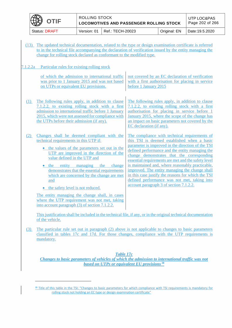
OTIF ROLLING STOCK
LOCOMOTIVES AND PASSENGER ROLLING STOCK
UTP LOC&PAS Page 202 of 266
Status: DRAFT Version: 01 Ref.: TECH-20023 Original: EN Date:19.5.2020
(13) The updated technical documentation, related to the type or design examination certificate is referred
to in the technical file accompanying the declaration of verification issued by the entity managing the
change for rolling stock declared as conformant to the modified type.
7.1.2.2a Particular rules for existing rolling stock
of which the admission to international traffic
was prior to 1 January 2015 and was not based
on UTPs or equivalent EU provisions.
not covered by an EC declaration of verification
with a first authorisation for placing in service
before 1 January 2015
(1) The following rules apply, in addition to clause
7.1.2.2, to existing rolling stock with a first
admission to international traffic before 1 January
2015, which were not assessed for compliance with
the UTPs before their admission (if any).
The following rules apply, in addition to clause
7.1.2.2, to existing rolling stock with a first
authorisation for placing in service before 1
January 2015, where the scope of the change has
an impact on basic parameters not covered by the
EC declaration (if any).
(2) Changes shall be deemed compliant with the
technical requirements in this UTP if:
the values of the parameters set out in the
UTP are improved in the direction of the
value defined in the UTP and
the entity managing the change
demonstrates that the essential requirements
which are concerned by the change are met
and
the safety level is not reduced.
The entity managing the change shall, in cases
where the UTP requirement was not met, taking
into account paragraph (3) of section 7.1.2.2.
The compliance with technical requirements of
this TSI is deemed established when a basic
parameter is improved in the direction of the TSI
defined performance and the entity managing the
change demonstrates that the corresponding
essential requirements are met and the safety level
is maintained and, where reasonably practicable,
improved. The entity managing the change shall
in this case justify the reasons for which the TSI
defined performance was not met, taking into
account paragraph 3 of section 7.1.2.2.
This justification shall be included in the technical file, if any, or in the original technical documentation
of the vehicle.
(3) The particular rule set out in paragraph (2) above is not applicable to changes to basic parameters
classified in tables 17c and 17d. For those changes, compliance with the UTP requirements is
mandatory.
Table 17c
Changes to basic parameters of vehicles of which the admission to international traffic was not
based on UTPs or equivalent EU provisions 38
38 Title of this table in the TSI: “Changes to basic parameters for which compliance with TSI requirements is mandatory for rolling stock not holding an EC type or design examination certificate”
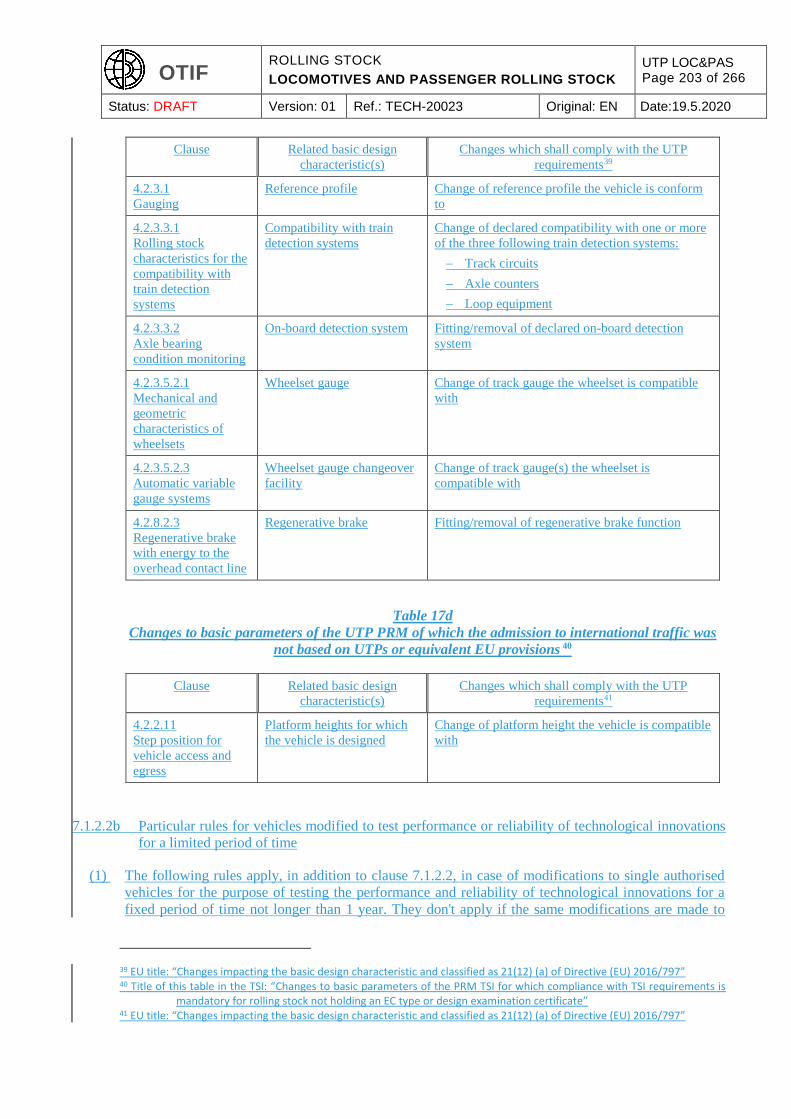
OTIF ROLLING STOCK
LOCOMOTIVES AND PASSENGER ROLLING STOCK
UTP LOC&PAS Page 203 of 266
Status: DRAFT Version: 01 Ref.: TECH-20023 Original: EN Date:19.5.2020
Clause Related basic design
characteristic(s)
Changes which shall comply with the UTP
requirements39
4.2.3.1
Gauging
Reference profile Change of reference profile the vehicle is conform
to
4.2.3.3.1
Rolling stock
characteristics for the
compatibility with
train detection
systems
Compatibility with train
detection systems
Change of declared compatibility with one or more
of the three following train detection systems:
Track circuits
Axle counters
Loop equipment
4.2.3.3.2
Axle bearing
condition monitoring
On-board detection system Fitting/removal of declared on-board detection
system
4.2.3.5.2.1
Mechanical and
geometric
characteristics of
wheelsets
Wheelset gauge Change of track gauge the wheelset is compatible
with
4.2.3.5.2.3
Automatic variable
gauge systems
Wheelset gauge changeover
facility
Change of track gauge(s) the wheelset is
compatible with
4.2.8.2.3
Regenerative brake
with energy to the
overhead contact line
Regenerative brake Fitting/removal of regenerative brake function
Table 17d
Changes to basic parameters of the UTP PRM of which the admission to international traffic was
not based on UTPs or equivalent EU provisions 40
Clause Related basic design
characteristic(s)
Changes which shall comply with the UTP
requirements41
4.2.2.11
Step position for
vehicle access and
egress
Platform heights for which
the vehicle is designed
Change of platform height the vehicle is compatible
with
7.1.2.2b Particular rules for vehicles modified to test performance or reliability of technological innovations
for a limited period of time
(1) The following rules apply, in addition to clause 7.1.2.2, in case of modifications to single authorised
vehicles for the purpose of testing the performance and reliability of technological innovations for a
fixed period of time not longer than 1 year. They don't apply if the same modifications are made to
39 EU title: “Changes impacting the basic design characteristic and classified as 21(12) (a) of Directive (EU) 2016/797” 40 Title of this table in the TSI: “Changes to basic parameters of the PRM TSI for which compliance with TSI requirements is
mandatory for rolling stock not holding an EC type or design examination certificate” 41 EU title: “Changes impacting the basic design characteristic and classified as 21(12) (a) of Directive (EU) 2016/797”

OTIF ROLLING STOCK
LOCOMOTIVES AND PASSENGER ROLLING STOCK
UTP LOC&PAS Page 204 of 266
Status: DRAFT Version: 01 Ref.: TECH-20023 Original: EN Date:19.5.2020
several vehicles.
(2) The compliance with technical requirements of this UTP is deemed established when a basic parameter
is kept unchanged or improved in the direction of the UTP defined performance and the entity managing
the change demonstrates that the corresponding essential requirements are met and the safety level is
maintained and, where reasonably practicable, improved.
7.1.2.3. Upgrade
The Contracting State The Member State
shall use the following principles as a basis for determining the application of this
UTP TSI
in case of upgrade:
(1) Parts and basic parameters of the subsystem that have not been affected by the upgrading works
are exempt from conformity assessment against the provisions in this
UTP. TSI.
(2) A new assessment against the requirements of this
UTP TSI
is only needed for the basic parameters in this
UTP TSI
which have their performance influenced by the modification(s).
(3) When during the upgrade it is not economically feasible to fulfil the
UTP TSI
requirement, the upgrade could be accepted if it is evident that a basic parameter is improved
in the direction of the
UTP TSI
defined performance.
In such a case the admission to
international traffic of the unit shall be
reconsidered by the application of ATMF
Article 6 § 4.
(4) Guidance to the
Contracting State Member State
for those modifications that are deemed to be upgrades is given in the application guide.
OTIF ROLLING STOCK
LOCOMOTIVES AND PASSENGER ROLLING STOCK
UTP LOC&PAS Page 205 of 266
Status: DRAFT Version: 01 Ref.: TECH-20023 Original: EN Date:19.5.2020
(5) National migration strategies related to the
implementation of other TSI (e.g. TSI covering
fixed installations) may have an impact to what
extent this TSI needs to be applied.
(6) For a project including elements not being
UTP TSI
conform, the procedures for the assessment of conformity and
UTP EC
verification to be applied should be agreed with the
Contracting States concerned.
In such a case the admission to
international traffic of the unit shall be
reconsidered by the application of ATMF
Article 6 § 4.
Member State.
7.1.3. Rules related to the type or design examination certificates42
7.1.3.1. Rolling stock subsystem
(1) This clause concerns a rolling stock type (unit type in the context of this
UTP), TSI),
as defined in
Article 2(w) of ATMF, Article 2(w) of Directive 2008/57/EC,
which is subject to a
EC
type or design verification procedure in accordance with the section 6.2 of this
UTP. TSI.
(2) The
UTP TSI
assessment basis for a ‘type or design examination’ is defined in columns 2 and 3 (design and
development phase) of Appendix H of this
UTP. TSI.
42 In EU law reference is made to the EC type or design examination certificate.
OTIF ROLLING STOCK
LOCOMOTIVES AND PASSENGER ROLLING STOCK
UTP LOC&PAS Page 206 of 266
Status: DRAFT Version: 01 Ref.: TECH-20023 Original: EN Date:19.5.2020
(1) This point concerns the procedure referred to in
Article 10 of ATMF according to which a Design
Type Certificate related to a vehicle type and a
Certificate of Operation related to a vehicle are
granted.
This clause concerns a rolling stock type (unit
type in the context of this TSI), as defined in
Article 2(26) of Directive (EU) 2016/797, which
is subject to a EC type or design verification
procedure in accordance with the section 6.2 of
this TSI. It also applies to the EC type or design
verification procedure in accordance with the TSI
Noise (Commission Regulation (EU) No
1304/2014), and the TSI PRM (Commission
Regulation (EU) No 1300/2014) which refers to
this TSI for its scope of application to
Locomotives and Passenger rolling Stock.
(2) The basis of assessment is defined in columns 2
and 3 ‘Design review’ and ‘Type test’ of
Appendix H of this UTP.
The TSI assessment basis for a “EC type or design
examination” is defined in columns 2 and 3
“Design review” and “Type test” of Appendix H
of this TSI.
Phase A
(3) Phase A starts at the moment an assessing entity is
appointed (in case of private entity) or involved
(in case of public entity) and ends when the
Design Type Certificate is issued.
Phase A starts once a notified body, which is
responsible for EC verification, is appointed by
the applicant and ends when the EC type or design
examination certificate is issued.
(4) The assessment basis for a type is defined for a
phase A period, with a duration of maximum
seven years. During phase A, the applicable
technical requirements shall not change, without
prejudice to clauses 7.1.14 and 7.1.1.8 and point 5
below.
The TSI assessment basis for a type is defined for
a phase A period, with a duration of maximum
seven years. Without prejudice to clauses 7.1.1.4
to 7.1.1.8, during the phase A period the
assessment basis for EC verification to be used by
the notified body will not change.
(5) When a revision of this UTP or of the UTP Noise or UTP PRM comes into force during the phase A
period, it is permissible (but not mandatory) to use the revised version, either totally or for particular
sections, unless explicitly otherwise specified in the revision of these UTPs; in case of application
limited to particular sections, the applicant has to justify and document that applicable requirements
remain consistent, and this has to be approved by the Competent Authority.
(3) Phase A starts once
an assessing entity a notified body
which is responsible for
EC
verification, is appointed by the applicant and ends when the
EC
OTIF ROLLING STOCK
LOCOMOTIVES AND PASSENGER ROLLING STOCK
UTP LOC&PAS Page 207 of 266
Status: DRAFT Version: 01 Ref.: TECH-20023 Original: EN Date:19.5.2020
type examination certificate is issued.
(4) The UTP The TSI
assessment basis for a type is defined for a phase A period, with a duration of maximum seven
years. During the phase A period the assessment basis for
EC
verification to be used by the
assessing entity notified body
will not change.
(5) When a revised version of this
UTP TSI
comes into force during the phase A period, it is permissible (but not mandatory) to use the
revised version, either totally or for particular sections; in case of application limited to
particular sections, the applicant has to justify and document that applicable requirements
remain consistent, and this has to be approved by the
assessing entity. notified body.
Phase B
(6) Phase B starts at the moment the Design Type
Certificate is issued by the competent authority.
During the Phase B period, Certificates of
Operation may be issued for vehicles complying
with the Design Type Certificate.
The phase B period defines the period of validity
of the EC type or design examination certificate
once it is issued by the notified body. During this
time, units may be EC certified on the basis of
conformity to type.
(7) The Design Type Certificate is valid for seven
year following the date it was issued.
Modifications to this UTP or the UTP Noise or
the UTP PRM shall not apply during the Phase B
period, unless specified otherwise in these revised
UTPs.
The EC type or design examination certificate of
EC verification for the subsystem is valid for a
seven year phase B period after its issue date, even
if a revision of this TSI or of the TSI Noise or the
TSI PRM comes into force, unless explicitly
otherwise specified in the revision of these TSIs.
During this period of validity, new rolling stock
of the same type is permitted to be placed on the
market on the basis of an EC declaration of
verification referring to the type certificate of
verification.
(6) The phase B period defines the period of validity of the type examination certificate once it is
issued by the
assessing entity. notified body.
OTIF ROLLING STOCK
LOCOMOTIVES AND PASSENGER ROLLING STOCK
UTP LOC&PAS Page 208 of 266
Status: DRAFT Version: 01 Ref.: TECH-20023 Original: EN Date:19.5.2020
During this time, units may be
UTP EC
certified on the basis of conformity to type.
(7) The type examination certificate of
UTP EC
verification for the subsystem is valid for a seven year phase B period after its issue date, even
if a revision of this
UTP TSI
comes into force. During this time, new rolling stock of the same type is permitted to be placed
in service on the basis of an
UTP EC
declaration of verification referring to the type certificate of verification.
Modifications to a type or design already bearing an
UTP EC
certificate of verification
(8) For modifications to a rolling stock type already bearing a type or design examination
certificate of verification, the following rules apply:
The changes are permitted to be dealt with by only re-assessing those modifications
which influence the basic parameters of the latest revision of this
UTP TSI
in force at that time.
In order to establish the certificate of
UTP verification, the assessing
entity
EC verification, the notified body
is permitted to refer to:
The original type or design examination certificate for parts of the design that are
unchanged, as far as it is still valid (during 7 years phase B period).
Additional type or design examination certificate (amending the original certificate) for
modified parts of the design which influence the basic parameters of the latest
revision of this
UTP TSI
in force at that time.

OTIF ROLLING STOCK
LOCOMOTIVES AND PASSENGER ROLLING STOCK
UTP LOC&PAS Page 209 of 266
Status: DRAFT Version: 01 Ref.: TECH-20023 Original: EN Date:19.5.2020
7.1.3.2. Interoperability constituents
(1) This clause concerns an interoperability constituent which is subject to type examination (module CB)
or to suitability for use (module CV).
This clause only applies for ICs which are assessed
separately from the subsystem.
(2) The type or design examination or suitability for use certificate is valid for a five year period. During
this time, new constituents of the same type are permitted to be placed into service without a new type
assessment. Before the end of the five-year period, the constituent shall be assessed according to the
latest revision of this
UTP TSI
in force at that time, for those requirements that have changed or are new in comparison to the
certification basis.
7.1.4. Rules for the extension of the area of use for existing rolling stock having an authorisation in
accordance with Directive 2008/57/EC or in operation before 19 July 2010
(1) This clause sets out rules for the extension of the
area of use of existing rolling stock which is not in
full compliance with this UTP.
In accordance with Article 10 § 4 of ATMF, where
the applicant wishes to extend the area of use of a
vehicle which has already been admitted to
operation, it shall update the vehicle’s
documentation concerning this additional area of
use and apply for the process defined in Article 6 §
4 of ATMF.
In the absence of full conformity with this TSI,
point 2 applies to rolling stock that fulfils the
following conditions when requesting the
extension of its area of use in accordance with
Article 21(13) of Directive (EU) 2016/797:
a) it has been authorised in accordance with
Directive 2008/57/EC or put in operation
before 19 July 2010;
b) it is registered with “Valid” registration
code “00”, in the National Vehicle
Register in accordance with Commission
Decision 2007/756/EC43 or in the
European Vehicle Register in accordance
with Commission Implementing Decision
(EU) 2018/161444 and maintained in a
safe state of running in accordance with
Commission Implementing Regulation
(EU) 2019/77945.
43 Commission Decision 2007/756/EC of 9 November 2007 adopting a common specification of the national vehicle register provided for under Articles 14(4) and (5) of Directives 96/48/EC and 2001/16/EC (OJ L 305, 23.11.2007, p. 30)
44 Commission Implementing Decision (EU) 2018/1614 of 25 October 2018 laying down specifications for the vehicle registers referred to in Article 47 of Directive (EU) 2016/797 of the European Parliament and of the Council and amending and repealing Commission Decision 2007/756/EC (OJ L 268, 26.10.2018, p. 53)
45 Commission Implementing Regulation (EU) 2019/779 of 16 May 2019 laying down detailed provisions on a system of certification of entities in charge of maintenance of vehicles pursuant to Directive (EU) 2016/798 of the European Parliament and of the Council and repealing Commission Regulation (EU) No 445/2011 (OJ L 139 I, 27.5.2019, p. 360)
OTIF ROLLING STOCK
LOCOMOTIVES AND PASSENGER ROLLING STOCK
UTP LOC&PAS Page 210 of 266
Status: DRAFT Version: 01 Ref.: TECH-20023 Original: EN Date:19.5.2020
The following provisions for extension of area of
use apply also in combination with a new
authorisation as defined in point (a) of Article
14(3) of Regulation (EU) 2018/545.
(2) Extending the area of use of the rolling stock
referred to in point 1 by complementary vehicle
admission shall be based on the existing admission,
if any, and on the technical compatibility between
the rolling stock and the network(s) of the state(s)
concerned and compliance with the Basic Design
Characteristics of Table 17a and 17b of this UTP,
taking into account any restrictions or limitations.
The applicant shall provide the Competent
Authority with the technical certificates defined in
Article 11 of ATMF, including all attachments and
any other evidence of compliance with the
requirements set out in this UTP
Authorisation for an extended area of use of the
rolling stock referred to in point 1 shall be based
on the existing authorisation, if any, and on the
technical compatibility between the rolling stock
and the network in accordance with point (d) of
Article 21(3) of Directive (EU) 2016/797 and
compliance with the Basic Design Characteristics
of Table 17a and 17b of this TSI, taking into
account any restrictions or limitations.
The applicant shall provide an ‘EC’ declaration
of verification’ accompanied by technical files
giving evidence of compliance with the
requirements set out in this TSI,
or with provisions having equivalent effect, for each basic parameter referred to in column 1 of Tables
17a and 17b and with the following clauses of this UTP:
4.2.4.2.2, 4.2.5.5.8, 4.2.5.5.9, 4.2.6.2.3, 4.2.6.2.4, 4.2.6.2.5, 4.2.8.2.7, 4.2.8.2.9.8 (when running
through phase or system separation sections is managed automatically), 4.2.9.3.1, 4.2.9.6, 4.2.12
and 4.2.12.6
4.2.5.3 in Italy
4.2.5.3.5 and 4.2.9.2.1 in Germany
through one or a combination of the following:
a) compliance with requirements set out in this UTP as referred above;
b) compliance with corresponding requirements set out in a previous UTP as referred above;
c) compliance with alternative specifications deemed to have equivalent effect to the relevant
requirements set out in this UTP as referred above;
d) evidence that the requirements for technical compatibility with the network of the extended area
of use are equivalent to the requirements for technical compatibility with the network for which
the rolling stock is already admitted or in operation. Such evidence shall be provided by the
applicant and may be based on the information of the register of railway infrastructure (RINF).
(3) The equivalent effect of alternative specifications to the requirements of this UTP (point 2(c)) and the
equivalence of requirements for technical compatibility with the network (point 2(d)) shall be justified
and documented by the applicant by applying the risk management process set out in Annex I of UTP
GEN-G. The justification has to be assessed and confirmed by an assessment body (CSM RA).
(4) In addition to the requirements mentioned referred to in point 2 and where applicable, the applicant
shall provide
an ‘EC’ declaration of verification accompanied
by technical files giving
OTIF ROLLING STOCK
LOCOMOTIVES AND PASSENGER ROLLING STOCK
UTP LOC&PAS Page 211 of 266
Status: DRAFT Version: 01 Ref.: TECH-20023 Original: EN Date:19.5.2020
evidence of compliance with the following:
a) specific cases relating to any part of the extended area of use, listed in this TSI, the TSI Noise
(Regulation (EU) No 1304/2014), the TSI PRM (Regulation (EU) No 1300/2014) and CCS TSI
(Regulation (EU) 2016/919);
b) the national rules referred to in points (a), (c) and (d) of Article 13(2) of Directive (EU) 2016/797
as notified in accordance with Article 14 of that Directive.
(5) (reserved) The authorising entity shall make publicly
available through the Agency website details of
the alternative specifications referred to in point
2 (c) and of the requirements for technical
compatibility with the network referred to in
point 2 (d) on the basis of which it granted
authorisations for the extended area of use.
(6) (reserved) Where an authorised vehicle benefited from non-
application of TSIs or part of them pursuant to
Article 9 of Directive 2008/57/EC, the applicant
shall seek derogation(s) in the Member States of
the extended area of use in accordance to Article
7 of Directive (EU) 2016/797.
(7) Article 19 of ATMF lays down transitional
provisions for vehicles admitted to operation before
1 January 2011 which are marker RIC.
In accordance with Article 54(2) of Directive
(EU) 2016/797, coaches used under Regolamento
Internazionale Carrozze (RIC) shall be deemed
authorised in accordance with the conditions
under which they were used, including the area of
use where they are operated. Following a change
which requires a new authorisation for placing on
the market in accordance with Article 21(12) of
Directive (EU) 2016/797, coaches accepted under
the latest RIC agreement shall conserve the area
of use in which they were operating without
further checks on the unchanged parts.
7.2. Compatibility with other subsystems
(1) This
UTP TSI
has been developed with consideration of other subsystems being compliant
with harmonised provisions developed in the
European Union, which at the time of drafting have
no mandatory equivalence at international level
outside the EU.
to their respective TSI.
Accordingly, interfaces with the fixed
installations infrastructure, energy and control-
command subsystems are addressed for
subsystems compliant with the Infrastructure TSI,
the Energy TSI and the CCS TSI.
OTIF ROLLING STOCK
LOCOMOTIVES AND PASSENGER ROLLING STOCK
UTP LOC&PAS Page 212 of 266
Status: DRAFT Version: 01 Ref.: TECH-20023 Original: EN Date:19.5.2020
(2) Following this, the implementation methods and phases concerning rolling stock depend on the progress
of implementation of the
compatible infrastructure, in line with UTPs
developed and applied for the subsystems which
constitute the fixed installations of the rail system.
Infrastructure TSI, the Energy TSI and the CCS
TSI.
(3) The compatibly between rolling stock and fixed
installations should be verified before using a
vehicle on a particular line. This is the
responsibility of the railway undertaking.
However, the railway undertaking must be able to
rely on information provided to it from other
entities, in particular the infrastructure manager.
Furthermore, TSI, covering the fixed installations
allow for a set of different technical
characteristics (e.g. “traffic code” in INF TSI,
“power supply system” in ENE TSI).
(4) For rolling stock, the corresponding technical
characteristics are recorded in the “European
register of authorised types of vehicles”,
according to Article 34 48 of Directive (EU)
2016/7972008/57/EC and Commission
Implementing Decision 2011/665/EU of 4
October 2011 on the European register of
authorised types of vehicles (see also section 4.8
of this TSI).
(5) For fixed installations, they are part of the main
features recorded in the “Register of
infrastructure”, according to Article 35 48 of
Directive (EU) 2016/7972008/57/EC and
Commission Implementing Decision
2019/777462011/633/EU on the common
specification of the register of railway
infrastructure.
7.3. Specific cases
7.3.1. General
(1) The specific cases, as listed in the following clause, describe special provisions that are needed and
authorised on particular networks of each
Contracting State.
The specific cases for Member States of the
European Union are those which are included in the
TSI LOC&PAS.
Specific cases for Norway are those applicable for
the LOC&PAS TSI as set out in Article 1(2) points
Member State.
46 Commission Implementing Regulation (EU) 2019/777 of 16 May 2019 on the common specifications for the register of railway infrastructure and repealing Implementing Decision 2014/880/EU [RINF] (OJ L 139 I, 27.5.2019, p. 312).
OTIF ROLLING STOCK
LOCOMOTIVES AND PASSENGER ROLLING STOCK
UTP LOC&PAS Page 213 of 266
Status: DRAFT Version: 01 Ref.: TECH-20023 Original: EN Date:19.5.2020
(a) to (f) of the Decision of the EEA Joint
Committee No 176/2012 of 28 September 2012
amending Annex XIII (Transport) to the EEA
Agreement as published in the Official Journal of
the European Union L 341, 13.12.2012, p. 29.
(2) These specific cases are classified as:
“P” cases: “permanent” cases.
“T” cases: “temporary” cases, where it is planned that the target system is reached in the future.
“T0”: “temporary” cases of indefinite duration, where the target system shall be reached by a
date still to be determined.
“T1” cases: “temporary” cases, where the target system shall be reached by 31 December 2025.
“T2” cases: “temporary” cases, where the target system shall be reached by 31 December 2035.
All specific cases and their relevant dates shall be
re-examined in the course of future revisions of
the TSI with a view to limiting their technical and
geographical scope based on an assessment of
their impact on safety, interoperability, cross
border services, TEN-T corridors, and the
practical and economic impacts of retaining or
eliminating them. Special account shall be given
to availability of EU funding.
Specific cases shall be limited to the route or
network where they are strictly necessary and
taken account of through route compatibility
procedures.
(3) Any specific case applicable to the rolling stock in the scope of this
UTP TSI
shall be addressed in this
UTP. TSI.
(4) Certain specific cases are in interface to other
UTP. TSI.
Where a clause in this
UTP TSI
refers to another
UTP TSI
OTIF ROLLING STOCK
LOCOMOTIVES AND PASSENGER ROLLING STOCK
UTP LOC&PAS Page 214 of 266
Status: DRAFT Version: 01 Ref.: TECH-20023 Original: EN Date:19.5.2020
to which a specific case is applicable, or where a specific case is applicable to the rolling stock as a
consequence of a specific case declared in another
UTP, TSI,
these are also described in this
UTP. TSI.
(5) Moreover, some specific cases do not prevent the access to the national network to
UTP TSI
compliant rolling stock. In that case, it is explicitly stated in the concerned section of the clause 7.3.2
below.
(6) In case of a specific case applicable to a component defined as interoperability constituent in section
5.3 of this UTP, the conformity assessment has to be made according to the clause 6.1.1 point (3).
7.3.2. List of specific cases
This section only covers specific cases which are
not included in the LOC&PAS TSI.
7.3.2.1. Maximum pressure variations in tunnels (4.2.6.2.3)
Specific Case Switzerland (“P”)
Maximum pressure variations in tunnels:
Vehicles for passenger service designed to operate at speed higher than 160 km/h and intended to be
used in long single-track tunnels constructed with a cross-section of 41 m2 shall be verified by means
of a test run.
The requirements applicable for this specific case shall be forwarded to the CTE by Switzerland
according to the results of the type test runs scheduled in 2015 in the Gotthard base tunnel.
Consecutively this UTP will be updated as necessary.
If the vehicle does not fulfil these requirements, operating rules (e.g. speed restrictions) may apply.
7.3.2.2. Pantograph head geometry (IC level) (4.2.8.2.9.2)
Specific Case Switzerland (“P”)
For operation on existing lines the electric units have to be equipped with a pantograph having a head
geometry length of 1450 mm, unless specified otherwise in the infrastructure register. (EN 50367:2012
Annex B2, Figure B.1)
7.3.2.3. Pantograph contact force and dynamic behaviour (4.2.8.2.9.6)
Specific Case Switzerland (“P”)
OTIF ROLLING STOCK
LOCOMOTIVES AND PASSENGER ROLLING STOCK
UTP LOC&PAS Page 215 of 266
Status: DRAFT Version: 01 Ref.: TECH-20023 Original: EN Date:19.5.2020
For operation on existing lines requiring a head geometry length of 1450 mm, the pantograph and
overhead contact lines must work properly together in all operating configurations and at the speed
range used. (EN 50367:2012, Annex B, table B.1 and table B.5 and fig. B.1; Annex C, table C.1)
7.4. Specific environmental conditions
Specific conditions Austria
Unrestricted access in Austria under winter conditions is granted if the following conditions are met:
The additional capability of the obstacle deflector to remove snow as specified for snow, ice and
hail severe conditions in clause 4.2.6.1.2 shall be provided.
Locomotives and power head units shall be provided with sanding devices.
Specific conditions Estonia
For unrestricted access of rolling stock on the Estonia network under winter conditions, it shall be
demonstrated that the rolling stock meets the following requirements:
Temperature zone T2 as specified in clause 4.2.6.1.2 shall be selected.
Snow, ice and hail severe conditions as specified in clause 4.2.6.1.2, excluding the scenario
‘Snowdrift’ shall be selected.
Specific conditions Finland
For unrestricted access of rolling stock on the Finnish network under winter conditions, it shall be
demonstrated that the rolling stock meets the following requirements:
Temperature zone T2 as specified in clause 4.2.6.1.1 shall be selected
Snow, ice and hail severe conditions as specified in clause 4.2.6.1.2, excluding the scenario
“Snowdrift” shall be selected
Regarding the braking system, unrestricted access in Finland under winter conditions is granted
if the following conditions are met:
at least half of the bogies are equipped with a magnetic track brake for trainset or passenger
coach of nominal speed exceeding 140 km/h.
all bogies are equipped with a magnetic track brake for trainset or passenger coach of nominal
speed exceeding 180 km/h.
Specific conditions France
Unrestricted access in France under winter conditions is granted if the following condition is met:
locomotives and power head units shall be provided with sanding devices.
Specific conditions Greece
For unrestricted access to the Greek network under summer conditions, temperature zone T3 as
specified in clause 4.2.6.1.1 shall be selected.
OTIF ROLLING STOCK
LOCOMOTIVES AND PASSENGER ROLLING STOCK
UTP LOC&PAS Page 216 of 266
Status: DRAFT Version: 01 Ref.: TECH-20023 Original: EN Date:19.5.2020
Specific conditions Germany
Unrestricted access in Germany under winter conditions, is granted if the following condition is met:
locomotives and power head units shall be provided with sanding devices.
Specific conditions Portugal
For unrestricted access to the Portuguese network under summer conditions, temperature zone T3 as
specified in clause 4.2.6.1.1 shall be selected.
Specific conditions Spain
For unrestricted access to the Spanish network under summer conditions, temperature zone T3 as
specified in clause 4.2.6.1.1 shall be selected.
Specific conditions Sweden
For unrestricted access of rolling stock on the Swedish network under winter conditions, it shall be
demonstrated that the rolling stock meets the following requirements:
Temperature zone T2 as specified in clause 4.2.6.1.1 shall be selected
Snow, ice and hail severe conditions as specified in clause 4.2.6.1.2 shall be selected
Specific conditions Switzerland
For unrestricted access in Switzerland under winter
conditions the additional capability of the obstacle
deflector to remove snow as specified for snow, ice
and hail severe conditions in clause 4.2.6.1.2 shall
be provided.
7.5. Aspects that have to be considered in the revision process
or in other activities of the Agency
The EU has identified aspects of interest for the
future development of the EU railway system
Further to the analysis performed during the
drafting process of this TSI, particular aspects
have being identified as of interest for the future
development of the EU railway system
These aspects are of 3 different groups:
(1) Those already subject of a basic parameter in this
UTP, TSI,
with a possible evolution of the corresponding specification when the
UTP TSI
will be revised.
OTIF ROLLING STOCK
LOCOMOTIVES AND PASSENGER ROLLING STOCK
UTP LOC&PAS Page 217 of 266
Status: DRAFT Version: 01 Ref.: TECH-20023 Original: EN Date:19.5.2020
(2) Those not considered in the current state of the art as basic parameter, but which are subject to research
projects.
(3) Those relevant in the framework of on-going studies related to the
EU
railway system, which are not in the scope of
UTP. TSI.
These aspects are identified below, classified according to the breakdown of the clause 4.2 of the
UTPTSI.
7.5.1. Aspects related to a basic parameter in this
UTP TSI
7.5.1.1. Axle load parameter (clause 4.2.3.2.1)
This basic parameter covers the interface between infrastructure and rolling stock regarding the vertical
load.
In the EU, According to the INF TSI,
the lines are classified as specified in the standard EN 15528:2008. This standard specifies also a
categorization of railway vehicles, for freight wagons and particular types of locomotives and passenger
vehicles; it will be revised to cover all types of rolling stock, and to cover HS lines.
When this revision will be available, it may be of interest to include in the
UTP certificate issued by the assessing entity EC certificate delivered by the notified body
the “design” classification of the unit under assessment:
Classification corresponding to the design mass under normal payload.
Classification corresponding to the design mass under exceptional payload.
This aspect will have to be considered when revising this
UTP, TSI,
which already requires in its present version to record all data necessary to determine these
classifications.
It has to be noted that the requirement to the railway undertaking to define and control the operational
load,
as specified in the clause 4.2.2.5 of the OPE TSI
will remain unchanged.

OTIF ROLLING STOCK
LOCOMOTIVES AND PASSENGER ROLLING STOCK
UTP LOC&PAS Page 218 of 266
Status: DRAFT Version: 01 Ref.: TECH-20023 Original: EN Date:19.5.2020
7.5.1.2. Aerodynamic effects - Cross wind (clause 4.2.6.2.4)
Requirements on “cross wind” have been set up for units of maximum design speed equal to or higher
than 250 km/h
with 2 options:
in consistency with the HS RST TSI
or
in consistency with the CR LOC&PAS
TSI.
This will need to be reviewed when the merging of the 2 sets of characteristics wind curves
specified in the HS RST TSI
will be finalised.
7.5.1.3. Aerodynamic effects on ballasted tracks (clause 4.2.6.2.5)
Requirements on aerodynamic effects on ballasted tracks have been set up for units of maximum design
speed higher than 250 km/h.
As the current state of the art does not allow to provide for a harmonized requirement nor assessment
methodology, the UTP allows the application of national rules.
This will need to be reviewed in order to consider the following:
Study of ballast-pick-up occurrences, and corresponding safety impact (if any)
Development of a harmonized, cost-effective methodology applicable in EU.
7.5.2. Aspects not related to a basic parameter in this
UTP TSI
but subject to research projects
7.5.2.1. Additional requirements for security reasons
The interior of vehicles interfacing with passengers and train crew should provide protection of the
occupants in the event of a collision by providing means of:
minimising the risk of injury due to secondary impact with such furniture and interior fixtures
and fittings
minimising those injuries that may preclude subsequent escape
Some EU research projects have been launched in 2006 to study the consequence of railway accidents
(collision, derailment…) on passengers, to evaluate in particular the risk and level of injuries; the
objective is to define requirements and corresponding conformity assessment procedures related to the
railway vehicles interior layouts and components.
This
UTP TSI
OTIF ROLLING STOCK
LOCOMOTIVES AND PASSENGER ROLLING STOCK
UTP LOC&PAS Page 219 of 266
Status: DRAFT Version: 01 Ref.: TECH-20023 Original: EN Date:19.5.2020
already provides a number of specifications in order to cover such risks, for example, sections 4.2.2.5,
4.2.2.7, 4.2.2.9 and 4.2.5.
More recently, studies have been launched at Member State level and at European level (by the
Commission joint research centre) regarding the protection of the passengers in the event of terrorist
attack.
The OTIF Secretariat The Agency will follow these studies, and
will consider their outcome to define if additional basic parameters or requirements covering the risk of
injuries of passengers in case of accident or terrorist attack shall be recommended to the
Committee of Technical Experts (CTE). Commission.
Where appropriate this
UTP TSI
shall be amended.
Pending the revision of this
the UTP Contracting States TSI Member States
may use national rules to cover such risks. In any case this shall not prevent the access of
UTP TSI
compliant rolling stock operating across
Contracting States’ Member States
borders onto their national network.
(reserved) 7.5.2.2. Conditions for having an authorization
for placing on the market not limited to
particular networks
In order to facilitate free circulation of
locomotives and passenger coaches, conditions
for having an authorization for placing on the
market not limited to particular networks have
been developed during the preparation of ERA
recommendation ERA-REC-111-2015-REC of
17 December 2015.
These provisions should be further developed to
adapt them to Directive (EU) 2016/797 and to
take into account the cleaning up of national
technical rules, with particular focus on passenger
coaches.
OTIF ROLLING STOCK
LOCOMOTIVES AND PASSENGER ROLLING STOCK
UTP LOC&PAS Page 220 of 266
Status: DRAFT Version: 01 Ref.: TECH-20023 Original: EN Date:19.5.2020
7.5.2.3. Rules for implementation
On 24 January 2020 the Commission sent a
request to the European Union Agency for
Railways for the preparation of the Digital rail and
Green freight TSI revision package (2022
revision).
Pursuant to Commission Delegated Decision
(EU) 2017/1474, the Digital rail and Green freight
TSI revision package shall include provisions
reviewing and if possible simplifying the strategy
for the application of the TSIs in a way ensuring
a gradual, but timely reduction of the divergences
from the target system while providing the
predictability and legal certainty necessary to the
sector. These provision shall cover future
transition periods as well as the issue of the
validity period of the certificates for
interoperability constituents and subsystems.
Furthermore, with the same objective of ensuring
a gradual, but timely reduction of the divergences
from the target system while providing the
predictability and legal certainty necessary to the
sector, provisions providing flexibility in the
application of updated versions of standards shall
be considered, including for those introduced in
Annex IV (LOC&PAS 2019 TSI) to Commission
Implementing Regulation (EU) 2019/77647.
7.5.3. Aspects relevant for the EU railway system but out of the scope of
UTPs TSI's
7.5.3.1. Track interaction (clause 4.2.3) - Flange or track lubrication
During the drafting process of this
UTP, TSI,
it has been concluded that the “flange or track lubrication” is not a basic parameter (no link to essential
requirements as defined
UTP GEN-A. in the Directive (EU) 2016/797).
47 Commission Implementing Regulation (EU) 2019/776 of 16 May 2019 amending Commission Regulations (EU) No 321/2013, (EU) No 1299/2014, (EU) No 1301/2014, (EU) No 1302/2014, (EU) No 1303/2014 and (EU) 2016/919 and Commission Implementing Decision 2011/665/EU as regards the alignment with Directive (EU) 2016/797 of the European Parliament and of the Council and the implementation of specific objectives set out in Commission Delegated Decision (EU) 2017/1474 (OJ L 139 I, 27.5.2019, p.108)

OTIF ROLLING STOCK
LOCOMOTIVES AND PASSENGER ROLLING STOCK
UTP LOC&PAS Page 221 of 266
Status: DRAFT Version: 01 Ref.: TECH-20023 Original: EN Date:19.5.2020
Nevertheless, it appears that the actors of the railway sector
(IM, RU, Competent Authority) (IM, RU, NSA)
need a support from
The OTIF Secretariat. from The Agency
in order to move from the current practices to an approach that will ensure transparency and will avoid
any unjustified barrier to the circulation of rolling stock on the
EUC
network.
To that end, the Agency has suggested to launch a study together with the railway sector, with the
objective to clarify the key technical and economic aspects of this function, considering the current
situation:
8. Lubrication is required by some infrastructure managers, but also forbidden by others.
9. Lubrication may be provided by means of fixed installation designed by the infrastructure
manager or by means of on board device to be provided by the railway undertaking.
10. Different ways of lubrication have been investigated by the railway sector.
11. Environmental aspects have to be considered when releasing grease along the track.
The OTIF Secretariat will follow these
developments.
In any case, it is planned to include in the
“Infrastructure register” information on “flange
or rail lubrication”, and the “European register of
authorised types of vehicles” will mention if the
rolling stock is fitted with on-board flange
lubrication. The study mentioned above will
clarify operating rules.
In the meantime, Member States may continue to
use national rules in order to cover this issue of
the vehicle-track interface. Those rules shall be
made available either through notification to the
Commission in accordance with article 174 of
Directive (EU) 2016/7972008/57/EC or through
the Infrastructure Register referred to in article
4935 of the same Directive.

OTIF ROLLING STOCK
LOCOMOTIVES AND PASSENGER ROLLING STOCK
UTP LOC&PAS Page 222 of 266
Status: DRAFT Version: 01 Ref.: TECH-20023 Original: EN Date:19.5.2020
APPENDICES
Appendix A : Intentionally deletedBuffer and draw gear(reserved)
Appendix B : 1520 mm system gauge “T”.
Appendix C : Special provisions for mobile railway infrastructure construction and
maintenance equipment
Appendix D : Intentionally deletedEnergy meter Reference wagon for locomotives fitted
with automatic end centre buffer couplers and capable of a traction effort at
coupling higher than 300 kN
Appendix E : Anthropometric measurements of the driver
Appendix F : Front visibility
Appendix G : Servicing
Appendix H : Assessment of the rolling stock subsystem
Appendix I : List of aspects for which the technical specification is not available (open
points)
Appendix J : List technical specifications referred to in this
UTP TSI
Appendix J-1: List of standards or normative documents.
Appendix J-2: List of technical documents available on ERA website.
Appendix K: provisions for the safe operation
of rolling stock.
OTIF ROLLING STOCK
LOCOMOTIVES AND PASSENGER ROLLING STOCK
UTP LOC&PAS Page 223 of 266
Status: DRAFT Version: 01 Ref.: TECH-20023 Original: EN Date:19.5.2020
APPENDIX A
BUFFERS AND SCREW COUPLING SYSTEM
(reserved)
A.1. Buffers
When buffers are fitted to a unit end, they shall be paired (i.e. symmetrical and opposite
handed) and have the same characteristics.
The height of the centre line of the buffers shall be between 980 mm and 1065 mm above rail
level in all loading and wear conditions.
For car carriers under maximum load and locomotives, the minimum height of 940 mm is
allowed.
The standard distance between buffer centrelines shall be nominally:
– on 1435 mm track gauge: 1750 mm ±_10 mm symmetrically about the centreline of the
vehicle.
– It is permitted for dual gauge units intended for running between standard gauge
network 1435 mm and broad gauge networks to have a different value of the distance
between buffer centrelines (e.g. 1850 mm), provided that full compatibility with buffers
for standard 1435 mm gauge is ensured.
– on 1524 mm track gauge: 1830 mm (+/-10 mm)
– on 1600 mm track gauge: 1905 mm (+/-3 mm).
– on 1668 mm track gauge: 1850 mm ± 10 mm symmetrically about the centreline of the
vehicle, taking into account the particular provisions defined in clause 6.2.3.1 of the
specification referenced in Annex J-1, index 67
Buffers shall be sized so that in horizontal curves and reverse curves, it is not possible for
vehicles to lock buffers. The minimum horizontal overlap between buffer heads in contact
shall be 25 mm.
Assessment test:
The determination of the buffer size has to be made with two vehicles going through a S-curve
of 190 m radius without intermediate straight section and in a S-curve of 150 m radius with
intermediate straight section of at least 6 m.
A.2. Screw coupling
The standard screw coupling system between vehicles shall be non-continuous and comprise
of a screw coupling permanently attached to the hook, a draw hook and a draw bar with an
elastic system.
The height of the centre line of the draw hook shall be between 950 mm and 1045 mm above
rail level in all loading and wear conditions.
For car carriers under maximum load and locomotives, the minimum height of 920 mm is
allowed. The maximum height difference between new wheels with design mass in working
order and fully worn wheels with design mass under normal design payload shall not exceed
85 mm for the same vehicle. Assessment shall be done by calculation.
OTIF ROLLING STOCK
LOCOMOTIVES AND PASSENGER ROLLING STOCK
UTP LOC&PAS Page 224 of 266
Status: DRAFT Version: 01 Ref.: TECH-20023 Original: EN Date:19.5.2020
Each vehicle end shall have a facility for supporting a shackle when it is not in use. No part of
the coupler assembly shall reach below 140 mm above rail level in the lowest admissible
position of the buffers.
– Screw coupling, draw hook and draw gear dimensions and characteristics shall be
according to the specification referenced in Annex J-1, index 68
– The maximum weight of the screw coupling shall not exceed 36 kg, not including the
weight of the coupling hook pin (item no.1 on fig. 4 and 5 of the specification referenced
in Annex J-1, index 68).
A.3. Interaction of draw- and buffing-gear
– Static characteristics of draw gears and buffers shall be coordinated in order to ensure
that a train is able to negotiate curves of the minimum radius defined in clause 4.2.3.6
of this
UTP TSI
safely in normal coupling conditions (e.g. without locking buffers, etc.)
– Screw coupling and buffing gear layout:
The distance between the front edge of a draw-hook opening and the front side
of the fully extended buffers shall be 355 mm +45 / -20 mm in the new condition
as shown in fig. A1.
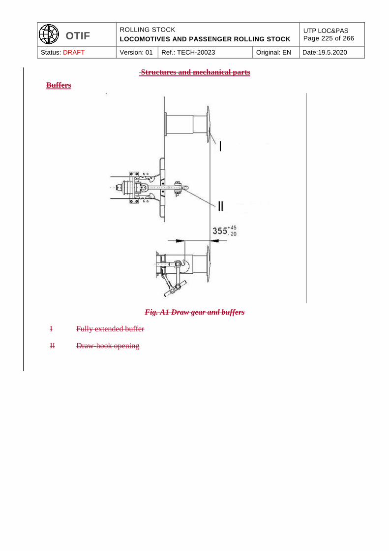
OTIF ROLLING STOCK
LOCOMOTIVES AND PASSENGER ROLLING STOCK
UTP LOC&PAS Page 225 of 266
Status: DRAFT Version: 01 Ref.: TECH-20023 Original: EN Date:19.5.2020
Structures and mechanical parts
Buffers
Fig. A1 Draw gear and buffers
I Fully extended buffer
II Draw-hook opening
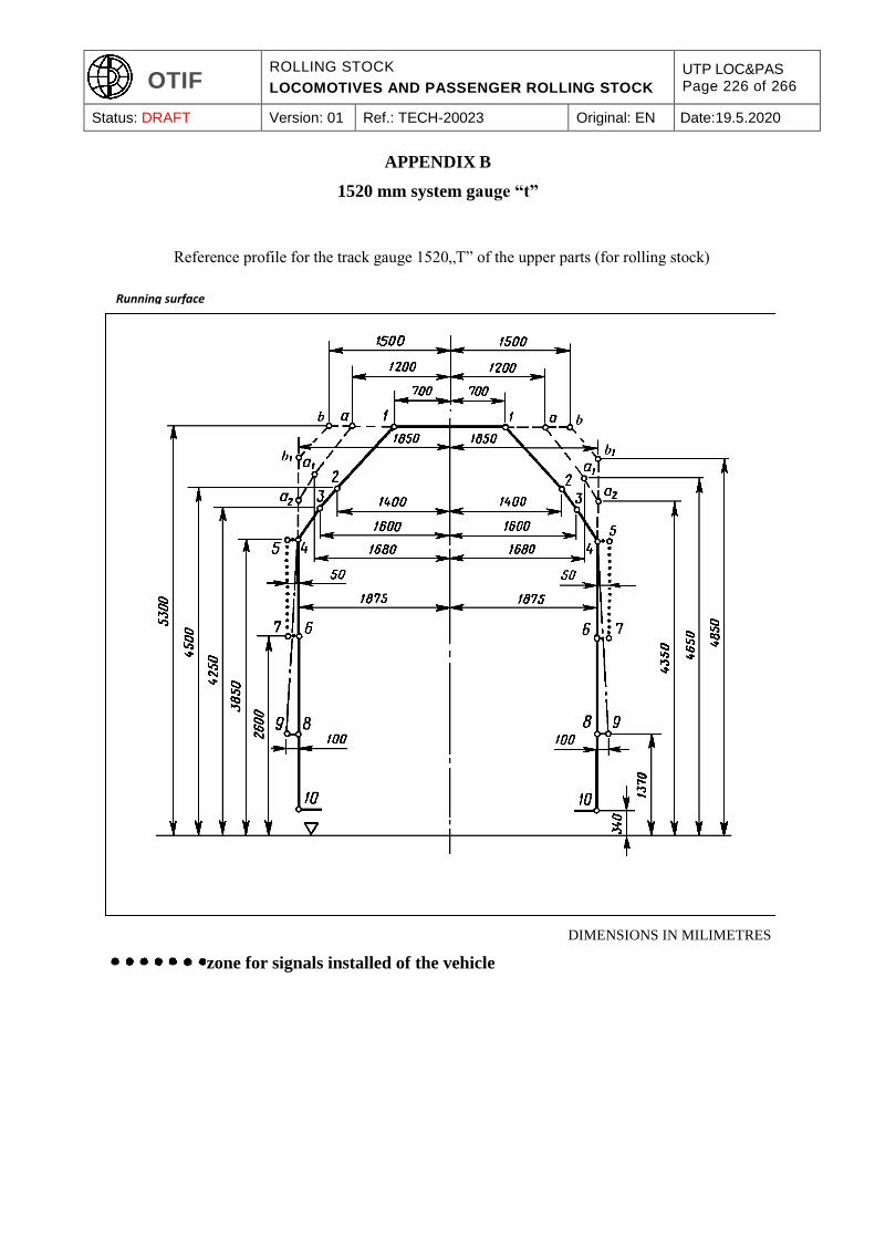
OTIF ROLLING STOCK
LOCOMOTIVES AND PASSENGER ROLLING STOCK
UTP LOC&PAS Page 226 of 266
Status: DRAFT Version: 01 Ref.: TECH-20023 Original: EN Date:19.5.2020
APPENDIX B
1520 mm system gauge “t”
Reference profile for the track gauge 1520„T” of the upper parts (for rolling stock)
DIMENSIONS IN MILIMETRES
zone for signals installed of the vehicle
Running surface
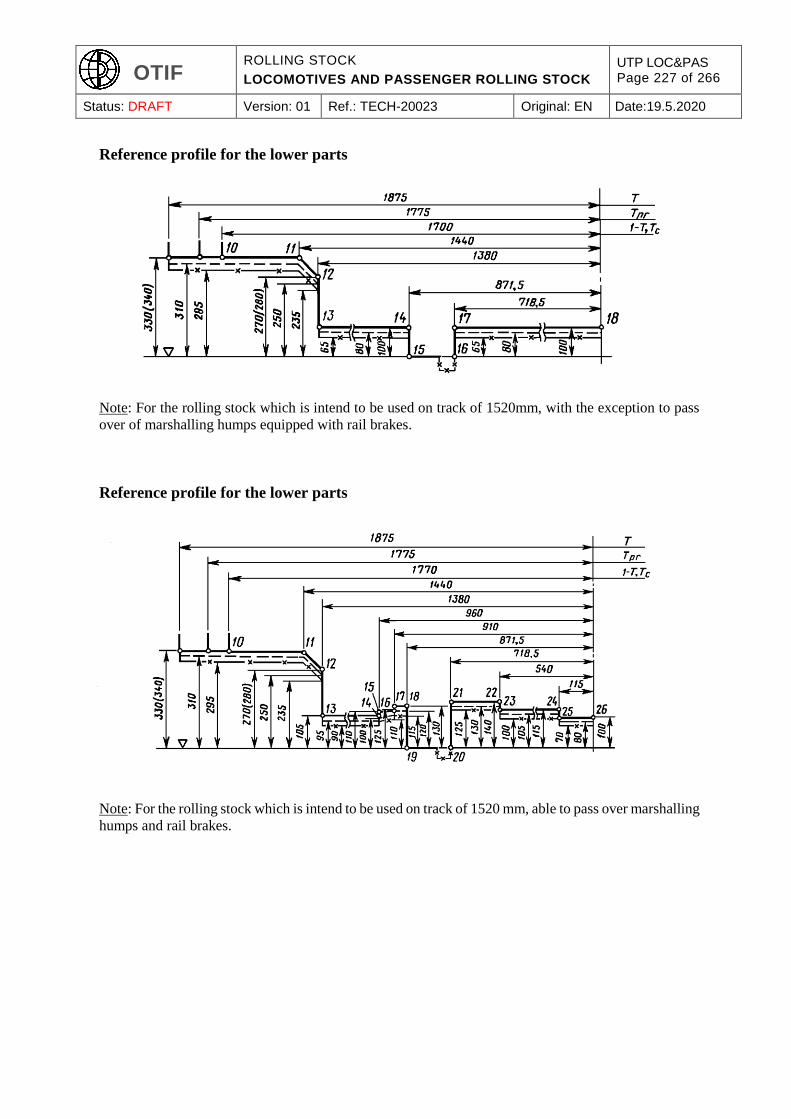
OTIF ROLLING STOCK
LOCOMOTIVES AND PASSENGER ROLLING STOCK
UTP LOC&PAS Page 227 of 266
Status: DRAFT Version: 01 Ref.: TECH-20023 Original: EN Date:19.5.2020
Reference profile for the lower parts
Note: For the rolling stock which is intend to be used on track of 1520mm, with the exception to pass
over of marshalling humps equipped with rail brakes.
Reference profile for the lower parts
Note: For the rolling stock which is intend to be used on track of 1520 mm, able to pass over marshalling
humps and rail brakes.
OTIF ROLLING STOCK
LOCOMOTIVES AND PASSENGER ROLLING STOCK
UTP LOC&PAS Page 228 of 266
Status: DRAFT Version: 01 Ref.: TECH-20023 Original: EN Date:19.5.2020
APPENDIX C
SPECIAL PROVISIONS FOR ON TRACK MACHINES (OTM)
C.1 Strength of vehicle structure
The requirements of the clause 4.2.2.4 of this
UTP TSI
are complemented as follow:
The machine frame shall be able to withstand either the static loads of the specification referenced in
Annex J-1, index 7 or the static loads according to the specification referenced in Annex J-1, index 102
without exceeding the permissible values given there in.
The corresponding structural category of the specification referenced in Annex J-1, index 102 is as
follows:
for machines not permitted to be loose shunted or hump shunted: F-II;
for all other machines: F-I.
The acceleration in x-direction according to the specification referenced in Annex J-1, index 7, Table
13 or to the specification referenced in Annex J-1, index 102, Table 10 shall be ±3 g.
C.2 Lifting and jacking
The machine body shall incorporate lifting points by which the whole machine is capable of being safely
lifted or jacked. The location of the lifting and jacking points shall be defined.
To facilitate the work during repair or inspection or when on-tracking the machines, the machines shall
be provided on both long sides with at least two lifting points, at which the machines can be lifted in
empty or loaded condition.
To allow positioning of jacking devices, clearances shall be provided under the lifting points which
shall not be blocked by the presence of non removable parts. The load cases shall be consistent with the
ones chosen in Appendix C.1 of this
UTP TSI
and shall apply for lifting and jacking under workshop and servicing operations.
C.3 Running dynamic behaviour
The running characteristics are permitted to be determined by running tests or by reference to a similar
type approved machine as detailed in clause 4.2.3.4.2 of this
UTP TSI
or by simulation.

OTIF ROLLING STOCK
LOCOMOTIVES AND PASSENGER ROLLING STOCK
UTP LOC&PAS Page 229 of 266
Status: DRAFT Version: 01 Ref.: TECH-20023 Original: EN Date:19.5.2020
The following additional deviations from the specification referenced in Annex J-1, index 16 apply:
The test shall always be taken as the simplified method for this type of machines
when running tests according to the specification referenced in Annex J-1, index 16 are done
with wheel profile in new condition, these are valid for a maximum distance of 50 000 km. After
50 000 km it is necessary to:
either re-profile the wheels;
or calculate the equivalent conicity of the worn profile and check that it does not differ more
than 50 % from the value of the test of the specification referenced in Annex J-1, index 16
(with a maximum difference of 0,05);
or make a new test according to the specification referenced in Annex J-1, index 16 with
worn wheel profile;
in general, stationary tests to determine the parameters of characteristic running gear in
accordance with to the specification referenced in Annex J-1, index 16, clause 5.3.14.3.2 are not
necessary;
if the required test speed cannot be obtained by the machine itself, the machine shall be hauled
for the tests.
when test zone 3 (as described in table 9 of to the specification referenced in Annex J-1, index
16) is used it is sufficient to have a minimum of 25 conformant track sections.
Running behaviour can be proven by simulation of the tests described in to the specification referenced
in Annex J-1, index 16 (with the exceptions as specified above) when there is a validated model of
representative track and operating conditions of the machine.
A model of a machine for simulation of running characteristics shall be validated by comparing the
model results against the results of running tests when the same input of track characteristic is used.
A validated model is a simulation model that has been verified by an actual running test that excites the
suspension sufficiently and where there is a close correlation between the results of the running test and
the predictions from the simulation model over the same test track.
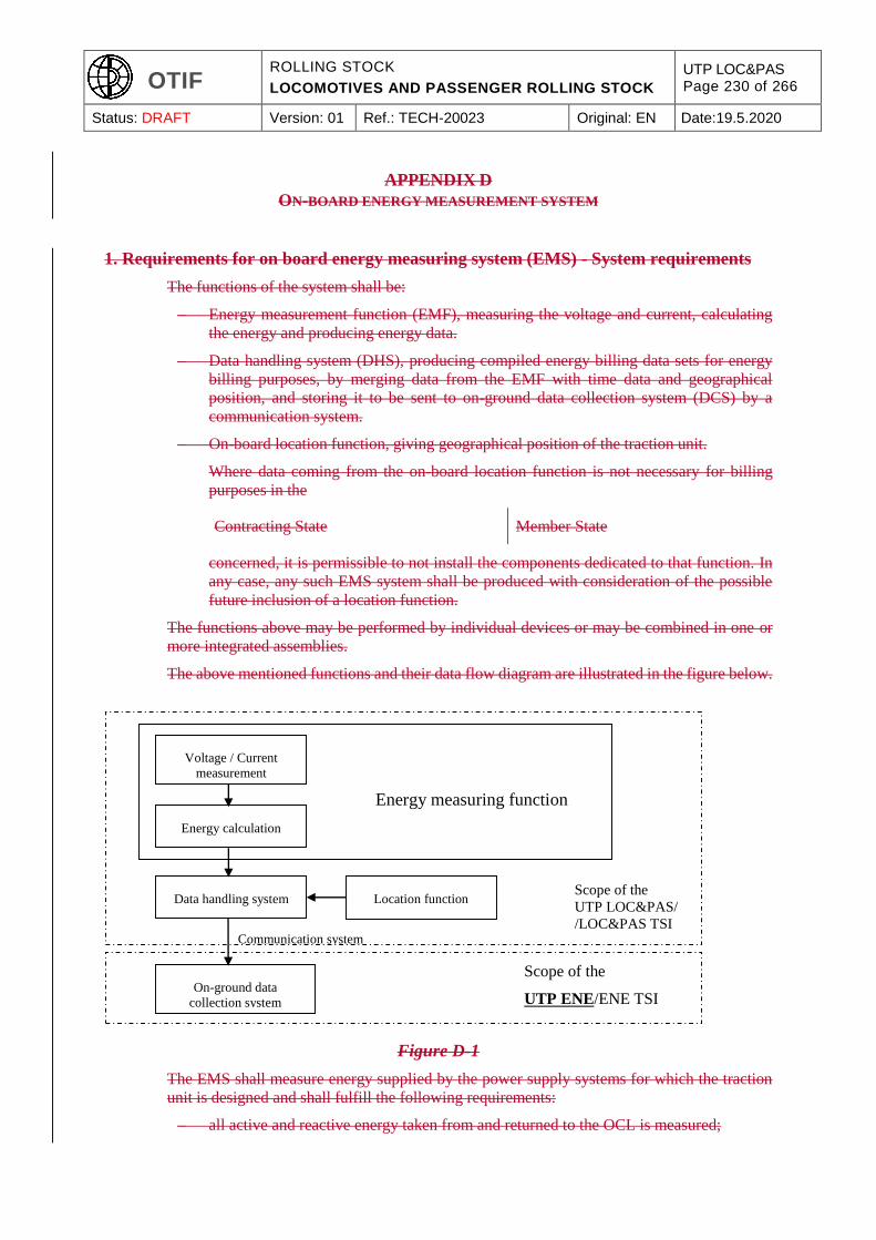
OTIF ROLLING STOCK
LOCOMOTIVES AND PASSENGER ROLLING STOCK
UTP LOC&PAS Page 230 of 266
Status: DRAFT Version: 01 Ref.: TECH-20023 Original: EN Date:19.5.2020
APPENDIX D
ON-BOARD ENERGY MEASUREMENT SYSTEM
1. Requirements for on board energy measuring system (EMS) - System requirements
The functions of the system shall be:
– Energy measurement function (EMF), measuring the voltage and current, calculating
the energy and producing energy data.
– Data handling system (DHS), producing compiled energy billing data sets for energy
billing purposes, by merging data from the EMF with time data and geographical
position, and storing it to be sent to on-ground data collection system (DCS) by a
communication system.
– On-board location function, giving geographical position of the traction unit.
Where data coming from the on-board location function is not necessary for billing
purposes in the
Contracting State Member State
concerned, it is permissible to not install the components dedicated to that function. In
any case, any such EMS system shall be produced with consideration of the possible
future inclusion of a location function.
The functions above may be performed by individual devices or may be combined in one or
more integrated assemblies.
The above mentioned functions and their data flow diagram are illustrated in the figure below.
Figure D-1
The EMS shall measure energy supplied by the power supply systems for which the traction
unit is designed and shall fulfill the following requirements:
– all active and reactive energy taken from and returned to the OCL is measured;
Voltage / Current
measurement
Energy calculation
Data handling system Location function
On-ground data
collection system
Energy measuring function
Scope of the
UTP LOC&PAS/
/LOC&PAS TSI
Communication system
Scope of the
UTP ENE/ENE TSI
OTIF ROLLING STOCK
LOCOMOTIVES AND PASSENGER ROLLING STOCK
UTP LOC&PAS Page 231 of 266
Status: DRAFT Version: 01 Ref.: TECH-20023 Original: EN Date:19.5.2020
– the EMS rated current and voltage shall be matched to the traction unit rated current and
voltage;
– it shall continue to function correctly when changing between traction energy supply
systems;
– the EMS shall be protected from non-authorised access;
– loss of the power supply to the EMS shall not affect data stored in the EMS.
It is permissible to access the data in the EMS for other purposes (e.g. feedback to the driver
in connection with the efficient operation of the train) provided that it can be demonstrated
that the integrity of EMS functions and data are not compromised by this arrangement.
2. Energy measuring function (EMF)
2.1. Metrological requirements
EMF is subject to metrological control, which shall be executed in accordance with the
following:
(1) Accuracy of EMF for active energy measurement shall comply with clauses 4.2.4.1 to 4.2.4.4
of the specification referenced in Annex J-1, index 103
(1) Each device containing one or more functions of EMF shall indicate:
(a) metrological control, and
(b) its accuracy class, according to the class designations specified in the specification
referenced in Annex J-1, index 103.
The accuracy class shall be verified by testing.
2.2. Other requirements
The measured energy values produced by EMF shall have a time reference period of 5 minutes
defined by the UTC clock time at the end of each time reference period; originating from the
time stamp 00:00:00.
It is permitted to use a shorter measuring period if the data can be aggregated on-board into 5
minutes time reference period.
3. Data handling system (DHS)
The DHS shall compile the data without corrupting them.
The DHS shall use, as a time reference, the same source of clock as in the EMF.
The DHS shall incorporate data storage with a memory capacity sufficient to store the
compiled data of at least 60 days continuous work.
The DHS shall have a capability to be interrogated locally by authorised personnel on board
the train using appropriate equipment (e.g. laptop computer) in order to provide an opportunity
for audit, and an alternative method of recovering data.
The DHS shall produce CEBD (compiled energy billing data sets) by merging the following
data for each time reference period:
OTIF ROLLING STOCK
LOCOMOTIVES AND PASSENGER ROLLING STOCK
UTP LOC&PAS Page 232 of 266
Status: DRAFT Version: 01 Ref.: TECH-20023 Original: EN Date:19.5.2020
unique EMS identification number, consisting of the European vehicle number
(EVN) followed by one additional digit uniquely identifying each EMS on-board the
traction unit, and no dividers included;
end time of each period, defined as year, month, day, hour, minute and second;
the location data at the end of each period;
consumed/regenerated active and reactive (if appropriate) energy in each period, in
units of Watt-hour (active energy) and var-hour (reactive energy) or their decimal-
multiples.
4. Location function
The location function shall provide location data to the DHS which originates from an external
source.
The data from the location function shall be synchronised in accordance with UTC clock time
and time reference period with the on-board EMF.
The location function shall provide the position expressed in latitude and longitude using
decimal degrees with five decimal places. Positive values shall be used for North and East;
negative values shall be used for South and West.
In open air the location function shall have an accuracy of 250 m or less.
5. On-board to ground communication
The specification related to interface protocols and transferred data format are an open point.
6. Particular assessment procedures
6.1. Energy measurement system
Where assessment methods set out in the standard series referenced in Annex J-1, index 103,
104 and 105 are referenced below, only those aspects necessary for the assessment of the
requirements above in this Appendix D shall be undertaken in relation to the EMS which is a
part of the
UTP verification EC verification
activity for the rolling stock subsystem.
6.1.1. EMF
The accuracy of the each device containing one or more functions of EMF shall be assessed
by testing each function, under reference conditions, using the relevant method as described
in clause 5.4.3.4.1, 5.4.3.4.2 and 5.4.4.3.1 of the specification referenced in Annex J-1, index
103. The input quantity and power factor range when testing shall correspond to the values set
out in Table 3 of the specification referenced in Annex J-1, index 103.
The accuracy of the complete EMF shall be assessed by calculation, using the method
described in clause 4.2.4.2 of the specification referenced in Annex J-1, index 103.
OTIF ROLLING STOCK
LOCOMOTIVES AND PASSENGER ROLLING STOCK
UTP LOC&PAS Page 233 of 266
Status: DRAFT Version: 01 Ref.: TECH-20023 Original: EN Date:19.5.2020
The effects of temperature on accuracy of the each device containing one or more functions of
EMF shall be assessed by testing each function, under reference conditions (except for
temperature), using the relevant method as described in clause 5.4.3.4.3.1, and 5.4.4.3.2.1 of
the specification referenced in Annex J-1, index 103.
The mean temperature coefficient of each device containing one or more functions of EMF
shall be assessed by testing each function, under reference conditions (except for temperature),
using the relevant method as described in clause 5.4.3.4.3.2 and 5.4.4.3.2.2 of the specification
referenced in Annex J-1, index 103.
6.1.2 DHS
The compiling and handling of data within the DHS shall be assessed by testing using the
method as described in clause 5.4.8.3.1, 5.4.8.5.1, 5.4.8.5.2 and 5.4.8.6 of the specification
referenced in Annex J-1, index 104.
6.1.3 EMS
The correct functioning of the EMS shall be assessed by testing using the method as described
in clause 5.3.2.2, 5.3.2.3, 5.3.2.4 and 5.5.3.2 of the specification referenced in Annex J-1,
index 105.
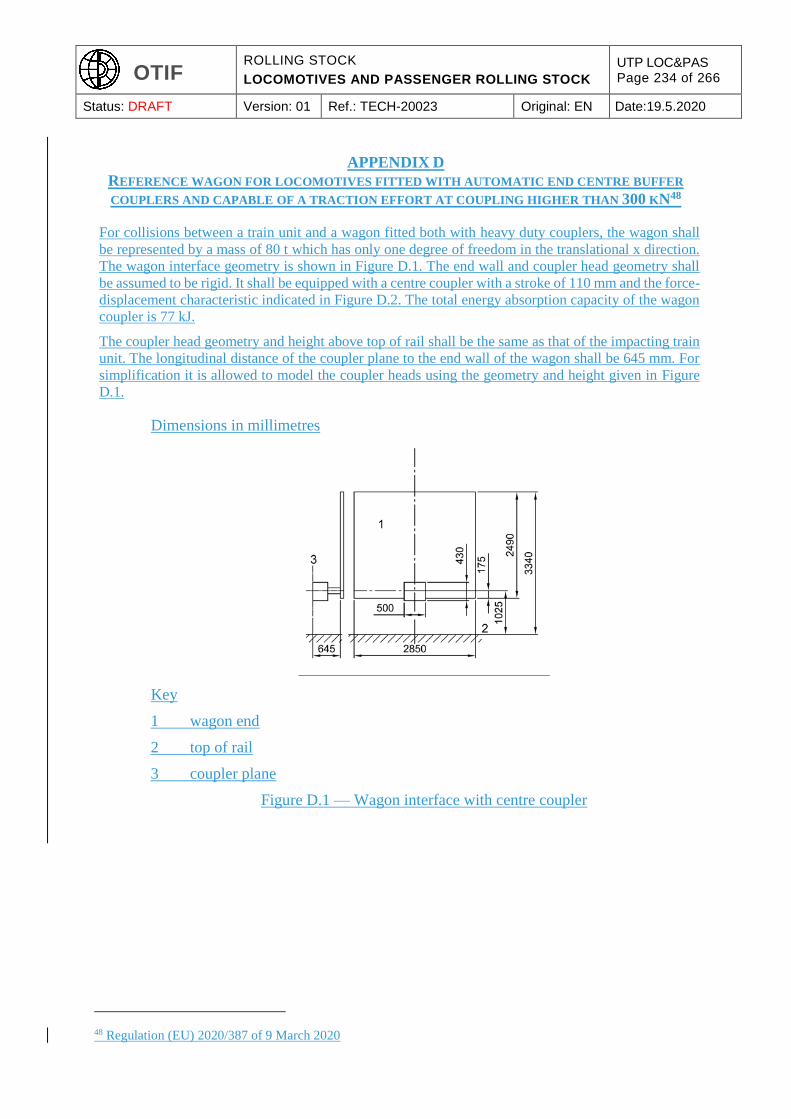
OTIF ROLLING STOCK
LOCOMOTIVES AND PASSENGER ROLLING STOCK
UTP LOC&PAS Page 234 of 266
Status: DRAFT Version: 01 Ref.: TECH-20023 Original: EN Date:19.5.2020
APPENDIX D
REFERENCE WAGON FOR LOCOMOTIVES FITTED WITH AUTOMATIC END CENTRE BUFFER
COUPLERS AND CAPABLE OF A TRACTION EFFORT AT COUPLING HIGHER THAN 300 KN48
For collisions between a train unit and a wagon fitted both with heavy duty couplers, the wagon shall
be represented by a mass of 80 t which has only one degree of freedom in the translational x direction.
The wagon interface geometry is shown in Figure D.1. The end wall and coupler head geometry shall
be assumed to be rigid. It shall be equipped with a centre coupler with a stroke of 110 mm and the force-
displacement characteristic indicated in Figure D.2. The total energy absorption capacity of the wagon
coupler is 77 kJ.
The coupler head geometry and height above top of rail shall be the same as that of the impacting train
unit. The longitudinal distance of the coupler plane to the end wall of the wagon shall be 645 mm. For
simplification it is allowed to model the coupler heads using the geometry and height given in Figure
D.1.
Dimensions in millimetres
Key
1 wagon end
2 top of rail
3 coupler plane
Figure D.1 — Wagon interface with centre coupler
48 Regulation (EU) 2020/387 of 9 March 2020
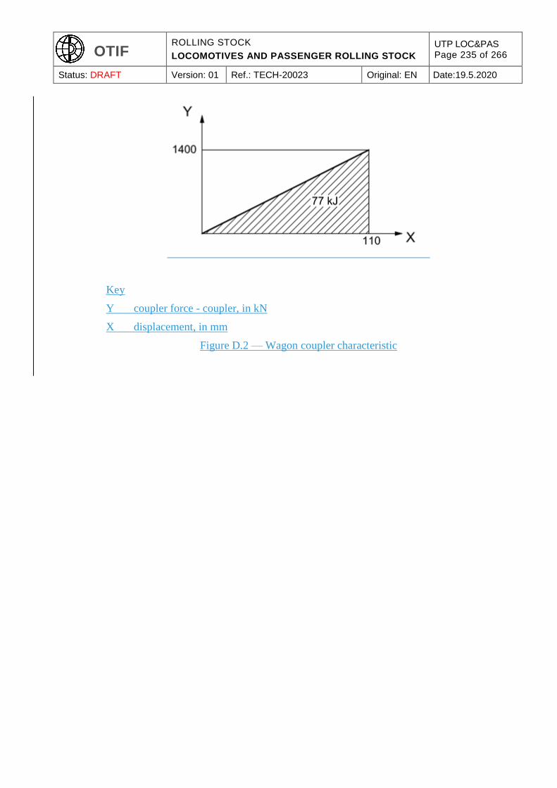
OTIF ROLLING STOCK
LOCOMOTIVES AND PASSENGER ROLLING STOCK
UTP LOC&PAS Page 235 of 266
Status: DRAFT Version: 01 Ref.: TECH-20023 Original: EN Date:19.5.2020
Key
Y coupler force - coupler, in kN
X displacement, in mm
Figure D.2 — Wagon coupler characteristic
OTIF ROLLING STOCK
LOCOMOTIVES AND PASSENGER ROLLING STOCK
UTP LOC&PAS Page 236 of 266
Status: DRAFT Version: 01 Ref.: TECH-20023 Original: EN Date:19.5.2020
APPENDIX E
ANTHROPOMETRIC MEASUREMENTS OF THE DRIVER
The following data represents the “state of the art” and shall be used.
Note: they will be subject of an EN standard currently under drafting process.
Principal anthropometric measurements of the shortest and tallest driving staff:
The dimensions given in Appendix E of the UIC 651 (4th edition, July 2002) shall be taken into
consideration.
Additional anthropometric dimensions of the shortest and tallest driving staff:
The dimensions given in Appendix G of the UIC 651 (4th edition, July 2002) shall be taken into
consideration.
OTIF ROLLING STOCK
LOCOMOTIVES AND PASSENGER ROLLING STOCK
UTP LOC&PAS Page 237 of 266
Status: DRAFT Version: 01 Ref.: TECH-20023 Original: EN Date:19.5.2020
APPENDIX F
FRONT VISIBILITY
The following data represents the “state of the art” and shall be used.
Note: they will be subject of an EN standard currently under drafting process.
F.1. General
The design of the cab shall support the drivers’ view of all external information that form part of the
driving task as well as protecting the driver from external sources of visual interference. This shall
include the following:
Flicker at the lower edge of the windscreen, which can cause fatigue, shall be reduced
Protection shall be provided from the sun and glare of headlights from oncoming trains, without
reducing the drivers’ view of external signs, signals and other visual information
Location of cab equipment shall not block or distort the drivers view of external information
The dimension, location, shape and finishes (including maintenance) of the windows shall not
inhibit the drivers external view and shall support the driving task
The location, type and quality of windscreen cleaning and clearance devices shall ensure that
the driver is able to maintain a clear external view in most weather and operating conditions,
and shall not inhibit the drivers external view.
The driver’s cab shall be designed in such a way that the driver is facing forwards when driving.
The driver’s cab shall be designed to allow the driver at his seated driving position a clear and
unobstructed line of sight in order to distinguish fixed signals set to both the left and right of the
track, as defined in Appendix D of the UIC 651(4th edition, July 2002).
Note: the position of the seat in the Appendix D mentioned here above has to be considered as an
example; the
UTP TSI
does not impose the position of the seat (left, central or right) in the cab; the
UTP TSI
does not impose the standing driving position on all types of units.
The rules expressed in the Appendix above govern the conditions of visibility for each running direction
along straight track and in curves with a radius of 300 m and more. They apply to the position(s) of the
driver.
Notes:
in case of cab fitted with 2 driver’s seats (option with 2 driving positions), they apply to the 2
seated positions.
for locomotives with central cab and for OTMs, the clause 4.2.9.1.3.1 of the

OTIF ROLLING STOCK
LOCOMOTIVES AND PASSENGER ROLLING STOCK
UTP LOC&PAS Page 238 of 266
Status: DRAFT Version: 01 Ref.: TECH-20023 Original: EN Date:19.5.2020
UTP TSI
specify particular conditions.
F.2. Reference position of vehicle in relation to track:
The clause 3.2.1 of the UIC 651 (4th edition, July 2002) shall apply.
The supplies and payload shall be considered as defined in the specification referenced in Annex J-1,
index 13 and clause 4.2.2.10 of this
UTP. TSI.
F.3. Reference position for the eyes of crew members
The clause 3.2.2 of the UIC 651 (4th edition, July 2002) shall apply.
The distance from the driver’s eyes in seating posture to the windscreen shall be higher than or equal to
500 mm.
F.4. Conditions of visibility
The clause 3.3 of the UIC 651 (4th edition, July 2002) shall apply.
Note: the clause 3.3.1 of the UIC 651 refers for the standing position to its clause 2.7.2, specifying a
minimum distance of 1.8 meters between floor and top edge of the front window.

OTIF ROLLING STOCK
LOCOMOTIVES AND PASSENGER ROLLING STOCK
UTP LOC&PAS Page 239 of 266
Status: DRAFT Version: 01 Ref.: TECH-20023 Original: EN Date:19.5.2020
APPENDIX G
SERVICING
Connections for the toilet discharge system on rolling stock
General tolerances +/- 0,1
Material: stainless steel
Fig. G1 Evacuation nozzle (Inner part)
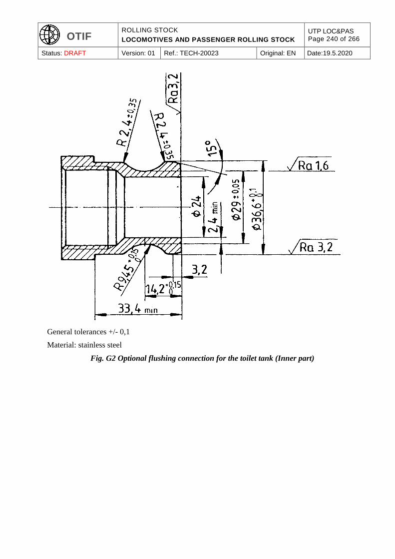
OTIF ROLLING STOCK
LOCOMOTIVES AND PASSENGER ROLLING STOCK
UTP LOC&PAS Page 240 of 266
Status: DRAFT Version: 01 Ref.: TECH-20023 Original: EN Date:19.5.2020
General tolerances +/- 0,1
Material: stainless steel
Fig. G2 Optional flushing connection for the toilet tank (Inner part)
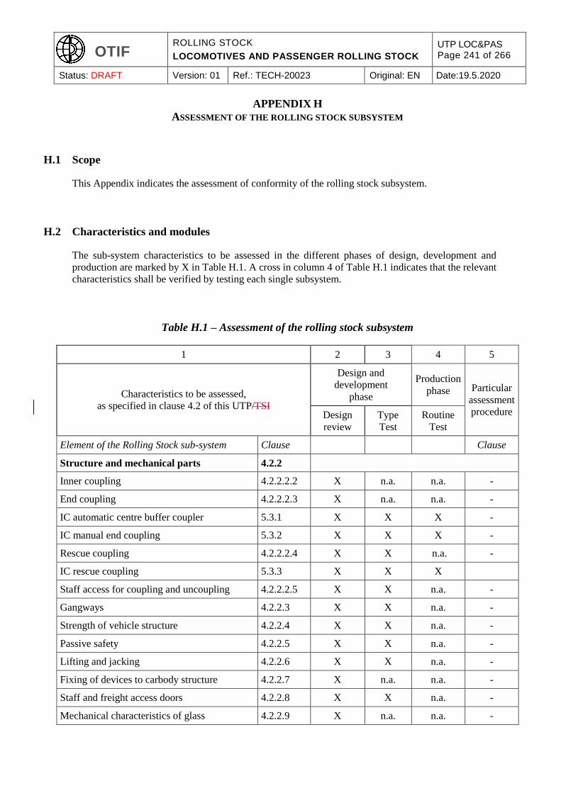
OTIF ROLLING STOCK
LOCOMOTIVES AND PASSENGER ROLLING STOCK
UTP LOC&PAS Page 241 of 266
Status: DRAFT Version: 01 Ref.: TECH-20023 Original: EN Date:19.5.2020
APPENDIX H
ASSESSMENT OF THE ROLLING STOCK SUBSYSTEM
H.1 Scope
This Appendix indicates the assessment of conformity of the rolling stock subsystem.
H.2 Characteristics and modules
The sub-system characteristics to be assessed in the different phases of design, development and
production are marked by X in Table H.1. A cross in column 4 of Table H.1 indicates that the relevant
characteristics shall be verified by testing each single subsystem.
Table H.1 – Assessment of the rolling stock subsystem
1 2 3 4 5
Characteristics to be assessed,
as specified in clause 4.2 of this UTP/TSI
Design and
development
phase
Production
phase Particular
assessment
procedure Design
review
Type
Test
Routine
Test
Element of the Rolling Stock sub-system Clause Clause
Structure and mechanical parts 4.2.2
Inner coupling 4.2.2.2.2 X n.a. n.a. -
End coupling 4.2.2.2.3 X n.a. n.a. -
IC automatic centre buffer coupler 5.3.1 X X X -
IC manual end coupling 5.3.2 X X X -
Rescue coupling 4.2.2.2.4 X X n.a. -
IC rescue coupling 5.3.3 X X X
Staff access for coupling and uncoupling 4.2.2.2.5 X X n.a. -
Gangways 4.2.2.3 X X n.a. -
Strength of vehicle structure 4.2.2.4 X X n.a. -
Passive safety 4.2.2.5 X X n.a. -
Lifting and jacking 4.2.2.6 X X n.a. -
Fixing of devices to carbody structure 4.2.2.7 X n.a. n.a. -
Staff and freight access doors 4.2.2.8 X X n.a. -
Mechanical characteristics of glass 4.2.2.9 X n.a. n.a. -
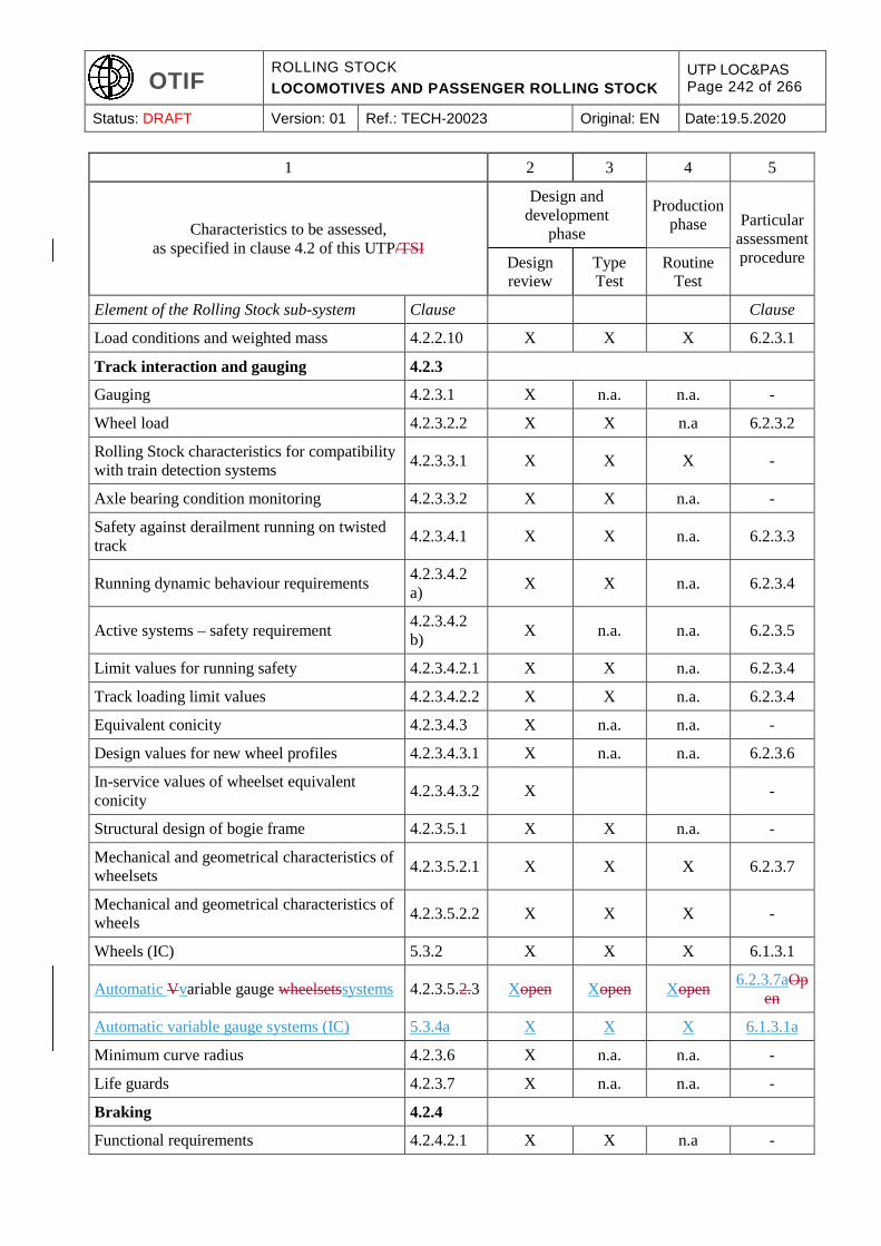
OTIF ROLLING STOCK
LOCOMOTIVES AND PASSENGER ROLLING STOCK
UTP LOC&PAS Page 242 of 266
Status: DRAFT Version: 01 Ref.: TECH-20023 Original: EN Date:19.5.2020
1 2 3 4 5
Characteristics to be assessed,
as specified in clause 4.2 of this UTP/TSI
Design and
development
phase
Production
phase Particular
assessment
procedure Design
review
Type
Test
Routine
Test
Element of the Rolling Stock sub-system Clause Clause
Load conditions and weighted mass 4.2.2.10 X X X 6.2.3.1
Track interaction and gauging 4.2.3
Gauging 4.2.3.1 X n.a. n.a. -
Wheel load 4.2.3.2.2 X X n.a 6.2.3.2
Rolling Stock characteristics for compatibility
with train detection systems 4.2.3.3.1 X X X -
Axle bearing condition monitoring 4.2.3.3.2 X X n.a. -
Safety against derailment running on twisted
track 4.2.3.4.1 X X n.a. 6.2.3.3
Running dynamic behaviour requirements 4.2.3.4.2
a) X X n.a. 6.2.3.4
Active systems – safety requirement 4.2.3.4.2
b) X n.a. n.a. 6.2.3.5
Limit values for running safety 4.2.3.4.2.1 X X n.a. 6.2.3.4
Track loading limit values 4.2.3.4.2.2 X X n.a. 6.2.3.4
Equivalent conicity 4.2.3.4.3 X n.a. n.a. -
Design values for new wheel profiles 4.2.3.4.3.1 X n.a. n.a. 6.2.3.6
In-service values of wheelset equivalent
conicity 4.2.3.4.3.2 X -
Structural design of bogie frame 4.2.3.5.1 X X n.a. -
Mechanical and geometrical characteristics of
wheelsets 4.2.3.5.2.1 X X X 6.2.3.7
Mechanical and geometrical characteristics of
wheels 4.2.3.5.2.2 X X X -
Wheels (IC) 5.3.2 X X X 6.1.3.1
Automatic Vvariable gauge wheelsetssystems 4.2.3.5.2.3 Xopen Xopen Xopen 6.2.3.7aOp
en
Automatic variable gauge systems (IC) 5.3.4a X X X 6.1.3.1a
Minimum curve radius 4.2.3.6 X n.a. n.a. -
Life guards 4.2.3.7 X n.a. n.a. -
Braking 4.2.4
Functional requirements 4.2.4.2.1 X X n.a -
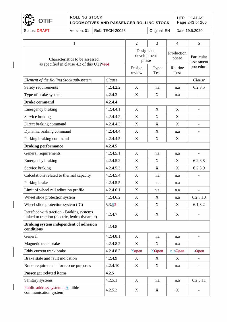
OTIF ROLLING STOCK
LOCOMOTIVES AND PASSENGER ROLLING STOCK
UTP LOC&PAS Page 243 of 266
Status: DRAFT Version: 01 Ref.: TECH-20023 Original: EN Date:19.5.2020
1 2 3 4 5
Characteristics to be assessed,
as specified in clause 4.2 of this UTP/TSI
Design and
development
phase
Production
phase Particular
assessment
procedure Design
review
Type
Test
Routine
Test
Element of the Rolling Stock sub-system Clause Clause
Safety requirements 4.2.4.2.2 X n.a n.a 6.2.3.5
Type of brake system 4.2.4.3 X X n.a -
Brake command 4.2.4.4
Emergency braking 4.2.4.4.1 X X X -
Service braking 4.2.4.4.2 X X X -
Direct braking command 4.2.4.4.3 X X X -
Dynamic braking command 4.2.4.4.4 X X n.a -
Parking braking command 4.2.4.4.5 X X X -
Braking performance 4.2.4.5
General requirements 4.2.4.5.1 X n.a n.a -
Emergency braking 4.2.4.5.2 X X X 6.2.3.8
Service braking 4.2.4.5.3 X X X 6.2.3.9
Calculations related to thermal capacity 4.2.4.5.4 X n.a n.a -
Parking brake 4.2.4.5.5 X n.a n.a -
Limit of wheel rail adhesion profile 4.2.4.6.1 X n.a n.a -
Wheel slide protection system 4.2.4.6.2 X X n.a 6.2.3.10
Wheel slide protection system (IC) 5.3.53 X X X 6.1.3.2
Interface with traction - Braking systems
linked to traction (electric, hydro-dynamic) 4.2.4.7 X X X -
Braking system independent of adhesion
conditions 4.2.4.8
General 4.2.4.8.1 X n.a n.a -
Magnetic track brake 4.2.4.8.2 X X n.a -
Eddy current track brake 4.2.4.8.3 Xopen XOpen n.aOpen -Open
Brake state and fault indication 4.2.4.9 X X X -
Brake requirements for rescue purposes 4.2.4.10 X X n.a -
Passenger related items 4.2.5
Sanitary systems 4.2.5.1 X n.a n.a 6.2.3.11
Public address system: aAudible
communication system 4.2.5.2 X X X -
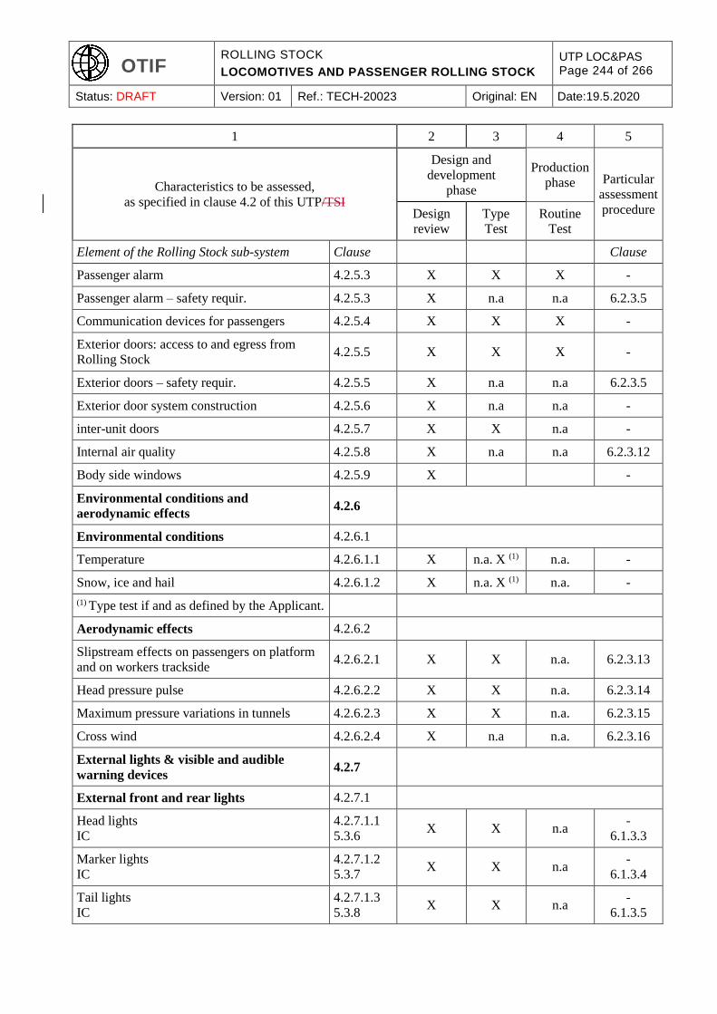
OTIF ROLLING STOCK
LOCOMOTIVES AND PASSENGER ROLLING STOCK
UTP LOC&PAS Page 244 of 266
Status: DRAFT Version: 01 Ref.: TECH-20023 Original: EN Date:19.5.2020
1 2 3 4 5
Characteristics to be assessed,
as specified in clause 4.2 of this UTP/TSI
Design and
development
phase
Production
phase Particular
assessment
procedure Design
review
Type
Test
Routine
Test
Element of the Rolling Stock sub-system Clause Clause
Passenger alarm 4.2.5.3 X X X -
Passenger alarm – safety requir. 4.2.5.3 X n.a n.a 6.2.3.5
Communication devices for passengers 4.2.5.4 X X X -
Exterior doors: access to and egress from
Rolling Stock 4.2.5.5 X X X -
Exterior doors – safety requir. 4.2.5.5 X n.a n.a 6.2.3.5
Exterior door system construction 4.2.5.6 X n.a n.a -
inter-unit doors 4.2.5.7 X X n.a -
Internal air quality 4.2.5.8 X n.a n.a 6.2.3.12
Body side windows 4.2.5.9 X -
Environmental conditions and
aerodynamic effects 4.2.6
Environmental conditions 4.2.6.1
Temperature 4.2.6.1.1 X n.a. X (1) n.a. -
Snow, ice and hail 4.2.6.1.2 X n.a. X (1) n.a. -
(1) Type test if and as defined by the Applicant.
Aerodynamic effects 4.2.6.2
Slipstream effects on passengers on platform
and on workers trackside 4.2.6.2.1 X X n.a. 6.2.3.13
Head pressure pulse 4.2.6.2.2 X X n.a. 6.2.3.14
Maximum pressure variations in tunnels 4.2.6.2.3 X X n.a. 6.2.3.15
Cross wind 4.2.6.2.4 X n.a n.a. 6.2.3.16
External lights & visible and audible
warning devices 4.2.7
External front and rear lights 4.2.7.1
Head lights
IC
4.2.7.1.1
5.3.6 X X n.a
-
6.1.3.3
Marker lights
IC
4.2.7.1.2
5.3.7 X X n.a
-
6.1.3.4
Tail lights
IC
4.2.7.1.3
5.3.8 X X n.a
-
6.1.3.5
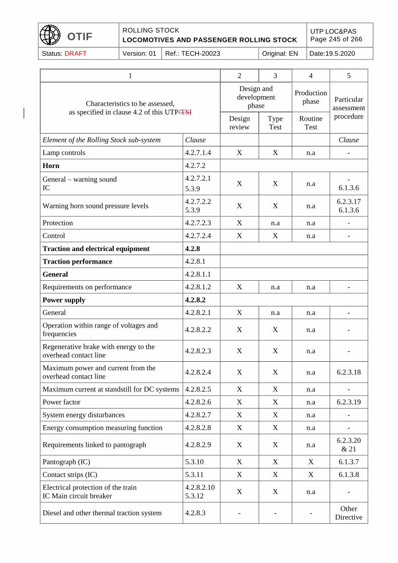
OTIF ROLLING STOCK
LOCOMOTIVES AND PASSENGER ROLLING STOCK
UTP LOC&PAS Page 245 of 266
Status: DRAFT Version: 01 Ref.: TECH-20023 Original: EN Date:19.5.2020
1 2 3 4 5
Characteristics to be assessed,
as specified in clause 4.2 of this UTP/TSI
Design and
development
phase
Production
phase Particular
assessment
procedure Design
review
Type
Test
Routine
Test
Element of the Rolling Stock sub-system Clause Clause
Lamp controls 4.2.7.1.4 X X n.a -
Horn 4.2.7.2
General – warning sound
IC
4.2.7.2.1
5.3.9 X X n.a
-
6.1.3.6
Warning horn sound pressure levels 4.2.7.2.2
5.3.9 X X n.a
6.2.3.17
6.1.3.6
Protection 4.2.7.2.3 X n.a n.a -
Control 4.2.7.2.4 X X n.a -
Traction and electrical equipment 4.2.8
Traction performance 4.2.8.1
General 4.2.8.1.1
Requirements on performance 4.2.8.1.2 X n.a n.a -
Power supply 4.2.8.2
General 4.2.8.2.1 X n.a n.a -
Operation within range of voltages and
frequencies 4.2.8.2.2 X X n.a -
Regenerative brake with energy to the
overhead contact line 4.2.8.2.3 X X n.a -
Maximum power and current from the
overhead contact line 4.2.8.2.4 X X n.a 6.2.3.18
Maximum current at standstill for DC systems 4.2.8.2.5 X X n.a -
Power factor 4.2.8.2.6 X X n.a 6.2.3.19
System energy disturbances 4.2.8.2.7 X X n.a -
Energy consumption measuring function 4.2.8.2.8 X X n.a -
Requirements linked to pantograph 4.2.8.2.9 X X n.a 6.2.3.20
& 21
Pantograph (IC) 5.3.10 X X X 6.1.3.7
Contact strips (IC) 5.3.11 X X X 6.1.3.8
Electrical protection of the train
IC Main circuit breaker
4.2.8.2.10
5.3.12 X X n.a -
Diesel and other thermal traction system 4.2.8.3 - - - Other
Directive
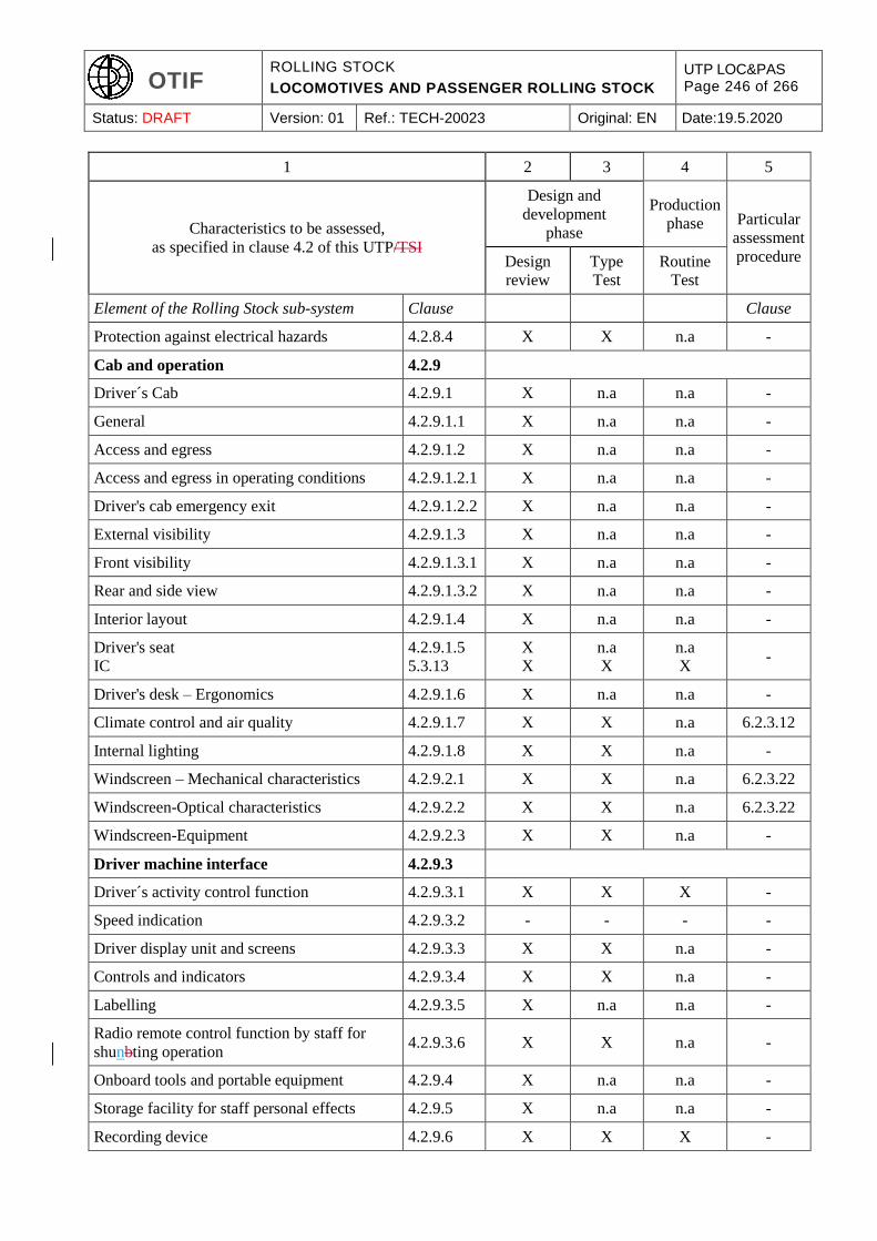
OTIF ROLLING STOCK
LOCOMOTIVES AND PASSENGER ROLLING STOCK
UTP LOC&PAS Page 246 of 266
Status: DRAFT Version: 01 Ref.: TECH-20023 Original: EN Date:19.5.2020
1 2 3 4 5
Characteristics to be assessed,
as specified in clause 4.2 of this UTP/TSI
Design and
development
phase
Production
phase Particular
assessment
procedure Design
review
Type
Test
Routine
Test
Element of the Rolling Stock sub-system Clause Clause
Protection against electrical hazards 4.2.8.4 X X n.a -
Cab and operation 4.2.9
Driver´s Cab 4.2.9.1 X n.a n.a -
General 4.2.9.1.1 X n.a n.a -
Access and egress 4.2.9.1.2 X n.a n.a -
Access and egress in operating conditions 4.2.9.1.2.1 X n.a n.a -
Driver's cab emergency exit 4.2.9.1.2.2 X n.a n.a -
External visibility 4.2.9.1.3 X n.a n.a -
Front visibility 4.2.9.1.3.1 X n.a n.a -
Rear and side view 4.2.9.1.3.2 X n.a n.a -
Interior layout 4.2.9.1.4 X n.a n.a -
Driver's seat
IC
4.2.9.1.5
5.3.13
X
X
n.a
X
n.a
X -
Driver's desk – Ergonomics 4.2.9.1.6 X n.a n.a -
Climate control and air quality 4.2.9.1.7 X X n.a 6.2.3.12
Internal lighting 4.2.9.1.8 X X n.a -
Windscreen – Mechanical characteristics 4.2.9.2.1 X X n.a 6.2.3.22
Windscreen-Optical characteristics 4.2.9.2.2 X X n.a 6.2.3.22
Windscreen-Equipment 4.2.9.2.3 X X n.a -
Driver machine interface 4.2.9.3
Driver´s activity control function 4.2.9.3.1 X X X -
Speed indication 4.2.9.3.2 - - - -
Driver display unit and screens 4.2.9.3.3 X X n.a -
Controls and indicators 4.2.9.3.4 X X n.a -
Labelling 4.2.9.3.5 X n.a n.a -
Radio remote control function by staff for
shunbting operation 4.2.9.3.6 X X n.a -
Onboard tools and portable equipment 4.2.9.4 X n.a n.a -
Storage facility for staff personal effects 4.2.9.5 X n.a n.a -
Recording device 4.2.9.6 X X X -
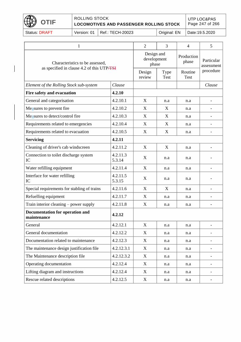
OTIF ROLLING STOCK
LOCOMOTIVES AND PASSENGER ROLLING STOCK
UTP LOC&PAS Page 247 of 266
Status: DRAFT Version: 01 Ref.: TECH-20023 Original: EN Date:19.5.2020
1 2 3 4 5
Characteristics to be assessed,
as specified in clause 4.2 of this UTP/TSI
Design and
development
phase
Production
phase Particular
assessment
procedure Design
review
Type
Test
Routine
Test
Element of the Rolling Stock sub-system Clause Clause
Fire safety and evacuation 4.2.10
General and categorisation 4.2.10.1 X n.a n.a -
Measures to prevent fire 4.2.10.2 X X n.a -
Measures to detect/control fire 4.2.10.3 X X n.a -
Requirements related to emergencies 4.2.10.4 X X n.a -
Requirements related to evacuation 4.2.10.5 X X n.a -
Servicing 4.2.11
Cleaning of driver's cab windscreen 4.2.11.2 X X n.a -
Connection to toilet discharge system
IC
4.2.11.3
5.3.14 X n.a n.a -
Water refilling equipment 4.2.11.4 X n.a n.a -
Interface for water refilling
IC
4.2.11.5
5.3.15 X n.a n.a -
Special requirements for stabling of trains 4.2.11.6 X X n.a -
Refuelling equipment 4.2.11.7 X n.a n.a -
Train interior cleaning – power supply 4.2.11.8 X n.a n.a -
Documentation for operation and
maintenance 4.2.12
General 4.2.12.1 X n.a n.a -
General documentation 4.2.12.2 X n.a n.a -
Documentation related to maintenance 4.2.12.3 X n.a n.a -
The maintenance design justification file 4.2.12.3.1 X n.a n.a -
The Maintenance description file 4.2.12.3.2 X n.a n.a -
Operating documentation 4.2.12.4 X n.a n.a -
Lifting diagram and instructions 4.2.12.4 X n.a n.a -
Rescue related descriptions 4.2.12.5 X n.a n.a -

OTIF ROLLING STOCK
LOCOMOTIVES AND PASSENGER ROLLING STOCK
UTP LOC&PAS Page 248 of 266
Status: DRAFT Version: 01 Ref.: TECH-20023 Original: EN Date:19.5.2020
APPENDIX I
ASPECTS FOR WHICH THE TECHNICAL SPECIFICATION IS NOT AVAILABLE (OPEN POINTS)
Open points that relate to technical compatibility between the vehicle and the network:
Element of the Rolling
Stock sub-system
Clause of this
UTP/TSI
Technical aspect not
covered by this UTP/TSI
Comments
Compatibility with train
detection systems
4.2.3.3.1 See specification referenced
in Annex J-2, index 1.
Open points also identified in
the TSI CCS.
Running dynamic behaviour
for 1520 mm track gauge
system
4.2.3.4.2
4.2.3.4.3
Running dynamic
behaviour. Equivalent
conicity.
Normative documents
referred to in the UTP/TSI are
based on experience gained
on the 1435 mm system.
Braking system independent
of adhesion conditions
4.2.4.8.3 Eddy current track brake Equipment not mandatory.
Electromagnetic
Ccompatibility with
concerned network to be
checked.
Aerodynamic effects for
1520 mm,1524 mm and
1668 mm track gauge
systems
4.2.6.2 Limit values and conformity
assessment
Normative documents
referred to in the UTP/TSI are
based on experience gained
on the 1435 mm system.
Aerodynamic effect on
ballasted track for RST of
design speed ˃≥
250190 km/h
4.2.6.2.5 Limit value and conformity
assessment in order to limit
risks induced by the
projection of ballast
On-going work within CEN.
Open point also in TSI INF.
Open points that do not relate to technical compatibility between the vehicle and the network:
Element of the Rolling
Stock sub-system
Clause of this
UTP/TSI
Technical aspect not
covered by this UTP/TSI
Comments
Passive Safety 4.2.2.5 Application of scenarios 1
and 2 to locomotives with
centre couplers and traction
effort higher than 300 kN.
If no technical solution
available, possible restrictions
at the level of operation.
Variable gauge wheelsets 4.2.3.5.2.3 Conformity assessment Design option.
On-board energy
measurement system
4.2.8.2.8 &
Appendix D On-board to ground
communication:
specification related to
interface protocols and
transferred data format.
Description of on-board to
ground communication shall
be provided in the technical
documentation.
The standard series EN
61375-2-6 should be used.
Fire Containment and
Control Systems
4.2.10.3.4 Conformity assessment of
FCCS other than full
partitions.
Assessment procedure of
efficiency for controlling fire
and smoke developed by CEN
according to a request for
standard issued by ERA.
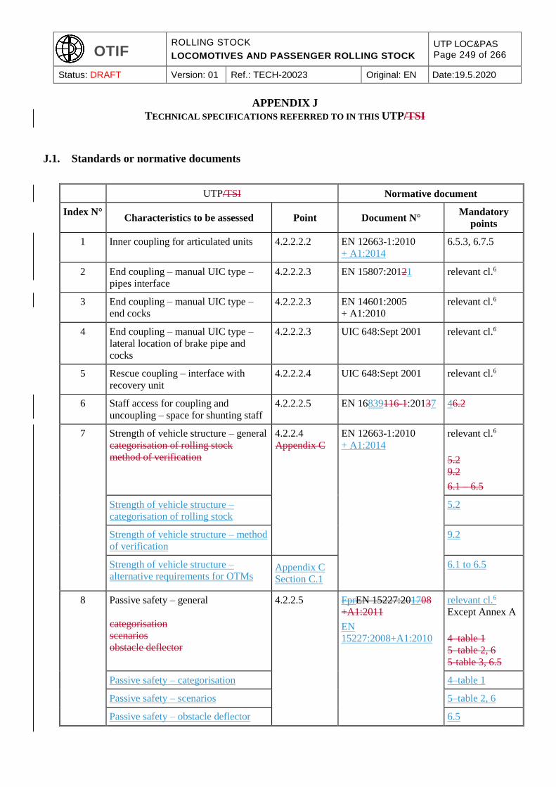
OTIF ROLLING STOCK
LOCOMOTIVES AND PASSENGER ROLLING STOCK
UTP LOC&PAS Page 249 of 266
Status: DRAFT Version: 01 Ref.: TECH-20023 Original: EN Date:19.5.2020
APPENDIX J
TECHNICAL SPECIFICATIONS REFERRED TO IN THIS UTP/TSI
J.1. Standards or normative documents
UTP/TSI Normative document
Index N° Characteristics to be assessed Point Document N°
Mandatory
points
1 Inner coupling for articulated units 4.2.2.2.2 EN 12663-1:2010
+ A1:2014
6.5.3, 6.7.5
2 End coupling – manual UIC type –
pipes interface
4.2.2.2.3 EN 15807:20121 relevant cl.6
3 End coupling – manual UIC type –
end cocks
4.2.2.2.3 EN 14601:2005
+ A1:2010
relevant cl.6
4 End coupling – manual UIC type –
lateral location of brake pipe and
cocks
4.2.2.2.3 UIC 648:Sept 2001 relevant cl.6
5 Rescue coupling – interface with
recovery unit
4.2.2.2.4 UIC 648:Sept 2001 relevant cl.6
6 Staff access for coupling and
uncoupling – space for shunting staff
4.2.2.2.5 EN 16839116-1:20137 46.2
7 Strength of vehicle structure – general
categorisation of rolling stock
method of verification
4.2.2.4
Appendix C
EN 12663-1:2010
+ A1:2014
relevant cl.6
5.2
9.2
6.1 – 6.5
Strength of vehicle structure –
categorisation of rolling stock
5.2
Strength of vehicle structure – method
of verification
9.2
Strength of vehicle structure –
alternative requirements for OTMs Appendix C
Section C.1
6.1 to 6.5
8 Passive safety – general
categorisation
scenarios
obstacle deflector
4.2.2.5 FprEN 15227:201708
+A1:2011
EN
15227:2008+A1:2010
relevant cl.6
Except Annex A
4–table 1
5–table 2, 6
5-table 3, 6.5
Passive safety – categorisation 4–table 1
Passive safety – scenarios 5–table 2, 6
Passive safety – obstacle deflector 6.5
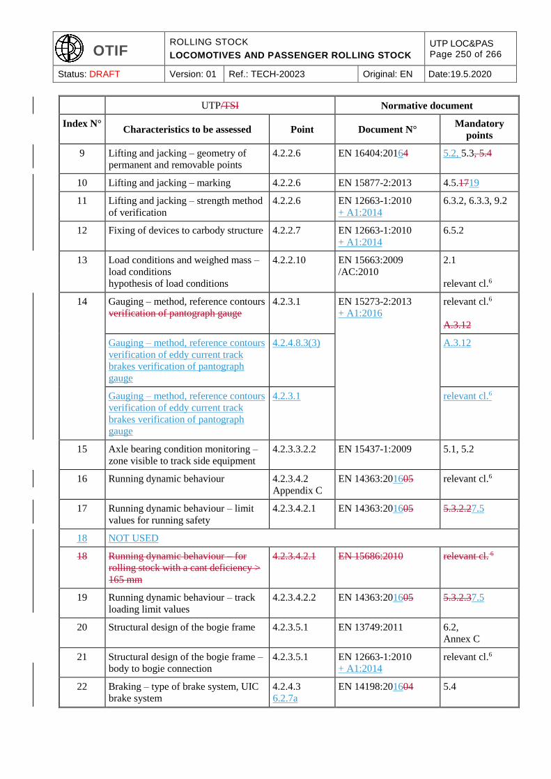
OTIF ROLLING STOCK
LOCOMOTIVES AND PASSENGER ROLLING STOCK
UTP LOC&PAS Page 250 of 266
Status: DRAFT Version: 01 Ref.: TECH-20023 Original: EN Date:19.5.2020
UTP/TSI Normative document
Index N° Characteristics to be assessed Point Document N°
Mandatory
points
9 Lifting and jacking – geometry of
permanent and removable points
4.2.2.6 EN 16404:20164 5.2, 5.3, 5.4
10 Lifting and jacking – marking 4.2.2.6 EN 15877-2:2013 4.5.1719
11 Lifting and jacking – strength method
of verification
4.2.2.6 EN 12663-1:2010
+ A1:2014
6.3.2, 6.3.3, 9.2
12 Fixing of devices to carbody structure 4.2.2.7 EN 12663-1:2010
+ A1:2014
6.5.2
13 Load conditions and weighed mass –
load conditions
hypothesis of load conditions
4.2.2.10 EN 15663:2009
/AC:2010
2.1
relevant cl.6
14 Gauging – method, reference contours
verification of pantograph gauge
4.2.3.1 EN 15273-2:2013
+ A1:2016
relevant cl.6
A.3.12
Gauging – method, reference contours
verification of eddy current track
brakes verification of pantograph
gauge
4.2.4.8.3(3) A.3.12
Gauging – method, reference contours
verification of eddy current track
brakes verification of pantograph
gauge
4.2.3.1 relevant cl.6
15 Axle bearing condition monitoring –
zone visible to track side equipment
4.2.3.3.2.2 EN 15437-1:2009 5.1, 5.2
16 Running dynamic behaviour 4.2.3.4.2
Appendix C
EN 14363:201605 relevant cl.6
17 Running dynamic behaviour – limit
values for running safety
4.2.3.4.2.1 EN 14363:201605 5.3.2.27.5
18 NOT USED
18 Running dynamic behaviour – for
rolling stock with a cant deficiency >
165 mm
4.2.3.4.2.1 EN 15686:2010 relevant cl. 6
19 Running dynamic behaviour – track
loading limit values
4.2.3.4.2.2 EN 14363:201605 5.3.2.37.5
20 Structural design of the bogie frame 4.2.3.5.1 EN 13749:2011 6.2,
Annex C
21 Structural design of the bogie frame –
body to bogie connection
4.2.3.5.1 EN 12663-1:2010
+ A1:2014
relevant cl.6
22 Braking – type of brake system, UIC
brake system
4.2.4.3
6.2.7a
EN 14198:201604 5.4

OTIF ROLLING STOCK
LOCOMOTIVES AND PASSENGER ROLLING STOCK
UTP LOC&PAS Page 251 of 266
Status: DRAFT Version: 01 Ref.: TECH-20023 Original: EN Date:19.5.2020
UTP/TSI Normative document
Index N° Characteristics to be assessed Point Document N°
Mandatory
points
23 Braking performance – calculation –
general
4.2.4.5.1 EN 14531-1:2005 or
EN 14531-6:2009
relevant cl.6
24 Braking performance – friction
coefficient
4.2.4.5.1 EN 14531-1:2005 5.3.1.4
25 Emergency braking performance –
response time / delay time
brake weight percentage
4.2.4.5.2 EN 14531-1:2005 5.3.3
5.12
Emergency braking performance –
brake weight percentage
5.12
26 Emergency braking performance –
calculation
4.2.4.5.2 EN 14531-1:2005 or
EN 14531-6:2009
relevant cl.6
27 Emergency braking performance –
friction coefficient
4.2.4.5.2 EN 14531-1:2005 5.3.1.4
28 Service braking performance –
calculation
4.2.4.5.3 EN 14531-1:2005 or
EN 14531-6:2009
relevant cl.6
29 Parking brake performance –
calculation
4.2.4.5.5 EN 14531-1:2005 or
EN 14531-6:2009
relevant cl.6
30 Wheel slide protection system –
design
verification method
wheel rotation monitoring system
4.2.4.6.2 EN 15595:2009
+ A1:2011
4
5, 6
4.2.4.3
Wheel slide protection system –
verification method
5, 6
Wheel slide protection system – wheel
rotation monitoring system
4.2.4.3
31 Magnetic track brake 4.2.4.8.2 EN 16207:2014UIC
541-06:Jan 1992
Annex Cppendix
3
32 Door obstacle detection – sensitivity
maximum force
4.2.5.5.3 FprEN 14752:20145 5.2.1.4.1
5.2.1.4.2.2
Door obstacle detection – maximum
force
5.2.1.4.2.2
33 Door emergency opening – manual
force to open the door
4.2.5.5.9 FprEN 14752:20154 5.5.1.5
34 Environmental conditions –
temperature
4.2.6.1.1 EN 50125-1:20141999 4.3
35 Environmental conditions – snow, ice
and hail conditions
4.2.6.1.2 EN 50125-1:20141999 4.7
36 Environmental conditions – obstacle
deflector
4.2.6.1.2 EN 15227:2008
+A1:20112010
relevant cl.6

OTIF ROLLING STOCK
LOCOMOTIVES AND PASSENGER ROLLING STOCK
UTP LOC&PAS Page 252 of 266
Status: DRAFT Version: 01 Ref.: TECH-20023 Original: EN Date:19.5.2020
UTP/TSI Normative document
Index N° Characteristics to be assessed Point Document N°
Mandatory
points
37 Aerodynamic effects – crosswind
method of verification
4.2.6.2.4 EN 14067-6:2010 5
38 Head lights – colour
dimmed headlamp luminous intensity
full-beam headlamp luminous
intensity alignment
4.2.7.1.1 EN 15153-1:2013
+ A1:2016
5.3.4
5.3.35 table 2
first line
5.3.5 table 2 first
line
Head lights – dimmed headlamp
luminous intensity
5.3.4 table 2 first
line
Head lights – full-beam headlamp
luminous intensity
5.3.4 table 2 first
line
Head lights – alignment 5.3.5
39 Marker lights – colour
spectral radiation distribution
luminous intensity
4.2.7.1.2 EN 15153-1:2013
+ A1:2016
5.4.34.1 table 4
5.4.4.2
5.4.5
table 6
Marker lights – spectral radiation
distribution
5.4.3.2
Marker lights – luminous intensity 5.4.4 table 6
40 Tail lights – colour
luminous intensity
4.2.7.1.3 EN 15153-1:2013
+ A1:2016
5.5.34 table 7
5.5.5
table 8
Tail lights – luminous intensity 5.5.4 table 8
41 Warning horn sound pressure levels 4.2.7.2.2 EN 15153-2:2013 5.2.2
42 Regenerative brake with energy to the
overhead contact line
4.2.8.2.3 EN 50388:2012 and EN
50388:2012/AC:2013
12.1.1
43 Maximum power and current from the
overhead contact line – automatic
regulation of current
4.2.8.2.4 EN 50388:2012 and EN
50388:2012/AC:2013
7.2
44 Power factor – verification method 4.2.8.2.6 EN 50388:2012 and EN
50388:2012/AC:2013
6
45 System energy disturbances for AC
systems – harmonics and dynamic
effects
compatibility study
4.2.8.2.7 EN 50388:2012 and EN
50388:2012/AC:2013
10.1
10.3
Table 5
Annex D
10.4
System energy disturbances for AC
systems – compatibility study
10.3
Table 5
Annex D
10.4
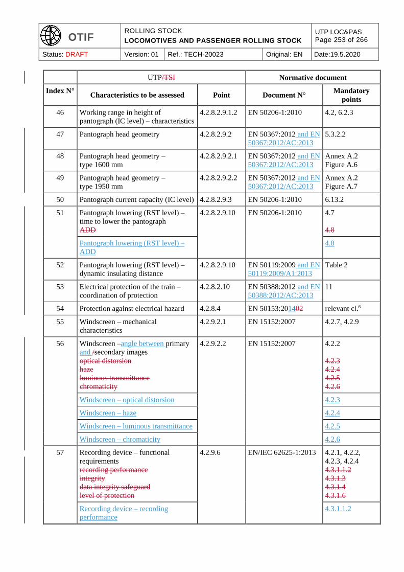
OTIF ROLLING STOCK
LOCOMOTIVES AND PASSENGER ROLLING STOCK
UTP LOC&PAS Page 253 of 266
Status: DRAFT Version: 01 Ref.: TECH-20023 Original: EN Date:19.5.2020
UTP/TSI Normative document
Index N° Characteristics to be assessed Point Document N°
Mandatory
points
46 Working range in height of
pantograph (IC level) – characteristics
4.2.8.2.9.1.2 EN 50206-1:2010 4.2, 6.2.3
47 Pantograph head geometry 4.2.8.2.9.2 EN 50367:2012 and EN
50367:2012/AC:2013
5.3.2.2
48 Pantograph head geometry –
type 1600 mm
4.2.8.2.9.2.1 EN 50367:2012 and EN
50367:2012/AC:2013
Annex A.2
Figure A.6
49 Pantograph head geometry –
type 1950 mm
4.2.8.2.9.2.2 EN 50367:2012 and EN
50367:2012/AC:2013
Annex A.2
Figure A.7
50 Pantograph current capacity (IC level) 4.2.8.2.9.3 EN 50206-1:2010 6.13.2
51 Pantograph lowering (RST level) –
time to lower the pantograph
ADD
4.2.8.2.9.10 EN 50206-1:2010 4.7
4.8
Pantograph lowering (RST level) –
ADD
4.8
52 Pantograph lowering (RST level) –
dynamic insulating distance
4.2.8.2.9.10 EN 50119:2009 and EN
50119:2009/A1:2013
Table 2
53 Electrical protection of the train –
coordination of protection
4.2.8.2.10 EN 50388:2012 and EN
50388:2012/AC:2013
11
54 Protection against electrical hazard 4.2.8.4 EN 50153:201402 relevant cl.6
55 Windscreen – mechanical
characteristics
4.2.9.2.1 EN 15152:2007 4.2.7, 4.2.9
56 Windscreen –angle between primary
and /secondary images
optical distorsion
haze
luminous transmittance
chromaticity
4.2.9.2.2 EN 15152:2007 4.2.2
4.2.3
4.2.4
4.2.5
4.2.6
Windscreen – optical distorsion 4.2.3
Windscreen – haze 4.2.4
Windscreen – luminous transmittance 4.2.5
Windscreen – chromaticity 4.2.6
57 Recording device – functional
requirements
recording performance
integrity
data integrity safeguard
level of protection
4.2.9.6 EN/IEC 62625-1:2013 4.2.1, 4.2.2,
4.2.3, 4.2.4
4.3.1.1.2
4.3.1.3
4.3.1.4
4.3.1.6
Recording device – recording
performance
4.3.1.1.2

OTIF ROLLING STOCK
LOCOMOTIVES AND PASSENGER ROLLING STOCK
UTP LOC&PAS Page 254 of 266
Status: DRAFT Version: 01 Ref.: TECH-20023 Original: EN Date:19.5.2020
UTP/TSI Normative document
Index N° Characteristics to be assessed Point Document N°
Mandatory
points
Recording device – integrity 4.3.1.4
Recording device – data integrity
safeguard
4.3.1.5
Recording device – level of protection 4.3.1.7
58 Measures to prevent fire – material
requirements
4.2.10.2.1 EN 45545-2:2013
+ A1:2015
relevant cl.6
59 Specific measures for flammable
liquids
4.2.10.2.2 EN 45545-2:2013
+ A1:2015
Table 5
60 Fire spreading protection measures for
passenger rolling stock – partition test
4.2.10.3.4 EN 1363-1:20121999 relevant cl.6
61 Fire spreading protection measures for
passenger rolling stock – partition test
4.2.10.3.5 EN 1363-1: 20121999 relevant cl.6
62 Emergency lighting – lighting level 4.2.10.4.1 EN 13272:2012 5.3
63 Running capability 4.2.10.4.4 EN 50553:2012 and EN
50553:2012/AC:2013
relevant cl.6
64 Interface for water filling 4.2.11.5 EN 16362:2013 4.1.2
figure 1
65 Special requirements for stabling of
trains – local external auxiliary power
supply
4.2.11.6 EN/IEC 60309-2:1999
and amendments EN
60309-
2:1999/A11:2004, A1:
2007 and A2:2012
relevant cl.6
66 Automatic centre buffer coupler –
type 10
5.3.1 EN 16019:2014 relevant cl.6
67 Manual end coupling – UIC type 5.3.2 EN 15551:201709 relevant cl.6
68 Manual end coupling – UIC type 5.3.2 EN 15566:201609 relevant cl.6
69 Rescue coupler 5.3.3 EN 15020:2006
+A1:2010
relevant cl.6
70 Main circuit breaker – coordination of
protection
5.3.12 EN 50388:2012 and EN
50388:2012/AC:2013
11
71 Wheels – verification method
decision criteria
further verification method
thermomechanical behaviour
6.1.3.1 EN 13979-1:2003
+A2:2011
7.2.1, 7.2.2
7.2.3
7.3
6
Wheels – verification method
Further verification method
7.3
Wheels – verification method
Thermomechanical behaviour
6
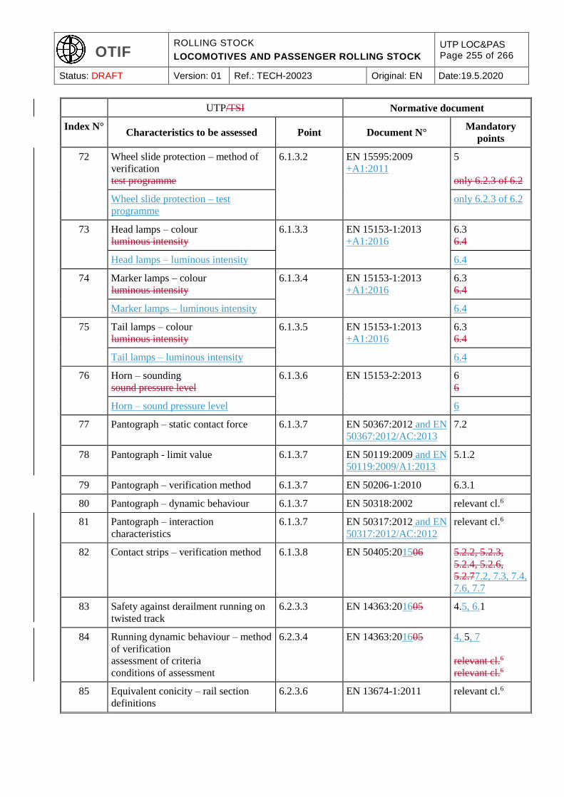
OTIF ROLLING STOCK
LOCOMOTIVES AND PASSENGER ROLLING STOCK
UTP LOC&PAS Page 255 of 266
Status: DRAFT Version: 01 Ref.: TECH-20023 Original: EN Date:19.5.2020
UTP/TSI Normative document
Index N° Characteristics to be assessed Point Document N°
Mandatory
points
72 Wheel slide protection – method of
verification
test programme
6.1.3.2 EN 15595:2009
+A1:2011
5
only 6.2.3 of 6.2
Wheel slide protection – test
programme
only 6.2.3 of 6.2
73 Head lamps – colour
luminous intensity
6.1.3.3 EN 15153-1:2013
+A1:2016
6.3
6.4
Head lamps – luminous intensity 6.4
74 Marker lamps – colour
luminous intensity
6.1.3.4 EN 15153-1:2013
+A1:2016
6.3
6.4
Marker lamps – luminous intensity 6.4
75 Tail lamps – colour
luminous intensity
6.1.3.5 EN 15153-1:2013
+A1:2016
6.3
6.4
Tail lamps – luminous intensity 6.4
76 Horn – sounding
sound pressure level
6.1.3.6 EN 15153-2:2013 6
6
Horn – sound pressure level 6
77 Pantograph – static contact force 6.1.3.7 EN 50367:2012 and EN
50367:2012/AC:2013
7.2
78 Pantograph - limit value 6.1.3.7 EN 50119:2009 and EN
50119:2009/A1:2013
5.1.2
79 Pantograph – verification method 6.1.3.7 EN 50206-1:2010 6.3.1
80 Pantograph – dynamic behaviour 6.1.3.7 EN 50318:2002 relevant cl.6
81 Pantograph – interaction
characteristics
6.1.3.7 EN 50317:2012 and EN
50317:2012/AC:2012
relevant cl.6
82 Contact strips – verification method 6.1.3.8 EN 50405:201506 5.2.2, 5.2.3,
5.2.4, 5.2.6,
5.2.77.2, 7.3, 7.4,
7.6, 7.7
83 Safety against derailment running on
twisted track
6.2.3.3 EN 14363:201605 4.5, 6.1
84 Running dynamic behaviour – method
of verification
assessment of criteria
conditions of assessment
6.2.3.4 EN 14363:201605 4, 5, 7
relevant cl.6
relevant cl.6
85 Equivalent conicity – rail section
definitions
6.2.3.6 EN 13674-1:2011 relevant cl.6
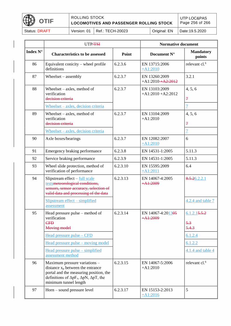
OTIF ROLLING STOCK
LOCOMOTIVES AND PASSENGER ROLLING STOCK
UTP LOC&PAS Page 256 of 266
Status: DRAFT Version: 01 Ref.: TECH-20023 Original: EN Date:19.5.2020
UTP/TSI Normative document
Index N° Characteristics to be assessed Point Document N°
Mandatory
points
86 Equivalent conicity – wheel profile
definitions
6.2.3.6 EN 13715:2006
+A1:2010
relevant cl.6
87 Wheelset – assembly 6.2.3.7 EN 13260:2009
+A1:2010 +A2:2012
3.2.1
88 Wheelset – axles, method of
verification
decision criteria
6.2.3.7 EN 13103:2009
+A1:2010 +A2:2012
4, 5, 6
7
Wheelset – axles, decision criteria 7
89 Wheelset – axles, method of
verification
decision criteria
6.2.3.7 EN 13104:2009
+A1:2010
4, 5, 6
7
Wheelset – axles, decision criteria 7
90 Axle boxes/bearings 6.2.3.7 EN 12082:2007
+A1:2010
6
91 Emergency braking performance 6.2.3.8 EN 14531-1:2005 5.11.3
92 Service braking performance 6.2.3.9 EN 14531-1:2005 5.11.3
93 Wheel slide protection, method of
verification of performance
6.2.3.10 EN 15595:2009
+A1:2011
6.4
94 Slipstream effect – full scale
testsmeteorological conditions,
sensors, sensor accuracy, selection of
valid data and processing of the data
6.2.3.13 EN 14067-4:2005
+A1:2009
8.5.26.2.2.1
Slipstream effect – simplified
assessment
4.2.4 and table 7
95 Head pressure pulse – method of
verification
CFD
Moving model
6.2.3.14 EN 14067-4:201305
+A1:2009
6.1.2.15.5.2
5.3
5.4.3
Head pressure pulse – CFD 6.1.2.4
Head pressure pulse – moving model 6.1.2.2
Head pressure pulse – simplified
assessment method
4.1.4 and table 4
96 Maximum pressure variations –
distance xp between the entrance
portal and the measuring position, the
definitions of ΔpFr, ΔpN, ΔpT, the
minimum tunnel length
6.2.3.15 EN 14067-5:2006
+A1:2010
relevant cl.6
97 Horn – sound pressure level 6.2.3.17 EN 15153-2:2013
+A1:2016
5
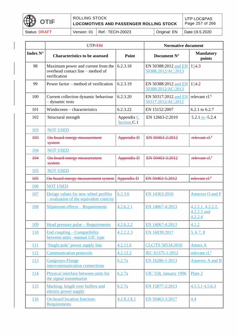
OTIF ROLLING STOCK
LOCOMOTIVES AND PASSENGER ROLLING STOCK
UTP LOC&PAS Page 257 of 266
Status: DRAFT Version: 01 Ref.: TECH-20023 Original: EN Date:19.5.2020
UTP/TSI Normative document
Index N° Characteristics to be assessed Point Document N°
Mandatory
points
98 Maximum power and current from the
overhead contact line – method of
verification
6.2.3.18 EN 50388:2012 and EN
50388:2012/AC:2013
154.3
99 Power factor – method of verification 6.2.3.19 EN 50388:2012 and EN
50388:2012/AC:2013
154.2
100 Current collection dynamic behaviour
– dynamic tests
6.2.3.20 EN 50317:2012 and EN
50317:2012/AC:2012
relevant cl.6
101 Windscreen – characteristics 6.2.3.22 EN 15152:2007 6.2.1 to 6.2.7
102 Structural strength Appendix C
Section C.1
EN 12663-2:2010 5.2.1 to -5.2.4
103 NOT USED
103 On-board energy measurement
system
Appendix D EN 50463-2:2012 relevant cl.6
104 NOT USED
104 On-board energy measurement
system
Appendix D EN 50463-3:2012 relevant cl.6
105 NOT USED
105 On-board energy measurement system Appendix D EN 50463-5:2012 relevant cl.6
106 NOT USED
107 Design values for new wheel profiles
– evaluation of the equivalent conicity
6.2.3.6 EN 14363:2016 Annexes O and P
108 Slipstream effects – Requirements 4.2.6.2.1 EN 14067-4:2013 4.2.2.1, 4.2.2.2,
4.2.2.3 and
4.2.2.4
109 Head pressure pulse – Requirements 4.2.6.2.2 EN 14067-4:2013 4.1.2
110 End coupling – Compatibility
between units –manual UIC type
4.2.2.2.3 EN 16839:2017 5, 6 7, 8
111 ‘Single pole’ power supply line 4.2.11.6 CLC/TS 50534:2010 Annex A
112 Communication protocols 4.2.12.2 IEC 61375-1:2012 relevant cl.6
113 Gangways-Flange
intercommunication connections
6.2.7a EN 16286-1:2013 Annexes A and B
114 Physical interface between units for
the signal transmission
6.2.7a UIC 558, January 1996 Plate 2
115 Marking: length over buffers and
electric power supply
6.2.7a EN 15877-2:2013 4.5.5.1 4.5.6.3
116 On-board location function-
Requirements
4.2.8.2.8.1 EN 50463-3:2017 4.4
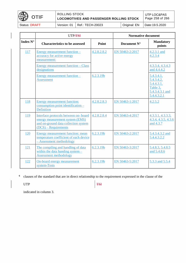
OTIF ROLLING STOCK
LOCOMOTIVES AND PASSENGER ROLLING STOCK
UTP LOC&PAS Page 258 of 266
Status: DRAFT Version: 01 Ref.: TECH-20023 Original: EN Date:19.5.2020
UTP/TSI Normative document
Index N° Characteristics to be assessed Point Document N°
Mandatory
points
117 Energy measurement function –
accuracy for active energy
measurement:
4.2.8.2.8.2 EN 50463-2:2017 4.2.3.1 and
4.2.3.4
Energy measurement function – Class
designations
4.3.3.4, 4.3.4.3
and 4.4.4.2
Energy measurement function –
Assessment
6.2.3.19b 5.4.3.4.1,
5.4.3.4.2,
5.4.4.3.1,
Table 3,
5.4.3.4.3.1 and
5.4.4.3.2.1
118 Energy measurement function:
consumption point identification –
Definition
4.2.8.2.8.3 EN 50463-1:2017 4.2.5.2
119 Interface protocols between on- board
energy measurement system (EMS)
and on-ground data collection system
(DCS) – Requirements
4.2.8.2.8.4 EN 50463-4:2017 4.3.3.1, 4.3.3.3,
4.3.4, 4.3.5, 4.3.6
and 4.3.7
120 Energy measurement function: mean
temperature coefficient of each device
– Assessment methodology
6.2.3.19b EN 50463-2:2017 5.4.3.4.3.2 and
5.4.4.3.2.2
121 The compiling and handling of data
within the data handing system –
Assessment methodology
6.2.3.19b EN 50463-3:2017 5.4.8.3, 5.4.8.5
and 5.4.8.6
122 On-board energy measurement
system-Tests
6.2.3.19b EN 50463-5:2017 5.3.3 and 5.5.4
6 clauses of the standard that are in direct relationship to the requirement expressed in the clause of the
UTP TSI
indicated in column 3.
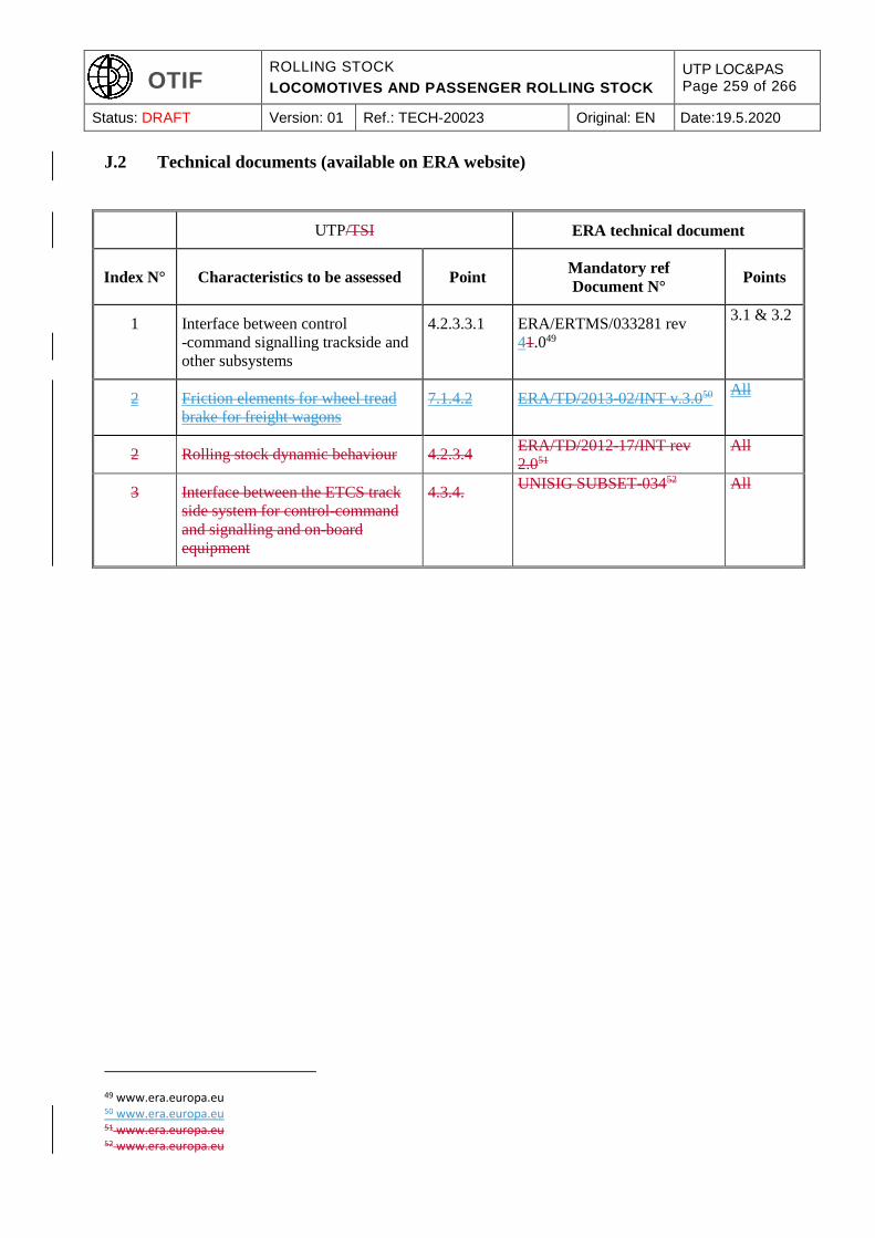
OTIF ROLLING STOCK
LOCOMOTIVES AND PASSENGER ROLLING STOCK
UTP LOC&PAS Page 259 of 266
Status: DRAFT Version: 01 Ref.: TECH-20023 Original: EN Date:19.5.2020
J.2 Technical documents (available on ERA website)
UTP/TSI ERA technical document
Index N° Characteristics to be assessed Point Mandatory ref
Document N° Points
1 Interface between control
-command signalling trackside and
other subsystems
4.2.3.3.1 ERA/ERTMS/033281 rev
41.049
3.1 & 3.2
2 Friction elements for wheel tread
brake for freight wagons
7.1.4.2 ERA/TD/2013-02/INT v.3.050 All
2 Rolling stock dynamic behaviour 4.2.3.4 ERA/TD/2012-17/INT rev
2.051
All
3 Interface between the ETCS track
side system for control-command
and signalling and on-board
equipment
4.3.4. UNISIG SUBSET-03452 All
49 www.era.europa.eu 50 www.era.europa.eu 51 www.era.europa.eu 52 www.era.europa.eu
OTIF ROLLING STOCK
LOCOMOTIVES AND PASSENGER ROLLING STOCK
UTP LOC&PAS Page 260 of 266
Status: DRAFT Version: 01 Ref.: TECH-20023 Original: EN Date:19.5.2020
APPENDIX K
PROVISIONS FOR THE SAFE OPERATION OF ROLLING STOCK
The provisions in this appendix are related to the correct operation of rolling stock within its conditions
and limits of use. This appendix has no equivalence in the LOC&PAS TSI, because in the EU specific
provisions are set out in the OPE TSI. This appendix is foreseen to be repealed at the moment that a UTP
OPE enters into force.
Documentation for drivers
The railway undertaking operating the train must
supply the driver with all the necessary
information and documentation required to carry
out his duties. This information must take into
account the necessary elements for operation in
normal, degraded and emergency situations for
the routes to be worked over and the rolling stock
used on those routes.
(53)
4.2.1.2. Documentation for drivers
The railway undertaking operating the train must
supply the driver with all the necessary
information and documentation required to carry
out his duties.
This information must take into account the
necessary elements for operation in normal,
degraded and emergency situations for the routes
to be worked over and the rolling stock used on
those routes.
Documentation for railway undertaking staff
other than drivers
The railway undertaking operating the train must
supply all members of its staff (whether on the
train or otherwise) who undertake safety-critical
tasks with all the rolling stock specific
information it deems appropriate to such tasks.
Such information shall be applicable in both
normal and degraded operation.
4.2.1.3. Documentation for railway undertaking
staff other than drivers
The railway undertaking must provide all
members of his staff (whether on train or
otherwise) who undertake safety-critical tasks
involving a direct interface with the staff,
equipment or systems of the infrastructure
manager with the rules, procedures, rolling stock
and route specific information it deems
appropriate to such tasks. Such information shall
be applicable in both normal and degraded
operation.
Knowledge of rolling stock
A process must be defined to ensure the acquisition
and retention of vehicle knowledge by the train
crew.
4.6.3.2.3.2. Knowledge of rolling stock
The railway undertaking must define the process
for the acquisition and retention of traction and
rolling stock knowledge by its train crew.
Front end Where a coach is used as the front end of a train,
the railway undertaking operating the train must
provide the means of indicating the front end of a
train in compliance with the rules of the network
on which the train is operated.
4.2.2.1.2. Front end
The railway undertaking must ensure that an
approaching train is clearly visible and
recognisable as such, by the presence and layout
of its lit white front-end lights.
53 The corresponding EU requirements are set out in Commission Decision of 14 November 2012 concerning the technical specification for interoperability relating to the ‘operation and traffic management’ subsystem of the rail system in the European Union and amending Decision 2007/756/EC (2012/757/EC (OPE TSI)) OJ L 345, 15.12.2012.

OTIF ROLLING STOCK
LOCOMOTIVES AND PASSENGER ROLLING STOCK
UTP LOC&PAS Page 261 of 266
Status: DRAFT Version: 01 Ref.: TECH-20023 Original: EN Date:19.5.2020
The forward facing front end of the leading
vehicle of a train must be fitted with three lights in
an isosceles triangle, as shown below. These
lights must always be lit when the train is being
driven from that end.
The forward facing front-end of the leading
vehicle of a train must be fitted with three lights in
an isosceles triangle, as shown below. These
lights must always be lit when the train is being
driven from that end.
The front lights must optimise train detectability (for
example, for track workers and those using public
crossings) (marker lights), provide sufficient
visibility for the train driver (illumination of the line
ahead, lineside information markers/boards, etc.)
(head lights) by night and during low light conditions
and must not dazzle the drivers of oncoming trains.
The spacing, the height above rails, the colour and
intensity of the lights, the dimensions and shape of
the emitted beam are defined in clauses 4.2.7.1.1 and
4.2.7.1.2.
The front lights must optimise train detectability
(for example, to track workers and those using
public crossings) (marker lights), provide
sufficient visibility for the train driver
(illumination of the line ahead, lineside
information markers/boards, etc.) (head lights)
by night and during low light conditions and must
not dazzle the drivers of oncoming trains.
The spacing, the height above rails, the diameter,
the intensity of the lights, the dimensions and
shape of the emitted beam in both day and night
time operation are defined in the rolling stock
TSI(hereinafter referred to as ‘RST TSI’).
Rear end
The railway undertaking operating the train must
provide the required means of indicating the rear of
a train in compliance with the rules of the network
on which the vehicle is operated. The rear end signal
must only be exhibited on the rear of the last vehicle
of the train.
The spacing, the height above rails, the colour and
intensity of the tail lights, the dimensions and shape
of the emitted beam are defined in clause 4.2.7.1.3
4.2.2.1.3. Rear end
The railway undertaking must provide the
required means of indicating the rear of a train.
4.2.2.1.3.1 Passenger trains
The rear end indication of a passenger train must
consist of 2 steady red lights at the same height
above buffer on the transversal axis.
Safety of passengers 4.2.2.4.2. Safety of passengers
OTIF ROLLING STOCK
LOCOMOTIVES AND PASSENGER ROLLING STOCK
UTP LOC&PAS Page 262 of 266
Status: DRAFT Version: 01 Ref.: TECH-20023 Original: EN Date:19.5.2020
The railway undertaking operating the train must
ensure that passenger transport is undertaken safely
at the departure and during the journey.
The railway undertaking must ensure that
passenger transport is undertaken safely at the
departure and during the journey.
Train composition
Train composition shall be the responsibility of the
railway undertaking. Rules and procedures shall be
defined which must be followed by the staff so as to
ensure that the train complies with the allocated
path.
UTP PRM requirements must be taken into account
in train composition.
Train composition requirements must also take into
account the following elements:
a) the vehicles
all vehicles in the train must comply with all
the requirements applicable on the routes over
which the train will run;
all vehicles on the train must be fit to run at
the maximum speed at which the train is
scheduled to run;
b) all vehicles on the train must currently be within
their specified maintenance interval and remain
so for the duration (in terms of both time and
distance) of the journey being undertaken;
c) the train
the combination of vehicles forming a train
must comply with the technical constraints of the
route concerned and be within the maximum
length permissible for forwarding and receiving
terminals.
d) the railway undertaking is responsible for
ensuring that the train is technically fit for the
journey to be undertaken and remains so
throughout the journey.
e) the weight and axle load
f) the weight of the train must be within the
maximum permissible for the section of route,
the strength of the couplings, the traction power
and other relevant characteristics of the train.
Axle load limitations must be respected.
g) the maximum speed of the train
the maximum speed at which the train can run
must take into account any restrictions on the
4.2.2.5. Train composition
The railway undertaking must define the rules
and procedures to be followed by his staff so as
to ensure that the train is in compliance with the
allocated path.
Train composition requirements must take into
account the following elements:
a) the vehicles
all vehicles in the train must be in
compliance with all the requirements
applicable on the routes over which the train
will run;
all vehicles on the train must be fit to run
at the maximum speed at which the train is
scheduled to run;
b) all vehicles on the train must be currently
within their specified maintenance interval
and will remain so for the duration (in terms
of both time and distance) of the journey
being undertaken;
c) the train
the combination of vehicles forming a
train must comply with the technical
constraints of the route concerned and be
within the maximum length permissible for
forwarding and receiving terminals.
d) the railway undertaking is responsible for
ensuring that the train is technically fit for the
journey to be undertaken and remains so
throughout the journey.
e) the weight and axle load
f) the weight of the train must be within the
maximum permissible for the section of route,
the strength of the couplings, the traction
power and other relevant characteristics of
the train. Axle load limitations must be
respected.
g) the maximum speed of the train
the maximum speed at which the train can
run must take into account any restrictions on
OTIF ROLLING STOCK
LOCOMOTIVES AND PASSENGER ROLLING STOCK
UTP LOC&PAS Page 263 of 266
Status: DRAFT Version: 01 Ref.: TECH-20023 Original: EN Date:19.5.2020
route(s) concerned, braking performance, axle
load and vehicle type.
h) the kinematic envelope
i) the kinematic gauge of each vehicle (inclusive of
any load) in the train must be within the
maximum permissible for the section of route.
the route(s) concerned, braking performance,
axle load and vehicle type.
h) the kinematic envelope
i) the kinematic gauge of each vehicle (inclusive
of any load) in the train must be within the
maximum permissible for the section of route.
Minimum requirements of the braking system,
Braking performance
All vehicles in a train must be connected to the
continuous braking system. The first and last
vehicles in any train must have the automatic brake
operative54. The railway undertaking operating the
train must ensure that the train meets the required
braking performance.
4.2.2.6.1. Minimum requirements of the braking
system
All vehicles in a train must be connected to the
continuous automatic braking system as defined
in the TSI Rolling Stock
The first and last vehicles (including any traction
units) in any train must have the automatic brake
operative.
4.2.2.6.2. Braking performance
The infrastructure manager must provide the
railway undertaking with the actual
performance required. This data shall
include, if necessary, conditions of use of
braking systems possibly affecting the
infrastructure such as magnetic, regenerative
and eddy-current brake.
General requirement that the train is in running
order
Processes shall be defined, which must be followed
by the railway undertaking, to ensure that all safety-
related on-train equipment is in a fully functional
state and that the train is safe to run. In case of
modification to the characteristics of the train
affecting the ability to accommodate the train in its
allocated path, procedures for running in degraded
mode shall be defined.
The railway undertaking shall inform the
infrastructure manager of any change which affects
the performance of the train, or which may affect the
ability to accommodate the train in its allocated
path.
4.2.2.7.1. General requirement that the train is in
running order
The railway undertaking must define the process
to ensure that all safety-related on-train
equipment is in a fully functional state and that
the train is safe to run.
The railway undertaking must inform the
infrastructure manager of any modification to the
characteristics of the train affecting its
performance or any modification that might
affect the ability to accommodate the train in its
allocated path.
The infrastructure manager and the railway
undertaking must define and keep up to date
conditions and procedures for train running in
degraded mode.
Driver vigilance
A means of onboard monitoring of driver vigilance
is necessary. This shall intervene to bring the train to
4.2.2.9. Driver vigilance
A means of onboard monitoring of driver
vigilance is necessary. This shall intervene to
54 In operation / in working order / functioning
OTIF ROLLING STOCK
LOCOMOTIVES AND PASSENGER ROLLING STOCK
UTP LOC&PAS Page 264 of 266
Status: DRAFT Version: 01 Ref.: TECH-20023 Original: EN Date:19.5.2020
a standstill if the driver does not react within a
certain time.
bring the train to a stand if the driver does not
react within a certain time.
Checks and tests before departure
Checks shall be defined which must be followed by
the railway undertaking to ensure that any departure
is undertaken safely (e.g. doors, load, brakes).
4.2.3.3.1. Checks and tests before departure
The railway undertaking must define the checks
and tests to ensure that any departure is
undertaken safely (e.g. doors, load, brakes).
Degraded operation
Before operating on a network, the railway
undertaking shall have procedures in place to be
informed of and deal with situations of degraded
operation.
These procedures shall enable the railway
undertaking to:
advise the infrastructure manager so that it
can inform other users of the network
process information received from the
infrastructure manager to its own train
drivers with respect to degraded operations.
Appropriate contingency measures shall be defined,
published and made available.
4.2.3.6. Degraded operation
4.2.3.6.1. Advice to other users
The infrastructure manager in conjunction with
the railway undertaking(s) must define a process
to immediately inform each other of any situation
that impedes the safety, performance and/or the
availability of the rail network or rolling stock.
4.2.3.6.2. Advice to train drivers
In any case of degraded operation associated
with the infrastructure manager’s area of
responsibility, the infrastructure manager must
give formal instructions to drivers on what
measures to take in order to safely overcome the
degradation.
4.2.3.6.3. Contingency arrangements
The infrastructure manager in conjunction with
all the railway undertakings operating over his
infrastructure, and neighbouring infrastructure
managers as appropriate, must define, publish
and make available appropriate contingency
measures and assign responsibilities based on
the requirement to reduce any negative impact as
a result of degraded operation.
The planning requirements and the response to
such events must be proportional to the nature
and potential severity of the degradation.
These measures, which must as a minimum
include plans for recovering the network to
‘normal’ status, may also address:
— rolling stock failures (for example, those
which could result in substantial traffic
disruption, the procedures for rescuing failed
trains);
— infrastructure failures (for example, when
there has been a failure of the electric power or
the conditions under which trains may be
diverted from the booked route);
— extreme weather conditions.
The infrastructure manager must establish and
keep updated contact information for key
infrastructure manager and railway undertaking
OTIF ROLLING STOCK
LOCOMOTIVES AND PASSENGER ROLLING STOCK
UTP LOC&PAS Page 265 of 266
Status: DRAFT Version: 01 Ref.: TECH-20023 Original: EN Date:19.5.2020
staff who may be contacted in the event of service
disruption leading to degraded operation. This
information must include contact details both
during and outside office hours.
The railway undertaking must submit this
information to the infrastructure manager and
advise the infrastructure manager of any changes
to these contact details.
The infrastructure manager must advise all the
railway undertaking(s) of any changes to his
details.
Managing an emergency situation
Before operating on a network, the railway
undertaking shall have procedures in place to act
appropriately in an emergency situation.
To this end the railway undertaking shall cooperate
with authorities, other railway undertakings and the
infrastructure manager to establish appropriate
measures to manage emergency situations and
restore the line to normal operation.
Such emergency situations shall typically cover:
— collisions,
— fires on train,
— evacuation of trains,
— accidents in tunnels,
— incidents involving dangerous goods,
— derailments.
The railway undertaking must provide the
infrastructure manager with any specific
information in respect of these circumstances,
especially in respect to the recovery or re-railing of
their trains.
Additionally, the railway undertaking must have
processes to inform passengers about on-board
emergency and safety procedures.
4.2.3.7. Managing an emergency situation
The infrastructure manager must, in consultation
with:
— all railway undertakings operating over his
infrastructure, or, where appropriate,
representative bodies of railway undertakings
operating over his infrastructure;
— neighbouring infrastructure managers, as
appropriate;
— local authorities, representative bodies of the
emergency services (including fire fighting and
rescue) at either local or national level, as
appropriate.
define, publish and make available appropriate
measures to manage emergency situations and
restore the line to normal operation.
Such measures shall typically cover:
— collisions,
— fires on train,
— evacuation of trains,
— accidents in tunnels,
— incidents involving dangerous goods,
— derailments.
The railway undertaking must provide the
infrastructure manager with any specific
information in respect to these circumstances,
especially in respect to the recovery or re-railing
of their trains.
Additionally, the railway undertaking must have
processes to inform passengers about on-board
emergency and safety procedures.
Aid to train crew in the event of an incident or of
a major rolling stock malfunction
4.2.3.8. Aid to train crew in the event of an
accident or of a major rolling stock malfunction

OTIF ROLLING STOCK
LOCOMOTIVES AND PASSENGER ROLLING STOCK
UTP LOC&PAS Page 266 of 266
Status: DRAFT Version: 01 Ref.: TECH-20023 Original: EN Date:19.5.2020
Appropriate procedures shall be defined to assist
the train crew in degraded situations in order to
avoid or decrease delays caused by technical or
other failures of the rolling stock (for example, lines
of communication, measures to be taken in case of
evacuation of a train).
The railway undertaking must define appropriate
procedures to assist the train crew in degraded
situations in order to avoid or decrease delays
caused by technical or other failures of the
rolling stock (for example, lines of
communication, measures to be taken in case of
evacuation of a train).