Underwater Sampling of Soils - Online-PDH
38
Underwater Sampling of Soils DISCLAIMER: All course materials available on this website are not to be construed as a representation or warranty on the part of Online-PDH, or other persons and/or organizations named herein. All course literature is for reference purposes only, and should not be used as a substitute for competent, professional engineering council. Use or application of any information herein, should be done so at the discretion of a licensed professional engineer in that given field of expertise. Any person(s) making use of this information, herein, does so at their own risk and assumes any and all liabilities arising therefrom. Copyright © 2009 Online-PDH - All Rights Reserved 1265 San Juan Dr. - Merritt Island, FL 32952 Phone: 321-501-5601 Online Continuing Education for Professional Engineers Since 2009 PDH Credits: 2 PDH Course No.: USS101 Publication Source: US Corps of Engineers “ Geotechnical Investigations, Engineering Manual Chapter F-10, Underwater Sampling of Soils” Pub. # EM 1110-1-1804 Release Date: Jan. 2001
Transcript of Underwater Sampling of Soils - Online-PDH

Underwater Sampling of Soils
DISCLAIMER: All course materials available on this website are not to be construed as a representation or warranty on the part of Online-PDH, or other persons and/or organizations named herein. All course literature is for reference purposes only, and should not be used as a substitute for competent, professional engineering council. Use or application of any information herein, should be done so at the discretion of a licensed professional engineer in that given field of expertise. Any person(s) making use of this information, herein, does so at their own risk and assumes any and all liabilities arising therefrom.
Copyright © 2009 Online-PDH - All Rights Reserved 1265 San Juan Dr. - Merritt Island, FL 32952
Phone: 321-501-5601
Online Continuing Education for Professional Engineers Since 2009
PDH Credits:
2 PDH
Course No.: USS101
Publication Source:
US Corps of Engineers “ Geotechnical Investigations, Engineering Manual
Chapter F-10, Underwater Sampling of Soils” Pub. # EM 1110-1-1804
Release Date:
Jan. 2001
EM 1110-1-18041 Jan 01
F-10-1
Chapter F-10Underwater Sampling of Soils
10-1. Introduction
This chapter is intended to provide guidance for obtaining soil samples in the nearshore environment,such as harbors, rivers, coastal plains, backswamps, and wetlands where the depth of water varies from0 to 45 m (0 to 150 ft), and is generally less than 20 m (65 ft). Sampling in deep water is not addressedherein. This guidance is intended to support typical projects such as marine construction projects,dredging of channels and harbors, construction of levees and dams, and reclamation of wetlands.Therefore, the information concentrates on common, commercially available sampling equipment andmethods. One-of-a-kind research tools or equipment available only from foreign countries is notdiscussed. Appendix A lists references that discuss some of these topics. However, guidance forobtaining chemical samples, which is typically done in conjunction with soil sampling, is beyond thescope of this manual. Geotechnical personnel should coordinate underwater chemical sampling with theProject Environmental Engineer, or should refer to EPA Manual 503/8-91 (the �green book�) and theappropriate Regional Implementation Manual.
Generally, sampling soils underwater in the nearshore environment is not significantly different fromsampling soils on land. The concerns for obtaining minimally disturbed samples for geotechnical testingare the same; the samples are just more difficult to obtain. In addition to the need to find the rightequipment for obtaining samples, a work platform or vessel and a positioning system are needed. Thewind, waves, tides, currents, and water depths must also be considered when planning a siteinvestigation.
The selection of appropriate sampling equipment for retrieving underwater samples depends upon severalfactors: soil data required, sizes of test specimens needed, sediment type, geology, the depth of water orelevation of the seafloor, environmental conditions, vessel availability, and funding limits. These factorsdo not always favor selections that are compatible. For example, the equipment required to obtain thesize and/or quality of sample(s) may not be deployable from the vessel available within the projectbudget, or the available vessel may not be able to operate in the required shallow-water depths. Each ofthese factors will be discussed in this chapter.
10-2. Underwater Sediment Types
The selection of appropriate equipment for underwater sampling depends on the type of sediment to besampled. Because some samplers cannot be used to retrieve a high-quality sample, or in some cases, anysample in certain types of materials, it is important to know beforehand the types of sediments mostlikely to be encountered at the site.
Marine sediments can be classified according to several criteria (Noorany 1989). In the nearshoreenvironment, marine sediments are classified according to their origin. Lithogenous (derived from rock)sediments are formed from terrestrial or volcanic sources. Underwater lithogenous (terrigenous)sediments result either from a rise in the sea level, the submergence of land due to geological events, orby soil particles being transported by wind, water, or ice to the sea where they settle. Because samplingterrigenous sediments is similar to sampling the same types of soils on land, determination of the sourceof the sediments and the method by which the deposit was formed can help in predicting whether thesediment is normally consolidated or overconsolidated; this information can be used as a guide for
EM 1110-1-18041 Jan 01
F-10-2
selecting the best sampling method(s). Biogenic sediments, which are found in both nearshore and deepocean deposits, are formed from the remains of marine organisms. The most common sediments areeither silica (SiO ) or calcium carbonate (CaCO ) materials. Hydrogenic sediments are formed by a2 3chemical reaction that occurs under the right conditions of temperature, pressure (water depth), andchemical content of the water and subsequent precipitation of material. Hydrogenous deposits of calciumcarbonate can be found nearshore in some areas. Unlike the terrigenous sediments, calcium carbonatesediments are particularly difficult to sample without disturbance; additional information is contained inthe proceedings of the international conference on calcareous sediments (Jewell and Khorshid 1988).
10-3. Planning an Underwater Site Investigation
Planning a site investigation on land is discussed in Chapter 2. As compared to an onshore investigation,a nearshore or offshore investigation may encounter some unique problems. To plan an effectiveoffshore investigation, preliminary information should be gathered on the site configuration,environmental conditions, the type of sediment expected to be found at the site, and the samplingequipment and work platforms available and their capabilities. With this information, decisions can bemade regarding where to take samples, how many, and to what depth to meet the project requirements.Information on the expected sediment type and the data needed from the samples will determine the typeof sampler to use.
One of the first steps is to obtain a marine chart of the area to be surveyed. Suitable charts and maps areavailable from the National Ocean Service and the National Oceanic and Atmospheric Administration(NOAA) for coastal and Great Lakes areas, the Defense Mapping Agency for open ocean and foreignwaters, and the U.S. Army Corps of Engineers for inland rivers, lakes, and canal systems; thesedocuments can be purchased at local marine chandlery stores or ordered from the issuing agency. If thesurvey site is close to shore, a topographic map of the adjacent land area may also be very helpful.Marine charts normally will show sediment types, water depths, shipping channels, permanent moorings,bridges, buoys, shoals, underwater cables and pipelines, and other items of interest. Water depths areusually referenced to low-water level, whereas bridge clearances are referenced to high-water levels. Thedate of the chart should be checked and the information on it verified and/or adjusted according to itsage. For example, water depths in a harbor may be less than indicated due to sedimentation.
Prior to the investigation, it is suggested that a site visit should be conducted, if possible, to compare thechart with the actual site conditions. Moorings, piers, or other shoreline construction can affect theplanning of the survey. While at the site, obtain boat traffic patterns, weather conditions, typical waveheights and currents, and other conditions which could affect the survey. The impact of seasonal events,such as sport boating or fishing seasons, and changes in environmental patterns, such as the depositionand erosion of sediments, weather patterns, or the occurrence of fog, should be investigated. Local tidecharts, if applicable, are sometimes available from the harbor master or port services or can be obtainedfrom the National Ocean Service; these charts can be very helpful in planning work for the best use ofdaylight hours and in conjunction with the tides. Public utility companies should be contacted forupdated information if the chart indicates underwater cables or other equipment. The U.S. Coast Guardalso provides updated information to the chart in �Notice to Mariners� information on new hazards andchanges. The location of onshore structures that could block the navigation system operation and siteswhich could be used for the navigation system shore stations should be noted.

EM 1110-1-18041 Jan 01
F-10-3
10-4. Work Platforms for Underwater Sampling
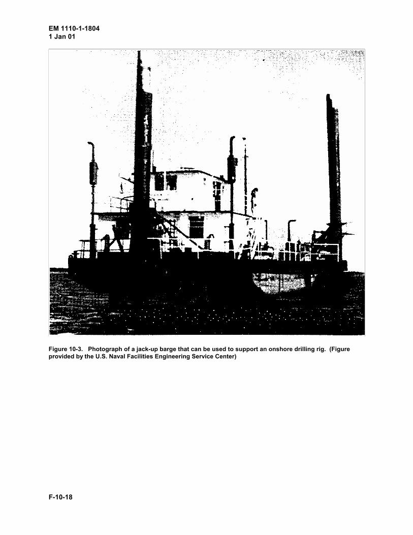
Several types and sizes of work platforms, including scaffolds, barges, and ships, are available to supportunderwater sampling work. When a platform is selected for a site survey, a number of factors should beconsidered. These factors include the effects of tides, currents, and depth of water; the positioning of theplatform and the capabilities for deploying and retrieving the sampler; the type of sampling equipment aswell as the number, size, quality, and depth of samples; safety; and the availability of the equipment.Figure 10-1 shows a small drill rig on a scaffold. Figure 10-2 shows a barge set up for nearshore work.Figure 10-3 shows a jack-up barge that can be used to support an onshore drilling rig. Workboats anddrillships are used for sampling in deeper water. A discussion of each of these factors is presented in thefollowing paragraphs.
When a sampling operation is being planned, site data are needed on maximum and minimum waterdepths, tides, currents, and typical wave heights for the expected weather conditions. The minimumwater depths will determine the draft of the vessel that can be used. The height of the vessel, includingantennae, navigation equipment, and crane boom, will be important if bridges or other obstacles have tobe negotiated.
If samples are required from specified points or locations, then navigation, positioning, and station-keeping systems will affect the type of work platform which is selected. Frequent moves to differentlocations will require a platform that is easily maneuvered and quickly anchored. The positioning systemwill depend on the physical characteristics of the site to be surveyed. Vessels typically have from one tofour anchors, whereas it may be necessary to install temporary anchors and winches on a barge. Somevessels have bow thrusters which allow them to hold a position without anchoring or with only a minimalnumber of anchors. If the navigation system on the vessel cannot provide the accuracy required, a sup-plemental system will have to be employed. With a preplanned investigation, a priority for obtainingsamples and their relative locations will allow a more efficient site survey.
The height, reach, and load capacity of the lifting equipment should be specified. Typical types of liftingequipment include cranes, winches, A-frames, and davits. Figure 10-2 shows a barge with a crane, anA-frame, and a winch. The vertical and horizontal clearances for an A-frame should be known becausethe horizontal clearance varies from the top to the bottom of the A-frame. Figure 10-4 shows a samplingdevice hung from a pair of davits along the side of a vessel; it can be deployed with winches. Figure10-5 shows a sampler deployed with a mobile crane mounted on a barge. Because of insufficient deckspace, the head of the corer was supported overwater by the crane while its base was placed on the deckas the core was removed.
The support requirements for the sampling device such as power, compressed air, water flow andpressure, deck space and lifting capacity to deploy and retrieve the sampler, and core handling andstorage space, need to be considered when the work platform is selected. For example, the type ofsampling device should be selected based upon the quality, diameter, and depth of samples needed.However, if the work platform does not have the required support equipment, such as an internal powersource or sufficient lifting capacity, then space must be available on the vessel for a generator orpositioning an auxiliary A-frame hoist and other support equipment. As an option, alternative types ofsampling devices should be considered.
Safety is a very important consideration when a work platform is selected. The vessel should meetU.S. Coast Guard requirements. Life vests and standard personal safety equipment must be provided.

EM 1110-1-18041 Jan 01
F-10-4
During the coring operation, appropriate shapes (flags) should be displayed indicating the vessel isrestricted in its ability to maneuver.
Locating a vessel for an offshore survey can sometimes be difficult. Local harbor masters, port services,or port operations offices can be used as a starting point. Commercial companies have equipmentvarying from drill ships to workboats to barges for rent; sport fishing boats are also suitable for site work.Many Army installations and Navy bases or shipyards have vessels that can be used. Military reserveunits often have vessels that can be used with enough advanced notice. The Military Sealift Command(MSC) and NOAA have many vessels available for offshore work; however, MSC and NOAA requirelong lead times for scheduling the use of these vessels.
As can be seen by the data in the previous paragraphs, the selection of the work platform is acombination of science and art. No single work platform will satisfy all needs for all nearshore andoffshore drilling and sampling operations. The work platform must be selected which will allow thehighest quality samples to be obtained at the least cost by using available equipment and techniquesapplied with experience and sound judgment as dictated by the specific site conditions.
10-5. Underwater Samplers
The choice of an underwater sampler for a particular site investigation depends on the sediment type(s);the type of data needed from the samples; the quality, depth, and diameter of the samples; the depth ofwater at the site; available work platforms; environmental conditions; and, of course, funding constraints.The most common types of underwater samplers can be divided into three categories based upon themethod of deployment, i.e., free samplers, tethered samplers, and drill string samplers. These types ofsamplers are generally available through commercial enterprises and government agencies. A discussionof each sampler, including its operation, deployment and retrieval requirements, size and quality ofsample, the types of sediments in which it can be used, and vessel and support requirements, follows.
a. Free samplers. Untethered samplers, including boomerang samplers, hand-held diver-operatedsamplers, and remotely operated vehicle (ROV) samplers, can be deployed with minimal attachments tothe work platform. Boomerang corers are truly free from any attachment; hand-held diver-operatedsamplers are dependent upon whether or not the diver is tethered to the work platform; whereas theparticular design of ROV samplers determines whether or not they must be tethered.
(1) Boomerang corer. The Boomerang corer, as its name implies, returns to the surface after it hasbeen deployed and a sample has been obtained. The corer consists of an expendable ballast portionwhich contains a plastic core tube connected to two glass floats. To deploy, the sampler is dropped offthe work platform and is permitted to free-fall through the water and embed in the seafloor. Thesediment-filled core tube is returned to the surface by the glass floats, leaving the expendable ballastportion embedded in the seafloor. The Boomerang corer needs a minimum depth of water of about 10 m(33 ft) to stabilize and obtain its maximum velocity for embedment and maximum sample length. Theo-retically, there is no maximum water depth for this device; cores have been obtained from depthsexceeding 8,800 m (29,000 ft).
Since the manufacturer provides a detailed manual with the Boomerang corer that is shown in Figure10-6, only a brief description of the device is presented herein. The corer is 203 cm (80 in.) long overalland weighs 85.7 kg (189 lb) in air and 59.0 kg (130 lb) in water. The expendable ballast portion is a steelshell which serves as the core barrel (lower end) and the float housing (upper end). On the outside of thecore barrel is a sliding lead pilot weight attached by a wire to a release lever located in the float housing.

EM 1110-1-18041 Jan 01
F-10-5
The retrievable and reusable float portion consists of two glass floats and a core tube. The plastic coretube, which is 6.7-cm (2-5/8-in.) ID by 7.3-cm (2-7/8-in.) OD by 122 cm (48 in.) long, is fitted with astainless steel core catcher in the bottom end and a butterfly valve assembly in the top. The glass floatsare attached to the valve assembly; one of the floats usually contains a battery-operated flashing light orpinger to aid in locating the float portion after it has returned to the surface.
The operating sequence of the Boomerang corer is outlined in Figure 10-7:
Step 1: The corer is dropped over the side of the vessel in a vertical orientation. During this operation,care is needed to ensure that sudden swings of the corer are avoided which could cause the pilot weightto slide up the barrel and release the floats.
Step 2: As the corer descends, the hollow rubber ball is compressed by water pressure until it is released,usually at a depth of 10 to 15 m (33 to 49 ft).
Step 3: When the corer embeds in the seafloor sediment, the pilot weight is pushed up with respect to thecore barrel, the float release lever is tripped, and the floats are released.
Step 4: As the floats begin to rise, a pin which holds the butterfly valve open is pulled out; this actionallows the butterfly valve, which helps to retain the core in the sampling tube, to close. The floats riseand pull the core tube to the surface.
Step 5: When the floats reach the surface, they can be retrieved by hand or by whatever liftingequipment is available. Once the core has been retrieved, the sample should be identified, field logsshould be completed, and the sample should be sealed in the plastic tube or placed in a sample jar forstorage and shipment to the laboratory.
Although a full length sample is not always obtained in dense sand, a high-quality representative sampleof cohesive or cohesionless soils can usually be obtained with the Boomerang corer because of itshigh-impact velocity. The advantages of this device include the ease in which it may be deployed andretrieved, its relatively accurate positioning on the seafloor as compared to its drop location, and thespeed at which a series of cores can be taken. Because of its simplicity, the Boomerang corer can bedeployed from almost any vessel or work platform. Depending upon how many corers are being usedand how much associated equipment is needed, only a small amount of deck space is usually needed.Tight station-keeping capabilities are not required, although it is a good idea to record the locationswhere the corers are deployed. Boomerang corers can be deployed in fairly rough seas; the limitingfactor is that the vessel must be capable of maneuvering to recover the core. Its disadvantages includethe large wall thickness of the core barrel plus liner relative to the core diameter and the short samplelength typically obtained for sands.
(2) Diver-operated hand-held corers. There are many different versions of diver-operated hand-heldcorers. Although the operating depths of hand-held corers are controlled by the depth limits imposed ondivers (generally less than 30 m or 100 ft), these corers provide a method of sampling areas that aredifficult to reach by other coring methods. In general, hand-held corers use a clear plastic core tube thatcan be pushed or driven into the sediment by a scuba diver. Typically, the core tubes are 3.8 cm (1-1/2in.) in diameter by 0.6 to 0.9 m (2 to 3 ft) in length, although some larger diameter core tubes areavailable. Fairly high-quality samples can be obtained in cohesive and cohesionless sediments, althoughthe sample quality and retrieval are dependent upon the diver's skill with the tool. Consequently, trainingand practice can make a significant difference. The main advantage of this type of corer is that samples

EM 1110-1-18041 Jan 01
F-10-6
can be obtained from otherwise inaccessible areas. The vessel requirements for supporting the hand-heldcorer are minimal and are determined mostly by diver needs. The disadvantages include the smalldiameter of the core and its short length.
One type of hand-held diver-operated corer that is available to government agencies through NavalFacilities (NAVFAC) Ocean Construction Equipment Inventory (OCEI) is described herein. The OCEIcorer (Figure 10-8) consists of an aluminum guide frame, a stainless steel hammer, and a core head; it is119 cm (47 in.) long, weighs 10.4 kg (23 lb) in air and 7.3 kg (16 lb) in water, and can be used to obtain a3.8-cm- (1-1/2-in.-) diam by 76-cm- (30-in.-) long sample. To obtain a sample, the corer should beplaced upright with the base positioning tabs resting on the diver's fins; this placement positions thepiston at the seafloor surface. To sample, the clamp on the piston rod is released and the core tube can bepushed into the sediment using the handles on the head. When the core tube can no longer be pushed bythe diver (the diver is neutrally buoyant), the hammer can be used to further embed the tube, providedthat the free-fall hammer blows are counted. When the core tube is fully embedded, the diver shouldlock the piston rod clamp before the corer is pulled out of the sediment. Before the diver returns to thesupport vessel with the core, a cap should be placed on the bottom of the core tube to retain the sample.After the core tube has been removed from the frame, the plastic tube can be cut off at the top of thesample and capped, or the piston can be positioned on top of the sample, the tube filled with seawater,and then capped. The caps on the top and the bottom of the tube should then be taped, the core should belabeled, and the field logs, including the number of free-fall hammer blows, should be updated.
(3) ROV-operated samplers. There are some sampling devices that can be operated by themanipulator arms on remotely operated vehicles (ROV). Typically, these samplers are research toolswhich are designed for use with a specific ROV. Generally, ROV-operated samplers can be used toobtain fairly short, small-diameter cores, are relatively expensive to operate, and are intended for use indeep water. However, there are situations where the ROV device is the best solution to the samplingproblem, such as where accessibility is a problem and the depth of water is too great for divers.
b. Tethered samplers. Tethered samplers are attached to the work platform by some type ofumbilical support cable or lowering wire, such as a wireline. Tethered samplers can be subdivided intodredges and grab samplers, box corers, gravity corers, and bottom-resting samplers.
(1) Dredges and grab samplers. Dredges and grab samplers can be used to obtain disturbed andperhaps nonrepresentative, surficial sediment samples of the seafloor from almost any depth of water.Although there is some overlap between what is called a dredge and a grab, dredges generally aredragged across the seafloor to obtain a sample, whereas grabs have jaws that close after penetrating theseafloor. Examples of each are given in Figure 10-9. Vessel positioning is not critical for the use of thesesamplers, although some navigational data are needed. Because some components of the seafloor maynot be easily sampled, whereas other components may be washed out during sample retrieval, dredge andgrab samples are suitable only for identifying the sediment type and should not be used for determiningengineering properties. Because of the wide variety of dredge and grab samplers available and therelative simplicity of operation of each, the details for operation and deployment of various samplers arenot explored herein.
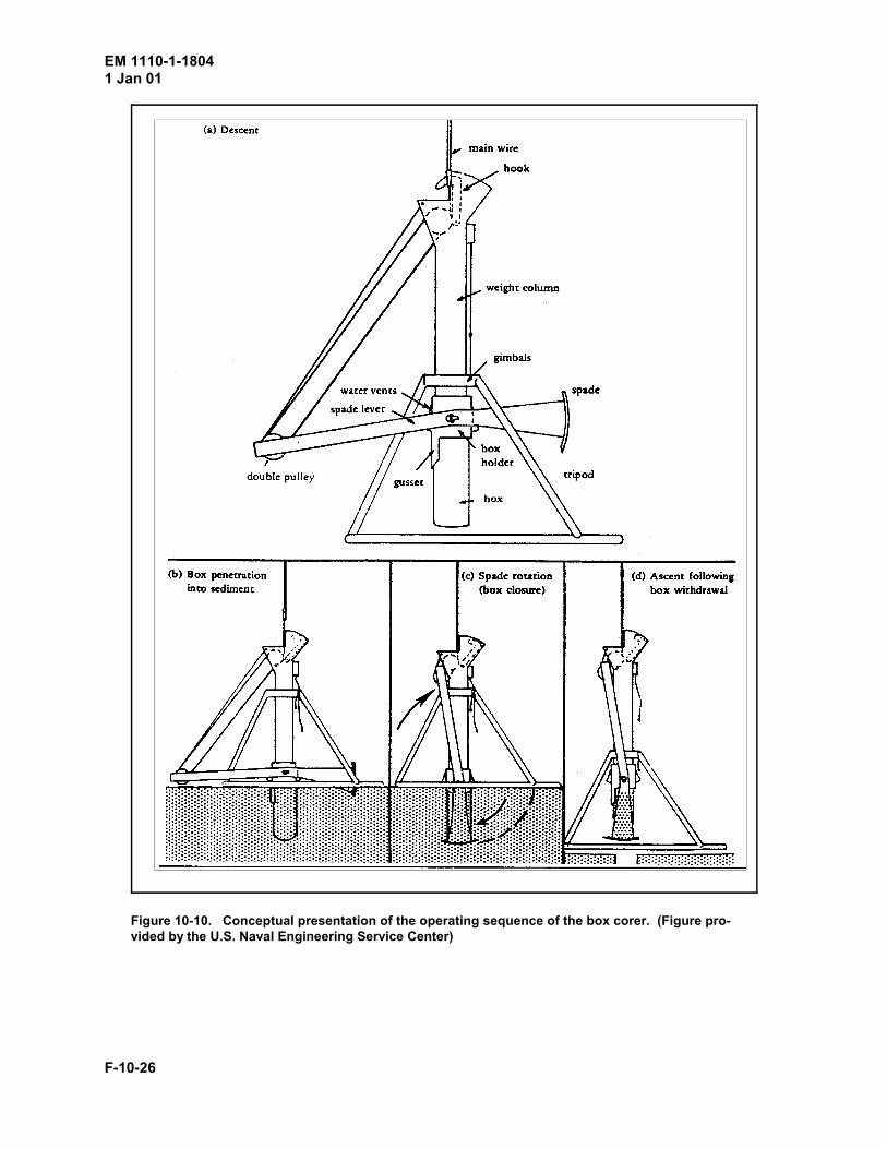
(2) Box corers. A box corer is a device that contains a box which takes a large, relativelyundisturbed sample when lowered to the seafloor by a wireline from the work platform. The box corer ispushed into the sediment by its own weight. When the deployment line is retracted, the bottom of thebox is closed off by a rotating spade before the box corer is lifted. Most box corers can be operated inany water depth.

EM 1110-1-18041 Jan 01
F-10-7
Box corers are available from several manufacturers, and therefore the design, size, and operation of eachmay vary slightly. The boxes are usually constructed of stainless steel or aluminum; sizes range from 10by 30 by 30 cm (4 by 12 by 12 in.) to 30 by 30 by 90 cm (12 by 12 by 36 in.) to as large as 50 by 50 by60 cm (20 by 20 by 24 in.). Most boxes have a bottom plate for supporting the sample in transport and aremovable side for access to the sample after it has been retrieved. The parts of the box corer and itsoperational sequence are presented conceptually in Figure 10-10.
The box corer should be prepared for use according to the manufacturer's instructions. Care should betaken to ensure that the safety pins which prevent pretripping are set correctly. After the sampler is liftedoff the deck, the pins supporting the weight column should be removed. Safe lowering rates for boxcorers depend on the seas and the type of device. For example, in calm seas, the box corer can belowered fairly rapidly but should be slowed considerably as it nears the bottom to allow the corer tostabilize; in rough seas, the box corer should be lowered at a moderate rate and should not be slowed asthe corer nears the bottom. When the box corer touches the bottom, deployment of the wireline shouldbe stopped immediately to prevent excess line from getting tangled and interfering with the operation ofthe corer. If desired, a bottom-sensing pinger can be attached to the wireline; to prevent damage to thepinger during retrieval of the sampler, the wire should be marked to alert the winch operator of thelocation of the pinger.
After the box has been driven into the sediment by its weight, the corer can be retrieved. As the wirelineis recoiled, the spade is rotated to close off the bottom of the box before the box is pulled out of theseafloor. The corer can be retrieved as fast as is possible but should be slowed as it nears the watersurface. Once the corer is out of the water, it should not be set on the deck until the weight columnsupport pins have been placed and a rope has been tied around the spade to prevent it from moving as thetension in the wireline is released.
To remove the sample box, a bottom plate must be inserted between the spade and the bottom of the boxand clamped before the spade is released and returned to its original position. If the box corer isequipped with an integral spade, the box assembly can be removed from the frame by simply looseningtwo bolts. After the box sample has been removed from the sampler, the sample can be extruded andsubsampled or stored in the box and sealed. Sampling logs for box cores should include informationsuch as the type of box corer, its size, the weight column, the size and/or weight of sample, subsamplestaken, and observations or remarks.
Box corers require a midsized vessel with deployment equipment that will provide the height clearancenecessary to deploy and retrieve the box. If an A-frame is used, both vertical and horizontal clearancesshould be checked. The amount of deck space required is typically small; usually a moderate workingarea plus space for the footprint of the corer is sufficient. Although it is not necessary for the vessel tostay in a fixed position during the sampling operation, position data should be recorded at the instant thecorer touches bottom. It should also be noted that core recovery is usually enhanced if the corer isbrought to the surface of the water in a nearly vertical retrieval pattern.
The principal advantage of a box corer is that a large, relatively undisturbed sample of cohesive materialcan be retrieved. The disadvantages of the box corer include the short length of sample which isretrieved and the difficulty of sampling cohesionless sediments which usually wash out of the box corerduring retrieval.
(3) Gravity corers. Although several types of gravity corers are available, all are operated similarly.In general, gravity corers consist of a large weight on top of a steel core barrel which contains a plastic

EM 1110-1-18041 Jan 01
F-10-8
liner. The corer is lowered and raised from the seafloor by a wireline, although during the actualsampling process, the corer is allowed to free-fall and penetrate the sediment. Gravity corers can be usedin almost any water depth; however, in shallow water, adequate free-fall distance must be available forthe sampler to deploy.
Gravity corers have been classified by size or by operational method. Historically, gravity corers weredivided into three groups based upon size: Phleger corers, Ewing corers, and deep-ocean corers. Today,several sizes of gravity corers are available; consequently, the operational method, which is based uponthe requirement that a valve or internal piston is used to enhance sample recovery, provides a betterclassification system. Typically, the smaller, shorter corers use a valve and are commonly referred to as�gravity� corers, whereas the larger, longer corers use a piston and are referred to as �piston� corers. Adiscussion of the gravity and piston corer is presented herein.
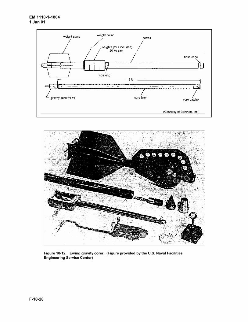
(a) Valve-type gravity corers. Gravity corers are manufactured by several companies and can bedesigned to meet almost any coring requirements. The two most common devices are the Phleger andEwing corers. The Phleger corer, which is shown in Figure 10-11, is typically 0.9 to 1.2 m (3 to 4 ft)long, weighs about 18 kg (40 lb), and can be used to obtain a sample 3.8 cm (1-1/2 in.) in diameter by 0.6m (2 ft) in length. The Ewing corer, which is illustrated in Figure 10-12, will vary in weight and lengthdepending upon the sample size; the weight of the sampler ranges from 90 to 450 kg (200 to 1,000 lb)and can be used to obtain a sample that is 6 cm (2-1/2 in.) in diameter by 1.8 to 3.0 m (6 to 10 ft) inlength. These devices are strikingly similar. The wireline is attached to the bail, which is located at thetop of each corer. Below the bail is the weight stand; depending upon the type of sampler, the weightsare either permanent or removable. The core barrel, which is lined with a plastic liner and core catcher,is located below the weight stand. A core cutter is attached to the bottom of the core barrel. A checkvalve, which is used to retain the sample, is located at the top of the weight stand.
Before the gravity corer is deployed, the device should be assembled and inspected according to themanufacturer's instructions. The check valve should be inspected to ensure that it is working properly.If a trip arm release as shown in Figure 10-13 is used, it should be inspected for proper operation and thepresence of the safety pin. When the gravity corer is deployed, it can be lowered in the water veryrapidly but should be stopped as soon as the trip arm is released or the corer hits bottom. As soon as thecore has been obtained, the corer should be slowly pulled free of the bottom and then returned to thesurface as rapidly as possible. If the corer is relatively short with sufficient deck space and liftingclearance available, the corer should be retained in a vertical orientation until the core has been removed.As soon as the core cutter has been disconnected from the core barrel, the core liner can be removed.However, if the check valve creates a tight seal at the top of the sample, it may be necessary to break thesuction before removing the core to prevent core disturbance. After the core liner has been removedfrom the corer, it should be capped, labeled, and stored as suggested in the section on core handling. Thefield logs should be updated in a timely manner.
Vessel requirements for deploying gravity corers will vary slightly, depending upon the specifics of thecorer. Generally, the lifting equipment should be capable of handling the weight and the height of thefull corer and the tripped cable, if a trip arm is used. The requirement for keeping the vessel at a fixedlocation is not critical unless it is necessary to sample a specified point; however, the vessel should notbe permitted to move so far away from the embedded corer that it is pulled up at an angle.
The advantages of gravity corers include the ease of handling and the simplicity of operation. Theprincipal disadvantage is the short sample length. The difficulty of obtaining a longer core is caused byselective sampling; as the gravity corer penetrates the formation, the sidewall friction between the

Lt = Vt % Lc % Fc & (lt & dt)
EM 1110-1-18041 Jan 01
F-10-9
sediment and the liner builds up and eventually causes a plug to form at the core cutter. In an attempt tosample deeper sediments with a gravity-type corer, a piston was added; the piston-type gravity corer isdiscussed in the following paragraph. It is appropriate to note herein that Hvorslev (1949) recommendedthe maximum length-to-diameter ratio for an undisturbed sample of cohesive soil should be of the orderof 10 to 20; for offshore investigations, the length-to-diameter ratios are frequently much larger.Perhaps, the excessive length-to- diameter ratios may cause increased sample disturbance.
(b) Piston-type gravity corers. A diagram of a typical piston corer is shown in Figure 10-14. Thepurpose of the piston is to remain at the top of the sediment and create a suction as the core barrel ispushed into the sediment; the effect of the suction is to enhance the recovery of the core and perhapsincrease the length of the sample drive. As with the gravity corer, the piston corer has either a permanentweight or an adjustable set of weights at the top. Most piston corers can be used to obtain a 6.3- to 6.7-cm- (2-1/2- to 2-5/8-in.-) diam core; the length of the core is usually 3 to 15 m (10 to 50 ft), dependingupon the type of sediment, although cores up to 40 m (130 ft) in length have been obtained. The lengthof the piston corer can be adjusted by adding 3-m (10-ft) lengths of core barrel and using longer plasticliners.
With the exception of a few steps for the operation of the piston, the operation of the piston-type gravitycorer is similar to the operation of valve-type gravity corer, as noted in Figure 10-13. After the pistoncorer has been assembled according to the manufacturer's instructions, three additional steps are requiredbefore the sampler is deployed: the trip wire length should be adjusted, the clearance of the liftingequipment should be checked, and the core barrel should be filled with water. The length of the trip wireshould be preset before the sampler is deployed to ensure that the piston is stopped and held at or slightlyabove the sediment surface as the core barrel penetrates the formation. The length of the trip wire can becalculated by Equation 10-1:
(10-1)
where
L = length of the trip wiret
V = vertical distance the trip or trigger arm must move to release the corert
L = overall length of the corerc
F = free-fall distance the corer travels before it impacts the seafloor sedimentc
l = overall length of the trip or trigger weightt
d = depth of penetration of the trigger weight into the seafloor sedimentt
After the sediment has been sampled, about 0.3 to 0.6 m (1 to 2 ft) of water should be separating the topof the sediment and the bottom of the piston. This separation assures that the top sediments have beensampled. If the distance between the sediment and the piston is too large, the free-fall loop is too short orthe length of the trip wire is too long; then the length of the wire(s) should be adjusted by an amountequal to the length of the excess distance between the piston and the core. If the mud marks on theoutside of the corer indicate a significantly greater penetration depth than the length of the core retrieved,
EM 1110-1-18041 Jan 01
F-10-10
the free-fall loop should be shortened an amount equal to the difference between the core length and thepenetration depth.
Typically, the length of the trip wire is 3 to 6 m (10 to 20 ft), depending upon the overall length of thecorer and the depth of penetration of the trigger weight into the seafloor sediment; the latter value isusually 0.6 to 1.2 m (2 to 4 ft). The required clearance of the lifting equipment on the work platform canbe estimated as the sum of the length of the trip wire plus the length of the core tube. Short-piston corers,e.g., 3-to 6-m (10- to 20-ft) core length, can be deployed from a small crane or an A-frame, although itmay be necessary to drag the sampler across the deck. For longer piston corers, it will be necessary todrag the device across the deck and upright in the water. After the sampler is suspended in the water andthe trip weight has been deployed, the core barrel should be filled with water to prevent hydrostaticpressure from pushing the piston up as the device is lowered in the water.
After the sampler has been retrieved, the core cutter must be removed, the cable attached to the pistonshould be disconnected, and the bottom end of the liner containing the core catcher should be cut off.After the bottom of the core has been sealed, the plastic core tube should be removed from the samplingdevice. When the liner is removed from the barrel, the piston stop should be detached from the liner andthe top of the sample tube should be sealed. The length of the core should be measured, the length oftube containing the core catcher should be noted, and the field logs should be updated. When coreslonger than 3 m (10 ft) are obtained, the core liner should be pulled out a short distance, cut off, andsealed and labeled as each segment is removed. Core barrel sections can also be removed as needed asthe liner is removed from the sampler. Although the sampler must be placed horizontally to remove thecore liner, the sections of core should be turned upright as soon as possible and the top of each segmentshould be marked.
Although high-quality samples of cohesive sediments can be obtained with the piston corer, twosampling problems may occur: flow-in and piston surge. Flow-in occurs when the corer has not fullypenetrated the sediment, usually when the piston is located somewhere in the middle of the core barrel.As the wireline is pulled upward to retrieve the corer, the piston is pulled to the piston stop before thesample tube is moved; this movement creates a suction in the core liner which tends to draw sedimentinto the core barrel. The flow-in sediment, which is very difficult to distinguish from the actual core, isdisturbed. Fortunately, this problem can be minimized by the use of a split piston. When the split pistonis utilized, an upward pull on the line causes the piston to separate; the main piston locks at the top of thesediment, and the secondary piston slides upward until it rests against the piston stop. Piston surgeoccurs when the piston is moved as the core barrel is penetrating the sediment. Ideally, the pistonremains motionless during the sampling operation. However, the wireline is stretched by the weight ofthe sampler as the device is deployed. When the corer is tripped, an elastic wave travels up and down thewire and causes movement of the piston. Movement of the piston is also caused by the motion of thevessel. Presently, there is no universally accepted method for solving the piston motion problem.
(4) Vibratory corers. Over the years, many bottom-resting samplers have been built and used toobtain seafloor samples. Most of these devices were one-of-a-kind tools that eventually fell into disuseand no longer exist. However, vibratory-type corers have remained popular and are used extensively.Although several vibratory corers are commercially available, only typical vibratory corers are discussedherein. See paragraphs 7-5 and 8-2 for additional information on vibratory samplers.
The vibratory corer consists of a vibratory head attached to the top of the core barrel. The corer issupported in a bottom-resting frame which helps to ensure that the core barrel enters the sedimentvertically as well as doubling as a reaction for advancing the sampling tube. The combination of weight
EM 1110-1-18041 Jan 01
F-10-11
and vibration is generally used to drive the core barrel into the sediment, although vibrations can becombined with impact driving for some types of devices to increase the penetration. The vibrator can beelectric, pneumatic, or hydraulic. The sizes of cores range from 76 to 152 mm (3 to 6 in.) in diameter by3 to 12 m (10 to 40 ft) in length.
The vibratory corer should be operated and deployed according to the manufacturer's instructions. Careis needed to ensure that the inside of the core barrel is washed thoroughly before a new core liner isinserted to prevent the liner from becoming wedged against the walls of the core barrel. After the linerhas been inserted, the threads should be cleaned before the collar is attached. Before the sampler islowered to the ocean floor, the length of wireline to deploy the sampler should be calculated. For certaindevices, deployment of the wireline is double the length of the core; this design feature must beconsidered when the length of the line and the sample drive are calculated. Once the corer has reachedfull penetration or refusal, the corer should be retrieved and placed on the work platform. When the linerhas been removed from the core barrel, the cores can be cut into sections and sealed or opened for avisual analysis, as required. If extremely long cores have been taken, it may be necessary to detach asection of the core barrel to facilitate the removal of the core liner. If a full core was not obtained, thewater on top of the sample should be drained by cutting the liner above the top of the sample before thesample is handled or sealed.
The vibratory corer can be operated in most coastal waters, and a sample can be obtained in most types ofsediment. The time required to obtain a core depends on the density of the sediment. However, the coreis disturbed to some degree; the degree of disturbance depends on the corer as well as the type ofsediment. An example of a disturbed vibratory core is shown in Figure 10-15; the thin horizontal layersof dark sediment are curved downward due to disturbance. When sampling is conducted in nearshoreareas, foreign objects, such as timbers or concrete, are sometimes encountered. These obstacles preventthe corer from obtaining a full core and sometimes damage the core barrel.
c. Drill string samplers. Drill-string samplers, as the name implies, operate through a drill string.Because these samplers are covered in detail in Chapters 5 through 8, this section presents only theunique aspects of their use for offshore investigations. Drill-string samplers require an onshore type ofdrill rig which is installed on a drill ship for use in deep water or placed on a temporary work platform.The work platform for the drill rig can vary from a small float or scaffolding to a large offshoreworkboat; the size of the platform is dependent upon the size of the drill rig and the support equipmentrequired. The problems of using drill strings deployed from a work platform or vessel include themovement of the drill string as the platform is tossed about by the seas and the need to maintain aconstant bit pressure appropriate for the soil type. To minimize these problems, power swivels, asillustrated in Figure 10-16, have been used.
(1) Vertical stabilization of the drill string. Three techniques to stabilize a drill string againstvertical movement are available: (a) a heave compensator can be used on the vessel; (b) the drill stringcan be clamped to the seafloor; or (c) the drill string can be anchored to the formation with an inflatablepacker. A schematic diagram of each method is presented in Figure 10-17. Heave compensators aredevices that damp out vessel motion relative to drill-string movement with an hydraulic ram; thesedevices can be attached to either the crown block or the traveling block. A crown-block heavecompensator can control approximately 1.5 to 6.0 m (5 to 20 ft) of heave, whereas a traveling-blockheave compensator can control approximately 1.8 to 3.6 m (6 to 12 ft) of heave. Very heavy,hydraulically operated clamps which rest on the seafloor add to the reaction force available to the drillstring and provide a means to reenter the borehole, if necessary. However, these devices are ratherdifficult to deploy, and the support equipment requires extra deck space. An inflatable packer,
EM 1110-1-18041 Jan 01
F-10-12
commonly known as a down-hole anchor, can be attached to the drill string just above the bit and inflatedagainst the borehole walls during the sampling process. The device is activated by a �latch-in� samplingtool and pressurized by drilling mud. When sampling is complete, withdrawal of the sampling toolcauses the packer to deflate.
(2) Operating without motion compensation. If a motion compensation system is not available, thesampling tools, which are illustrated in Figure 10-18, can be used. These tools include a wireline-percussion sampler, a latch-in push sampler, and an hydraulic-piston sampler. The wireline-percussionsampler consists of a sliding weight and a sampling head to which sample tubes can be attached. Toobtain a sample, the weight is raised with the wireline and then allowed to free-fall to drive the samplerinto the formation. However, the �hammering� effect causes sample disturbance; therefore, the numberof hammer blows is usually limited to approximately 30. The latch-in push sampler relies on a shortsampling time to obtain a good sample without motion compensation. When the sampler is lowered intothe borehole, a mechanism latches onto the drill string; the weight of the drill string is then used to pushthe tube to the bottom of the borehole. When the sampler is lifted, the latch mechanism releases and thesampler is retrieved on a wireline. Waves of too short a period will not allow sufficient time for thesampler to be recovered before it is again pushed into the formation by the weight of the drill string. Thehydraulic-piston sampler is a jacking unit to which a 0.9-m- (3-ft-) long thin-walled sample tube has beenattached. To obtain a sample, the jacking unit is lowered through the drill string until it latches onto thedrill bit. Hydraulic pressure of the drilling fluid is then used to push the sample tube into the formation.During the sampling process, the piston rests on the sediment surface. After the sample has beenobtained, the sampler is retrieved by a wireline.
10-6. Special Considerations for Underwater Sampling
When working in the marine environment, certain conditions require special attention. Because saltwaterand saltwater mists are extremely corrosive, one of the most important aspects of any offshoregeotechnical investigation is the cleaning and maintenance of the equipment. Other problems includesample recovery and storage and the difficulty of referencing the depth or elevation of bottom sediments.Selected topics are discussed in the following paragraphs.
a. Equipment cleanup. During offshore investigations, the sampling equipment as well as thevessel may require frequent washing to remove sediment, which can cause equipment to malfunction, andto prevent safety hazards on the deck. Saltwater obtained from a small water pump or from the saltwatertap on the vessel can be used for this purpose. However, at the end of the workday, the samplingequipment, including the wire ropes and any hand tools that were exposed to saltwater, should be hosedoff with fresh water to prevent corrosion. If equipment is left underwater, sacrificial anodes should beattached to the equipment to counteract corrosion; locator pingers should also be attached to allequipment before it is deployed.
b. Corrosion resistant materials. Although most offshore coring equipment is constructed ofcorrosion-resistant materials, such as 316 stainless steel, the equipment needs to be maintained to remainoperational and safe. If a new system is being designed for use in the marine environment, a metallurgistshould be consulted early in the planning phase to assist in the selection of materials.
c. Wire rope. One of the most critical pieces of equipment for underwater sampling is the wire ropeor wireline. Unfortunately, it corrodes easily when it has been exposed to saltwater and is thenconsidered unsafe to use. Although galvanized wire rope is somewhat more corrosion resistant, it, too,will corrode when exposed to saltwater for a period of time. Therefore, most vessel and crane operators

EM 1110-1-18041 Jan 01
F-10-13
are unwilling to dip crane hooks and wire ropes into the saltwater. Consequently, lifting straps,deployment wires, wire ropes, and other equipment required for the job must be supplied as an addedcost to the project. A wire-rope catalog will provide information on the bending radius of the rope andthe static working loads. A good rigger or rigging manual should be consulted for properly tieing orterminating wire ropes. A torque-balanced wire rope which resists spinning when the equipment islowering is also available.
d. Sample liners. Another consideration in offshore sampling is the type of plastic liner used in thesampler. The most commonly used liner is a clear plastic made of cellulose acetate butyrate (CAB).However, CAB is not very strong, can be easily damaged, and allows some moisture loss. Other plasticswhich have been used for core liners include rigid polycarbonate (Lexan) and polyvinyl chloride (PVC).As compared to CAB, Lexan is fairly strong, allows less moisture loss, and is more expensive; PVC isalso fairly strong and allows little moisture loss, although it is opaque and contains heavy metals thatcould adversely affect the results of a chemical analysis of the soil sample. Some plastics can be customextruded to meet the coring applications, whereas others can be obtained only in stock sizes. Forextruded materials, there may be a minimum order or a tooling charge.
e. Core catcher. The most common type of core catcher is the mechanical �finger� type. Thefinger-type core catcher is relatively inexpensive and can be reused extensively provided that it is caredfor. Although it works well in cohesive soils, cohesionless soils sometimes wash out as the core isbrought to the surface. For hard-to-retain sediments, two other types of core catchers are available. Theretainer, which is shown in Figure 10-19, uses a polythylene sleeve affixed to the outside of a finger-typecatcher; after the core has been obtained, the bag collapses to retain the sample. Figure 10-20 showsanother type of core catcher which has a sphincter closure to retain the core. When a trip lever on thecore barrel is released, a nylon sleeve which is located inside the core barrel is twisted to close thebottom of the core barrel.
f. Location of the bottom. Because underwater sediments progress from muddy water, to apea-soup consistency, to mud, and eventually to a sediment with significant strength, one of the mostdifficult problems dealing with underwater sampling is determining the location of the �bottom� or the�mudline.� When sampling is done, especially in support of dredging operations, determining where themudline starts is of great importance. A method of defining the location of the bottom should be selectedand specified very clearly. One method is to use a flat steel plate of a specific dimension and weight; thebottom is defined as the point at which the plate comes to rest and does not move after a defined periodof time. The plate should be attached to a specified lowering line for which the amount of stretch hasbeen defined. An alternative method is to define the �bottom� as determined by a certain apparatus, suchas a fathometer or a nuclear density gauge. Several U.S. Army Corps of Engineers Districts andLaboratories have experience with these devices.
g. Gas-charged sediments. Occasionally, gas-charged sediments, which are extremely difficult tosample without disturbance, are encountered offshore. Recently, samples of gas-charged sediments havebeen obtained with a sampler that retains the sample in a pressurized chamber. A drill-string wirelinesystem is used to deploy the sampler. However, samples obtained in pressurized chambers are of littlevalue unless the sample containers are opened and the samples are prepared for testing at conditionscomparable to the in situ pressures; to achieve these conditions, the laboratory testing program can beconducted inside an hyperbaric chamber.
h. Sampling logs. As compared to the boring logs maintained for onshore investigations (seeChapter 13), the sampling logs for offshore operations require additional data such as the type of vessel

EM 1110-1-18041 Jan 01
F-10-14
or platform; the navigation system and site coordinates; the time, depth of water, tides, and weatherconditions; and the size and type of sampler and sampling procedures, including lowering and retrievalrates and the pullout load. An example of a data sheet that can be modified to meet the specific needs ofan underwater sampling investigation is shown in Figure 10-21.
10-7. Sample Handling and Storage
In general, the methods for handling and/or storage of samples obtained during offshore drilling andsampling operations should follow the procedures used for onshore samples, which are described inChapter 13 of this manual. However, special considerations are required for certain aspects of offshoreinvestigations, including subsampling box core samples, handling long core samples, and the transportand storage of samples.
Because the size of the box core is fairly large and cannot be handled easily, subsamples of the box coreshould be obtained onboard the vessel prior to shipping the soil samples to the onshore laboratory. Tosubsample a box core, a piston, which can be attached to a rigid frame above the core, is placed on thetop of the sample and is used as a guide for the tube that is pushed into the box core. The diameter of thesubsampling tubes should be selected based upon the laboratory tests to be conducted on the subsamples.After all subsample tubes have been pushed into the box sample, the sediment around the tubes should beremoved and saved for tests such as grain-size analysis and Atterberg limits.
Long cores that are obtained in plastic liners should be cut into segments 0.5 to 1.5 m (2 to 5 ft) long,depending on the proposed testing program, shipboard storage, shipping containers, and the estimatedtime for storage of the segments. In general, the length of the core should be decreased as the time forstorage is increased to reduce settlement and leakage. As the liner is removed from the coring device, apermanent felt-tip marker should be used to mark the segments of the tube with a consistent labelingscheme, such as the bottom segment being labeled �1� or �a,� etc.; each segment should also be labeledwith an arrow pointing towards the top of the sample. After a segment has been labeled and the plasticliner has been cut, the segment should be measured and its condition noted; it should then be capped,taped with plastic tape, sealed with wax or plastic wrap and aluminum foil, and labeled. As a minimum,the label should contain the name of the project, the site number or name, the core number and segmentnumber, the length of the segment, the date the core was taken, the depth of water, the sampler type, andany observations or problems. This information can be written on the plastic tube with a permanentmarker, engraved into the plastic, or written on a card and inserted into a self-adhesive plastic bagattached to the core tube.
Samples should be stored and transported under conditions that minimize or prevent additionaldisturbance. Recall that core samples have already been disturbed by the change of stress andtemperature as a result of being sampled at the relatively cool sea floor and recovered on the warm, andpossibly even hot, deck. Cores should be stored vertically in a framework that prevents them from beingjostled, and if necessary can be wrapped in plastic bubble wrap to cushion them from shipboardvibrations. The storage room should be maintained at a temperature of 2 to 4 deg C (35 to 40 deg F) witha relative humidity of 100 percent to prevent the growth of marine organisms. The method of packingthe cores for shipment to the onshore laboratory should be preplanned to ensure that the shipping cratesare designed to minimize core disturbance and the cores are sectioned to a standard length. The top ofthe shipping crate (hence, the top of the cores) should always be labeled �THIS END UP.� Becausecalcareous samples are difficult to transport without causing severe disturbance, onboard testing of thesematerials is recommended, if possible.
EM 1110-1-18041 Jan 01
F-10-15
10-8. Summary
Although numerous types of equipment are available for sampling offshore formations, a well-plannedsampling operation can reduce the degree of difficulty and the expenses involved by ensuring that theproper equipment is available to obtain the required number of samples of satisfactory quality. Nearly allof the samplers discussed in this chapter can be used to sample cohesive materials. However,bottom-resting devices may sink under their own weight and therefore cannot be used for sampling softsediments. For cohesionless soils, vibratory corers and wireline samplers can be used, although samplesobtained with the vibratory corer are disturbed, whereas samples obtained with wireline samplers arefairly expensive. Specialized core retainers will help retain cohesionless soils in the sample tube. Rocksampling will likely require a drill-string sampler, although a few bottom-resting rock corers have beenbuilt for sampling the top of rock formations. Calcareous formations can be sampled by most of thedevices discussed in this chapter. However, the effect of sample disturbance is unknown because theengineering behavior of calcareous materials cannot be predicted by conventional soil mechanics theory.Additional information on offshore sampling is available in the references cited in the section entitled�Bibliography� in Appendix A.

EM 1110-1-1804
1 Jan 01
F-10-16
Figure 10-1. Photograph of a small drill rig on a scaffold. Note: Safety is a very important consideration for Corps of EngineerProjects. Safety items, including hardhats, gloves, safety shoes, protective clothing, life vests, and dust or vapor masks, should beworn, as appropriate, for the particular drilling and sampling operations. (Figure provided by the U.S. Naval Facilities EngineeringService Center)

EM 1110-1-18041 Jan 01
F-10-17
Figure 10-2. Photograph of a barge set up for nearshore work. Note the crane, A-frame, and winch forlifting and lowering drilling equipment. (Figure provided by the U.S. Naval Facilities Engineering ServiceCenter)
EM 1110-1-18041 Jan 01
F-10-18
Figure 10-3. Photograph of a jack-up barge that can be used to support an onshore drilling rig. (Figureprovided by the U.S. Naval Facilities Engineering Service Center)

EM 1110-1-18041 Jan 01
F-10-19
Figure 10-4. Photograph of a sampling device hung from a pair of davits along the side of a vessel. (Figureprovided by the U.S. Naval Facilities Engineering Service Center)

EM 1110-1-1804
1 Jan 01
F-10-20
Figure 10-5. Photograph of a sampler being deployed with a mobile crane mounted on a barge. Because of insufficient deck space, the head of thesampler was supported over water by the crane while the base of the sampler was placed on the deck as the core was removed. Note: Safety is avery important consideration for Corps of Engineers projects. Safety items, including hardhats, gloves, safety shoes, protective clothing, life vests,and dust or vapor masks, should be worn, as appropriate, for the particular drilling and sampling operations. (Figure provided by the U.S. NavalFacilities Engineering Service Center)

EM 1110-1-18041 Jan 01
F-10-21
Figure 10-6. Photograph of a Boomerang corer. (Figure provided by the U.S. Naval FacilitiesEngineering Service Center)

EM 1110-1-18041 Jan 01
F-10-22
Figure 10-7. The operating sequence of the Boomerang corer. (Figure provided by the U.S. Naval FacilitiesEngineering Service Center)

EM 1110-1-18041 Jan 01
F-10-23
a. Diver-operated corer with parts identified
b. Diver and partner operating corer underwater
c. Divers capping bottom of core after pulling it out ofthe seafloor
Figure 10-8. Photograph of a hand-held diver-operated sampler available to government agencies throughNAVFAC�s Ocean Construction Equipment inventory. Note: Safety is a very important consideration for Corps of

EM 1110-1-18041 Jan 01
F-10-24
Engineers projects. Safety items should be worn, as appropriate, for the particular drilling and sampling operations(Figure provided by the U.S. Naval Facilities Engineer Service Center)

EM 1110-1-18041 Jan 01
F-10-25
Figure 10-9. Schematic diagrams of several dredges and grab samplers that can be used to obtaindisturbed, surficial sediment samples of the seafloor from almost any depth of water. (Figureprovided by the U.S. Naval Facilities Engineering Service Center)
EM 1110-1-18041 Jan 01
F-10-26
Figure 10-10. Conceptual presentation of the operating sequence of the box corer. (Figure pro-vided by the U.S. Naval Engineering Service Center)

EM 1110-1-18041 Jan 01
F-10-27
Figure 10-11. Photograph of the Phleger gravity corer. (Figure provided by the U.S. NavalFacilities Engineering Service Center
EM 1110-1-18041 Jan 01
F-10-28
Figure 10-12. Ewing gravity corer. (Figure provided by the U.S. Naval FacilitiesEngineering Service Center)

EM 1110-1-18041 Jan 01
F-10-29
Figure 10-13. Schematic diagram of the trip arm release for operation of the checkvalve in a valve-type gravity corer. (Figure provided by the U.S. Naval FacilitiesEngineering Service Center)

EM 1110-1-18041 Jan 01
F-10-30
Figure 10-14. Schematic diagram of a typicalpiston-type gravity corer. (Figure provided by theU.S. Naval Facilities Engineer Service Center)

EM 1110-1-18041 Jan 01
F-10-31
Figure 10-15. Photograph of a disturbed vibratory core. Note that the thin horizontal layers of darksediment are curved downward due to sampling disturbance. (Figure provided by the U.S. Naval FacilitiesEngineering Service Center)

EM 1110-1-18041 Jan 01
F-10-32
Figure 10-16. Schematic diagram of a custom-designed derrick with a power swivel which is usedto minimize the movement of the drill string as the work platform or boat is tossed about by theseas. (Figure provided by the U.S. Naval Facilities Engineering Service Center)

EM 1110-1-1804
1 Jan 01
F-10-33
Figure 10-17. A schematic diagram of the three common techniques used to stabilize a drill string against vertical movement of the work platform. (Figure provided by the U.S. Naval Facilities Engineering Service Center)

EM 1110-1-18041 Jan 01
F-10-34
Figure 10-18. Wireline sampling tools which can be used if a motion compensa-tion system is not available. (Figure provided by the U.S. Naval Facilities Engi-neering Service Center)

EM 1110-1-18041 Jan 01
F-10-35
Figure 10-19. Photograph of a finger-type sample catcher with a polythylene sleevefor retaining hard to sample materials. After the sample has been obtained, the bagcollapses to help retain the material in the sampling tube. (Figure provided by theU.S. Naval Facilities Engineering Service Center)

EM 1110-1-18041 Jan 01
F-10-36
Figure 10-20. Isometric drawing of a core catcher with a sphincter closure toretain the core. (Figure provided by the U.S. Naval Facilities Engineering ServiceCenter)

EM 1110-1-18041 Jan 01
F-10-37
Figure 10-21. Data log form for an underwater sampling investigation. (Figure provided by the U.S. NavalFacilities Engineering Service Center)