UNCLASSIFIED IIIIIIIIIIII VANCE AIR FORCE BASE …expresses its sincere gratitude to Marilyn S....
137
AD-A145 50 INSTALLATION RESTORATION PROGRAM PHASE I RECORDS SEARCH I/ VANCE AIR FORCE BASE OKLAHOMA(U) ENVIRONMENTAL SCIENCE AND ENGINEERING INC DENVER CO JUL 84 F8637-83-G-0010 UNCLASSIFIED F/G 13/2 NL IIIIIIIIIIII IIIIIIIIIIIII. I.EIIIIIIIhhml .II.I...EIIIE .II..EEEEEIIIEE
Transcript of UNCLASSIFIED IIIIIIIIIIII VANCE AIR FORCE BASE …expresses its sincere gratitude to Marilyn S....
AD-A145 50 INSTALLATION RESTORATION PROGRAM PHASE I RECORDS SEARCH I/VANCE AIR FORCE BASE OKLAHOMA(U) ENVIRONMENTAL SCIENCEAND ENGINEERING INC DENVER CO JUL 84 F8637-83-G-0010
UNCLASSIFIED F/G 13/2 NLIIIIIIIIIIIIIIIIIIIIIIIII.I.EIIIIIIIhhml.II.I...EIIIE.II..EEEEEIIIEE

1.8
t11.ll' .4~
MICROCOPY RESOLUTION TEST CHARTNAT IONAL SRE ALI TANDAIRFD 4 A
0In
INSTALLATION RESTORATION PROGRAMif PHASE I: RECORDS SEARCH
VANCE AIR FORCE BASEOKLAHOMA
Prepared for:
UNITED STATES AIR FORCEHQ AFESC/DEVP
Tyndall AFB, Florida
and
HQ ATC/DEVRandolph AFB, Texas
Submitted by:
REYNOLDS, SMITH AND HILLS, INC.Jacksonville, Florida
ENVIRONMENTAL SCIENCE AND ENGINEERING, INC.Denver, Colorado
CL&
July 1984 t984
84 09 12 081
NOTICE
This report has been prepared for the U.S. Air Force by Environmental
Science and Engineering, Inc., for the purpose of aiding in the
implementation of the Air Force Installation Restoration Program. It is not
an endorsement of any product. The views expressed herein are those of
the contractor and do not necessarily reflect the official views of the
publishing agency, the U.S. Air Force, or the Department of Defense.
Copies of this report may be purchased from:
National Technical Information Service
5285 Port Royal Road
Springfield, Virginia 22161
Federal government agencies and their contractors registered with Defense
Technical Information Center should direct requests for copies of this report
to:
Defense Technical Information Center
Cameron Station
Alexandria, Virginia 22314
!/
(0%
It@O~

TABLE OF CONTENTS
Section Page
EXECUTIVE SUMMARY 1
1.0 INTRODUCTION 1-1
1.1 BACKGROUND 1-11.2 PURPOSE, AUTHORITY, AND SCOPE
OF THE ASSESSMENT 1-11.3 METHODOLOGY 1-3
2.0 INSTALLATION DESCRIPTION 2-1
2.1 LOCATION/SIZE 2-12.2 HISTORY 2-12.3 ORGANIZATION AND MISSION 2-72.4 MAJOR TENANTS 2-8
3.0 ENVIRONMENTAL SETTING 3-1
3.1 METEOROLOGY 3-1
3.2 GEOGRAPHY 3-1
3.2.1 PHYSIOGRAPHY 3-13.2.2 SURFACE HYDROLOGY 3-3
3.3 GEOLOGY 3-5
3.3.1 GEOLOGIC SETTING 3-53.3.2 SOILS 3-143.3.3 GEOHYDROLOGY 3-16
3.4 WATER QUALITY 3-19
3.4.1 SURFACE WATER 3-193.4.2 GROUND WATER 3-23
3.5 BIOTA 3-24
4.0 FINDINGS 4-1
4.1 ACTIVITY REVIEW 4-1
4.1.1 INDUSTRIAL OPERATIONS 4-14.1.2 FUELS/OILS HANDLING AND STORAGE 4-24.1.3 PESTICIDE/HERBICIDE HANDLING
STORAGE 4-4
4.1.4 PCB HANDLING AND STORAGE 4-4

TABLE OF CONTENTS(Continued)
Section Page
4.2 HAZARDOUS WASTE GENERATION/DISPOSAL 4-5
4.2.1 GENERATING OPERATIONS 4-54.2.2 DISPOSAL METHODS 4-104.2.3 SPILLS OR INCIDENTAL DISCHARGES 4-114.2.4 OFF-BASE DISPOSAL SITES 4-11
4.3 AREAS OF POTENTIAL CONTAMINATION 4-12
4.4 HAZARD ASSESSMENT 4-17
5.0 CONCLUSIONS 5-1
6.0 RECOMMENDATIONS 6-1
6.1 PHASE II MONITORING RECOMMENDATIONS 6-16.2 EXISTING FACILITIES/PROCEDURES 6-66.3 LAND USE GUIDELINES 6-6
BIBLIOGRAPHY
APPENDICES
A - GLOSSARY OF TERMINOLOGY, ABBREVIATIONS,AND ACRONYMS
B - TEAM MEMBER BIOGRAPHICAL DATAC - LIST OF INTERVIEWEES AND OUTSIDE CONTACTSD - MASTER LIST OF SHOPS AND LABSE - PHOTOGRAPHS OF DISPOSAL/SPILL SITESF - USAF IRP HAZARD ASSESSMENT RATING METHODOLOGYG - HAZARD ASSESSMENT RATING METHODOLOGY FORMS
ii

LIST OF TABLES
Table
1 Summary of HARM Scores 6
3.1-1 VAFB Climatic Summary 3-2
3.3-1 Generalized List of Stratigraphic Unitsof North-Central Oklahoma 3-10
3.4-1 Water Quality Data for Surface Watersand Discharges for VAFB 3-22
4.1-1 POL Storage Tanks 4-3
4.2-1 Waste Generation and Disposal 4-6
4.4-1 Summary of HARM Scores 4-18
6.1-1 Summary of Recommended Monitoring for VAFBPhase [[ Investigations. 6-5
iii
LIST OF FIGURES
Figure Page
1 Areas of Potential Contamination 5
1.3-1 Decision Process 1-4
2.1-1 Location Map 2-2
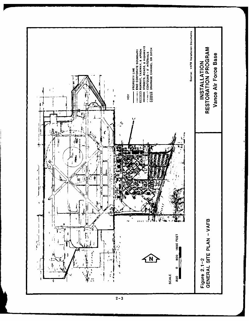
2.1-2 General Site Plan - VAFB 2-3
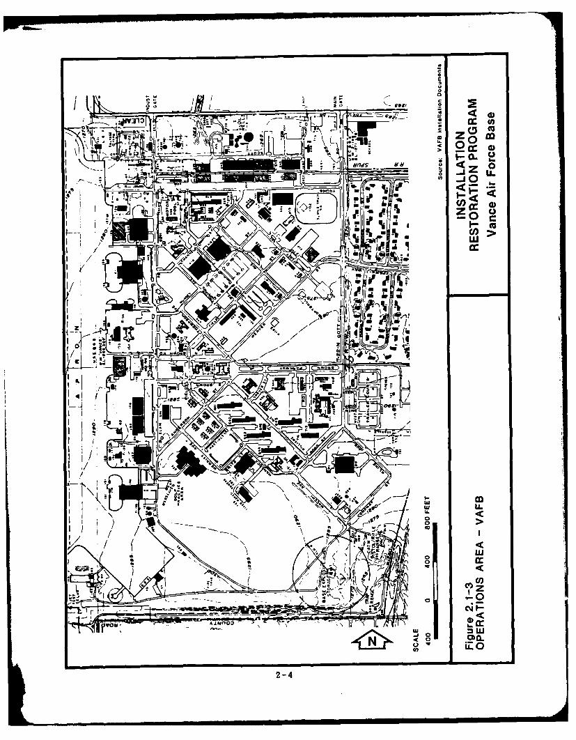
2.1-3 Operations Area - VAFB 2-4
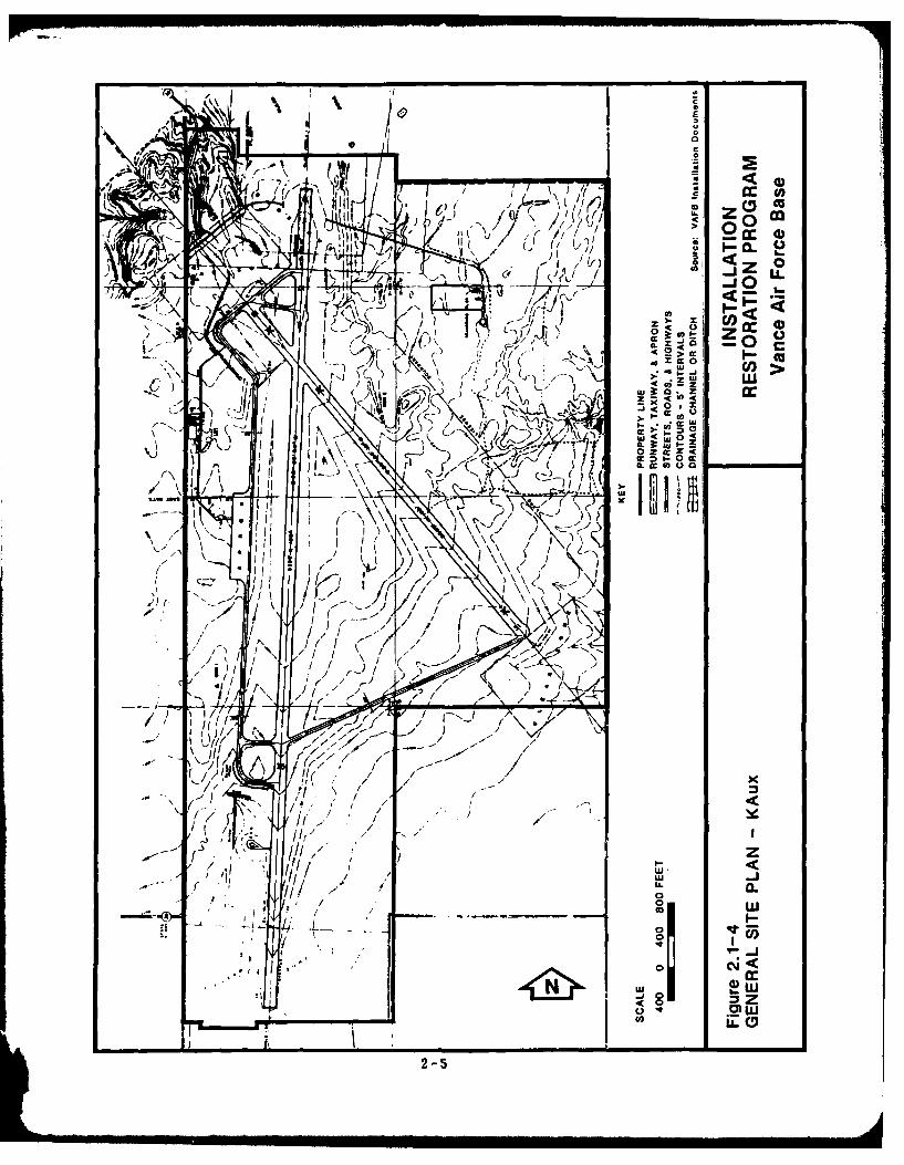
2.1-4 General Site Plan - KAux 2-5
3.2-1 Drainage Patterns 3-4
3.2-2 Drainage Patterns - KAux 3-6
3.3-1 Stratigraphic Cross Section ThroughNorth-Central Oklahoma 3-12
3.3-2 Geologic Map of North-Central Oklahoma 3-13
3.3-3 Soil Types 3-15
3.3-4 Principal Aquifers of North-Central Oklahoma 3-18
3.3-5 Soil Boring Locations 3-20
4.3-1 Areas of Potential Contamination 4-13
4.3-2 Areas of Potential ContaminationSouth and East Boundaries 4-14
4.3-3 Areas of Potential ContaminationWest Gate Area 4-15
iv

ACKNOWLEDGEM ENTS
The Phase I Records Search of Vance Air Force Base could not have been
accomplished without the support and cooperation of numerous U.S. Air
Force and civilian personnel. In particular, the Records Search Team
expresses its sincere gratitude to Marilyn S. Wells and John E. Merz of
Northrop Worldwide Aircraft Services Civil Engineering Department and to
Colonel James A. Nugent of the 71st Air Base Group and his staff.
V
EXECUTIVE SUMMARY
The Department of Defense (DOD) has developed a program to identify and
evaluate past hazardous material disposal sites on DOD property, control the
migration of hazardous contaminants, and control hazards to health or
welfare that may result from these past disposal operations. This program
is called the Installation Restoration Program (IRP). The IRP has four
phases consisting of Phase I, Initial Assessment/Records Search; Phase [I,
Confirmation and Quantification; Phase III, Technology Base
Development/Evaluation of Remedial Action Alternatives; and Phase IV,
Operations/Remedial Actions. The IRP will be the basis for response
actions on Air Force installations under the provisions of the Comprehensive
Environmental Response, Compensation, and Liability Act (CERCLA) of 1980,
Executive Order 12316, and 40 CFR 300 Subpart F (National Oil and
Hazardous Substances Contingency Plan). CERCLA is the primary legislation
governing remedial action at past hazardous waste disposal sites.
Environmental Science and Engineering, Inc. was retained by the United
States Air Force to conduct the Phase I, Initial Assessment/Records Search
for Vance Air Force Base (VAFB) and its subinstaliation, Kegelman Auxiliary
Field (KAux) under Contract No. F08637-83-G0010-5000.
INSTALLATION DESCRIPTION
VAFB is located in north-central Oklahoma, approximately 5 miles south of
downtown Enid, which is the seat of Garfield County . The family housing
area of VAFB lies within the Enid city limits. KAux is located
approximately 30 miles north-northwest of VAFB in Alfalfa County,
Oklahoma, just east of the Great Salt Plains Reservoir.
VAFB is the home of the 71st Flying Training Wing which has the mission
of conducting undergraduate pilot training. The 11-month undergraduate
pilot training program consists of 175 hours of flying, 367 hours of academic
training, and 134 hours of officer training, the accumulation of which
qualifies the student the as an Air Force pilot.
The basic mission of VAFB has remained essentially the same since the base
was first activated. However, over that period the type of aircraft being
1
flown has changed several times. Between 1942 and 1956, propeller-driven
aircraft were used. These were followed by the T-33 between 1956 and
1960. The T-37 was introduced in 1960 and was joined by the T-38 in
1964.
ENVIRONMENTAL SETTING
The environmental setting data reviewed for this investigation indicate the
following major points that are relevant to the evaluation of past hazardous
waste management practices at VAFB and KAux:
o Mean annual precipitation is 27.9 inches with a lake evaporation
rate of approximately 60 inches per year. Wind direction is
variable with a predominance from the south.
o Both VAFB and KAux lie within the Arkansas River Basin. VAFB
is located on a topographic high, and there is no on-flow of
surface water from adjacent areas. In general, the north and
central sections of the base drain to Boggy Creek. The southern
portions of the base drain into Hackberry Creek. KAux lies
immediately south of the Salt Fork of the Arkansas River, draining
directly to the river through a number of small channels.
o The soils at VAFB and KAux are generally fine sandy loams that
are well-drained. These soils tend to be underlained at a depth of
2-4 feet with clay layers. These layers are generally dis-
continuous and do not constitute an aquiclude.
o VAFB and KAux are underlain by minor local aquifers. Ground
water occurs in strata that are predominantly shale with some
siltstone and fine-grained sandstone. Recharge is from local
precipitation, and well yields are small.
o Ground water in the vicinity of VAFB and KAux is characterized
by variable quality, with sulfate, chloride, nitrate, dissolved solids,
and hardness often in concentrations exceeding recommended upper
limits for drinking water. These conditions are not thought to be
related to activities at VAFB or KAux.
o No threatened or endangered species regularly inhabit either VAFB
or KAux.
2

METHODOLOGY
The objective of Phase I was to identify the potential for environmental
coj. amination from past waste disposal practices at VAFB and to assess the
potential for contaminant migration. Activities performed in the Phase I
study included review of site records; interviews with personnel familiar
with past goneration and disposal activities; determination of estimated
quantities and locations of curent and past hazardous waste treatment,
storage, and disposal; performance of field and aerial inspections; and
development of conclusions and recommendations.
FINDINGS AND CONCLUSIONS
All the major industrial operations at VAFB relate to the maintenance and
operation of the aircraft used in pilot training. The different levels of
maintenance and the various operations are conducted by several different
organizations at a number of locations on the base. Operations include
engine repairs/overhauls; electrical, hydraulic, and fuel system repairs;
painting; metal plating/finishing; support equipment maintenance, fuel supply
and handling, and maintenance of base facilities. No industrial activities are
conducted at KAux and there is no underground fuel storage.
The materials, construction, and maintenance requirements of the earlier
aircraft differed from those currently in use. Thus, the specific equipment
and materials used in current maintenance operations may not reflect the
years prior to 1960, although the categories of maintenance being performed
and the locations where they are conducted have changed little.
The main types of waste generated at VAFB are fuel, oils and solvents,
paints and paint strippers, and metal plating/treatment solutions. Waste
fuel, oil, and solvents include JP4, engine oil, PD680, and acetone, which
are derived primarily from periodic maintenance and engine repair
operations. Waste consisting of paint residue, strippers, and thinner is
generated by the parts, aircraft, and vehicle painting operations. Metal
plating/treatment waste is generated at the jet engine shop and metal
plating shops and consists of phosphoric acid, chromic acid, potassium
permanganate, cadmium, and descaling solutions. The general trend in waste
disposal over the years since VAFB first began operation has been from
3
largely unsegregated disposal in base landfills toward extensive wastesegregation and contract disposal.
'This study identified eight areas on VAFB subject to contamination byindustrial and/or hazardous waste as a result of handling and disposal
practices (Figure 1). Of these eight areas of potential contamination, sixwere determined to require rating with the Hazard Assessment Rating
Methodology (HARM) system. The Bldg. 110 Area Storage Tank and the
Hazardous Waste Accumulation Point were not rated due to the lack of
potential for contamination and migration. No evidence was found ofleakage or spills at either of these two sites. The HARM scores for the six
remaining sites are summarized in Table 1.
Tank Farm Landfill
This site was operated as a general purpose trench and fill landfill prior to
1952. Operating personnel reported the contents were mostly householdsolid wastes, but included containerized liquids. Some lead gasoline tank
sludge was buried under the existing berm around Tank 267. The potential
exists for contamination and migration from metals, solvents, fuels, and oils.
East Boundary Landfill
Operated as a general purpose trench type landfill from approximately 1952to 1957, this area is currently cultivated as garden plots by base personnel.
Materials deposited here were mostly general solid waste and some industrial
liquids. Potential exists for contamination by and/or migration of metals,
solvents, fuels, and oils.
Southeast LandfillTrench and fill disposal of solid waste proceeded through this area from
1958 to 1965. Disposal of industrial wastes in this area is thought to belimited. Some potential exists for contamination by metals and solvents.
Chemical Disposal PitsThis open area adjacent to the south boundary drainage ditch was used to
dig a series of liquid waste disposal pits from approximately 1960 to 1970.
4

oc0 u0
0 Q
It N 6'/7dS 0
I'~~~ 4r1 ~-' /
z c20..
ZIL(z
LL. 0IL j Z L
Y. La )
z 5

Table 1 - Summary of HARM Scores
Waste WasteReceptors Characteristics Pathways Management Total
Rank Site Subscore Score Subscore Factor Score
1 Chemical 61 100 52 1.0 71Disposal Pits
2 Firefighter 61 64 44 1.0 56Training Area
3 Tank Farm 64 56 44 1.0 55Landfill
4 East Boundary 61 30 52 1.0 48Landfill
5 Tank Sludge 61 37 44 1.0 47Disposal Area
6 Southeast 61 10 52 1.0 41Landfill
Source: ESE, 1984.
6
Soils are relatively impermeable, but potential contamination or migration
exists, primarily for metals since materials disposed of were mostly plating
solutions and sludges.
Tank Sludge Disposal Area
Used as a one-time disposal area for sludge from fuel tanks, this site is
between the drainage ditch and south base boundary. Potential exists for
metals contamination and migration.
Firefighter Training Area
Fuels, oils, and solvents were reportedly dumped in a shallow ground
depression at this location until approximately 1970. A new Firefighter
Training Area is located on the site.
RECOMMENDATIONS
Recommendations for Phase II monitoring include installation of 11
monitoring wells to be sampled and analyzed for a variety of contaminants.
Water level measurements and geophysical logging of boreholes are included
as part of the program. Surface water and sediment analyses are
recommended on ditches draining the known disposal areas to provide data
on this potential migration pathway. Soil analyses are included in the
Firefighter Training Area, where contamination of near surface soils may
exist, and at the East Boundary Landfill, where food crops are being grown
in the cover material of the old landfill.
7
1.0 INTRODUCTION
1.1 BACKGROUND
Due to its primary mission, the U.S. Air Force (USAF) has long been engaged
in operations dealing with toxic and hazardous materials. Federal, state,
and local governments have developed strict regulations to require that
disposers identify the locations and contents of disposal site and take action
to eliminate the hazards in an environmentally responsible manner. The
primary Federal legislation governing disposal of hazardous waste is the
Resource Conservation and Recovery Act (RCRA) of 1976, as amended.
Under See. 6003 of the Act, Federal Agencies are directed to assist the
U.S. Environmental Protection (EPA) and under Sec. 3012, state agencies are
required to inventory past disposal sites and make the information available
to the requesting agencies. To assure compliance with these hazardous
waste regulations, the Department of Defense (DOD) developed the
Installation Restoration Program ([RP). The current DOD IRP policy is
contained in Defense Environmental Quality Program Policy Memorandum
(DEQPPM) 81-5, dated Dec. 11, 1981, and implemented by USAF message,
dated Jan. 21, 1982. DEQPPM 81-5 reissued and amplified all previous
directives and memoranda on the IRP. DOD policy is to identify and fully
evaluate suspected problems associated with past hazardous contamination
and to control hazards to health and welfare that resulted from these past
operations. The IRP will be the basis for response action on USAF
installations under the provisions of the Comprehensive Environmental
Response, Compensation, and Liability Act (CERCLA) of 1980, as clarifiedby Executive Order 12316, and 40 CFR 300 Subpart F (National Oil and
Hazardous Substances Contingency Plan). CERCLA is the primary legislation
governing remedial action at past hazardous waste disposal sites.
1.2 PURPOSE, AUTHORITY, AND SCOPE OF THE ASSESSMENT
The IRP has been developed as a four-phase program, as follows:
Phase I - Initial Assessment/Records Search
Phase H - Confirmation and Quantification
Phase III - Technology Base Development
Phase IV - Operations/Remedial Actions
1-1
Environmental Science and Engineering, Inc. (ESE) conducted the records
search at Vance Air Force Base (VAFB) and its subinstallation, Kegelman
Auxiliary Field (KAux), with funds provided by the Air Force Training
Command (ATC). This report contains a summary and evaluation of the
information collected during Phase I of the IRP and recommendations for
any necessary Phase 11 action.
The objective of Phase I was to identify the potential for environmental
contamination from past waste disposal practices at VAFB and to assess the
potential for contaminant migration. Activities performed in the Phase I
study included the following:
1. Review of site records;
2. Interviews with personnel familiar with past generation and
disposal activities;
3. Inventory of wastes;
4. Determination of estimated quantities and locations of current and
past hazardous waste treatment, storage, and disposal;
5. Definition of the environmental setting at the base;
6. Review of past disposal practices and methods;
7. Performance of field and aerial inspections;
8. Gathering of pertinent information from federal, state, and local
agencies.
9. Assessment of potential for contaminant migration; and
10. Development of conclusions and recommendations for follow-on
action.
ESE performed the onsite portion of the records search during March 1984.
The following team of professionals was involved:
o Bruce N. McMaster, Ph.D., Senior Chemist and Project Manager,
16 years of professional experience.
o Jackson B. Sosebee, Jr., Chemist/Geologist and Team Leader,
12 years of professional experience.
o William G. Fraser, P.E., Environmental Engineer, 9 years of
professional experience.
o Keith C. Govro, Ecologist, 9 years of professional experience.
1-2

Detailed information on these individuals is presented in Appendix B
1.3 METHODOLOGY
The methodology utilized in the VAFB records search began with a review
of past and current industrial operations conducted at the base. Information
was obtained from available records, such as shop files and real property
files, as well as interviews with past and current base employees from the
various operating areas. Interviewees included current and past Air Force
personnel and those associated with Northrop Worldwide Aircraft Services,
Inc. or previous base operations contractors, Bioenvironmental Engineering
Services (BES), and tenant organizations on the base. A list of interviewees
by position and approximate years of service is presented in Appendix C.
The next step in the activity review was to determine the past management
practices regarding the use, storage, treatment, and disposal of hazardous
materials from the various operations on the base. Included in this part of
the activities review was the identification of all known past disposal sites
and other possible sources of contamination, such as spill areas.
A ground tour and helicopter overflight of the identified sites were then
made by the ESE Project Team to gather site-specific information including:
(1) visual evidence of environmental stress; (2) the presence of nearby
drainage ditches or surface water bodies; and (3) visual inspection of these
water bodies for any obvious signs of contamination or leachate migration.
Using the process shown in Fig. 1.3-1, a decision was then made, based on
all of the above information, regarding the potential for hazardous material
contamination at any of the identified sites. If no potential existed, the
site was deleted from further consideration. If potential for contamination
was identified, the potential for migration of the contaminant was assessed
based on site-specific conditions. If there were no further environmental
concerns, the site was deleted. If the potential for contaminant migration
was considered significant, the site was evaluated and prioritized using the
Hazard Assessment Rating Methodology (HARM). A discussion of the HARM
system is present in Appendix H. The sites, which were evaluated using the
HARM procedures, were also reviewed with regard to future land use
restrictions.
1-3

INSTALLATION RESTORATION PROGRAMPHASE I--RECORDS SEARCH
DECISION PROCESS
Complete List of Sites
Evaluation of Past Operation
at Listed Sites
No Potential forYeContamination
Delete SitesPtnia o
E vironment alocrs N
E Program
f ConsolidateI Site-Specific
Data
Hazard Assessment
Rating Methodology
f Nwe rica IF Si te Rating
Recommendations98
Figure 1.3-1 INSTALLATIONDECISION PROCESS RESTORATION PROGRAM
Vance Air Force Base
1-4
2.0 INSTALLATION DESCRIPTION
2.1 LOCATION/SIZE
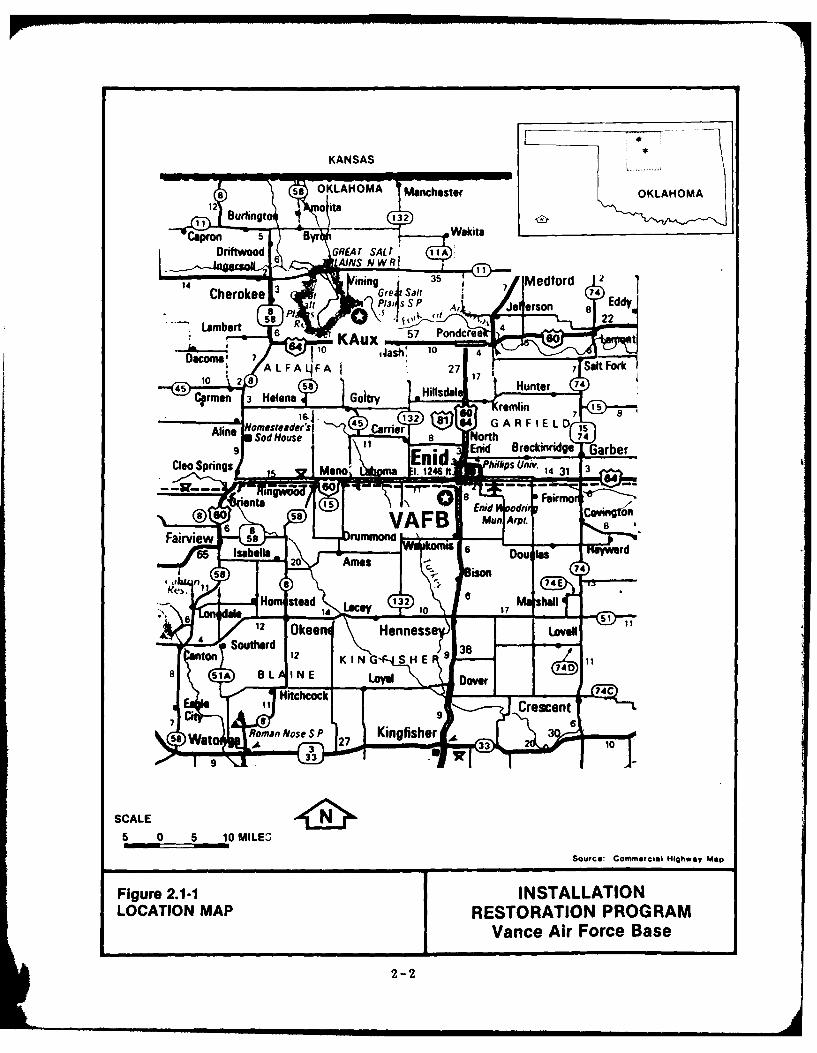
VAFB is located in north-central Oklahoma, approximately 5 miles south of
downtown Enid, which is the seat of Garfield County (Fig. 2.1-1). The
family housing area of VAFB lies within the Enid city limits. KAux is
located approximately 30 miles north-northwest of VAFB in Alfalfa County,
Oklahoma, just east of the Great Salt Plains Reservoir.
The runways and taxiways at VAFB cover 1,100 of the 1,847 acres which
make up the base. The remaining area comprises maintenance shops,
operations, housing, and recreation areas (Figs. 2.1-2 and 2.1-3). Outgrants
associated with VAFB include leases of 0.021 acres to the telephone
company, 0.148 acres to the credit union, 0.02 acres to the bank, and 1
acre to Cotton Petroleum Co. VAFB leases 60.345 acres from private
parties for military family housing.
KAux covers a total of 1,066 acres, of which 365 acres are airfield and
operations areas (Fig. 2.1-4). The remainder is largely unimproved (VAFB,
1976). Approximately 7 acres of KAux is leased to private parties for
grazing. KAux obtains water from three wells which are located on 4 acres
of land leased from other parties. A small pond (0.5 acres) is currently
being developed on KAux for public fishing.
2.2 HISTORY
The installation was initially authorized under the Fourth Supplemental
National Defense Appropriation Act of 1941, Mar. 7, 1941. Construction
was begun in July 1941, and the first buildings were occupied in November
of that year. The land on which the base was constructed was primarily
cattle range in the years before 1893, when a land rush resulted in its
conversion to wheat production. By 1941, when the land was transferred to
the federal government, Enid was a principal grain storage terminal and
flour milling center and was fast becoming an important petroleum
production and refining center.
The base was officially named Enid Army Flying School on Feb. 11, 1942.
It was used for basic pilot training in the T-13a and T-15 aircraft through
2-1
KANSAS : L
e 58 OKLAHOMAA Manchester OKLAHOMA12 Burlingt
to 132ir i --7 WakitaCapron
Byr 1- 9 ,0 GRIEA r SAL T 11A
6 JAINS N W R Iining 35
14 7/lMedtordCherokee Gret Salt 74
P131 S S P A t /io4orson lldy
1,58 22
Lambert Rt 46 57 Pondcree
84 I(Aux nt
Docomal 7 .4aih 10 4
ALFA4FA 27 17 7 Salt Fork
45 10 2 Hillsdal Hunter 74
Cirmen 3 Helena Goitry " - fromlin 15
Aline Homesteeder's 45 Carrier 81 64 GAR F IE L D isSod House 1 8 North 74
9 Enid BrockinridgO Garber
Cleo Springs nid hiffifis Uh'V Mono'k\L na El. 1246 14 31 3
n -- iii 11.111r -Wz- -- - --
on 5 7 T 8 bn nd o Feirmov,7@ so 0-
6 a VAFB Mun Arpt. 0
Fairview 59 rummond 6 R" rd65 Isabelle 20 Ames Dou Ws-C.
ison
a
74E T
Ho ead 132 6 M4 hallI& Lacey 10
4 12 Okee Henne se LovellSouthard
12 38nton KING, SHE
51A OL INE Loval Dover
Hitchcock 74C
Crescent9
6
a Wato Roman Alose S P 27 Kingfisher A 3A 3 33 10
'01 9 33 -7 v
SCALE
5 0 6 10 MILE0
SQUFCG: CommW621 Highway Moo
Figure 2.1-1 INSTALLATION
LOCATION MAP RESTORATION PROGRAM
Vance Air Force Base
2-2
c
E
0a
CC
lz W, Z 0 0
0 0 - z
2 <
s _j03I L
, 3: 0o
02-3C
0 C
4 C
0I
C,>
400
I ILL
1-0C4P:
2-4
CL
z0
0 (D
-ICl >J)1.
9L ,uj I-
0-
I *,,l.-
)LIV0H ) - o
N r~ ~ ,-'/ ~~IJ \ K '
_______if
6 g **-'~:~ IU~l ~ 4III, 2'
2-5-

much of World War I. In 1944, advanced students began training in the B-
25 and B-26. With the conclusion of the war and the reduced need for
pilots, the base was closed on Jan. 31, 1947.
Following the creation of the USAF as a separate service in 1947, the base
was reactivated under the name Enid Air Force Base on Jan. 13, 1948. The
mission at that time was to provide advanced pilot training in the T-6 and
B-25 aircraft. On July 9, 1949, the base was renamed VAFB.
By 1952, when the VAFB mission was changed from advanced to basic pilot
training, the T-6 aircraft had been replaced by the T-28. As advances in
aviation continued over the next decade, several more changes in aircraft
took place. In 1956, the T-33 single engine trainer replaced the B-25. In
1960, the twin-engine T-37 replaced the T-28, and by 1964, the T-33 had
been replaced by the supersonic T-38.
A major expansion of the runway systems was required to support the new
aircraft, which operated at much greater speeds. During 1955 and 1956, the
existing north-south runways were extended, and a third north-south runway
was constructed. This included an expansion of the base boundaries, and
extensive alterations to the taxiway, drainage, lighting, and traffic control
systems.
In 1960, VAFB was selected by the Air Force as part of an extended
experiment in contract services under which a civilian contractor provides
the support facilities normally provided by base agencies. This includes
aircraft and base maintenance, ground transportation, fire protection,
procurement, supply, and other services. The base has continued to operate
under this system, providing basic pilot training in the T-37 and T-38
aircraft. The initial contractor, Serve-Air, Inc., operated the base until
1972, when the contract was taken over by Northrop Worldwide Aircraft
Services.
KAux originally consisted of 960 acres on which airfield pavements and
facilities were constructed during World War 11 (1942 to 1943). An
2-6
additional 10 acres were purchased in 1943. It was activated in
January 1944 as Great Salt Plains Auxiliary Field Operational Training Unit.
After the war it was inactivated. In August 1948 it was reactivated. The
field was renamed Kegelman Auxiliary Field after Colonel Charles C.
Kegelman from El Reno, Oklahoma, in July 1949. In 1960, 15 acres were
purchased, and in 1965, an additional 81 acres were purchased, which
totaled 1066 acres for the present site.
2.3 ORGANIZATION AND MISSION
VAFB is the home of the 71st Flying Training Wing (FTW) which has the
mission of conducting undergraduate pilot training. The 11-month
undergraduate pilot training program consists of 175 hours of flying, 367
hours of academic training, and 134 hours of officer training, the
accumulation of which qualifies the student as an Air Force pilot.
In the first phase of training the students start their academic instruction.
This consists primarily of flight physiology and aircraft systems training.
Jet flying starts during the fourth week of training. In the second phase,
the students fly the Cessna T-37, a small twin engine jet trainer with a top
speed of 350 miles per hour (mph) and a ceiling of 25,000 feet. Each
student receives 32 hours of instrument flight simulator training during the
T-37 phase. The five-month third phase of training is given in the Northrop
T-38 Talon jet trainer. It is a supersonic plane with a top speed of 800
mph and a ceiling of 39,000 feet. The academic and flying training in the
third phase includes 34 hours in the T-38 instrument flight simulator.
VAFB trains approximately 400 pilots per year. The working population at
the base is approximately 2,600. Air Force personnel and dependents living
on base total approximately 850.
The 71st Air Base Group has the two-fold mission of providing limited
administrative services and support to the mission and base and providing
contract surveillance to assure Northrop Worldwide Aircraft Services is
providing those operations and services for which the civilian contractor is
responsible. The main contract services are aircraft maintenance, facilities
2-7
maintenance, civil engineering, flight simulation, open mess, personnel
services, and management services.
2.4 MAJOR TENANTS
The 2110 Communications Squadron (AFCS) directly supports the 71st FTW
by providing operations and maintenance of all air traffic control facilities
and systems located at VAFB. Additionally, the 2110 AFCS maintains the
UHF radios and meteorological equipment installed at VAFB and KAux.
Detachment 15, 24th Weather Squadron, provides weather support to the 71st
FTW to fulfill its mission. Additionally, Detachment 15 provides weather
support to transient aircrews and other base agencies.
The Defense Investigative Service (DIS) conducts personal security
background investigations on military, DOD civilians, and Defense Contractor
personnel whose duties require access to classified defense information.
2-8

3.0 ENVIRONMENTAL SETTING
3.1 METEOROLOGY
The VAFB region is classified as moist sub-humid as precipitation exceeds
that required for normal plant growth. At the base, instrument flight rule
(IFR) conditions prevail only 8 percent of the time. These conditions occur
more frequently in the winter and only infrequently in the summer.
Temperature and precipitation data for the base are summarized in
Table 3.1-1. Average daily maximum and minimum temperatures range from
44 0 F and 25 0 F in January to 93 0 F and 72 0 F in July. Mean monthly
precipitation ranges from 5.4 inches in May to 0.8 inches in December.
Winds are calm only about 7 percent of the time, averaging 9 knots (kts)
over the year. Wind direction is variable with a predominance from the
south. Mean annual precipitation in the area is 27.9 inches. Lake
evaporation is approximately 60 inches per year.
Severe weather is common at VAFB, particularly in the spring and early
summer when thunderstorms are frequently accompanied by hail and
occasionally by tornados. Blizzard conditions can occur in the winter,
although snowfall is generally limited, averaging only 12 inches per year.
The maximum 24-hour precipitation is 9.3 inches, the maximum 24-hour
snowfall is 10.9 inches. The one-year 24-hour rainfall is approximately
2.7 inches. Daily maximum temperatures exceed 90OF an average of 72 days
per year, while daily minimums dip below 320F an average of 82 days per
year.
Detailed weather data for KAux are not recorded separately from VAFB.
The proximity to Great Salt Plains Reservoir may cause temperatures and
rainfall to vary somewhat from those recorded at VAFB, but the general
pattern should be similar.
3.2 GEOGRAPHY
3.2.1 PHYSIOGRAPHY
The gently rolling uplands between the Cimmaron and Salt Fork rivers where
VAFB and KAux are located are part of the Enid Prairies subdivision of the
3-1
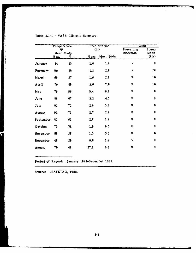
Table 3.1-1 - VAFB Climatic Summary.
Temperature Precipitation WindOF (in) Prevailing Speed
Mean Daily Direction MeanMax. Min. Mean Max. 24-hr (kts)
January 44 25 1.0 1.9 N 9
February 50 30 1.3 2.9 N 10
March 59 37 1.6 2.1 S 10
April 70 49 3.0 7.0 S 10
May 79 56 5.4 6.8 S 8
June 88 67 3.3 4.3 S 9
July 93 72 2.6 5.8 S 8
August 92 71 2.7 2.9 S 8
September 83 62 2.8 1.8 S 8
October 73 51 1.9 9.3 S 9
November 58 38 1.5 3.3 S 8
December 48 29 0.8 1.8 N 9
Annual 70 49 27.9 9.3 S 9
Period of Record: January 1942-December 1981.
Source: USAFETAC, 1982.
3-2
Great Plains physiographic province. Oklahoma has been divided into 22
geomorphic provinces as defined by the dominant land forms in each. VAFB
is within the Central Redbed Plains. This province covers a large part of
North-Central Oklahoma and is characterized by gently rolling hills cut into o
utcrops of Permian red shales, siltstones, and sandstones. The surface slope
of the area is generally eastward with a broad divide near Enid. KAux is
located in the Western Sand Dune Belts, areas of hummocky topography
which lie in comparatively narrow strips primarily along the north and east
sides of major streams. This is an area of stabilized sand dunes formed by
wind and water action on the sands of the braided stream channels
(Johnson, et al., 1979).
3.2.2 SURFACE HYDROLOGY
The area of North-Central Oklahoma containing VAFB and KAux lies within
the Arkansas River Basin. VAFB lies within the Cimmaron River sub-basin,
and KAux in the Salt Fork sub-basin. Other major sub-basins in the region
are the Chikaskia and North Canadian Rivers. All these rivers flow in a
generally southeastwardly direction toward the main stem of the Arkansas.
There are no natural lakes in the region, but man-made lakes such as
Canton Lake and the Great Salt Plains Reservoir are the major surface
water features of the area. They constitute an important recreational
resource and wildlife habitat.
The airfield and operating areas of VAFB are located on a topographic high
and are drained by a series of man-made ditches, which route stormwater
off the base as shown in Fig. 3.2-1. There is no on-flow of surface water
from off-base areas. All base property lies outside the 100-year flood plain.
In general, the north and central sections of the base drain to Boggy Creek.
This flow includes the discharge from VAFB sewage treatment plant (STP),
which is the only flow crossing the base boundary during dry periods.
Boggy Creek flows northeasterly approximately two miles before entering a
small municipal lake which is used for fishing and pleasure boating. Boggy
Creek subsequently joins Skelton Creek, which is tributary to the Cimmaron
River. The southern portions of the base drain into Hackberry Creek, an
ephemeral stream which passes through a series of agricultural impoundments
before joining Skelton Creek. VAFB is approximately 50 river miles from
3-3
i | .= ' .... . . .iml | . . ... .- j

-. 7NID CORIOATS BOUNDARY _ '~ 5 I30
................. ........
1 i r o Ii a
. .'. . . . 25
. . . . . #ge
VANCE U'~44 35 36fj :
3_ .. , / i' / ' -I I, . . . .
FI ORCE BAE ig-
• - *m.r ' eo4b
Iii .. " - "mJ . L Il .
Ii i - " l i II:1 I
U Im 6II (
fKEYI ~~ ~ -' -' --- - DRAINAGE .O11iNl BOUNDAIESl
C J/ IA '" -- -D DAINAGE HANNELS
(* OFFBASE DISCHARGE POINT
SCALE *-0 STP DISCHARGE
1000 0 1000 200O FEET 0 WATER QUALITY SAMPLING POINT
Source: VAFB. 1982.
Figure 3.2-1 INSTALLATIONDRAINAGE PATTERNS RESTORATION PROGRAM
Vance Air Force Base
3-4
the Skelton Creek confluence with the Cimmaron River. KAux lies
immediately south of the Salt Fork of the Arkansas River, draining directly
to the river through a number of small channels (Fig. 3.2-2). A man-made
impoundment near the eastern KAux boundary has been developed as a
recreational site by VAFB civil engineering.
3.3 GEOLOGY
3.3.1 GEOLOGIC SETTING
Geologic History
Two distinct intercontinental geosynelines or basins were formed in southern
Oklahoma during the Paleozoic era: (1) the pre-middle Devonian Wichita
basin, and (2) the Anadarko basin of late Paleozoic age (Caylor, 1957).
Maximum subsidence in the Wichita basin occurred along a line extending
west-northwest and east-southeast through southern Oklahoma and parts of
northern Texas. The Wichita basin was the site where great thicknesses of
late Cambrian, Ordivician, and Silurian-Devonian sediments accumulated.
These sediments are mostly massive marine limestones, which thin northward
but maintain a similar lithology into northern Oklahoma and the northern mid-
continent region. In the vicinity of VAFB, these rocks have an aggregate
thickness of some 3000 ft.
The initial rocks to be deposited in the marine waters which entered the
Wichita basin during late Cambrian time was a bed of arkosic sandstone
which is probably of wide areal extent and overlies Precambrian basement
rocks. Continued subsidence and deposition of massive marine limestones
(Arbuckle Group) followed in late Cambrian and Ordovician time. These
beds were probably deposited in shallow marine waters and were perhaps
derived from weathering of outcrops of igneous and metamorphic rocks of
the North American craton. Some evidence of subsequent weathering of the
Arbuckle group has been found at various places in northern Oklahoma.
Deposition appears to have been more or less continuous during late
Ordovician time.
In late or middle Devonian time, general emergence occurred over much of
the mid-continent region. These widespread crustal movements were
3-5

0InW 0
Wil 4
fl Z 0
-~~~6 LL.j~ ~/2~C
//jy i I -
39o
zoci
e. >
oI
SAM
Sim_ _
,I I" il.11) A
3-
accompanied by gentle uplifting of broad arches which extended in a
northwest-southeast direction through central Kansas, northeastern Oklahoma,
and southwestern Missouri. In the vicinity of VAFB the effects of these
uplifts were the regional southward tilting of early Devonian and older
rocks. The southward dipping rocks were subaerially eroded, and in most of
north-central Oklahoma the early Devonian and older rocks were totally or
partially removed.
Although the Nemaha uplift, to the east of VAFB and trending north-south,
was not developed until Pennsylvanian and early Permian time, a minor
positive element may have been present along a part of the Nemaha trend
as early as late Devonian time.
In Pennsylvanian time, the trough of the Wichita basin was compressed into
west-northwest and east-southeast trending fault blocks and folds in southern
Oklahoma. Just north of the uplifted Wichita Mountains, there lay an area
in which continued subsidence occurred. This area later developed into an
asymmetric intracontinental geosyncline or basin (Anadarko basin) in which
great masses of coarse clastics eroded from adjacent uplifts were deposited,
reworked, and spread as conglomerates, sandstones, and shales by marine
waters.
During the early phases of this orogenic activity in southern Oklahoma,
other portions of the mid-continent region were elevated. Structures along
the Nemaha uplift became prominent positive features, causing folding and
faulting of Mississippian and older rocks. In the vicinity of VAFB, these
pre-Pennsylvanian rocks were elevated and tilted gently to the south and
west.
At the end of the Pennsylvanian period gentle elevating movements of
regional extent occurred. More or less continuous deposition probably
occurred in the VAFB area at the same time erosion was taking place in
parts of Kansas. Where these movements succeeded in elevating the sea
floor above sea level, subaerial and wave erosion cut into the uplifted
Pennsylvanian rocks.
3-7
By the beginning of middle Permian time, land barriers probably caused the
marine water covering much of the mid-continent region to be restricted
from time to time, and with restriction came evaporation and subsequent
deposition of anhydrite beds. In the remaining Permian time, environments
varied from shallow marine waters to brackish and continental conditions.
Marine transgressions and regressions occurred, but with each succeeding
transgression the area inundated by marine waters grew more limited, until
finally, continental conditions prevailed and Permian sedimentation was
brought to an end.
Little can be said of Mesozoic or early Cenozoic deposits which may have
been deposited over the area, for all traces of rocks of these ages have
been removed by erosion.
Stream alluvium and terrace deposits were locally deposited in the
Quaternary and rest on the eroded, gently westward dipping Permian bedrock
of western Garfield County.
Structural and Stratigraphic Relations
VAFB - VAFB is located in the zone of intersection of the northern shelf
of the Anadarko basin and the Nemaha uplift. The northern basin shelf is a
structural platform of gently undulating surface that is tilted slightly to the
south-southwest. Generally, regional dip on shallow subsurface beds is a
few tens of feet per mile, increasing to approximately one degree on lower
strata. Structural contour lines drawn on subsurface beds indicate that a
west-northwest and east-southeast strike prevails over most of the shelf
area. However, moving eastward along the shelf near VAFB the strike of
the subsurface beds changes rather abruptly to essentially a north-south
direction. This change in direction of strike is brought about by the narrow
belt of related anticlinal structures which are the southern extension of the
Nemaha uplift, which marks the eastern limit of the northern basin shelf.
Recent earthquakes indicate that the Nemaha uplift is still active
(MacLachlan, n.d.).
3-8
The stratigraphic units encountered in north-central Oklahoma are listed in
Table 3.3-1. The regional stratigraphic column includes rocks of Quaternary,
Tertiary, Cretaceous, Paleozoic, and Precambrian age. Rocks of all
Paleozoic eras are represented.
As opposed to the trough of the Anadarko Basin, where continued subsidence
occurred over long periods of time and great thicknesses of Pennsylvanian
and Permian rocks accumulated, the northern basin shelf was a relatively
stable structural feature during middle and late Paleozoic time. The shelf
subsided discontinuously to receive mainly the thin platform correlatives of
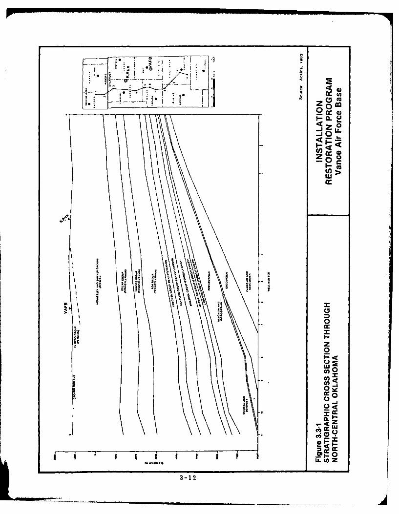
sediments being deposited along the basin trough. A north-south cross
section in the vicinity of VAFB and KAux, showing the southward dipping
strata, is presented in Fig. 3.3-1.
As shown on the geologic map (Fig. 3.3-2), VAFB is underlain by the Bison
Formation of Permian age. The Bison Formation is mainly red-brown shale
and greenish-gray and orange-brown caleitic siltstone with minor sandstone
(Bingham and Bergman, 1980). It is typically about 120 feet in thickness.
KAux - KAux is situated on Quaternary terrace deposits. These are
lenticular and interfingering deposits of light-tan to gray gravel, sand, silt,
clay, and volcanic ash. Sand dunes are common features in these deposits.
Thickness ranges up to 150 feet and averages about 60 feet.
The Quaternary terrace deposits in the vicinity of KAux overlie the Salt
Plains and Kingman Formations, both of Permian age. Where it occurs, the
Salt Plains Formation is underlain by the Kingman Formation. The Salt
Plains Formation is an orange-brown fine-grained sandstone and siltstone
with a greenish-gray sandstone in the middle 30 feet. The thickness ranges
up to 160 feet.
The Kingman Formation is an orange-brown to greenish-gray fine-grained
sandstone and siltstone with some red-brown shale. Thickness is about
70 feet.
The outcrop patterns of Pennsylvanian and Permian rocks in northern
Oklahoma were approximately the same in Jurassic time as they are today.
3-9

Table 3.3-1 - Generalized List of Stratigraphic Units ofNorth-Central Oklahoma. (Page 1 of 2)
System Series Group Formation
Holocene AlluviumQuarternary and
Pleistocene Terrace DepositsTertiary Pliocene Ogallala FormationCretaceous Comanchean Kiowa Formation
Doxey FormationFoss Cloud Chief Formation
Custerian Rush Springs FormationWhitehorse Marlow Formation
Dog Creek ShaleBlaine Formation
El Reno Flowerpot ShalePermian Cedar Hills Sandstone
Bison FormationCimarronian Salt Plains Formation
Hennessey Kingman FormationFairmont Shale
Sumner Garber SandstoneWellington FormationHerington LimestoneWinfield LimestoneFort Riley LimestoneWreford Limestone
Oscar Funston LimestoneCrouse LimestoneCottonwood LimestoneEskridge ShaleNeva Limestone
Gearyan Sallyards LimestoneRoca Shale
Pennsylvanian Red Eagle LimestoneJohnson ShaleForaker Limestone
Vanoss Hughes Creek ShaleFive Point LimestoneAdmire SandstoneBrownville LimestoneGrayhorse LimestoneReading LimestoneAuburn ShaleBird Creek Limestone
Ada Turkey Run LimestoneLittle Hominy Limestone
Virgilian Deer Creek LimestoneLecompton Limestone
3-10

Table 3.3-1 - Generalized List of Stratigraphic Units ofNorth-Central Oklahoma. (Page 2 of 2)
System Series Group Formation
Elgin SandstoneVamoosa Oread Limestone
Boley ConglomerateTallant FormationBarnsdall FormationWann Formation
Ochelata Iola LimestoneChanute Formation
Missourian Dewey FormationNellie Bly FormationHogshooter Limestone
Skiatook Coffeyville FormationCheckerboard Limestone
Pennsylvanian Ioldenville FormationOologah Formation
Marmaton Labette ShaleDesmoinesian Fort Scott Limestone
Wetumka ShaleCabaniss Calvin Sandstone
Senora SandstoneAtokan Dornick Hills Formation
(upper)Dornick Hills Formation
Morrowan (lower)Springer Formation
ChesterianMississippian Meramecian
OsageanKinderhookian
Devonianand Woodford Shale
MississippianSilurian
and HuntonDevonian
Sylvan ShaleOrdovician Viola Limestone
Simpson Bromide FormationCambrian
and ArbuckleOrdovicianCambrian Timbered HillsPrecambrian Metamorphic and Igneous
Rocks
Sources: Naff, 1981
Bingham and Bergman, 1980Johnson, et al., 1979MacLachlan, n.d.
3-11
CCU
0o
4-I--
0 LL
''~0,
100 X.10 1.
0.
So)
ISI)~~U _SVA1u-n
3-12e

KANSAS- --------
of &- OKLAHOMA JK -
(I\1Pfa Gal
at at ~ Pta Pg
at I01 % Pg
Pw
0. 0-- -. 1Fg
PtGRA FLOWRPO SHALE
PapN SALT PLIN FOMTOGal 1 ILS P PINS A FOMAIO
Pw WELINTO FOMAIO Mouon 1 0.1
Figur 3.32 1 ISTALATIOGELOICMP OFNRHCETA RSOAIO RGA
b.b
Therefore, the slight westward dip these rocks have on the surface was
imparted during post-Permian pre-early Mesozoic time. This gentle westward
dip has been referred to as the Prairie Plains homocline.
3.3.2 SOILS
Generally, the soils at VAFB are fine sandy loams with medium fertility,
gently rolling and well-drained. Many of these soil series contain clay
layers 2 to 4 feet below the surface. These layers are generally
discontinuous and do not constitute an aquiclude. Soils associations are
shown in Fig. 3.3-3. The five series represented can be briefly described as
follows (USSCS, 1967):
Bethany: This series consists of deep, medium-textured, and nearly level
upland soils. The surface layer is a moderately permeable (0.8 to 2.5 in/hr)
silt loam. The subsoil is a mildly alkaline clay 24 to 36 inches thick.
Pond Creek: In this series are very fertile, well-drained soils with a
moderately to slowly permeable (0.05 to 0.8 in/hr) subsoil. These soils are
nearly level to very gentle slopes on uplands, primarily west of the base.
The surface layer is a granular silt loam 12 to 16 inches thick, underlain by
a silty clay loam about 34 inches thick.
Tabler: Found in nearly level areas and slight upland depressions. These
soils consist of a moderately well-drained surface layer of silt loam about
8 in thick. The permeable surface layer is underlain by a transition layer
of heavy silt loam 2 to 4 inches thick, which is in turn underlain by a
clayey subsoil about 36 inches thick.
Grant: These soils are nearly level to moderately steep and have a 16-inch
surface layer of moderately permeable silt loam. Subsoils are about
31 inches thick, consisting of porous to moderately permeable silt loam or
light clay loam.
Kirkland: These are nearly level to very gently sloping upland soils with a
surface layer of granular silt loam generally about 12 inches thick. The
3-14

KrB - -rB
BA
KrB______ 2
)a
AIR FORC BASAERNRO IT OM
Source USSC 1967
Figure %. NTALTO
SOIL TYPESRESTORATIONPOGAea AirAN Force BOAM01%seO
3-1RNTSL5OA,13%SOE

subsoil is a very slowly permeable (less than 0.05 in/hr), blocky clay about
32 inches thick which is extremely hard when dry. Internal drainage of
these soils is very slow.
Soils at KAux vary from those at VAFB, reflecting the different geomorphic
settings. The primary soil series at KAux are briefly described below and
are mapped in USSCS (1975):
Albion: Soils in this series consist of nearly level through moderately steep,
well-drained and somewhat excessively well-drained uplands. The surface
layer is a sandy loam about 8 inches thick. Subsoils extend to a depth of
about 32 inches and consist of sandy loam with moderately rapid (2.5 to
5.0 in/hr) permeability.
Pratt: These are nearly level to sloping, well drained soils on uplands. The
surface layer is a loamy fine sand about 9 inches thick. The subsoil is a
loamy fine sand with rapid permeability (5.0 to 10.0 in/hr), which extends to
a depth of about 42 inches.
3.3.3 GEOHYDROLOGY
Precipitation is the source of nearly all ground water in the vicinity of
VAFB. Although winter is the driest season, most ground water recharge
occurs from November to April when evaporation and transpiration are at a
minimum. Ground water recharge to the Cimarron terrace southwest of
VAFB has been estimated to be 14.5 percent of the average annual
precipitation (Bingham and Bergman, 1980). Recharge to other terrace
deposits and to alluvium in the vicinity of VAFB may be about the same
amount because the surface soils are sandy and capable of absorbing large
amounts of water and because the lithologies of the aquifers are similar.
Amounts of recharge to bedrock aquifers are unknown but undoubtedly are
considerably less than recharge to terrace deposits and alluvium. The
amount of water that can enter the soil and percolate downward to the
underlying bedrock is limited because soils in the recharge area of the
bedrock generally consist mostly of clay which has low permeability.
3-16
Ground water movement generally is from the uplands towards the streams.
Seepage to the streams and evapotranspiration account for most of the
ground water discharge. During dry periods, seepage from the aquifers is
the source of base flow in the streams. Small streams in the area
frequently go dry because the fine-grained sandstone and shale underlying
the area have a limited capacity to absorb and transmit ground water.
Along the major streams the alluvium is thick enough to absorb and transmit
large amounts of water, maintaining base flow in the major streams. During
wet periods, however, when the stream level is higher than the water table
in the adjacent alluvium, seepage from the stream through the stream bank
is a source of recharge to the alluvium.
Two principal aquifers are recognized in the VAFB area: the alluvial
aquifer and the Cedar Hills aquifer. The approximate distribution of the
aquifers is illustrated in Fig. 3.3-4.
The alluvial aquifer includes both alluvial and terrace deposits and is
composed of silt, clay, and fine sand with coarse sand and gravel at the
base in some areas. The alluvial aquifer located along minor seams is
composed of fine-grained sand containing varying amounts of silt and clay;
thus, the permeability is generally low. Well yields in the alluvial aquifer
range from 50 to 600 gallons per minute (gpm) in river and terrace deposits
to 25 to 50 gpm in areas adjacent to minor streams. Enid obtains its water
from terrace deposits which surround the city and from alluvial and terrace
deposits adjacent to the Cimarron River.
Aquifers in the bedrock are composed of saturated sandstone layers
irregularly interbedded with shale, siltstone, and limestone. Most of the
sandstone layers are fine-grained, thin, and commonly yield only enough
water for household use. Locally, however, part of the sandstone is medium-
to coarse-grained and yields as much as 200 gpm to industrial, irrigation,
and public-supply wells. The Cedar Hills aquifer, the bedrock aquifer
nearest VAFB, is mostly fine-grained sandstone interbedded with siltstone
and shale. The potential well yields are estimated at 150 to 200 gpm.
3-17

- -A - -S - -SOKLAHOMA
<11
- K I(
DRUMM0N!
J:OULA
AORlfEL---------AFEjNSE
MEDOR
RE SLj WAR iN HS RA SDRVDMSL FO H HC ADADGAE O l UTRAYALVA N
---ROUP-- -- -- -YIELT S-ALL AM UT-O-AE-A OT CS
--- I--OU-TY-LINE
EA* CITYTOW
.......... HIGLFWAY
5 0 5 1 M ILSuc iga n ega.igoM60n.18
Figure.......3- 1..IN.TALLATIONPRNCPA AQUIFERS.O.RESTORATON.PROGRA
NORTH ..CENTRAL. OKAOM AaneAiBoceBs..........

The remainder of the area, including VAFB itself, is underlain by minor
local aquifers. Ground water occurs in strata that are predominantly shale
with some siltstone and fine-grained sandstone. Recharge is from local
precipitation and well yields are small, typically 3 to 10 gpm. Waukomis
obtains a portion of its municipal water from nine wells located three miles
south-southwest of VAFB. The wells are 60 feet deep and have yields of
approximately 25 gpm. These wells provide water to 1500 persons.
Soil borings at VAFB shown in Fig. 3.3-5 indicate that in the vicinity of
Bldg. 672 water occurs in an orange, silty clay at depths of 6 to 13.5 feet
(VAFB, 1982). Bedrock at these locations is described as an orange, silty
shale and is found at depths of 10 to 13.5 feet. In one boring, located at
the north corner of Bldg. 672, water was found in a clayey silt stratum at
a depth of 2 to 3 feet.
At Bldgs. 690 and 810, east of Bldg. 672, bedrock was encountered at
depths of 11 to 18 feet without any water-bearing strata identified in the
overlying unconsolidated materials. The bedrock was described as a sandy
clay-shale in the vicinity of Bldg. 690 and a reddish-brown, fine-grained,
silty, clayey, shaley sandstone at Bldg. 810.
Near Bldg. 410, a wet stratum was found at a depth of 9 to 22 feet and
bedrock (red shale) was encountered at 20 to 23 feet.
The occurrence of ground water at VAFB appears to be highly variable and
in low-permeability strata. The available data are not suffficient to
determine direction and rates of ground water movement.
KAux, while not underlain by a principal aquifer, is adjacent to the Salt
Fork alluvial aquifer. The deposits along the Salt Fork River attiin a
maximum thickness of approximately 60 feet with a maximum saturated
thickness of about 35 feet (Vance, 1976).
3.4 WATER QUALITY
3.4.1 SURFACE WATER
VAFB is drained by small intermittent streams. Surface water quality
monitoring has been restricted to the STP effluent, the north drainage ditch
3-19

0*9
-S
is V I 7I
.Ijy1 -.*U\ ~c
'(cc~ >
~ +~VfdS hf I-o.
* £~,J" *cc®rID
0- 11
i.: -
3-20
(Boggy Creek) below the STP discharge point and the south drainage ditch
(Hackberry Creek). Both drainage ditches are sampled near the base
boundary. The locations of these sampling points are shown in
Fig. 3.2-1.
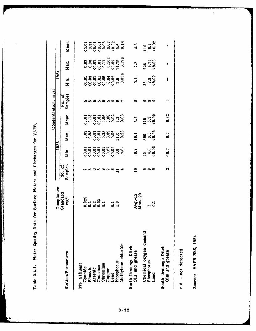
Water quality data for these stations are summarized in Table 3.4-1. The
compliance standards shown in Table 3.4-1 are obtained from Oklahoma
Water Resources Board Permit No. WD-79-021, which currently regulates
water quality at the three VAFB sampling points.
The data indicate that concentrations phosphorus in the STP effluent often
exceed compliance standards and that phenols and chromium concentrations
are occasionally in excess of standards. The north drainage ditch water
quality is greatly influenced by the STP effluent, which at times comprises
the majority of the flow in the ditch. Phosphorus concentrations in the
ditch exceed the compliance standards, and the chemical oxygen demand is
higher than would be expected in most streams.
The south drainage ditch is often dry and has been sampled on only two
occasions. In both instances, the oil and grease concentrations were
relatively low.
The available water quality data are somewhat limited in parametric
coverage and do not eliminate the possibility of contamination existing to an
undesirable extent. For example, the oil and grease analyses in the
drainage ditches would not detect low-level, but potentially toxic, releases
of trace halogenated or nonhalogenated organics or polychlorinated biphenyls
(PCBs).
The small streams draining KAux have not been characterized with respect
to water quality. The Salt Fork, adjacent to KAux and the receiving water
body for streams draining KAux, reportedly has poor water quality due to
high dissolved solids concentrations (Morton, 1980).
3-21
0== 0c '0 00 -4 m. I t:
C)~
c; c; C; c; C.-4 0V %/ V -4 4 4
00 CD =f. C)4 = =4c; 00 0~ 6 ;C;c-A C4 C0
VVV % v4 mq v
(0
Ln ll Ulltn o n lam - IfM 0)O0 0o 02
C4 -4= C m c !)
0L)
-4 o- r l m c mU
> 0!99,1990 Cl! .- e!O
0 C*
0)- - 4 4UME
d) CD eq=4 = cmc =4
0 . C; oo o C0 eO 8 ;efC z nw ; C
od vvvvv v e4 v V/
C))
40 4
z c
C 0
C))
E =C)C C ) cmII440 4 C 24m 4= 4= 4-q ,4=
0
-44a01
-0 cc0 w0. .0 to 5 .
I- *- C). V ?A03 o 0 0 4
0. 0 )CO0 0 -4 33 E Zo L .. 3
2 0 0zC
a.3-2 0
3.4.2 GROUND WATER
Due to the absence of wells on VAFB and KAux, the quality of ground
water beneath the installation has not been characterized. Some information
regarding the general characteristics of ground water in the vicinity of
VAFB can be obtained using data from adjacent areas, however. The
discussion of ground water quality provided in the following paragraphs was
obtained from Bingham and Bergman (1980). Locations of wells from which
ground water quality data were obtained were not provided.
Chemical characteristics of ground water in the Enid area differ
considerably within short distances. [n general, the water is hard or very
hard and locally contains sulfate and chloride in excess of 250 milligrams
per liter (mg/i). Samples of water from some shallow wells contain more
than 45 mgfi nitrate. The dissolved solids concentrations of water samples
range from 60 to 6,000 mg/I and average about 650 mg/l.
Sulfate in ground water is derived from such minerals as gypsum and
anhydrite (calcium sulfate). Chloride is derived from halite (sodium chloride)
and brines and from human, animal, and industrial wastes. Small amounts of
chloride have little effect on the usability of water for most purposes;
however, water containing chloride in concentrations of several hundred
milligrams per liter has a salty taste.
Nitrate in water is considered to be a final oxidation product of nitrogenous
material, and when present in concentrations greater than about 45 mg/l
may indicate contamination by sewage and other organic matter. Chemical
fertilizers also may be a source of nitrate. The quantity of nitrate present
in natural, unpolluted water generally is only a few milligrams per liter.
Calcium is dissolved from many rocks, but higher concentrations generally
are found in water that has been in contact with limestone (calcium
carabonate), dolomite (calcium magnesium carbonate), or gypsum; magnesium
is dissolved primarily from dolomitic rocks. Both calcium and magnesium
contribute to the water's hardness, which reduces the cleaning action of
soap and detergents and which has scale-forming properties.
3-23
Dissolved solids consist principally of dissolved minerals and organic matter
in the water. A dissolved solids concentration of 500 mg/l is considered the
recommended upper limit for drinking water and for most domestic and
industrial uses.
Some mineralization of ground water in the vicinity of VAFB might be due
to contamination by oil-well brines, particularly in the vicinity of oil fields.
Such contamination may be the result of seepage from waste pits, defective
well casing, defective well plugging, water-flooding operations, or improper
brine disposal.
The Garfield County Health Department has not received any reports of
ground water quality complaints other than excessive hardness and chloride
concentrations.
The total population within 3 miles of VAFB using local ground water as a
potable water source was estimated to be less than 50 south and east of
the installation and between 50 and 1000 north and west of the base.
Potable water for VAFB is obtained from the City of Enid, and KAux
potable water is obtained from a well north of KAux. Samples of both
water sources have been analyzed and found to be in compliance with
National Interim Primary Drinking Water Regulation (NIPDWR) standards.
3.5 BIOTA
VAFB is located in the central rolling red plains region of Oklahoma. No
areas of undisturbed vegetation remain on the base. Dominant vegetation
are grasses, chiefly Bermuda grass and rye grass. Principal tree species are
honey locust, cottonwoods, and several species of conifers. Prairie areas on
VAFB include a mixture of native and introduced species such as Bermuda
grass, weeping love buffalo grass, blue stem, rye, blue grama grass, and
dropseed.
Wildlife activity on VAFB is limited due to small amounts of suitable habitat
and by high levels of human activity. Mammals which inhabit the base
3-24
include cottontail rabbit, blacktail jackrabbit, badger, striped skunk, coyote,
racoon, and deer mice. Meadowlarks are common. Reptiles which occur on
the base are the bullsnake, western hognose snake, and several species of
lizards.
No threatened or endangered species regularly inhabit the area. The
southern bald eagle, whooping crane, and American peregrine falcon have
been observed in the vicinity of VAFB, but suitable habitat does not exist
on base for any of these species.
Habitats in the KAux area include willow, cottonwood, and black locust
woodlands interspersed with prairie grasslands. Wildlife include whitetail
deer, racoon, striped skunk, eastern fox squirrel, bobcat, coyote, badger,
opossum, crow, pheasant, mourning dove, turkey, and several species of
quail. The availability of suitable habitat and the proximity to water on
KAux account for the greater variety of wildlife found there. In addition
to the southern bald eagle, whooping crane, and American peregrine falcon,
additional threatened or endangered species observed in the vicinity of KAux
are the prairie falcon, golden eagle, sandhill crane, and blacktail prairie
dog.
In addition to the principal species indicated above, both VAFB and KAux
are host to a larger number of other migratory and resident wildlife species.
Located north of KAux is the Great Salt Plains National Wildlife Refuge.
This refuge provides habitat for many wildlife species.
3-25
4.0 FINDINGS
This chapter presents information for VAFB on wastes generated by activity,
describes past waste disposal methods, identifies the disposal and spill sites
located on the base, and evaluates the potential for environmental
contamination. This information was obtained by a review of files and
records, interviews with present and former Air Force and base employees,
and site inspections.
4.1 ACTIVITY REVIEW
4.1.1 INDUSTRIAL OPERATIONS
All the major current and past industrial operations at VAFB relate to the
maintenance of the aircraft used in pilot training. The different levels of
maintenance and the various operations are conducted by several different
organizations at a number of locations on the base. Operations include
engine repairs/overhauls; electrical, hydraulic, and fuel system repairs;
painting; metal plating/finishing; and support equipment maintenance. No
industrial activities are conducted at KAux.
The basic mission of VAFB has remained essentially the same since the base
was first activated. However, over that period the type of aircraft being
flown has changed several times. Between 1942 and 1956, propeller-driven
aircraft were used. These were followed by the T-33 between 1956 and
1960. The T-37 was introduced in 1960 and was joined by the T-38 in
1964. The materials, construction, and maintenance requirements of these
earlier aircraft differed from those currently in use. Thus, the specific
equipment and materials used in current maintenance operations may not
reflect the 10 years prior to 1960, although the categories of maintenance
being performed and locations where they are conducted have changed little.
Scheduled maintenance, including oil and fluids changes and other routine
items, is performed in the T-37 and T-38 maintenance shops located in
Bldgs. 195 and 141, respectively. Heavy and nonscheduled maintenance for
both aircraft is performed in a separate facility at Bldg. 129. Engines
4-1
requiring major repair or overhaul are removed from the aircraft and taken
to Bldg. 187, which is equipped with facilities and equipment for such
operations. Painting of parts is conducted in the Bldg. 128 paint shop,
while the aircraft are painted in Bldg. 192, and motor vehicle painting is
done in Bldg. 298. All these locations are equipped with liquid curtain
spray booths, and Bldg. 192 is specially fitted to accommodate the large
scale stripping operation required for complete aircraft repainting. Metal
treatment operations are conducted in the plating shop at Bldg. 128, and in
Bldg. 187, the jet engine shop.
Other training activities at VAFB in addition to pilot training include
firefighter training. Fire training exercises are conducted regularly using
JP4 as fuel and using water and AFFF as suppressants. The KAux fire unit
conducts similar exercises at the KAux firefighter training area in an
unlined pit approximately twice a year.
4.1.2 FUELS/OILS HANDLING AND STORAGE
The main fuel used at VAFB is JP4 jet fuel. Additional fuels and oils
stored and used in quantity are gasoline (MOGAS), diesel fuel, and 7808
engine oil. The largest storage points are Tanks 265 and 267, both located
adjacent to the west gate. These tanks provide above ground storage of
JP4 and normally contain a combined quantity of 605,000 gallons (gal).
Secondary containment at this location is provided by an asphalt-sealed
earthen berm enclosing an unlined area. Various underground tanks ranging
in capacity from 3,000 to 25,000 gal are used to store the other products
(see Table 4.1-1).
Refueling of aircraft is performed on the flight line. Fuel is transported
from the storage tanks in tank trucks with capacities of 3,000 to 5,000 gal.
On occasions when refueling is required at KAux, fuel is transported in atank truck from VAFB. Trucks are filled from a transfer point at the north
end of the flight line. No secondary containment is provided at this
location. All planes on the flight line are normally kept full of fuel. The
T-37 holds 309 gal and the T-38 holds 583 gal. Personnel from base fuels
4-2

Table 4.1-1. POL Storage Tanks
Capacity TypeTank No. (gallons) Above/Below Ground Contents
265 250,000 AG JP4267 675,000 AG JP4
90-99 10@25,000 BG empty87 12,000 BG MOGAS88 12,000 BG MOGAS
106 12,000 BG Diesel108 12,000 BG Solvent109 12,000 BG empty112 12,000 BG Waste Oil522 10,000 BG MOGAS522 204,000 BG MOGAS522 3,000 BG MOGAS
Source: ESE, 1984
4-3
operate and maintain the fuel storage and distribution system. Storage
tanks, valves, and piping are inspected daily to check for conditions which
pose a fire or spill hazard.
4.1.3 PESTICIDE/HERBICIDE HANDLING AND STORAGE
The mixing and bulk storage locations for pesticides/herbicides at VAFB are
Bldgs. 255 and 194, respectively. Small containers of some materials are
stored in Bldg. 284. Handling, storage, and applications of pesticides and
herbicides is carried out in accordance with the VAFB Pest Management
Plan and applicable state and federal regulations. There are no stocks of
restricted pesticides on hand. Both Silvex and 2,4,5-T were once used on
the base, but remaining stocks of these materials were turned in to DPDO
when restrictions were imposed.
Waste generation associated with pesticide and herbicide use is limited to
empty containers, rinseate and wastewater generated from cleaning spraying
equipment. Since 1968, when an entomologist was first assigned to the
base, containers have been triple-rinsed and disposed of as solid waste with
the rinse water used in subsequent mixing. Until recently, spraying
equipment was washed at the wash rack at Bldg. 270. The rack drains to
an oil/water separator which is periodically pumped out and the material is
drummed for contract disposal. Washing was recently moved to a new
facility at Bldg. 255, which drains to the sanitary sewer through a grit trap.
Prior to 1968, pesticide/herbicide application was conducted on a limited
spot basis, and disposal procedures are undocumented.
4.1.4 PCB HANDLING AND STORAGE
Analyses have been performed on 93 transformers at VAFB of which 12
were found to contain PCB's at greater than 500 ppm and an additional 20
were found contaminated with PCB's at levels between 50 and 500 ppm.
These transformers are currently stored in the hazardous waste storage area
north of Bldg. 193. These transformers are part of a group of over 200
which were taken out of service in 1983 during an upgrade of the VAFB
electric distribution system. All these units, including 125 which have not
been analyzed, will be disposed of through contract off-base.
4-4
No record was found of PCB spills or on-base disposal of transformer oil.
However, electric shop personnel reported that transformers which required
replacement were stored in the Civil Engineering Salvage Yard near the
West Gate and were drained onsite before being turned over to DPDO. This
oil may have been disposed of by mixing with other waste oil generated, but
this procedure was not documented.
4.2 HAZARDOUS WASTE GENERATION/DISPOSAL
4.2.1 GENERATING OPERATIONS
VAFB engineering personnel provided a hazardous waste inventory conducted
in June 1980. This listing was used as the basis for identifying shops on
the base and making a preliminary assessment of the types and quantities of
waste generated by the various operations. Interviews were conducted with
personnel from each of the major waste generation points. Telephone
contacts were made with smaller operations. In each interview, personnel
were asked to verify or update the types and quantities of waste generated
as reported in the 1980 survey. By locating personnel who had long
employment histories, information was obtained on how waste generation
patterns had changed over the years. These interviews also provided the
information on disposal methods presented in See. 4.2.2.
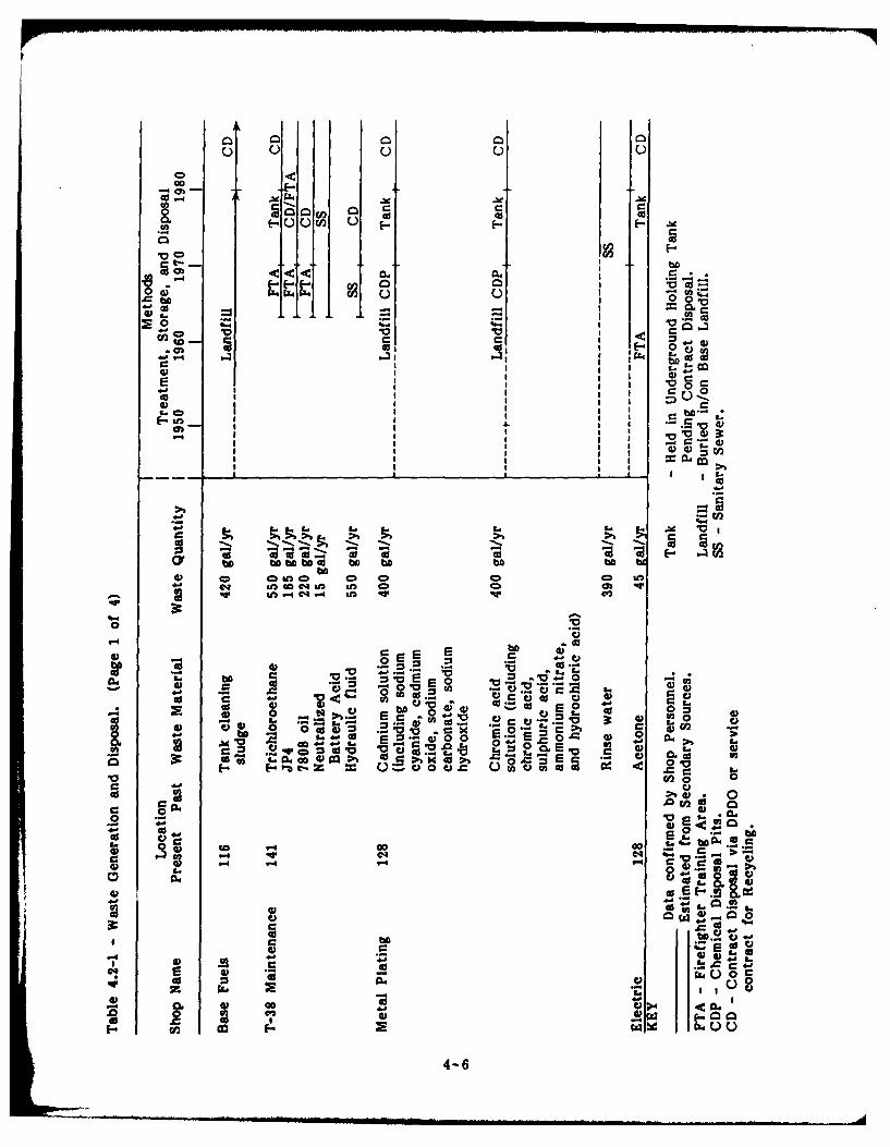
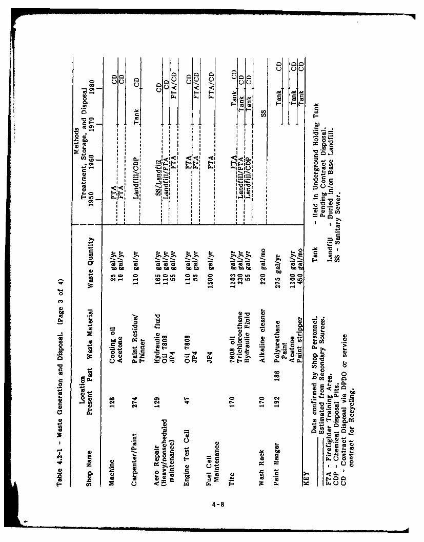
Information obtained on the major waste generating operations is summarized
in Table 4.2-1. Not all the wastes 1Usted are hazardous wastes as defined
by EPA, but have been included to provide a complete picture of the range
and quantity of waste generated which require controlled disposal. A
master list of facilities and shops at VAFB and their waste generation
status is presented in Appendix D.
The main types of waste generated at VAFB are fuel, oils and solvents,
paints and paint strippers, and metal plating/treatment solutions. Waste
fuel, oil and solvents include JP4, engine oil, PD680, and acetone, which are
derived primarily from periodic maintenance and engine repair operations,
but are generated in small quantities at almost all the maintenance shops.
Waste consisting of paint residue, strippers and thinner is generated by the
parts, aircraft, and vehicle painting operations. The aircraft painting
operation, which is one of the largest waste generators on the base, was
4-5
000
M0 U C) f ~ Udfcd ,
an 0
S00~ S
0
0 CD "0 r_
W- : 3
I= 0
CD -0
CD 4) I
cy ba o bb.bA do b Obf b
4) C2 0 LI 0D CD 0D CDCDeq UM n cc0 S n CD eDC
'r n "C4 .4 Sn W -
0
0d - a 00 0-
0 0. -- C C)~0 CV 00 0o C)5
*k W~ ad 0 '0 ~ 0= 0
*0 10l 0
0) 0~' w 1 ,0r
Go 0
- y*4 0WC - ->bV d 9
L- bA C) 0 4.' C~a= "r
24 o -s
V 0
0 . ) ..0 ~~ 7 .3 - 0
FV- cnm F a
4-60

a) 0 En LM0
bD
I- II i
0 o
0" 1- ~ ba.i I
1- 0 0i 0 00 '0 0 0
I ~~0 bbI bI bII.Q
00
*-C1
0 Z
Go0 00 3: U)
OD 4). U, ~ fc ) i O O ~ 4
C4.CL 0 U
VS C' ocL 6co U
1- .~00c in0
~ ad
-- eq C4* m04
0.. C)~b
0-
.41
0 Cc _
.X0o =
0- 25 I 2 C4 .!0 .
<0 &w *~ 44-7
00) 0) 0
00a
0 cfl
F-E - -F.) gg.P 44 SI 44 c
(DIc I cu 0o0 .0'a. CD CI n
II, 44
-~ 0' - F-F-' FI 0
Ii I I~Lal
0 t cc 0'~ -5
In Im CD to0 n C o 4 -3=u) 4 m*C4 '< -4 "4 to 14i O = CDmI q t z&
tF- 0'l mI0 L- vI 4
0 9
I g II I I IW -0
0Ii I
II97 Il cII I I I
wn~b ba 0
Cfl 0. v~u 0U) 0 C'0l 00
r0 or ' c
0. 0 *.-
40C . 0 C o - Al to
0 >b;5 CL,. 5 C 00 0 C)
0
0~~c 00 -. 0.. ~~ ~C) a
C- 9. 0
co -V CD~a 0-S- 4.'* - 4t-
04i~
0 ~ E- 4
oo m
C)1 4) ccl. Ci0. 01 -v-
0
06 F-~~~ Cd 0 4)- ~ .
44-

Q2u 00 uC-
o-bdW C
?Ar- r
a ~I I- E-Eb
n cc0 4;'
11 1 I :1III
CISi I I
E~~~~. ±C4 L -Jd
r- 0
- 4
to U4- 0 .~04
~ cis
fI ~b~O~nfl bD bO bfl bn 0
- fC) DLOCmUl C CD Ccc ) 0 0z CD 1JD cz -4 I
0
00
i -as
0 0 to 0
L. .00
CD qw C)bn i: v
G 0 0 >% Go 2L A~ o &o
L- UEo CA00 0 0l
oo
0 t-Cq 00cmbIle CM "t- C
-4 00
E E1 J4 (0. 4 04
icO~A V -4
0o >0)2 ~ ) ) 4 0 Z 4 001 1 C)
4-9
begun in 1970, but only reached the current level of activity in 1980 when
a program to repaint the entire fleet was initiated. Metal plating/treatment
waste is generated at the jet engine shop and metal plating shops and
consists of phosphoric acid, chromic acid, potassium permanganate, cadmium,
and descaling solutions.
The fire suppressant currently employed at VAFB and KAux is AFFF.
Available information suggests that, at least in some applications, carbon
tetrachloride may have been employed until approximately the mid-1950s.
The use of chlorobromomethane may have followed carbon tetrachloride and
may have been utilized until the early 1970s. The extent to which these
suppressants were utilized and the manner of their disposal at VAFB and
KAux could not be substantiated.
4.2.2 DISPOSAL METHODS
The information obtained on waste disposal practices is summarized
graphically in Table 4.2-1. The general trend over the years since VAFB
first began operation has been from largely unsegregated disposal in base
landfills toward extensive waste segregation and contract disposal. Prior to
1960, it was reported that virtually no waste segregation was practiced, and
containerized liquids from industrial operations were routinely buried in base
landfills. However, over this same period, the firefighter training area was
used as a general disposal area for fuel, oil, and solvents, so it is doubtful
that much of this material ever reached the landfills. Also, most burnable
trash was incinerated on base, and some edible garbage was sold as hog
feed to local farmers. Information from this early period is difficult to
substantiate. It is likely that small quantities of liquids were disposed of in
the sewers or dumped on surface soils.
By the early 1960's, the practice of digging dedicated pits for disposal of
some industrial waste was in use. The material disposed of in this manner
reportedly consisted mainly of metal plating solutions and sludges from fuel
tank cleaning, but may also have included other industrial liquids and
infectious waste from the base hospital. While landfilling of solid waste and
trash incineration on the base were discontinued by 1965, disposal pits were
reportedly used until approximately 1970.
4-10
Waste disposal practices at VAFB changed substantially in the early 1970's.
Collection of waste fuel, oils, and solvents for contract reclamation off-base
was initiated, and the current system for contract disposal of unusable
quantities began. Flammable liquids used in fire training was restricted to
JP4 only, and existing lined firefighter training pit was constructed. The
practice of using pits for chemical and sludge disposal was replaced by a
system where these materials were stored in an unused underground fuel
tank near Bldg. 110 and eventually removed for contract disposal.
By approximately 1980, the present system for chemical and sludge disposal
eliminated the need for temporary storage in the underground tank. Wastes
are containerized in 55-gal drums, labeled according to DOT and EPA
regulations, and held at the fenced accumulation point north of Bldg. 122
for contract disposal. Ultimate disposal is arranged through VAFB's
designated DPDO at Tinker AFB, Oklahoma. Industrial waste disposal on the
base is now limited to liquid waste from the paint stripping operation in
Bldg. 192, which is metered into the sanitary sewer and processed through
the base sewage treatment plant. Sludge from the treatment plant has been
analyzed and a Sludge Management Plan is being prepared.
4.2.3 SPILLS OR INCIDENTAL DISCHARGES
The VAFB SPCC plan indicates no record of spills except minor losses
during fueling of aircraft. Base fuels personnel confirmed this, reporting no
spills requiring emergency response or cleanup efforts.
4.2.4 OFF-BASE DISPOSAL SITES
Available information indicates that materials originating at VAFB are
currently directed to three disposal sites. Solid waste is transported to the
City of Enid landfill through a local contract. ' vardous and liquid waste
are disposed of through arrangement with Tinker AFB DPDO. Since 1980,
VAFB has contracted with a hazardous waste incinerator in El Dorado,
Arkansas; the EPA-permitted hazardous waste landfill at Lone Mountain,
Oklahoma; and Chemical Waste Management in Port Arthur, Texas. Before
1980, VAFB contracted for waste disposal at a landfill in Criner, Oklahoma,.
4-Il

and the Conservation Chemical Company landfill in Kansas City, Missouri.
Both sites are under study as part of the EPA Superfund program.
4.3 AREAS OF POTENTIAL CONTAMINATION
This study identified eight areas on VAFB subject to contamination by
industrial and/or hazardous waste as a result of handling and disposal
practices. Figures 4.3-1, 4.3-2, and 4.3-3 illustrate the locations of these
areas. Aerial photographs of each site are provided in Appendix E.
Tank Farm Landfill
The Tank Farm Landfill site is located on the north base boundary, adjacent
to the west gate and the main JP4 storage tanks. This site was used as a
general purpose landfill during the years before 1952. The landfill was
operated by the trench and fill method, with the trench bottom at a depth
of approximately 15 ft. Personnel that operated this site from 1948 to 1951
reported wastes consisted mostly of household solid wastes, but no
restrictions were placed on items dumped, and other wastes including
containerized liquids were routinely landfilled. It was reported that some
tank sludge from leaded gas tanks was buried under the berm around Tank
267 before that facility was constructed. Most of this area is currently
open and unused, although the filled area is thought to extend part way
under the existing JP4 tanks.
East Boundary Landfill
In approximately 1952, landfilling activities shifted to the East Boundary
Landfill located on the east base boundary adjacent to the pistol range and
base clinic. This site was operated as a general purpose trench type
landfill for approximately five or six years. Material deposited here was
predominately household solid waste and possibly industrial liquids. Trenches
were dug to approximately 15 ft deep, and waste was covered with the
excavated material. This is currently an open area which is cultivated as
garden plots by base personnel.
Southeast Landfill
From approximately 1958 to 1965 trench and fill disposal of solid waste
proceeded through the Southeast Landfill area. This is currently an open
4-12
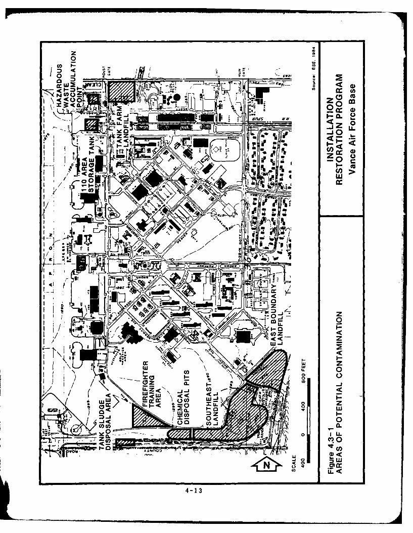
z 'co
r- (a5 2_ 4 2
(5 cc,
L
zzz160
w
dat-**lil /-N4 ~ _its
w g, Ell
4-D
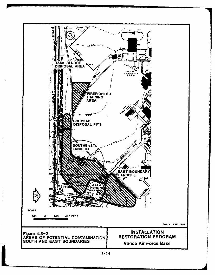
\Vg" o,,4 .
TANK SLUDGEDISPOSAL AREA
/, GOLF
FIREFIGHTERTRAINING
0AREA
CHEMICAL
Figure DISPO-2 INTALAIO
EAST SOUNDAFLANDFILL
SCALE
200 0 200 400 FEET
Sowrce: ESE. 1984
Figure 4.3-2 INSTALLATION
AREAS OF POTENTIAL CONTAMINATION I RESTORATION PROGRAMSOUTH.,AND,,A, T OUNDARIES,,,,o Vance Air ForceBase~4-14

/0 X
SCALEVAG
Sou.e 1E 1984
Figure4.3-3INSTALATIOAREAS1O POETA RESTOATERGASTOAGETANAT0610 ACUMLAIO
WEST-26 GATEARAVneArFceBs
294[:4-15
area between the roadway and the south boundary drainage ditch, the
northern portion of which is used to store fill material and dried sludge
from the sewage treatment plant. This landfill reportedly contains little if
any industrial waste, as other methods for disposing of such material were
used during part of the period it was operated. Base personnel report this
area once sloped toward the south, but extensive placement of rubble fill has
raised the surface to nearly level. The solid wastes are believed to be 10
to 20 feet below existing grade. Aerial photographs substantiate the
presence of rubble fill in this area.
Chemical Disposal Pits
The Chemical Disposal Pit area is located between the south boundary
drainage ditch and the existing roadway. This area was active from
approximately 1960 to 1970 and was used for disposal of metal plating
solutions, hospital waste, and possibly other industrial liquids. Pits
approximately 10 to 12 feet deep were dug randomly in the area on an as-
needed basis. Liquid wastes were then poured into the pit, and it was
gradually refilled with the excavated material as the liquid soaked into the
soil. It was reported that this took place approximately twice each year,
with approximately 500 to 1,000 gal being dumped on each occasion. The
area was subsequently used for rubble and fill dumping which leveled the
original slope to the south, and it is estimated that the disposal pits are 5
to 10 feet below existing grade. This is currently an open, unused area.
Tank Sludge Disposal Area
Located between the drainage ditch and the south base boundary, the Tank
Sludge Disposal area was used on a one-time basis in 1967. The sludge
generated from a fuel storage tank cleaning program was transported to the
site and buried in a large pit. The waste was covered with the excavated
material. The quantity of waste buried in this currently unused area was
not reported. Base fuels estimates cleaning of the JP4 tanks generates
approximately 1000 gal of sludge.
Firefighter Training Area
The area where the existing Firefighter Training Area is located at the
southern end of Elam road was reportedly used as a dumping area for a
4-16
variety of flammable liquids until approximately 1970. These liquids, which
included fuel, oils, and solvents, were reportedly dumped in a shallow
depression in the ground surface and periodically ignited during training
exercises. No reliable estimates were available of quantities dumped, as this
was an uncontrolled process. The existing fire training pit, a lined basin
with provision for fuel storage and runoff control, is located on the site.
This facility was upgraded in 1983 by addition of an oil/water separator on
the drain line.
Bldg. 110 Area Storage Tank
From approximately 1970 to 1980, an unused fuel tank adjacent to Bldg. 110
was used for storage of a wide variety of materials including waste
solvents, metal treatment solutions, and waste oils. Although no waste has
been contributed to the tank since 1980, it still contains an estimated
3 feet of sludge which could not be removed when the tank was pumped
out.
Hazardous Waste Accumulation Point
This area is a fenced dirt yard just north of Bldg. 122. It has been used
since 1980 for the accumulation of drummed wastes pending off-base disposal
through DPDO. Wastes present generally include waste solvents, metal
treatment sludges, waste oils, and contaminated fuel.
4.4 HAZARD ASSESSMENT
Of the eight areas of potential contamination identified, six were determined
to require rating with the HARM system, based on the decision tree present
in Fig. 1.3-1. The Bldg. 110 Area Storage Tank and the Hazardous Waste
Accumulation Point were eliminated at this point due to the lack of
potential for contamination and migration. No evidence was found of
leakage and spills at either site.
Each of the sites discussed in Sec. 4.3 was rated using the HARM. The
HARM scores are summarized in Table 4.4-1. The process of rating
potential hazards using the HARM system is described in detail in
Appendix F. Basically the method uses numerical ratings for a number of
4-17

Table 4.4-1 - Summary of HARM Scores
Waste WasteReceptors Characteristics Pathways Management Total
Rank Site Subscore Score Subscore Factor Score
1 Chemical 61 100 52 1.0 71Disposal Pits
2 Firefighter 61 64 44 1.0 56Training Area
3 Tank Farm 64 56 44 1.0 55Landf ill
4 East Boundary 61 30 52 1.0 48Landfill
5 Tank Sludge 61 37 44 1.0 47Disposal Area
6 Southeast 61 10 52 1.0 41Landfill
Source: ESE, 1984.
4-18

discrete variables to calculate subscores for three categories. These
categories represent the risk of human exposure (Receptors), the nature and
quantity of waste (Waste Characteristics), and the potential migration routes
(Pathways).
Evaluation of some variables within the Receptor subscore required some
judgment in using available information. In particular, the distance to the
nearest well and the population served by ground water in the vicinity could
not be established with certainty using available information. Instead of
leaving this critical factor out of the calculation, guidance provided in the
National Oil and Hazardous Substances Contingency Plan (40 CFR 300) for
use of the EPA Hazard Ranking System (HRS) was applied since this system
was the basis for HARM. Specifically, occupied dwellings which are not
within the service area of any public water supply and had no other
reported water source were assumed to have a private well. Populations
were estimated by map inspection and ground tours of neighborhoods,
assuming an average of four persons per household (see See. 3.4.2).
Waste characteristics were evaluated based on information obtained in
interviews with base personnel. In cases where the waste was a mixture of
substances with differing characteristics, the most critical waste was used
for each variable. For example, a mixture of metal treatment sludges and
waste solvents might be rated high for flammability due to the solvents and
high for persistence due to the metals in the sludge. This is based on the
guidance provided for HRS.
For the Pathways subscore, environmental factors such as rainfall intensity
and net precipitation were evaluated using standard references such as the
Climatic Atlas of the United States (USDC, 1979). Erosion potential was
based on direct observation, while depth to groundwater was based on
available boring logs, geologic data, and interviews. A multiplication factor
to account for Waste Management Practices is applied to the average of the
three subscores to yield a final score. HARM provides only three choices,
1.0, 0.95, and 0.1, to indicate no containment, limited containment, and fully
contained and in full compliance.
4-19
5.0 CONCLUSIONS
The goal of the IRP Phase I study is to identify sites where there is
potential for environmental contamination resulting from past waste disposal
practices and to assess the probability of contaminant migration from these
sites. The conclusions are based on the assessment of the information
collected from the Project Team's field inspection, review of records and
files, review of the environmental setting, and interviews with base
personnel, past employees, and state and local government employees.
Chemical Disposal Pits
This open area adjacent to the south boundary drainage ditch was used to
dig a series of liquid waste disposal pits from approximately 1960 to 1970.
Soils are relatively impermeable, but potential contamination or migration
exists, primarily for metals since materials disposed of were mostly plating
solutions and sludges. The HARM score for this site is 71.
Firefighter Training Area
Fuels, oils, and solvents were reportedly dumped in a shallow ground
depression at this location until approximately 1970. Soils are relatively
impermeable, and groundwater conditions are unclear. The existing
Firefighter Training Area is located on the site. Potential exists for
contamination and migration from solvents, fuels, and oils. The HARM
rating for this site is 56.
Tank Farm Landfill
This site was operated as a general purpose trench and fill landfill prior to
1952. Operating personnel reported the contents are mostly household solid
wastes, but included containerized liquids. Some lead gasoline tank sludge
was buried under the existing berm around Tank 267. This site is
immediately adjacent to the ditch exiting the base which flows to a small
lake used for fishing and boating. Soils in this area have relatively low
permeability and the movement and occurrence of ground water are not
clearly defined. The potential exists for contamination and migration from
metals, solvents, fuels, and oils. The HARM Score for this site is 55.
5-1

East Boundary Landfill
Operated as a general purpose trench type landfill from approximately 1952
to 1957, this area is currently cultivated as garden plots by base personnel.
Materials deposited here were mostly general solid waste and some industrial
liquids. Soils are of relatively low permeability and ground water
occurrence/movement is not clearly defined. Potential exists for
contamination by and/or migration of metals, solvents, fuels, and oils. This
site received a HARM score of 48.
Tank Sludge Disposal Area
Used as a one-time disposal area for sludge from fuel tanks, this site is
between the drainage ditch and south base boundary. Potential exists for
metals contamination and migration. Soils are relatively impermeable and
ground water conditions are unclear. The HARM score for this site is 47.
Southeast Landfill
Trench and fill disposal of solid waste proceeded through this area from
1958 to 1965. This is currently an open area adjacent to the south
boundary drainage ditch. Disposal of industrial wastes in this area is
thought to be limited. Some potential exists for contamination by metals
and solvents. Soils are relatively impermeable, and ground water conditions
are not clearly defined. This site received a HARM score of 41.
Additional sites identified but not rated are the Bldg. 110 Area Storage
Tank and the Hazardous Waste Accumulation Point, which did not exhibit
contamination/migration potential.
5-2
6.0 RECOMMENDATIONS
The information gathered through interviews and research were sufficient to
locate and categorize the on-base disposal sites. A Phase II monitoring
program is recommended to accomplish the following objectives:
1. Obtain information regarding aquifer characteristics below VAFB. Such
information would include stratigraphy, direction of ground water flow,
and permeability.
2. Determine the nature and extent of surface water, ground water, soil.
and sediment contamination that might have resulted from past storage,
handling, and disposal practices.
In addition, recommendations are made regarding facilities and procedures
currently utilized in the handling, storage, and disposal of hazardous
materials.
6.1 PHASE II MONITORING RECOMMENDATIONS
The following actions are recommended to further assess the potential for
environmental contamination from waste disposal areas at VAFB. The
recommended actions are intended to be used as a general guide in the
development and implementation of the Phase II study. The recommendations
include the approximate number of ground water monitoring wells, type(s) of
samples to be collected (e.g., soil, water, sediment) and suspected
contaminants for which analyses should be performed. The number of ground
water monitoring wells recommended corresponds to the number of wells
required to adequately determine whether contaminants are migrating from a
given source. The final number of ground water monitoring wells required
to determine the extent of and define the movement of contaminants from
each site will be determined as part of the Phase It investigation.
Recommended ground water monitoring should be performed periodically in
order to assess contaminant migration under different precipitation regimes.
After 1 year of monitoring, the data should be evaluated to determine the
need for further action (if any). All drilling activities should be conducted
8-1

by an Oklahoma-licensed water well driller. All monitor wells should be
constructed of threaded-joint casing and factory-slotted screen. Under no
circumstances should PVC primer or PVC glue be used for the construction
of well casing or bailers. The wells should be installed to the depth of
bedrock, and the screen should extend over the entire saturated interval and
approximately 1 foot above the water table. The wells need to be screened
above the water table to detect nonmiscible, floating contaminants, such as
petroleum products. Borehole geophysical logging of all VAFB wells is
recommended to facilitate stratigraphic analysis. During drilling, Shelby tube
samples should be taken to provide soils data and vertical permeability
measurements. The top of the filter pack should be bentonite-sealed, and
the annulus should be grouted to the surface. The well should be protected
with pipe fitted with locking caps. The well should be developed to the
fullest extent possible and surveyed both vertically and horizontally by a
registered surveyor to obtain accurate well location distances and water
level elevations. Water levels should be measured after recovery from well
development and at the time of sampling. Slug tests should be conducted to
determine horizontal permeability and to provide data for evaluation of flow
rates.
Prior to initiation of any Phase H field activities, a detailed work plan
should be prepared. This work plan should provide specific procedures to be
followed in well construction, well logging, well installation, well
development, surveying, water level measurements, aquifer testing, sampling,
laboratory analysis, quality control, and reporting. All samples should be
analyzed at a minimum for total petroleum hydrocarbons, halogenated and
nonhalogenated solvents, metals, PCBs, and pesticides, using EPA-approved
procedures. The solvent analytes should include at a minimum TCE,
benzene, MIBK, carbon tetrachloride, MEK, methylene chloride, and acetone.
The metal analytes should include cadmium, chromium, copper, iron, lead,
manganese, mercury, nickel, silver, and zinc. The recommended parameters
include those compounds known or suspected to have been placed in the
disposal sites. In addition, certain additional parameters for which drinking
water standar's exist are included. It is recommended that chemical
analysis for metals include both total and dissolved fractions to quantify
which metals are mobile, as well as the total amount of metal sorbed onto
6-2
suspended materials and, hence, potentially available for leaching. Because
the oil and grease analysis by EPA Method 413.2 does not differentiate
between extractables of biological origin or the mineral oils and greases of
POL origin, the EPA Infrared (IR) Spectrophotometric Method for total
recoverable petroleum hydrocarbons (EPA Method 418.1) is recommended for
assessing POL contamination. Halogenated and nonhalogenated solvents,
PCBs, and pesticides may be analyzed by EPA Methods 624 and 625 or
comparable methods. All water samples should be analyzed for pH,
conductivity, and oxidation-reduction potential at the time of sampling.
For the Tank Farm Landfill, it is recommended that four monitoring wells be
installed around the known fill area (see Fig. 6.1-1). In addition, it is
recommended that water and sediment samples be taken from the drainage
ditch on the east side of the site, upstream from the sewage treatment
plant outfall.
The five disposal sites identified along the south and east base boundaries
are close together and similar in content. Thus, it is recommended that
ground water monitoring in this area examine the aggregate effect of those
sites. Initially, three wells should be installed north of the disposal sites
and four wells between the sites and the boundary. Wells can be spaced
evenly and located as necessary to accommodate obstacles. The south
boundary drainage ditch should be sampled at the east boundary and at its
upstream end. Water and sediment should be sampled at each location,
preferably after the ditch has been flowing for at least 24 hours.
It is recommended that a composite soil sample be obtained from the upper
3 feet of soil in the Firefighter Training and East Boundary sites. These
samples will be used to evaluate the potential hazard posed by near surface
soil contamination in view of present and future uses of these sites. In
addition, vegetation grown in the East Boundary landfill should be sampled
and analyzed for metals.
Table 6.1-1 summarizes the recommended monitoring for VAFB Phase II
investigations.
6-3
suspended materiali and, hence, potentially available for leaching. Because
the oil and grease analysis by EPA Method 413.2 does not differentiate
between extractables of biological origin or the mineral oils and greases of
POL origin, the EPA Infrared (R) Spectrophotometric Method for total
recoverable petroleum hydrocarbons (EPA Method 418.1) is recommended for
assessing POL contamination. Halogenated and nonhalogenated solvents,
PCBs, and pesticides may be analyzed by EPA Methods 624 and 625 or
comparable methods. All water samples should be analyzed for pH,
conductivity, and oxidation-reduction potential at the time c ampling.
For the Tank Farm Landfill, it is recommended that four monitoring wells be
installed around the known fill area (see Fig. 6.1-1). In addition, it is
recommended that water and sediment samples be taken from the drainage
ditch on the east side of the site, upstream from the sewage treatment
plant outfall.
The five disposal sites identified along the south and east base boundaries
are close together and similar in content. Thus, it is recommended that
ground water monitoring in this area examine the aggregate effect of those
sites. Initially, three wells should be installed north of the disposal sites
and four wells between the sites and the boundary. Wells can be spaced
evenly and located as necessary to accommodate obstacles. The south
boundary drainage ditch should be sampled at the east boundary and at its
upstream end. Water and sediment should be sampled at each location,
preferably after the ditch has been flowing for at least 24 hours.
It is recommended that a composite soil sample be obtained from the upper
3 feet of soil in the Firefighter Training and East Boundary sites. These
samples will be used to evaluate the potential hazard posed by near sur,,ce
soil contamination in view of present and future uses of these sites.
Table 6.1-1 summarizes the recommended monitoring for VAFB Phase 11
investigations.
6-3
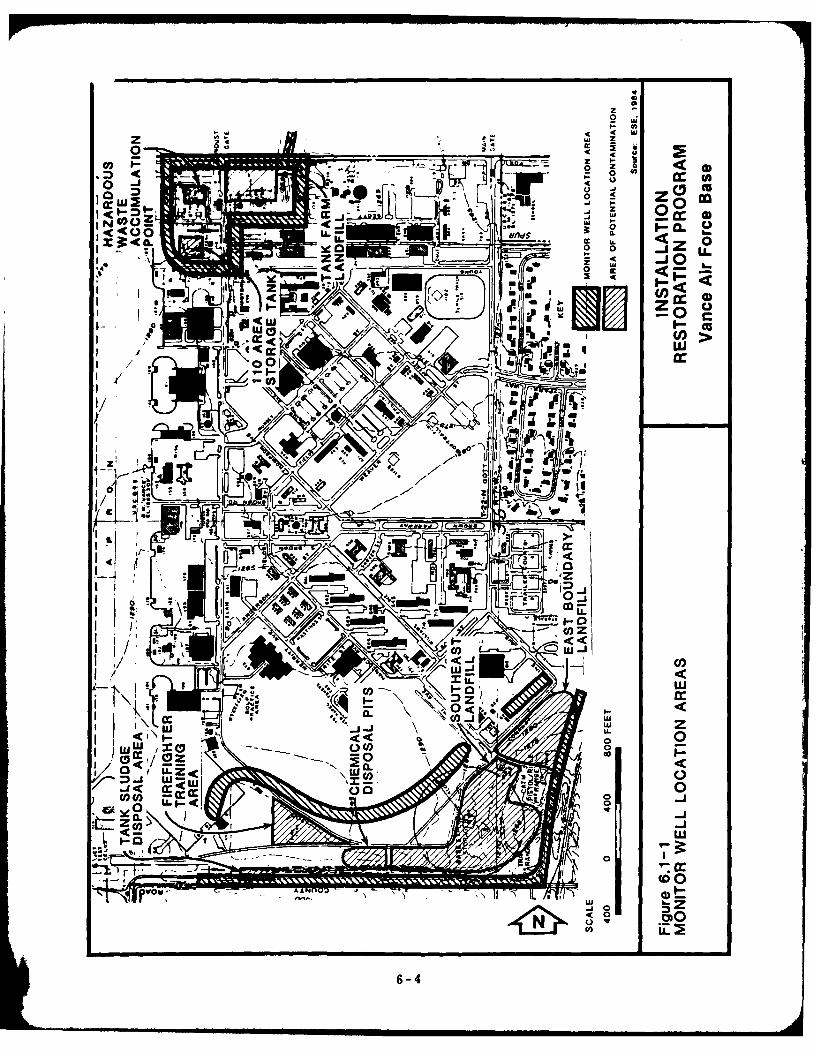
C1
z o
<400
- 0 0wleU
~ CCA
ii i
.OK\t
NIi cc_
ow'w
LU _J
CO-a
6-4r

Table 6.1-1. Summary of Recommended Monitoring for VAFB Phase IIInvestigations.
HARM Recommended RecommendedSite Score Sampling Analysis
Soutt. and East Disposal Install three wells north Total PetroleumChemical Disposal Pits 71 of disposal sites and four hydrocarbons, halo-Firefighter Training Area 56 wells between the sites genated and nonhalo-East Boundary Landfill 48 and the base boundary. genated solvents,Tank Sludge Disposal Area 47 Sample south boundary metals, PCBs,Southeast Landfill 41 drainage ditch (water and pesticides.
sediment) at east boundaryand at upstream end.Sample soil at FirefighterTraining Area and EastBoundary Landifll. Samplevegetation in East BoundaryLandfill (metals only).
Tank Farm Landfill 55 Install four wells aroundsite. Sample drainageditch (water and sediment)upstream of STP outfall.
Source, ESE, 1984.
6-5
6.2 EXISTING FACILITIES/PROCEDURES
The site visit and conversations with VAFB engineering personnel identified
several areas requiring continued attention to insure regulatory compliance
and guard against possible future contamination. The underground storage
tank at Bldg. 110 which was used to store a variety of wastes in the past
still contains an unknown amount of sludge. This sludge has not been
completely characterized. The condition and integrity of the tank are not
known. A detailed work plan should be prepared for emptying and
evaluating this tank. If evidence of leakage is found, sampling and analysis
should be undertaken to define the extent of contamination.
The ongoing effort for analysis, labeling, and off-base disposal of the
transformers currently being held should be continued to completion.
Base personnel should examine alternatives for eliminating the release of
fuels, wastewater, and fire suppressants which results from training exercises
at KAux. This could be done by upgrading the KAux facilities to the level
of those at VAFB or by transporting the KAux firefighting unit to VAFB for
training exercises.
6.3 LAND USE GUIDELINES
Careful consideration should be given to the uses made of the disposal areas
for the following reasons:
1. To provide the continued protection of human health, welfare, and
the environment;
2. To insure that the migration of potential contaminants is not
promoted through improper land uses;
3. To facilitate the compatible development of future USAF facilities;
and
4. To allow for identification of property which may be proposed for
excess or outlease.
In general, activities which would tend to disrupt the waste cells should be
avoided so as not to facilitate contaminant migration. Such activities
6-6
include foundation and drainage ditch construction. To avoid trapping any
volatile compounds that may be released from the disposal areas, structures
should not be placed over the sites.
6-7

BIBLIOGRAPHY
Adkins, W.L. and Sheldon, M.G.. 1963. Well Sample Descriptions,Anadarko Basin. Guide Book XIII. Oklahoma Geological Survey,Norman, Oklahoma.
Air Force Engineering and Services Center (AFESC). 1982. InstallationRestoration Program Management Guidance. Headquarters Air ForceEngineering and Services Center, Directorate of EnvironmentalPlanning, Tyndall Air Force Base, Florida.
Bingham, R.H. and Bergman, D.L. 1980. Reconnaissance of the WaterResources of the Enid Quadrangle, North-Central Oklahoma. HydrologicAtlas 7. Oklahoma Geological Survey, Norman, Oklahoma.
Caylor, J.H. 1957. Subsurface Geology of Western Garfield County,Oklahoma. Thesis Submitted to Graduate Faculty, The University ofOklahoma, Norman, Oklahoma.
Johnson, K.S. 1982. Guidebook for Geologic Field Trips in Oklahoma.Book fl: Northwest Oklahoma. Educational Publication 3. OklahomaGeological Survey, Norman, Oklahoma.
Johnson, K.S., et. al. 1979. Geology and Earth Resources of Oklahoma.An Atlas of Maps and Cross Sections.
MacLachlan, M.E. n.d. The Anadarko Basin (Of Parts of Oklahoma, Texas,Kansas, and Colorado). United States Department of the Interior,Geological Survey.
Morton, R.B. 1980. Reconnaissance of the Water Resources of theWoodward Quadrangle, Northwestern Oklahoma. Hydrologic Atlas 8.Oklahoma Geological Survey, Norman, Oklahoma.
Naff, J.D. 1981. Guidebook for Geologic Field Trips in North-CentralOklahoma. Educational Publication 4. Oklahoma Geological Survey,Norman, Oklahoma.
U.S. Department of Commerce (USDC). 1979. Climatic Atlas of the UnitedStates. National Climatic Center, Ashville, North Carolina.
U.S. Soil Conservation Service (USSCS). 1975. Soil Survey of AlfalfaCounty, Oklahoma.
U.S. Soil Conservation Service (USSCS). 1967. Soil Survey of GarfieldCounty, Oklahoma.
Vance Air Force Base (VAFB), 71st Flying Training Wing. 1976. Tab A-1,Environmental Narrative, Enid, Oklahoma.
Vance Air Force Base. 1982. Master Plan, Soils Plan, Civil EngineeringDivision, Enid, Oklahoma.
APPENDIX A
GLOSSARY OF TERMINOLOGY, ABBREVIATIONS, AND ACRONYMS

APPENDIX AGLOSSARY OF TERMINOLOGY, ABBREVIATIONS, AND ACRONYMS
(Page I of 6)
AFESC Air Force Engineering and Service Center
AGE Aerospace Ground Equipment
Aquifer A geologic formation, group of formations, orpart of a formation capable of yielding water toa well or spring
Aquiclude Geologic unit which impedes ground water flow
ATC Air Training Command
BES Bioenviron mental Engineering Services
Carbon tetrachloride A solvent commonly in use until the 1960s; asuspected human carcinogen
Cadmium A metal used in batteries and other industrialapplications; highly toxic to humans and aquaticlife
CERCLA Comprehensive Environmental Response,
Compensation, and Liability Act
CD Contract/DPDO Disposal
CDP Chemical Disposal Pits
CFR Code of Federal Regulations
Contaminated fuel Fuel which does not meet specifications forrecovery or recycle
Contamination Degradation of natural water quality to theextent that its usefulness is impaired; degree ofpermissible contamination depends on intended useof water
Chromium A metal used in plating, cleaning, and otherindustrial applications; highly toxic to aquatic lifeat low concentrations, toxic to humans at higherlevels
DEQPPM Defense Environmental Quality Program PolicyMemorandum
A-1

APPENDIX AGLOSSARY OF TERMINOLOGY, ABBREVIATIONS, AND ACRONYMS
(Page 2 of 6)
DIS Defense Investigative Service
Disposal of Discharge, drposit, injection, dumping, spilling, orhazardous waste placing of any hazardous waste into or on land
or water so that such waste or any constituentthereof may enter the environment, be emittedinto the air, or be discharged into any waters,including ground water
DOD Department of Defense
Downgradient In the direction of decreasing hydraulic statichead; the direction in which ground water flows
npnn Defense Property Disposal Office
Effluent Liquid waste discharged in its natural state orpartially or completely treated from amanufacturing or treatment process
EPA U.S. Environmental Protection Agency
ESE Environmental Science and Engineering, Inc.
OF Degrees Farenheit
ft feet
gal gallon
gal/yr gallons per year
gpd gallons per day
gpm gallons per minute
Ground water Water beneath the land surface in the saturatedzone that is under atmospheric or artesianpressure
HARM Hazard Assessment Rating Methodology
A-2
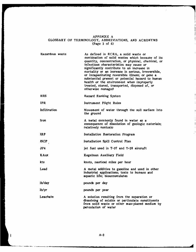
APPENDIX AGLOSSARY OF TERMINOLOGY, ABBREVIATIONS, AND ACRONYMS
(Page 3 of 6)
Hazardous waste As defined in RCRA, a solid waste orcombination of solid wastes which because of itsquantity, concentration, or physical, chemical, orinfectious characteristics may cause orsignificantly contribute to an increase inmortality or an increase in serious, irreversible,or incapacitating reversible illness; or pose asubstantial present or potential hazard to humanhealth or the environment when improperlytreated, stored, transported, disposed of, orotherwise managed
HRS Hazard Ranking System
IFR Instrument Flight Rules
Infiltration Movement of water through the soil surface intothe ground
Iron A metal commonly found in water as aconsequence of dissolution of geologic materials;relatively nontoxic
IRP Installation Restoration Program
ISCP Installation Spill Control Plan
JP4 jet fuel used in T-37 and T-38 aircraft
KAux Kegelman Auxiliary Field
kts knots, nautical miles per hour
Lead A metal additive to gasoline and used in otherindustrial applications; toxic to humans andaquatic life; bioaccumulates
lb/day pounds per day
Ib/yr pounds per year
Leachate A solution resulting from the separation ordissolving of soluble or particulate constituentsfrom solid waste or other man-placed medium bypercolation of water
A-3
APPENDIX AGLOSSARY OF TERMINOLOGY, ABBREVIATIONS, AND ACRONYMS
(Page 4 of 6)
Liner A continuous layer of natural or man-madematerials beneath or on the sides of a surfaceimpoundment, landfill, or landfill cell whichrestricts the downward or lateral escape ofhazardous waste, hazardous waste constituents, orleachate
MEK methyl ethyl ketone, a solvent used in paintthinner, stripper, and a wide variety of industrialapplications; suspected to be toxic to humans athigh levels; potentially toxic to aquatic life
mg/l milligrams per liter
MIBK methyl isobutyl ketone, a solvent used in paintstripper, thinner, and a wide variety of industrialapplications; suspected to be toxic to humans athigh levels; potentially toxic to aquatic life
MOGAS motor vehicle gasoline
mph miles per hour
NA not applicable
NCO Noncommissioned Officer
ND no data
n.d. not dated
NDI Nondestructive Inspection
Nickel A metal used in batteries, plating, and otherindustrial applications; highly toxic to humans andaquatic life
NIPDWR National Interim Primary Drinking Water
Regulations
NPDES National Pollutant Discharge Elimination System
OIC Officer-in-Charge
PCB Polychlorinated biphenyl-liquid used as adielectric in electrical equipment; suspectedhuman carcinogen; bioaccumulates in the foodchain and causes toxicity to higher trophic levels
A-4
APPENDIX AGLOSSARY OF TERMINOLOGY, ABBREVIATIONS, AND ACRONYMS
(Page 5 of 6)
PD-680 Petroleum-based cleaning solvent
Percolation Movement of moisture by gravity or hydrostaticpressure through interstices of unsaturated rockor soil
Permeability The capacity of a porous rock, soil, or sedimenttransmitting a fluid without damage to thestructure of the medium
pH Negative logarithm of hyd .. " .
an expression of acidity or alkalinity
PMEL Precision Measurement Equipment Lab
POL petroleum, oils, and lubricants
PVC polyvinyl chloride
RCRA Resource Conservation and Recovery Act
Recharge Addition of water to the ground water system bynatural or artificial processes
Silver A metal used in photographic emulsions and otherindustrial operations; toxic to humans and aquaticlife at low concentrations
SOAP Spectrographic Oil Analysis Program
SPCC Spill Prevention Control and Countermeasure(Plan)
Spill An unplanned release or discharge of a hazardouswaste onto or into air, land, or water
SS Sanitary Sewer
STP sewage treatment plant
TCE trichloroethylene, a commonly used degreasingsolvent; toxic to aquatic life and a suspectedhuman carcinogen
A-5

APPENDIX AGLOSSARY OF TERMINOLOGY, ABBREVIATIONS, AND ACRONYMS
(Page 6 of 6)
Upgradient In the direction of increasing hydraulic statichead; the direction opposite to the prevailingflow of ground water
USAF U.S. Air Force
USAFETAC U.S. Air Force Environmental Tech ApplicationsCenter
USGS U.S. Geological Survey
USSCS U.S. Soil Conservation Service
VAFB Vance Air Force Base
Water table Surface of a body of unconfined ground water atwhich the pressure is equal to that of theatmosphere
Zinc A metal with a wide variety of industrialapplications, particularly corrosion-resistant;highly toxic to aquatic life, slightly toxic tohumans at high dose levels
A-6
APPENDIX B
TEAM MEMBER BIOGRAPHICAL DATA
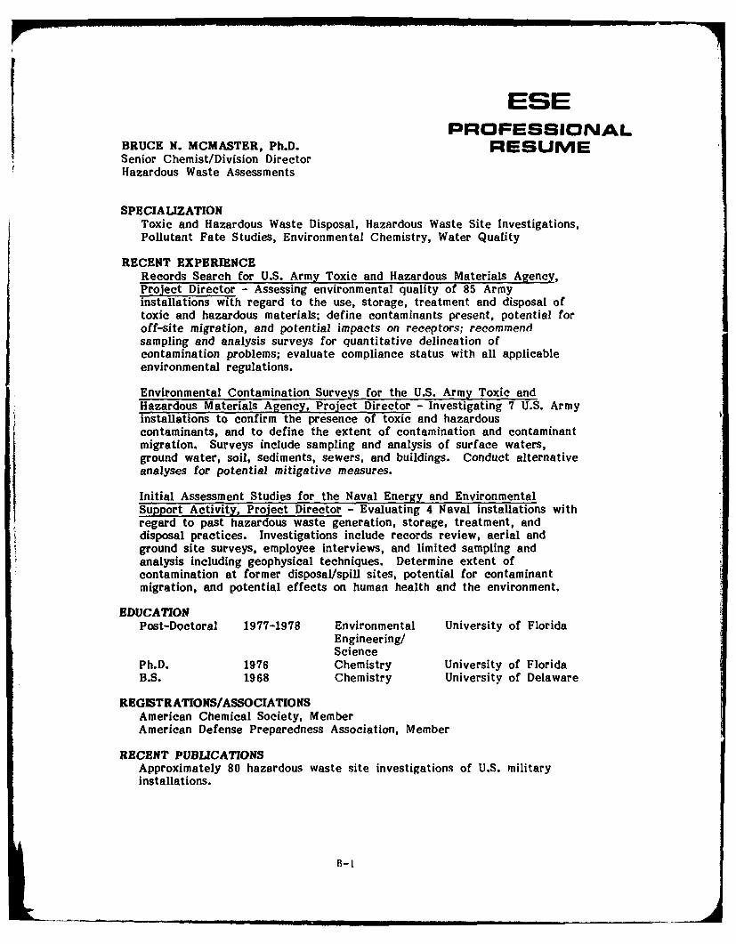
ESEPROFESSIONAL
BRUCE N. MCMASTER, Ph.D. RESUMESenior Chemist/Division DirectorHazardous Waste Assessments
SPECIALIZATIONToxic and Hazardous Waste Disposal, Hazardous Waste Site Investigations,Pollutant Fate Studies, Environmental Chemistry, Water Quality
RECENT EXPERIENCERecords Search for U.S. Army Toxic and Hazardous Materials Agency,Project Director - Assessing environmental quality of 85 Armyinstallations with regard to the use, storage, treatment and disposal oftoxic and hazardous materials; define contaminants present, potential foroff-site migration, and potential impacts on receptors; recommendsampling and analysis surveys for quantitative delineation ofcontamination problems; evaluate compliance status with all applicableenvironmental regulations.
Environmental Contamination Surveys for the U.S. Army Toxic andHazardous Materials Agency, Project Director - Investigating 7 U.S. Armyinstallations to confirm the presence of toxic and hazardouscontaminants, and to define the extent of contamination and contaminantmigration. Surveys include sampling and analysis of surface waters,ground water, soil, sediments, sewers, and buildings. Conduct alternativeanalyses for potential mitigative measures.
Initial Assessment Studies for the Naval Energy and EnvironmentalSupport Activity, Project Director - Evaluating 4 Naval installations withregard to past hazardous waste generation, storage, treatment, anddisposal practices. Investigations include records review, aerial andground site surveys, employee interviews, and limited sampling andanalysis including geophysical techniques. Determine extent ofcontamination at former disposal/spill sites, potential for contaminantmigration, and potential effects on human health and the environment.
EDUCATIONPost-Doctoral 1977-1978 Environmental University of Florida
Engineering/Science
Ph.D. 1976 Chemistry University of FloridaB.S. 1968 Chemistry University of Delaware
REGISTRATIONS/ASSOCIATIONSAmerican Chemical Society, MemberAmerican Defense Preparedness Association, Member
RECENT PUBLICATIONSApproximately 80 hazardous waste site investigations of U.S. militaryinstallations.
B-I

ESEPROFESSIONAL
JACKSON B. SOSEBEE, JR., M.S. RESUMESenior Scientist
SPECIALIZATIONHazardous Waste Studies, Environmental Chemistry, MathematicalModeling, Pollutant Fate Studies
RECENT EXPERIENCEUSAF Installation Assessment, Team Leader - Assessment of present andhistorical waste disposal activities at Vance Air Force Base, Oklahoma.
Rocky Mountain Arsenal Monitoring Plan, Task Manager - Preparingcomprehensive monitoring plan to assess extent of off-post contaminationat RMA, Colorado. Program includes ground water, surface water,sediment, potable water, air quality, and biota.
Cordova Chemical Site, Project Manager - Remedial investigation/feasibility study of hazardous waste disposal site in Michigan.
USATHAMA Navajo and Wingate Depot Activities, Project Manager -
Environmental studies of U.S. Army installations in New Mexico andArizona to determine if toxic or hazardous materials are migratingbeyond installation boundaries by surface or subsurface routes or if thepotential for such migration exists. Project included installation ofmonitor wells, collection of environmental samples, laboratory analysis forchemical contaminants, and presentation of findings.
USATHAMA, Ft. Gillem, Project Manager - Assessment of ground waterand surface water contamination resulting from landfills containinghazardous materials.
Environmental Protection Agency (EPA) Pollutant Fate, Project Director -
Assessments of the environmental fate and effects of chemicals listed bythe Interagency Testing Committee as potential hazards.
USATHAMA, Installation Assessments, Project Scientist - Conductedassessments of surface water, ground water, and air quality at militaryinstallations throughout the U.S., including Ft. Carson, Colorado.Evaluated the impact of landfill leachate on ground water quality.
EDUCATIONM.S. 1974 Environmental Studies University of MontanaB.S. 1969 Chemistry Texas Tech University
AFFILIATIONSAmerican Chemical Society (ACS)American Society for Testing and Materials (ASTM)Society for Environmental Toxicology and ChemistryColorado Ground Water Association
PUBLICATIONSTen technical publications and presentations in areas of hazardous waste,environmental chemistry, quality control, computer applications,mathematical modeling.
B-2
ESEPROFESSIONAL
WILLIAM G. FRASER, B.S., P.E. RESUMESenior Associate Engineer
SPECIALIZATIONWater Quality/Resources Engineering, Environmental Impact Assessment,Groundwater Hydrology, Siting and Environmental Studies
RECENT EXPERIENCEUSAF Installation Assessment - Currently evaluating present andhistorical waste disposal practices at Vance Air Force Base, Oklahoma.
Navy Installation Assessments - Worked as the Environmental Engineer ona project team examining historical waste handling practices and disposalsites at several Naval Bases. Studied waste types and quantities, andassessed disposal site suitability based on hydrogeologic characteristics,neighboring land use, and contaminant migration potential.
Siting Studies - Worked as staff member performing hydrologic, waterquality and air quality studies related to siting and licensing of majormining and power facilities.
Field Investigations - Streamflow measurement, water sampling, dam siteinvestigations, and groundwater testing at numerous sites in Colorado andthe West.
USATHAMA Installation Assessments - Worked as the EnvironmentalEngineer on a project team examining waste disposal practices at severalArmy Bases, including Ft. Carson, Colorado. Examined various industrialoperations and an industrial waste treatment plant handling oilywastewater.
USATHAMA Environmental Survey - Evaluated the nature and extent ofcontaminant migration from abandoned landfill sites containing solvents,POL, pesticides, and medical supplies. Reviewed surface andgroundwater analytical data and calculated pollutant mass influx atinstallation boundary based on surface runoff and groundwater flow.
EDUCATIONB.S. 1975 Civil/Environmental University of Connecticut
Engineering
REGISTRATIONRegistered Professional Engineer, State of Colorado, 1983
ASSOCIATIONSAmerican Society of Civil EngineersAmerican Water Resources Association
B-3

ESEPROFESSIONAL
KEITH C. GOVRO, M.S. RESUMEGroup Leader, Ecology
SPECIAUZATIONEcosystem Impacts from Hazardous Waste Disposal Practices, WildlifeBiology, Fisheries Biology, Water Quality
RECENT EXPERIENCEAssessment of Hazardous Waste Management/Disposal Practices atU.S. Army Installations, Team Scientist - Performed on-site inspectionswith regard to the presence of toxic and hazardous materials, thepotential for off-site migration of contaminants, and both on-site and off-site waste disposal practices. Evaluations based on review of existingdata bases, records and site surveys. Findings used to determine thenecessity for confirmatory sampling/analysis and decontaminationactivities.
Delineation of Habitat Types through Aerial Photo Interpretation, St. PaulDistrict,. Corp of Eniees PL0]f-t R,1nge. - Wnl.---~ ha.h;...t typesa,SoL t, .lJ 0 U dIgC fO CUr s UJ ... t- --V.I .. ....... .... . .*.At* *J .t,,.
within a 20,000-acre section of the Kickapoo River watershed insouthwestern Wisconsin through aerial photo interpretation. Computedacreage for each habitat type by 20-foot contour interval. Resultingdata used to determine potential habitat losses associated with theconstruction of the proposed LaFarge Reservoir.
IQ-ID Contract for Ecological Services, St. Paul District, Corps ofEngineers, Project Manager - Contract involves providing aquatic andterrestrial ecological services to the St. Paul District on a work orderbasis. Past work orders have involved ecological analysis of candidatesites for dredged material placement with Pools 8 and 9 of the UpperMississippi River.
Biological Inventory of Federal Coal Reserve Area in SoutheasternOklahoma, Bureau of Land Management, Subproject Manager - Conductedfield surveys of the vegetation, wildlife and fisheries resources withinthe 372,000-acre area to provide a data base for assessment of futureimpacts from mining operations.
Aquatic Ecosystem Surveys, Midwestern Rivers and Reservoirs - Servedas Project Manager and/or Project Biologist for numerous aquatic ecologysurveys within major Midwestern drainages such as the Mississippi,Illinois, Kaskaskia, Des Moines, Missouri, Wabash and Iowa Rivers andreservoirs such as Lake Hamilton, Lake St. Louis, Lake Springfield, andNewton Lake.
Bioassay of Dredge Spoil Impacts on Aquatic Organisms, U.S. Army Corpsof Engineers, Project Scientist - Participated in static and flow-throughbioassays assessing impacts to aquatic organisms from exposure to dredgespoils.
EDUCATIONM.S. 1977 Fisheries Biology Iowa State UniversityB.S. 1975 Wildlife and Fisheries Iowa Stat University
Biology
B-4

I APPENDIX CLIST OF INTERVIEWEES AND OUTSIDE CONTACTS
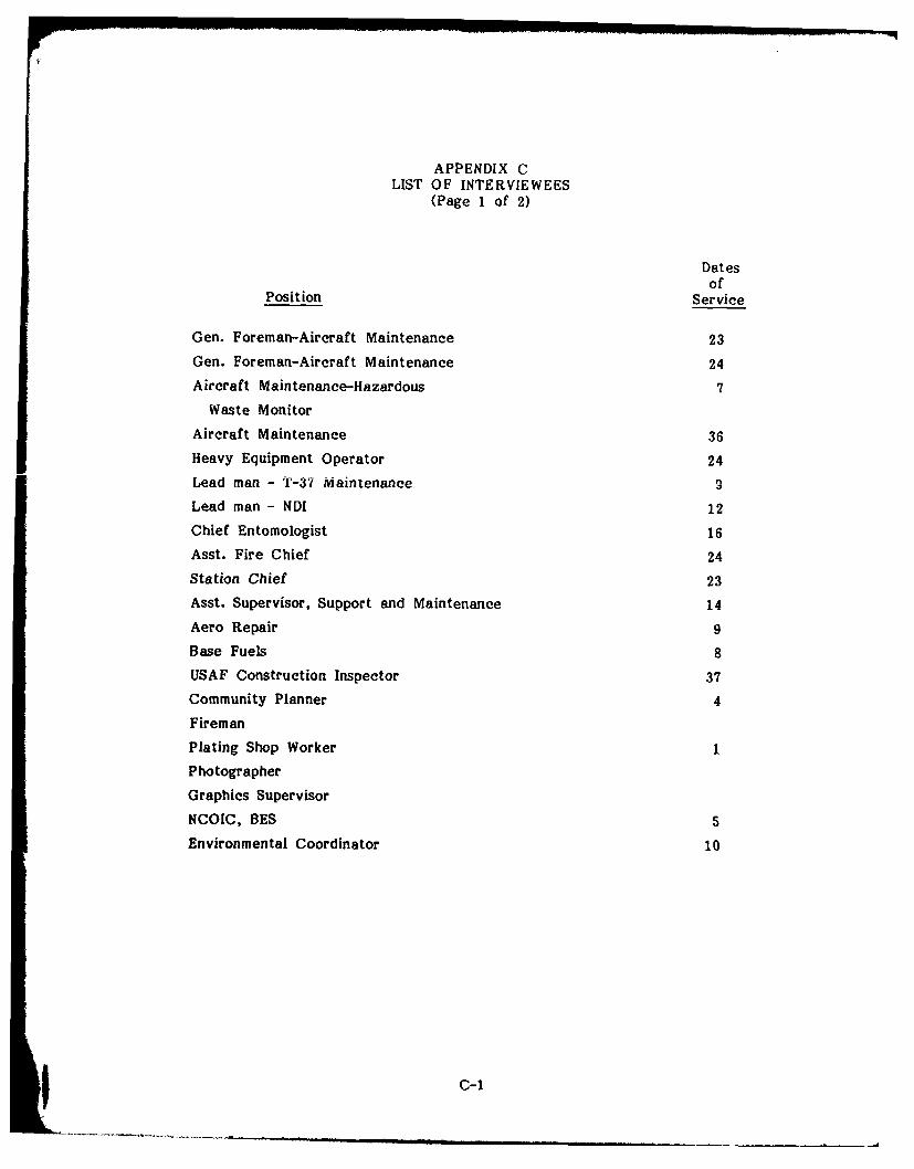
...... rq
APPENDIX CLIST OF INTERVIEWEES
(Page 1 of 2)
Datesof
Position Service
Gen. Foreman-Aircraft Maintenance 23
Gen. Foreman-Aircraft Maintenance 24
Aircraft Maintenance-Hazardous 7
Waste Monitor
Aircraft Maintenance 36
Heavy Equipment Operator 24
Lead man - T-37 Maintenance S
Lead man - NDI 12
Chief Entomologist 16
Asst. Fire Chief 24
Station Chief 23
Asst. Supervisor, Support and Maintenance 14
Aero Repair 9Base Fuels 8
USAF Construction Inspector 37
Community Planner 4
Fireman
Plating Shop Worker 1
Photographer
Graphics Supervisor
NCOIC, BES 5
Environmental Coordinator 10
C-1

APPENDIX CLIST OF OUTSIDE CONTACTS
(Page 2 of 2)
Frank Hromas, Assistant Utility SupervisorCity of WaukomisWaukomis, Oklahoma405-758-1146
Raymond Brittain, Utility DirectorCity of EnidEnid, Oklahoma405-234-0400
Oklahoma Geological SurveyNorman, Oklahoma405-325-3031
University of Okiaho,-r-a LibraryNorman, Oklahoma405-325-4142
Phillips University LibraryEnid, Oklahoma405-237-4444
Dannie Spiser, Grouaid Water GeologistOklahoma Water Resources BoardOklahoma City, Oklahoma405-271-2572
U.S. Geological Survey LibraryDenver, Colorado303-234-4133
Gary Collins, Environmental Health SupervisorGarfield County Health DepartmentEnid, Oklahoma405-233-0650
C-2
AD-A4 S01 INSTALLATION RESTO080ION PROGRAM PHASE IRECORDS SEARCH )/2A5 VANCE AIR FORCE BASE OK CHOMA U ENSIRONMENTAL SCIENCE
EDAND ENGINEERING INC DENSER CO JUL 84 F08637 83-G000UNLSSFE EEEE 13/2 EEmofllflffloflmo..f
lommomommom084
%[II
I2.
11111 1111123 0
uhII ___ IIIII1.25 '- 16
MICROCOPY RESOLUTION TEST CHARTNATIONAL BUREAU OF STANDARDS 9065 A

APPENDIX D
MASTER LIST OF SHOPS AND LABS

4.1 -. U)W,) U)L.t
00 (o-U U)
0~ U)0. 0.L.I
-0 F. (D
4) V) zUU) bo1* 4)CL
V)1
o~C ca EUV wLC
0 CO .E > 0E - 4-
*d 0 0 ~~~~~~1 0 0 t)0
ClE 4) cc 0 040 0 =0 >%. 4
cnE ~~e U)C~ U)-
U))
0 -l
E-0000 0 IV E w
ca 4
00E- W 4 040 4 C
C)
QL4 0
UC)W =00
0 cc Go Go o CI0 aa - - 4 - 4
00@Od c
01 49ad 4 0 I
D-1
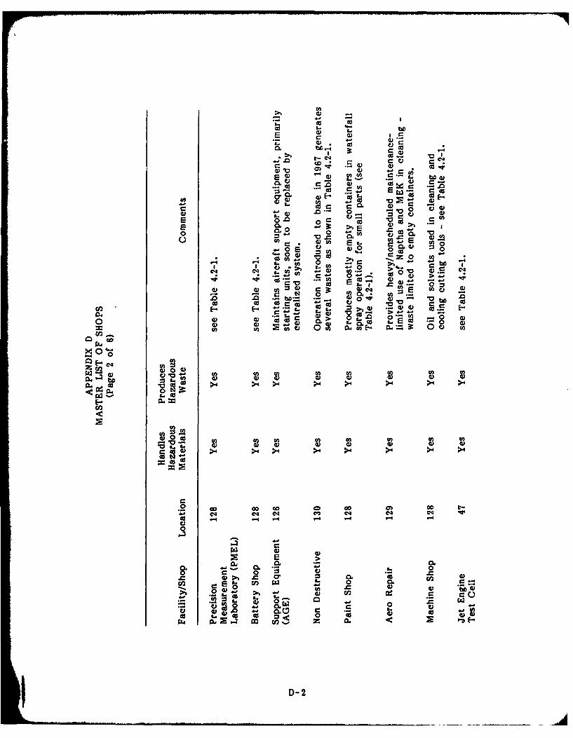
-f - - c
0 0E CL
10 =3 V )
CL U-0 C LC0 0~ E
z 03
- L- bD
-0 >) 4E 0 n 00 E 00
0 o 0 , 0d '0 b, 0
cn~4 -- 4-'14)
0* M 0) 4
0 0 W bcn -~~'- a - .44
E- ca3 fl 04
Z Oo 0o 4.. 4
"0
00
0 0dU lU )U
04 0V0 e.4 >4> >4 >4 >4 >4
4 -4
Cl):
000
~00
Cl
444 I4 04 04 4, 040 0
0 .- ~ 4 .4 .D-2
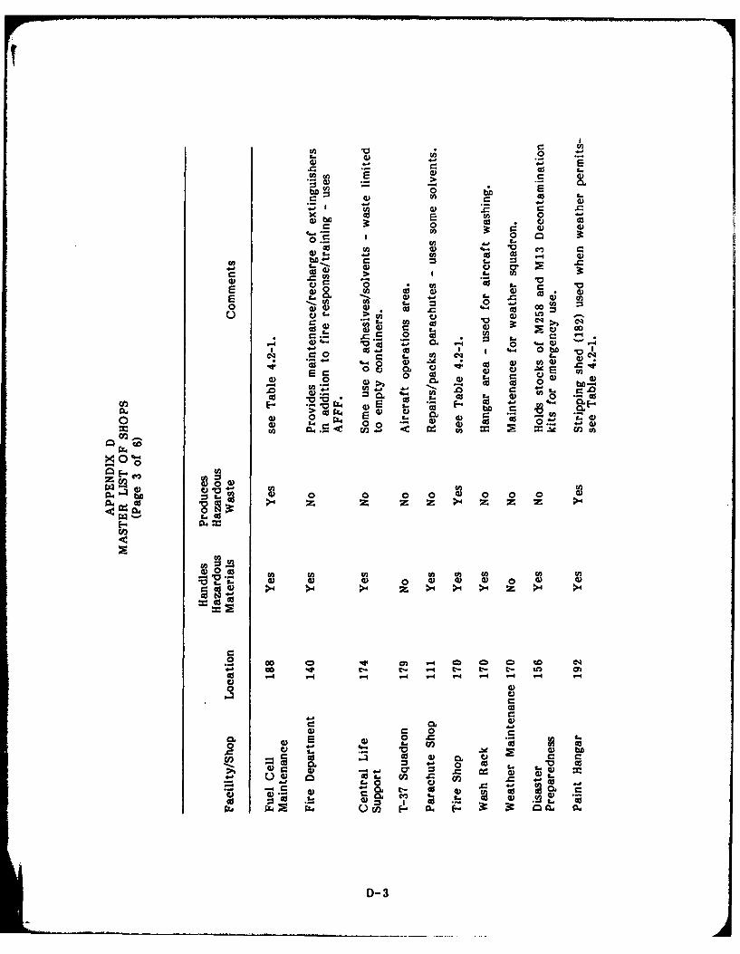
0
xO 0 0
0. 0
CD 0 as wbo t- 0 4
U) C
E U) 0 3oL t- U)0 -
U)q C .40 0
r_ 00400if C *0 . 0 UO
U) 0) 04
o 0 -e0
EC 0 0 go V2a) CL 04L
0c r= 4 0 a00 0 0. Im
C. o, 0 0 0
0 0~ 0 0-
0
CL4 W0 0 0 0 0 0000 0
0>4 z z z z >4 Z Z z >4
0 0 0 0 0 0 0 0CO > > 4 z >4 >4 >4 z >4 >4
. G o eD W c - cm e ) e 4~4- o -- t- -4 t- t- to l
-4 "4 -4- -4 -4 1
CL0_ 0
CCL) C40
Vo C k
U. CIO in0A
4D-3

f-
odv2
0a) 0 0
0 C0
'.-. V 0
co IV ..
0 0n Eo C E-~ 0
0 U) 0 &0 4) 4 ) cc 0)0 c
0 0 0) 0
-o ,l) wa)
Co 02 0 bf0- 0
0 p o 0-V)0~-f 1bA 02 >4 z >4 z
04 02 Cox.O
~r0 0)0 020
>4 z4 >4 z > z z z
00200f0
02CL0 0 00 0a) a 0 a) a )
.L in c2 r-q'A
0 C ooC
Cn
t- GO Cow
D-4
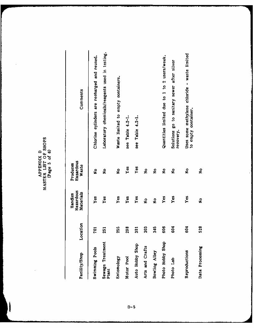
M 4)
ca 4)
0k co 0
00 L.
L) as E4) o) 0 0
EE 0 0I I.
0 E 0.0
0 E
0) 0 2) W~4) W I 4 -~
* 0 2
0 0 &. &0 U)0~
04)
0 - S : t. 4)4 w 4 w w 0 00
0 4 0 l 0 0 m) 4) 0 0 0 0
00
~00
.2i c Ei c in cn ul c0- 0 wn i ~ 0 e
0 o E- bo eq eq D ~ c c c c
4- 1 0 a0. 0
4) 0 0
EO bfl : o 0 0~ to 41 .0 .C4-
# 0 j 2 0 o 0 0.43 4- - 0 0.w04 rn co 0 a4 a ~ . 0
D-5

4)0
0
EU U
o
0 0
U) 0) .0 .
0 000-~
0a.ad 0 g S. 2 0 0 0
a4 0d 00 cd > 4 >
Z4o
U)
ma04 0 0 0 0w >4 z z >4 >4
6~0Coo
U)U
0000 00 0 E0 0
0 UU 4 l)i
D-6~

APPENDIX E
PHOTOGRAPHS OF DISPOSAL/SPILL SITES

FIREFIGHTER TRAINING AREA AND SLUDGE DISPOSAL AREA
SOUTtcgW LA4M
AREAS OF POTENTIAL IINSTALLATIONCONTAMINATION I RESTORATION PROGRAM
Vance Air Force Base
E-1
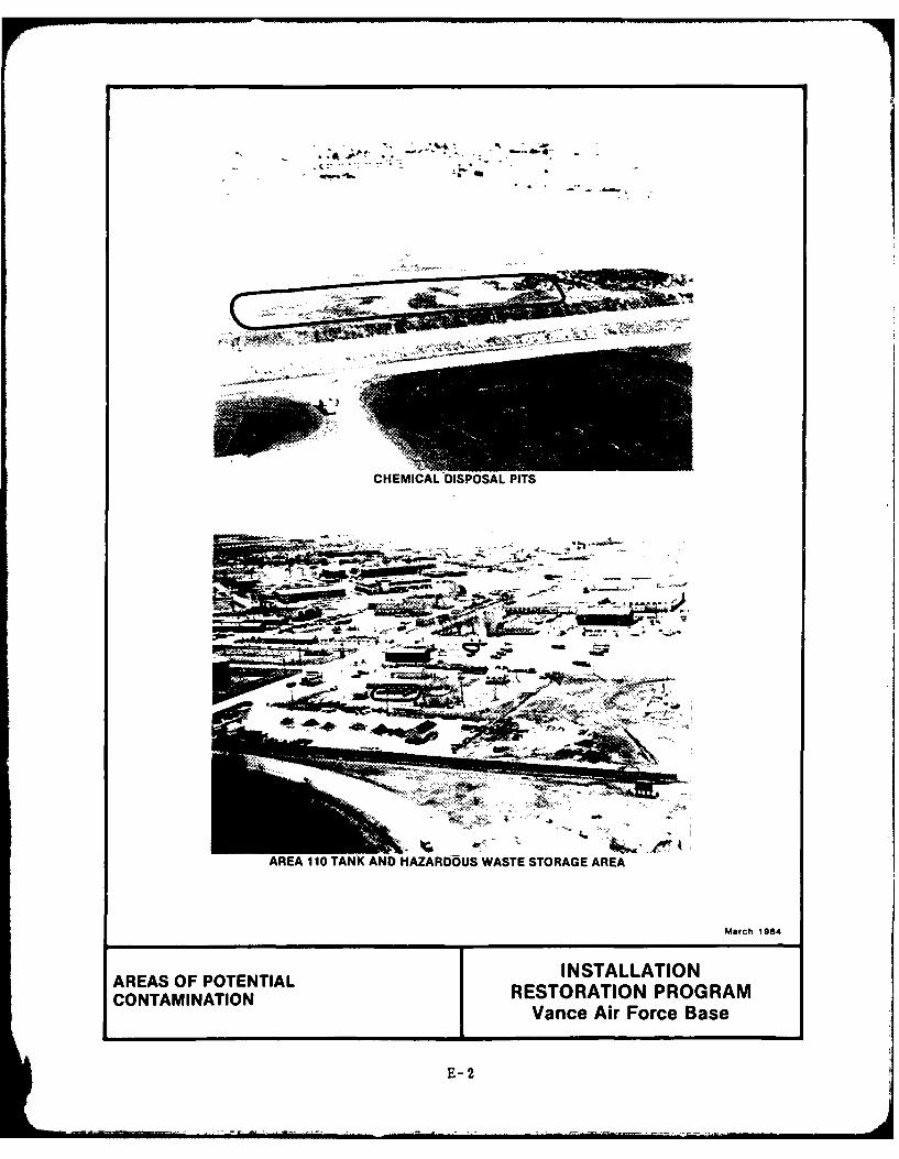
Jk2%:.;A
CHEMICAL DISPOSAL PITS
A -
AREA 110 TANIK AND HAZARDOUS WASTE STORAGE AREA
March 1984
AREA OF OTENIALINSTALLATIONCONTMINAIONRESTORATION PROGRAM
Vance Air Force Base
E-2
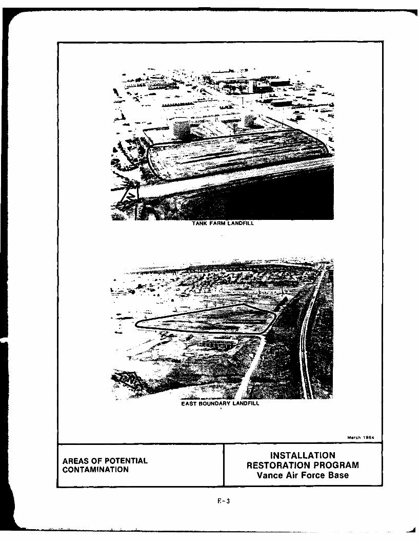
.7
EAST BOUNDARY LANDFILL
March 1984
AREAS OF POTENTIAL INSTALLATIONCONTAMINATION RESTORATION PROGRAM
Vance Air Force Base
E-3
APPENDIX F
USAF IRP HAZARD ASSESSMENT RATING METHODOLOGY
USAF INSTALLATION RESTORATION PROGRAM
HAZARD ASSESSMENT RATING METHODOLOGY
BACKGROUND
The Department of Defense (DOD) has established a comprehensive
program to identify, evaluate, and control problems associated with past
disposal practices at DOD facilities. One of the actions required under
this program is to:
"develop and maintain a priority listing of con-
taminated installations and facilities for remedialaction based on potential hazard to public health,welfare, and environmental impacts." (Reference:DEQPPM 81-5, 11 December 1981).
Accordingly, the United States Air Force (USAF) has sought to establish
a system to set priorities for taking further actions at sites based
upon information gathered during the Records Search phase of its
Installation Restoration Program (IRP).
The first site rating model was developed in June 1981 at a meeting
with representatives from USAF Occupational Environmental Health
Laboratory (OEHL), Air Force Engineering Services Center (AFESC),
Engineering-Science (ES) and CH2M Hill. The basis for this model was a
system developed for EPA by JAB Associates of McLean, Virginia. The JIM
model was modified to meet Air Force needs.
After using this model for 6 months at over 20 Air Force installa-
tions, certain inadequacies became apparent. Therefore, on January 26
and 27, 1982, representatives of USAF OEEL, AFESC, various major com-
mands, Engineering Science, and C82 M Hill met to address the inade-
quacies. The result of the meeting was a new site rating model designed
to present a better picture of the hazards posed by sites at Air Force
installations. The new rating model described in this presentation is
referred to as the Hazard Assessment Rating Methodology.
F-I
- .. . . . --.. . . .. . . . . . .... .. . .. ... .. ... .... ..... ... ... .. .. . . d
PURPOSE
The purpose of the site rating model is to provide a relative
ranking of sites of suspected contamination from hazardous substances.
This model will assist the Air Force in setting priorities for follow-on
site investigations and confirmation work under Phase II of IRP.
This rating system is used only after it has been determined that
(1) potential for contamination exists (hazardous wastes present in
sufficient quantity), and (2) potential for migration exists. A site
can be deleted from consideration for rating on either basis.
DESCRIPTION CI MODEL
Like the other hazardous waste site ranking models, the U.S. Air
Force's site rating model uses a scoring system to rank sites for
priority attention. However, in developing this model, the designers
incorporated some special features to meet specific DOD program needs.
The model uses data readily obtained during the Record Search
portion (Phase I) of' the IMP. Scoring judgments and computations are
easily made. In assessing the hazards at a given site, the model
develops a score based on the most likely routes of contamination and
the worst hazards at the site. Sites are given low scores only if there
are clearly no hazards at the site. This approach meshes well with the
policy for evaluating and setting restrictions on excess DOD properties.
As with the previous model, this model considers four aspects of
the hazard posed by a specific site: the possible receptors of the
contamination, the waste and its characteristics, potential pathways for
waste contaminant migration, and any efforts to contain the contami-
nants. Each of these categories contains a number of rating factors
that are used in the overall hazard rating.
The receptors category rating is calculated by scoring each factor,
multiplying by a factor weighting constant and adding the we-ighted
scores to obtain a total category score.
F-2

The pathways category rating is based on evidence of contaminant
migration or an evaluation of the highest potential (worst case) for
contaminant migration along one of three pathways. If evidence of
contaminant migration exists, the category is given a subscore of 80 to
100 points. For indirect evidence, 80 points are assigned and for
direct evidence 100 points are assigned. If no evidence is found, the
highest score among three possible routes is used. These routes are
surface water migration, flooding, and ground-water migration. Evalua-
tion of each route involves factors associated with the particular mi-
gration route. The three pathways are evaluated and the highest score
among all four of the potential scores is used.
The waste characteristics category is scored in three steps.
First, a point rating is assigned based on an assessment of the waste
quantity and the hazard (worst case) associated with the site. The
level of confidence in the information is also factored into the as-
sessment. Next, the score is multiplied by a waste persistence factor,
which acts to reduce the score if the waste is not very persistent.
Finally, the score is further modified by the physical state of the
waste. Liquid wastes receive the maximum score, while scores for
sludges and solids are reduced.
The scores for each of the three categories are then added to-
gether and normalized to a maximum possible score of 100. Then the
waste management practice category is scored. Sites at which there is
no containment are not reduced in score. Scores for sites with limited
containment can be reduced by 5 percent. If a site is contained and
well managed, its score can be reduced by 90 percent. The final site
score is calculated by applying the waste managment practices category
factor to the sum of the scores for the other three categories.
F-3I!

FIGURE1
I a -8
ElIL 0
ull<I~ 2 zI..o
Wo 0 l Iou
wC ILCiO >-Ci r
<0cf )
a. 0.
.1 0 rLS a
15C Aw
Lu~ CwjjI-ICO 0.
5-0UA
co a
F-4 s

FIGURE 2
HAZARD ASSESSMENT RATING METHODOLOGY FORMPage I of 2
ILCAZQN
DA=' Cr OrMU.MO CK C8 RC
L RECEPTORS
Rating rector PouuibleRating r w( 0-) mltblLec Soce Scoe
A. Pog.astion vithin 1r000 feet of site 4
a. Distanco to neacet'voel. 10
C. Land uae/zoning within I 3.o redius 3C
0. otitance t teesrsias botndo cese__ _ " 5
Z. Critical enviroments within I mile radius of @ito 10
r. water aualit of neeeut surface vater body .
G. Ground vater use of u-emust asquifec ,_9
f. lopulatioo mcred by euafae water suplywithin 3 m.les downtrem of site 6
z. Population served by ground-watec supplywithin 3 11e of site •
SubotaLs
Seceptore whosre (100 X factor score subtotaL,/nLmim scoce subtotal)
IL WASTE CHARACTERISTICS
A. Select the factor- esce based an the estimated quantity, the degee of haard, end the confidence Level ofthe infotuationl.
1. Waste quantity (S - smal,, N - medim. L a La-pe)
2. Confidence level (C - confirmed, S a suspected)
3. Sanad rating (9 a high. K a medium. L a low)
factor lubecore A (frnm 20 to 100 based on factor acote matrix)
S. appLy persistence facorrector Subacore A X 1ensistane fctor Subecoce a
C. Apply IyeicaL state multipliec
Subcoce 3 X 7hysical tate VjipLUec W aste Characteristics Subscoce
F-5

FIGURE 2 (Continued)_ Page 2 of 72
IL PATHWAYSFactor NaxlmumRating ractOc Possible
Rating Factoc (0-3) ultipliea Scots Scoce
A. 19 tAece L evtdence of mtgcaeian of haxsadous contanants, astiqn akimm factor subscoce of 100 points fogdirect evidence ot 00 points fot Lndirect evidence. it direct evidence exists then proceed to C. If noevidence or indirect evidence exists, proceed to a.
Subecoce
a. Pate the ig atosn. potential 9or 3 potential pathwars surface water -*igation, flooding. and gcound-vateemiqcarion. Select the highest rating, and proceed to C.
1. Surface water migratlo
Distance to macset surface water _
Not preciptation 4
Surface erosimn _S_
Surface raeabiU _t y
Rainfall intenAetv' o
Subtetals
Subecame (100 1 fasor seo mbx-tal./maximum score subtotal)
2. plowitng I I I Ikubamoe (100 x factor mcore/3)
3. Ommd-water uigtatoa
thp to ground water€ I
Not prci~pitation 6
Subsaucfl 'owsJ
tiret aces" to ground water _
SubtataLs
Subecore (100 z factor s€tce subtotal/.axmulai scere subtotal)
C. uiqbest pathway su0ecoce.
zntee tie hiqbest subecoce value fom A, -1., D-2 cc S-3 above.
Pathways Subscoce
IV. WASTE MANAGEM T PRACTICES
A. Average the three sub ecoree for recepocs. waste characteristics, and pathway%.
Rsceptogs_____Waste Charactristics
pathw""______
Total divided by 3Gcoss Total $cote
3. Apply factor fe waste containment from waste management practices
Gross Total Sote X Waste Hamaqeaest Peactices rector m Final Score
F-6
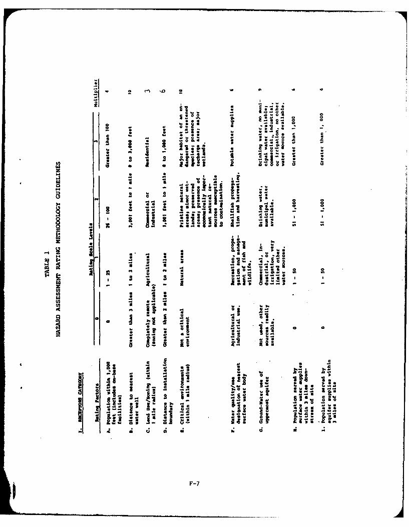
C0 a0
- I-
F4. .4 cc 0~a a L .4
a a..4 *0
a .'.a - -aa a
a0 a - 0P4 0 . - ~ .
NO 9 c nNa a 0
Ca a
31 a u b.
IS 0
a d Od a I 31 2 1 1 i
F-

S~a4j
AO' 1, *aas La.
44.4 h.44 * I
31a 04 6 .
Id4 .
to 3 jW 00 Id4 *- ~ 4
a 1 380Z*-.E ftM ;Ca.A 4 L I
C40
40 M444 toS
00 1 .0 0
04~ 0 0 12
rz~F-8
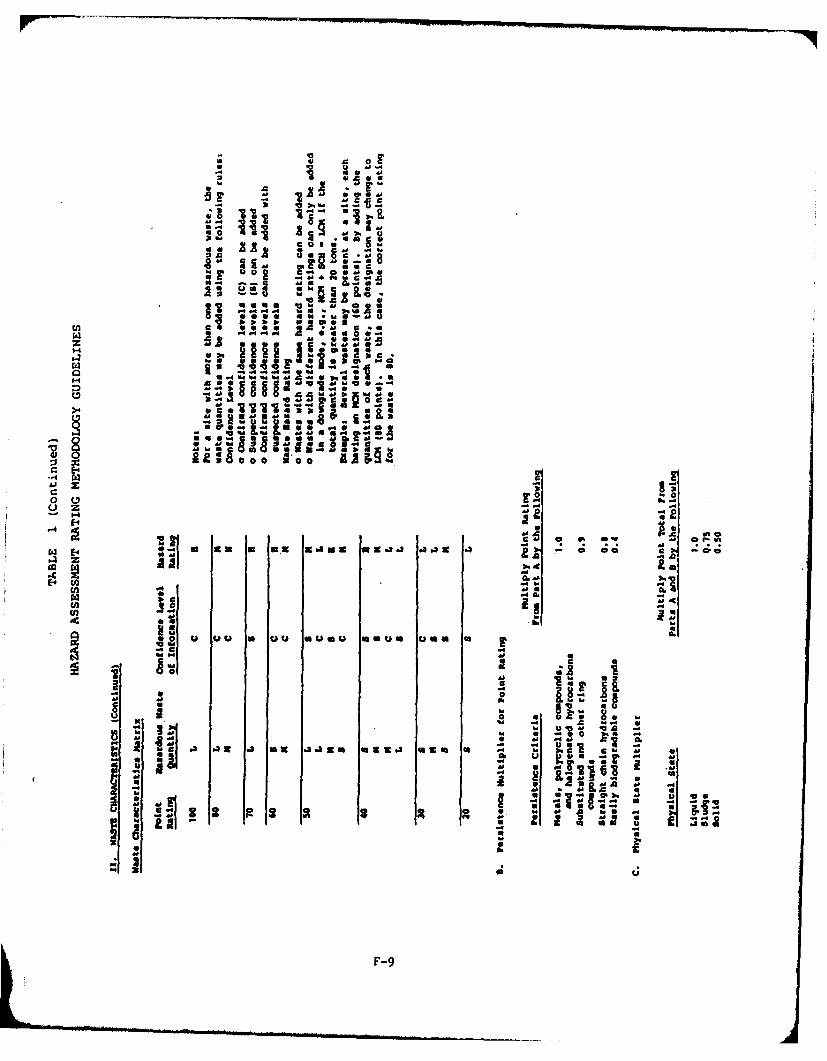
* 4 0
- aU
0 0 c
4.0 d~
It. 2 '" '
=- a. 0i 0 0E-4. -
a.-
z .e
E-4.-g~
-4~I C. c
E4 A~ .x w- K V 480 a
Sz
0U .4
Liin
A.A
104 Z l .
i~~I - - -- ~ -9* i .4J0
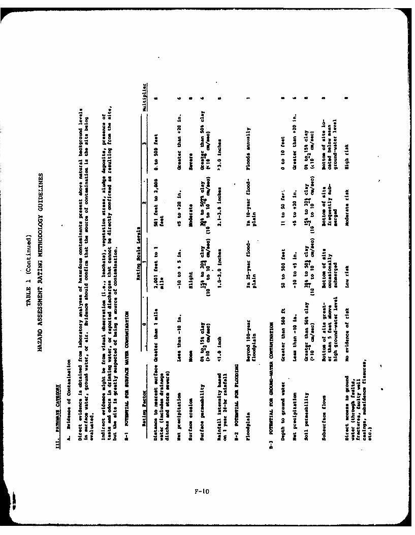
06 C 3-
Alp a 4a 1
06 4 0 6.C
" a44 . - AA ~ 6.04 Z4 a A~0 M
ra- a ~ m o -
44 f" 0 4A M+4 + c .4
Z~ ~ a 4
4.0 on 0m bAdP
a. 4! ZIP2 S 24 0 0 ~ 4.
34 a0 dP ON6U 4 0 uU44~~b a. s . . 41 . - I" M
a. a4 cS 1::: a
0 6 04
2 C MO .4A
34,
1.6 V~ 41 4
os
36 .4M
16Is 400.
60 X; US ( n Ia
0) .4 M4 M U a F0 10

a-
ti At
-A A
14 low 4
0 0'
F-11S
APPENDIX G
HAZARD ASSESSMENT RATING METHODOLOGY FORMS
I
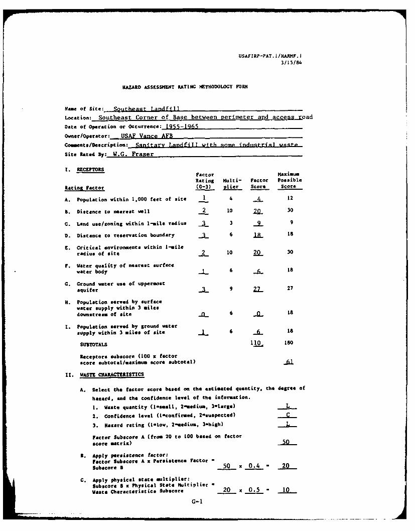
USAFIRP-PAT. I/HARNF. t
3/15/84
HAZARD ASSESSMENT RATING METHOIDOLOGY FORM
Name of Site: Southeast Landfill
Location: Southeast Corner of Base between Perimeter and access road
Date of Operation or Occurrence: 1955-1965
Owner/Operator: USAF Vance AFB
Coments/Description: Sanitary Landfill with .anmp indngtrianl was.L._
Site Rated By: W.G. Fraser
I. RECEPTORSFactor MaximumRating Multi- Factor Possible
Rating Factor (0-3) plier Score Score
A. Population within 1,000 feet of site 1 4 /1 12
B. Distance to nearest well 2 10 30
C. Land use/coning within 1-mile radius 3 3 9
D. Distance to reservation boundary _ 6 18
E. Critical environments within 1-mileradius of site 2 10 20 30
F. Water quality of nearest surfacewater body 6 18
C. Ground water use of uppermost
aquifer 9 27 27
H. Population served by surfacewater supply within 3 milesdownstream of site n 6 0 18
I. Population served by ground water
supply within 3 miles of site 6 18
SUBTOTALS 110 80
Receptors subscore (100 x factorscore subtotal/maximum score subtotal)
11. WASTE CHARACTERISTICS
A. Select the factor score based on the estimated quantity, the degree of
hazard, and the confidence level of the information.
I. Waste quantity (l-small, 2-sedium, 3-large) L
2. Confidence level (I-confirmed, 2asuspected)
3. Hazard rating (inlow, 2-medium, 3-high) L
Factor Subscore A (from 20 to 100 based on factor
score matrix)
B. Apply persistence factor:Factor Subscore A x Persistence Factor -
Subscore 5 50 x 0.4 - 20
C. Apply physical state multiplier:Subscore 8 x Physical State Multiplier -
Waste Characteristics Subscore 20 x 0.5 - 10
G-I

USAFIRP-PAT. I/HAR/F.203/15/84
HAZARD ASSESSMENT RATING METHODOLOGY FORM(Continued. Page 2 of 2)
111. PATHWAYS
A. If there is evidence of migration of hazardous contaminants, assign
maximum factor subscore of 100 points for direct evidence or 80 pointsfor indirect evidence. If direct evidence exists, proceed to C. If
no evidence or indirect evidence exists, proceed to B.
Subscore __
B. Rate the migration potential for three potential pathways: surfacewater migration, flooding, and ground water migration. Select the
highest rating and proceed to C.Factor Maximum
Rating Multi- Factor Possible
Rating Factor (0-3) plier Score Score
1. Surface water migration
Distance to nearest surface
water 8 24 24
Net precipitation 6 0 18
Surface erosion 8 24
Surface permeability 6 "__ 18Rainfall intensity .2 8 16 24
SUBTOTALS 56 108
Subscore (100 x factor score subtotal/
maximum score subtotal) 520 0 3
2. Flooding - 1 0
Subscore (100 x factor score/3)
3. Ground water migration
Depth to ground water 2 8 16 24
Net precipitation "F 6 18
Soil permeability 8 24
Subsurface flows _ 8 24
Direct access to groundwater 0 8 0 24
SUBTOTALS 24 114
Subscore (100 z factor score subtotal/
maximum score subtotal)
C. Highest pathway subecore
Enter the highest subscore value from
A, 3-1, 5-2, or 5-3 above. Pathways Subscore 52
IV. WASTE MANAGEMENT PRACTICES
A. Average the three subscores for receptors, waste characteristics, and
pathways.
Receptors 61
Waste Characteristics 0
Pathways
TOTAL 173 divided by 3 - 41 Gross total score
3. Apply factor for waste containment from waste management practices.Gross total score x waste management practices factor - final score.
41 x 1.0 - 41G-2
IA
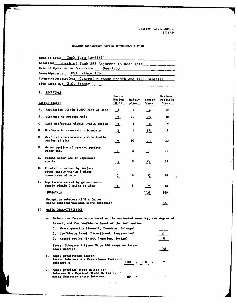
USAFIRP-PAT. I/HARF. 1
3/15/84
HAZARD ASSESSMENT RATING METHODOLOGY FORM
Name of Site: Tank Farm Landfill
Location: Nnrth of Tank 265s AdjaCent to wpt r
Date of Operation or Occurrence: 1944-1950
Owner/Operator: USAF Vance AFB
Coemnts/Description: General purpose trench and fill landfLll
Site Rated sy: W.G. Fraser
I. RECEPTORSFactor Maximum
Rating Multi- Factor PossibleRating Factor (0-3) plier Score Score
A. Population within 1,000 feet of site 1 4 4 12
S. Distance to nearest well 10 .& 30
C. Land use/zoning within 1-mile radius 3 -_9_ 9
D. Distance to reservation boundary 6 jz 18
E. Critical environments within 1-mileradius of site 10 2& 30
F. Water quality of nearest surfacewater body 6 6 18
G. Ground water use of uppermostaquifer 9 .23 27
H. Population served by surface
water supply within 3 milesdownstream of site 6 18
1. Populacion served by ground water
supply within 3 miles of site 6 18
SUSTOTALS 11L 180
Receptors subscore (100 x factor
score subtotal/maximum score subtotal)
II. WASTE CHARACTERISTICS
A. Select the factor score based on the estimated quantity, the degree of
hazard, and the confidence level of the ieforsat ion.
1. Waste quantity (-ismall. 20ediu, 3-large)
2. Confidence level (l-confirmed, 20suspected)
3. Hazard rating (1-iow, 2"wdiu., 3hish) H
Factor Subscore A (from 20 to 100 baed e fator
score matrix)
5. Apply persistence factor:Factor Subscore A u Persisteece Factor *
Subscore 1 100 , 0 -
C. Apply physical states aliptierSubscoro I a Physical Stts "mapvierwaste Characteristi cs Sboce

USAFIRP-PAT. I/HARFo203/15/84
HAZARD ASSESSMENT RATING METHODOLOGY FORM
(Continued, Page 2 of 2)
III. PATHWAYS
A. If there is evidence of migration of hazardous contaminants, assign
maximum factor subscore of 100 points for direct evidence or 80 points
for indirect evidence. If direct evidence exists, proceed to C. if
no evidence or indirect evidence exists, proceed to B.
Subscore
I. Rate the migration potential for three potential pathways: surface
water migration, flooding, and ground water migration. Select the
highest rating and proceed to C.Factor MaximumRating Multi- Factor Possible
Rating Factor (0-3) plier Score Score
1. Surface water migrationDistance to nearest surface
water 8 _ 24
Net 'recipitation 6 24 18Surfoce erosion 8 8 24
Surface permeability n 6 18
Rainfall intensity 8 624
SUBTOTALS 48 108
Subecore (100 x factor score subtotal/maximum score subtotal) .44
2. Flooding 1 3
Subscore (100 x factor score/3) 0
3. Ground water migration
Depth to ground water 8 24
Net precipitation 6 U 18
Soil permeability 8 24
Subsurface flows g 24
Direct access to ground
water 8 24
SUBTOTALS 114
Subscore (100 x factor score subtotal/
maximum score subtotal)
C. Highest pathway subscore
Enter the highest subscore value from
A, 9-1, B-2, or 5-3 above. Pathways Subscore 4
IV. WASTE HANAGEENT PRACTICES
A. Average the three subscores for receptors, waste characteristics, and
pathways.
Receptors 61
Waste Characteristics 56
Pathways
TOTAL * divided by 3 - _Gross total score
3. Apply factor for waste containment from waste management practices.
Gross total score x waste management practices factor a final score.
55 1.0 - 55 G-4
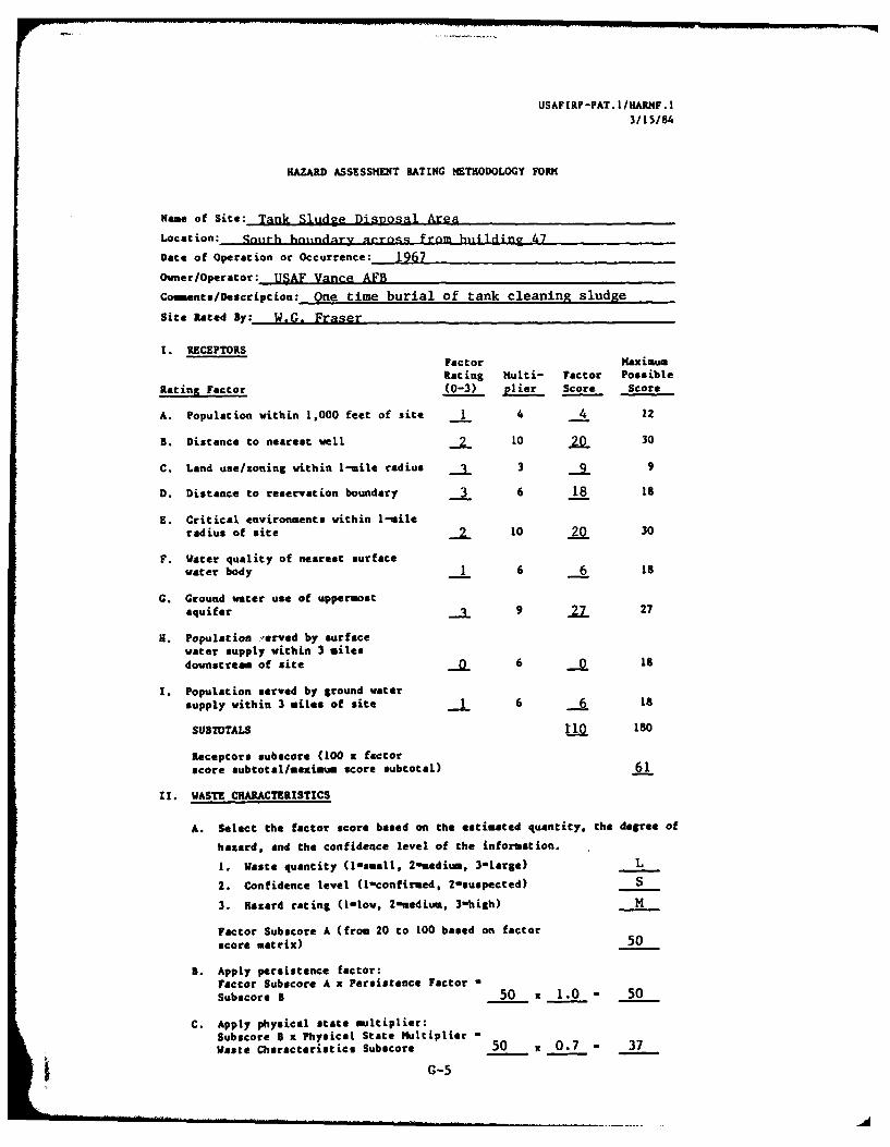
USAFIRP-PAT. I/HARMF. I
3 /15/84
HAZARD ASSESSMENT RATING METHODOLOGY FORM
Name of Site: Tank Sludge Disposal Area
Location: qouth honindary aerna-, from hiin1din? 47
Date of Operation or Occurrence: 1967
Owner/Operator: USAF Vance AFB
Coments/Description: One time burial of tank cleaning sludge
Site Rated By: W.G. Fraser
1. RECEPTORSFactor maximumRating Multi- Factor Possible
Rating Factor (0-3) plier Score Score
A. Population within 1,000 feet of site 1 4 4 12
B. Distance to nearest veil 10 30
C. Land use/zoning within 1-mile radius 3 9
D. Distance to reservation boundary 3 6 18 18
E. Critical environments within 1-mileradius of site 10 20 30
F. Water quality of nearest surfacewater body 1 6 6 18
G. Ground water use of uppermostaquifer . 9 2 27
H. Population 'erved by surfacewater supply within 3 milesdownstream of site 6 .1
I. Population served by ground watersupply within 3 miles of site 6 -6 18
SUBTOTALS 180
Receptors subscore (100 x factorscore subtotal/maximum score subtotal) 61
It. WASTE CHARACTERISTICS
A. Select the factor score based on the estimated quantity, the degree of
hazard, and the confidence level of the information.
I. Waste quantity (l-small, 2-medium, 3-Large) L
2. Confidence level (lconfirmed, 2-suspected) S
3. Hazard rating (1-low, 2-medium, 3-high) H
Factor Subscore A (from 20 to 100 based on factorscore matrix) 50
B. Apply persistence factor:Factor Subscore A x Persistence Factor aSubscore B 50 x 1.0 - 50
C. Apply physical state multiplier:Subscore 5 x Physical State Multiplier -Waste Characteristics Subscore 50 x 0.7 - 37
G-5

USAFIRP-PAT. 1/HARHF .203/15/84
HAZARD ASSESSMENT RATING METHODOLOGY FORK(Continued, Page 2 of 2)
111. PATHWAYS
A. If there is evidence of migration of hazardous contaminants, assign
maximum factor subscore of 100 points for direct evidence or 80 pointsfor indirect evidence. If direct evidence exists, proceed to C. Ifno evidence or indirect evidence exists, proceed to B.
Subscore --
B. Rate the migration potential for three potential pathways: surface
water migration, flooding, and ground water migration. Select the
highest rating and proceed to C.Factor Maxim.mRating Multi- Factor Possible
Rating Factor (0-3) plier Score Score
1. Surface water migration
Distance to nearest surfacewater 3 8 24 24
Net precipitation -T 6 18
Surface erosion -- a 24Surface permeability 6 -U 18
Rainfall intensity M 2
SUBTOTALS 48 108
Subecore (100 x factor score subtotal/maximum score subtotal) A.
2. Flooding 0 1 0 3
Subscore (100 x factor score/3) 0
3. Ground water migration
Depth to ground water 2 8 16 24
Net precipitation -U* 6 18
Soil permeability 8 24Subsurface flows -- 8 _ 24Direct access to groundwater 0 8 0 24
SUBTOTALS 24 114
Subscore (100 x factor score subtotal/
maximum score subtotal) 21
C. Highest pathway subscore
Enter the highest subscore value from
A, 3-1, 5-2, or B-3 above. Pathways Subecore 44
IV. WASTE MANAGEMENT PRACTICES
A. Average the three subscores for receptors, waste characteristics, and
pathways.
Receptors 61
Waste Characteristics 37
Pathways 44
TOTAL 1A2_ divided by 3 - 47 Gross total score
B. Apply factor for waste containment from waste management practices.Gross total score x waste management practices factor a final score.
47 x 1.0 - 47G-6

USAFIRP-PAT. 1/KARF. 1
3/15/84
HAZARD ASSESSMENT RATING METHODOLOGY FORKI
Name of Site: ri:ljn Plnt- T nA ill
Location: BEtw n Conwny Rrrf- nd tjh p a& n f4r
Date of Operation or Occurrence: 1950-1955
Owner/Operator: ITRAF Vane AFB
Coments/Description: General Durpose trench and fill Landfill
Site Rated By: W.G. Frnnar
I. RECEPTORS
Factor maximumRating Multi- Factor Possible
Rating Factor (0-3) plier Score Score
A. Population within 1,000 feet of site - 4 4 12
B. Distance to nearest well -2 10 .0 30
C. Land use/zoning vithin 1-mile radius . 3 9
D. Distance to reservation boundary 3 6 18 18
E. Critical environments vithin 1-mileradius of site 2 10 20 30
F. Water quality of nearest surfacewater body 1 6 18
G. Ground water use of uppermostaquifer 1 9 27 27
H. Population served by surfacewater supply within 3 miles
downstream of site 0 6 0 18
1. Population served by ground watersupply within 3 miles of site 6 18
SUBTOTALS 110 180
Receptors subscore (100 x factor
score subtotal/maximum score subtotal)
It. WASTE CHARACTERISTZCS
A. Select the factor score based on the estimated quantity, the degree of
hazard, and the confidence level of the information.
1. Waste quantity (lsmall. 2-medium, 3-Large) L
2. Confidence level (I-confirmed, 2-suspected) C
3. Hazard rating (Inlow, 2-medium, 3-high) h
Factor Subscore A (from 20 to 100 based on factorscore matrix)
I. Apply persistence factor:factor Subscore A x Persistence Factor -
Subscore B 50 x 0.8 - 40
C. Apply physical state multiplier:Subscore 5 x Physical State Multiplier -
Waste Characteristics Subscore 40 x 0.7 - 30
G-7

USAFIRP-PAT. I/HARMF .203/15/84
HAZARD ASSESSMENT RATING METHODOLOGY FORN(Continued. Page 2 of 2)
111. PATHWAYS
A. If there is evidence of migration of hazardous contaminants, assignmaximum factor subscore of 100 points for direct evidence or 80 pointsfor indirect evidence. If direct evidence exists, proceed to C. Ifno evidence or indirect evidence exists, proceed to B.
Subscore
B. Rate the migration potential for three potential pathways: surfacewater migration, flooding, and ground water migration. Select thehighest rating and proceed to C.
Factor MaximumRating Multi- Factor Possible
Rating Factor (0-3) plier Score Score
1. Surface water migrationDistance to nearest surfacewat er 8 24 24Net precipitation O 6 18Surface erosion 8 -W 24Surface permeability "i- 6-18Rainfall intensity 8 24
SUBTOTALS 56 108
Subacore (100 x factor score subtotal/maximum score subtotal)
2. Flooding 0 1 0 3
Subscore (100 x factor score/3) 0
3. Ground water migrationDepth to ground water . 8 16 24Net precipitation 6 "U isSoil permeability 8 24Subsurface flows 8 24Direct access to groundwater 0 8 0 24
S UBTOTALS 24 114
Subscore (100 x factor score subtotal/maximum score subtotal)
C. Highest pathway subscore
Enter the highest subscore value fromA, 5-1, 5-2, or 8-3 above. Pathways Subscore 52
IV. WASTE MANAGEMENT PRACTICES
A. Average the three subscores for receptors, waste characteristics, andpathways.
Receptors 61
Waste Characteristics 30
Pathways 52
TOTAL 143 divided by 3 - 48 Gross total score
a. Apply factor for waste containment from waste menagement practices.Gross total score x waste management practices factor a final score.
48 x 1.0 - 48- - -G-8
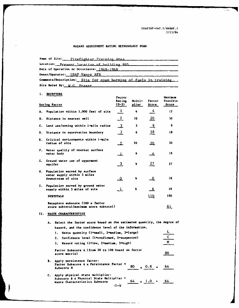
USAFERP-PAT. I/HARNF. 1
3/1 5/84
HAZARD ASSESSMENT RATING METHODOLOGY FORM
Name of Site: Firpfighrpr Train.ing ArpaLocation: P'npnqP_ .p, t _ nrafinn nf hjjiltdjn qqS
Date of Operation or Occurrence: 1948-1968
Owner/Operator: USAF Vance AFB
Coe nts/Description: Site for onen burning of fuels in training
Site Rated By: . .,, Frapr
I. RECEPTORS
Factor maximumRating Multi- Factor Possible
Rating Factor (0-3) pier Score Score
A. Population within 1,000 feet of site 1 4 4 12
A. Distance to nearest well 2 10 20 30
C. Land use/zoning within 1-mile radius 3 3 9 9
D. Distance to reservation boundary 3 6 18 18
E. Critical environments within 1-mile
radius of site 10 2& 30
F. Water quality of nearest surface
water body 6 18
G. Ground water use of uppermost
aquifer 3 9 27 27
H. Population served by surfacewater supply within 3 miles
downstream of site 6 0 18
1. Population served by ground water
supply within 3 miles of site 1 6 6 18
SU&TOTALS 110 180
Receptors subscore (100 x factorscore subtotal/maximum score subtotal) 61
It. WASTE CHARACTERISTICS
A. Select the factor score based on the estimated quantity, the degree of
hazard, and the confidence level of the information.
I. Waste quantity (1-small, 2-medium, 3-large) L
2. Confidence level (I-confirsed, 2-suspected) C
3. Hazard rating (l-low, 2-medium, 3-high) M
Factor Subscore A (from 20 to 100 based on factor
score matrix) 80
B. Apply persistence factor:
Factor Subacore A x Persistence Factor -
Subscore 5 80 . 0.8 . 64
C. Apply physical state multiplier:Subscore B x Physical State Mtultiplier -
Waste Characteristics Subscore 64 x 1.0 - 64
G-9
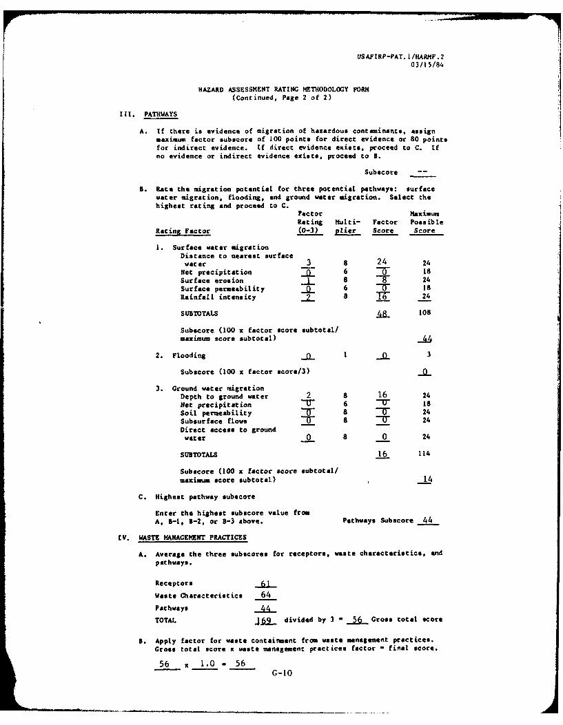
USAFIRP-PAT. I/IARMF.203/1 5/84
HAZARD ASSESSMENT RATING METHODOLOGY FORM(Continued, Page 2 of 2)
111. PATHWAYS
A. If there is evidence of migration of hazardous contaminants, assign
maximum factor subscore of 100 points for direct evidence or 80 pointsfor indirect evidence. If direct evidence exists, proceed to C. if
no evidence or indirect evidence exists, proceed to B.
Subscore --
B. Rate the migration potential for three potential pathways: surface
water migration, flooding, and ground water migration. Select thehighest rating and proceed to C.
Factor MaximumRating ulti- Factor Possible
Racing Factor (0-3) plier Score Score
1. Surface water migrationDistance to nearest surfacewater 3 8 24 24
Net precipitation 6 0 18Surface erosion 1 8 24Surface permeability 6 T 18Rainfall intensity 8 _- 24
SUBTOTALS 108
Subscore (100 x factor score subtotal/maximum score subtotal)
2. Flooding J - 3
Subscore (100 x factor score/3)
3. Ground water migration
Depth to ground water 2 8 16 24
Net precipitation 6 18
Soil permeability T 8 24
Subsurface flows 8 8 _-0 24
Direct access to groundwater 0 8 0 24
SUBTOTALS 16 114
Subscore (100 x factor score subtotal/
maximum score subtotal) 14
C. Highest pathway subscore
Enter the highest subscore value from
A, 5-1, 5-2, or B-3 above. Pathways Subscore 44
[V. WASTE MANAGEMENT PRACTICES
A. Average the three subscores for receptors, waste characteristics, and
pathways.
Receptors
Waste Characteristics 64
Pathways .A
TOTAL jLfi_ divided by 3 - 56 Gross total score
B. Apply factor for waste containment from waste management practices.
Gross total score x waste management practices factor - final score.
56 x 1.0 - 56G-10
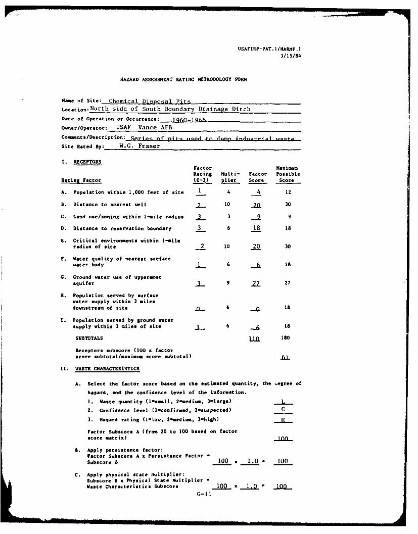
USAFIRP-PAT. I/HARMF.I3/15/ 84
HAZARD ASSESSMENT RATING METHODOLOGY FORM
Name of Site: Chemical Disoai Ijits
Location:North side of South Boundary Drainage Ditch
Date of Operation or Occurrence:- I goIRq
Owner/Operator: USAF Vance AFB
Comments/Description: Ser~.e Of pit- itq.d I -n r..,mp i ,,.-t-vra ,mate
Site Rated By: W.G. Fraser
I. RECEPTORSFactor MaximumRating Multi- Factor Possible
Rating Factor (0-3) elier Score Score
A. Population within 1,000 feet of site 1 4 .4 12
B. Distance to nearest well .2_ 10 M 30
C. Land use/zoning within 1-mile radius 3 3 9 9
D. Distance to reservation boundary 3 6 18 18
E. Critical environments within 1-mile
radius of site 2 10 20 30
F. Water quality of nearest surface
water body 1 6 6 18
G. Ground water use of uppermostaquifer 3 9 27 27
H. Population served by surface
water supply within 3 milesdownstream of site 6 18
I. Population served by ground watersupply within 3 miles of site 6 18
SUBTOTALS M 180
Receptors subscore (100 x factor
score subtotal/maximum score subtotal) .L_
II. WASTE CHARACTERISTICS
A. Select the factor score based on the estimated quantity, the 4,egree of
hazard, and the confidence level of the information.
1. Waste quantity (1small, 2-medium, 3-large) L
2. Confidence level (l-confirmed. 2-suspected) C
3. Hazard rating (I-low, 2mmedium, 3-high) H
Factor Subscore A (from 20 to 100 based on factorscore matrix)
B. Apply persistence factor:Factor Subscore A x Persistence Factor -
Subscore B 100 x 1.0 - 100
C. Apply physical state multiplier:Sub.core 5 x Physical State MultiplierWaste Characteristics Subscore 100 x 1.0 " ion
G-II

USAFIRP-PAT. L/HARMF .203/15/84
HAZARD ASSESSMENT RATING METHODOLOGY FORM
(Continued. Page 2 of 2)
Ill. PATHWAYS
A. If there is evidence of migration of hazardous contaminants, assign
maximum factor subscore of 100 points for direct evidence or 80 points
for indirect evidence. If direct evidence exists, proceed to C. if
no evidence or indirect evidence exists, proceed to B.
Subscore --
B. Rate the migration potential for three potential pathways: surfacewater mgration, flooding, and ground water migration. Select thehighest rating and proceed to C.
Factor aximumRating Multi- Factor Possible
Rating Factor (0-3) plier Score Score
1. Surface water migrationDistance to nearest surface
water 8 24 24Met precipitation 6 .. 18
Surface erosion 8 L 24
Surface permeability 6 f) 18
Rainfall intensity 2 8 16 24
SUBTOTALS 108
Subscore (100 x factor score subtotal/
maximum score subtotal) 52-
2. Flooding _0_ 3 _0
Subscore (100 x factor score/3) 0
3. Ground water migration
Depth to ground water 8 16 24
Net precipitation 6 18
Soil permeability 8 24
Subsurface flows 8 24Direct access to ground
water 8 24
SUBTOTALS 114
Subacore (100 x factor score subtotal/
maximum score subtotal) 21
C. Highest pathway subscore
Enter the highest subscore value from
A, B-1, 3-2, or 3-3 above. Pathways Subscore 52
IV. WASTE ANAGUEMNT PRACTICES
A. Average the three subscores for receptors, waste characteristics. and
pathways.
Receptors 61
Waste Characteristics 100
Pathways 52
TOTAL 711 divided by 3 - 7 1 Gross total score
B. Apply factor for waste containment from waste management practices.
Gross total score x waste management practices factor a final score.
71 1 1.0 - 71- - -G-12