UNCLASSIFIED AD - DTICQUICK CLAY FLOWAGE (THIXOTROPY ?) The mass movement of quick clays has been...
78
UNCLASSIFIED AD 414488 DEFENSE DOCUMENTATION CENTER FOR SCIENTIFIC AND TECHNICAL INFORMATION CAMERON STATION. ALEXANDRIA. VIRGINIA UNCLASSIFIED
Transcript of UNCLASSIFIED AD - DTICQUICK CLAY FLOWAGE (THIXOTROPY ?) The mass movement of quick clays has been...

UNCLASSIFIED
AD 414488
DEFENSE DOCUMENTATION CENTERFOR
SCIENTIFIC AND TECHNICAL INFORMATION
CAMERON STATION. ALEXANDRIA. VIRGINIA
UNCLASSIFIED

NOTICE: 'When goverment or other dravings, speci-fications or other data are used for any purposeother than in connection with a definitely relatedgoverment procurement operation, the U. S.Government thereby incurs no responsibility, nor anyobligation vhatsoever; and the fact that the Govern-ment my have formulated, furnished, or in any vaysupplied the said drawings, specifications, or otherdata is not to be regarded by implication or other-vise as in any manner licensing the holder or anyother person or corporation, or conveying any rigtsor permission to manufacture, use or seli anypatented invwention that my in any vey be relatedthereto.

AFCRL-63-253 6,.. .- 3AUGUS 1963
.. Paul F. Kerr
Richard S. Liebling
DDC
Prepared for
Geophysics Research DirectorateContract No. AF 19(604)8387 Air Force Cambridge Research LaboratQriesProject No. 8623 Office of Aerospace ResearchTask No. 862302 United States Air Force*Scientific Report No. I Bedford, Massachusetts

GLACIAL AND POST GLACIAL QUICK CLAYS
Paul F. Kerr and Richard S. Liebling
Paul F. KerrNewberry Professor of MineralogyDepartment of GeologyColumbia UniversityNew York 27, New York
Contract No. AF 19(604)8387
Project No. 8623
Task No. 862302
Scientific Report No. 1
AFCRL-63-253
August 1963
Prepared
for
Geophysics Research Directorate
Air Force Cambridge Research Laboratories
Office of Aerospace Research
United States Air Force
Bedford, Massachusetts

Requests for additional copies by Agencies of the
Department of Defense, their contractors, and other Government
agencies should be directed to the:
ARMED SERVICES TECHNICAL INFORMATION AGENCY
ARLINGTON HALL STATION
ARLINGTON 12, VIRGINIA
Department of Defense contractors must be established
for ASTIA services or have their "need-to-know" certified by
the cognizant military agency of their project or contract.
All other persons and organizations should apply to the:
U.S. DEPARTMENT OF COMMERCE
OFFICE OF TECHNICAL SERVICES
WASHINGTON 25, D. C.

GLACIAL AND POST GLACIAL QUICK CLAYS
Paul F. Kerr and Richard S. Liebling

ABSTRACT
Essentially horizontal deposits of glacial and
postglacial marine clays, long static in flat terrain,
may suddenly display mass flowage with destructive con-
sequences. The nature of the clays and the circumstances
involved in their behavior have been the subject of
study.
The mineralogy of these clays, known as quick clays,
has been determined for samples from Scandinavia, Canada
and the northeastern United States. Sheet layer silicates
constitute the greater part of the clay size fraction.
Illite and chlorite occur most frequently, but inter-
layered illite-montmorillonite is common. Interlayered
chlorite-montmorillonite occurs infrequently; interlayered
illite-vermiculite is present in one sample. Quartz,
feldspar, hornblende, and calcite predominate in the
coarser size fractions and often occur in the clay size
fraction.
Particle size measurements of non-quick clays yield
an average amount of material less than two microns of
31.6 per cent by weight, but in quick clays the amount is
57.3 per cent. Comparative samples of glacial fresh water
clays contain smaller amounts of colloidal size particles
than marine clays.
Chlorinity tests show that pore water salinity of
marine quick clays, believed to have been about 35 grams
per liter when the clay was deposited, now ranges from

2
0.3 to 15 grams per liter.
Measurements show that the amount of water held by
quick clays generally exceeds 50 per cent in terms of
weight of water to weight of sediment; in some cases it
is as high as 80 per cent.
The major critical conditions which contribute to
quick clay movement in flat terrain appear to be: a
substantial quantity of flake-like particles of colloidal
size (equivalent to approximately 40 per cent or more
by weight of dry sample); a substantial quantity of water
(roughly 50 per cent); a reduction in electrolyte concen-
tration below about 5 grams of salt per liter; and a
random orientation of particles induced by coagulation
during deposition.
3
TABLE OF CONTENTS
Acknowledgments pg, 5
Introduction 6
Quick Clay Flowage (Thixotropy ?) 12
Nature and Distribution 14
Sources of Samples Investigated 18
Grain Size 21
Electrolyte Content of Pore Water 32
Water Content of Quick Clays 33
Mineral Constituents 34
Natural Leaching 52
Experiments on the Effects of Leaching 54
Conclusions 67
References Cited 69

4
LIST OF TABLES AND ILLUSTRATIONS
Figure 1. Quick Clay Slide Scar near Ottawa, Ontario. pg. 7
Figure 2. Quick Clay Slide, Type 1. 8
Figure 3. Quick Clay Slide, Type 2. 8
Figure k.. Cioss Section of Surte Quick Clay Slide. 9
Figure 5. Typical Appearance of Quick Clay Slide. 10
Figure 6. Intersecting Quick Clay Slide Sears alongthe Batiscan River near Ste. Genevieve,Quebec. 11
Figure 7. Quick Clay Slide Localities of South-eastern Canada. 15
Figure 8. Quick Clay Slide Localities of Norwayand Sweden. 16
Figure 9. Lake Champlain and Hudson River Valleys,
New York. 19
Table 1. Quick Clays: Colloidal Fraction. 23
Table 2. Non-Quick Clays: Colloidal Fraction. 23
Figures 10-15. Particle Size Analyses. 24-29
Table 3. Salinity of Pore Water. 32
Table 4. Natural Water Content of Some Canadian andSwedish Quick Clays. 33
Figures 16-24. X-ray Diffraction Patterns of ClayMineral Constituents. 40-48
Table 5. Mineral Constituents of Quick and Non-QuickClays. 51
Figure 25. X-ray Diffraction Pattern of Fithian, Ill.,Illite. 56
Figure 26. Filter Cake Permeability with Leaching. 59
Figure 27. Relative Shearing Strengths of LeachedFilter Cakes. 60
Figure 28. Changes in Filter Cake Volume with Leaching. 61
Figure 29. Sediment Volume as a Function of Clay Fraction. 63
Figure 30. Volume Changes in Filter Cakes Leached withDistilled Water as a Function of Clay Fraction. 64

5
ACKNOWLEDGMENTS
The authors wish to express their gratitude to
Professors V. K. La Mer, H. Linford, and F. Donath, in
the departments of chemistry, chemical engineering, and
geology, respectively, who gave generously of their time
in suggesting experimental procedures and in reviewing
the results of this study. The authors are also indebted
to Dr. Justus Osterman, of the Swedish Geotechnical
Institute, Dr. I. Th. Rosenqvist, of the Norwegian Geo-
technical Institute, and Dr. Richard Kerr, of the Canadian
Geological Survey, for their cooperation in providing
samples for this study. Stimulating conversations have
been held with Professors Ralph J. Holmes and William
Farrand, both in the Columbia Department of Geology, and
with many members of the mineralogy group at Columbia,
in particular, Arthur M. Langer. The advice of Miss
Jacqueline C. Kane of the chemical engineering depart-
ment, was of great aid in constructing the experimental
apparatus. The assistance of Dr. R. F. Legget and his
associates of the National Research Council of Canada
is gratefully acknowledged. The assistance of Mr. Manuel
Rivero in conducting particle size analyses is very much
appreciated. This study has been made possible by the
support of the United States Air Force Cambridge Research
Laboratories.

6
INTROMJCTION
The term quick clay has been applied to a clay mass
which may rapidly and spontaneously undergo remoulding
being converted from a solid to a viscous liquid (Reusch, 1901).
In the process of remoulding, a quick clay first loses
shearing strength (Murayama and Hata, 1957; Newland and
Allely, 1957), following which smaller increments of
additional stress produce correspondingly greater strains
than required to cause the initial remoulding. Thus
continued application of stress causes the clay to be
remoulded more rapidly, and eventually the force required
to produce strain becomes essentially imperceptible.
As found as earth features, large scale slides or flows
may result.
Quick clay slides may be initiated by some minor
disturbance such as heavy traffic, implacement of pilings,
slides, explosions, or earthquakes. The initial distur-
bance produces enough remoulding to reduce the shearing
strength below the pressure exerted by the overburden on
the clay. The static column then acts to remould the
clay, thereby reducing the shearing strength even further.
The effect is cumulative and the mass is rapidly trans-
formed into a thick flowing liquid.
Two common forms of quick clay slide behavior have
been observed (Meyerhof, 1957): (1) blocks of clay
and silt rotate forward in a clay-water slurry having
the consistency of lubricating oil (Figure 2); (2) forward

7
displacement of liquid material occurs (Figure 3). In
(1), the disturbance starts from the foot of the slide
and proceeds toward the head. In (z), movement is pro-
pagated from the head to the foot. The slide at Surte
(Figure 4) is an example of type 2.
Slides occur on slopes which range from less than
10 (Caldenius and Lundstrom, 1956) to 200 (Eden, 1956),
with low slopes being common. The slide cavity may
assume the shape of a pear in plan view, wide at the
head and narrow at the neck (Figure 5), as illustrated
by a slide near Ottawa, Ontario (Figure 1; see Crawford, 1961).
The liquid mass at Ottawa flowed outward from a low
terrace, forming a wide apron. Many such slides occur in
groups, as shown by an area along the Batiscan River near
Ste. Genevieve, Quebec (Figure 6).
The mass of material
disturbed during a quick
clay slide may range from
250,000 cubic yards as at
Rimouski, Quebec (Hurtubise
and Rochette, 1956) to
25,000,000 cubic yards as Figure 1. Quick Clay SlideScar near Ottawa, Ontario.
at St. Alban, Quebec Courtesy of the Royal Cana-dian Air Force. Air Photo
(LaFlamme, 1894). The A17264-3.
duration of movement may range from two to three minutes
as at Surte,-Sweden (Caldenius and Lundstrom, 1956) to
a half hour, as at Rimouski, Quebec (Meyerhof, 1953).

head former surface
20
200 300FT
Figure 2. Quick Clay Slide, TYPe 1:Mlocks of Clay Rotating in a Clay-WaterSlurry. Vertical Ziaggeration: 5x.
hood former surface
00 I0000 300
Figure 3. Quick Clay Slide, Type 2:Total Liquefaction of Material. VerticalExaggeration: 5m.

0
Ci'
0D~ -
04WX
w
0 0
0
z06
CCA
c-c
z0~
0 0 L.
1331

10
Neck1110110 oi
Figure 5. A Typical Appearance of a Quick Clay Slide.

Figure 6. Intersecting Quick Clay Slide Scars along theBatiscan River near Ste. Genevieve, Quebec. Courtesy orthe Royal Canadian Air Force. Air Photo A 114596-23

12
QUICK CLAY FLOWAGE (THIXOTROPY ?)
The mass movement of quick clays has been referred
to as thixotropic (Rosenqvist, 1960). As originally
proposed (Peterfi, 1927), the term thixotropy refers to
the transformation of a gel into a liquid, with subse-
quent regelation, the thixotropic change being rapid and
produced by a shock. The phenomenon has been long re-
cognized (Kuthne, 1863; Howell, 1910). During the trans-
formation, the material suffers a loss in shearing strength,
which is regained after a lapse of time, without change
in water content. This return of shearing strength is
termed "thixotropic regain". Among those materials con-
sidered thixotropic, the regain is considerable. Early
studies by Schalek and Szegvari (1923a, 1923b) show
that ferric and tin oxide sols, and zirconium, scandium
and aluminum hydroxide sols, which gel with the addition
of electrolytes, are thixotropic.
Several chemists (van Olphen, 1956; Alexander and
Johnson, 1949; Kruyt, 1952; Green and Weltman, 1946)
believe that the development of a random mesh structure
of elongate particles is responsible for gelation.
Shaking or stirring destroys this structure, thereby
converting the gel into a sol. In time, Brownian move-
ment may enable the particles to reconstruct a random
mesh configuration.
Clay minerals may be thixotropic in varying degrees.
Some montmorillonite is thixotropic, at times exhibiting

13
a regain of as much as 130 per cent of its original strength
(Skempton and Northey, 1952). Sols containing as little
as 3 per cent bentonite are known to form gels which
revert to sols when shaken (Iler, 1955). This trans-
formation appears to require the presence of alkali
ions (Searle and Grimshaw, 1959). Illite may be moderately
to poorly thixotropic, its regain in strength probably
not exceeding 50 per cent. Kaolinite shows practically
no thixotropic regain.
According to some authorities, controlled laboratory
tests show that most quick clays regain little of their
former strength after remoulding (Grim, 1962; Skempton
and Northey, 1952). In the field, water is lost during
quick clay flowage and therefore any return to the ori-
ginal shearing strength cannot be strictly considered
thixotropic regain. Thus the term "thixotropic" when
used to describe quick clays is not precisely correct.
The word "quick" itself is adequate, because it refers
to a clay susceptible to spontaneous mass liquefaction
and flow.

14
NATURE AND DISTRIBUTION
Many quick clays are of Wisconsin and post-Wisconsin
age (Gadd, 1960) and seem to be restricted to higher
latitudes and possibly elevated valleys containing clays
derived from mountain glaciers. Quick clay slides have
long been known to occur in the St. Lawrence River Valley
in Canada (Figure 7), and the coastal areas of Norway
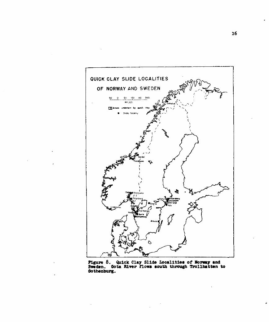
and Sweden (Figure 8). These areas were glaciated during
the Pleistocene with postglacial uplift of as much as
600 feet in Norway, 300 feet in Sweden (Meyerhof, 1957),
and 600 feet in Canada. Quick clay slides appear to
have occurred In the Portland, Maine, area during the
iud-l9th century (Morse, 1869). Occurrences of quick
clays in Vermont have been suggested (Prof. Burinister,
personal communication). Quick clays in wruthern Chile
have been reported (Dr. 0. Ericksen, personal communication).
Some clay slides in the Peruvian Andes may also be of this
type (Dr. V. Oppenheim, personal communication).
Quick clays represent fine-grained materials, apparent-
ly produced by ice sheet abrasion of bedrock, the fine
debris often being carried Into marine and brackish
water embayments by glacial melt waters. Upon reaching
saline waters, the fine particles become coagulated by
sodium chloride and other salts in solution and rapidly
settle. Toward the close of the Pleistocene, marine
embayments were formed by the influx of sea water into
recently glaciated areas still depressed from the weight

15
-J Z
, jU,
e)w w
U) i
w1
7CifS
]P.me r ulkC8 481d Socl. l so" olhetenCn
16
QUICK CLAY SLIDE LOCALITIES
OF NORWAY AND SWEDEN/,
50 0 50 100 150 200 I .
MIL ESr kl ,\
MArgos underlom by qcck -Joy C
S hde! lotoloty f
1>0 sid IIO.O
I / L
A /
N
Is
tindh sn
Figure 8. Quick Clay Slide Localities of Norwa andSweden. Gota River flows south through Trollhatten toGothenburg.

17
of the ice. Isostatic uplift of these areas resulted
in the retreat of the sea. One such invasion was the
Champlain Sea which occupied the St. Lawrence trough in
southeastern Canada about 11,000 years ago (Gadd, 1960).
Another similar embayment exists in the area now occupied
by the Gota River in Sweden (Caldenius and Lundstrom, 1956).
The trend of the Gota River Is parallel to the strike of
the cleavage, Jointing, and zones of weakness in the
gneissic bedrock. Borings through the valley fill indicate
that the valley is "U"-shaped in cross-section and that
glacial scouring during the last ice advance is respon-
sible for the cross-sectional profile. The ice retreated
some 12,000 to 14,000 years ago, followed by invasion of
the sea.

18
SOURCES OF THE SAMPLES INVESTIGATED
In this study field collections of clays have been
made and specimens have been secured of clays from a
considerable number of slide-producing areas, plus several
similar clay samples from non-slide areas studied foi
comparison. Among the quick clays studied, 4 are from
Sweden*, 1 from Norway**, 1 from Maine, and 9 from Canada.
Among the non-quick clays, 4 are from Canada and 8 are
from New York State (Figure 9). The Canadian quick clay
localities are Rimouski, Ste. Genevieve, St. Alban,
St. Thuribe, St. Stanislas, St. Vallier, Nicolet, Portneuf,
all in Quebec, and Hawkesbury, Ontario.
The Canadian samples are all of glacial marine
origin. Two Swedish quick clays from Vesten and Dykalla
are of marine origin, whereas a sample from Rosersberg
is of fresh water origin. The remaining two samples from
Oslo, Norway and Portland, Maine, are of marine origin.
The quick clays from all localities studied are dark
blue-gray when wet and light gray when dehydrated.
The 4 Canadian clays somewhat similar in appearance
but supposedly non-quick in type are from Ste. Anne de
Beaupre, St. Joseph de la Rive, Trois Pistoles, and the
east coast of Ellesmere Island on Darling Peninsula.
The clays from Ste. Anne de Beaupre and St. Joseph de
*Swedish quick clays were received through the courtesyof Dr. Justus Osterman of the Swedish Geotechnical Institute
**Supplied through the courtesy of Dr. I. Th. Rosenqvist,
of the University of Oslo.

19
le.
LAKE CHAMPLAINAND HUDSON RIRER
VALLEY% NEW YORK
~/
¢En..I" . .
N- pefte
Figure 9. lake Champlain and Hudson River Valleys,NOW York.

20
la Rive were collected from embankments containing
lenses of coarse material. Such deposits may have been
formed close to a glacier margin and therefore accumulated
under fresh or brackish water conditions rather than
marine. They are dark gray when wet but light gray when
dry. The sample from Trois Pistoles is marine, but,
unlike the other St. Lawrence Valley clays, is medium
brown when wet; after drying, the clay turns light tan.
The sample collected from Darling Peninsula on Ellesmere
Island represents clay deposited from melt waters along
a stream bank; it is therefore fresh water clay*.
The clay is brown when wet, and alters to light brown
upon drying. The remaining non-quick clays were collected
in New York State: Keeseville, New Paltz, Dutchess
Junction, Glasco, Mechanicville, Plattsburg, Haverstraw,
and Whitehall. The Plattsburg and Whitehall samples are
brown, but dry to a light tan. The others are gray when
moist, and light gray when dry. The clays from Plattsburg,
Keeseville, and Whitehall are from the Lake Champlain
area, and were deposited in a southern extension of the
ancient Champlain Sea. The Plattsburg and Whitehall sam-
ples may be marine clays. The other clays, from the
Hudson River Valley, are considered lacustrine.
*Collected by Dr. Richard Kerr of the Geological Surveyof Canada in the summer of 1961.

21
GRAIN SIZE
Grain size distribution was determined for each clay
using the Bouyoucos hydrometer method (ASTM, 1959). In
this method, 50 grams (dry weight) of each sediment are
immersed in 125 ml of a 4 per cent solution of sodium
hexametaphosphate for 24 hours. After 24 hours, the
sediment plus solution are agitated in a Waring Blendor
for one minute. 875 ml of distilled water are then
added and the mixture placed in a Kimax liter cylinder.
After being shaken 120 times in one minute, the sediment
is allowed to settle. Bouyoucos hydrometer readings
in grams per liter are then taken after intervals of
2, 5, 15, 30, 60, 250, and 1440 minutes. With the proper
density and temperature corrections, particle sizes in
equivalent diameters are calculated and particle size
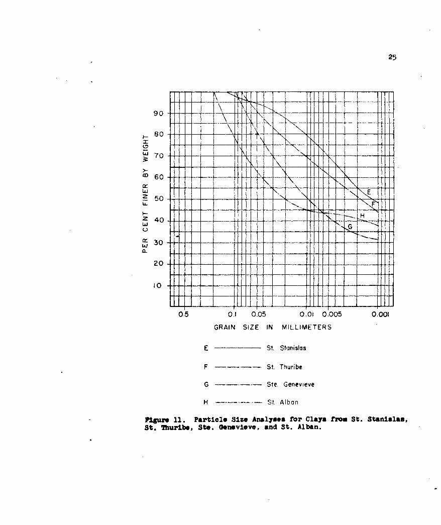
distribution curves plotted (Figures 10-15).
Tables I and 2 summarize the minus two micron portions.
The average amount of minus two micron material for the
quick clay samples is 57.3 per cent by weight. The average
amount of minus two micron material for the non-quick
clays examined is 31.6 per cent by weight. The per cent
of less than two micron material ranges from 27 to 82
in quick clays, whereas the range in non-quick clays is
from 11 to 77 per cent. However, whereas 10 of the 15
quick clays contain 50 per cent or more of the two micron
material, only two of the 12 non-quick clays contain 50
per cent or more of the same size particles. Using a level

22
of significance of .01, a "t" test shows that the two
types of clay contain significantly different amounts
of less than two micron material. Data (Crawford, 1961)
on quick clays from Beauharnois, Quebec, Massena, Ontario,
and Ottawa, Ontario, show the following amounts of the
minus two micron fraction: 47-72, 30-55, 55-80 per cent
respectively. The samples from Trois Pistoles, Plattsburg,
and Whitehall, are probably potential quick clays although
no slides were observed nearby. They contain amounts of
minus two micron material comparable with amounts found
in quick clays. The geological situation is also likely.
It is necessary to consider the factors affecting
grain size distribution in sediments to explain the
significantly different amounts of fine-grained material
in quick and non-quick clays. These factors include
physical and chemical properties of the source material,
climate, erosional agents, and depositional environment.
Mineralogic similarities among the clays suggest that
the source materials for these sediments were probably
similar. In the regions sampled, the Pleistocene cli-
matic conditions were probably more or less alike and
the type and degree of weathering, except for local
differences caused by topographic and soil biota vari-
ations, were probably also essentially the same. Al-
though it is not certain that all these clays are the
product of glacial abrasion, no doubt most are (Ries, 1900;
Caldenius and Lundstrom, 1956; Eden and Crawford, 1957;

23
TABLE 1
Quick Clays: Colloidal Fraction (Less than Two Microns)
Clay Locality Colloidal FractionType* (Wt. Per Cent)
M Rimouski, Que.** 27M Ste. Genevieve, Que.M St. Alban, Que.1M Oslo, Norway 45M Portland, Me. 47M St. Thuribe, Que. 51M Dykalla, Sweden 55M St. Stanislas, Que. 55M Vesten, Sweden (two samples) 63, 65M St. Vallier, Que. 68M Nicolet, Que. 72F Rosersberg, Sweden 75M Portneuf, Que. 80M Hawksbury, Ont. 82
*M-marine, F-fresh*Considered a non-quick clay by Meyerhof (1953).
TABLE 2
Non-Quick Clays: .Colloidal Fraction (Less than Two Microns)
Clay Locality Colloidal FractionType* (Wt. Per Cent)
F/B Ste. Anne de Beaupre, Que. 11F Ellesmere Island 15N Keeseville, N. Y. 17F/B St. Joseph de la Rive, Que. 17F Naverstraw, N. Y. 18F New Paltz, N. Y. 19F Thutchess Junction, N. Y. 25F Glasco, N. Y. 4oF Mechanicville, N. Y. 45N Plattsburg, N. Y. ** 45N Troia Pistoles, Que. 51N Whitehall, N. Y.** 77
* -marine, F-fresh, F/B-fresh or brackish*~Probably potential quick clays

24
90 ---_ .... .. A v iv..........
8 0 -- .... .
70 70
crrU- ] i
z 40__ 1
z 0 4. 0 V- --- ------- .....30
7 -I
0.5 0.1 0.05 00! 0.005 0.001
GRAIN SIZE IN MILLIMETERS
A Hawkesbury
B St. Vallier
C Rimouski
D Trots Pistoles
Figure 10. Particle Size Analyses for Clays from Howkesbury,St. Vallier, R1imouski, and Trois Pistoles.
25
\ _ _ _ __ _ .../< \
90 .i ----- "i f-80 -- FjH
"' 7 0 . ....-
a' 60 -
1- ' .
Z 40
uj G20.
20 .......
0.5 01 0.05 0.01 0.005 0.001
GRAIN SIZE IN MILLIMETERS
E St Stanislas
F St. Thuribe
G Ste Genevieve
H St. Albon
Flire 11. Particle 81:e Analyses for Clays from St. Stanislas,St. Thuribe, Ste. Genevieve, and St. Alban.

26
90 ---.-- 2_
'M60-
Z 40.+I-tt\
20[.-j
0.5 0.1 0.05 0.01 0.005 0.001
GRAIN SIZE IN MILLIMETERS
I Nicolet
J Portneuf
K St. Joseph de lo Rive
L -- - -Ellesmere Island
M -. Ste. Anne de Beoupre
* Figure 12. Particle Size Analyses for' Clays from Nicolet,St. Joseph do la Rive, Portnbuf, Ellesmere Is., and Ste.Anne do Bsaupi's.

27
90 c__u8 0
70 47thM 60 -
SII
-f 50j\\0
30 Ell*
K of-I---4
20 ji10 - . -
0.5 0.1 0.05 0.01 0.005 0.001
GRAIN SIZE IN MILLIMETERS
N Vesten
0 Oykalla
P Rosersberg
Q Oslo
Flguze 13. Particle Size Analyses for Clays from Vesten,Dykalla, Rosersberg, and Oslo.

28
R
'M60 -
LL
I-U
Z 40 * -
Cc30 ---20 ------
10- - - - -
0.5 0.1 0.05 0.01 0.005 0.001
GRAIN SIZE IN MILLIMETERS
R Glasco
S ----- Haverstrow
T - -- Dutchess Junction
U --- *-New Palfz
Figure 1ii. Particle Size Analyses for Clays from Glasco,kaverstrsw, Duchess Junction, and Now Paltz.

29
_ 80 -7
I,, 7 0 ... .
6 0 . .. -+
_ 5 0 . .
Z 40.
C ) . . . .. ..c r 3 0 . . .... .
20 -- ~ - ~
10
0.5 0.1 0.05 0.01 0.005 0.001
GRAIN SIZE IN MILLIMETERS
V Keesevulle
W -------- Mechanicville
X -- - * - Portland
Y - - - --- Plattsburg
Z . ....Whiteha ll
Figure 15. Particle Size Analyses for Clays from KeesevillejNechanicville, Plattsburgh, Whitehall, arnd Portland.

30
Meyerhof, 1957; Gadd, 1960).
The significant difference among these clays is
that some were deposited in marine waters and others
in fresh waters. When the clays are classified as marine
or fresh and the amount of colloidal size fraction present
in each compared (Tables 1 and 2), it is found that, in
general, the fresh water samples contain fewer colloidal
size particles than marine clays. The average amount,
in terms of weight per cent, of less than two micron
material in the marine clays is 54.1, whereas the average
amount in fresh water clays is 23.7 per cent. The difference
between fresh water clays and marine clays may be explained
as follows: fine particles (less than two microns) are
not rapidly coagulated in a fresh water environment and
therefore remain in suspension long after coarser particles
have settled. Continued transport of the fine fraction
by currents may be expected to prevent the fine fraction
from accumulating with the coarser material. Marine
clays are much finer, since in sea water, fine particles
are rapidly coagulated into large masses by sodium chloride
and other dissolved salts. Such large masses settle
rapidly, thereby contributing significantly to the mass
of sediment. Therefore, as a general rule, where most
other factors are the same, fresh water clays are coarser
than marine clays. Table I shows that most of the quick
clays are quite fine-grained and that all, save one,

31
were deposited in a marine environment. Since fine-grained
sediments may be particularly sensitive, a marine depositional
environment is probably an important factor contributing
to the formation of quick clays. Though quick clays seem
to be closely associated with marine waters, Soderblom (1960)
has reported the existence in Sweden of non-marine post-
glacial quick clays.

32
ELECTROLYTE CONTENT OF PORE WATER
Pore water salinity analyses of the Swedish clays
and some Canadian clays (Crawford, 1961) show that the
clays from slide areas have a salinity considerably
less than that of sea water (35 grams per liter).
The fresh water clay from Rosersberg, Sweden, also contains
little salt. This is to be expected since fresh water
salinities generally range from .01 to 1.0 grams per
liter.
TABLE 3
Salinity of Pore Water
Sample Salinity (gr/1)
Vesten, Sweden 1.1-1.2Dykalla, Sweden 0.4Rosersberg, Sweden 1.0Nicolet, Que. 5.0-9.0Beauharnois, Que. 0.4Massena, Ont. 0.6-2.0Hawkesbury, Ont. 0.3Ottawa, Ont. 0.5-15.0

33
WATER CONTENT OF QUICK CLAYS
The amount of water held by quick clays generally
exceeds 50 per cent, in terms of weight of water to
weight of sediment; in some cases (Crawford, 1961) it
is as high as 80 per cent (Table 4). The high per cent
of water is probably attributable to substantial amounts
of colloidal material and a high void index (Skempton
and Northey, 1952; Rochette, 1956). The high void index
of quick clays probably accounts for their shrinkage
and swelling during dry and wet seasons (Crawford, 1961;
Barcos and Bozozuk, 1957).
TABLE 4
Natural Water Content of Some Canadian and Swedish QuickClays. (Crawford, 1961, Canadian Localities; Osterman,personal communication, Swedish Localities)
Locality Natural Water Content(Wt. of Water per Wt.of Sediment)
Vesten, Sweden 64Nicolet, Que. 53
65St. Thuribe, Que. 44Beauharnois, Que. 68Massena, Ont. 60Hawkesbury, Ont. 80Ottawa, Ont. 8045
Dykalla, Sweden 51Rosersberg, Sweden 59
34
MINERAL CONSTITUENTS
Earlier mineralogic studies of clays of the Ottawa
and St. Lawrence River Valleys seem to indicate that the
clays vary somewhat in their mineralogic composition.
According to Meyerhof (1957), the clays and silty clays
of the region contain appreciable amounts of illite,
whereas, the silts are dominantly quartz and feldspar.
Eden and Crawford (1957) state that studies using X-ray
diffraction and DTA techniques reveal that the Champlain
Sea clays are composed mainly of "illite with a tendency
toward mica, plagioclase feldspars, quartz and chlorite".
They also report interstratification of illite and chlorite.
Barcos and Bozozuk (1957) claim that the clays of the
Ottawa and St. Lawrence Valleys (the so-called Leda clays)
contain substantial quantities of montmorillonite. The
Leda clays are described by Gadd (1956) as predominantly
quartz and feldspar, containing only small amounts of
clay minerals. In a study of 56 samples of clays and
shales from eastern Canada and New England, Allen and
Johns (1960) observed that hydrous micas and chlorite
are the dominant clay minerals. Quartz and feldspars
are also present, the quartz being far more abundant.
Interlayered mica-chlorite is not common and montmorillonite
occurs rarely. Mineralogic analyses of Champlain Sea
sediments conducted by Brydon and Patry (1961) showed
that quartz, feldspars, amphibole, micas, and chlorite

35
occur in the clay fraction as well as in the silt and
sand fractions. The clays and micas are more abundant
in the clay fraction. Beland (1956), in an analysis of
Leda clay from Nicolet, Quebec, found the sediment to
be predominantly quartz and feldspar, with mica, mont-
morillonite, and kaolinite occurring in small amounts only.
Karrow (1957) noted the presence of chlorite, illite,
amphibole, quartz, feldspar, and sometimes calcite in
samples of Champlain Sea clay. Quartz and feldspar
together account for probably no more than 20 per cent
of the clay fraction. Grim (in Terzaghi and Peck, 1948)
found that, in general, the silt fraction is predominantly
quartz and calcite, and that the clay fraction is mostly
mica-like illite and montmorillonite. The clay involved
in the St. Thuribe slide contains mostly fine quartz
with a little mica and possibly a trace of montmorillonite
(Grim, in Peck, Ireland, and Fry, 1951). Rosenqvist (1960)
believes that the Norwegian quick clays are generally
illitic or chloritic and that quartz and feldspar are
abundant in the finest size fraction.
In this study, an investigation of the mineral content
of both quick clays and non-quick clays was made to
determine whether or not these two types of clay differ
significantly and also, to determine in what way, if any,
the mineral assemblage in quick clays contributes to their
behavior.
36
Microscopic study showed that quartz, albite, micro-
cline, and muscovite were present in the sand and coarse
silt fractions of all clays. Hornblende, biotite, and
calcite are found in the sand and silt fractions of several
clays. Clay size particles cannot be easily resolved
under the ordinary microscope. Whereas valuable optical
data may be obtained on clay-size material of a single
mineral species, optical analysis of clay-size material
consisting of several minerals is exceedingly difficult.
Several attempts were made at determining refractive
indices. Because individual grains were not discernible,
determinations were obtained for the clay fraction as
a whole. Observed values ranged from 1.55 to 1.57.
Further analysis required the use of X-ray diffraction.
Mineral identifications were made with a Philips
X-ray diffractometer utilizing the spacings between the
basal atomic planes. Since clay mineral particles generally
are flake-like, with flat surfaces parallel to (001),
samples were sedimented so that the reflections observed
were essentially those diffracted from the atomic layers
parallel to (001).
The sedimented specimens were investigated in three
ways: (1) untreated, (2) after heating at 5500 C for two
hours, and (3) after spraying with glycol.
The common sheet silicates involved have been found
to be illite, chlorite, vermiculite, and montmorillonite.

37
A summary is given of the criteria used in distinguishing
the combination of these minerals found in the clays.
Illite: Significant illite reflections occur
at 10A, 5A, 3.33A, 2.5A, 2A, which
are not affected by heating at 5500C
or by glycolation. All quick clays
examined contain illite.
Chlorite: Significant reflections at 14A,
7A, 4.7A, 3.5A, and 2.8A indicate
the presence of chlorite. Generally,
the 7A reflection is more intense
than 14A. Heating at 5500C de-
stroys all of the reflections ex-
cept the 14A peak which becomes
much more intense. Glycolation
produces no effect on the reflections
(except for some rare chlorites).
Chlorite is a prominent constituent
of a number of quick clays but is
not always present.
Vermiculite: Significant reflections at 14A,
7A, 4.7A, 3.5A, 2.8A (correspond-
ing to chlorite) may indicate
vermiculite. However, in ver-
miculite, the 14A reflection

38
is ordinarily more intense than
the 7A reflection. In addition,
heating at 550 C generally causes
the collapse of the 14A reflection
to 10A, because of the removal of
water from interlayered positions;
at the same time the other re-
flections are destroyed. Gly-
colation may cause a displacement
of the 14A to higher spacings.
However, for ordinary vermiculite,
the displacement is not great,
often negligible. Vermiculite
occurs in a number of quick clays.
Montmorillonite: Reflections at 14A and 4.5A in-
dicate the presence of montmorillonite.
Heating at 550°C produces a dis-
placement of the 14A reflection
to about 1OA and a strong reflection
at 3.2A appears. Glycolation
results in a pronounced increase
in the basal layer separation
causing a displacement of the
14A reflection to 15A-17A.
Several quick clays contain mont-
morillonite.

39
The criteria (Molloy and Kerr, 1961; Brindley, ed, 1951)
used serve as guides to identification. Occasionally
only a few of the reflections characteristic of a particular
mineral are recorded. In addition, unless heating is
continued long enough, dehydration may not be complete
and therefore the basal spacings may not collapse as much
as expected. Furthermore, during glycolation, the organic
liquid must be allowed to completely permeate the inter-
layer positions. Otherwise only a partial expansion of
the basal layers will occur. In the clay mineral de-
scriptions given the term montmorillonite applies to a
clay with an expanding structure.
Figur s 16 to 24 furnish X-ray diffractometer patterns
showing the clay mineral reflections. Since the (003)
reflection of illite and (101) reflection of quartz overlap
at about 3.34A (26.60 2), the (100) quartz reflection
at 4.26A (20.802@) has been indicated by a small apex
at the peak intensity position. The (101) quartz re-
flection is 2.85 times more intense than quartz (100).
Any excess is the illite contribution. Several feldspars,
the remaining quartz, calcite and hornblende reflections
have been eliminated to avoid confusion.
The following abbreviations have been used for the
diffractometer patterns: I-illite; C-chlorite; M-mont-
morillonite; V-vermiculite; Mu-muscovite; C-M-chlorite
interlayered with montmorillonite; C-V-chlorite inter-

40
layered with vermiculite; I-M-illite interlayered with
montmorillorite; I-V-illite interlayered with vermiculite;
arnd Q-quartz.
5W c1
Figure 16. X-ray Diffractomster Patterns of Clay MineralConstituents for Clays from Oslo, Norway, and Portland, Nainie.s Pg. 39, paragraph 3, for explanation of abbreviations.

41
UNJTREATED
M i . ...
- 0 '4
I Gv
aY~ATa
doJ IQa i d
Rie u. e g 39,- prga 3,frepaaino
a
,,'
14
Feigure 17. X-ray Diffractometer Patterns or Clay MineralContituents for Clay. from Trois, Pistoles, Que., Ste. Arnsde Beaupre, Que., Ellesasere Island, arnd St. Joaeph de laRitve, Quo. See pg. 39, paragraph 3, for explanation atabbreviations.

~42
I
--
Quo., , St Ala, Qu. n pt aleQe e g 9
paragraph 3, for explanation of abbreviations.

Figure 19. X-ray Diffractometer Patterns or Clay MineralConstituents for Clays from Rosersberg, Sweden, Vesten,Sweden, and Dykalla, Sweden. See Pg. 39, Paragraph 3,fbr explanation of abbreviations.

44
GLYOLATMDC
Plgure 20. X-ray Dirfractomter Patterns of Clay MineralConstituents for Clays from Whitehall, N. Y., Keeseville,N. Y., and Plattsburg, N. Y. See p9. 39, paragraph 3,for explanation of abbreviations.

45
UNTREATED
GLYCCLATED
55O C.
oB
Figure 21. X-ray Diffractoeter Patterns of Clay MineralConstituents for Clays from St. Stanislas, Quo., and St.Thuribe, Quo. See pg. 39, paragraph 3, for explanationof abbivviations.

0 ~C c
UNTREATED
5W 0
Figre22 Xra DffacomterPatensofCly inra
Cositet fo Cly rmCmukQoNclt u.
and awksbuy, Ot. ee S. 3, pragaph , fr epla
natin ofabbrviaton0

47
C
LI' 9T i
cC
I i'~!9
Figure 23. X-ray Dlffractometer Patterns of Clay MineralConstituents for Clay from New Paltz, N. Y., Glasco, N. Y.,and hbveratraw, N. Y. See pg. 39, paragraph 3, for expla-nation at abbreviations.

C
UNTREATED
M.IC
I L [EE I I I
5 5000G
9
0
Figure 24&. X-ray Diffractonieter Patterns of Clay Mineral Con-itituents for Clays from D0utchess Junction, N. Y., and Mechanic-viule, N. Y. See pg. 39, paragraph 3, for explanation of abbre-viations.
49
Table 5 is a tabulation of the mineral identifications
of this study. In all cases, layer-structure minerals, largely
the clay minerals, are more abundant in the minus 2 micron
fraction than are the non-layer-structure minerals. In
almost all cases, illite is the predominant clay mineral.
The "illite" in this study has been identified, in part,
from well-defined 1OA reflections which show some broadening
toward lower angles. These reflections, though narrow,
are not as narrow as reflections from clay-size muscovite
flakes. Because illite and muscovite are structurally and
chemically similar, the "illite" may be degraded muscovite.
It has been observed in the laboratory that grinding
tends to produce poorly defined diffraction patterns
of phyllosilicates. It is possible that the "illite"
of these samples is really muscovite, the structure
having been partially destroyed by the grinding effect of
glacial scouring. Where interlayered between illite and
another component occurs, the interlayered component
never exceeds 10 per cent by volume.
Aside from illite, the next most abundant sheet
silicate is chlorite. Vermiculite occurs occasionally
and is almost always present when chlorite or interlayered
chlorite are absent. Vermiculite may represent degraded
chlorite. In all cases, save one, montmorillonite occurs
in minor quantities; the Plattsburg specimen, however,
contains major amounts of montmorillonite. In two samples
muscovite is present. Quartz, albite, and microcline

50
are present in almost all samples. Hornblende and cal-
cite occur in many samples and dolomite occurs rarely.
These minerals predominate over the clay minerals in
fractions coarser than clay size.
Mineralogically, there appears to be no significant
difference between quick and non-quick clay. This suggests
that the behavior of quick clays cannot be attributed
to the presence of any particular mineral or mineral
assemblage. In quick clay, flake-like minerals fon a
significant portion of the clay-size fraction, and the
clay-size fraction generally constitutes at least half
of the total clay sample. This high per cent of total
clay minerals is of importance in explaining quick clay
behavior.
Glacial scouring of the igneous-metamorphic shield
areas of Canada and Scandinavia supplied much of the
abundant quartz, feldspar, hornblende, illite and chlorite
of the quick clay. Additional amounts of these minerals
and some calcite were supplied to the Canadian clays by
the Paleozoic shales, slates, limestones, and marbles of
the St. Lawrence Valley. The Adirondack Mountain region
and widespread early Paleozoic shales, slates, and car-
bonate rocks supplied the minerals found in New York
clays.

51
TABLE 5
Mineral Constituents of Quick Clays
Sample I MU C v C-V C-M I-M I-V M Q F Ho Ca
Vesten, Swed. x X? x x x x nk xVesten, Swed. x x x x x x nk xDykalla, Swed. x X? x X? x x? xnk xRosersberg,
Swed. x x nk xSt. Vallier,
Que. x x X? x x nk x xRimouski, Que. x x x nkSt. Alban,
Que. x Xx x x n xSt. Thuribe,
Que. x x x nk xSt. Stanislas,
Que. x x x rik xSte. Gene-vieve, Que. x x x x nk x
Hawke sbury,Ont. x x x nk x x
Nicolet, Que. x x x nk xPortneuf,' Que. x x x x n xPortland, Me. x x x x n XOslo, Norway x x x nk
Mineral Constituents of Non-Quick Clays
St. Joseph dela Rive "Que. x X x nk x xTrois Pisto-les, Que. x x x x n x x
Ste. Anne deBeaupre. Que. x x x x nk xEllesmere Is. x x x x xPlattsburg,
N. Y. x x x n xKeeseville,
N. Y. x x x x nk x xWhitehall,
N. Y. x x x n xGlasco, N. Y. x x x n xNew Paltz,
N. Y. x x x nkHaverstraw,
N. Y. x x x nk xDutchessJunction, N.Y. x X x n x
Mecharicville,N. Y. x x x nk x
I, Illite; Mu, Muscovite; C, Chlorite; V, Vermiculite; Q, Quartz;F, Feldspar; n, Albite; kc, Microcline; Ho, Hornblende; Ca, Carbonate;M, Montmorillonite; C-V, Interlayered Chlorite-Vermiculite;C -M, Inte rlaye red Chlorite-Montmorillonite; I-M, interlayeredIllite-MontmorilJlonite; I-V, Interlaye red Illite -Vermiculite

52
NATURAL LEACHING
Several investigators have studied the effects
produced when sodium chloride is leached from quick clays.
Meyerhof (1957) noted that leaching reduced the remoulded
shearing strength of a sensitive clay to such an extent
that the clay became a viscous liquid. In a study of
some Norwegian quick clays, Rosenqvist (1960) observed
a considerable reduction in the salinity of the pore water
by natural leaching. The leaching was greatest on the
highest slopes where the hydraulic gradient was greatest.
Rosenqvist observed that leaching below 15 grams of salt
per liter produces a noticeable increase in sensitivity.
Skempton and Northey (1952) made similar observations.
On the other hand, Soderblom (1959) observed only a slight
increase in sensitivity when quick clays from the Gota
River Valley in Sweden were leached. According to Soderblom,
natural leaching of marine clay with water containing
carbon dioxide produces dilute solutions of sodium and
magnesium carbonate which act as dispersants, thereby
increasing sensitivity. Other natural dispersants are
alkali sodium humate, sodium sulphite, sodium silicate
and certain oxalates and phosphates (Soderblom, 1959).
Random stacking of clay particles produced by co-
agulation has been suggested to account for the behavior
of quick clays (Rosenqvist, 1952; Skempton and Northey, 1952).
The random structure is considered metastable and thus
easily disturbed. Because most quick clays are marine,

53
random stacking of clay particles has been attributed to
the coagulating effects of electrolytes. However, co-
agulation of clay particles suspended in distilled water
may be induced by freezing. Therefore, sediments of
fine coagulated material may accumulate in lakes experienc-
ing periods of freeze and thaw.
Many quick clays are found in areas which have been
glaciated. Following deglaciation these areas were up-
lifted several hundreds of feet. During uplift streams
cut deeply into unconsolidated sediments, producing steep
walled stream channels. Such steep banks may be unstable
and are easily undercut by stream action (Gadd, 1957)
or disturbed by an increase in load (Wenner, 1951).
Steep slopes may contribute to the instability of quick
clays, but most quick clay slides occur on shallow slopes,
some as low as 10 (Jakobson, 1952).

54
EXPERIMENTS ON THE EFFECTS OF LEACHING
Thus far it has been shown that most quick clays
are illitic marine sediments containing substantial
amounts of clay size material. They have undergone
extensive leaching and are particularly sensitive to
disturbance.
Adapting techniques described in a series of papers
by La Mer and Smellie (1959, 1962) and La Mer et al. (1957),
experimental procedures have been developed to simulate
deposition of clays in the marine environment and the
leaching processes which such clays undergo.
The behavior of quick clays may be related to changes
in the structural arrangement of the constituent minerals.
Such changes may be reflected in changes in sediment
volume, permeability, and shearing strength accompanying
leaching. Because particle arrangement may be affected
by particle shape, comparative experiments have been
conducted using Illite, which is flake-like, and quartz,
which is equidimensional. Illite and quartz were chosen
because they occur most commonly in the sediments under
investigation.
Because quick clays are commonly fine-grained, the
clay size fraction influence on sediment volume during
sedimentation and leaching has also been investigated.
Examining such factors as pore water electrolyte
concentration, particle size and particle shape may elu-
cidate the influence each exerts on quick clay behavior.

55
Clay filter cakes were prepared by vacuum filtration
of clay suspensions containing 12.6 per cent clay and
having an electrolyte concentration of 35 grams of sodium
chloride per liter. The electrolyte concentration used
is about the salinity of sea water. Natural leaching
was simulated by refiltering sodium chloride solutions
of lower concentration through the filter cake, using
newly prepared "marine" filter cakes with each less con-
centrated solution. Leaching was considered complete
when the rate of refiltration remained constant. A
record was made of the time required to refilter 35 ml
of each solution. The minus 44 micron fraction of Fithian,
Illinois, illite (Figure 25) was used in one set of re-
filtration experiments; quartz particles less than 44
microns in diameter, in another.
Because salinity changes appear to alter the shear-
ing strength of clay sediments, the relative shearing
strength of each filter cake was measured with a small
lead disk. During filtration the filter cake was permitted
to form around the disk, 4mm in diameter and imm thick,
located 20mm from the center and 8mm from the edge of
each filter cake. After leaching, the filter cake was
placed on a centrifuge, rotated at 1000 revolutions per
minute, and the number of seconds required to expel the
lead pellet recorded. The pellet method can be considered
analogous to Stoke's method for determining viscosity.
In Stoke's method, a sphere is permitted to settle under

56
S3A
IO.OA
I-M
! 5.0A
42A I
4.5A 7.IA
1 T' ' "-- -- -
25 20 15 10 5
DEGREES 20
Figure 25. X-ray Diffractometer Pattern of Fithian, Ill.,Illite. I, illite; I-M, illite Interlayered with mont-morillonite; M, montmorillonite; K, kaolinite; Q, quartz;A, angstroms. The amount of interlayered montmorilloniteprobably does not exceed 10 per cent.

57
the force of gravity through a medium whose viscosity
is desired. The time required to settle a certain dis-
tance is a measure of the viscosity. It was found that
the Stoke's method was inapplicable to the clay filter
cakes because the clay was too viscous to permit settling.
The centrifuge method overcomes this difficulty because
a force considerably greater than gravity is applied
to the pellet. As in Stoke's method, the time which
the pellet requires to cover a certain distance reflects
the viscosity. Time differences therefore reflect
relative viscosities. It was necessary to use a small
disk rather than a sphere to obtain a pellet of high
enough mass to move through the filter cake with the
revolutions per minute used. The results obtained using
a centrifuge were reproducible within 5 per cent. Be-
cause viscosity and shearing strength both depend in
the same way upon the internal cohesion of a material,
viscosity can be used as an indicator of shearing strength.
.Figures 26 and 27 show the results of these experi-
ments. Leaching of Fithian, Illinois, illite produces
a 60 per cent decrease in permeability between 0 and 5
grams of sodium chloride per liter (Figure 26). Between
5 and 35 grams, there is a permeability decrease of
30 per cent, the decrease becoming noticeable after
leaching below 15 grams per liter. A 40 per cent increase
in shearing strength occurs between 0 and 5 grams of

58
sodium chloride per liter (Figure 27). No significant
increase in shearing strength is observable until after
leaching below 10 grams per liter. In contrast, leaching
of the silica filter cakes produces no significant change
in permeability or shearing strength.
Filter cake volume changes occurring during leaching
have been noted. To observe volume changes, it was necessary
to deposit several filter cakes one upon another to ob-
tain a suitable column of material. Four illite filter
cakes yielded a volume of approximately 18,000 cubic
millimeters. Five silica filter cakes were required to
obtain the same volume. In all experiments, filter cakes
were subjected to a vacuum induced compressive stress of
14.2 pounds per square inch, as measured with a closed
tube manometer. Figure 28 shows that Fithian illite
undergoes a one-third reduction in volume when leached
with distilled water. Silica, in contrast, undergoes
no volume change with leaching.
The reduction in volume may be explained as follows:
deposition of clay minerals in a saline environment
produces a porous structure of irregularly arranged
particles, with water occupying the interstices as well
as adhering to each clay flake. Leaching below 5 grams
of sodium chloride per liter results in a pronounced
weakening of the structure causing it to collapse under
the vacuum induced pressure. Collapse forces out inter-
stitial water, but adsorbed water probably continues to

59
500-
0 Fithian, Illinois, Illte. < 44mirnUJ Cn 0 Silica, < 44 microns
_j 0 400 -
300-0 z40
200 0
W Cn
WQ 100-
'0 01 T1 T0 5 10 15 20 25 30 35
GRAMS PER LITER
CONCENTRATION OF NoCI SOLUTION USED TO LEACH ILLITEFILTER CAKES DEPOSITED IN A 35 GRAM PER LITERSOLUTION OF NoCI.
Figure 26. Filter Cake Permeability with Leaching.

60
Lii
60-
oz'z 0LLC- 50-
(LSCl)jr-,-JJ
-) 40-
(D 0 Siia <44icon
.
00
zY 0
wzJW
20 5 10 5 2o 25 3 4mo
GRAMS PER LITERCONCENTRATION OF NoCI SOLUTION USED TO LEAH ILLITE
FILTER CAKES DEPOSITED IN A 35 GRAM PER LITERSOLUTION OF NoGI.
NuTAe 27. R t Ove heaISng StOUen th of Heached
Filter Cakes.

61
24,000-
wj 18,000 .6w
CD 0 Fithian, Illinois, Illite, < 44micronso I 2~o Silica, < 44 microns
w
w
o6,000-
0 - I0 5 10 15 20 25 30 35
GRAMS PER LITER
CONCENTRATION OF Nodl SOLUTION USED TO LEACH dLLITEFILTER CAKES DEPOSITED IN A 35 GRAM PER LITERSOLUTION OF Nodl.
Figure 28. Changes in Fi1lter Cake Volum with Ioaching.

62
adhere to each clay particle. After collapse, the clay
flakes may assume a sub-parallel arrangement. The silica
filter cakes, as noted above, do not show significant
changes in permeability, shearing strength, or volume
with leaching of sodium chloride. More or less equi-
dimensional materials such as quartz probably do not form
random mesh or "card house" structures when deposited
in saline environments. Such structures are evidently
favored by coagulation of flake-like minerals. In the
quick clay sediments under analysis, clay minerals pro-
vide flake-like constituents which are most abundant
in the clay size fraction (less than two microns).
When equal amounts of different sediments settle
in aqueous solutions containing 35 grams of sodium chloride
per liter, the sediment volume accumulated appears to
be directly proportional to the amount of sediment finer
than two microns (Figure 29). The amount of solution
incorporated within the sediment is also directly propor-
tional to the less than two micron fraction. Clearly,
as the clay size fraction (and therefore, the clay mineral
content) increases, more extensive and continuous porous
"card house" structures develop. When filter cakes of
different sediments, deposited in 35 gram per liter sol-
utions of sodium chloride, are leached with distilled
water, the per cent decrease in filter cake volume accom-
panying leaching is directly proportional to the less

63
0.
0/
/0 0
/n
-4
/ t-Woter Contentm25-/
200
15-o
z / 2 Sediment Volume
0 -00 10 20 30 40 50 60 70 S0 90 100
PERCENT OF SEDIMENT FINER THAN TWO MICRONS
Figure 29. Sediment Volume as a Function of Clay Fraction.1. Sts. Anne do Deaupre, Quo., 2. Rimouskl, Qae., 3. Ste.Genvieve, taw., 4.* St. Thuribe, %wa., 5. Vesten, Ssden,

64
50-
40-
w
0
n.--J 40-
0
z
w
-j 30-
o W0 -1
20-i"Cf 20-W-
0
z 1. Silica, -44 microns
z 2. Ste. Anne de Beaupre, Que.o 3. Ste. Genevieve, Que.
to
10 4. V05ten, Sweden5. Portneuf, Que.
UCr
z0
Cr
Uj
C, I -"
0 10 20 30 40 50 60 70 80 90 100WEIGHT PERCENT OF SEDIMENT FINER THAN TWO MICRONS
SEDIMENT FILTER CAKE FORMED IN AQUEOUS SOLUTION CONTAINING 35 GRAMS OF No(IPER LITER.
Figure 30. Volume Changes in Filter Cakes Leached withDistilled Water as a Function of Clay Praction.
65
than two micron fraction (Figure 30) Expulsion of
interstitial water accompanies collapse. The larger
size fractions of the sediments seem to have little
effect on the volume accumulated or volume reduction.
It is likely that sediments deposited in a marine
environment and particularly rich in clay size material
(and therefore clay minerals) will liquify and flow when
the "card house" structure, made metastable through leach-
ing, collapses in response to some disturbance.
Although, in the natural environment forcing out
interstitial water changes the sediment into a flowing
clay-water slurry, such flowage does not result in the
laboratory experiments since the leached clay is confined
to a Bachner funnel. The filter cake collapses in re-
sponse to a rapidly applied vacuum induced compressive
stress and the expelled pore water flow through the
funnel into the collecting cylinder. The increase in
compaction probably accounts for the increase in shearing
strength.
Two reasons may explain why leached quick clays
have not consolidated into denser, more viscous sediments
under the weight of overburden: (1) an extensive "card
house" structure can be supported by a relatively contin-
uous and moderately static body of pore water; (2) leach-
ing progresses slowly under the effect of gravity; thus,
in the absence of a suddenly applied load, the "card
house" structure maintains a state of metastable equilibrium.

66
In summary, Figures 26 to 28 indicate that flaky,
rather than equidimensional minerals form a random mesh
structure when deposited in saline solutions. This
structure is particularly metastable when the pore water
electrolyte concentration has been reduced to between
0 and 5 grams of sodium chloride per liter. Figure 29
shows that sediments have a large clay size fraction
incorporate abundant amounts of water.
These experimental data, along with the geologic
data,indicate that several factors contribute to the
spontaneous mass flowage characteristic of quick clays.
A depositional environment in which coagulation produces
a "card house" structure of fine particles is apparently
necessary. Coagulation may be induced by dissolved salts,
as in marine environments, or by alternate freeze and thaw,
as in lacustrine environments. Reduction of pore water
salinity below 5 grams per liter is evidently necessary
to render a sediment sensitive to disturbance. Distur-
bance disrupts the "card house" structure resulting in
the escape of interstitial water. An adequate amount
of interstitial water must be present so that its escape
converts the sediment into a clay-water slurry capable
of flowing on nearly horizontal surfaces. The incorporation
of amounts of interstitial water necessary for such flow-
age requires an extensive "card house" structure. Because
the degree of development of the "card house" structure
is directly proportional to the clay size fraction, and
therefore the clay mineral content as well, those sedi-
ments rich in clay size material will be most susceptible
to spontaneous mass flowage.

67
CONCLUSIONS
Geologic evidence shows that with occasional ex-
ceptions quick clays (1) are deposited in a marine en-
vironment, the salinity of which is approximately 35
grams per liter, (2) have a pore water electrolyte con-
centration usually below 5 grams per liter, (3) usually
have an abundance of clay size material (generally ex-
ceeding 40 to 50 per cent by weight) containing substantial
amounts of clay minerals, and (4) contain great quanti-
ties of both pore and adhered water (generally exceeding
50 per cent in terms of weight of water per weight of
sediment).
Experiments designed to reproduce the geologic
environment and to show the interplay of the various
geologic factors indicate that (1) illitic clay forms
porous structures when deposited in a solution of marine
salinity (35 grams of NaCl per liter), whereas, granular
particles do not, (2) reduction of pore water electro-
lyte concentration below 5 grams of sodium chloride per
liter renders the porous structure metastable and sus-
ceptible to collapse when subjected to compression, and
(3) "card house" structure development, pore water content,
potential reduction in sediment volume, and the amount
of water expelled during sediment compaction are all
directly proportional to the clay size fraction of a
sediment and therefore clay mineral content as well.
In view of geologic and experimental evidence,
spontaneous mass flowage of a sediment results when a
68
"card house" structure of clay flakes, made metastable
by leaching, suddenly collapses in response to distur-
bance. During collapse, escaping interstitial water
gives a sediment sufficient mobility to flow on surfaces
which are nearly horizontal.
The three factors most responsible for quick clay
formation appear to be an abundance of clay size flake-
like minerals, a depositional environment favoring co-
agulation, and leaching of sediment pore water electrolyte
concentration below 5 grams per liter.

69
REFERENCES CITED
Alexander, A. E., and Johnson, P., 1949, Colloidal Science,Oxford at the Clarendon Press, 837 PP.
Allen, V. T., and Johns, W. D., 1960, Clays and ClayMinerals of New England and Eastern Canada, Geol.Soc. of Amer. Bull., v. 71, pp. 75-86.
American Society for Testing Materials, 1959, Symposiumon Particle Size Measurement, Spec. tech. publ. 234,310 pp.
Barcos, A., and Bozozuk, M., 1957, Seasonal Movements inSome Canadian Clays, Proc. of the Fourth Intern. Confion Soil Mech. and Found. Eng., London, v. 1,pp. 264-268.
Beland, J., 1956, Nicolet Landslide-November 1955, Proc.Geol. Assoc. of Canada, v. 8, pp. 143-156.
Brindley, G. W., ed., 1951, X-ray Identification andCrystal Structures of Clay Minerals, The MineralogicalSoc. of Great Britain, Clay Minerals Group, 345 pP.
Brydon, J. E., and Patry, L. M., 1961, Mineralogy ofChamplain Sea Sediments and Rideau Clay Soil Profile,Canadian Jour. of Soil Sci., v. 41, pp. 169-181.
Caldenius, C., and Lundstrom, R., 1956, The Landslide atSurte on the River Gota Alv, Sveriges GeologiskaUndersokning, nr. 27, 63 pp.
Crawford, C. B., 1961, Engineering Studies of Leda Clay,Soils in Canada, Roy. Soc. of Canada, spec. publ.no. 3, pp. 200-217.
Eden, W. J., 1956, The Hawkesbury Landslide, Proc. of theTenth Can. Soil Mech. Conf., N. R. C., Assoc. Comm.on Soil and Snow Mech., Tech. Mem. no. 46, pp. 14-22.
and Crawford, C. B., 1957, Geotechnical Propertiesof Leda Clay in the Ottawa Region, Proc. of theFourth Intern. Conf. on Soil Mech. and Found. Eng.London, v. 1, pp. 22-27.
Gadd, N. R., 1956, Geological Aspects of Eastern CanadianFlow Slides, Proc. of the Tenth Can. Soil Mech. Conf.,N. R. C., Assoc. Comm. on Soil and Snow Mech., Tech.Mem. no. 46, pp. 2-8.

70
Gadd, N. R., 1960, Surficial Geology of the BecancourMap-Area, Quebec, 31 1/8, Dep't of Mines and TechnicalSurveys, Canada, paper 59-8, 34 pp.
Green H., and Weltman, R. N., 1946, Thixotropy, in ColloidChemistry, v. 6, Alexander, ed., pp. 329-347.
Grim, R., 1962, Applied Clay Mineralogy, McGraw-Hill BookCo., 422 pp.
Howell, W. H., 1910, The Preparation and Properties ofThrombin together with Observations on Antithrombinand Prothrombin, Amer. Jour. of Physiology, v. 26,pp. 453-473.
Hurtubise, J. E., and Rochette, P. A., 1956, The NicoletSlide, 37th Convention of the Canadian Good RoadsAssoc., pp. 143-155.
Iler, R. K., 1955, The Colloidal Chemistry of Silica andSilicates, Cornell University Press, Ithaca, New York,324 pp.
Jakobson, B., 1952, The Landslide at Surte on the GotaRiver, Proc. of the Roy. Swed. Geotech. Inst., no. 5,121 pp.
Karrow, P. F., 1957, Pleistocene Geology of the GrondinesMap Area, Quebec, Ph. D. thesis, Univ. of Illinois,Urbana, Illinois.
Kruyt, H. R., ed., 1952, Colloid Science, v. 1, ElsevierPublishing Company, Amsterdam, 389 Pp.
Kcihne, W., 1863, Eine Lebende Nematode in einer LebendenMuskelfaser Beobachtet, Virchows Archiv fMr Patholo-gische Anatomie und Physiologie and fUr KlinischeMedicin, v. 26, pp. 222-224.
LaFlamme, Mgr., 1894, L'Ebolis de St. Alban, Trans. Roy.Soc. of Canada, v. 12, sect. 4, pp. 63-70.
La Mer, V. K., and Smellie, R. H., 1959, Flocculation,Subsidence and Filtration of Uraniferous ColloidalOre Dispersions (Slimes), Proc. of the Second Inter-national Conf., Geneva, 1958, United Nations PeacefulUses of Atomic Energy, pp. 178-182.

71
La Mer, V. K., and Smellie, R. H., 1962, Theory of Floccu-lation, Subsidence, and Refiltration Rates of ColloidalDispersions Flocculated by Polyelectrolytes, Clays andClay Minerals, NAS-NRG, v. 9, pp. 295-314.
I and Lee, P-K, 1957, Flocculation, Subsidence, andFiltration of Phosphate Slimes, Jour. of ColloidalScience, v. 12, no. 6, pp. 566-574.
Meyerhof, G. G., 1953, Field Investigation of the Earth Flowat Rimouski, Quebec, Proc. of the Seventh Canadian SoilMech. Conf., pp. 40-45.
1957, The Mechanism of Flow Slides in CohesiveSois, Geotechnique, v. 7, no. 1, pp. 41-49.
Molloy, M. W., and Kerr, P. F., 1961, DiffractometerPatterns of A. P. I. Reference Clay Minerals, Amer.Min., v. 46, pp. 583-605.
Morse, E. S., 1869, On the Landslides in the Vicinity ofPortland, Maine, Proc. of the Boston Soc. of NaturalHistory, v. 12, pp. 235-244.
Murayama, S., and Hata, S., 1957, On the Effect of Remould-ing Clay, Proc. of the Fourth Intern. Conf. on SoilMech. and Found. Eng., London, v. 1, pp. 80-82.
Newland, P. L., and Allely, B. H., 1957, A Study of theSensitivity Resulting from Consolidation of theRemoulded Clay, Proc. of the Fourth Intern. Conf. onSoil Mech. and Found. Eng., v. 1, pp. 83-86.
Olphen, van, H., 1956, Forces between Suspended BentoniteParticles, Clay and Clay Minerals, Proceedings of the4th National Conference on Clays and Clay Minerals,Publ. 456, pp. 204-224.
Peck, R. B., Ireland, H. 0., Fry, T. S., 1951, Studies ofSoil Characteristics, the Earth Flows of St. Thuribe,Quebec, Univ. of Illinois Soil Mech., series no. 1.
Peterfi, T., 1927, Die Abhebung der Befruchtungsmembranbei Seeigeleiern, Archiv fUr Entwicklungsmechanikder Organismen, v. 112, pp. 660-695.
Reusch, H., 1901, Nogle optegnelser fra Vaerdalen, NorgesGeologiske Undersokelse, v. 32, PP. 1-7, Englishsummary: pp. 218-223.

72
Rochette, P. A., 1956, Experimental and Theoretical Investi-gation on the Engineering Properties of Canadian NaturalClay Deposits, Proc. of the Tenth Can. Soil Mech. Conf.,N. R. C., Assoc. Comm. on Soil and Snow Mech., Tech.Mem. no. 46, pp. 27-34.
Rosenqvist, I. T., 1952, Considerations on the Sensitivity ofNorwegian Quick Clays, Geotechnique, v. 3, PP. 195-200.
, 1960, Marine Clays and Quick Clay Slides, Norges-ologiske Undersokelse, nr. 208, pp. 463-471.
Schalek and Szegvari, 1923a, Ueber Eisenoxydgallerten,Kolloid Zeitschrift, v. 32, pp. 318-319.
• 1923b, Die Langsame Koagulation KnozentrierterEisenoxydsole zu Reversiblen Gallerten, KolloidZeischrift, v. 33, PP. 326-334.
Searle, A. B., and Grimshaw, R. W., 1959, The Chemistry andPhysics of Clays and Other Ceramic Materials, IntersciencePublishers, Inc., New York, 942 pp.
Skempton, A. W., and Northey, R. D., 1952, The Sensitivity ofClays, Geotechnique, v. 3, PP. 30-53.
Soderblom, R., 1959, Aspects on Some Properties of eotech-nical Chemistry, Geologiska Foreningens Forhandlingar,bd. 81, h. 4, pp. 727-732.
, 1960, Aspects on Some Problems of GeotechnicalChemistry, Geologiska Foreningens Forhandlingar,bd. 82, h. 3, PP. 367-381.
Terzaghi, K., and Peck, R. B., 1948, Soil Mechanics inEn ineering Practice, John Wiley and Sons, New York,
6pp.
Wenner, C-a., 1951, Data on Swedish Landslides, OeologiskaForeningens I Stockholm Forhandlingar, v. 73,pp. 300-308.