Ultrasonic/PIR Motion Detector -...
12
Ultrasonic/PIR Motion Detector 752/225CUI Installation Instructions 22556 F1438-03 752-225CUI Instruction.indd 1 23/02/2011 3:18:30 PM
Transcript of Ultrasonic/PIR Motion Detector -...
Ultrasonic/PIR Motion Detector
752/225CUI
Installation Instructions
22556 F1438-03 752-225CUI Instruction.indd 1 23/02/2011 3:18:30 PM
752/225CUI Ultrasonic/PIR Motion Detector Installation Instructions
© Clipsal Australia Pty Ltd
Contents
1.0 Introduction .....................................................................................................3
2.0 How it Works ....................................................................................................32.1 Ultrasonic Detection...................................................................................32.2 Passive Infrared Detection .........................................................................3
3.0 Identification of Parts .....................................................................................43.1 Detector .....................................................................................................43.2 Power Supply .............................................................................................5
4.0 Location ............................................................................................................5
5.0 Detection Pattern .............................................................................................6
6.0 Eliminating Unwanted Detection ....................................................................6
7.0 Mounting Procedure ........................................................................................7
8.0 Wiring Diagram ...............................................................................................7
9.0 Commissioning ................................................................................................89.1 Time Delay Table .......................................................................................99.2 Approximate Sensitivity Adjustment ..........................................................9
10.0 Logic Bypass Function ..................................................................................9
11.0 Technical Specifications ..............................................................................10
12.0 Troubleshooting ............................................................................................11
13.0 Warranty ........................................................................................................12
22556 F1438-03 752-225CUI Instruction.indd 2 23/02/2011 3:18:30 PM
3 of 12© Clipsal Australia Pty Ltd
752/225CUI Ultrasonic/PIR Motion Detector Installation Instructions
1.0 IntroductionThe Clipsal 752/225CUI automatic sensing device is a dual technology motion detector.
The significant feature of the 752/225CUI is that it uses both ultrasonic and passive infrared (PIR) technologies to perform the ultimate task of sensing, employing a programmable DIP switch for the actual environmental conditions.
This means that combinations of both ultrasonic and infrared can be programmed to suit the actual conditions of the environment resulting in ultimate performance.
2.0 How it Works
2.1 Ultrasonic DetectionThe 752/225CUI consists of a transmitter and a receiver transducer to provide total volumetric sensing with no blind spots.
2.2 Passive Infrared DetectionThe 752/225CUI consists of four PIR detectors which are specially aimed to all four corners of the room to ensure the farthest distances of the room are covered. The 752/225CUI can detect an area up to 15m x 15m (225m2).
The sensor operates on 24V d.c. and is designed to work with the 752PR power pack and relay switching module (supplied).
When someone enters a room in which the sensor controls the lighting, the lights are turned on automatically. The signal derived activates an adjustable timer (30 seconds to 30 minutes), which in turn activates an electrical relay in the power pack, turning the lights on.
If no movement or presence is detected for the time selected, the relay de-energises, turning the lights off.
The 752PR device has a C-Bus auxiliary unit connection terminal which is to be connected only to a C-Bus L5504AUX or C-Bus bus coupler unit.
22556 F1438-03 752-225CUI Instruction.indd 3 23/02/2011 3:18:30 PM
4 of 12
752/225CUI Ultrasonic/PIR Motion Detector Installation Instructions
© Clipsal Australia Pty Ltd
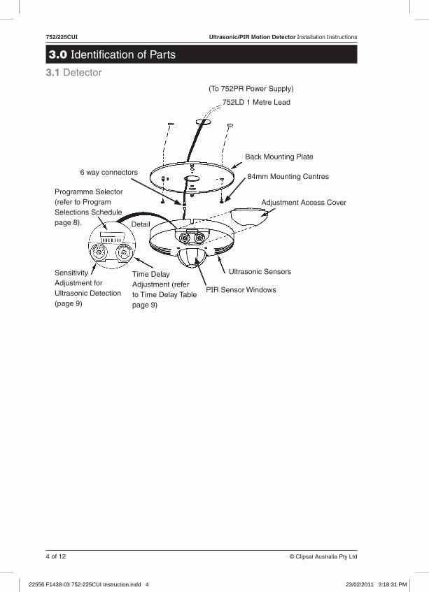
Programme Selector (refer to Program Selections Schedule page 8).
Sensitivity Adjustment for Ultrasonic Detection (page 9)
Detail
Time Delay Adjustment (refer to Time Delay Table page 9)
752LD 1 Metre Lead
(To 752PR Power Supply)
Back Mounting Plate
Adjustment Access Cover
84mm Mounting Centres
Ultrasonic Sensors
PIR Sensor Windows
6 way connectors
3.0 Identification of Parts
3.1 Detector
22556 F1438-03 752-225CUI Instruction.indd 4 23/02/2011 3:18:31 PM
5 of 12© Clipsal Australia Pty Ltd
752/225CUI Ultrasonic/PIR Motion Detector Installation Instructions
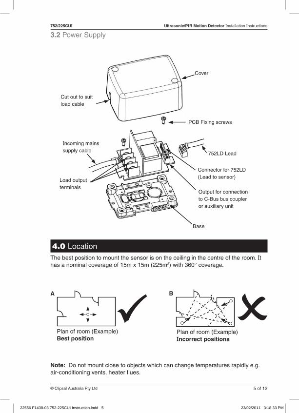
3.2 Power Supply
Cover
Cut out to suit load cable
PCB Fixing screws
752LD Lead
Connector for 752LD (Lead to sensor)
Output for connection to C-Bus bus coupler or auxiliary unit
Base
Load output terminals
Note: Do not mount close to objects which can change temperatures rapidly e.g. air-conditioning vents, heater flues.
Plan of room (Example)Incorrect positions
Plan of room (Example) Best position
A B
4.0 LocationThe best position to mount the sensor is on the ceiling in the centre of the room. It has a nominal coverage of 15m x 15m (225m2) with 360° coverage.
Incoming mains supply cable
22556 F1438-03 752-225CUI Instruction.indd 5 23/02/2011 3:18:33 PM
6 of 12
752/225CUI Ultrasonic/PIR Motion Detector Installation Instructions
© Clipsal Australia Pty Ltd
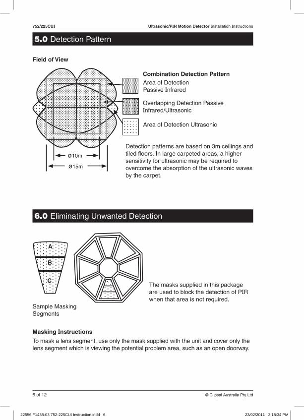
Masking Instructions
To mask a lens segment, use only the mask supplied with the unit and cover only the lens segment which is viewing the potential problem area, such as an open doorway.
Field of View
Combination Detection PatternArea of Detection Passive Infrared
Overlapping Detection Passive Infrared/Ultrasonic
Area of Detection Ultrasonic
A
B
CThe masks supplied in this package are used to block the detection of PIR when that area is not required.
Sample Masking Segments
ø15m
ø10m
5.0 Detection Pattern
Detection patterns are based on 3m ceilings and tiled floors. In large carpeted areas, a higher sensitivity for ultrasonic may be required to overcome the absorption of the ultrasonic waves by the carpet.
6.0 Eliminating Unwanted Detection
22556 F1438-03 752-225CUI Instruction.indd 6 23/02/2011 3:18:34 PM
7 of 12© Clipsal Australia Pty Ltd
752/225CUI Ultrasonic/PIR Motion Detector Installation Instructions
7.0 Mounting Procedure1. Fit power supply in ceiling space within 1m of sensor position. (Fit surface mount
socket or similar for supply from lighting circuit.)
a. Fix base of power supply to beam.
b. Fix PCB to base using screws provided.
c. Fit 752LD (1m lead) to connector on PCB at extra low voltage end.
d. Fit load cables to terminals on PCB, stripped to length as shown.
e. Cut out cover as required to suit load cables.
f. Screw cover to base.
2. Fit sensor to ceiling in (a predetermined) position.
a. Fix mounting flange to ceiling.
b. Cut hole for 752LD lead cable (Ø20mm hole).
c. Fit 752LD lead to sensor.
d. Fix sensor to mounting flange and secure using side fixing screws.
20 9
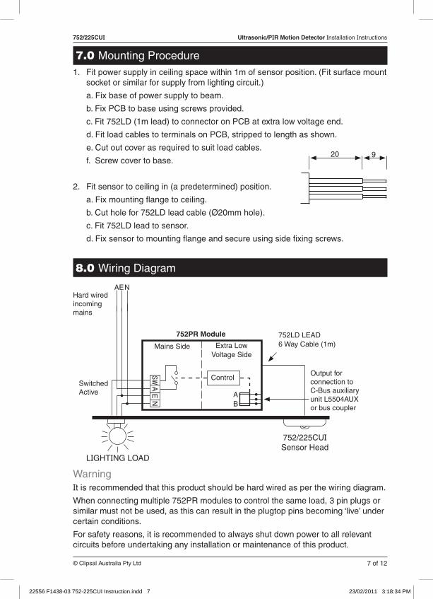
8.0 Wiring Diagram
WarningIt is recommended that this product should be hard wired as per the wiring diagram.
When connecting multiple 752PR modules to control the same load, 3 pin plugs or similar must not be used, as this can result in the plugtop pins becoming ‘live’ under certain conditions.
For safety reasons, it is recommended to always shut down power to all relevant circuits before undertaking any installation or maintenance of this product.
Extra Low Voltage Side
Hard wired incoming mains
AEN
752PR Module
Mains Side
Output for connection to C-Bus auxiliary unit L5504AUX or bus coupler
LIGHTING LOAD
752/225CUISensor Head
EA
SWN
752LD LEAD6 Way Cable (1m)
ControlSwitched Active A
B
22556 F1438-03 752-225CUI Instruction.indd 7 23/02/2011 3:18:34 PM

8 of 12
752/225CUI Ultrasonic/PIR Motion Detector Installation Instructions
© Clipsal Australia Pty Ltd
9.0 CommissioningOnce power has been installed, determine which program selection schedule best suits the application.
Program Selections Schedule
#1 PROGRAM SELECTION is used in common office areas. Multi-sensor application using this program selection will enhance the detection that is needed in partitioned office areas.
Note: This program uses only ultrasonic detection.
#2 PROGRAM SELECTION is used in areas in which turbulence, such as air draft or high air flow, is a problem.
Note: a) This program uses only passive infrared detection.
b) If environmental conditions are too severe for this program selection, use program selection #5 instead.
#3 PROGRAM SELECTION is used in areas in which high sensitivity is needed and no turbulence or adverse environmental conditions exist.
Note: This program selection permits maximum sensitivity for dual sensor technology.
#4 PROGRAM SELECTION is used in rooms and areas that demand high sensitivity once the room has been occupied, but cannot be falsely triggered by the high turbulence, (hanging mobiles, etc.) such as in classrooms.
Note: Sensitivity increases after lights are switched on.
#5 PROGRAM SELECTION is used in areas where turbulent conditions exist in which no other program selection can satisfy.
Note: This program selection requires both ultrasonic and passive infrared detection simultaneously to occur in order to trigger the timing circuit that will ultimately keep the lights on.
1 2 3 4 5 6 7
PROGRAM #1 1,4 ONLY 'ON'
ULTRASONIC DETECTION ONLY
1 2 3 4 5 6 7
PROGRAM #2 2,4 ONLY 'ON'
PIR DETECTION ONLY
1 2 3 4 5 6 7
PROGRAM #3 1,2,4 ONLY 'ON'
ULTRASONIC OR PIR DETECTION ONLY
PROGRAM #4 1,2,3 ONLY 'ON'
1 2 3 4 5 6 7
ULTRASONIC OR PIR TO ACTIVATEEITHER ULTRASONIC OR PIR WILL
KEEP LIGHTS ON
1 2 3 4 5 6 7
PROGRAM #5 1,2 ONLY 'ON'
ULTRASONIC AND PIR DETECTION
22556 F1438-03 752-225CUI Instruction.indd 8 23/02/2011 3:18:34 PM
9 of 12© Clipsal Australia Pty Ltd
752/225CUI Ultrasonic/PIR Motion Detector Installation Instructions
9.1 Time Delay TableSet the timer delay to suit, as per the table below:
Example of timer settings in minutes
Stock Room = #15Hallway = #10Restroom = # 7Office = # 8Classroom = # 9
Note: For areas larger than 10m2, set timer adjustment to #5 and perform walk testing using the actual light fixtures. After the walk testing is completed, set timer adjustment to #15.
Note: When logic key or paper clip is inserted into the slot, lights will always be on. There is no shock hazard present when using a logic key or a paper clip.
This bypass function is for emergency use only.
9.2 Approximate Sensitivity AdjustmentSet sensitivity adjustment to suit as per size of the room, shown below:
Ultrasonic detection
10m2 room = #127m2 room = #246m2 room = #365m2 room = #483m2 room = #593m2 room = #6
Note: When making adjustments do not attempt to force adjustment screws past limits.
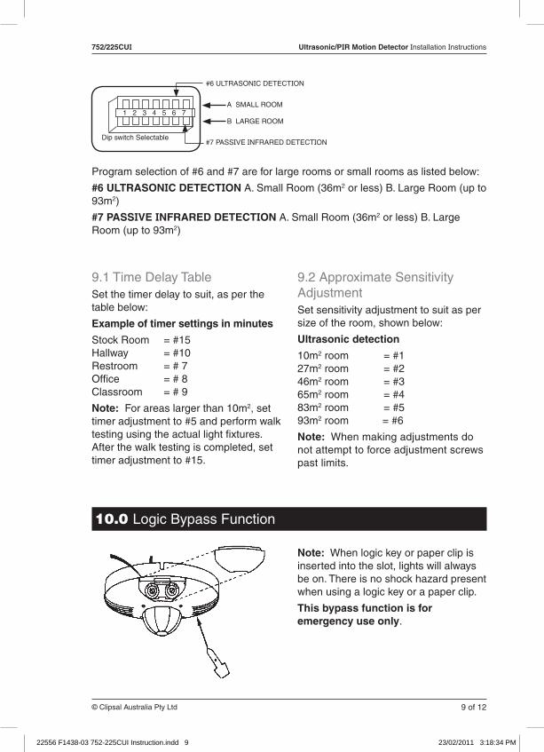
Program selection of #6 and #7 are for large rooms or small rooms as listed below:
#6 ULTRASONIC DETECTION A. Small Room (36m2 or less) B. Large Room (up to 93m2)
#7 PASSIVE INFRARED DETECTION A. Small Room (36m2 or less) B. Large Room (up to 93m2)
1 2 3 4 5 6 7
Dip switch Selectable
#6 ULTRASONIC DETECTION
A SMALL ROOM
B LARGE ROOM
#7 PASSIVE INFRARED DETECTION
10.0 Logic Bypass Function
22556 F1438-03 752-225CUI Instruction.indd 9 23/02/2011 3:18:34 PM
10 of 12
752/225CUI Ultrasonic/PIR Motion Detector Installation Instructions
© Clipsal Australia Pty Ltd
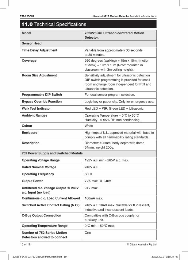
11.0 Technical Specifications
Model 752/225CUI Ultrasonic/Infrared Motion Detector.
Sensor Head
Time Delay Adjustment Variable from approximately 30 seconds to 30 minutes.
Coverage 360 degrees (walking) = 15m x 15m, (motion at desk) = 10m x 10m (Note: mounted in classroom with 3m ceiling height).
Room Size Adjustment Sensitivity adjustment for ultrasonic detection DIP switch programming is provided for small room and large room independent for PIR and ultrasonic detection.
Programmable DIP Switch For dual sensor program selection.
Bypass Override Function Logic key or paper clip. Only for emergency use.
Walk Test Indicator Red LED = PIR; Green LED = Ultrasonic.
Ambient Ranges Operating Temperature = 0°C to 50°C Humidity - 0-95% RH non-condensing.
Colour White
Enclosure High-impact U.L. approved material with base to comply with all flammability rating standards.
Description Diameter: 125mm, body depth with dome 64mm, weight 200g.
752 Power Supply and Switched Module
Operating Voltage Range 192V a.c. min.- 265V a.c. max.
Rated Nominal Voltage 240V a.c.
Operating Frequency 50Hz
Output Power 7VA max. @ 240V
Unfiltered d.c. Voltage Output @ 240V a.c. Input (no load)
24V max.
Continuous d.c. Load Current Allowed 100mA max.
Switched Active Contact Rating (N.O.) 240V a.c. 10AX max. Suitable for fluorescent, inductive and incandescent loads.
C-Bus Output Connection Compatible with C-Bus bus coupler or auxiliary unit.
Operating Temperature Range 0°C min. - 50°C max.
Number of 752 Series Motion Detectors allowed to connect
One
22556 F1438-03 752-225CUI Instruction.indd 10 23/02/2011 3:18:34 PM
11 of 12© Clipsal Australia Pty Ltd
752/225CUI Ultrasonic/PIR Motion Detector Installation Instructions
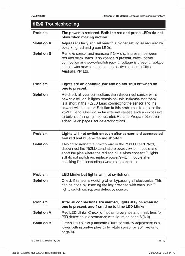
12.0 Troubleshooting
Problem The power is restored. Both the red and green LEDs do not blink when making motion.
Solution A Adjust sensitivity and set level to a higher setting as required by observing red and green LEDs.
Solution B Remove sensor and measure if 24V d.c. is present between red and black leads. If no voltage is present, check power connection and power/switch pack. If voltage is present, replace sensor with new one and send defective sensor to Clipsal Australia Pty Ltd.
Problem Lights are on continuously and do not shut off when no one is present.
Solution Re-check all your connections then disconnect sensor while power is still on. If lights remain on, this indicates that there is a short in the 752LD Lead connecting the sensor and the power/switch module. Solution to this problem is to replace the 752LD Lead. Check also for external causes such as excessive turbulence (hanging mobiles, etc). Refer to Program Selection schedule on page 8 for detector options.
Problem Lights will not switch on even after sensor is disconnected and red and blue wires are shorted.
Solution This could indicate a broken wire in the 752LD Lead. Next, disconnect the 752LD Lead at the power/switch module and short the pins where the red and blue wires connect. If lights still do not switch on, replace power/switch module after checking if all connections were made correctly.
Problem LED blinks but lights will not switch on.
Solution Check if sensor is working when bypassing all electronics. This can be done by inserting the key provided with each unit. If lights switch on, replace defective sensor.
Problem After all connections are verified, lights stay on when no one is present, and from time to time LED blinks.
Solution A Red LED blinks. Check for hot air turbulence and mask lens for PIR detection in accordance with figure on page 6 (6.0).
Solution B Green LED blinks (ultrasonic). Turn sensitivity adjustment to a lower setting and/or physically rotate sensor by 90o. (Refer to page 8).
22556 F1438-03 752-225CUI Instruction.indd 11 23/02/2011 3:18:34 PM

CLIPCOM 22556 February 2011F1438/03 10339241
Clipsal Australia Pty Ltd reserves the right to change specifications, modify designs and discontinue items without incurring obligation and whilst every effort is made to ensure that descriptions, specifications and other information in this catalogue are correct, no warranty is given in respect thereof and the company shall not be liable for any error therein.
© Clipsal Australia Pty Ltd. The identified trademarks and copyrights are the property of Clipsal Australia Pty Ltd unless otherwise noted.
Clipsal Australia Pty LtdA member of Schneider Electric
Contact us: clipsal.com/feedback
National Customer Care Enquiries:
Tel 1300 2025 25 Fax 1300 2025 56
clipsal.com
13.0 Warranty1) The benefits conferred herein are in addition to, and in no way shall be deemed to derogate; either expressly or by implication, any or all other rights and remedies in respect to Clipsal Product, which the consumer has under the Commonwealth Trade Practices Act or any other similar State or Territory Laws.
2) The warrantor is Clipsal Australia Pty Ltd of 33-37 Port Wakefield Road, Gepps Cross, SA 5094. With registered offices in all Australian States.
3) This Clipsal Product is guaranteed against faulty workmanship and materials for a period of two (2) years from the date of installation.
4) Clipsal Australia Pty Ltd reserves the right, at its discretion, to either repair free of parts and labour charges, replace or offer refund in respect to any article found to be faulty due to materials, parts or workmanship.
5) This warranty is expressly subject to the Clipsal Product being installed, wired, tested, operated and used in accordance with the manufacturer’s instructions.
6) All costs of a claim shall be met by Clipsal Australia Pty Ltd, however should the product that is the subject of the claim be found to be in good working order, all such costs shall be met by the claimant.
7) When making a claim, the consumer shall forward the Clipsal Product to the nearest office of Clipsal Australia Pty Ltd with adequate particulars of the defect within 28 days of the fault occurring. The product should be returned securely packed, complete with details of the date and place of purchase, description of load, and circumstances of malfunction.
For all warranty enquiries, contact your local Clipsal sales representative. The address and contact number of your nearest Clipsal Australia office can be found at http://www.clipsal.com/locations
22556 F1438-03 752-225CUI Instruction.indd 12 23/02/2011 3:18:34 PM