![Dynamic Line-by-line Pulse Shaping - JILA Science · 3 Dynamic line-by-line pulse shaping ... line-by-line pulse shaper with 357 MHz resolution [12], corresponding to a resolving](https://static.fdocuments.in/doc/165x107/5acffcfb7f8b9aca598d1d6a/dynamic-line-by-line-pulse-shaping-jila-science-dynamic-line-by-line-pulse-shaping.jpg)
Ultrashort Optical Pulse Shaping - National Tsing Hua...
89
IPT544000 Selected Topics in Ultrafast Optics Ultrashort Optical Pulse Shaping Chen Bin (Robin) Huang Chen-Bin (Robin) Huang Institute of Photonics Technologies National Tsing Hua University, Taiwan Various slides selected from invited talks by Prof. Andrew M. Weiner at Purdue University under permission
Transcript of Ultrashort Optical Pulse Shaping - National Tsing Hua...

IPT544000 Selected Topics in Ultrafast Optics
Ultrashort Optical Pulse Shaping
Chen Bin (Robin) HuangChen-Bin (Robin) Huang
Institute of Photonics Technologies
National Tsing Hua University, Taiwang y,
Various slides selected from invited talks by Prof. Andrew M. Weiner at Purdue University under permission

Outline
Pulse shaping basics System issues System issues Pulse shaper theory Programmable pulse shaping using liquid crystal modulators
Group-of-line regime Line-by-line regime
Other pulse shaping approaches Other pulse shaping approaches Direct space-to-time shaping Acousto-optic modulators Time lens shaping Deformable mirrors
Applications Applications
2
Shaping basicsShaping basics
3

Linear filtering
convolution
4

Femtosecond waveform synthesis
Fourier synthesis: parallel spatial/spectral modulation Diverse applications: optical communications, coherent controls,…. Pulse width range from ns to below 10 fs
Pulse shaping: control of time-domain envelope function
Spatial LightModulator/ Mask
5

Pulse shaping tutorial
k
kmtjkta ]exp[)(
0~
Phase
0~
0 mtime
doesn’tmatter
Amplitudecontrol
0~
In Phase
tens
ity
0~
0 mm
timein Phase
control
60~

Shaping data
Temporal analogy to Young’s double slit (fixed mask) Highly temporal structure by simple spectral phase and
amplitude control
2 6 THz2.6 THz
Time window
7

Synthesis of femtosecond square waves
Using fixed grey-level lithographically defined mask
How to generate gray level amplitude control?How to generate gray-level amplitude control?
Ripple:truncated spectrum
8

Shaping using spectral phase control
Inherently no loss!
9

Phase-only filtering
period: fburst duration: f
O-CDMAO CDMA
10

Selected chronology of F-T shaping
11

Selected chronology of F-T shaping (cont.)
12
Line-by-line shaping and lots more ongoing projects since 2005!!

System issuesSystem issues
13

Control strategies
Open loop vs. adaptive control
14

Adaptive pulse shaping
Interferometric intensity autocorrelation Monitoring for maximum SHG yield
15

Pulse shaping in amplified systems
16

SLM
Pulse shaper theoryW ill f d t il d i ti tiWe will perform detailed investigations
over the 4-f shaper
17

Pulse shaping theory: basics
Linear filtering system: infinite resolution
18

Pulse shaping theory: diffractions
Spectral smearing due to finite beam size
)()( xGxM
19

Waveform complexity
Bandwidth vs. minimum duration
Complexity: =B/df=T/tHigher complexity: larger beamHigher complexity: larger beam,
more dispersive grating, shorter input pulse
20

Phase to amplitude conversion
Due to diffraction
21
We will see a more evident example later
Programmable shaping:Liquid crystal modulator pulse shaping
Group-of-line regime
22

Liquid crystal array
Phase or amplitude control
in
LCM
out )(Vj yeEE Why LCM
23
ininout
yeEE Why LCMy-oriented?
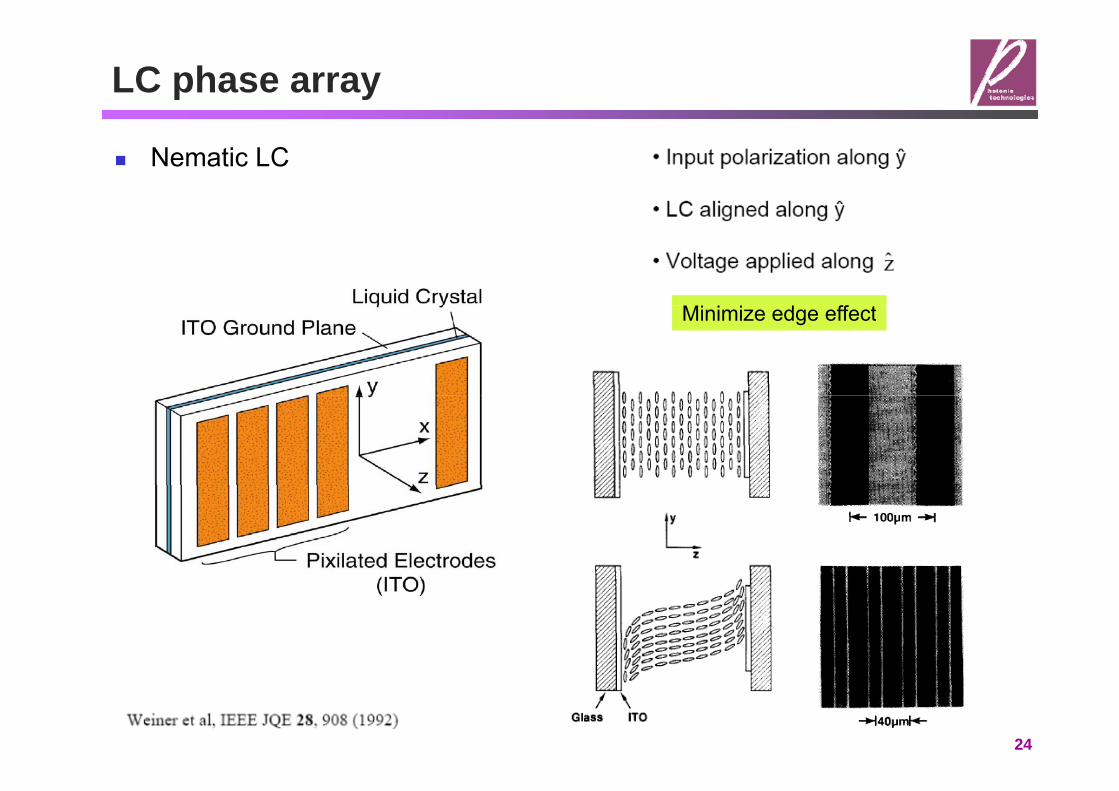
LC phase array
Nematic LC
Mi i i d ff tMinimize edge effect
24

Shaping: Group-of-Lines
Past: Group-of-Lines
25

“Dynamic” phase shaping
Limited to LC response time (~ 10 ms)
20 Hz rate switching
Question: how to generate pulse doublet?
26Weiner, Leaird, Patel, Wullert, Opt. Lett. 15, 326 (1990)
Question: how to generate pulse doublet?

Dispersion compensation
Approximate dispersion compensated using SMF and DCF For fs applications, dispersion and dispersion slope must be matched Fine-tuning as spectral phase equalizer
27

Higher-order phase correction
Mainly cubic
28

Spectral phase of 400 fs, 10-km experiment
Evident quadratic and cubic phase Can be compensated simultaneously
Modulo of 2
29

Post compensation of CPA system
30

{Phase + Amplitude} Shaping using LCM
2 orthogonal LC layers
iny
inxVVj
outy
outx
EE
jj
eEE
)cos()sin()sin()cos(),( 21
)]()([21
2211 VV )]()([21
2211 VV
Linear polarized input + output polarizer
xVVeEE VVjinout ˆ)],(cos[ 21),( 21
31
phase amplitude

{Phase + Amplitude} shaping examples
Nearly arbitrary pulses
Time-window
32
Question: how to generate these waveforms?
LCM shaping summary: Group-of-line
Gray-level amplitude and phase control Pixellated spatial modulation (128, 512, 640, more than 10,000) Quasi-static mask Reprogramming time~ 10 ms or greater
Low attenuation Low attenuation Phase and amplitude response needs calibration Time window that limits waveform spaceTime window that limits waveform space
33

Programmable shaping:Liquid crystal modulator pulse shaping
Line-by-line regimeLine by line regime
2222
22
)2
exp()(in
a
wttg
Increase spectral resolution
)0(cos2ln2
i
inwin cd
wT
Increase spectral resolution increase time window
34

Line-by-line shaper Reflective grating based shaper
f f
1200
LCM
f f~1000 mm focal length
1200 lines/mm Grating
Lens1542.6 1542.7 1542.8
Wavelength (nm)
2.6 GHz
MirrorLens
CollimatorTelescope 2 1
Circulator~18 mm diameter b Input Combs
Polarization Controller
p 2 1
3
beam
Polarizer
Input Combs{5,9,10}-GHz
1pixel{4.5, 5}-GHz
Output shaped pulse
35

Shaping: Line-by-line
Line-by-Line
Jiang, Seo, Leaird, Weiner, Opt. Lett. 30, 1557 (2005).
y• Overlapped waveforms• Step closer to true optical arbitrary
(O AWG){Pulse shaping} + {Combs}
waveform generation (O-AWG)frep
• Increase shaper resolution
frequency
• Increase shaper resolution• Increase comb spacing
New physical insight:Shaped waveforms are sensitive to
T/2
Shaped waveforms are sensitive to comb offset frequency drifts!
timeT=1/frep0
36

Sensitive to comb offset shifts
Comb-offset frequency fluctuates
Time-domain view fluctuates
2 lines of a harmonically mode-locked Er-fiber [email protected] GHz
Phase between pulses
Multiple tracesof OSA
frep
Phase between pulsesfluctuates
Frequency (GHz)0 20
of OSAOverlapped intensity fluctuates
=0
-2 -1 0 1 2
t/T
Maximum
noise
37
t/T

Filter function: H()1
dxexMw
H wx
20
2)(221
20
)(2)(
Huang, Jiang, Leaird, Weiner, Opt. Express 14, 13164 (2006)
Frequency-domain view
10
0
(dB
) ExpSim
=0
30
-20
-10
|H(
)|2(
=0Sim
Frequency (GHz)-20 -10 0 10 20-30
= Frequency discriminator
0
dB)
Exp
= Frequency discriminator
-20
-10=
H(
)|2(d
pSim
38
-20 -10 0 10 20-30
Frequency (GHz)
|H

Correlating Two Pictures Intensity variance due to
Freq-domain: H() discriminatorTime domain: delay Time-domain: delay
=0===3=H()( )=0=25%=50%
Frequency-Domain
2( f )Time
2
)(
cos2(frept)
=0)
Time-Domain
39
=25%=50%
Why repetition change!

Waveforms for sensitive monitoring 2 lines spaced by 2frep
Frequency vs. time-domain viewCan be extended to Nf
Periodicity conversion Can be extended to Nfrep
0 1-1-2 2 1
0
0.5
Pow
er
rep
T/21
f/frep
-2 -1 0 1 20
0.5
1
Inte
nsity
-1 -0.5 0 0.5 10
t/T
I
40
R()≡I(0)/I(T/2)These observations were experimental verified

Question
So, if we don’t have time window, but we still have phase to intensity conversionbut we still have phase-to-intensity conversion,
where are the diffracted energy?
41

Comb source alternatives Self-referenced mode-locked lasers
Highest frequency stabilityN t il bl t ffi i tl hi h t ( til tl ) Not available at sufficiently high rates (until recently)
Pulse shapers with higher resolution spectral dispersers? Filter to increase comb spacing (NIST, MIT..) parameter mismatch
Hybrid mode-locked lasersP f t bilit l k f ff t f t i bilit Poor frequency stability, or lack of easy offset frequency tuning ability
Phase-modulated CW sources Phase modulated CW sources Moderate frequency stability Easy tuning of offset frequency
Li it d ti l b d idth ( b h d b li ti )
(enabled experimental tests of pulse shape changes due to comb offsets)
Limited optical bandwidth (may be enhanced by nonlinear propagation)
42
Broad BW, frequency stable

Source alternative: PMCW
Phase-Modulated Continuous-Wave laser frequency comb =Vp/Vmodulation index
V cos( t))}cos(exp{)( 0
0 tjeEtE reptj
Vpcos(rept)
})(exp{)( 0 tmjJ repm
m
modulationBessel’s
0.49GHz comb@2V
frequencyesse sseries
Benefits:
0
0.2
d (a
.u.)
Benefits:Relative high frequency stability
No stabilization required!Ease of tuning
-0.2
0
Fiel
d
Disadvantage:Dispersion control required
Linewidth
43
-50 0 50-0.4
Frequency (GHz)
LinewidthPulse shape

10-GHz PMCW comb: Setup
0 0
IM LCM Dual-modulation Broader bandwidth, shorter pulse
-20
-10
(dB
m)
0
20
-10
0
PM RF
-40
-30
Spec
trum
-40
-30
-20
~7dB intensityi ti
PM
0
{Phase + Amplitude} control to 41 lines1541 1542 1543 1544
-50
Wavelength (nm)1540.5 1542 1544-50
40
Wavelength (nm)
variation
-20
-10
m (d
B)
-40
-30
Spec
trum
ExperimentalSuper-Gaussian
44
1540.5 1542 1544-50
Wavelength (nm)Huang, Jiang, Leaird, Weiner, Electron. Lett. 42, 1114 (2006).

High-rate pulse train generation
Phase correction Automated process
Intensity autocorrelation
22
)()()(
tItIG
Nonlinear pulse propagation Adiabatic soliton compression
22)(
)(tI
Dispersion-decreasing fiberPMCW -10
0-10
0
(dB
) 298 fs
seed pulses
D(0) D(L)
1520 1530 1540 1550 1560 1570-40
-30
-20dB
40
-30
-20
SHG
(45
1520 1530 1540 1550 1560 1570Wavelength (nm)
-60 0 60-40(ps)
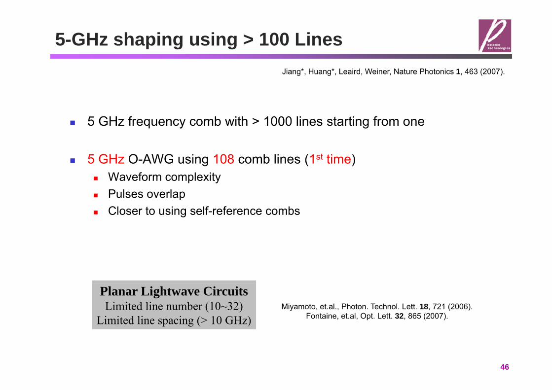
5-GHz shaping using > 100 LinesJiang*, Huang*, Leaird, Weiner, Nature Photonics 1, 463 (2007).
5 GHz frequency comb with > 1000 lines starting from one
5 GHz O-AWG using 108 comb lines (1st time) Waveform complexity Pulses overlap Pulses overlap Closer to using self-reference combs
Planar Lightwave CircuitsLimited line number (10~32)
Limited line spacing (> 10 GHz)Miyamoto, et.al., Photon. Technol. Lett. 18, 721 (2006).
Fontaine, et.al, Opt. Lett. 32, 865 (2007).
46

Setup > 1000 lines comb generation through soliton compression
Adiabatic soliton compressionDispersion-decreasing fiberp g
Auto-correlationse)
270 fs
Line
ar
ar S
cale
B/di
v) 1 THz Input CW
-10 0 10
div
ty (
Line
Time (ps)-5 5
ity (1
0 dB
#1#1000
-200 -150 -100 -50 0Time (ps)
10 d
B/d
Inte
nsit
Inte
ns
1525 1525 5 1564 5 1565
47Time (ps)
-200 -150 0-50-100
Time (ps)
1520 1530 1540 1550 1560 1570Wavelength (nm)
1525 1525.5 1564.5 1565

> 100 lines shaping examples-(1)
Linear phase ramp delay of pulse locations Delay across entire period hallmark of line-by-line shaping
48

> 100 lines shaping examples-(2)
O-AWG using intensity/phase over 108 lines
Cross-correlation
.)
0
ensi
ty (
a.u
Inte
1536 1537 1538 1539 15400
Wavelength (nm)1535
49

Line-by-line shaping summary
Line-by-line shaping removes the time-window limitation!Comb frequency stability shows up in shaped waveform intensity noise Comb frequency stability shows up in shaped waveform intensity noise Time and frequency domain views “Quiet” and large spacing combs preferred
Allows optical arbitrary waveform generations
50

Other pulse shaping:Direct space-to-time shaping
grating 4-f shaper
51

DST shaping
Output temporal profile a directly scaled version of input spatial mask Changing slit-lens distance: frequency modulation without affecting time-
domain profiledomain profile Space (parallel) Time (serial) processing
52

DST shaping data
53

Shifting center frequency
Sliding slit location Why amplitude variations?
]'exp[)()()(ˆ
txjtstate a
out
54
1. What happens if we move the slit off the focal plane?2. What if radius of beam not infinite?
Other pulse shaping:Acousto-optic modulator
Photo-elastic effect: RFPZT acoustic wave index grating (=v/)
55

AOM shaping
Spectral amplitude and phase control via diffraction off the AO crystal Requires electrical driving signal Limited response time, suitable for amplified systems
t
v~105 cm/s for TeO2
)()()(AO
AOinouttstete
Selected from long pulse sequence
56

Frequency swept pulses
Hyperbolic tangent frequency sweep
)h()()(
)(sech)( )1(
ttte i
)tanh()()( tt
t
Spectrally/temporally resolved up conversionp y p y p
57

AOM shaping summary
Independent gray-level amplitude and phase control Continuous spatial modulation (time-bandwidth product > 1000) Travelling-wave mask Reprogramming time~10 s
High attenuation High attenuation Acoustic attenuation must be calibrated Complex electrical functions neededComplex electrical functions needed
58

Oth l h iOther pulse shaping:Chirp processing
)()()(2jkx
Space-Time duality
)2
exp()()(
2jtz
jxsxs inout
59
)2
exp()()(2z
jttata inout

Direct frequency-to-time shaping
Frequency-dependent time delay Large dispersion regime
)()(
)()( 2 2
2
tAejzta ztj
)(2
),(22
2
zAe
zzta
60

Arbitrary mmw generations
~90 ps/nm
1 25G 2 5G 5G
Time-aperture: optical bandwidthDispersion: sign of chirp
1.25G 2.5G 5G
61

Fast RF waveform measurement
Reversed thinking: time frequency mapping Different temporal samples impressed onto different spectral components Resolve and detected using grating + detector array
Optical modulator
62

Other pulse shaping:Time-lens shaping
fdd imgobj
111
fimgobj
ttimgobj
)()(
11
63
gj )(2
)(2

Time microscope Analogy to spatial lens Mt=100
G t f i l h t l t!2)(
2 176.0 psobj Great for single shot pulse measurement! 2)(
2 6.17 psimg
64Bennett, Kolner, Opt. Lett. 24, 783 (1999)

Optical oscilloscope on Si chip
Time-lens concept 1 nm shift 5.2 ps shift
65
Foster et.al., Nature 456, 81 (2008).

Other pulse shaping:Movable and deformable mirrors
66

Rapid scanning optical delay line
Roughly kHz rate Optical phase and delay decoupled
Same control used for Ti:S combs!!
Time-space coupling
Same control used for Ti:S combs!!
67

Pulse compression
68

Selected applications:Communications and coherent control
69

Planar lightwave circuit shaper
Silica based devices
70

Wavelength domain multiplexing
71

Dark solitons in optical fiber
1.4 m fiber
72

Millimeter-wave generations
73

Spectral tailor of UWB
Duration: RF BWCycle: RF center frequency
74McKinney, Lin, Weiner, IEEE Trans. Microwave Theory and Tech, 54, 4247 (2006)

Rapid reprogrammable RF-AWG
Rapid switching between two waveforms 2 CW lasers
2 intensity modulators (BERT to select) 2 intensity modulators (BERT to select) Comb generator (phase modulator + line-by-line pulse shaper) 60 GHz bandwidth photo-detector Monitor optical spectrum, RF time-domain waveform, RF spectrum
-21
23-1 0
-21
23-1 0
{-2,1,2,3}=
5dB
/DIV
-3 1 31 0 -3 1 31 0
1540.8 1541.2 1541.6 15425
a b
75
Wavelength (nm)
Huang, Leaird, Weiner, Opt. Lett. 32, 3242 (2007).

10-GHz programmability results-(I)
Q=[1111 0000]
8
-4
0
-16
-12
-8Extinction
~16 dBPhase modulation
-500 0 500t (ps)
5dB
/DIV
1541 1542Wavelength (nm) Frequency modulation
(a.u
.)
(a.u
.) Ia(t) Ib(t)
nten
sity
nten
sity
5dB
/DIV
76
In
-500 0 500In
Time (ps)
1541 1542Wavelength (nm)

10-GHz programmability results-(II) Triangular waveform updates
Dual-modulation scheme Cubic spectral phase Cubic spectral phase
V a.u.
)28 lines per comb
5dB
/DIV
nten
sity
(aIn
y (a
.u.)
y (a
.u.)
Inte
nsity
Inte
nsity
77

Goal: remote MMW carrier generation
Radio-over fiber (low loss) Photonic MMW generator
Sub-ps pulses > 300 GHz repetition-rates Dispersion pre-compensation to arbitrary SMF link length Dispersion pre compensation to arbitrary SMF link length
EndArbitrary SMF length-users
MMWsignal
ti
Remote photonic MMW
t generationgenerator
78
These targets are also challenges

Remote photonic MMW generator
Phase-modulated CW laser frequency comb Line-by-line optical pulse shaper: {amplitude, phase}-controls
f(frep)-1
f
ff
LCM Lens
frep
f
Reflective line-by-line pulse shapert
( p)
Line-by-LinePulse Shaper
CWLaser
PhaseModulator
fMirror
G iSpectral
f
frepPA
(Nf )-1 Free Space
GratingSpectralLines
Collimator
TelescopeCirculator
PCInput
Polarizer
SMF
t
(Nfrep) Free SpaceFiberShaped
Output
Shi H d P NPG A i M t 3 41 (2011)
79Shi, Huang, and Pan, NPG Asia Materials 3, 41 (2011)
t Shi, Huang, and Pan, NPG Asia Mat. 3, 41 (2011)

Repetition-rate multiplication (RRM) Amplitude filtering Phase filtering
P i di h t l lf i i t l T lb t ff t Periodic phase: temporal self-imaging, temporal Talbot effect
Huang and Lai, Photon. Technol. Lett. 12, 167 (2000)2( ) s k T0
Azaña and Muriel, J. Sel. Topics Quantum Electron. 7, 728 (2001)( )k kN
0TN RRM condition
breaksSMF
Mode-lockedlaser
FBGRRM train
SMF
laser
80

Short pulse delivery: dispersion issue
Residual β3 term
Dispersion compensation fiber
SMF
Mode-locked
DCF
Mode-lockedlaser
2 332( ) [ ]L
β3 term compensated DCF + Pulse shaper
( ) [ ]2 6SMF L
β3 term compensated50 kmSMF DCF
Mode-lockedlaser
Pulseshaper
81Jiang, Yang, Leaird, and Weiner, Opt. Lett. 30, 1449 (2005)

Line-by-line pulse shaping
Jiang, Huang, Leaird, and Weiner, Nat. Photonics 1, 463 (2007)
Independent control over each comb line
( ) 2 ( )N
DCF needed?
( ) 2 ( )SMF k k rem kN Integer Talbot effect
500
600
ase
(2)
200
300
400
500
Pha
0
100
-10 0 10Line number
Severely broadened single pulseDemands high
source temporalcoherence
82
t t

Experimental results
31GHz PMCW Comb
0 ,25( ) ( ) ( )LCM rem km 0( ) ( )LCM
31GHz PMCW Comb
0 93 ps0.93 psDe-convoluted
83

Remote ultrahigh rate pulses
124GHz Shaper-RRM
π π π
0 ,25( ) ( ) ( ) ( )LCM rem RRMkm
4x-RRMPhase: 0 , 0 , π , 0
00 0 0 0
0ππ
2x-RRMPhase: 0 , π
2
00 00
π
2
π
2
π
2 π
2
2
Huang and Lai, Photon. Technol. Lett. 12, 167 (2000)
84

Impulsive stimulated Raman scattering
Single pulseexcitationPhase only shaping
85

Coherent control on TPA yield
2Asymmetric phase: no change! 200
2 )]}2
()2
([exp{ djS Asymmetric phase: no change!
Cs: 6S1/2 8 S1/2
86

Soft X-ray generation
Solid: optimizedy Solid: optimized
inte
nsity phase
87

Polarization shaping
Brixner, et.al, Appl. Phys. B 74, S133 (2002)
88Aeschlimann, et.al, Nature 446, 310 (2007)

Summary
Shaper basics F-T shaper using fixed and programmable masks
Theoretical derivations Group-of-line vs. line-by-line
Other shaping methods Other shaping methods Theoretical derivations and examples
Applications in various diverse fields
89