Ultra-Portable Greenhouse Gas Analyzer User Manual GATOS RESEARCH Ultra-Portable Greenhouse Gas...
84
LOS GATOS RESEARCH Ultra-Portable Greenhouse Gas Analyzer User Manual Model 915-0011 Los Gatos Research 67 East Evelyn Avenue, Suite 3 Mountain View, CA 94041 Phone: 650-965-7772 Fax: 650-965-7074 www.lgrinc.com Document No. 915-U011 Version 2.A Release Date 5/16/2014
Transcript of Ultra-Portable Greenhouse Gas Analyzer User Manual GATOS RESEARCH Ultra-Portable Greenhouse Gas...

LOS GATOS RESEARCH
Ultra-Portable Greenhouse Gas Analyzer
User Manual
Model 915-0011
Los Gatos Research 67 East Evelyn Avenue, Suite 3
Mountain View, CA 94041 Phone: 650-965-7772
Fax: 650-965-7074 www.lgrinc.com
Document No. 915-U011
Version 2.A Release Date 5/16/2014

Ultra Portable GGA 3
COPYRIGHT
©2013 Los Gatos Research, Inc. All rights reserved. Rights reserved under the copyright laws of the United States. RESTRICTED RIGHTS LEGEND
Use, duplication or disclosure by the United States Government is subject to restriction as set forth in subparagraph (c)(1)(ii) of the Rights in Technical Data and Computer Software clause at DFARS 252.227-7013. Notwithstanding any other license agreement that may pertain to, or accompany the delivery of, this computer software, the rights of the United States Government regarding its use, reproduction, and disclosure are as set forth in the Commercial Computer Software-Restricted Rights clause at FAR 52.227-19. TRADEMARKS
Products mentioned in this document are trademarks or registered trademarks of their respective holders.

Ultra Portable GGA 5
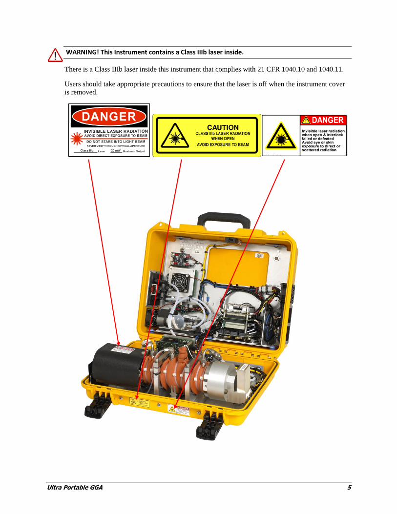
WARNING! This Instrument contains a Class IIIb laser inside.
There is a Class IIIb laser inside this instrument that complies with 21 CFR 1040.10 and 1040.11.
Users should take appropriate precautions to ensure that the laser is off when the instrument cover
is removed.

Ultra Portable GGA 7
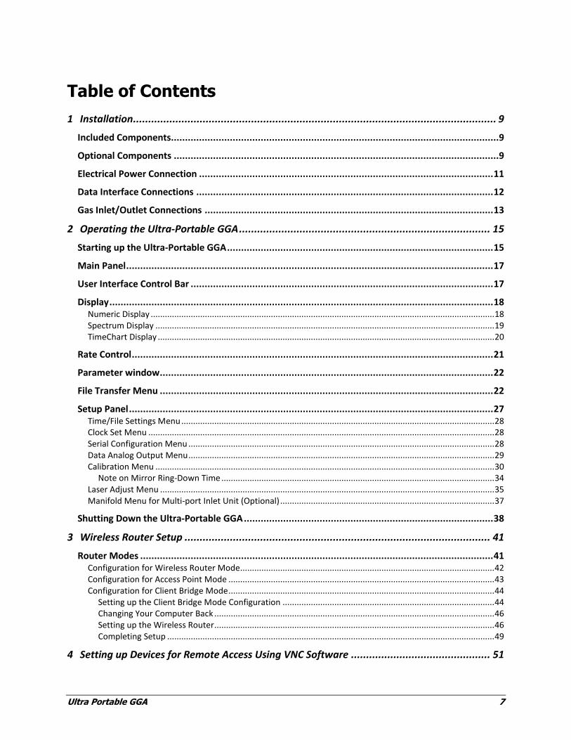
Table of Contents
1 Installation ........................................................................................................................ 9
Included Components.....................................................................................................................9
Optional Components ....................................................................................................................9
Electrical Power Connection ......................................................................................................... 11
Data Interface Connections .......................................................................................................... 12
Gas Inlet/Outlet Connections ....................................................................................................... 13
2 Operating the Ultra-Portable GGA ................................................................................... 15
Starting up the Ultra-Portable GGA ............................................................................................... 15
Main Panel ................................................................................................................................... 17
User Interface Control Bar ............................................................................................................ 17
Display ......................................................................................................................................... 18 Numeric Display .................................................................................................................................................. 18 Spectrum Display ................................................................................................................................................ 19 TimeChart Display ............................................................................................................................................... 20
Rate Control ................................................................................................................................. 21
Parameter window ....................................................................................................................... 22
File Transfer Menu ....................................................................................................................... 22
Setup Panel .................................................................................................................................. 27 Time/File Settings Menu ..................................................................................................................................... 28 Clock Set Menu ................................................................................................................................................... 28 Serial Configuration Menu .................................................................................................................................. 28 Data Analog Output Menu .................................................................................................................................. 29 Calibration Menu ................................................................................................................................................ 30
Note on Mirror Ring-Down Time .................................................................................................................... 34 Laser Adjust Menu .............................................................................................................................................. 35 Manifold Menu for Multi-port Inlet Unit (Optional) ........................................................................................... 37
Shutting Down the Ultra-Portable GGA ......................................................................................... 38
3 Wireless Router Setup ..................................................................................................... 41
Router Modes .............................................................................................................................. 41 Configuration for Wireless Router Mode............................................................................................................ 42 Configuration for Access Point Mode ................................................................................................................. 43 Configuration for Client Bridge Mode ................................................................................................................. 44
Setting up the Client Bridge Mode Configuration .......................................................................................... 44 Changing Your Computer Back ....................................................................................................................... 46 Setting up the Wireless Router ....................................................................................................................... 46 Completing Setup ........................................................................................................................................... 49
4 Setting up Devices for Remote Access Using VNC Software .............................................. 51
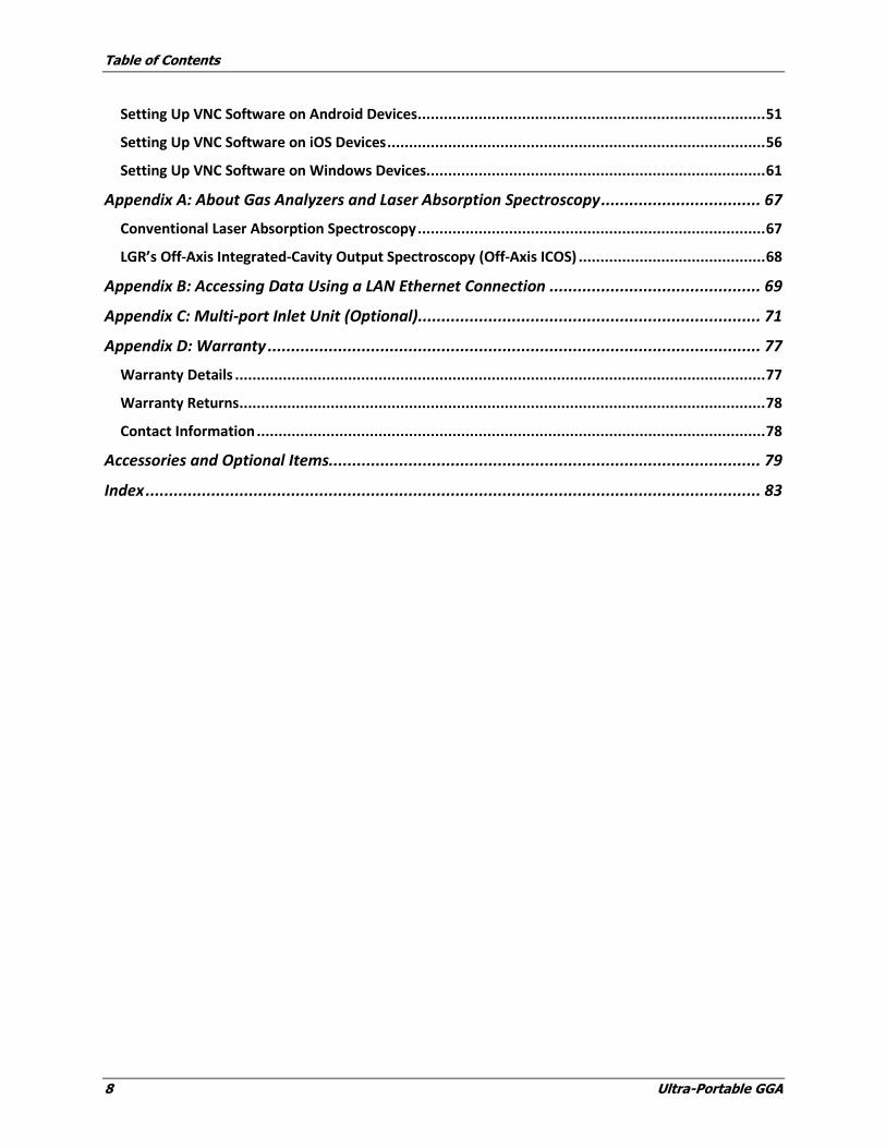
Table of Contents
8 Ultra-Portable GGA
Setting Up VNC Software on Android Devices ................................................................................ 51
Setting Up VNC Software on iOS Devices ....................................................................................... 56
Setting Up VNC Software on Windows Devices.............................................................................. 61
Appendix A: About Gas Analyzers and Laser Absorption Spectroscopy .................................. 67
Conventional Laser Absorption Spectroscopy ................................................................................ 67
LGR’s Off-Axis Integrated-Cavity Output Spectroscopy (Off-Axis ICOS) ........................................... 68
Appendix B: Accessing Data Using a LAN Ethernet Connection ............................................. 69
Appendix C: Multi-port Inlet Unit (Optional)......................................................................... 71
Appendix D: Warranty ......................................................................................................... 77
Warranty Details .......................................................................................................................... 77
Warranty Returns ......................................................................................................................... 78
Contact Information ..................................................................................................................... 78
Accessories and Optional Items............................................................................................ 79
Index ................................................................................................................................... 83
Ultra Portable GGA 9
1 Installation
Included Components
The Los Gatos Research (LGR) Ultra-Portable Greenhouse Gas Analyzer (Ultra-Portable GGA) is
comprised of several components. Be sure to check that each of the system components has arrived
before beginning the installation procedure. You should have received:
Ultra-Portable Greenhouse Gas Analyzer (Ultra-Portable GGA), Model No. 915-0011
Instrument Power Cord
AC-DC Power Supply
External In-line Filter (push-connect)
Null Modem type Serial Data Cable
USB Flash Drive
Ultra-Portable GGA Users Guide (this document)
Certificate of Compliance
If you have not received all of the above included components, please contact LGR (650-965-7772
or [email protected]).
Optional Components
See Accessories and Optional Components in the back section of this manual.
DC Power Pack, with Battery (915-9400-1200)
DC Power Case, no Battery (915-9400-0000)
Battery Hook-up Kit (915-9200-0000)
Ultra-Portable GGA Back Pack (915-9500-0000)
Wireless User Interface with iPad (915-9001-0000)
Wireless User Interface with Nexus7 tablet (915-9002-0000)
Replacement Fuses, In-line Filters, Side Covers (915-9300-0000)
Secondary AC-DC Power Supply (915-9100-0000)
Warning
The wireless user interface will not work if:
The analyzer has a system failure
The hard drive fails or is corrupted
Battery power to the analyzer is interrupted
If any of these failures occur, you will need a mouse, keyboard and monitor
to restart the analyzer. A back up hard drive is recommended.
Installation
10 Ultra-Portable GGA
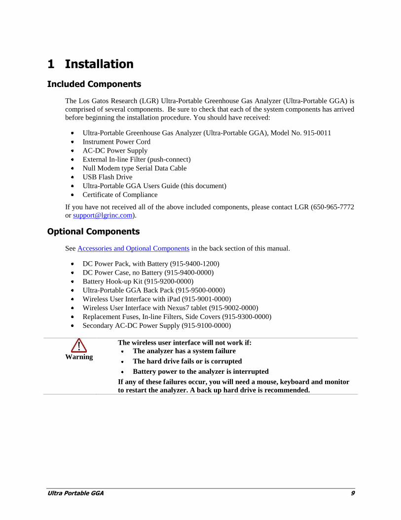
Figure 1: Ultra-Portable GGA; Left side, DC Power Entry, Gas Inlet and Exhaust connections.
Figure 2: Ultra-Portable GGA; Right Side, Data Port Connections.
DC power entry (See Detail Figure 3)
Data Port Connections, (See Figure 4)
Gas Exhaust Port (1/4” tube). (See Detail Figure 6)
Gas Inlet Port (1/4” tube) (See Detail Figure 6)
Power Switch (See Detail Figure 3)
Installation
Ultra-Portable GGA 11
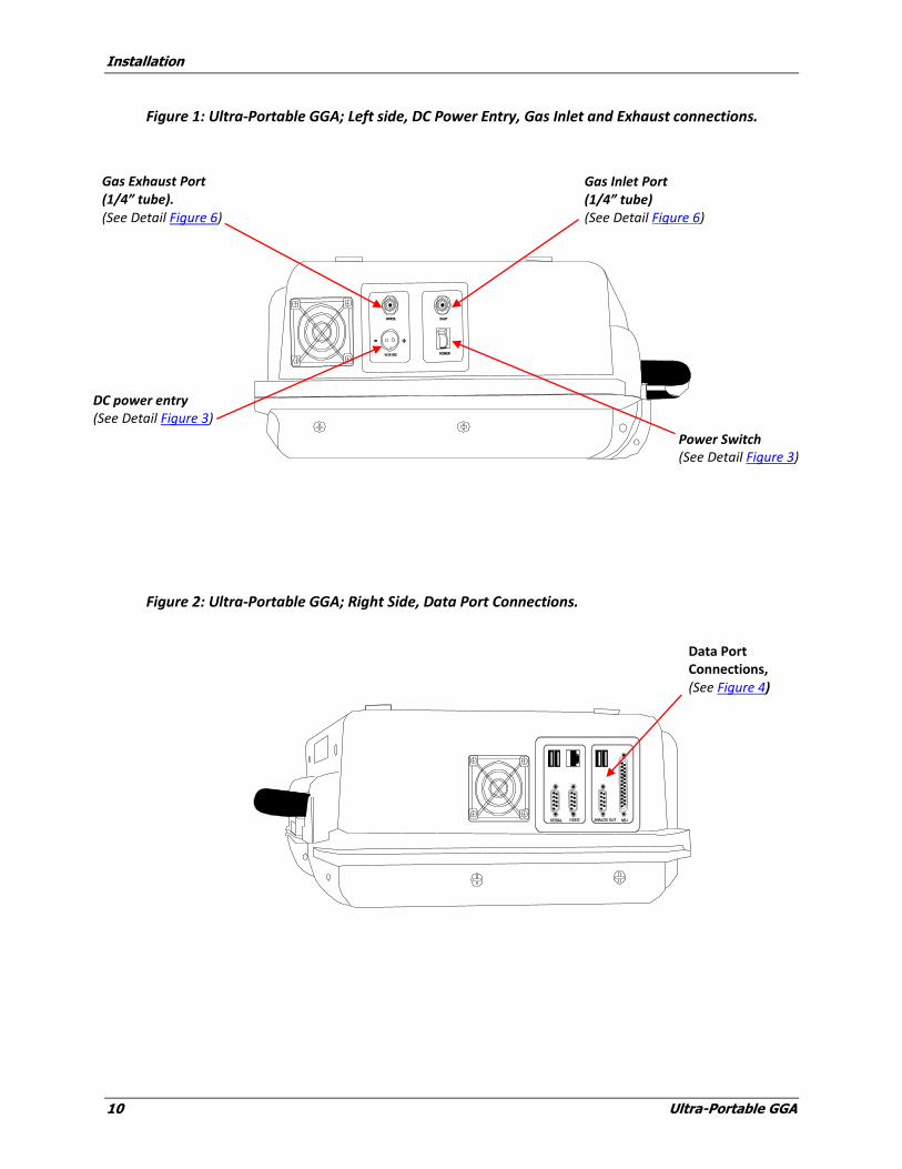
Electrical Power Connection
To operate the Ultra-Portable GGA, the AC/DC Power Supply must be connected to the power
entry port on the left side of the unit (see Figure 1 and Figure 3). Operation using an external
battery is also possible by using the Battery Hook-up Kit. The battery voltage must be in the range
of 10-30 volts DC, and has a continuous discharge rate to power 80 watts (or higher).
Figure 3: DC Power Entry module with internal fuse.
DC Power Entry Power Switch
Installation
12 Ultra-Portable GGA
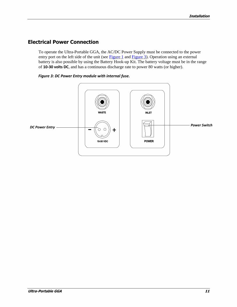
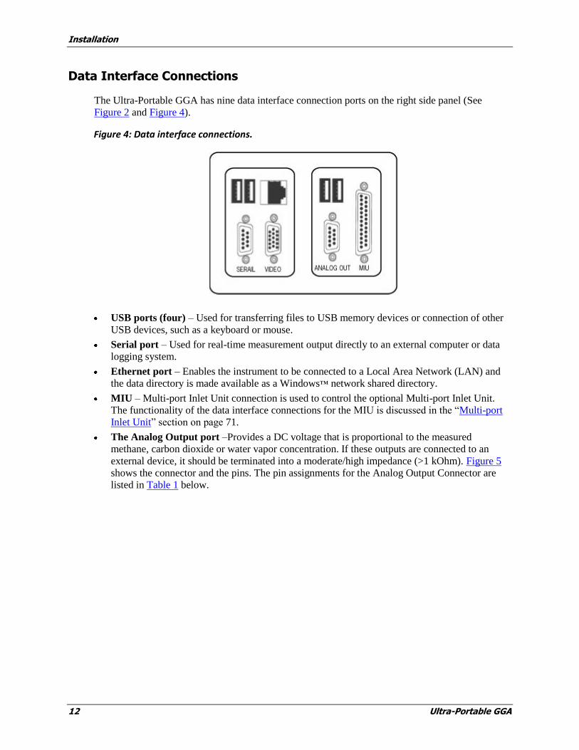
Data Interface Connections
The Ultra-Portable GGA has nine data interface connection ports on the right side panel (See
Figure 2 and Figure 4).
Figure 4: Data interface connections.
USB ports (four) – Used for transferring files to USB memory devices or connection of other
USB devices, such as a keyboard or mouse.
Serial port – Used for real-time measurement output directly to an external computer or data
logging system.
Ethernet port – Enables the instrument to be connected to a Local Area Network (LAN) and
the data directory is made available as a Windows™ network shared directory.
MIU – Multi-port Inlet Unit connection is used to control the optional Multi-port Inlet Unit.
The functionality of the data interface connections for the MIU is discussed in the “Multi-port
Inlet Unit” section on page 71.
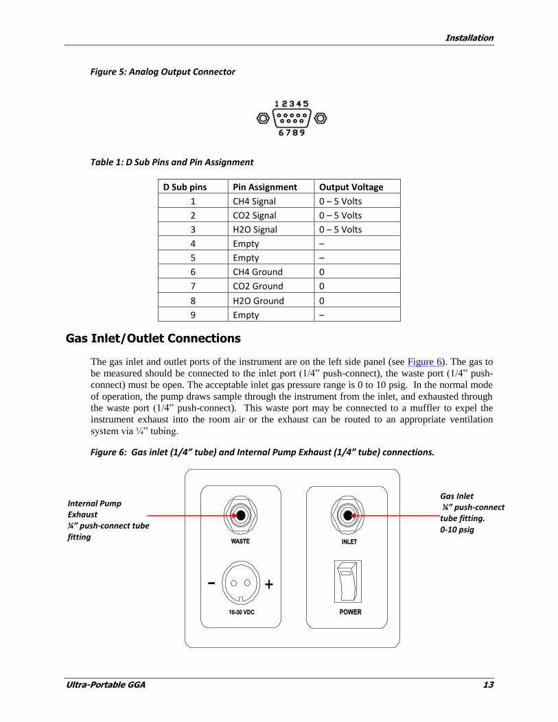
The Analog Output port –Provides a DC voltage that is proportional to the measured
methane, carbon dioxide or water vapor concentration. If these outputs are connected to an
external device, it should be terminated into a moderate/high impedance (>1 kOhm). Figure 5
shows the connector and the pins. The pin assignments for the Analog Output Connector are
listed in Table 1 below.
Installation
Ultra-Portable GGA 13
Figure 5: Analog Output Connector
Table 1: D Sub Pins and Pin Assignment
D Sub pins Pin Assignment Output Voltage
1 CH4 Signal 0 – 5 Volts
2 CO2 Signal 0 – 5 Volts
3 H2O Signal 0 – 5 Volts
4 Empty –
5 Empty –
6 CH4 Ground 0
7 CO2 Ground 0
8 H2O Ground 0
9 Empty –
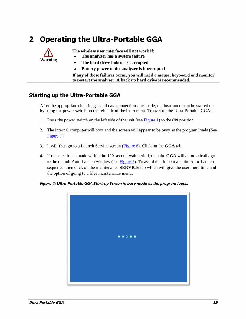
Gas Inlet/Outlet Connections
The gas inlet and outlet ports of the instrument are on the left side panel (see Figure 6). The gas to
be measured should be connected to the inlet port (1/4” push-connect), the waste port (1/4” push-
connect) must be open. The acceptable inlet gas pressure range is 0 to 10 psig. In the normal mode
of operation, the pump draws sample through the instrument from the inlet, and exhausted through
the waste port (1/4” push-connect). This waste port may be connected to a muffler to expel the
instrument exhaust into the room air or the exhaust can be routed to an appropriate ventilation
system via ¼” tubing.
Figure 6: Gas inlet (1/4” tube) and Internal Pump Exhaust (1/4” tube) connections.
Gas Inlet ¼” push-connect tube fitting. 0-10 psig
Internal Pump Exhaust ¼” push-connect tube fitting

Ultra Portable GGA 15
2 Operating the Ultra-Portable GGA
Warning
The wireless user interface will not work if:
The analyzer has a system failure
The hard drive fails or is corrupted
Battery power to the analyzer is interrupted
If any of these failures occur, you will need a mouse, keyboard and monitor
to restart the analyzer. A back up hard drive is recommended.
Starting up the Ultra-Portable GGA
After the appropriate electric, gas and data connections are made; the instrument can be started up
by using the power switch on the left side of the instrument. To start up the Ultra-Portable GGA:
1. Press the power switch on the left side of the unit (see Figure 1) to the ON position.
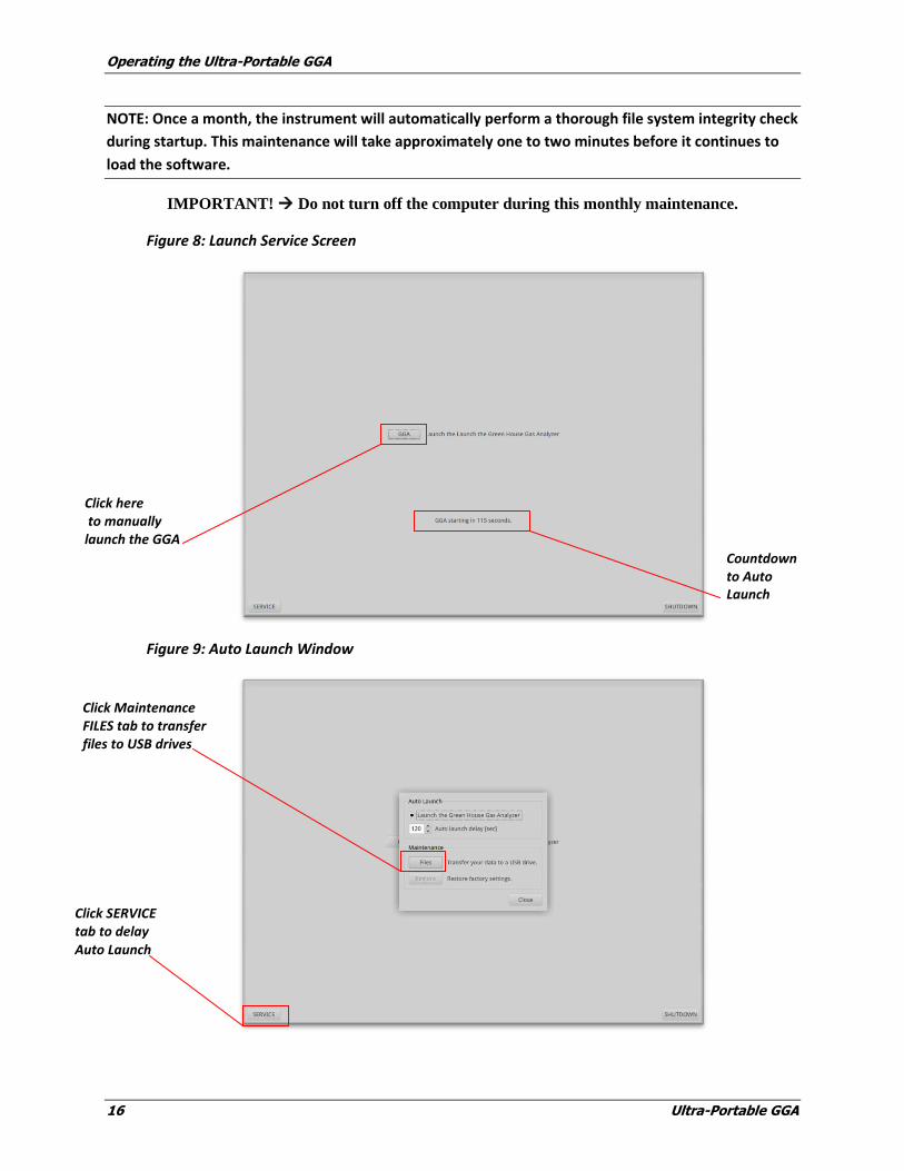
2. The internal computer will boot and the screen will appear to be busy as the program loads (See
Figure 7).
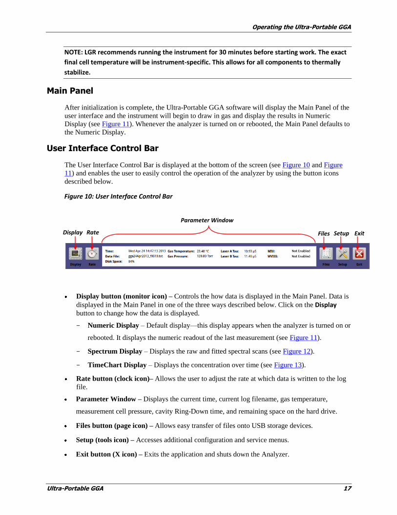
3. It will then go to a Launch Service screen (Figure 8). Click on the GGA tab.
4. If no selection is made within the 120-second wait period, then the GGA will automatically go
to the default Auto Launch window (see Figure 9). To avoid the timeout and the Auto-Launch
sequence, then click on the maintenance SERVICE tab which will give the user more time and
the option of going to a files maintenance menu.
Figure 7: Ultra-Portable GGA Start-up Screen in busy mode as the program loads.
Operating the Ultra-Portable GGA
16 Ultra-Portable GGA
NOTE: Once a month, the instrument will automatically perform a thorough file system integrity check
during startup. This maintenance will take approximately one to two minutes before it continues to
load the software.
IMPORTANT! Do not turn off the computer during this monthly maintenance.
Figure 8: Launch Service Screen
Figure 9: Auto Launch Window
Click here to manually launch the GGA
Click SERVICE tab to delay Auto Launch
Click Maintenance FILES tab to transfer files to USB drives
Countdown to Auto Launch
Operating the Ultra-Portable GGA
Ultra-Portable GGA 17
NOTE: LGR recommends running the instrument for 30 minutes before starting work. The exact
final cell temperature will be instrument-specific. This allows for all components to thermally
stabilize.
Main Panel
After initialization is complete, the Ultra-Portable GGA software will display the Main Panel of the
user interface and the instrument will begin to draw in gas and display the results in Numeric
Display (see Figure 11). Whenever the analyzer is turned on or rebooted, the Main Panel defaults to
the Numeric Display.
User Interface Control Bar
The User Interface Control Bar is displayed at the bottom of the screen (see Figure 10 and Figure
11) and enables the user to easily control the operation of the analyzer by using the button icons
described below.
Figure 10: User Interface Control Bar
Display button (monitor icon) – Controls the how data is displayed in the Main Panel. Data is
displayed in the Main Panel in one of the three ways described below. Click on the Display
button to change how the data is displayed.
- Numeric Display – Default display—this display appears when the analyzer is turned on or
rebooted. It displays the numeric readout of the last measurement (see Figure 11).
- Spectrum Display – Displays the raw and fitted spectral scans (see Figure 12).
- TimeChart Display – Displays the concentration over time (see Figure 13).
Rate button (clock icon)– Allows the user to adjust the rate at which data is written to the log
file.
Parameter Window – Displays the current time, current log filename, gas temperature,
measurement cell pressure, cavity Ring-Down time, and remaining space on the hard drive.
Files button (page icon) – Allows easy transfer of files onto USB storage devices.
Setup (tools icon) – Accesses additional configuration and service menus.
Exit button (X icon) – Exits the application and shuts down the Analyzer.
Parameter Window
Display Rate Files Setup Exit
Operating the Ultra-Portable GGA
18 Ultra-Portable GGA
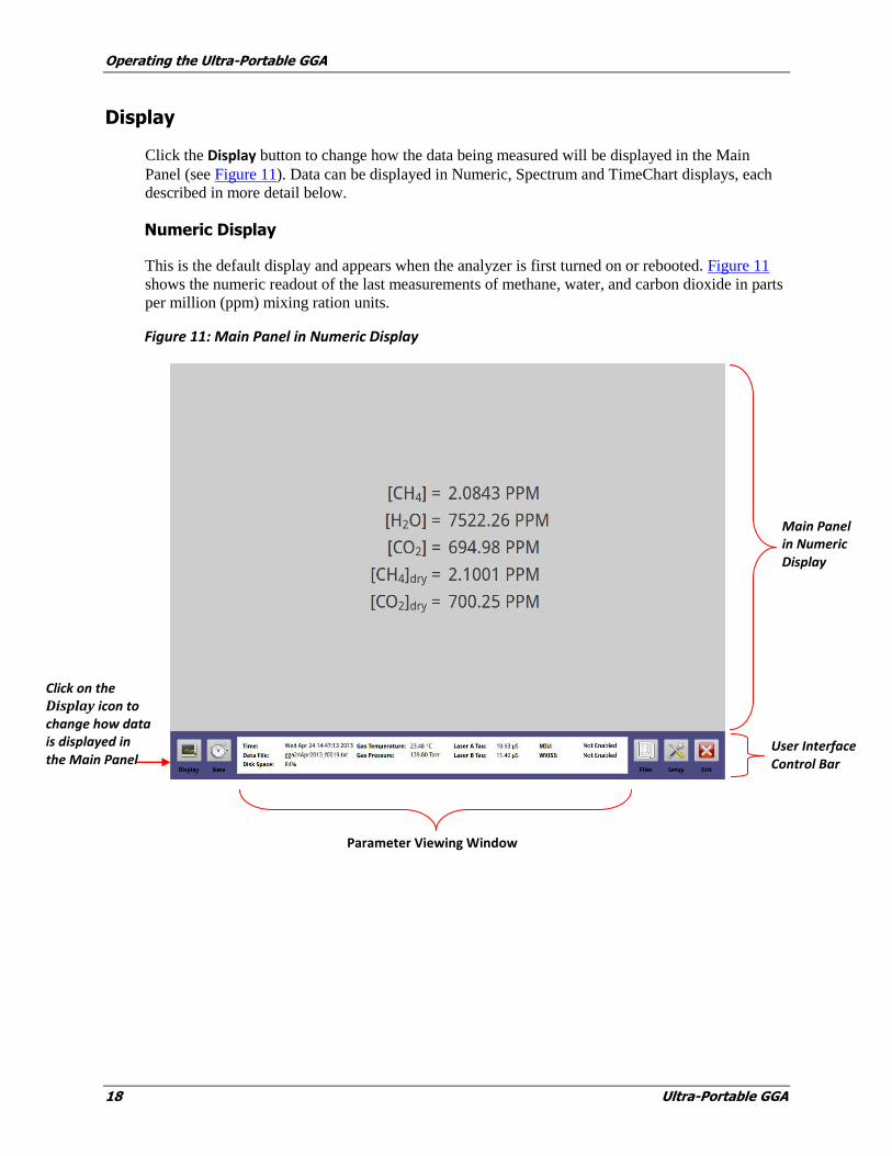
Display
Click the Display button to change how the data being measured will be displayed in the Main
Panel (see Figure 11). Data can be displayed in Numeric, Spectrum and TimeChart displays, each
described in more detail below.
Numeric Display
This is the default display and appears when the analyzer is first turned on or rebooted. Figure 11
shows the numeric readout of the last measurements of methane, water, and carbon dioxide in parts
per million (ppm) mixing ration units.
Figure 11: Main Panel in Numeric Display
Main Panel in Numeric Display
User Interface Control Bar
Parameter Viewing Window
Click on the Display icon to change how data is displayed in the Main Panel
Operating the Ultra-Portable GGA
Ultra-Portable GGA 19
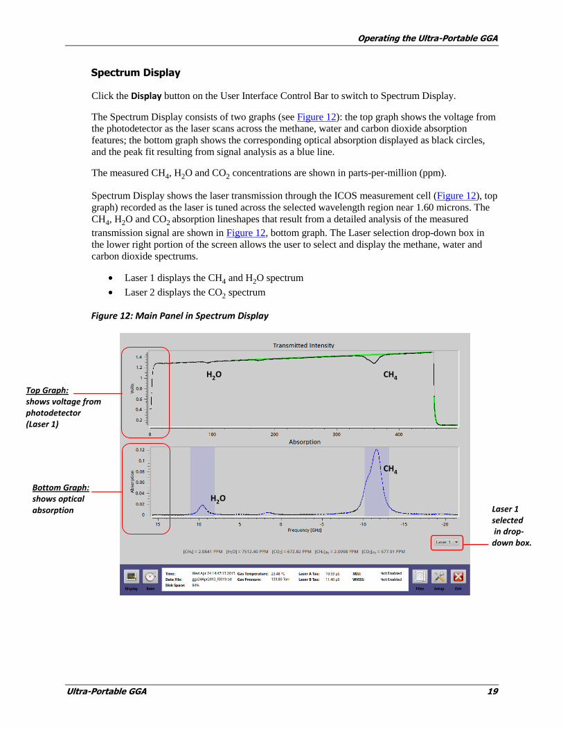
Spectrum Display
Click the Display button on the User Interface Control Bar to switch to Spectrum Display.
The Spectrum Display consists of two graphs (see Figure 12): the top graph shows the voltage from
the photodetector as the laser scans across the methane, water and carbon dioxide absorption
features; the bottom graph shows the corresponding optical absorption displayed as black circles,
and the peak fit resulting from signal analysis as a blue line.
The measured CH4, H2O and CO2 concentrations are shown in parts-per-million (ppm).
Spectrum Display shows the laser transmission through the ICOS measurement cell (Figure 12), top
graph) recorded as the laser is tuned across the selected wavelength region near 1.60 microns. The
CH4, H2O and CO2 absorption lineshapes that result from a detailed analysis of the measured
transmission signal are shown in Figure 12, bottom graph. The Laser selection drop-down box in
the lower right portion of the screen allows the user to select and display the methane, water and
carbon dioxide spectrums.
Laser 1 displays the CH4 and H2O spectrum
Laser 2 displays the CO2 spectrum
Figure 12: Main Panel in Spectrum Display
Laser 1 selected in drop-down box.
Top Graph: shows voltage from photodetector (Laser 1)
Bottom Graph: shows optical absorption
CH4
H2O
CH4 H2O

Operating the Ultra-Portable GGA
20 Ultra-Portable GGA
TimeChart Display
Click the Display button to switch to TimeChart Display.
The TimeChart shown in Figure 13 shows a continuous record of methane, water, or carbon dioxide
concentrations. A 10-point running average (in black) is shown going through the raw data (shown
in color).
Click on the drop-down box in the lower-right corner of either window to change displays of
methane, water or carbon dioxide concentrations. These data are also being saved to the file
indicated in the middle left corner of the Parameter Window, along with a continuous record of the
pressure, temperature, and mirror ring-down time.
The user may change the rate at which data are written to the log file by selecting the Rate button
(Figure 13). Data will be acquired at a 1 Hz rate and averaged for a selected interval (1 to 100
seconds) before being written to the data file and plotted on the time chart.
Longer averaging periods (or equivalently, slower data acquisition rates) will yield better
measurement precision than shorter averaging periods; so the user may trade off precision in
concentration for precision in time.
Figure 13: Main Panel in TimeChart Display
File name in which TimeChart data is being saved
Numerical drop-down box shows number of significant figures on TimeChart.
Rate button
CH4
H2O
Click on these drop-down boxes to change the displays of methane, water or carbon dioxide.

Operating the Ultra-Portable GGA
Ultra-Portable GGA 21
Rate Control
Data is collected and saved to the file indicated in the middle left of the parameter window. You
can change the rate at which data is written to the log file by selecting Rate button (clock icon) on
the User Interface Control Bar (Figure 14), and changing the speed on the Data Rate Control
Adjustment Panel. In Normal mode, data will be acquired at 1 Hz rate and averaged for a selected
interval (1 to 100 seconds) before being written to the data file and plotted on the time-chart.
Longer averaging period (or equivalently, slower data acquisition rates) will yield better
measurement precision than shorter averaging periods.
Figure 14: Data Rate Control Adjustment Screen
Rate button allows control of the rate at which data is written to the log file.
Data Rate Control Adjustment Panel
Operating the Ultra-Portable GGA
22 Ultra-Portable GGA
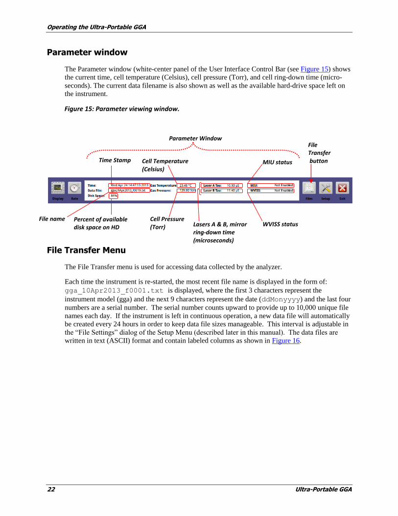
Parameter window
The Parameter window (white-center panel of the User Interface Control Bar (see Figure 15) shows
the current time, cell temperature (Celsius), cell pressure (Torr), and cell ring-down time (micro-
seconds). The current data filename is also shown as well as the available hard-drive space left on
the instrument.
Figure 15: Parameter viewing window.
File Transfer Menu
The File Transfer menu is used for accessing data collected by the analyzer.
Each time the instrument is re-started, the most recent file name is displayed in the form of:
gga_10Apr2013_f0001.txt is displayed, where the first 3 characters represent the
instrument model (gga) and the next 9 characters represent the date (ddMonyyyy) and the last four
numbers are a serial number. The serial number counts upward to provide up to 10,000 unique file
names each day. If the instrument is left in continuous operation, a new data file will automatically
be created every 24 hours in order to keep data file sizes manageable. This interval is adjustable in
the “File Settings” dialog of the Setup Menu (described later in this manual). The data files are
written in text (ASCII) format and contain labeled columns as shown in Figure 16.
File name
Parameter Window
Time Stamp
Percent of available disk space on HD
Cell Pressure (Torr)
Cell Temperature (Celsius)
Lasers A & B, mirror ring-down time (microseconds)
MIU status
WVISS status
File Transfer button
Operating the Ultra-Portable GGA
Ultra-Portable GGA 23
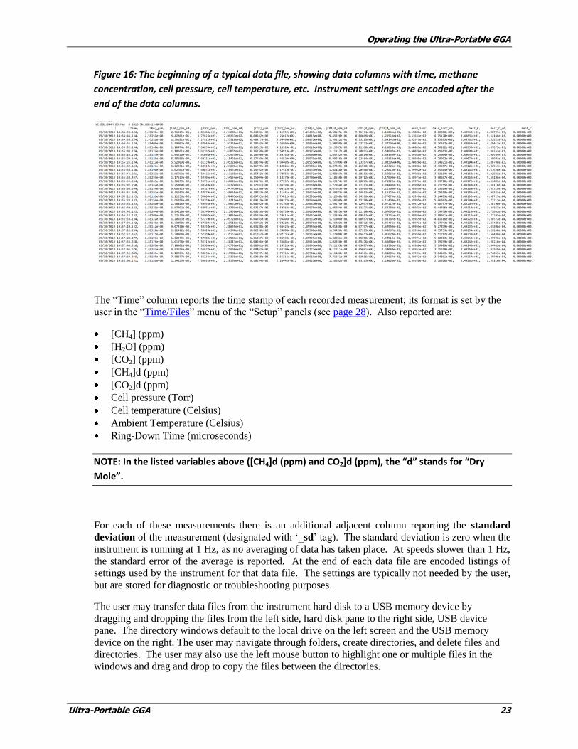
Figure 16: The beginning of a typical data file, showing data columns with time, methane
concentration, cell pressure, cell temperature, etc. Instrument settings are encoded after the
end of the data columns.
The “Time” column reports the time stamp of each recorded measurement; its format is set by the
user in the “Time/Files” menu of the “Setup” panels (see page 28). Also reported are:
[CH4] (ppm)
[H2O] (ppm)
[CO2] (ppm)
[CH4]d (ppm)
[CO2]d (ppm)
Cell pressure (Torr)
Cell temperature (Celsius)
Ambient Temperature (Celsius)
Ring-Down Time (microseconds)
NOTE: In the listed variables above ([CH4]d (ppm) and CO2]d (ppm), the “d” stands for “Dry
Mole”.
For each of these measurements there is an additional adjacent column reporting the standard
deviation of the measurement (designated with ‘_sd’ tag). The standard deviation is zero when the
instrument is running at 1 Hz, as no averaging of data has taken place. At speeds slower than 1 Hz,
the standard error of the average is reported. At the end of each data file are encoded listings of
settings used by the instrument for that data file. The settings are typically not needed by the user,
but are stored for diagnostic or troubleshooting purposes.
The user may transfer data files from the instrument hard disk to a USB memory device by
dragging and dropping the files from the left side, hard disk pane to the right side, USB device
pane. The directory windows default to the local drive on the left screen and the USB memory
device on the right. The user may navigate through folders, create directories, and delete files and
directories. The user may also use the left mouse button to highlight one or multiple files in the
windows and drag and drop to copy the files between the directories.
Operating the Ultra-Portable GGA
24 Ultra-Portable GGA
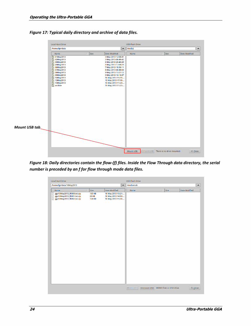
Figure 17: Typical daily directory and archive of data files.
Figure 18: Daily directories contain the flow-(f) files. Inside the Flow Through data directory, the serial
number is preceded by an f for flow through mode data files.
Mount USB tab
Operating the Ultra-Portable GGA
Ultra-Portable GGA 25
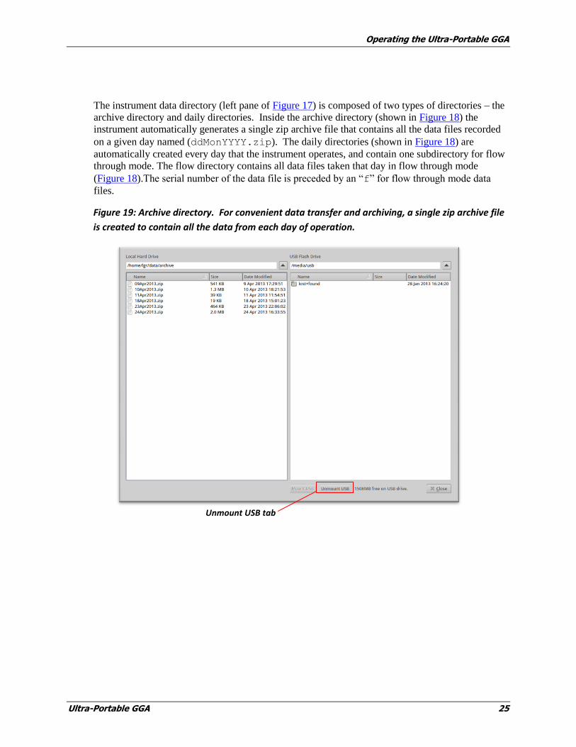
The instrument data directory (left pane of Figure 17) is composed of two types of directories – the
archive directory and daily directories. Inside the archive directory (shown in Figure 18) the
instrument automatically generates a single zip archive file that contains all the data files recorded
on a given day named (ddMonYYYY.zip). The daily directories (shown in Figure 18) are
automatically created every day that the instrument operates, and contain one subdirectory for flow
through mode. The flow directory contains all data files taken that day in flow through mode
(Figure 18).The serial number of the data file is preceded by an “f” for flow through mode data
files.
Figure 19: Archive directory. For convenient data transfer and archiving, a single zip archive file
is created to contain all the data from each day of operation.
Unmount USB tab
Operating the Ultra-Portable GGA
26 Ultra-Portable GGA
NOTE: Files may be managed within the local drive by selecting and dragging and dropping files
into designated folders. Files can then be organized into directories by creating a folder, copying
the desired files to that folder, then deleting the original files.
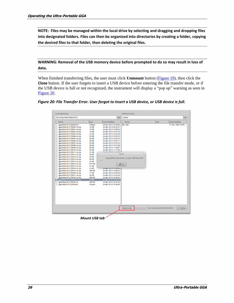
WARNING: Removal of the USB memory device before prompted to do so may result in loss of
data.
When finished transferring files, the user must click Unmount button (Figure 19), then click the
Close button. If the user forgets to insert a USB device before entering the file transfer mode, or if
the USB device is full or not recognized, the instrument will display a “pop up” warning as seen in
Figure 20.
Figure 20: File Transfer Error. User forgot to insert a USB device, or USB device is full.
Mount USB tab

Operating the Ultra-Portable GGA
Ultra-Portable GGA 27
Setup Panel
The Setup Panel allows access to additional configuration and service menus.
To enter Setup mode:
1. Click the Setup button on the User Interface Control Bar (Figure 21).
Figure 21: Setup button on the User Interface Control Bar
2. When entering Setup mode, it will display the default Time/Files screen on the Setup Menu
Panel (Figure 22).
Figure 22: Setup Menu Tabs with Time/Files screen selected
The Setup Menu Panel has specific function tabs at the top of the screen that allows the user to
configure the instrument mode and settings. These tabs allow the user to:
Manage file saving settings
Adjust the current time/date settings
Configure the Serial Output
Configure analog output
Calibrate the instrument to a local gas standard
Setup button
Setup Menu Panel tabs with Time/Files selected
Operating the Ultra-Portable GGA
28 Ultra-Portable GGA
Enable the laser offset adjustment.
Configure the optional Multi-port Inlet Unit (Manifold)
The following menus are available to make adjustments to the analyzer and its operation:
Time/File Settings Menu
The Time/File Settings Menu allows the user to adjust the timestamp format of the data files and
the new file creation interval (when running continuously). The available timestamp formats are
shown below in Table 2.
The Time/Files screen also has other adjustment menus for setting the time zone, manually setting
the clock, adjusting the Serial Configuration, and adjusting the Analog Output setting.
Table 2: Available Time Stamp Formats.
Absolute Local American mm/dd/yyy, hh.:mm:ss.sss
Absolute Local European dd/mm/yyyy, hh:mm:ss.sss
Absolute GMT American mm/dd/yyy, hh.:mm:ss.sss
Absolute GMT European dd/mm/yyyy, hh:mm:ss.sss
Relative Seconds After Power On ssssss.sss
Relative Seconds in Hours, Minutes, Seconds hh:mm:ss.sss
Clock Set Menu
The Clock Set Menu lets the user adjust the current time and date settings of the instrument
(Figure 23).The time zone and daylight savings enable/disable may also be set here.
Serial Configuration Menu
The Serial Configuration Menu (Figure 23) allows the user to change how the data reported at the
RS-232 port is configured. Standard settings for Baud Rate, Parity, and Stop Bits are provided.
Note that the actual rate of serial output is equal to the Logged File Rate (i.e. 1 Hz) divided by the
Rate specified in the Serial Configuration Menu.
NOTE: When connecting the serial port of the instrument to an external computer, a null
modem type serial cable should be used.
Operating the Ultra-Portable GGA
Ultra-Portable GGA 29
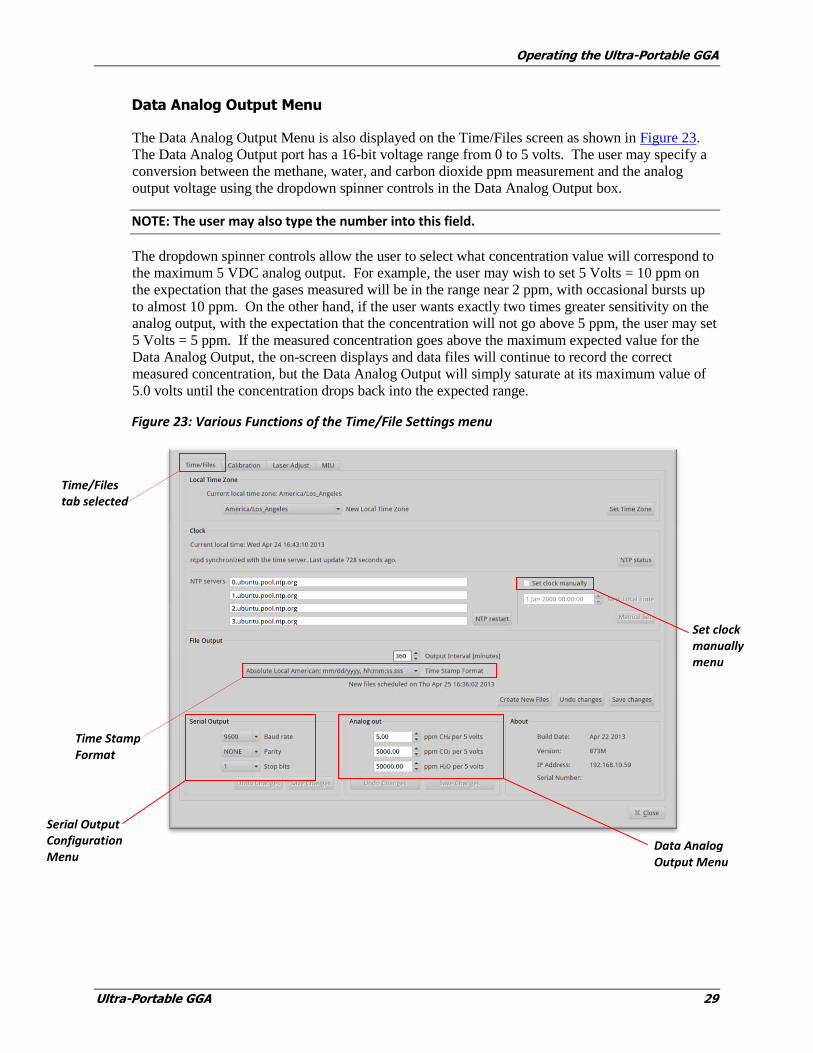
Data Analog Output Menu
The Data Analog Output Menu is also displayed on the Time/Files screen as shown in Figure 23.
The Data Analog Output port has a 16-bit voltage range from 0 to 5 volts. The user may specify a
conversion between the methane, water, and carbon dioxide ppm measurement and the analog
output voltage using the dropdown spinner controls in the Data Analog Output box.
NOTE: The user may also type the number into this field.
The dropdown spinner controls allow the user to select what concentration value will correspond to
the maximum 5 VDC analog output. For example, the user may wish to set 5 Volts = 10 ppm on
the expectation that the gases measured will be in the range near 2 ppm, with occasional bursts up
to almost 10 ppm. On the other hand, if the user wants exactly two times greater sensitivity on the
analog output, with the expectation that the concentration will not go above 5 ppm, the user may set
5 Volts = 5 ppm. If the measured concentration goes above the maximum expected value for the
Data Analog Output, the on-screen displays and data files will continue to record the correct
measured concentration, but the Data Analog Output will simply saturate at its maximum value of
5.0 volts until the concentration drops back into the expected range.
Figure 23: Various Functions of the Time/File Settings menu
Time Stamp Format
Time/Files tab selected
Serial Output Configuration Menu
Set clock manually menu
Data Analog Output Menu

Operating the Ultra-Portable GGA
30 Ultra-Portable GGA
Calibration Menu
The Ultra-Portable GGA is equipped with a calibration routine. Los Gatos Research recommends
periodic referencing rather than user calibration to ensure measurement accuracy and consistency.
However, if the user desires to calibrate the instrument, then follow these steps.
Calibration can be achieved by attaching a tube, regulated at a pressure just slightly above ambient
atmosphere (< 10 psig), from a local gas standard to the instrument inlet. The sequence of
calibration steps is illustrated below.
1. Click the Calibration tab on The Setup Menu Panel to bring up the Calibration Setup Screen
window (Figure 24), which displays information about the most recent calibration. To start
Calibration, enter data in Total ppm dropdown menu, and then click START.
Figure 24: Calibration Setup Screen
2. Toggle and select the desired reference gas setting in the Calibrate selection box (Figure 25)
and then click the NEXT button.
Calibration Tab selected
Most recent calibration
After entering calibration data, Click the START button once it becomes active.

Operating the Ultra-Portable GGA
Ultra-Portable GGA 31
Figure 25: Calibration Menu, Ready to Calibrate.
3. Click the Next button after opening the reference gas valve, (Figure 25).
4. The instrument then proceeds to the Equilibrating reference gas mode, (Figure 26).
5. Enter the known total concentration (in ppm) of the individual gas to be calibrated (CH4, H2O,
or CO2) into the corresponding field, select the box next to the species to be calibrated, and
click NEXT.
6. The screen will prompt you that the instrument is ready to calibrate, and to click the START
button once it become active, (Figure 28).
7. Click NEXT when consistent flow has been established, the transfer tube is fully flushed with
the calibration gas, and you are ready to begin calibration.
8. Close the reference gas valve and open the sample gas valve. Click the Next button when done.
(If NEXT is not clicked within 60 seconds, calibration will be aborted and normal sample
measurement will continue).The instrument will run the calibration routine for
approximately two minutes. The screen will prompt you indicating when the calibration is
finished and that the user should disconnect the calibration gas.
NOTE: The time of latest calibration is also stored in the instrument configuration files for future
reference.
Ready to calibrate, open the reference gas valve and click the NEXT tab
Calibrate selection box. H2O selected

Operating the Ultra-Portable GGA
32 Ultra-Portable GGA
NOTE: The user may instead leave the local standard gas connected for a short time to
verify a successful calibration – to do so press OK and the instrument will resume
normal measurement mode. The user can then verify that the displayed concentration
correctly corresponds to the standard gas.
9. When Calibration is finished, you are prompted to disconnect the calibration gas.
Figure 26: Calibration Menu, Equilibrating reference gas.
Operating the Ultra-Portable GGA
Ultra-Portable GGA 33
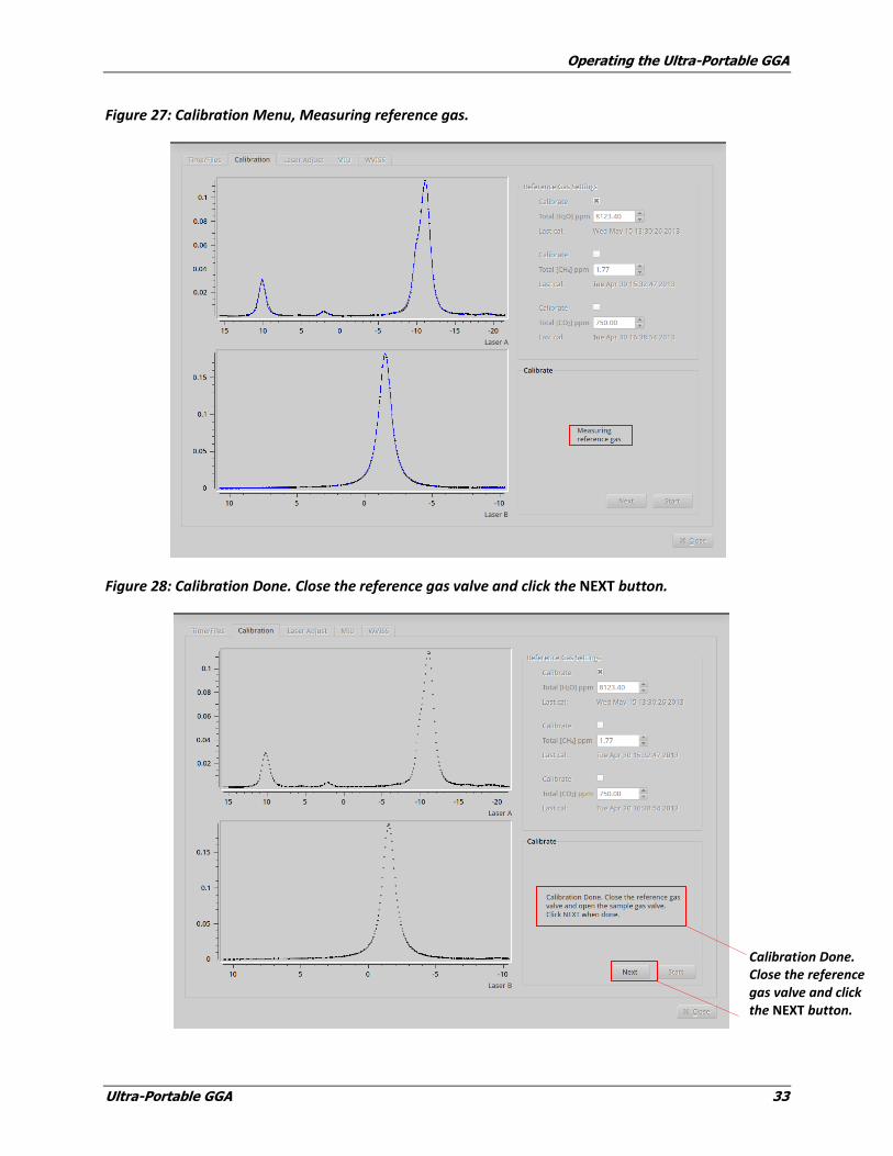
Figure 27: Calibration Menu, Measuring reference gas.
Figure 28: Calibration Done. Close the reference gas valve and click the NEXT button.
Calibration Done. Close the reference gas valve and click the NEXT button.
Operating the Ultra-Portable GGA
34 Ultra-Portable GGA
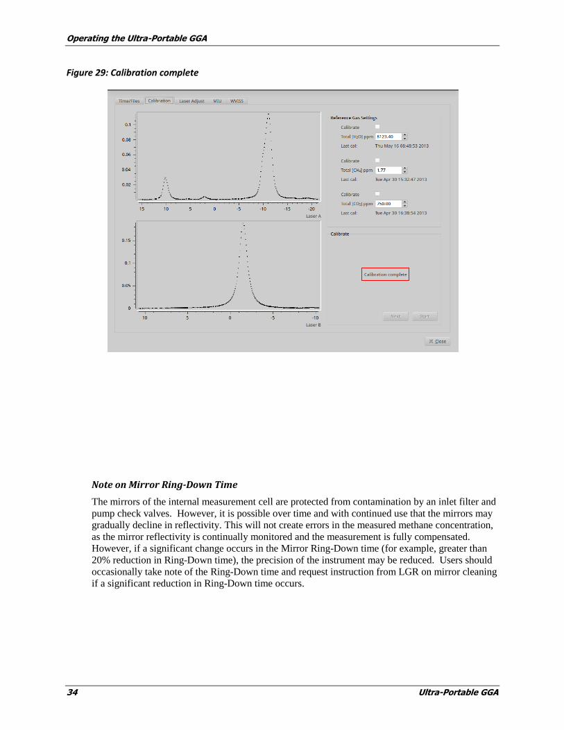
Figure 29: Calibration complete
Note on Mirror Ring-Down Time
The mirrors of the internal measurement cell are protected from contamination by an inlet filter and
pump check valves. However, it is possible over time and with continued use that the mirrors may
gradually decline in reflectivity. This will not create errors in the measured methane concentration,
as the mirror reflectivity is continually monitored and the measurement is fully compensated.
However, if a significant change occurs in the Mirror Ring-Down time (for example, greater than
20% reduction in Ring-Down time), the precision of the instrument may be reduced. Users should
occasionally take note of the Ring-Down time and request instruction from LGR on mirror cleaning
if a significant reduction in Ring-Down time occurs.
Operating the Ultra-Portable GGA
Ultra-Portable GGA 35
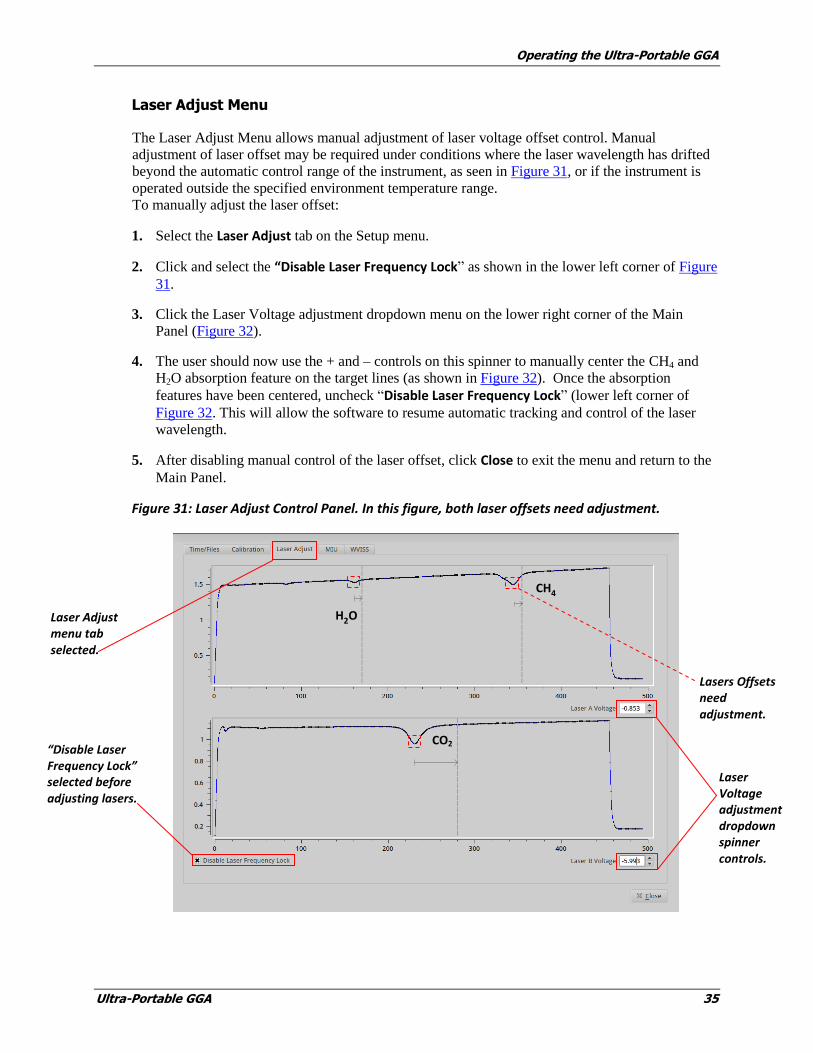
Laser Adjust Menu
The Laser Adjust Menu allows manual adjustment of laser voltage offset control. Manual
adjustment of laser offset may be required under conditions where the laser wavelength has drifted
beyond the automatic control range of the instrument, as seen in Figure 31, or if the instrument is
operated outside the specified environment temperature range.
To manually adjust the laser offset:
1. Select the Laser Adjust tab on the Setup menu.
2. Click and select the “Disable Laser Frequency Lock” as shown in the lower left corner of Figure
31.
3. Click the Laser Voltage adjustment dropdown menu on the lower right corner of the Main
Panel (Figure 32).
4. The user should now use the + and – controls on this spinner to manually center the CH4 and
H2O absorption feature on the target lines (as shown in Figure 32). Once the absorption
features have been centered, uncheck “Disable Laser Frequency Lock” (lower left corner of
Figure 32. This will allow the software to resume automatic tracking and control of the laser
wavelength.
5. After disabling manual control of the laser offset, click Close to exit the menu and return to the
Main Panel.
Figure 31: Laser Adjust Control Panel. In this figure, both laser offsets need adjustment.
Laser Adjust menu tab selected.
H2O
Lasers Offsets need adjustment.
Laser Voltage adjustment dropdown spinner controls.
CH4
CO2 “Disable Laser Frequency Lock” selected before adjusting lasers.
Operating the Ultra-Portable GGA
36 Ultra-Portable GGA
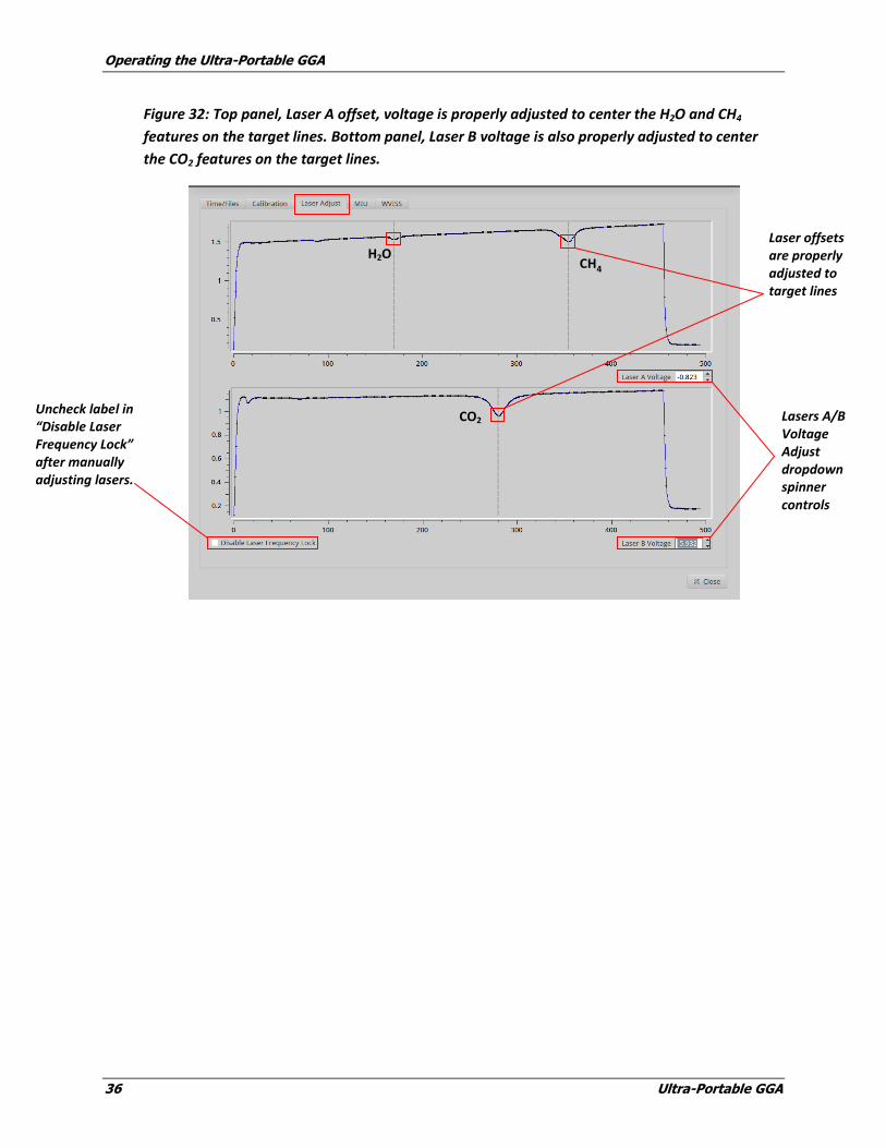
Figure 32: Top panel, Laser A offset, voltage is properly adjusted to center the H2O and CH4
features on the target lines. Bottom panel, Laser B voltage is also properly adjusted to center
the CO2 features on the target lines.
Laser offsets are properly adjusted to target lines
Lasers A/B Voltage Adjust dropdown spinner controls
CH4
CO2 Uncheck label in “Disable Laser Frequency Lock” after manually adjusting lasers.
H2O

Operating the Ultra-Portable GGA
Ultra-Portable GGA 37
Manifold Menu for Multi-port Inlet Unit (Optional)
This panel configures the control of the optional Multi-port Inlet Unit (MIU) if present. Details of
its operation are further described in the corresponding section in “Appendix C: Multi-port Inlet
Unit (Optional)” on page 71. If the MIU is not present, it should be ‘disabled’ in this menu.
Figure 33: Gas Manifold Control panel for the (optional) Multi-Port Inlet Unit (see Appendix C:
Multi-port Inlet Unit [Optional] on page Appendix C: Multi-port Inlet Unit 71 for operation)
MIU menu tab selected

Operating the Ultra-Portable GGA
38 Ultra-Portable GGA
Shutting Down the Ultra-Portable GGA
To shut down the Ultra-Portable GGA, complete the following steps:
1. Click the Exit button on the User Interface Control Bar.
Figure 34: User Interface Control Bar exit button
The Exit button prompts you to verify that you want to shut down the instrument to prevent accidental
button presses from causing interruption in data acquisition.
Figure 35: Instrument Shutdown Prompt
2. Click the OK button to halt data acquisition, close the current data file and display the shutdown
screen.
Exit button
Click OK to shutdown the analyzer

Operating the Ultra-Portable GGA
Ultra-Portable GGA 39
Figure 36: Instrument Final Shutdown Screen
3. After the “You may turn off the instrument” message displays, as shown in Figure 36, the user
can safely shut off power to the instrument by pushing the ON/OFF switch on the left side of
the instrument.
NOTE: Failure to wait for the Power Down command to display before shutting off power to the
instrument may result in file system instability.

Ultra Portable GGA 41
3 Wireless Router Setup
The Ultra-Portable GGA comes with a wireless router installed in the machine, the ZyXEL Portable
Wireless Router, and can be accessed by opening the case.
This section provides instructions for configuring the wireless router so it can connect other devices
to the analyzer.
Router Modes
There are three ways or modes in which the Wireless Router can be set up:
Wireless Router Mode – This is the default mode of the Wireless Router. Use this mode
to connect devices wirelessly to the analyzer, thereby creating your own network. The
router will issue IP addresses for the analyzer and the wireless device(s).
Access Point Mode – Use this mode to connect the analyzer to an existing network via a
LAN connection. This mode does not issue IP addresses but will allow wired and wireless
devices on an existing network to access the analyzer via a LAN connection.
Client Bridge Mode – Use this mode to connect the analyzer wirelessly to an existing
network. This mode does not issues IP addresses but will allow wired or wireless devices
on an existing network to connect wirelessly to the analyzer.
Once you have configured the router according to one of the three methods above, the analyzer will
be wirelessly accessible. For wireless control of the analyzer via a remote device, you must then
install the appropriate VNC (virtual network client) software on your remote device. Instructions to
do this are in Chapter 4, “Setting up Devices for Remote Access Using VNC Software” on page 51.

Wireless Router Setup
42 Ultra-Portable GGA
Configuration for Wireless Router Mode
To configure the wireless router for wireless router mode, slide the mode switch on the router to the
“Router” position (see Figure 37)
Figure 37: Switch on Wireless Router set to Wireless Router Mode
The diagram below shows how the wireless router connects wireless devices to the analyzer. In this
“Wireless Router Mode” the wireless router forms its own network, and issues IP addresses to the
analyzer and client devices via DHCP (Dynamic Host Configuration Protocol). This mode is
primarily intended for standalone operation of the analyzer in the field.
Figure 38: Wireless Connection Diagram in Router Mode
In order for your wireless devices to access and control the analyzer, you must first install VNC
(virtual network client) software on your wireless device, and join the wireless router network. For
instructions about how to do this, see Chapter 4, “Setting up Devices for Remote Access Using
VNC Software” on page 51.

Wireless Router Setup
Ultra-Portable GGA 43
Configuration for Access Point Mode
To configure the wireless router for Access Point mode, slide the mode switch on the router to the
AP position (see Figure 39).
Figure 39: Switch on Wireless Router set to AP Mode
The diagram below shows how the router works in AP mode to connect wired and wireless devices
to the analyzer via a LAN connection. In this “Access Point Mode,” the wireless router is connected
to an existing local area network (LAN) via a standard Ethernet jack, and the analyzer and wireless
client devices are issued IP addresses via the DHCP server on that LAN. This mode is primarily
intended for connecting wired and wireless devices to the analyzer on an existing network, such as
in a laboratory or other large facility environment.
Figure 40: Wireless Connection Diagram in AP Mode
In order for your wired and wireless devices to access and control the analyzer, you must install
VNC (virtual network client) software on the device. For instructions about how to do this see
Chapter 4, “Setting up Devices for Remote Access Using VNC Software” on page 51.

Wireless Router Setup
44 Ultra-Portable GGA
Configuration for Client Bridge Mode
To configure the wireless router for Client Bridge mode, slide the mode switch to the AP position
(see Figure 41), then follow the instructions in the section below called, “Setting up the Client
Bridge Mode Configuration.”
Figure 41: Switch on Wireless Router set to AP for Client Bridge Mode
The diagram below shows how the router works in Client Bridge mode to wirelessly connect
devices on an existing network to the analyzer. In this Client Bridge Mode, the wireless router is
connected to an existing local area network (LAN) via a wireless link, and the analyzer and
wireless devices are issued IP addresses via the DHCP server on that LAN. This mode is primarily
intended for connecting the analyzer to an existing LAN in situations where a wired connection to
the LAN is not available (e.g., on the roof of a facility, or in an outbuilding).
Figure 42: Wireless Connection Diagram in AP for Client Bridge mode
Setting up the Client Bridge Mode Configuration
1. In order to configure the router to operate in Client Bridge mode, you must first connect a
computer to the wireless router via a standard Ethernet cable (wired) connection.
2. The computer then needs to be set with a Static IP address. This means that you need to
manually set an IP address on your computer. To do this, follow the steps below for the
appropriate computer system.
Wireless Router Setup
Ultra-Portable GGA 45
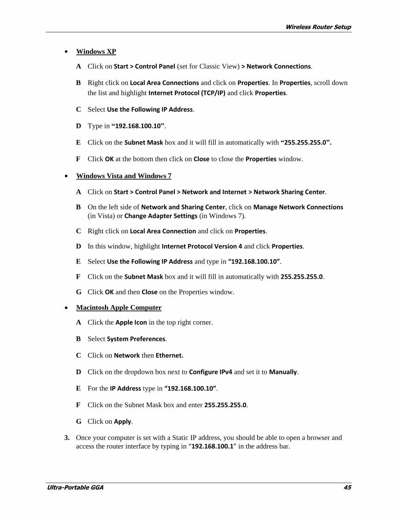
Windows XP
A Click on Start > Control Panel (set for Classic View) > Network Connections.
B Right click on Local Area Connections and click on Properties. In Properties, scroll down
the list and highlight Internet Protocol (TCP/IP) and click Properties.
C Select Use the Following IP Address.
D Type in “192.168.100.10”.
E Click on the Subnet Mask box and it will fill in automatically with “255.255.255.0”.
F Click OK at the bottom then click on Close to close the Properties window.
Windows Vista and Windows 7
A Click on Start > Control Panel > Network and Internet > Network Sharing Center.
B On the left side of Network and Sharing Center, click on Manage Network Connections
(in Vista) or Change Adapter Settings (in Windows 7).
C Right click on Local Area Connection and click on Properties.
D In this window, highlight Internet Protocol Version 4 and click Properties.
E Select Use the Following IP Address and type in “192.168.100.10”.
F Click on the Subnet Mask box and it will fill in automatically with 255.255.255.0.
G Click OK and then Close on the Properties window.
Macintosh Apple Computer
A Click the Apple Icon in the top right corner.
B Select System Preferences.
C Click on Network then Ethernet.
D Click on the dropdown box next to Configure IPv4 and set it to Manually.
E For the IP Address type in “192.168.100.10”.
F Click on the Subnet Mask box and enter 255.255.255.0.
G Click on Apply.
3. Once your computer is set with a Static IP address, you should be able to open a browser and
access the router interface by typing in “192.168.100.1” in the address bar.

Wireless Router Setup
46 Ultra-Portable GGA
Changing Your Computer Back
4. After setting up the Router, you will need to change your computer back to the way it was. Go
through the appropriate steps listed above again and
- On Windows, change the setting to Obtain an IP Address Automatically and Obtain a DNS Server Address Automatically.
- On Macintosh, change the Configure IPv4 setting to Use DHCP.
Setting up the Wireless Router
5. Flip the switch on the side of the Wireless Router from Router Mode to AP Mode
(see Figure 43).
Figure 43: Set Switch on AP
6. Open a browser window and type in “192.168.100.1” and press Enter to display the Login
Screen (see Figure 44).
Figure 44: Authentication Screen
7. The login screen for the router will display. In the User Name field, enter “admin”; in the
Password field, enter “1234”, and click Login.
Change switch to AP.

Wireless Router Setup
Ultra-Portable GGA 47
8. On the left side of the screen, click on Wireless>Basic Settings.
Figure 45: ZyXEL Wireless>Basic Settings Screen
9. Change the Wireless Mode from AP to Client, and then click Apply at the bottom of the page.
Figure: 46 Wireless Basic Settings – Changing Wireless Mode to Client
10. You will receive a message warning about using WPA/WPA2 mixed mode. This means that the
wireless router you are connecting with must be strictly in WPA or WPA2 mode, but not both.
Click on OK.
Figure 47: Warning Message
Select Basic Settings
Change to Client.
Wireless Router Setup
48 Ultra-Portable GGA
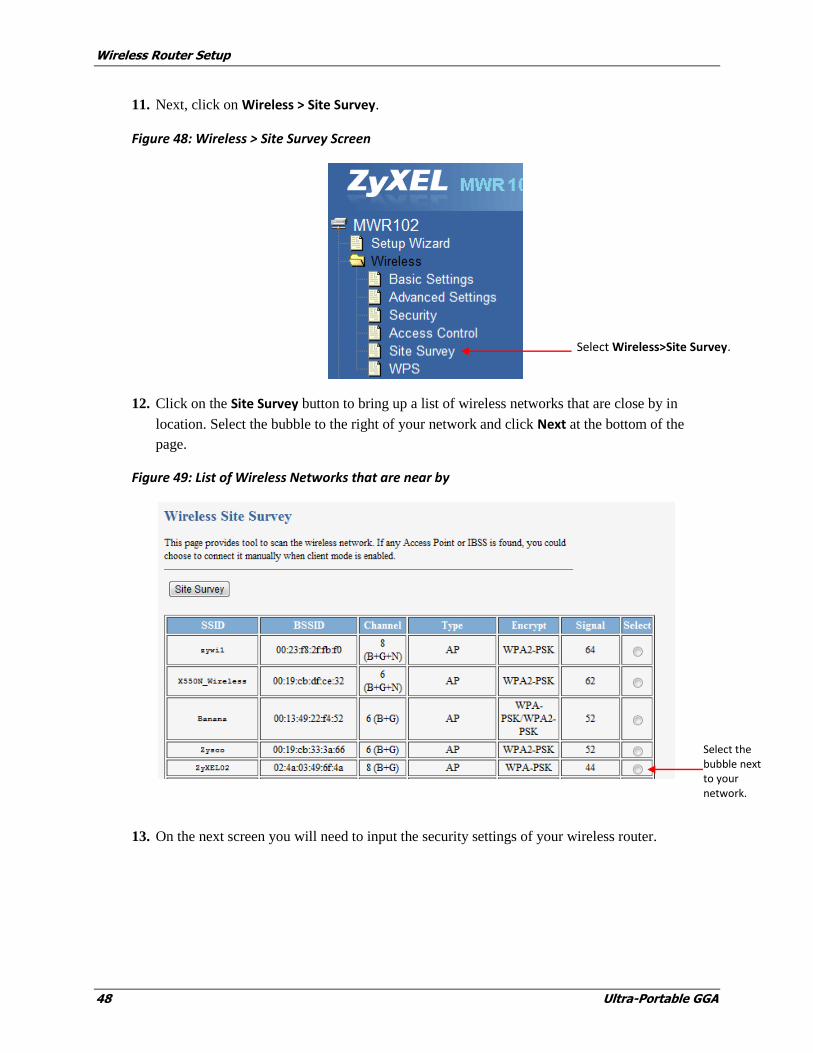
11. Next, click on Wireless > Site Survey.
Figure 48: Wireless > Site Survey Screen
12. Click on the Site Survey button to bring up a list of wireless networks that are close by in
location. Select the bubble to the right of your network and click Next at the bottom of the
page.
Figure 49: List of Wireless Networks that are near by
13. On the next screen you will need to input the security settings of your wireless router.
Select the bubble next to your network.
Select Wireless>Site Survey.
Wireless Router Setup
Ultra-Portable GGA 49
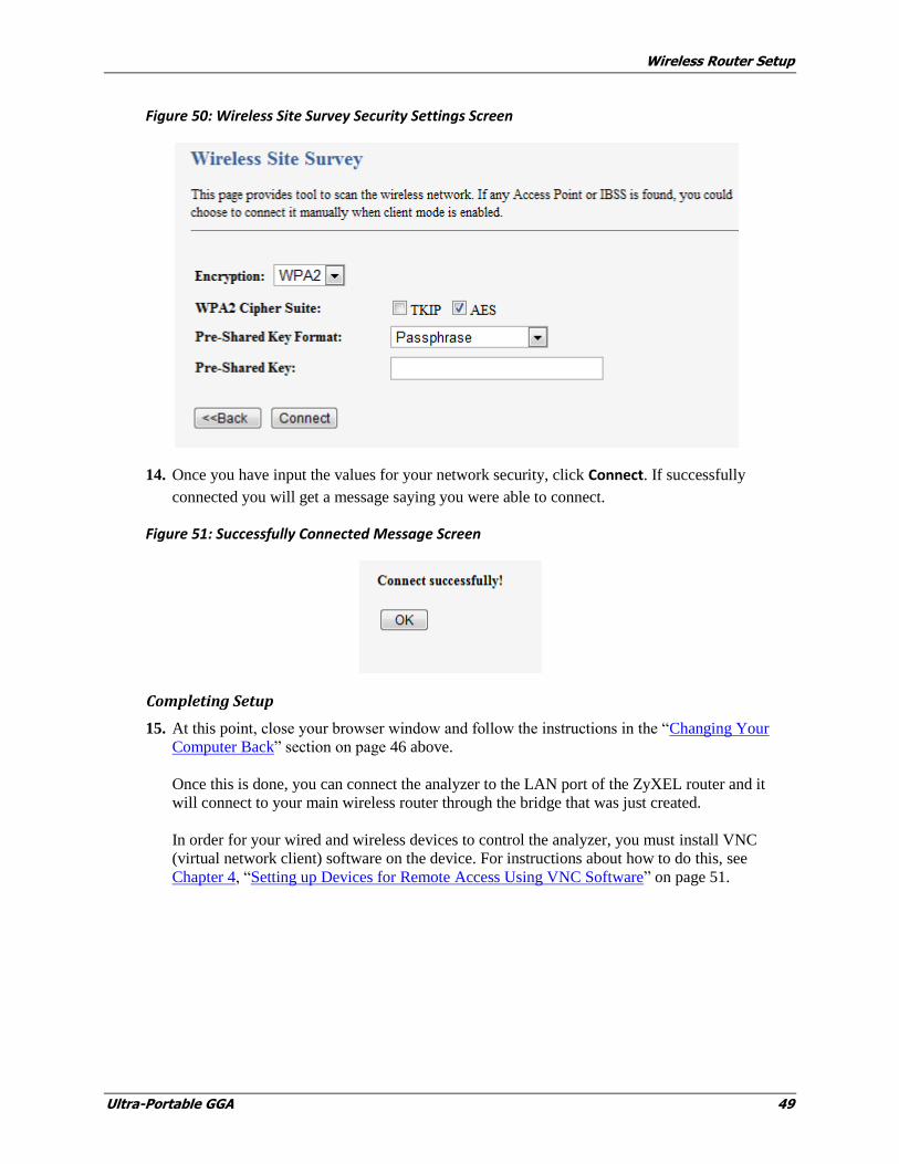
Figure 50: Wireless Site Survey Security Settings Screen
14. Once you have input the values for your network security, click Connect. If successfully
connected you will get a message saying you were able to connect.
Figure 51: Successfully Connected Message Screen
Completing Setup
15. At this point, close your browser window and follow the instructions in the “Changing Your
Computer Back” section on page 46 above.
Once this is done, you can connect the analyzer to the LAN port of the ZyXEL router and it
will connect to your main wireless router through the bridge that was just created.
In order for your wired and wireless devices to control the analyzer, you must install VNC
(virtual network client) software on the device. For instructions about how to do this, see
Chapter 4, “Setting up Devices for Remote Access Using VNC Software” on page 51.

Ultra Portable GGA 51
4 Setting up Devices for Remote Access Using VNC Software
There are three types of devices that can be connected to the analyzer through the Wireless Router
to access information:
Android OS based devices (smart phones, tablet, etc)
iOS based devices (smart phones, tablets, laptops, etc)
Windows based devices(smart phones, tablets, laptops, etc)
Each of these devices uses VNC (Virtual Network Client) software to access and control the
analyzer through the router. Follow the instructions below to install and setup VNC software on the
type of device you want to connect to the analyzer through the router.
Setting Up VNC Software on Android Devices
1. On the Android device, go to Settings>WiFi>Connect to Wireless Network.
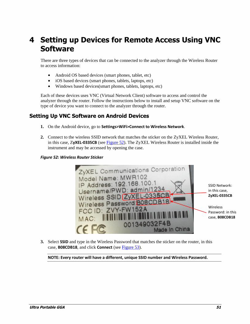
2. Connect to the wireless SSID network that matches the sticker on the ZyXEL Wireless Router,
in this case, ZyXEL-0335CB (see Figure 52). The ZyXEL Wireless Router is installed inside the
instrument and may be accessed by opening the case.
Figure 52: Wireless Router Sticker
3. Select SSID and type in the Wireless Password that matches the sticker on the router, in this
case, B08CDB18, and click Connect (see Figure 53).
NOTE: Every router will have a different, unique SSID number and Wireless Password.
Wireless Password: in this case, B08CDB18
SSID Network: in this case, ZyXEL-0335CB
Setting up Devices for Remote Access Using VNC Software
52 Ultra-Portable GGA
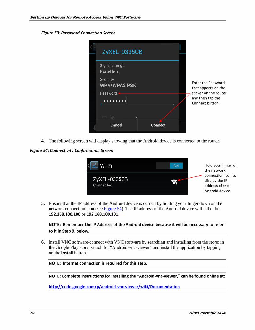
Figure 53: Password Connection Screen
4. The following screen will display showing that the Android device is connected to the router.
Figure 54: Connectivity Confirmation Screen
5. Ensure that the IP address of the Android device is correct by holding your finger down on the
network connection icon (see Figure 54). The IP address of the Android device will either be
192.168.100.100 or 192.168.100.101.
NOTE: Remember the IP Address of the Android device because it will be necessary to refer
to it in Step 9, below.
6. Install VNC software/connect with VNC software by searching and installing from the store: in
the Google Play store, search for “Android-vnc-viewer” and install the application by tapping
on the Install button.
NOTE: Internet connection is required for this step.
NOTE: Complete instructions for installing the “Android-vnc-viewer,” can be found online at:
http://code.google.com/p/android-vnc-viewer/wiki/Documentation
Hold your finger on the network connection icon to display the IP address of the Android device.
Enter the Password that appears on the sticker on the router, and then tap the Connect button.

Setting up Devices for Remote Access Using VNC Software
Ultra-Portable GGA 53
Figure 55: “Android-vnc-viewer” Install Screen
7. Open the VNC application on the Android device by tapping on the icon pictured below:
Figure 56: VNC Application Icon
Tap on the Install button to install the application.
Setting up Devices for Remote Access Using VNC Software
54 Ultra-Portable GGA
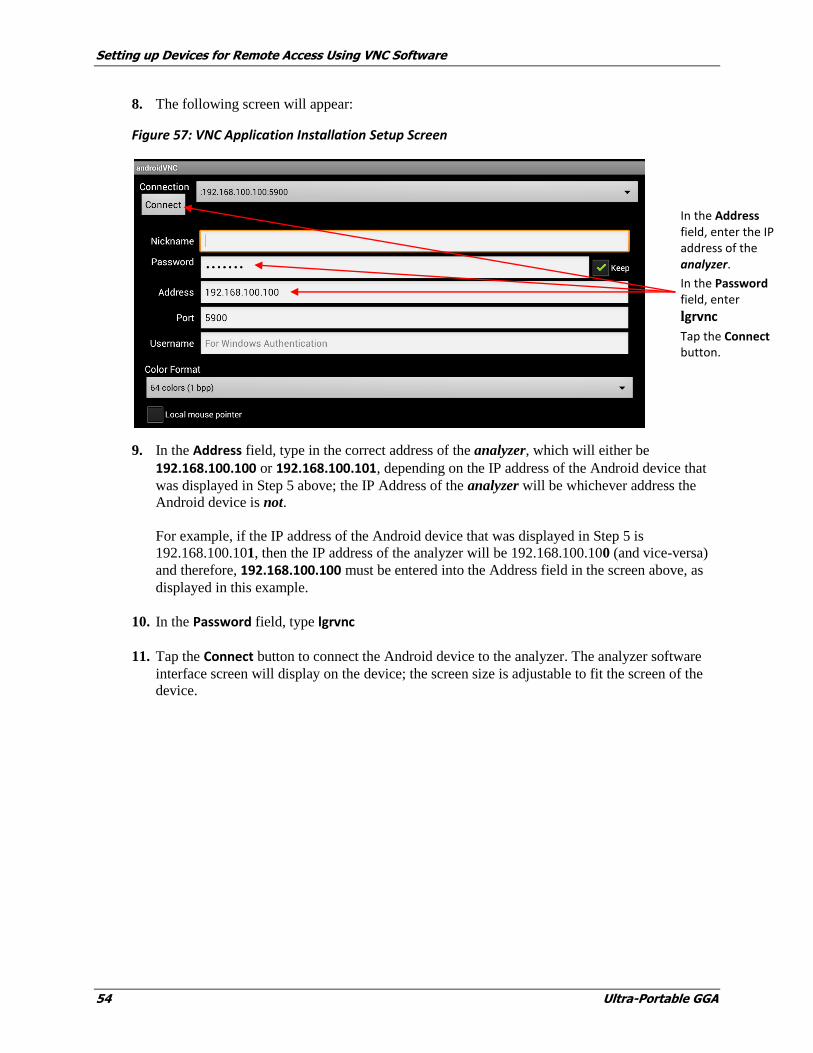
8. The following screen will appear:
Figure 57: VNC Application Installation Setup Screen
9. In the Address field, type in the correct address of the analyzer, which will either be
192.168.100.100 or 192.168.100.101, depending on the IP address of the Android device that
was displayed in Step 5 above; the IP Address of the analyzer will be whichever address the
Android device is not.
For example, if the IP address of the Android device that was displayed in Step 5 is
192.168.100.101, then the IP address of the analyzer will be 192.168.100.100 (and vice-versa)
and therefore, 192.168.100.100 must be entered into the Address field in the screen above, as
displayed in this example.
10. In the Password field, type lgrvnc
11. Tap the Connect button to connect the Android device to the analyzer. The analyzer software
interface screen will display on the device; the screen size is adjustable to fit the screen of the
device.
In the Address field, enter the IP address of the analyzer.
In the Password field, enter
lgrvnc
Tap the Connect button.

Setting up Devices for Remote Access Using VNC Software
Ultra-Portable GGA 55
Figure 58: Screen Size Adjustment Panel for Android Device
Use this slider bar to adjust screen size

Setting up Devices for Remote Access Using VNC Software
56 Ultra-Portable GGA
Setting Up VNC Software on iOS Devices
1. On the iOS device (iPad, iPhone, etc.), go to Settings>WiFi>Connect to Wireless Network.
2. Connect to the wireless SSID network that matches the sticker on the router, in this case,
ZyXEL-0335CB (see Figure 59). The ZyXEL Wireless Router is installed inside the instrument
and may be accessed by opening the case.
Figure 59: Wireless Router Sticker
3. Select the appropriate SSID network, in this case ZyXEL-0335CB (see Figure 60).
Figure 60: Network Connections Screen
Select the correct Network.
Wireless Password: in this case, B08CDB18
SSID Network: in this case, ZyXEL-0335CB

Setting up Devices for Remote Access Using VNC Software
Ultra-Portable GGA 57
4. Once selected, the following screen will appear (see Figure 61, below). In the Password field,
type in the Wireless Password on the sticker on the router, in this case, B08CDB18, and tap Join.
NOTE: Every router will have a different, unique SSID number and Wireless Password.
Figure 61: Router Connection Screen
5. The following screen will display, confirming that the iOS device is connected to the router.
Figure 62: Router Connection Confirmation Screen
Select the Network to check the IP address of the device (see Figure 63), which should be
192.168.100.100 or 192.168.100.101.
NOTE: Remember the IP Address of the device because it will be necessary to refer to it in
Step 10, below.

Setting up Devices for Remote Access Using VNC Software
58 Ultra-Portable GGA
Figure 63: Device IP Address Confirmation Screen
6. Install VNC software/connect with VNC software by searching and installing it from the App
store. Mocha VNC Lite for iOS is the software used in this example.
NOTE: Internet connection is required for this step.
NOTE: Complete instructions for installing Mocha VNC Lite for iOS can be found online at:
http://www.mochasoft.dk/iphone_vnc_help2/help.htm
Figure 64: VNC Selection Screen – Mocha VNC Lite is selected in this example
Mocha VNC Lite is the software selected.
The IP Address of the device shown here is 192.168.100.101
Setting up Devices for Remote Access Using VNC Software
Ultra-Portable GGA 59
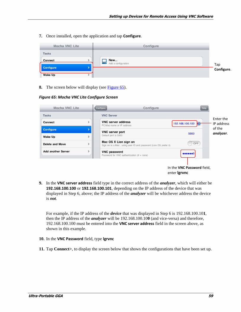
7. Once installed, open the application and tap Configure.
8. The screen below will display (see Figure 65).
Figure 65: Mocha VNC Lite Configure Screen
9. In the VNC server address field type in the correct address of the analyzer, which will either be
192.168.100.100 or 192.168.100.101, depending on the IP address of the device that was
displayed in Step 6, above; the IP address of the analyzer will be whichever address the device
is not.
For example, if the IP address of the device that was displayed in Step 6 is 192.168.100.101,
then the IP address of the analyzer will be 192.168.100.100 (and vice-versa) and therefore,
192.168.100.100 must be entered into the VNC server address field in the screen above, as
shown in this example.
10. In the VNC Password field, type lgrvnc
11. Tap Connect>, to display the screen below that shows the configurations that have been set up.
Enter the IP address of the analyzer.
In the VNC Password field,
enter lgrvnc
Tap Configure.

Setting up Devices for Remote Access Using VNC Software
60 Ultra-Portable GGA
Figure 66: Setup Configurations Screen
12. .Tap the IP Config that is setup, in this case, 192.168.100.100, to connect the iOS device to the
Analyzer. The analyzer software interface screen will display on the device; the screen size is
adjustable to fit the screen of the device (see Figure 67).
Figure 67: Screen size adjustment panel for iOS device
Tap the IP Config that is set up to connect the device to the analyzer.
Use this slider bar to adjust screen size
Setting up Devices for Remote Access Using VNC Software
Ultra-Portable GGA 61
Setting Up VNC Software on Windows Devices
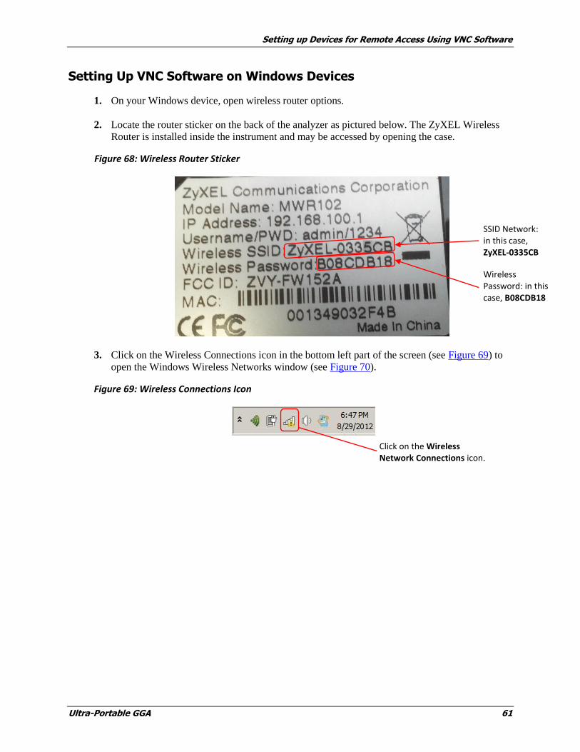
1. On your Windows device, open wireless router options.
2. Locate the router sticker on the back of the analyzer as pictured below. The ZyXEL Wireless
Router is installed inside the instrument and may be accessed by opening the case.
Figure 68: Wireless Router Sticker
3. Click on the Wireless Connections icon in the bottom left part of the screen (see Figure 69) to
open the Windows Wireless Networks window (see Figure 70).
Figure 69: Wireless Connections Icon
Click on the Wireless Network Connections icon.
Wireless Password: in this case, B08CDB18
SSID Network: in this case, ZyXEL-0335CB

Setting up Devices for Remote Access Using VNC Software
62 Ultra-Portable GGA
Figure 70: Windows Wireless Networks
4. Select the appropriate SSID network, in this case ZyXEL-0335CB (see Figure 70) to display the
screen below (Figure 71).
Figure 71: Network Connections Security Screen
5. In the Connect to a Network box that appears, in the Security key field, type in the Wireless
Password that matches the router sticker, in this case, B08CDB18, and click OK.
NOTE: Every router will have a different, unique SSID number and Wireless Password.

Setting up Devices for Remote Access Using VNC Software
Ultra-Portable GGA 63
6. Check the connection to make sure the device is connected through the Wireless Router by
selecting the router as shown in the screen below.
Figure 72: Wireless Network Connection Screen
7. Check the IP address of the Windows device by right clicking on the ZyXEL-0335CB Network
Connection, then clicking on Status (see Figure 73) to display the Wireless Network
Connection Status window (see Figure 74).
Figure 73: Current Connectivity Screen

Setting up Devices for Remote Access Using VNC Software
64 Ultra-Portable GGA
Figure 74: Wireless Network Connection Status Window
8. Click on the Details box to display the Network Connection Details window (see Figure 75).
Figure 75: Network Connection Details Window
Check the IP Address of the Windows device, which in this case, is 192.168.100.101.
Setting up Devices for Remote Access Using VNC Software
Ultra-Portable GGA 65
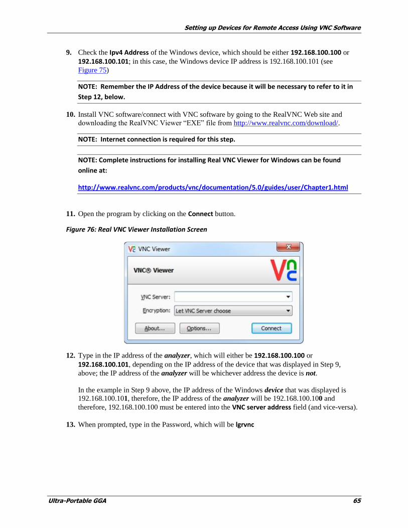
9. Check the Ipv4 Address of the Windows device, which should be either 192.168.100.100 or
192.168.100.101; in this case, the Windows device IP address is 192.168.100.101 (see
Figure 75)
NOTE: Remember the IP Address of the device because it will be necessary to refer to it in
Step 12, below.
10. Install VNC software/connect with VNC software by going to the RealVNC Web site and
downloading the RealVNC Viewer “EXE” file from http://www.realvnc.com/download/.
NOTE: Internet connection is required for this step.
NOTE: Complete instructions for installing Real VNC Viewer for Windows can be found
online at:
http://www.realvnc.com/products/vnc/documentation/5.0/guides/user/Chapter1.html
11. Open the program by clicking on the Connect button.
Figure 76: Real VNC Viewer Installation Screen
12. Type in the IP address of the analyzer, which will either be 192.168.100.100 or
192.168.100.101, depending on the IP address of the device that was displayed in Step 9,
above; the IP address of the analyzer will be whichever address the device is not.
In the example in Step 9 above, the IP address of the Windows device that was displayed is
192.168.100.101, therefore, the IP address of the analyzer will be 192.168.100.100 and
therefore, 192.168.100.100 must be entered into the VNC server address field (and vice-versa).
13. When prompted, type in the Password, which will be lgrvnc

Ultra Portable GGA 67
Appendix A: About Gas Analyzers and Laser
Absorption Spectroscopy
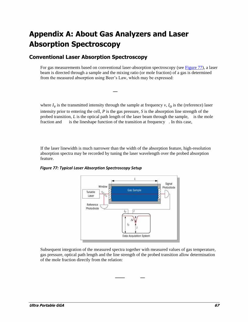
Conventional Laser Absorption Spectroscopy
For gas measurements based on conventional laser-absorption spectroscopy (see Figure 77), a laser
beam is directed through a sample and the mixing ratio (or mole fraction) of a gas is determined
from the measured absorption using Beer’s Law, which may be expressed:
where Iv is the transmitted intensity through the sample at frequency v, Io is the (reference) laser
intensity prior to entering the cell, P is the gas pressure, S is the absorption line strength of the
probed transition, L is the optical path length of the laser beam through the sample, is the mole
fraction and is the lineshape function of the transition at frequency . In this case,
If the laser linewidth is much narrower than the width of the absorption feature, high-resolution
absorption spectra may be recorded by tuning the laser wavelength over the probed absorption
feature.
Figure 77: Typical Laser Absorption Spectroscopy Setup
Subsequent integration of the measured spectra together with measured values of gas temperature,
gas pressure, optical path length and the line strength of the probed transition allow determination
of the mole fraction directly from the relation:

68 Ultra-Portable GGA
This strategy has been proven successful in determining gas concentrations in mixtures containing
several species, in flows at elevated temperatures and pressures, and in hostile environment,
without using calibration gases or reference standards.
Until recently, high-sensitivity trace-gas measurements have been possible only by using expensive
lasers (e.g., lead-salt or quantum-cascade) or broadband lamps that operate in the mid-infrared
region where absorption features are strong. LGR’s advances in cavity-enhanced absorption-
spectroscopy techniques provide dramatic increases in the optical path length (as described below)
and as a result, enable ultrasensitive trace-gas measurements using robust, reliable, room-
temperature diode lasers that operate in the near infrared.
LGR’s Off-Axis Integrated-Cavity Output Spectroscopy (Off-Axis ICOS)
Off-Axis ICOS utilizes a high-finesse optical cavity as an absorption cell as shown in Figure 78.
Unlike conventional multi-pass arrangements, which are typically limited to path lengths less than
two-hundred meters, an Off-Axis ICOS absorption cell effectively traps the laser photon so that, on
average, they make thousands of passes before leaving the cell. As a result, the effective optical
path length may be several thousands of meters using high-reflectivity mirrors and thus the
measured absorption of light after it passes through the optical cavity is significantly enhanced. For
example, for a cell composed of two 99.99% reflectivity mirrors spaced by 25 cm, the effective
optical path length is 2500 meters.
Figure 78: Schematic Diagram of an Off-Axis ICOS Instrument
Because the path length depends only on optical losses in the cavity and not on a unique beam
trajectory (like conventional multipass cells or cavity-ring-down systems), the optical alignment is
very robust allowing for reliable operation in the field. The effective optical path length is
determined routinely by simply switching the laser off and measuring the necessary time for light to
leave the cavity (typically tens of microseconds).
As with conventional tunable-laser absorption-spectroscopy methods, the wavelength of the laser is
turned over a selected absorption feature of the target species. The measured absorption spectra is
recorded and combined with measured gas temperature and pressure in the cell, effective path
length, and known line strength, used to determine a quantitative measurement of mixing ration
directly and without external calibration.

Ultra Portable GGA 69
Appendix B: Accessing Data Using a LAN Ethernet
Connection
This procedure describes how to access the analyzer data directory as a Windows™ Share via a
Local Area Network (LAN) Ethernet connection.
The data files stored on the internal hard disk drive of the analyzer may be accessed as a
Windows™ Share via a Local Area Network (LAN) ethernet connection. The following
prerequisites are necessary for this function to operate:
1. The analyzer must be connected to a Local Area Network (LAN) via the RJ-45 ethernet
connection on the rear panel.
2. The analyzer must receive a response to a DHCP (Dynamic Host Configuration Protocol)
request when the instrument is booted. If the analyzer does not receive a reply, it will disable
the ethernet port and not attempt another DHCP request until the analyzer is restarted.
When these prerequisites are met, the data directory may be accessed via a Windows computer on
the same LAN as follows:
5. Click “Start”, then “Run”, then type the following into the “Open” command field: \\LGR-XX-
XXXX (where XX-XXXX is the serial number of the analyzer).
6. In a short time (usually between 10 and 60 seconds for the first access) a Windows share
directory window will be displayed with a subdirectory named “lgrdata” displayed.
7. Double-click on the “lgrdata” directory, and you will see a listing of the data files stored on the
internal hard disk drive of the analyzer. You may open or transfer any of the data files as you
would with any Windows™ share drive.
Additional Notes
The analyzer shared data directory may (or may not) be visible by “browsing” for it in the
Windows “Network Neighborhood”. If it is, it will be in the workgroup called “LGR” and the
computer name will be “LGR-XX-XXXX” where XX-XXXX is the analyzer serial number.
You can open the data file that is currently being written into by the analyzer without
interrupting the analyzer operation (you will see a snapshot of the file as it was when you
opened it). You will notice that the current data file is only updated occasionally (every 4 kB
worth of data), so a new data file will appear empty until enough data is collected and written to
disk.
If a LAN is not available, you may plug the analyzer into a simple standalone broadband router
(such as a Netgear Model RP614 – approximately $45). This will enable the analyzer to obtain
a DHCP address from the router when the analyzer is started. You may then plug any
Windows™ computer into the same broadband router and access the data directory.
70 Ultra-Portable GGA
A “crossover” Ethernet cable will NOT allow an external computer to access the shared data
directory, as the analyzer will not obtain a DHCP address at boot and will shut down its
Ethernet interface.
You may be able to access the shared analyzer data directory from computers running operating
systems other than Windows™. The analyzer uses a Samba server to share the data directory,
and it may be accessed by any appropriate Samba client application.
Ultra Portable GGA 71
Appendix C: Multi-port Inlet Unit (Optional)
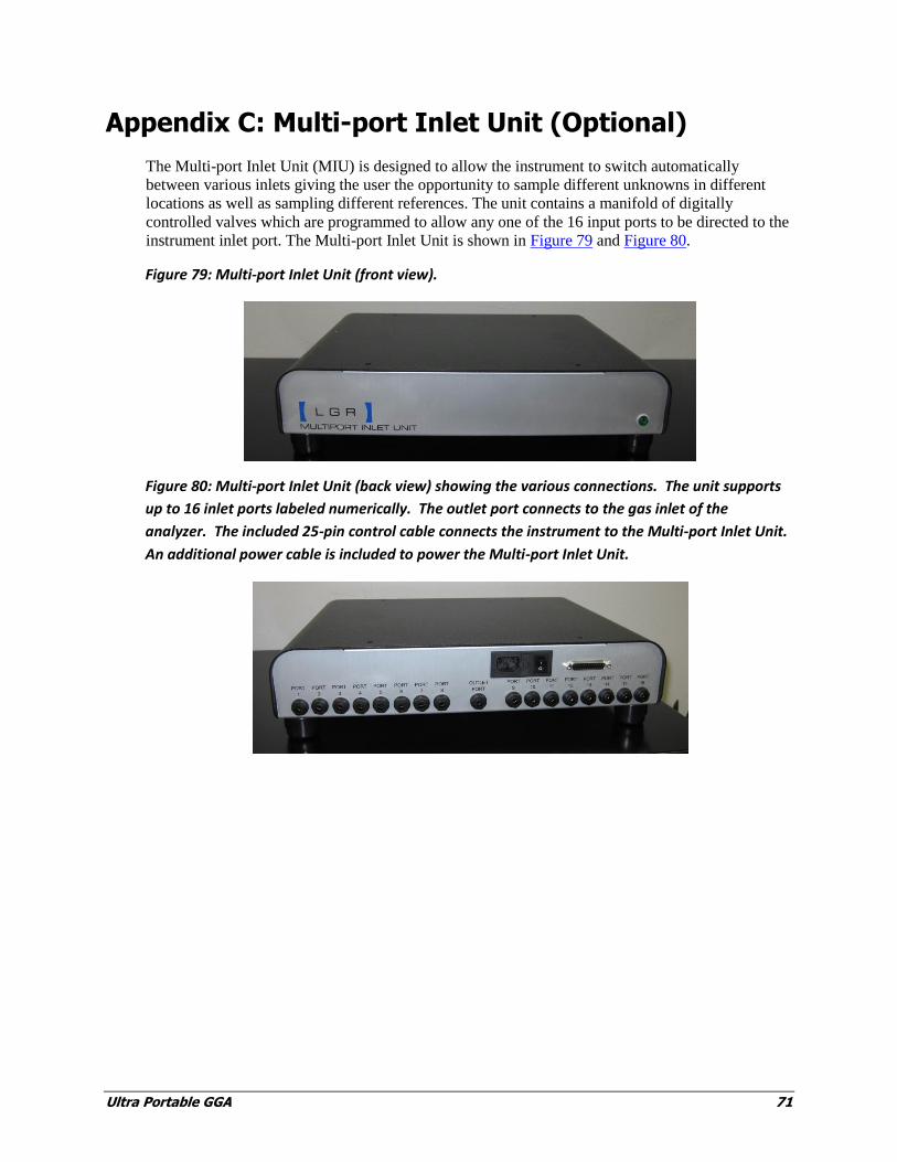
The Multi-port Inlet Unit (MIU) is designed to allow the instrument to switch automatically
between various inlets giving the user the opportunity to sample different unknowns in different
locations as well as sampling different references. The unit contains a manifold of digitally
controlled valves which are programmed to allow any one of the 16 input ports to be directed to the
instrument inlet port. The Multi-port Inlet Unit is shown in Figure 79 and Figure 80.
Figure 79: Multi-port Inlet Unit (front view).
Figure 80: Multi-port Inlet Unit (back view) showing the various connections. The unit supports
up to 16 inlet ports labeled numerically. The outlet port connects to the gas inlet of the
analyzer. The included 25-pin control cable connects the instrument to the Multi-port Inlet Unit.
An additional power cable is included to power the Multi-port Inlet Unit.
72 Ultra-Portable GGA
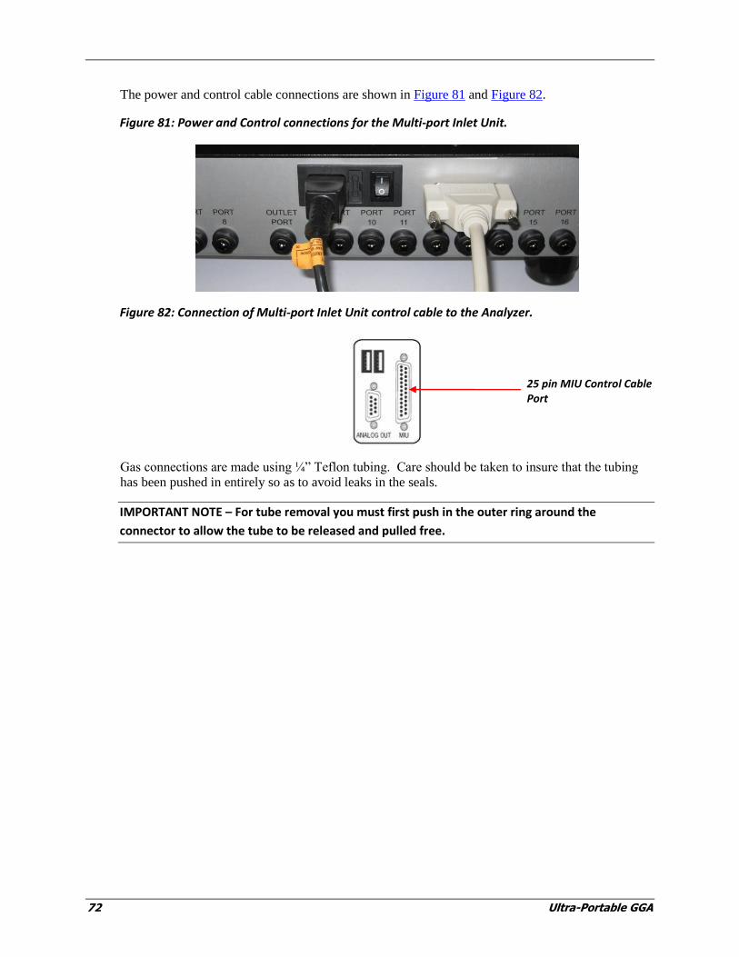
The power and control cable connections are shown in Figure 81 and Figure 82.
Figure 81: Power and Control connections for the Multi-port Inlet Unit.
Figure 82: Connection of Multi-port Inlet Unit control cable to the Analyzer.
Gas connections are made using ¼” Teflon tubing. Care should be taken to insure that the tubing
has been pushed in entirely so as to avoid leaks in the seals.
IMPORTANT NOTE – For tube removal you must first push in the outer ring around the
connector to allow the tube to be released and pulled free.
25 pin MIU Control Cable Port

Ultra-Portable GGA 73
Figure 83: The ‘Outlet Port’ of the Multi-port Inlet Unit connects to the Inlet Port of the Analyzer.
Figure 84: Insertion of sample tube into inlet port '1' on the Multi-port Inlet Unit.
IMPORTANT NOTE – for tube removal you must first push in the outer ring around the
connector to allow the tube to be released and pulled free.
The user can configure which ports are sampled and for how long. This is accessed by selecting the
Setup button on the User Interface Control Bar, and then selecting the MIU tab.

74 Ultra-Portable GGA
Figure 85: Gas manifold control for the Multi-port Inlet Unit. The user configures which inlet
ports are being used and for how long the instrument should sample each one (in seconds). The
control allows two groupings of inlets: unknown and reference. The defined inlets are sampled
sequentially with multiple unknown cycles allowed between a reference cycle. A short text
description of the inlet can also be entered which is logged in the data file along with the valve
number.
Figure 85 shows the gas manifold control for the Multi-port Inlet Unit. The user configures which
inlet ports are being used and for how long the instrument should sample each one (in seconds).
The ports are identified by a valve number ranging from 1 to 16 (if a valve is set to 0, the entry is
ignored). The user can also input a short text description which is associated with the valve, saved
in the data file, and displayed on the parameter window during the instrument run. The control
allows two groupings of inlets: ‘unknown’ and ‘reference’. All defined inlets are sampled
sequentially in their respective group. The user can decide how many cycles of the unknown group
to sample before running a reference group. The user can also indicate whether to start with the
reference group first.
The enable/disable toggle button allows the user to specify whether the unit is being used. If it is
enabled, the valve numbers and text descriptions are added to the data file to allow the user to
identify which sections of the data run are associated with a particular valve.
MIU tab selected

Ultra-Portable GGA 75
Figure 86: Selected columns from the data file showing the appended columns indicating active
valve number and user description.
While the Multi-port Inlet Unit is operating, the current valve being sampled (and its text
description) is shown on the MIU Setup Menu screen (see Figure 85). Figure 86 shows the data
files associated with the MIU’s operation. And Figure 87 (below), shows the User Interface Control
Bar with the Parameter Window indicating that the MIU is Enabled.
Figure 87: Parameter window showing the Multi-port Inlet Unit (MIU) is enabled.
The Multi-port Inlet Unit allows the user to sample multiple sources, including references, allowing
for a more automated deployment. By sampling suitable references periodically during an ongoing
data run, the user can post-correct the data for long-term drift when active calibration cannot be
done.
NOTE: The control of the Multi-port Inlet Unit is unidirectional. The instrument does not receive
feedback on the MIU state. If the MIU is enabled in the ‘Set Up’ panel, the data file will be
tagged with MIU valve descriptions whether or not the MIU is properly connected, powered,
etc; the data file simply logs the condition of the control signal to the MIU.
NOTE: The valves in the Multi-port Inlet Unit are normally closed with power off. However,
upon instrument start-up, all the valves will receive an ‘open’ signal until the instrument
software has properly booted and initiated the data collection. If pressurized tanks are
connected to the instrument (such as reference tanks), there will be a short period of time (~ 1
to 2 minutes) where the tanks will be exposed to other inlet ports during this start-up time.


Ultra Portable GGA 77
Appendix D: Warranty
Warranty Details
Each Los Gatos Research Inc. (LGR) instrument is warranted by LGR to be free from defects in
material and workmanship; however, LGR’s sole obligation under this warranty shall be to repair
or replace any part of the instrument which LGR’s examination discloses to have been defective in
material or workmanship without charge and only under the following conditions, which are:
1. The defects are called to the attention of LGR in writing within one year after the shipping date
of the instrument.
2. The instrument has not been maintained, repaired or altered by anyone was not approved by
LGR.
3. The instrument was used in the normal, proper, and ordinary manner and has not been abused,
altered, misused, neglected, involved in an accident or damaged by an act of God or other
casualty.
4. The purchaser, whether it is a distributor or direct customer of LGR or a distributor’s customer,
packs and ships or delivers the instrument to LGR (at LGR’s main office in Mountain View,
CA) within 30 days after LGR has received written notice of the defect. Unless other
arrangements have been made in writing, transportation to LGR is at customer expense.
5. No-charge repair parts may be sent at LGR’s sole discretion to the purchaser for installation by
purchaser.
6. LGR’s liability is limited to repair or replace any part of the instrument without charge if
LGR’s examination discloses that part to have been defective in material or workmanship.
The laws of some locations may not allow the exclusion or limitation on implied warranties or on
incidental or consequential damages, so the limitations herin may not apply directly. This warranty
gives you specific legal rights , and you may already have other rights which vary from location to
location. All warranties that apply, whether included by this contract or by law, are limited to the
time period of this warranty, which is a twelve-month period commencing from the date the
instrument shipped to a user who is a customer or eighteen months from the date of shipment to an
LGR-authorized distributor, whichever is earlier.
Further information concerning this warranty may be obtained by writing or telephoning the
Warranty Manager at LGR Customer Service.
LGR provides direct assistance in the use and application of all of its instruments through email,
telephone, and if necessary, in person. Training and installation services are available anywhere in
the world.
Please contact us for more details.
78 Ultra-Portable GGA
Warranty Returns
If your product is defective, you may return it during its designated warranty period for a prompt
exchange or repair. To return a product, please contact one of our sales representatives at
[email protected] to request a Return Material Authorization (RMA) number. Requests for refunds
and exchanges cannot be processed without a valid RMA number.
Please have the following information available when requesting an RMA number:
Part Number
Serial Number (if applicable)
Description of the Problem
The company-issued RMA number must be prominently displayed on the return package.
No returns will be accepted “collect” or “C.O.D.” On all warranty returns, LGR will pay the
shipping charges on the return of the merchandise to the customer.
Contact Information
For questions regarding the operation of this instrument, please contact:
Los Gatos Research
67 East Evelyn Avenue, Suite 3
Mountain View, CA 94041
Phone: 650-965-7772
Fax: 650-965-7074
Sales: [email protected]
Technical Support: [email protected]

Ultra-Portable GGA 79
Accessories and Optional Items
For prices and availability, please contact please contact LGR (650-965-7772 or
Figure 88: Ultra-Portable GGA opened and (optional) Battery/DC Power Pack with Charger and
Power Cable inside Portable Case.

80 Ultra-Portable GGA
Figure 89: AC-DC power supply (included). Figure 90: External push-connect In-line filter (included).
Figure 91: Wireless User Interface with Apple iPad (optional).
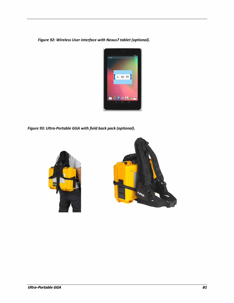
Ultra-Portable GGA 81
Figure 92: Wireless User interface with Nexus7 tablet (optional).
Figure 93: Ultra-Portable GGA with field back pack (optional).
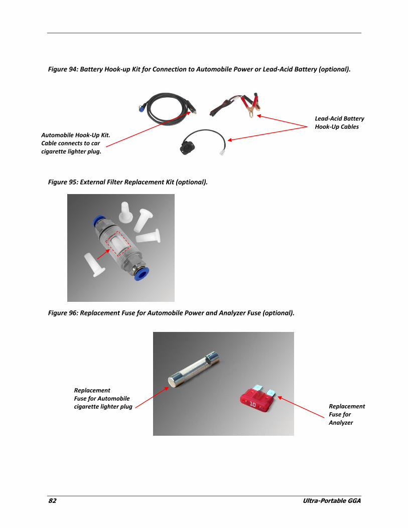
82 Ultra-Portable GGA
Figure 94: Battery Hook-up Kit for Connection to Automobile Power or Lead-Acid Battery (optional).
Figure 95: External Filter Replacement Kit (optional).
Figure 96: Replacement Fuse for Automobile Power and Analyzer Fuse (optional).
Replacement Fuse for Automobile cigarette lighter plug Replacement
Fuse for Analyzer
Automobile Hook-Up Kit. Cable connects to car cigarette lighter plug.
Lead-Acid Battery Hook-Up Cables
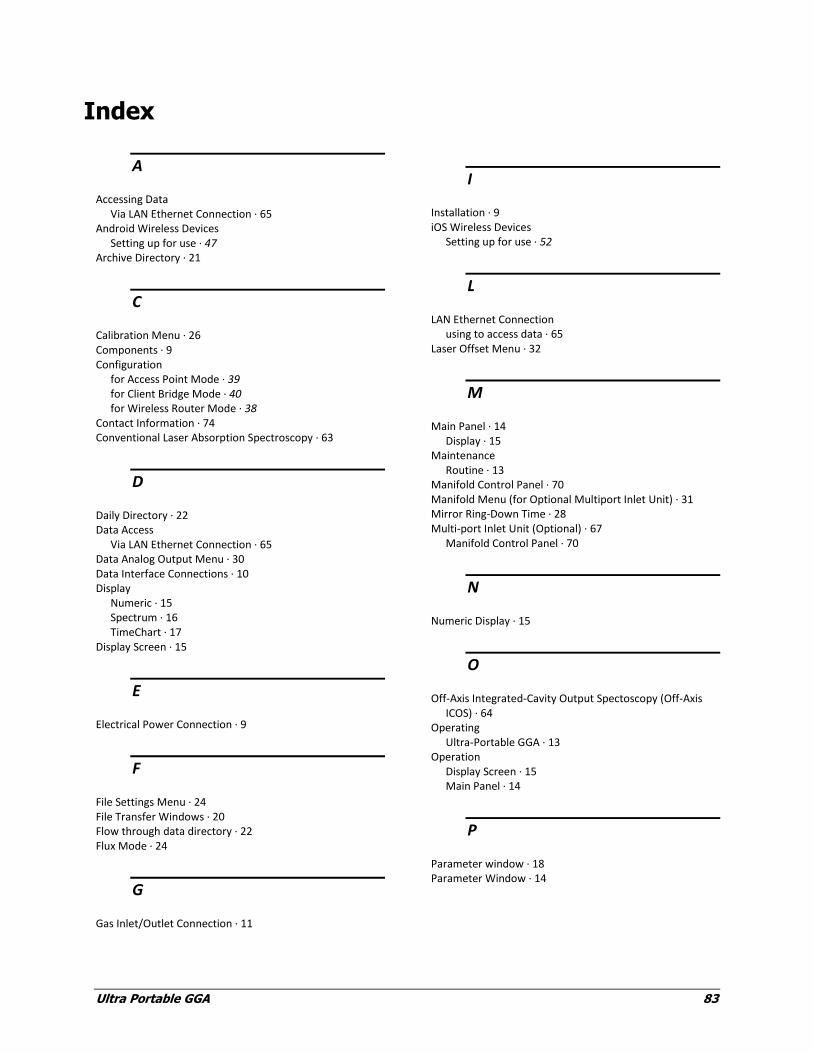
Ultra Portable GGA 83
Index
A
Accessing Data Via LAN Ethernet Connection · 65
Android Wireless Devices Setting up for use · 47
Archive Directory · 21
C
Calibration Menu · 26 Components · 9 Configuration
for Access Point Mode · 39 for Client Bridge Mode · 40 for Wireless Router Mode · 38
Contact Information · 74 Conventional Laser Absorption Spectroscopy · 63
D
Daily Directory · 22 Data Access
Via LAN Ethernet Connection · 65 Data Analog Output Menu · 30 Data Interface Connections · 10 Display
Numeric · 15 Spectrum · 16 TimeChart · 17
Display Screen · 15
E
Electrical Power Connection · 9
F
File Settings Menu · 24 File Transfer Windows · 20 Flow through data directory · 22 Flux Mode · 24
G
Gas Inlet/Outlet Connection · 11
I
Installation · 9 iOS Wireless Devices
Setting up for use · 52
L
LAN Ethernet Connection using to access data · 65
Laser Offset Menu · 32
M
Main Panel · 14 Display · 15
Maintenance Routine · 13
Manifold Control Panel · 70 Manifold Menu (for Optional Multiport Inlet Unit) · 31 Mirror Ring-Down Time · 28 Multi-port Inlet Unit (Optional) · 67
Manifold Control Panel · 70
N
Numeric Display · 15
O
Off-Axis Integrated-Cavity Output Spectoscopy (Off-Axis ICOS) · 64
Operating Ultra-Portable GGA · 13
Operation Display Screen · 15 Main Panel · 14
P
Parameter window · 18 Parameter Window · 14
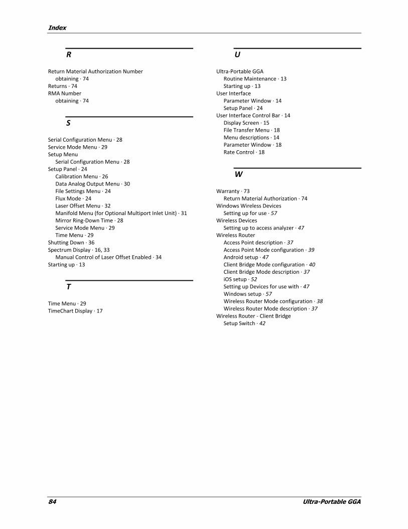
Index
84 Ultra-Portable GGA
R
Return Material Authorization Number obtaining · 74
Returns · 74 RMA Number
obtaining · 74
S
Serial Configuration Menu · 28 Service Mode Menu · 29 Setup Menu
Serial Configuration Menu · 28 Setup Panel · 24
Calibration Menu · 26 Data Analog Output Menu · 30 File Settings Menu · 24 Flux Mode · 24 Laser Offset Menu · 32 Manifold Menu (for Optional Multiport Inlet Unit) · 31 Mirror Ring-Down Time · 28 Service Mode Menu · 29 Time Menu · 29
Shutting Down · 36 Spectrum Display · 16, 33
Manual Control of Laser Offset Enabled · 34 Starting up · 13
T
Time Menu · 29 TimeChart Display · 17
U
Ultra-Portable GGA Routine Maintenance · 13 Starting up · 13
User Interface Parameter Window · 14 Setup Panel · 24
User Interface Control Bar · 14 Display Screen · 15 File Transfer Menu · 18 Menu descriptions · 14 Parameter Window · 18 Rate Control · 18
W
Warranty · 73 Return Material Authorization · 74
Windows Wireless Devices Setting up for use · 57
Wireless Devices Setting up to access analyzer · 47
Wireless Router Access Point description · 37 Access Point Mode configuration · 39 Android setup · 47 Client Bridge Mode configuration · 40 Client Bridge Mode description · 37 iOS setup · 52 Setting up Devices for use with · 47 Windows setup · 57 Wireless Router Mode configuration · 38 Wireless Router Mode description · 37
Wireless Router - Client Bridge Setup Switch · 42