ULTRA LOW EMISSION TECHNOLOGY INNOVATIONS...
13
1 Copyright © 2016 by ASME Proceedings of ASME Turbo Expo 2016: Turbine Technical Conference and Exposition GT2016 June 13-16, 2016, Seoul, South Korea GT2016-56123 ULTRA LOW EMISSION TECHNOLOGY INNOVATIONS FOR MID-CENTURY AIRCRAFT TURBINE ENGINES Tomas Grönstedt Chalmers University of Technology Göteborg, Sweden Carlos Xisto Chalmers University of Technology Göteborg, Sweden Vishal Sethi Cranfield University Cranfield, United Kingdom Andrew Rolt Cranfield University Cranfield, United Kingdom Nicolás García Rosa Institut Supérieur de l’Aéronautique et de l’Espace Toulouse, France Arne Seitz Bauhaus Luftfahrt, e.V. Ottobrunn, Germany Kyros Yakinthos Aristotle University of Thessaloniki Thessaloniki, Greece Stefan Donnerhack MTU Aero Engines AG Munich, Germany Paul Newton Rolls-Royce plc Derby, United Kingdom Nicholas Tantot SNECMA Moissy-Cramayel, France Oliver Schmitz ARTTIC Munich, Germany Anders Lundbladh GKN Aerospace Trollhättan Sweden, Sweden ABSTRACT Commercial transport fuel efficiency has improved dramatically since the early 1950s. In the coming decades the ubiquitous turbofan powered tube and wing aircraft configuration will be challenged by diminishing returns on investment with regards to fuel efficiency. From the engine perspective two routes to radically improved fuel efficiency are being explored; ultra-efficient low pressure systems and ultra- efficient core concepts. The first route is characterized by the development of geared and open rotor engine architectures but also configurations where potential synergies between engine and aircraft installations are exploited. For the second route, disruptive technologies such as intercooling, intercooling and recuperation, constant volume combustion as well as novel high temperature materials for ultra-high pressure ratio engines are being considered. This paper describes a recently launched European research effort to explore and develop synergistic combinations of radical technologies to TRL 2. The combinations are integrated into optimized engine concepts promising to deliver ultra-low emission engines. The paper discusses a structured technique to combine disruptive technologies and proposes a simple means to quantitatively screen engine concepts at an early stage of analysis. An evaluation platform for multidisciplinary optimization and scenario evaluation of radical engine concepts is outlined. INTRODUCTION Since 1971 revenue passenger kilometers (RPK) have grown by 6.5% per annum [2, 3]. In the same time frame CO2 emissions from aviation have increased yearly by 2.25% [3, 4]. This is similar to the growth of world carbon emissions from fuel combustion and cement manufacture, for which the pace is about 2.1% [5, 6]. Aviation is thus characterized both by a remarkable pace of fuel efficiency improvement as well as an exceptional rate of growth. In Europe, ambitious goals to curb CO2 emissions from aviation are proposed. In a Strategic Research and Innovation Agenda (SRIA 2050), a 75% reduction to year 2050 relative to a year 2000 reference is outlined [7]. This revolution in CO2 emissions should be achieved while fulfilling a 90% NOx and a 65% perceived noise reduction. Reaching a 75% reduction in CO2 generation is a formidable challenge that opens for several routes of realization. The SRIA 2050 does not specify how the CO2 reduction contributions will be distributed between engine and airframe, only that a 68% total efficiency is targeted. The 2050 scenario explored here envisions an ultra-efficient engine with a revolutionary core installed on an advanced tube and wing aircraft. Recent studies using advanced tube and wing concepts have shown impressive fuel efficiency improvements with far less advanced core engines. Boeing estimated a 54% fuel burn reduction with a truss braced high aspect ratio wing concept “SUGAR High” using an advanced but relatively conventional engine [8]. MIT’s double bubble lifting body concept features an advanced high aspect ratio wing targeting close to a 71% reduction in fuel burn. This concept also used an advanced engine concept with a conventional architecture core [8, 9].
Transcript of ULTRA LOW EMISSION TECHNOLOGY INNOVATIONS...

1 Copyright © 2016 by ASME
Proceedings of ASME Turbo Expo 2016: Turbine Technical Conference and Exposition GT2016
June 13-16, 2016, Seoul, South Korea
GT2016-56123
ULTRA LOW EMISSION TECHNOLOGY INNOVATIONS FOR MID-CENTURY AIRCRAFT TURBINE ENGINES
Tomas Grönstedt Chalmers University of Technology
Göteborg, Sweden
Carlos Xisto Chalmers University of Technology
Göteborg, Sweden
Vishal Sethi Cranfield University
Cranfield, United Kingdom
Andrew Rolt Cranfield University
Cranfield, United Kingdom
Nicolás García Rosa Institut Supérieur de l’Aéronautique
et de l’Espace Toulouse, France
Arne Seitz Bauhaus Luftfahrt, e.V. Ottobrunn, Germany
Kyros Yakinthos Aristotle University of Thessaloniki
Thessaloniki, Greece
Stefan Donnerhack
MTU Aero Engines AG Munich, Germany
Paul Newton Rolls-Royce plc
Derby, United Kingdom
Nicholas Tantot SNECMA
Moissy-Cramayel, France
Oliver Schmitz ARTTIC
Munich, Germany
Anders Lundbladh GKN Aerospace
Trollhättan Sweden, Sweden
ABSTRACT Commercial transport fuel efficiency has improved
dramatically since the early 1950s. In the coming decades the
ubiquitous turbofan powered tube and wing aircraft
configuration will be challenged by diminishing returns on
investment with regards to fuel efficiency. From the engine
perspective two routes to radically improved fuel efficiency are
being explored; ultra-efficient low pressure systems and ultra-
efficient core concepts. The first route is characterized by the
development of geared and open rotor engine architectures but
also configurations where potential synergies between engine
and aircraft installations are exploited. For the second route,
disruptive technologies such as intercooling, intercooling and
recuperation, constant volume combustion as well as novel high
temperature materials for ultra-high pressure ratio engines are
being considered. This paper describes a recently launched
European research effort to explore and develop synergistic
combinations of radical technologies to TRL 2. The
combinations are integrated into optimized engine concepts
promising to deliver ultra-low emission engines. The paper
discusses a structured technique to combine disruptive
technologies and proposes a simple means to quantitatively
screen engine concepts at an early stage of analysis. An
evaluation platform for multidisciplinary optimization and
scenario evaluation of radical engine concepts is outlined.
INTRODUCTION Since 1971 revenue passenger kilometers (RPK) have
grown by 6.5% per annum [2, 3]. In the same time frame CO2
emissions from aviation have increased yearly by 2.25% [3, 4].
This is similar to the growth of world carbon emissions from fuel
combustion and cement manufacture, for which the pace is about
2.1% [5, 6]. Aviation is thus characterized both by a remarkable
pace of fuel efficiency improvement as well as an exceptional
rate of growth.
In Europe, ambitious goals to curb CO2 emissions from
aviation are proposed. In a Strategic Research and Innovation
Agenda (SRIA 2050), a 75% reduction to year 2050 relative to a
year 2000 reference is outlined [7]. This revolution in CO2
emissions should be achieved while fulfilling a 90% NOx and a
65% perceived noise reduction.
Reaching a 75% reduction in CO2 generation is a formidable
challenge that opens for several routes of realization. The
SRIA 2050 does not specify how the CO2 reduction
contributions will be distributed between engine and airframe,
only that a 68% total efficiency is targeted. The 2050 scenario
explored here envisions an ultra-efficient engine with a
revolutionary core installed on an advanced tube and wing
aircraft. Recent studies using advanced tube and wing concepts
have shown impressive fuel efficiency improvements with far
less advanced core engines. Boeing estimated a 54% fuel burn
reduction with a truss braced high aspect ratio wing concept
“SUGAR High” using an advanced but relatively conventional
engine [8]. MIT’s double bubble lifting body concept features an
advanced high aspect ratio wing targeting close to a 71%
reduction in fuel burn. This concept also used an advanced
engine concept with a conventional architecture core [8, 9].
2 Copyright © 2016 by ASME
FIGURE 1. ULTIMATE ROUTE TO REALISING THE SRIA 2050 TARGETS
The breakdown of the SRIA 2050 targets proposed for the
ULTIMATE scenario outlined herein is summarized in Figure 1.
It should also be pointed out that the developed ultra efficient
cores are applicable to almost any year 2050 aircraft and
propulsion system scenario such as blended wing body concepts,
horizontal double bubble, Prandtl joined-wing concepts, turbo-
electric and hybrid propulsion concepts.
Despite the outstanding improvements that have been
achieved since the introduction of the first gas turbine turbofans,
there are still significant sources of inefficiency in propulsion
systems that could be addressed. Long range, state of the art
turbofans typically generate propulsion thrust with an overall
efficiency of around 40%. Significant improvement in
propulsion system efficiency is therefore theoretically possible.
As will be discussed in more detail, the major losses sources
occurring in state-of-the art turbofan engines are combustor
irreversibility, core exhaust thermal losses and unused kinetic
energy in the bypass flow. On-going aero engine research is well
underway to reducing the amount of unused kinetic energy in the
bypass through the introduction of advanced geared and open
rotor concepts. To systematically explore radical solutions for
reducing combustor irreversibility and core exhaust thermal
losses an EC funded research project “Ultra Low emission
Technology Innovations for Mid-century Aircraft Turbine
Engines” (ULTIMATE) has been initiated.
The ULTIMATE project, scheduled for 2015-2018, will
develop ultra efficient powerplant concepts up to TRL 2 as a
joint undertaking between four of the largest engine
manufacturers in Europe; Rolls-Royce (UK), MTU Aero
Engines (Germany), SNECMA (France), GKN aerospace
(Sweden), the four universities Chalmers University (Sweden),
Cranfield University (UK), Aristotle University of Thessaloniki
(Greece), Institut supérieur de l’aéronautique et de l’espace
(France), the research institute Bauhaus Luftfahrt as well as the
technology management company ARTTIC.
This paper is devoted to presenting a number of radical
engine concepts combining disruptive propulsion technologies
aiming for the SRIA 2050 targets. The technologies are presented
in a framework allowing a systematic search for ultra-low
emission engines. The paper also discusses how to quantitatively
screen technologies at an early project phase and describes a
multidisciplinary optimization platform used to further
investigate the down-selected concepts.
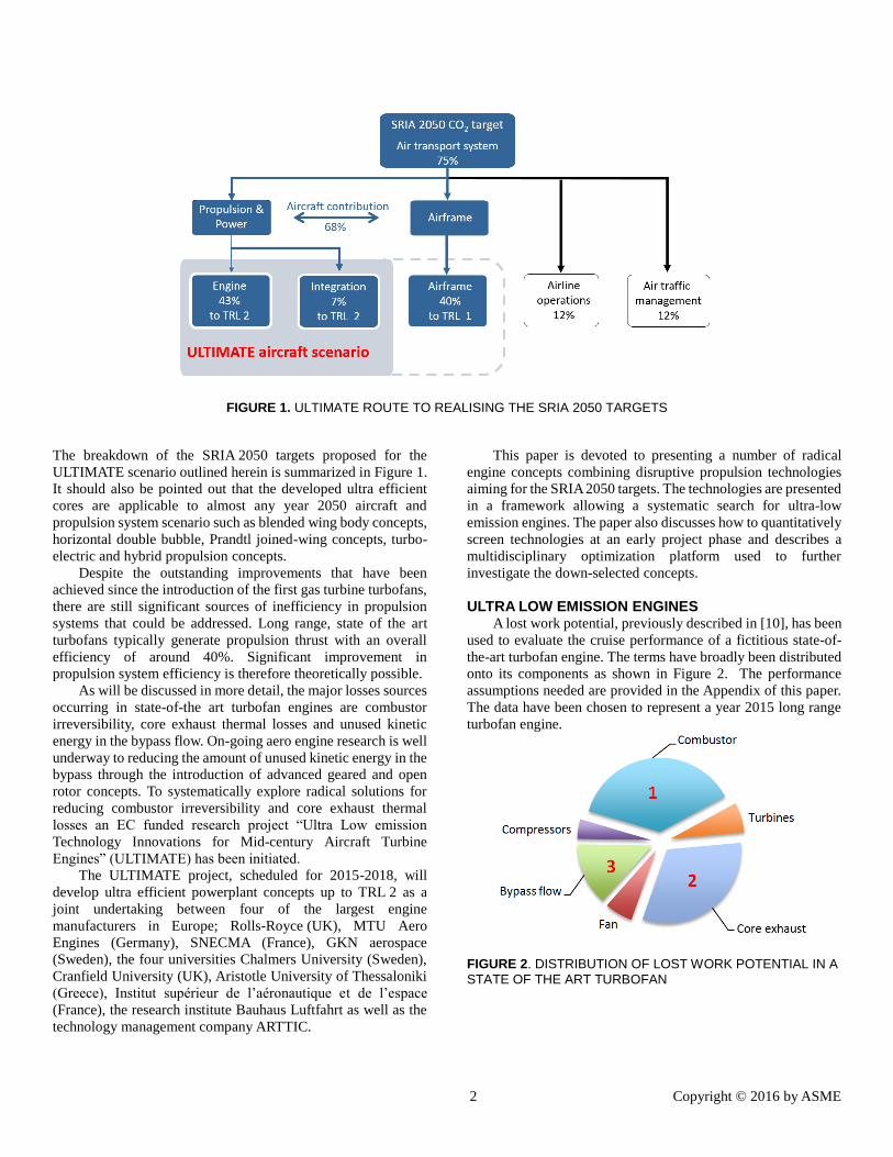
ULTRA LOW EMISSION ENGINES
A lost work potential, previously described in [10], has been
used to evaluate the cruise performance of a fictitious state-of-
the-art turbofan engine. The terms have broadly been distributed
onto its components as shown in Figure 2. The performance
assumptions needed are provided in the Appendix of this paper.
The data have been chosen to represent a year 2015 long range
turbofan engine.
FIGURE 2. DISTRIBUTION OF LOST WORK POTENTIAL IN A
STATE OF THE ART TURBOFAN
3 Copyright © 2016 by ASME
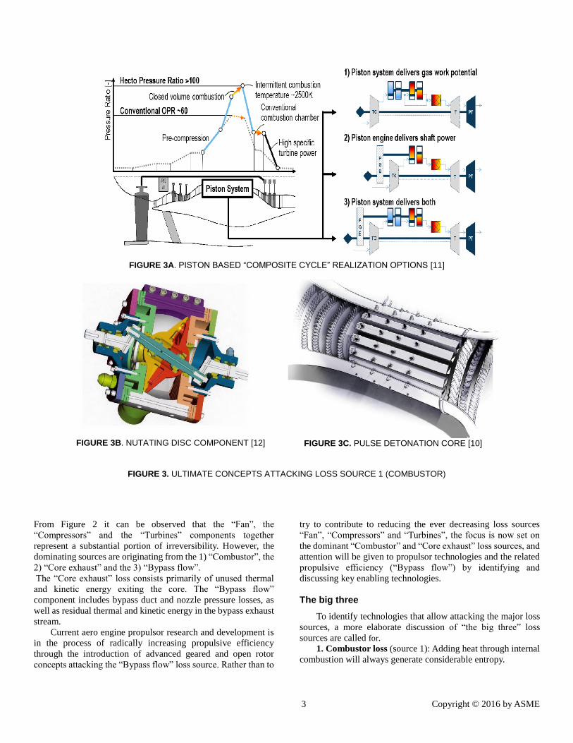
FIGURE 3A. PISTON BASED “COMPOSITE CYCLE” REALIZATION OPTIONS [11]
FIGURE 3B. NUTATING DISC COMPONENT [12]
FIGURE 3C. PULSE DETONATION CORE [10]
FIGURE 3. ULTIMATE CONCEPTS ATTACKING LOSS SOURCE 1 (COMBUSTOR)
From Figure 2 it can be observed that the “Fan”, the
“Compressors” and the “Turbines” components together
represent a substantial portion of irreversibility. However, the
dominating sources are originating from the 1) “Combustor”, the
2) “Core exhaust” and the 3) “Bypass flow”.
The “Core exhaust” loss consists primarily of unused thermal
and kinetic energy exiting the core. The “Bypass flow”
component includes bypass duct and nozzle pressure losses, as
well as residual thermal and kinetic energy in the bypass exhaust
stream.
Current aero engine propulsor research and development is
in the process of radically increasing propulsive efficiency
through the introduction of advanced geared and open rotor
concepts attacking the “Bypass flow” loss source. Rather than to
try to contribute to reducing the ever decreasing loss sources
“Fan”, “Compressors” and “Turbines”, the focus is now set on
the dominant “Combustor” and “Core exhaust” loss sources, and
attention will be given to propulsor technologies and the related
propulsive efficiency (“Bypass flow”) by identifying and
discussing key enabling technologies.
The big three
To identify technologies that allow attacking the major loss
sources, a more elaborate discussion of “the big three” loss
sources are called for.
1. Combustor loss (source 1): Adding heat through internal
combustion will always generate considerable entropy.
4 Copyright © 2016 by ASME
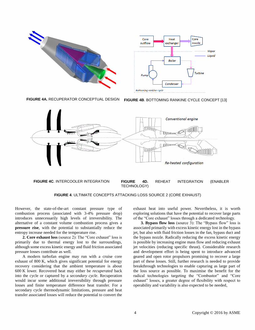
FIGURE 4A. RECUPERATOR CONCEPTUAL DESIGN
FIGURE 4B. BOTTOMING RANKINE CYCLE CONCEPT [13]
FIGURE 4C. INTERCOOLER INTEGRATION
FIGURE 4D. REHEAT INTEGRATION (ENABLER
TECHNOLOGY)
FIGURE 4. ULTIMATE CONCEPTS ATTACKING LOSS SOURCE 2 (CORE EXHAUST)
However, the state-of-the-art constant pressure type of
combustion process (associated with 3-4% pressure drop)
introduces unnecessarily high levels of irreversibility. The
alternative of a constant volume combustion process gives a
pressure rise, with the potential to substantially reduce the
entropy increase needed for the temperature rise.
2. Core exhaust loss (source 2): The “Core exhaust” loss is
primarily due to thermal energy lost to the surroundings,
although some excess kinetic energy and fluid friction associated
pressure losses contribute as well.
A modern turbofan engine may run with a cruise core
exhaust of 800 K, which gives significant potential for energy
recovery considering that the ambient temperature is about
600 K lower. Recovered heat may either be recuperated back
into the cycle or captured by a secondary cycle. Recuperation
would incur some additional irreversibility through pressure
losses and finite temperature difference heat transfer. For a
secondary cycle thermodynamic limitations, pressure and heat
transfer associated losses will reduce the potential to convert the
exhaust heat into useful power. Nevertheless, it is worth
exploring solutions that have the potential to recover large parts
of the “Core exhaust” losses through a dedicated technology.
3. Bypass flow loss (source 3): The “Bypass flow” loss is
associated primarily with excess kinetic energy lost in the bypass
jet, but also with fluid friction losses in the fan, bypass duct and
the bypass nozzle. Radically reducing the excess kinetic energy
is possible by increasing engine mass flow and reducing exhaust
jet velocities (reducing specific thrust). Considerable research
and development effort is being spent to introduce advanced
geared and open rotor propulsors promising to recover a large
part of these losses. Still, further research is needed to provide
breakthrough technologies to enable capturing as large part of
the loss source as possible. To maximise the benefit for the
radical technologies targeting the “Combustor” and “Core
exhaust” losses, a greater degree of flexibility with respect to
operability and variability is also expected to be needed,

5 Copyright © 2016 by ASME
FIGURE 5A. BOX-PROP OPEN ROTOR PROPELLER
CONCEPT [14]
FIGURE 5B. CIRCUMFERENTIALLY RETRACTABLE
NACELLE CONCEPT [15]
compared to propulsor technologies integrated on a conventional
aero engine.
ULTIMATE TECHNOLOGIES Technologies attacking the “Combustor” loss (source 1):
A breakthrough reduction in the combustor component loss can
be achieved by exploiting a constant volume type of process
rather than the constant pressure process used in a state-of-the-
art turbofan. Three technologies that might provide this benefit
are: piston engine technology (Figure 3A), nutating disc
technology (Figure 3B) and pulse detonation technology
(Figure 3C).
Piston engines, in particular Otto and Diesel types,
constitute the most successful class of non-Brayton cycle
machines, being in service in ground-based, naval and
aeronautical applications. Until the adoption of Brayton cycle
based jet engines in the 1950s, piston engines were the prevailing
aero engine type with unmatched thermal efficiency levels
comparable even with modern gas-turbine technology. Based on
the Seiliger cycle process, piston engines allow for higher peak
pressure and temperature levels and feature (partial) constant
volume combustion, thus achieving higher efficiency than
engines based on the Brayton cycle. Gas-turbine engines based
on the Brayton cycle, on the other hand, feature outstanding
power densities and low mechanical complexity compared to
traditional piston engines. Hence, combining the high pressure,
high temperature pressure gain combustion capability of the
piston technology with the specific power capability of the gas
turbine cycle to form a piston topped “composite cycle” becomes
very attractive.
The composite cycle provides new degrees of freedom for
matching and operational tailoring. Figure 3A shows concepts
delivering gas work potential (Type 1), shaft power (Type 2) and
both gas work potential and shaft power (Type 3). Even very
early composite engine realizations showed quite high
efficiencies [16]. By utilizing today’s advanced design, materials
and manufacturing methods, substantially higher performance
can be expected.
An alternative to the piston based composite technology is
provided by the nutating disc concept illustrated in Figure 3B.
The implementation is, in contrast to piston technology, a quite
recent innovation [12]. Like the piston engine, this concept
works on an intermittent combustion cycle. The key component,
the disc, is mounted at an angle to a Z-shaped shaft. As the shaft
rotates on its vertical axis, it internally twists the disk, so that the
disk performs a nutating (wobbling) motion without rotating in
the direction of the shaft. The motion is similar to the periodic
motion of a coin wobbling on a flat surface. A major advantage
of the nutating engine is that each side of the disk is used once
per engine revolution promising to provide a low weight constant
volume based combustion solution. The nutating motion is also
associated with a relatively low levels of vibration. Having been
developed and tested for a UAV engine, the concept is hoped to
provide a low vibration, high efficiency and highly compact
solution. The three variants proposed for the piston topped
composite cycle, as presented in Figure 3A, are equally of
interest with the nutating disc topped concept. In addition, both
composite engine types may benefit from intercooling and/or the
addition of a second (constant pressure) combustor, with the
potential benefits of increased specific power, increased thermal
efficiency and reduced emissions. Apart from architectural
arrangements, key technology challenges involve the aero-
thermodynamic interaction of the piston and turbo components,
and engine rating and part power optimization and maintaining
an efficient ultra-low emission combustion processes.
The proposed implementation of the pulse detonation core
concept [10] differs from the two reciprocating concepts by not
requiring the additional conventional combustor in order to reach
the high temperatures of a gas turbine. The concept also promises
to recover some of the dynamic energy generated during the
detonation waves, theoretically outperforming the two other
constant volume combustor concepts. Key technology

6 Copyright © 2016 by ASME
challenges consist of the the aero-thermodynamic interaction of
the detonation waves and turbo components, integration of
compression intercooling to reduce risk of auto-ignition and to
ensure efficient part power operation.
For all three combustor technologies the dynamic
combustion process and shorter residence times are expected to
contribute to reduced NOx production. In conjunction with the
greatly reduced fuel burn being targeted the technologies may be
designed to deliver the 90% SRIA 2050 NOx reduction target. If
not, it is expected that some cycle limitations will be needed. The
necessary cycle limitation can be achieved by limiting the
combustor entry and flame temperatures. In turn, this can be
achieved by dropping cycle pressure ratio, or by using
intercooling. A third option is to use a reheat combustor which
allows both combustors to run at substantially lower peak
temperatures.
Technologies attacking the “Core exhaust” loss (source 2): A breakthrough reduction in core exhaust component losses can
be achieved by technologies that substantially reduce the exit
temperature in comparison with a state-of-the-art turbofan.
Three technologies that could achieve this are recuperation
(Figure 4A), Rankine bottoming (Figure 4B) as well as
intercooling (Figure 4C).
Recuperation reduces the core nozzle exit temperature
through the recovery of core exhaust heat being returned to pre-
heat the air prior to combustion. A well-known radical concept
that provides synergy with the recuperator is the use of an
intercooler [17, 18]. A freer optimization exploring the use of
alternative types of heat exchangers and different installation
locations would allow further fuel burn potential to be
established for the technology. Synergies with composite piston
topping could also provide benefits. As a more radical approach,
integration with heat transfer systems using a secondary fluid
system [19], as well as integration with inter-turbine reheat may
be considered.
The Rankine bottoming cycle technology reduces the core
nozzle exit temperature by extracting heat from the core flow
(Figure 4B). The extracted heat is used to heat a fluid within a
secondary fluid system which is used to generate additional
power. Combining a Rankine bottoming cycle with a topping gas
turbine has been a successful way to reach unrivalled efficiency
in stationary power generation. The concept of using Rankine
bottoming for flight application has recently received attention
for aero engine application [13]. Key research tasks are to
develop and optimize the secondary system with respect to
design and integration aspects of the bottoming cycle
components, to assess part load performance and to explore the
use of different secondary fluids. In particular, synergies with
intercooling and composite topping technology promises to
provide fuel burn benefits.
Intercooling is an enabler to high overall pressure ratio
engines. For a fixed combustor exit temperature, this increase in
pressure ratio then leads to a reduced core nozzle exit
temperature. Hence intercooling can be seen as a concept that
indirectly captures exhaust heat. On the other hand, it may also
serve as a concept that can be optimized to decrease compressor
exhaust temperature and allow for increased energy input from a
recuperator. Further, it could serve as an enabler for very high
bypass ratio engines by decreasing power requirement during
compression. This would allow a smaller core to drive a
fan/propulsor. Intercooling also promises to integrate well with
piston-, nutating- and pulse detonation composite topping
technologies. In addition, intercooling reduces compressor exit
temperature and hence combustor entry temperature, which in
general reduces NOx emissions.
Key intercooling technology aspects are to develop designs
that make full use of the synergistic benefits with other
ULTIMATE technologies. The technology can also be used to
explore radical installation concepts such as a split flow first
stage compressor blade. Such a configuration would allow
producing the intercooler coolant flow for an open rotor pusher
configuration. It could also be integrated into an open rotor
tractor configuration as illustrated in Figure 4C, or into a
configuration with an ultra-high overall pressure ratio (> 150).
Another concept that provides interesting potential for
synergy is inter-turbine reheat (illustrated in Figure 4D).
Reheat has been successfully used by Alstom in its GT24 and
GT26 industrial gas turbine engines. Sequential combustion
facilitates a gas turbine with a significantly higher power density
than conventional cycles [20] and is expected to integrate well
with bottoming engine technologies such as recuperation and
Rankine bottoming. By allowing another degree of freedom in
terms of introducing heat into the engine the maximum
combustor temperature can be kept down which supports a
drastic reduction in NOx generation. In addition the reheat
concept will increase core specific power which allows for
weight reduction and ultra-high bypass ratios. Breakthrough
materials such as ceramic matrix composite materials (such as
SiC) should be used to minimize cooling requirements for the
second combustor and would be a key technology enabler for its
success.
Technologies attacking the “Bypass flow” loss (source 3): A large part of the reduction of this loss source, as needed to
achieve the SRIA 2050 targets, is expected from the use of
advanced powerplant architectures targeting ultra-high
propulsive efficiency. In the scenarios outlined here, this
comprises an advanced geared turbofan engine for long range
missions and an open rotor concept primarily targeting short and
medium range missions. These engine architectures are already
at high TRL levels and will only be modelled to support the
radical core concepts being explored. In addition to this
propulsion plant modelling effort, a number of advanced
technologies supporting the integration of the cores are planned
to be modelled.The technologies attacking the “Bypass flow”
loss thus serve a two-fold purpose:
1. Provide a propulsor platform on to which the core
technologies attacking the “Combustor” and “Core
exhaust” losses can be integrated and optimized.
2. Provide radical enabling technology that will allow
further reduction of the “Bypass flow” loss and have the
potential to radically reduce noise.

7 Copyright © 2016 by ASME
Integration technologies to be explored cover: ultra-thin adaptive
inlet and adaptive external shapes, circumferentially retractable
concepts as illustrated in Figure 5B. Means to provide variable
fan flow capacity and operability using variable pitch fan rotors,
variable bypass and core nozzles and variable inlet guide vanes
as well as means to provide open rotor variability including
advanced blade actuation systems and pitch control mechanisms.
In addition, a box-blade open rotor propeller concept, as
illustrated in Figure 5, allowing a forward swept first rotor and
maximum rotor separation for noise reduction will be optimized
as part of the project.
The Advanced Tube and Wing configurations The ULTIMATE engine configurations will be integrated
and evaluated on an advanced tube and wing (ATW) year 2050
aircraft platform. The long range intercontinental and the short
range intra-European ATW concepts will be defined by
exploring:
Aerodynamics: advanced very flexible slender in-plane
wing; exploitation of passive or hybrid laminar flow on
wing, empennage, forward fuselage and nacelles, riblets on
the fuselage surface and shock contour bumps on wing
upper surface.
Structures: Omnidirectional ply orientation according to
the primary stress distribution; Nano-technologies with
greatly reduced density and superior strength properties;
geodesic fuselage design; advanced bonding; variable
camber and cant control on wing; foldable wing concepts
and adaptive structures applied to the engine cowl for
optimising propulsion system performance within the
operating envelope.
Systems: introduction of a fuel-cell to serve as an auxiliary
power generation device; and, wholesale application of a
solely Direct Current (DC) power transmission architecture.
ATW and competing 2050 aircraft configurations A year 2050 tube and wing aircraft is expected to be
lightweight, allow a scalable design, and provide a high level of
flight safety and maintainability. Moreover it has been shown to
have a very large potential for further reduction of energy
consumption from aerodynamic and structural
improvement [21].
Previous and on-going studies, such as the Boeing X-48 ,
the Silent Aircraft Initiative, the various studies in NASA´s
Future Aircraft (N+3) and the European NACRE research, have
investigated the efficiency improvement potential from radically
new aircraft configurations, such as:
Blended wing body configurations
Horizontal double bubble configurations
Prandtl joined-wing configurations
The blended wing body is a flying wing with an expanded
centre section for the payload, which promises to reduce the
wetted area and thus drag by around 20%. The configuration also
potentially allows internal integration of the propulsion,
ingesting a large part of the boundary layer air for further energy
efficiency gain. To house a passenger compartment in a
reasonable aerofoil thickness, less than e.g. 15-20% of the chord,
the aircraft must be very large, typically above 500 seats.
The horizontal double bubble is a fuselage with two three-
quarter circular cross section pressure tubes laid side by side, to
achieve a wide passenger cabin for aircraft of around 100-200
seats. The greater packing density and ability to integrate
fuselage boundary layer ingestion with tail mounted turbofans
can reduce weight and drag by up to 15%.
The Prandtl joined wing [22] replaces the horizontal and
vertical tail with a forward swept second wing, which is
connected to the first, rearward swept wing via vertical winglets.
This configuration minimizes induced drag and is mechanically
robust allowing use of thin wing sections, resulting in up to 15%
reduction in drag.
However, parallel studies, have shown that more
conventional looking aircraft with an advanced tube and wing
(ATW) configuration allow similar, large reductions in energy
needs, by employing new materials, subsystems and advanced
engines. This result stems from the fact that the radical
configurations, while on the surface slightly better
aerodynamically, must compromise on flight controls, from e.g.
shorter moment arms, compatibility between pressure vessel and
external aerodynamic shapes and transonic drag rise from thick
root aerofoils. The radical configurations are also not as scalable
as the tube and wing concept, and some are only realistically
applicable to the largest size of aircraft. Furthermore, drag
reductions that some of these configurations show from internal
engines and power saving boundary layer ingestion, is costly in
terms of lost modularity, engine access for maintenance as well
as fan aerodynamical and aeroelasticity issues. Similarly the
turbo electric and battery electric propulsion modes require very
large increases in power and energy density to be viable for main
propulsive use in aircraft. Aircraft fuel is currently 50-100 times
more power dense than batteries, and the historical improvement
rate of 2-3% makes it uncertain whether they will reach the level
of power density necessary to play a major role for reaching the
SRIA 2050 targets.
Irrespective of which aircraft engine scenario(s) that will
play an important role in the future, an ultra-efficient core engine
will provide a much needed benefit necessary to reach the SRIA
2050 targets. Such advances would be directly applicable to
propulsion systems envisioned for radical aircraft configurations
such as blended wing body concepts, horizontal double bubble
and Prandtl joined-wing concepts. Likewise, such concepts
would provide an almost direct applicability to providing ultra-
efficient core engines for turbo-electric and hybrid propulsion as
well as for hydrogen, methane and biofuel propelled concepts.

8 Copyright © 2016 by ASME
FIGURE 6. ULTIMATE TECHNOLOGY SCREENING AND DEVELOPMENT PROCESS
THE SEARCH FOR ULTRA LOW EMISSION ENGINES The down-selection of propulsion technologies is
challenging for a number of reasons:
a large number of disruptive technologies exist
most technologies can be configured in several ways
depending on powerplant architecture and on which
other technology it is combined with
a multitude of synergistic combinations of technologies
can be defined
Due to the stated complexity a two stage process, illustrated
in Figure 6, is proposed for downselecting the preferred
powerplants:
1. A technology development phase leading to a limited
number of preferred powerplant configurations (3-5
configurations). A simplified partially quantitative
selection metric is proposed for this stage.
2. An optimization phase making configuration
assessments towards the full 2050 SRIA targets
In the past propulsion technology down-selection has been
performed using Quality Function Deployment (QFD). This
approach was used for the NASA N+3 propulsion technologies
review process [8]. As stated in this work the downside to the
QFD was that it did not capture the interdependence between the
technologies. This inability to capture interdependencies is
particularly detrimental for the research task singled out here, i.e.
to combine radical core technologies making maximum use of
synergies. Consider for example the use of intercooling. On a
long range mission intercooling could provide around 5% fuel
burn reduction [23]. This may be rendered insufficient to reach
the SRIA 2050 targets and hence be considered as an unsuitable
technology to attack the core exhaust loss. However, when
integrated with piston topping intercooling could improve the
impact of the piston topping substantially. This would originate
from that the share of piston topping and hence constant volume
combustion could be increased as the intercooler reduces the
combustor inlet temperature. Furthermore, a potential benefit of
intercooling is that it works as an enabler to achieve high overall
pressure ratio cycles. Unfortunately, the efficiency improvement
rate levels off with increasing pressure ratios in a Brayton cycle.

9 Copyright © 2016 by ASME
With incorporation of piston topping this trend may shift to a
more favorable one, hence increasing the advantages provided
by intercooling. Such a mutual synergy may change the decision
on the preferred powerplants completely and must therefore be
captured early in the down-selection process. To accomplish this,
a partially quantitative metric is proposed for the down-selection
of the preferred powerplant configurations. Before this metric is
defined, the work process will first be described in somewhat
more detail.
The technology development phase, as illustrated in Figure
6, will concentrate on model building, powerplant configuration
pre-studies and technology down-selection. Model building
refers to defining conceptual design tools for the ULTIMATE
technologies allowing initial year 2050 assessments. The process
will be supported by industry input on expected technology
parameters such as material temperature capabilities,
turbomachinery efficiencies etc. Simultaneously initial
year 2050 powerplant and aircraft definitions will be setup along
with year 2000 reference configurations.
Each technology attacking loss source 1 (“Combustor”) can
be configured with several alternative technologies attacking
loss source 2 (“Core exhaust”), and must allow successful
optimization with the advanced propulsor and integration
technologies (Loss source 3 - “Bypass duct”). To allow partners
to freely explore synergies with other technologies
(configuration mix and match), technology simulators
comprising the key conceptual design process of the
technologies will be developed and shared among the project
partners.
Quantitative metric for technology screening By establishing initial powerplant and aircraft definitions
the cruise specific range of a particular configurations can be
estimated:
)1.(
M
EqWSFC
D
L
aSR
The specific range (SR) captures the most critical system
performance aspects of a configuration avoiding full mission
analysis. An initial definition of the airframe will be
accompanied by a cruise Mach number (M) an airframe weight
(W) and a lift over drag number (L/D). This will allow estimates
of added weight arising from the core technologies to be
quantified against the relevant proportion, i.e. airframe weight.
An initial cruise point propulsion system performance
assessment will establish the SFC. For the particular research
task of combining technologies attacking the major loss sources,
it is viewed that this metric is the simplest sensible metric. It
should be noted that ICAO proposed a metric derived from the
specific range for their CO2 certification of new aircraft [24].
This metric uses a linear weighted combination of the inverse of
the specific range measured in three operating points.
The cruise specific range parameter includes all the critical
system parameters and keeps complexity down by limiting the
assessment to a single vehicle operating point. The final down-
selection decision will be supported by qualitative NOx and noise
assessments (better or worse) and industry advice on the
feasibility of the powerplant. It is viewed that this approach
strikes a balance between simplicity and accuracy, suitable for
the screening of combinations of disruptive technologies to be
studied.
As a next stage the preferred configurations will be carried
over to the configuration assessment stage, see Figure 6,
performing full mission evaluation, multidisciplinary design and
optimization. The powerplants will be optimized for an intra-
European and an intercontinental aircraft configuration by means
of:
an advanced multidisciplinary evaluation platform
supporting the assessment against the SRIA 2050 targets
an Advanced Tube and Wing aircraft model
representative of year 2050 technology estimates
a flexible work process allowing further powerplant
configuration modifications
The flexible work process is needed since a number of aspects
will be covered during the configuration assessment that was not
covered in the technology development phase. For instance, a
need redefining the preferred configuration to tailor the
powerplant to the inter-continental or intra-European missions
may arise (a technology may for instance show to be too heavy
to obtain good performance for shorter missions). An existing
technology may also need to be replaced to achieve better
matching and synergy exploration, as evaluated for a whole
mission (in contrast to the single point assessment of the
technology development phase). Additionally, supporting
technologies may need to be added, such as intercooling and
inter-turbine burning, to boost the configuration to better meet
the SRIA 2050 targets.
Finally, the work process will support the road-mapping &
exploitation of the developed ULTIMATE configurations by
exploring them against a range of plausible scenarios of external
forces. These include covering future fuel price development,
environmental regulations and the robustness of the proposed
conclusions against technology assumptions. Furthermore, it
will be shown how the introduction of ULTIMATE technologies
may affect air traffic, the air transport fleet energy need and
overall environmental impact.
ULTIMATE EVALUATION PLATFORM To develop and analyze the powerplant configurations against
the SRIA 2050 targets, an evaluation platform is needed that can:
support the definition of a year 2050 reference powerplant
and aircraft configurations for the intra-European and
intercontinental missions trajectories

10 Copyright © 2016 by ASME
FIGURE 7: OVERALL STRUCTURE OF EVALUATION PLATFORM
support the evaluation of flexible mission capability in terms
of cruise altitude, variable speed and climb/descent
allow for analysis that provides a break-down of the
emission targets (CO2, NOx, noise) into individual
powerplant and airframe goals
provide multidisciplinary optimization capabilities
including design space exploration, parametric studies,
sensitivity studies and trade-off studies
support powerplant technology and top-level module
requirements to be evaluated to TRL 2
support analysing economic & policy models and evolution
of regulation
To provide analysis capabilities against these requirements, an
evaluation platform will be defined; the Techno-economic
Environmental Risk Assessment framework [25] adapted for
year 2050 analysis (TERA2050). The overall structure of the
evaluation platform is presented in Figure 7.
Within the EU collaborative projects VITAL, NEWAC and
DREAM, a Techno-economic Environmental Risk Assessment
framework was developed for a year 2020 set of requirements
and inputs (TERA2020). This tool was developed, with the
support of several leading European Universities (including
Chalmers University, Stuttgart University, The Aristotle
University of Thessaloniki, The National Technical University
of Athens, ISAE and The Polytechnic University of Madrid)
under the leadership of Cranfield University and was informed
and influenced by several large OEMS including Airbus, GKN
Aerospace, MTU Aero Engines Rolls-Royce Deutschland,
Rolls-Royce UK and Snecma Moteurs. The evaluation platform
will here be adapted to the year 2050 technology and powerplant
projects to provide an evaluation platform for studied concepts.
The following key evaluation modules are needed:
Engine performance: to predict mission fuel burn and
provide input data for the aircraft performance, the engine
general arrangement prediction, powerplant weight, noise
and emissions prediction [26, 27].
Engine general arrangement: to determine basic engine
dimensions and the gas path layout including component
stage numbers, interface definitions, component lengths, etc.
This will require estimating technology parameters for
aerodynamics, material definitions such as temperature
capabilities and mechanical properties. This module will
provide input to the engine weight module as well as the
aircraft performance module [26, 28].
Engine weight: to predict engine component and whole
engine weight from engine basic dimensions as provided by
the Engine general arrangement module and year 2050
materials capabilities. This module will provide input to the
aircraft performance module [28, 29].
Aircraft performance: to serve as a platform for the year
2050 long range intercontinental and the short range intra-
European technology configurations, as well as the year 2000
11 Copyright © 2016 by ASME
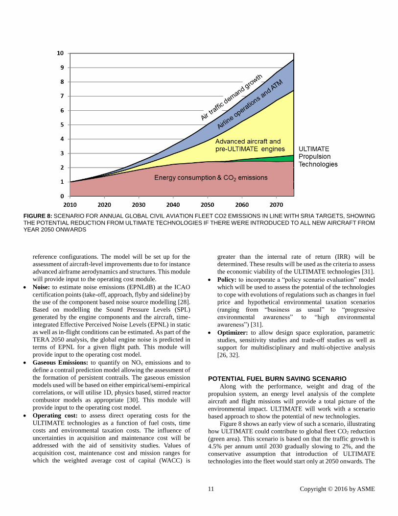
FIGURE 8: SCENARIO FOR ANNUAL GLOBAL CIVIL AVIATION FLEET CO2 EMISSIONS IN LINE WITH SRIA TARGETS, SHOWING
THE POTENTIAL REDUCTION FROM ULTIMATE TECHNOLOGIES IF THERE WERE INTRODUCED TO ALL NEW AIRCRAFT FROM YEAR 2050 ONWARDS
reference configurations. The model will be set up for the
assessment of aircraft-level improvements due to for instance
advanced airframe aerodynamics and structures. This module
will provide input to the operating cost module.
Noise: to estimate noise emissions (EPNLdB) at the ICAO
certification points (take-off, approach, flyby and sideline) by
the use of the component based noise source modelling [28].
Based on modelling the Sound Pressure Levels (SPL)
generated by the engine components and the aircraft, time-
integrated Effective Perceived Noise Levels (EPNL) in static
as well as in-flight conditions can be estimated. As part of the
TERA 2050 analysis, the global engine noise is predicted in
terms of EPNL for a given flight path. This module will
provide input to the operating cost model.
Gaseous Emissions: to quantify on NOx emissions and to
define a contrail prediction model allowing the assessment of
the formation of persistent contrails. The gaseous emission
models used will be based on either empirical/semi-empirical
correlations, or will utilise 1D, physics based, stirred reactor
combustor models as appropriate [30]. This module will
provide input to the operating cost model.
Operating cost: to assess direct operating costs for the
ULTIMATE technologies as a function of fuel costs, time
costs and environmental taxation costs. The influence of
uncertainties in acquisition and maintenance cost will be
addressed with the aid of sensitivity studies. Values of
acquisition cost, maintenance cost and mission ranges for
which the weighted average cost of capital (WACC) is
greater than the internal rate of return (IRR) will be
determined. These results will be used as the criteria to assess
the economic viability of the ULTIMATE technologies [31].
Policy: to incorporate a “policy scenario evaluation” model
which will be used to assess the potential of the technologies
to cope with evolutions of regulations such as changes in fuel
price and hypothetical environmental taxation scenarios
(ranging from “business as usual” to “progressive
environmental awareness” to “high environmental
awareness”) [31].
Optimizer: to allow design space exploration, parametric
studies, sensitivity studies and trade-off studies as well as
support for multidisciplinary and multi-objective analysis
[26, 32].
POTENTIAL FUEL BURN SAVING SCENARIO Along with the performance, weight and drag of the
propulsion system, an energy level analysis of the complete
aircraft and flight missions will provide a total picture of the
environmental impact. ULTIMATE will work with a scenario
based approach to show the potential of new technologies.
Figure 8 shows an early view of such a scenario, illustrating
how ULTIMATE could contribute to global fleet CO2 reduction
(green area). This scenario is based on that the traffic growth is
4.5% per annum until 2030 gradually slowing to 2%, and the
conservative assumption that introduction of ULTIMATE
technologies into the fleet would start only at 2050 onwards. The
12 Copyright © 2016 by ASME
graph shows that the CO2 reductions from improved operations
and ATM and the improvements from projected aircraft and
engine technologies will not by themselves be sufficient to
stabilize fleet emissions. The ULTIMATE technologies are
complementary to these projected developments and achieve
substantial additional CO2 reductions.
This scenario is based on the assumption that conventional
engine and airframe development will be able to continue
targeted rates of improvements until 2050, that the current
exponential growth of air traffic moderates, that ULTIMATE
technologies are not available prior to 2050, but they are
introduced progressively across the whole fleet in the next 25
years. They would then save over three billion tonnes of CO2
emissions in that period. However, faster traffic growth, a
slower pace of reference technology development, or earlier
phasing-in of selected ULTIMATE technologies would increase
the overall savings. ULTIMATE will study such accelerated
development scenarios.
Note that the ULTIMATE CO2 reductions will make it more
likely that limited supplies of environmentally efficient biofuels
would be sufficient to reach the overall ATAG goal of halving
the current rate of net CO2 emissions.
DISCUSSION AND CONCLUSION
A categorization of disruptive engine technology has been
introduced based on a lost work potential. This categorization
allows a structured concept development of ultra-efficient aero
engines. In association with this a number of radical technologies
have been discussed.
To allow a rational down-selection of disruptive technology
a simple partially quantitative metric has been proposed. Apart
from allowing a quantitative measure to be available early in a
research project, it also forces a project to exercise a number of
interrelated disciplines preparing the ground for more advances
mission analysis. This approach eases the transfer of models onto
the evaluation platform.
Introducing radical technology into aero engines is always
associated with balancing development risk against value
provided to the customer. The complexity of the core
technologies discussed requires propulsion architecture changes
at least as challenging as the introduction of the turbofan engine
in the late 1950s, but realising such concepts could unlock
significant environmental and competitive benefits for the
aviation industry.
ACKNOWLEDGMENTS This work is financially supported by the E.U. under the
“ULTIMATE – Ultra Low emission Technology Innovations for
Mid-century Aircraft Turbine Engines” Project co-funded by the
European Commission within the Horizon 2020 Programme
(2014-2020) under the Grant Agreement n° 633436.
REFERENCES
[1] European Commission, ”G. Technology readiness levels
(TRL),” HORIZON 2020 – WORK PROGRAMME
2014-2015 General Annexes, Extract from Part 19 -
Commission Decision C(2014)4995., [Online]. Available:
http://ec.europa.eu/research/participants/data/ref/h2020/w
p/2014_2015/annexes/h2020-wp1415-annex-g-
trl_en.pdf. [Använd August 2015].
[2] "Annual Report of the Council," International Civil
Aviation Organization, ICAO, 2012.
[3] B. Owen, "Fuel Efficiency Development and Prediction,"
Omega, 2008.
[4] IEA, "Key World Energy Statistics," International Energy
Agency, 2014.
[5] T. Andres and B. Boden. [Online]. Available:
http://cdiac.ornl.gov/ftp/ndp030/global.1751_2010.ems.
[Accessed August 2015].
[6] "Global Carbon Atlas," [Online]. Available:
http://www.globalcarbonatlas.org/?q=en/emissions.
[Accessed August 2015].
[7] ACARE, "Realising Europe's vision for aviation, Strategic
Research & Innovation Agenda, Volume 1," Advisory
Council for Aviation Research and Innovation in Europe,
2012.
[8] S. W. Ashcraft, A. S. Padron, K. A. Pascioni, G. W. Stout
och D. L. Huff, ”Review of Propulsion Technologies for
N+3 Subsonic Vehicle Concepts,” NASA/TM--2011-
217239, 2011.
[9] E. M. Greitzer, J. S. Hollman and W. K. Lord, N+3
Aircraft Concept Designs and Trade Studies, Volume I,
2010.
[10] T. Grönstedt, M. Irannezhad, L. Xu, O. Thulin and A.
Lundbladh, "First and Second Law Analysis of Future
Aircraft Engines," vol. 136, no. 3, 2014.
[11] S. Kaiser, A. Seitz, S. Donnerhack and A. Lundbladh, "A
Composite Cycle Engine Concept with Hecto-Pressure
Ratio," in Joint Propulsion Conference, Orlando, FL,
USA, 2015.
[12] P. L. Meitner, M. Boruta and J. Jerovsek, "The Nutating
Engine – Prototype Report and Test Results,"
NASA/TM—2006-214342, 2006.
[13] A. Perullo, D. N. Mavris and E. Fonseca, "An integrated
assessment of an organic Rankine cycle concept for use in
onboard aircraft power generation," in GT2013-95734,
San Antonio, Texas, USA, 2013.
[14] R. Avellan, A. Capitao Patrao, A. Lundbladh och T.
Grönstedt, ”Preparing for Proof-of-Concept of a Novel
Propeller for Open Rotor Engines,” i ISABE-2015-22083,
2015.
[15] A. Lundbladh, L. Larsson and T. Grönstedt,
"Transforming Propulsion Installation for Commercial
Aircraft," in ISABE-2013-1434, Busan, Korea.
[16] "Napier Nomad – An Engine of Outstanding Efficiency,"
Flightglobal, 1954. [Online]. Available:
13 Copyright © 2016 by ASME
http://www.flightglobal.com/pdfarchive/view/1954/1954
%20-%201201.html. [Accessed August 2015].
[17] S. Boggia and K. Rud, "Intercooled Recuperated Gas
Turbine Engine Concept," in AIAA 2005-4192, 2005.
[18] K. Yakinthos, D. Missirlis, A. Sideridis, Z. Vlahostergios,
O. Seite och A. Goulas, ”Modelling Operation of System
of Recuperative Heat Exchangers for Aero Engine with
Combined use of Porosity Model and Thermo-Mechanical
Model,” Engineering Applications of Computational
Fluid Mechanics, vol. 6, nr 4, pp. 608-621, 2012.
[19] R. Varvill och A. Bond, ”The Skylon spaceplane: progress
to realisation,” Journal of the British Interplanetary
Society, vol. 61, pp. 412-418, 2008.
[20] N. Yannakoulis, ”Introducing Inter-Turbine Reheat in a
High-Bypass Civil Turbofan Engine,” MSc Thesis,
Department of Power and Propulsion, Cranfield
University, UK, Cranfield, 2004.
[21] S. Brunner, S. Baber, N. Harris, N. Caldwell, K. Keding,
L. Rahrig och L. Pho, ”and,” NASA/CR-2010-216798,
NASA N+3 Subsonic Fixed Wing Silent Efficient Low-
Emissions Commercial Transport.
[22] J. Wolkovitch, ""The joined wing-An overview.","
Journal of Aircraft, vol. 23, no. 3, pp. 161-178., 1986.
[23] X. Zhao, O. Thulin och T. Grönstedt, ”First and Second
Law Analysis of Intercooled Turbofan Engine,” i GT2015-
43187, Montréal, Canada, 2015.
[24] ICCT, ”International Civil Aviation Organization's CO2
Certification Requirement for new Aircraft,” The
International Council on Clean Transportation, 2013.
[25] V. Sethi, R. Camilleri, R. Singh, P. Pilidis, S. Ogaji och C.
Celis, ”Energy Plant Selection and Asset Management
The TERA (Techno-Economic Enviromental Risk
Analysis,” i ISABE-2013-1429, 2013.
[26] K. Kyprianidis, ”Multi-disciplinary Conceptual Design of
Future Jet Engine Systems,” PhD Thesis, School of
Engineering, Cranfield University, 2010.
[27] V. Sethi, A. Nind, G. Doulgeris, P. Pilidis, M. Doussinault,
P. Cobas och A. Rueda, ”"The map fitting tool
methodology: gas turbine compressor off-design
performance modeling,” Journal of Turbomachinery, vol.
135, nr 6, 2013.
[28] T. Grönstedt, A. Dax, K. Kyprianidis och S. Ogaji, ”Low-
Pressure System Component Advancements and its
Influence on Future Turbofan Engine Emissions”, , pp.
505-516,,” i ASME Turbo Expo, GT2009-59950, Orlando,
FL, USA, 2009.
[29] P. Lolis, S. Arumagam, V. Sethi och P. Pilidis , ”New
Empirical Aero Engine Gas Turbine Preliminary Weight
Estimation Method Based On Artificial Neural
Networks,” i 71st SAWE Conference, Bad Goegging,
2012.
[30] B. Khandelwal, ”Development of Gas Turbine Combustor
Preliminary Design Methodologies and Preliminary
Assessments of Advanced Low Emission Combustor
Concepts,” PhD Thesis, School of Engineering, Cranfield
University, 2012.
[31] D. Nalianda, ”Impact of Environmental Taxation Policies
on Civil Aviation - A Techno-Economic Environmental
Risk Assessment,” PhD Thesis, School of Engineering,
Cranfield University, , 2012.
[32] P. Bellocq, V. Sethi, A. Patin, S. Capodanno och F.
Rodriguez, ”Advanced 0-D Performance Modelling of
Counter Rotating Propellers for Multi-Disciplinary
Preliminary Design Assessments of Open Rotors,” ASME
TURBO EXPO 2014, GT-2014-27141, 2014.
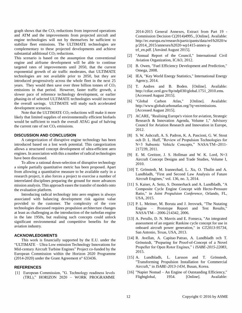
APPENDIX Key performance data of the year 2015 state of the art engine
is found in Table 1 below. Corresponding calculations of lost
work potential are found in Table 2.
TABLE 1. PERFORMANCE FOR YEAR 2015 ENGINE. ALL
DATA IN CRUISE OPERATING POINT. GIVEN EFFICIENCIES ARE POLYTROPIC.
Overall pressure ratio 41.2
Bypass ratio 13.3
Fan pressure ratio (outer stream) 1.415
Fan pressure ratio (inner stream) 1.274
Fan mass flow (kg/s) 443.2
Fan efficiency (outer stream) 91.8%
Intermediate pressure compressor
pressure ratio
5.45
Intermediate pressure compressor
efficiency
91.5%
High pressure compressor pressure
ratio
5.94
High pressure compressor efficiency 92.1%
High pressure turbine efficiency 90.7%
Intermediate pressure turbine
efficiency
91.0%
Low pressure turbine efficiency 91.3%
SFC (mg/Ns) 14.18
Cruise 𝜂𝑡ℎ𝑒𝑟𝑚𝑎𝑙 49.6%
Cruise 𝜂𝑝𝑟𝑜𝑝𝑢𝑙𝑠𝑖𝑣𝑒 .81.6%
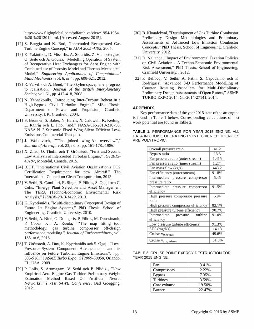
TABLE 2. CRUISE POINT EXERGY DESTRUCTION FOR
YEAR 2015 ENGINE.
Fan 3.41%
Compressors 2.22%
Bypass 7.35%
Turbines 3.59%
Core exhaust 19.50%
Burner 22.47%