UK Protective Marking: UK HPR1000 · UK Protective Marking: Not Protectively Marked Rev: 000 Page:...
32
Transcript of UK Protective Marking: UK HPR1000 · UK Protective Marking: Not Protectively Marked Rev: 000 Page:...
UK HPR1000
GDA
Preliminary Safety Report Chapter 2 General Plant Description
UK Protective Marking: Not Protectively Marked
Rev: 000 Page: 2 / 32
UK Protective Marking: Not Protectively Marked
DISTRIBUTION LIST Recipients Cross Box
GNS Executive ☐
GNS all staff ☐
GNS and BRB all staff
CGN
EDF
Regulators ☒
Public ☒
☒
☒
☒

UK HPR1000
GDA
Preliminary Safety Report Chapter 2 General Plant Description
UK Protective Marking: Not Protectively Marked
Rev: 000 Page: 3 / 32
UK Protective Marking: Not Protectively Marked
SENSITIVE INFORMATION RECORD
Section Number
Section Title Page Content Category

UK HPR1000
GDA
Preliminary Safety Report Chapter 2 General Plant Description
UK Protective Marking: Not Protectively Marked
Rev: 000 Page: 4 / 32
UK Protective Marking: Not Protectively Marked
Table of Contents
2.1 List of Abbreviations and Acronyms ................................................... 5
2.2 Introduction .......................................................................................... 9
2.3 Evolution of the HPR1000 Design ...................................................... 9
2.4 Main Technical Characteristics .......................................................... 16
2.4.1 General Description of the Plant ....................................................... 16
2.4.2 Brief Introduction to Main Plant Systems ........................................ 19
2.4.2.1 Reactor Core and Reactor Coolant System ...................................... 19
2.4.2.2 Safety Systems .................................................................................. 20
2.4.2.3 Main Auxiliary Systems ................................................................... 22
2.4.2.4 Steam and Power Conversion Systems ............................................. 23
2.4.2.5 Instrumentation & Control Systems ................................................. 24
2.4.2.6 Electric Power Systems .................................................................... 24
2.5 Operating Modes ................................................................................ 24
2.6 Layout of the Main Civil Structures .................................................. 25
2.7 References .......................................................................................... 30
2.8 Appendix ............................................................................................ 30
Appendix A ................................................................................................... 31

UK HPR1000
GDA
Preliminary Safety Report Chapter 2 General Plant Description
UK Protective Marking: Not Protectively Marked
Rev: 000 Page: 5 / 32
UK Protective Marking: Not Protectively Marked
2.1 List of Abbreviations and Acronyms
ACPR1000 Advanced Chinese Pressurized Reactor
APG Steam Generator Blowdown System [SGBS]
ARE Main Feedwater Flow Control System [MFFCS]
ASG Emergency Feedwater System [EFWS]
ASP Secondary Passive Heat Removal System [SPHRS]
ATE Condensate Polishing System [CPS]
BDA Emergency Diesel Generator Building A
BDB Emergency Diesel Generator Building B
BDC Emergency Diesel Generator Building C
BDU SBO Diesel Generator Building for Train A
BDV SBO Diesel Generator Building for Train B
BEJ Extra Cooling System and Firefighting System Building
BEX Equipment Access Building
BFX Fuel Building
BJX Auxiliary Transformer Platform
BLX Conventional Island Electrical Building
BMX Turbine Generator Building
BNX Nuclear Auxiliary Building
BOP Balance of Plant
BPA Essential Service Water Pump Station A
BPB Essential Service Water Pump Station B
BRX Reactor Building
BSA Safeguard Building A
BSB Safeguard Building B
BSC Safeguard Building C
BTA Main Transformer Platform
BWX Radioactive Waste Treatment Building

UK HPR1000
GDA
Preliminary Safety Report Chapter 2 General Plant Description
UK Protective Marking: Not Protectively Marked
Rev: 000 Page: 6 / 32
UK Protective Marking: Not Protectively Marked
CDF Core Damage Frequency
CGN China General Nuclear Power Corporation
CI Conventional Island
CPR1000 Chinese Pressurized Reactor
CPR1000+ Chinese Improved Pressurized Reactor
CRF Circulating Water System [CWS]
DCS Digital Control System
DEC Design Extension Condition
ECS Extra Cooling System [ECS]
EDE Annulus Ventilation System [AVS]
EHR Containment Heat Removal System [CHRS]
EUF Containment Filtration and Exhaust System [CFES]
EUH Containment Combustible Gas Control System [CCGCS]
EUR European Utility Requirements
FCG Fangchenggang Nuclear Power Plant
FCG Unit 3 Fangchenggang Nuclear Power Plant Unit 3
GCT Turbine Bypass System [TBS]
GDA Generic Design Assessment
HPR1000 Hua-long Pressurized Reactor
HPR1000 (FCG3)
Hua-long Pressurized Reactor under Construction at Fangchenggang Nuclear Power Plant Unit 3
HVAC Heating, Ventilation and Air Conditioning System
HYH Hongyanhe Nuclear Power Plant
I&C Instrumentation and Control
IAEA International Atomic Energy Agency
IVR In-Vessel Retention
IRWST In-Containment Refueling Water Storage Tank
KDA Severe Accident I&C System [SA I&C]
KDS Diverse Actuation System [DAS]

UK HPR1000
GDA
Preliminary Safety Report Chapter 2 General Plant Description
UK Protective Marking: Not Protectively Marked
Rev: 000 Page: 7 / 32
UK Protective Marking: Not Protectively Marked
LA Ling’ao Nuclear Power Plant
LHSI Low Head Safety Injection
LOCA Loss of Coolant Accident
LRF Large Release Frequency
MCR Main Control Room
MHSI Medium Head Safety Injection
MSRCV Main Steam Relief Control Valve
MSRIV Main Steam Relief Isolation Valve
ND Ningde Nuclear Power Plant
NI Nuclear Island
NNSA National Nuclear Safety Administration
NPP Nuclear Power Plant
NSSS Nuclear Steam Supply System
ONR Office for Nuclear Regulation
OPEX Operating Experience
PCSR Pre-Construction Safety Report
PMC Fuel Handling and Storage System [FHSS]
PSA Probabilistic Safety Assessment
PSR Preliminary Safety Report
PTR Fuel Pool Cooling and Treatment System [FPCTS]
PWR Pressurized Water Reactor
RBS Emergency Boration System [EBS]
RCCA Rod Cluster Control Assembly
RCP Reactor Coolant System [RCS]
RCV Chemical and Volume Control System [CVCS]
REA Reactor Boron and Water Makeup System [RBWMS]
REN Nuclear Sampling System [NSS]
RHR Residual Heat Removal

UK HPR1000
GDA
Preliminary Safety Report Chapter 2 General Plant Description
UK Protective Marking: Not Protectively Marked
Rev: 000 Page: 8 / 32
UK Protective Marking: Not Protectively Marked
RIS Safety Injection System [SIS]
RPV Reactor Pressure Vessel
RPF Reactor Pit Flooding
RRI Component Cooling Water System [CCWS]
SADV Severe Accident Dedicated Valve
SBO Station Black Out
SEC Essential Service Water System [ESWS]
SG Steam Generator
SGTR Steam Generator Tube Rupture
SSCs Structures, Systems and Components
SSE Safe Shutdown Earthquake
TEP Coolant Storage and Treatment System [CSTS]
URD Utility Requirements Document
UK United Kingdom of Great Britain and Northern Ireland
UK HPR1000 The UK version of the Hua-long Pressurized Reactor
VDA Atmospheric Steam Dump System [ASDS]
VVP Main Steam System [MSS]
WENRA Western European Nuclear Regulators Association
YJ Yangjiang Nuclear Power Plant
System codes (XXX) and system abbreviations (YYY) are provided for completeness in the format (XXX [YYY]), e.g. Steam Generator Blowdown System (APG [SGBS]).

UK HPR1000
GDA
Preliminary Safety Report Chapter 2 General Plant Description
UK Protective Marking: Not Protectively Marked
Rev: 000 Page: 9 / 32
UK Protective Marking: Not Protectively Marked
2.2 Introduction
This chapter supports the following high level objective: the UK HPR1000 design will be developed in an evolutionary manner, using a robust design process, building on relevant good international practice, to achieve a strong safety and environmental performance.
This chapter will demonstrate the following:
a) The design for HPR1000 reflects modern international relevant good practice and operating experience (OPEX) from similar power plants under construction or operation;
b) Main novel features associated with the design will be identified and explained.
This chapter, which briefly describes the HPR1000 (FCG3) technology, comprises the following sub-chapters:
a) Sub-chapter 2.3 describes evolution of the HPR1000 design.
b) Sub-chapter 2.4 provides the main technical characteristics of the HPR1000 (FCG3). Sub-chapter 2.4.1 describes the unit briefly and sub-chapter 2.4.2 presents the main systems.
c) Sub-chapter 2.5 introduces all permitted operating modes of the HPR1000 (FCG3).
d) Sub-chapter 2.6 gives a high level introduction to the layout of main civil structures. A design drawing showing the general layout of nuclear island and conventional island of the HPR1000 (FCG3) is also included in this sub-chapter.
2.3 Evolution of the HPR1000 Design
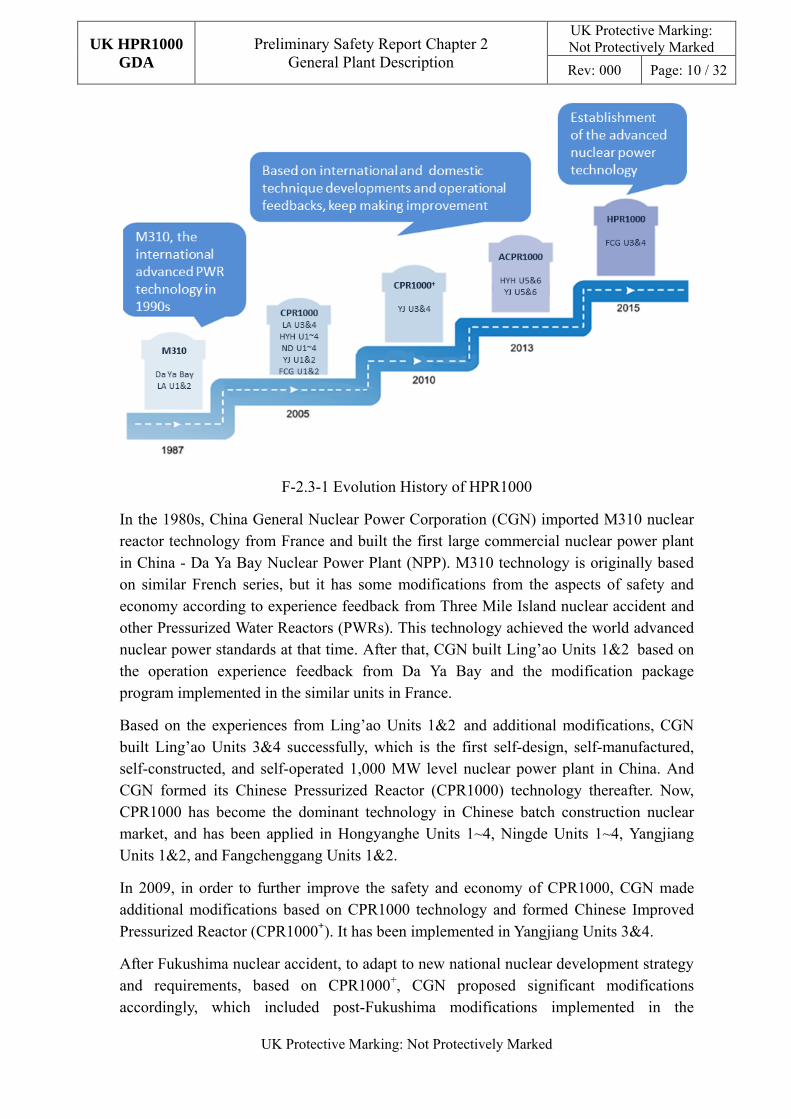
The HPR1000 has a strong pedigree. It is developed based on improvements of the design of a series of successful Chinese commercial Nuclear Power Plant (NPP) designs. The evolution history of HPR1000 is shown in F-2.3-1.
UK HPR1000
GDA
Preliminary Safety Report Chapter 2 General Plant Description
UK Protective Marking: Not Protectively Marked
Rev: 000 Page: 10 / 32
UK Protective Marking: Not Protectively Marked
F-2.3-1 Evolution History of HPR1000
In the 1980s, China General Nuclear Power Corporation (CGN) imported M310 nuclear reactor technology from France and built the first large commercial nuclear power plant in China - Da Ya Bay Nuclear Power Plant (NPP). M310 technology is originally based on similar French series, but it has some modifications from the aspects of safety and economy according to experience feedback from Three Mile Island nuclear accident and other Pressurized Water Reactors (PWRs). This technology achieved the world advanced nuclear power standards at that time. After that, CGN built Ling’ao Units 1&2 based on the operation experience feedback from Da Ya Bay and the modification package program implemented in the similar units in France.
Based on the experiences from Ling’ao Units 1&2 and additional modifications, CGN built Ling’ao Units 3&4 successfully, which is the first self-design, self-manufactured, self-constructed, and self-operated 1,000 MW level nuclear power plant in China. And CGN formed its Chinese Pressurized Reactor (CPR1000) technology thereafter. Now, CPR1000 has become the dominant technology in Chinese batch construction nuclear market, and has been applied in Hongyanghe Units 1~4, Ningde Units 1~4, Yangjiang Units 1&2, and Fangchenggang Units 1&2.
In 2009, in order to further improve the safety and economy of CPR1000, CGN made additional modifications based on CPR1000 technology and formed Chinese Improved Pressurized Reactor (CPR1000+). It has been implemented in Yangjiang Units 3&4.
After Fukushima nuclear accident, to adapt to new national nuclear development strategy and requirements, based on CPR1000+, CGN proposed significant modifications accordingly, which included post-Fukushima modifications implemented in the

UK HPR1000
GDA
Preliminary Safety Report Chapter 2 General Plant Description
UK Protective Marking: Not Protectively Marked
Rev: 000 Page: 11 / 32
UK Protective Marking: Not Protectively Marked
constructing NPPs and extra significant modifications, formed its Advanced Chinese Pressurized Reactor (ACPR1000). These modifications were obtained from several aspects, such as conformance analysis with the current international rules and standards, Probabilistic Safety Assessment (PSA) result, experience feedback from Fukushima nuclear accident, etc. ACPR1000 technology is implemented in Yangjiang Units 5&6, and Hongyanhe Units 5&6.
CGN has developed the HPR1000 design based on the complete 30 years’ experience of NPP engineering, construction and OPEX. In line with Chinese regulations in Reference [1] and [2] and modern relevant good practice, the HPR1000 is an advanced nuclear plant technology. Also, HPR1000 has combined the advanced international NPP safety requirements, such as International Atomic Energy Agency (IAEA) Safety Standards in Reference [3], feedback from the Western European Nuclear Regulators Association (WENRA) documents in Reference [4], European Utility Requirements (EUR) in Reference [5] and other international codes and standards. A major advantage of the HPR1000 is that the OPEX learned from similar units worldwide has been integrated in the HPR1000 design from the basic design stage, including the lessons learned from Japanese Fukushima nuclear accident.
Furthermore, it is expected that the UK HPR1000 design will incorporate any additional changes to address specific UK site requirements and regulatory requirements.
The HPR1000 has been developed and evolved continuously through a series of improvements on NPP technologies with significant levels of optimization in order to improve and to enhance nuclear safety, as summarized in T-2.3-1 below.

UK HPR1000
GDA
Preliminary Safety Report Chapter 2 General Plant Description
UK Protective Marking: Not Protectively Marked
Rev: 000 Page: 12 / 32
UK Protective Marking: Not Protectively Marked
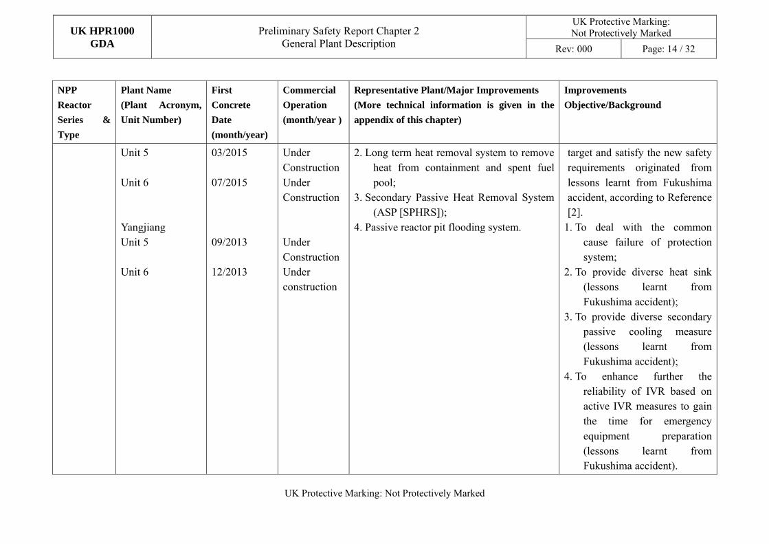
T-2.3-1 Evolution of CGN Reactors Fleet
NPP
Reactor
Series &
Type
Plant Name
(Plant Acronym,
Unit Number)
First
Concrete
Date
(month/year)
Commercial
Operation
(month/year )
Representative Plant/Major Improvements
(More technical information is given in the
appendix of this chapter)
Improvements
Objective/Background
M310 Da Ya Bay Unit 1 Unit 2 Ling’ao (LA) Unit 1 Unit 2
08/1987 04/1988 05/1997 11/1997
02/1994 05/1994 05/2002 01/2003
First introduction of French technology. ---
CPR1000
Ling’ao Unit 3 Unit 4 Hongyanhe Unit 1 Unit 2 Unit 3 Unit 4 Ningde Unit 1 Unit 2 Unit 3
12/2005 06/2006 08/2007 03/2008 03/2009 08/2009 02/2008 11/2008 01/2010
09/2010 08/2011 06/2013 05/2014 08/2015 09/2016 04/2013 05/2014 06/2015
LA Units 3&4: 1. Solid forging of Reactor Pressure Vessel
(RPV) core shell; 2. Optimized design of the reactor sump
filters; 3. Digital Control System (DCS); 4. Half-speed turbine; 5. Combustible gas control system.
Improvements were applied with consideration of international NPP operation feedbacks and batch modifications applied to similar French units. 1. To improve the integrity of
RPV; 2. Consideration of similar NPP
operation feedbacks from Sweden, France and the United States;
3. Consideration of advanced technology development and technique application of

UK HPR1000
GDA
Preliminary Safety Report Chapter 2 General Plant Description
UK Protective Marking: Not Protectively Marked
Rev: 000 Page: 13 / 32
UK Protective Marking: Not Protectively Marked
NPP
Reactor
Series &
Type
Plant Name
(Plant Acronym,
Unit Number)
First
Concrete
Date
(month/year)
Commercial
Operation
(month/year )
Representative Plant/Major Improvements
(More technical information is given in the
appendix of this chapter)
Improvements
Objective/Background
Unit 4 Yangjiang Unit 1 Unit 2 Fangchenggang Unit 1 Unit 2
09/2010 12/2008 06/2009 07/2010 12/2010
07/2016 03/2014 06/2015 01/2016 10/2016
similar reactor practice; 4. Better economy performance; 5. To improve the safety of
containment in severe accident.
CPR1000+ Yangjiang (YJ) Unit 3 Unit 4
10/2010 11/2012
02/2016 03/2017
YJ Units 3&4 1. Improvement in Main Control Room
(MCR) habitability; 2. Improvement in main feed water isolation; 3. Active reactor pit flooding.
Modified safety shortage and improved safety and economy performance to achieve advanced international safety level. 1. To overcome the shortfall of
M310 MCR habitability; 2. To enhance the effectiveness
of main feedwater isolation under accident condition;
3. To mitigate the consequence of severe accident.
ACPR1000 Hongyanhe (HYH)
HYH Units 5&6 1. Diverse Actuation System (KDS [DAS]);
New safety features are applied to reach the probabilistic safety
UK HPR1000
GDA
Preliminary Safety Report Chapter 2 General Plant Description
UK Protective Marking: Not Protectively Marked
Rev: 000 Page: 14 / 32
UK Protective Marking: Not Protectively Marked
NPP
Reactor
Series &
Type
Plant Name
(Plant Acronym,
Unit Number)
First
Concrete
Date
(month/year)
Commercial
Operation
(month/year )
Representative Plant/Major Improvements
(More technical information is given in the
appendix of this chapter)
Improvements
Objective/Background
Unit 5 Unit 6 Yangjiang Unit 5 Unit 6
03/2015 07/2015 09/2013 12/2013
Under Construction Under Construction Under Construction Under construction
2. Long term heat removal system to remove heat from containment and spent fuel pool;
3. Secondary Passive Heat Removal System (ASP [SPHRS]);
4. Passive reactor pit flooding system.
target and satisfy the new safety requirements originated from lessons learnt from Fukushima accident, according to Reference [2].
1. To deal with the common cause failure of protection system;
2. To provide diverse heat sink (lessons learnt from Fukushima accident);
3. To provide diverse secondary passive cooling measure (lessons learnt from Fukushima accident);
4. To enhance further the reliability of IVR based on active IVR measures to gain the time for emergency equipment preparation (lessons learnt from Fukushima accident).
UK HPR1000
GDA
Preliminary Safety Report Chapter 2 General Plant Description
UK Protective Marking: Not Protectively Marked
Rev: 000 Page: 15 / 32
UK Protective Marking: Not Protectively Marked
NPP
Reactor
Series &
Type
Plant Name
(Plant Acronym,
Unit Number)
First
Concrete
Date
(month/year)
Commercial
Operation
(month/year )
Representative Plant/Major Improvements
(More technical information is given in the
appendix of this chapter)
Improvements
Objective/Background
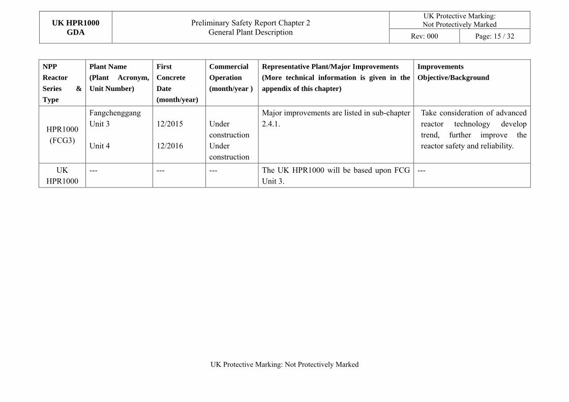
HPR1000 (FCG3)
Fangchenggang Unit 3 Unit 4
12/2015 12/2016
Under construction Under construction
Major improvements are listed in sub-chapter 2.4.1.
Take consideration of advanced reactor technology develop trend, further improve the reactor safety and reliability.
UK
HPR1000 --- --- --- The UK HPR1000 will be based upon FCG
Unit 3. ---

UK HPR1000
GDA
Preliminary Safety Report Chapter 2 General Plant Description
UK Protective Marking: Not Protectively Marked
Rev: 000 Page: 16 / 32
UK Protective Marking: Not Protectively Marked
2.4 Main Technical Characteristics
2.4.1 General Description of the Plant
CGN is both the reactor designer of the HPR1000, and an experienced nuclear power plant operator. Therefore, based on the OPEX and lessons learned from the international PWR plant design, construction and operation as well as from Fukushima nuclear accident, HPR1000 applies proven technologies into an integrated and innovative design. The design follows the requirements of Safety Regulations for Design of Nuclear Power Plants (HAF 102) in Reference [1], issued by Chinese National Nuclear Safety Administration (NNSA), and benchmarks the latest IAEA requirements in SSR2/1 in Reference [3].
The HPR1000 PWR utilizes well-proven basic technology similar to the majority of other NPPs currently in operation successfully worldwide. This PWR produces heat, raises steam, and is based on a primary system, a secondary system and a cooling system.
On the basis of CGN fleet evolution, HPR1000 is designed to be more robust and resilient, with three trains of physically separated safety systems and a powerful combination of active and passive safety systems. The safety, reliability and economic efficiency of the plant have been systematically improved. The HPR1000 (FCG3) design has the following major features:
a) The plant is designed to have a lifetime of at least 60 years to enhance economics;
b) The core is composed of 177 fuel assemblies to provide a lower core linear power density and to increase core thermal margin;
c) The Secondary Passive Heat Removal System (ASP [SPHRS]) is designed to remove the heat from the steam generators in the Design Extension Condition (DEC) of total loss of normal feedwater from Main Feedwater Flow Control System (ARE [MFFCS]) and emergency feedwater from Emergency Feedwater System (ASG [ EFS]);
d) Three trains of Component Cooling Water System (RRI [CCWS]) and Essential Service Water System (SEC [ESWS]) are provided as the heat sink. In addition, the Extra Cooling System (ECS [ECS]) is designed to provide a diverse backup heat sink in the extreme case of a total loss of the Component Cooling Water System (RRI [CCWS]) and Essential Services Water System (SEC [ESWS]), and is designed to remove heat from the containment and from spent fuel pool;
e) The Containment Heat Removal System (EHR [CHRS]) is designed to remove in-containment heat and to mitigate overpressure risk by spraying in severe accidents scenarios;
f) The Containment Filtration and Exhaust System (EUF [CFES]) is designed to mitigate containment overpressure risk in the event of the containment heat removal system failure;

UK HPR1000
GDA
Preliminary Safety Report Chapter 2 General Plant Description
UK Protective Marking: Not Protectively Marked
Rev: 000 Page: 17 / 32
UK Protective Marking: Not Protectively Marked
g) The Containment Combustible Gas Control System (EUH [CCGCS]) is designed to eliminate the hydrogen explosion risk in the event of severe accidents;
h) Severe Accident Dedicated Valves (SADVs) are designed to mitigate risk of high pressure core melting;
i) In line with modern defence-in-depth design principles, primary feed-bleed methodology is included to cool the reactor core in case of a total loss of secondary cooling;
j) There are multiple emergency power supply sources consisting of 3 trains of Emergency Diesel Generators (EDGs), 2 fixed Station Blackout Diesel Generators (SBO DGs), 1 mobile diesel generator, and large-capacity batteries and mobile power interfaces to enhance reliability and independence of power supply. The EDGs and SBO DGs are designed to be diverse by being manufactured by different manufacturers, having different design capacities and actuation modes (automatic for EDGs and manual for SBO DGs);
k) The plant is designed with a digital Instrumentation and Control (I&C) system and an advanced Main Control Room (MCR) to improve efficiency of operation;
l) The containment is designed to have a robust double-shell with a large free volume, which consists of one concrete outer shield and a pre-stressed reinforced concrete inner containment with a steel liner. The containment is resistant to the crash of a large commercial airplane.
Based on our understanding of UK context, combining with the assessment experience of other GDA projects, we recognized two potential novel features:
a) Secondary Passive Heat Removal System (ASP [SPHRS]): this system functions as a diverse backup line of secondary cooling in case of emergency feedwater failure. It removes the heat from steam generator by achieving natural circulation. This technique is sourced from secondary passive heat removal system of ACPR1000 PWRs (under construction at Hongyanhe Units 5&6). This system is composed of three trains, corresponding to three SGs. More description of ASP is given in sub-chapter 7.7 of the PSR;
b) Extra Cooling System (ECS [ECS]): this system provides a diverse heat sink in case of losing normal cooling chain. It cools the containment and spent fuel pool by mechanical draft cooling towers. This technique is sourced from the improvement of long term heat removal system to remove heat from containment and spent fuel pool of ACPR1000. More description of ECS [ECS] is given in sub-chapter 7.12 of the PSR.
The HPR1000 (FCG3) general design parameters are summarized in T-2.4-1.

UK HPR1000
GDA
Preliminary Safety Report Chapter 2 General Plant Description
UK Protective Marking: Not Protectively Marked
Rev: 000 Page: 18 / 32
UK Protective Marking: Not Protectively Marked
T-2.4-1 HPR1000 (FCG3) General Technical Parameters
No Parameters Unit Values
1 Plant Type --- 3-loop PWR
2 Operational Design Life Years 60
3 Safe Shutdown Earthquake (SSE) g 0.3
4 Equilibrium Refueling Cycle Length Months 18
5 Nominal Reactor Thermal Power MW 3150
6 Generator Electrical Output Power MW ≈1180
7 Plant Thermal Efficiency % 37
8 Core Damage Frequency (CDF) Target 1
/(reactor∙year)
<1×10⁻⁵
9 Large Release Frequency (LRF) Target 1
/(reactor∙year)
<1×10⁻⁶
10 Core Thermal Margin % >15
11 Minimum Response Time for Operator
Intervention1
minutes 30
12 Target Minimum Average Discharge Fuel
Assembly Burn-up
MWD/tU ≥47000
13 Nominal Temperature of Reactor Coolant
System
℃ 307.0
14 Design Pressure of Reactor Coolant System MPa abs 17.23
15 Design Temperature of Reactor Coolant
System
℃ 343.0
16 Nominal Pressure of Reactor Coolant MPa abs 15.5

UK HPR1000
GDA
Preliminary Safety Report Chapter 2 General Plant Description
UK Protective Marking: Not Protectively Marked
Rev: 000 Page: 19 / 32
UK Protective Marking: Not Protectively Marked
No Parameters Unit Values
System
17 Best Estimate Flowrate (single loop) m3/h 25450
18 Free Containment Volume m3 ≈75300
Note 1: In the HPR1000 (FCG3) design, the manual actions are permitted and are based on the following two principles: a) no manual action is permitted in the main control room until at least 30 minutes after the first significant information is transmitted to the operator; b) no local plant manual action is permitted until at least one hour after the first significant information is transmitted to the operator.
2.4.2 Brief Introduction to Main Plant Systems
This sub-section introduces very briefly the main systems of HPR1000 (FCG3), so as to give an overview of the plant, including:
a) Reactor core and reactor coolant system;
b) Safety systems;
c) Main auxiliary systems;
d) Steam and power conversion systems;
e) Instrumentation & control systems;
f) Electric power systems.
2.4.2.1 Reactor Core and Reactor Coolant System
The reactor core of the HPR1000 (FCG3) is composed of 177 fuel assemblies. Each fuel assembly consists of 1 fuel assembly skeleton and 264 fuel rods arranged in a 17×17 square matrix; the fuel rod consists of the cladding tube, the uranium dioxide fuel pellets, the end plugs and the pressure springs. 68 Rod Cluster Control Assemblies (RCCAs) are arranged in the reactor core and are used to control the core reactivity. Detailed information on the reactor core is given in Chapter 5.
The Reactor Coolant System (RCP [RCS]) of the HPR1000 (FCG3) consists of three cooling circuits or loops, one reactor vessel and one pressurizer. Each circuit consists of one reactor coolant pump, one SG and the primary pipes. The operational pressure of each circuit is 15.5 MPa abs. The RCP [RCS] transfers the heat produced by the reactor core to the secondary system through the SGs and supplies steam for the turbine generator set; the steam is produced in the secondary side of the SGs. Detailed information about the RCP [RCS] is given in Chapter 6.

UK HPR1000
GDA
Preliminary Safety Report Chapter 2 General Plant Description
UK Protective Marking: Not Protectively Marked
Rev: 000 Page: 20 / 32
UK Protective Marking: Not Protectively Marked
2.4.2.2 Safety Systems
The safety systems are the systems which perform safety functions to bring the plant into the safe state in incident or accident conditions. Safety systems of the HPR1000 (FCG3) are listed. Brief introductions for important systems are given below. A detailed description of these systems is given in Chapter 7.
a) Safety Injection System (RIS [SIS])
The RIS [SIS] is primarily used to provide emergency borated water injection for the reactor core and remove the heat of the reactor after the accident. The RIS [SIS] consists of three independent redundant trains (A, B and C). Each train, connected with the corresponding reactor coolant system (RCP [RCS]) loop, consists of the Medium Head Safety Injection (MHSI) subsystem, the Low Head Safety Injection (LHSI) subsystem, and the accumulator subsystem.
A detailed description of the RIS [SIS] is given in sub-chapter 7.3 of the PSR.
b) Emergency Boration System (RBS [EBS])
The RBS [EBS] is a safeguard system for borating the reactor core during accidents to compensate for the reactivity insertion due to core cooling. The RBS [EBS] consists of three independent trains. Each is composed of one emergency boric acid tank, one piston pump and the connection lines. The piston pump injects the boric acid solution (passing through the isolation valves of the containment and the isolation valves of the reactor coolant pressure boundary) into the cold leg lines of one loop of the RCP [RCS], and the RBS [EBS] shares with the RIS [SIS] the line used for injection into the RCP [RCS].
A detailed description of the RBS is given in sub-chapter 7.4 of the PSR.
c) Atmospheric Steam Dump System (VDA [ASDS])
The VDA [ASDS] can discharge steam from SG into atmosphere when the Turbine Bypass System (GCT [TBS]) is unavailable. The VDA [ASDS] consists of three discharge sequences of the same safety class (each SG corresponds to one train). Each train of the VDA [ASDS] is composed of one Main Steam Relief Isolation Valve (MSRIV), one Main Steam Relief Control Valve (MSRCV), located at the downstream of isolation valve, one silencer, located at the discharge piping at the downstream of MSRCV and connecting piping.
A detailed description of the VDA [ASDS] is given in sub-chapter 7.5 of the PSR.
d) Emergency Feedwater System (ASG [EFWS])
When the normal feedwater systems are unavailable, the ASG [EFWS] should provide emergency feedwater for the SGs so as to remove the residual heat. The ASG consists of three independent trains. Each train is composed of one water tank, one emergency feedwater pump and the valves and connection lines.

UK HPR1000
GDA
Preliminary Safety Report Chapter 2 General Plant Description
UK Protective Marking: Not Protectively Marked
Rev: 000 Page: 21 / 32
UK Protective Marking: Not Protectively Marked
A detailed description of the ASG [EFWS] is given in sub-chapter 7.6 of the PSR.
e) Secondary Passive Heat Removal System (ASP [SPHRS])
The ASP [SPHRS] is designed to provide decay heat removal during DEC accidents, as well as conditions where the Emergency Feedwater System (ASG [EFWS]) is failed. The ASP [SPHRS] performs the safety function by natural circulation. The ASP [SPHRS] consists of three identical cooling trains, which corresponds to the three SGs. Each train is composed of one inlet steam pipeline, one condensing heat exchanger, one condensing return pipeline and related valves.
A detailed description of the ASP [SPHRS] is given in sub-chapter 7.7 of the PSR.
f) Containment Heat Removal System (EHR [CHRS])
The EHR [CHRS] is designed to be a dedicated DEC mitigating system. In order to maintain the containment integrity during DEC conditions, the EHR [CHRS] transfers the decay heat from the containment atmosphere to the In-Containment Refuelling Water Storage Tank (IRWST) by containment spray, and to the ultimate heat sink eventually. During severe accidents, EHR [CHRS] injects enough borated water to the reactor pit for external cooling outside the RPV, keeping the molten core corium in the Reactor Pressure Vessel (RPV). The EHR [CHRS] consists of four subsystems, including containment spraying, reactor pit injection, strainer back-flushing and passive reactor pit injection.
A detailed description of the EHR [CHRS] is given in sub-chapter 7.8 of the PSR.
g) Containment Filtration and Exhaust System (EUF [CFES])
The EUF [CFES] is a dedicated severe accident mitigating system, which contributes to protect the containment. In the event of internal overpressure due to hypothetical severe accident sequences, EUF [CFES] relieves the containment pressure and minimizes the unavoidable releases of activity to the environment to an extent as low as possible. The main component of EUF [CFES] is the scrubbing unit, which consists of two separate filter vessels.
A detailed description of the EUF [CFES] is given in sub-chapter 7.9 of the PSR.
h) Containment isolation
The concept of containment isolation is addressed by containment isolation valves dispersed in mechanical fluid systems penetrating the containment. A detailed description of the containment isolation is given in sub-chapter 7.10 of the PSR
i) Containment Combustible Gas Control System (EUH [CCGCS])
The EUH [CCGCS] contributes to containment of radioactive substances by reducing the hydrogen concentration in the containment. This supports the maintenance of containment integrity and leak tightness following a Loss of Coolant Accident (LOCA) or DEC-B event. The EUH [CCGCS] consists of the hydrogen recombination subsystem

UK HPR1000
GDA
Preliminary Safety Report Chapter 2 General Plant Description
UK Protective Marking: Not Protectively Marked
Rev: 000 Page: 22 / 32
UK Protective Marking: Not Protectively Marked
and the hydrogen monitoring subsystem.
A detailed description of the EUH [CCGCS] is given in sub-chapter 7.11 of the PSR.
j) Extra Cooling System (ECS [ECS])
The ECS [ECS] performs as a diverse heat sink, which removes the core residual heat and the decay heat from the spent fuel pool under DEC-A conditions (such as total loss of cooling chain and station black out) and DEC-B conditions. The ECS [ECS] consists of two identical trains. Each train contains a terminal cooling loop and an intermediate cooling loop.
A detailed description of the ECS [ECS] is given in sub-chapter 7.12 of the PSR.
2.4.2.3 Main Auxiliary Systems
Auxiliary systems are the systems which are essential to maintain normal operation of the plant. The main auxiliary systems of HPR1000 (FCG3) are listed below. Brief introductions for important systems are given in this chapter. A detailed description of these systems is given in Chapter 10.
a) Chemical and Volume Control System (RCV [CVCS])
The RCV [CVCS]’s main functions are RCP [RCS] volume control, slow core reactivity control, RCP [RCS] water chemical control, and reactor coolant pump seal injection. It consists of six subsystems, including letdown subsystem, coolant purification subsystem, volume control and hydrogenation subsystem, chemical additives injection subsystem, charging subsystem and RCP [RCS] pump seal water injection and leak-off subsystem.
A detailed description of the RCV [CVCS] is given in sub-chapter 10.3 of the PSR.
b) Reactor Boron and Water Makeup System (REA [RBWMS])
The REA [RBWMS] assists RCV [CVCS] to perform slow core reactivity control function. It is structured in three parts: boric acid preparation and distribution, boric acid storage and makeup, and demineralized water makeup.
A detailed description of the REA [RBWMS] is given in sub-chapter 10.4 of the PSR.
c) Coolant Storage and Treatment System (TEP [CSTS])
A description of the TEP [CSTS] is given in sub-chapter 10.5 of the PSR.
d) Nuclear Sampling System (REN [NSS])
A description of the REN [NSS] is given in sub-chapter 10.6 of the PSR.
e) Fuel Handling and Storage System (PMC [FHSS])
A description of the PMC [FHSS] is given in sub-chapter 10.7 of the PSR.
f) Fuel Pool Cooling and Treatment System (PTR [FPCTS])

UK HPR1000
GDA
Preliminary Safety Report Chapter 2 General Plant Description
UK Protective Marking: Not Protectively Marked
Rev: 000 Page: 23 / 32
UK Protective Marking: Not Protectively Marked
The PTR [FPCTS] is designed for spent fuel pool cooling, purification, biological shielding, and water transfer operation between reactor pool and spent fuel pool. It consists of 5 parts: cooling loops for spent fuel pool, purification loops for spent fuel pool and reactor pool, skimming loops for spent fuel pool and reactor pool, water transfer loop, and filling and makeup loops.
A detailed description of the PTR [FPCTS] is given in sub-chapter 10.8 of the PSR.
g) Component Cooling Water Systems (RRI [CCWS])
A description of the RRI [CCWS] is given in sub-chapter 10.9 of the PSR.
h) Essential Service Water System (SEC [ESWS])
A description of the SEC [ESWS] is given in sub-chapter 10.10 of the PSR.
i) Heating, Ventilation and Air Conditioning System (HVAC)
A description of the HVAC is given in sub-chapter 10.11 of the PSR.
j) Firefighting Systems
A description of the firefighting systems is given in sub-chapter 10.12 of the PSR.
2.4.2.4 Steam and Power Conversion Systems
The steam and power conversion systems are designed to convert thermal energy produced by the Nuclear Steam Supply System (NSSS) into electrical power. The main steam and power conversion systems of the HPR1000 (FCG3) are listed below. Brief introductions for important systems are given in this chapter. A detailed description of these systems is given in Chapter 11.
a) Main Steam System (VVP [MSS])
The VVP [MSS] performs the main operation functions of removing decay heat by transferring steam to the condenser and isolating the main steam line to limit the cooling of the primary system in case of accidents. This system consists of the pipes and valves that take the steam from each steam generator to the main steam header.
A detailed description of the VVP [MSS] is given in sub-chapter 11.3 of the PSR.
b) Steam Generator Blowdown System (APG [SGBS])
A description of the APG [SGBS] is given in sub-chapter 11.4 of the PSR.
c) Main Feedwater Flow Control System (ARE [MFFCS])
The ARE [MFFCS] performs the main operation functions of maintaining the SG level to remove residual heat and isolating the main feedwater line to limit the cooling of the primary system in case of accidents. This system consists of the pipes and valves that supply feed water from the common feedwater header to the three steam generators.

UK HPR1000
GDA
Preliminary Safety Report Chapter 2 General Plant Description
UK Protective Marking: Not Protectively Marked
Rev: 000 Page: 24 / 32
UK Protective Marking: Not Protectively Marked
A detailed description of the ARE [MFFCS] is given in sub-chapter 11.5 of the PSR.
d) Circulating Water System (CRF [CWS])
A description of the CRF [CWS] is given in sub-chapter 11.6 of the PSR.
e) Turbine Bypass System (GCT [TBS])
A description of the GCT [TBS] is given in sub-chapter 11.7 of the PSR.
f) Condensate Polishing Plant (ATE [CPP])
A description of the ATE [CPP] is given in sub-chapter 11.8 of the PSR.
2.4.2.5 Instrumentation & Control Systems
Chapter 8 describes the advanced technology of digital control systems and the main control room designs which are used for the HPR1000 (FCG3) nuclear power plant. Instrumentation and control systems are specifically described in Chapter 8 as follow:
a) Safety category 1 function (FC1) I&C system;
b) Safety category 2 function (FC2) I&C system;
c) Safety category 3 function (FC3) and non-classified function (NC) I&C system;
d) Severe Accident I&C System (KDA [SA I&C]);
e) Diverse Actuation System (KDS [DAS]);
f) Main Control Room (MCR) system.
2.4.2.6 Electric Power Systems
The electric power systems are designed to supply power to the NPP and the equipment. The main electric power systems are listed as below. A detailed description of those systems is given in chapter 9.
a) Offsite electric power system;
b) Onsite electric power system;
c) Station Black Out (SBO) electric power system.
2.5 Operating Modes
Normal operation of the HPR1000 (FCG3) includes six standard reactor operating modes, from full power operation to cold shutdown. These six standard reactor modes are defined below:
a) Reactor power operation
In this mode, the reactor is either approaching critical or is critical, and is on the range of zero to full power operation. The reactor heat is transferred from the reactor core to the

UK HPR1000
GDA
Preliminary Safety Report Chapter 2 General Plant Description
UK Protective Marking: Not Protectively Marked
Rev: 000 Page: 25 / 32
UK Protective Marking: Not Protectively Marked
steam generators in the secondary loop. The reactor coolant system is full and the pressurizer is in two-phase.
b) Steam generator cooling normal shutdown
In this mode, the reactor is sub-critical. The residual heat from the reactor core is removed by the steam generators. The residual heat removal system is isolated from the primary loop. Reactor coolant system is full and the pressurizer is in two-phase.
c) RIS/RHR cooling normal shutdown
In this mode, the reactor is sub-critical. The residual heat removal system is connected to the primary loop. Reactor coolant system is full and the pressurizer is in single-phase or two-phase.
d) Maintenance cold shutdown
The draining, air sweeping and maintenance of the reactor coolant system are performed in the maintenance cold shutdown mode. The primary water level is higher than the minimum working water level of the residual heat removal system. The reactor pressure vessel head can be either closed or open in this mode.
e) Refueling cold shutdown
In this mode, the reactor pressure vessel head is removed. The primary loop is connected with the reactor pool. The refueling activities are performed in this mode.
f) Reactor complete defueling
In this mode, all the fuel assemblies are moved from the reactor core to the Fuel Building (BFX).
2.6 Layout of the Main Civil Structures
The HPR1000 (FCG3) adopts a single unit layout in order to increase the independency, and to achieve better site and power grid adaptability. The main block layout of the HPR1000 (FCG3) consists of the Nuclear Island (NI), the Conventional Island (CI) and Balance of Plant (BOP).
F-2.6-1 shows the general layout of key buildings of the HPR1000 (FCG3) NI and CI. The detailed layout, especially the BOP buildings, depends on the site-specific characteristics, and is not included in GDA.
The NI includes the Reactor Building (BRX), three Safeguard Buildings (BSA/BSB/BSC), the Fuel Building (BFX), the Nuclear Auxiliary Building (BNX), the Emergency Diesel Generator Buildings (BDA/BDB/BDC), the SBO Diesel Generator Buildings (BDU/BDV), the Radioactive Waste Treatment Building (BWX), etc.
The CI mainly includes the Turbine Generator Building (BMX), and the Conventional Island Electrical Building (BLX), Main Transformer Platform (BTA), Standby

UK HPR1000
GDA
Preliminary Safety Report Chapter 2 General Plant Description
UK Protective Marking: Not Protectively Marked
Rev: 000 Page: 26 / 32
UK Protective Marking: Not Protectively Marked
Transformer Platform (BTX), the Auxiliary Transformer Platform (BJX), etc. The CI is not described in detail in this document.
The most significant BOP structures include the Essential Service Water Pump Stations (BPA/BPB), the extra cooling system and Firefighting System Building (BEJ), etc.
The upper section of the Reactor Building (BRX), where the Reactor Coolant System (RCP [RCS]) is accommodated, is constituted of two concentric concrete shells. The inner is a pre-stressed concrete shell lined with steel plates, and the outer is a reinforced concrete shell. The space between the two shells is kept at a negative pressure by the Annulus Ventilation System (EDE [AVS]) to ensure leak tightness. A detailed description of BRX is given in sub-chapter 16.4.2 and 16.4.3 of the PSR.
The BRX is surrounded by the three Safeguard Buildings (BSA/BSB/BSC) and BFX. All these buildings share the same raft foundation. The vertical cross-sections of BRX, BSC and BFX are shown in F-2.6-2.
The three Safeguard Buildings (BSA/BSB/BSC) are located adjacent to the BRX, as shown in F-2.6-1. The safety systems are deployed in BSA/BSB/BSC, with their redundant trains strictly physically isolated within different building divisions. The NI electrical equipment and I&C equipment are also deployed in BSA/BSB/BSC. The Main Control Room (MCR) is located in BSC. The BRX and the BSC have been designed to be protected against large commercial aircraft crash.
The Equipment Access Building (BEX) is located adjacent to BSA.
The Fuel Building (BFX) is located adjacent to the BRX. Fuel from the operation, once the energy has been used, will be transported to and stored in the fuel building, before being moved to an interim spent fuel store. The interim spent fuel storage facilities are not included in FCG design scope. Whether these facilities are included in GDA documents is to be determined in GDA scope documents.
The Reactor Auxiliary Building (BNX), where the nuclear auxiliary systems are accommodated, is located adjacent to the BFX, as shown in F-2.6-1.
The Radioactive Waste Treatment Building (BWX) is located next to the BNX. In the HPR1000 (FCG3) site-specific plant layout, two units will share one waste treatment building. The UK design for the site specific licensing phase will consider this point.
The discharge stack is located adjacent to the BRX, as shown in F-2.6-1.
Three arrays of Emergency Diesel Generator Buildings (BDA/BDB/BDC) and two arrays of SBO Diesel Generator Buildings (BDU/BDV) are separately located on either side of the axis of the NI, to reduce the risk of common mode failure in external hazards.
The Turbine Generator Building (BMX), which is the main building of the CI, is located near the BSA/BSB/BSC. The Conventional Island Electrical Building (BLX), Main Transformer Platform (BTA), Standby Transformer Platform (BTX) and the Auxiliary
UK HPR1000
GDA
Preliminary Safety Report Chapter 2 General Plant Description
UK Protective Marking: Not Protectively Marked
Rev: 000 Page: 27 / 32
UK Protective Marking: Not Protectively Marked
Transformer Platform (BJX) are located to the side of the BMX.
For the HPR1000 (FCG3), the Essential Service Water Pump stations (BPA/BPB) are located adjacent to the coast. The specific locations and details of pump stations depend on the site-specific conditions, and are outside of the scope of GDA.
The extra cooling system and Firefighting System Building (BEJ) is adjacent to the BFX as shown in F-2.6-1. The BEJ houses the Extra Cooling System (ECS) and the firefighting systems, including the extra cooling towers, firefighting water pools, pumps and pipes.
A detailed description of nuclear island buildings is given in sub-chapter 16.4.4 of the PSR.
The description and layout design principles of the main civil structures are given in Chapter 16.

UK HPR1000
GDA
Preliminary Safety Report Chapter 2 General Plant Description
UK Protective Marking: Not Protectively Marked
Rev: 000 Page: 28 / 32
UK Protective Marking: Not Protectively Marked
F-2.6-1 General Layout of HPR1000 (FCG3)
At this stage, the generic site layout for UK HPR1000 is not completely defined, and it will be built based on the layout of FCG Unit 3

UK HPR1000
GDA
Preliminary Safety Report Chapter 2 General Plant Description
UK Protective Marking: Not Protectively Marked
Rev: 000 Page: 29 / 32
UK Protective Marking: Not Protectively Marked
F-2.6-2 Vertical cross-sections of BRX, BSC and BFX

UK HPR1000
GDA
Preliminary Safety Report Chapter 2 General Plant Description
UK Protective Marking: Not Protectively Marked
Rev: 000 Page: 30 / 32
UK Protective Marking: Not Protectively Marked
2.7 References
[1] NNSA, Safety Regulations for Design of Nuclear Power Plants, HAF 102, April 2004.
[2] NNSA, General Technical Requirement on NPP Improvement Action post-Fukushima (provisional), June 2012.
[3] IAEA, Safety Requirements: Safety of Nuclear Power Plant: Design, No.SSR-2/1, Revision 1, February 2016.
[4] WENRA, Safety of New NPP Designs, March 2013.
[5] EUR, European Utility Requirements for LWR Nuclear Power Plants, Revision D, October 2012.
2.8 Appendix
Appendix A: Explanations for Improvements in CGN Reactors Fleet Evolution.

UK HPR1000
GDA
Preliminary Safety Report Chapter 2 General Plant Description
UK Protective Marking: Not Protectively Marked
Rev: 000 Page: 31 / 32
UK Protective Marking: Not Protectively Marked
Appendix A
Explanations for Improvements in CGN Reactors Fleet Evolution
Explanations for improvements listed in T-2.3-1 are given below:
a) Major improvements of CPR1000:
1) Solid forging of Reactor Pressure Vessel (RPV) core shell: The irradiation damage level of joint weld material of RPV core shell resulted from fast neutron bombardment is generally higher than the one of base metal of core shell in the same irradiation environment. In order to ensure the integrity of RPV, the joint weld material of RPV core shell was cancelled by RPV core shell solid forging.
2) Optimized design of the reactor sump filters: The containment sump blockage rate of M310 is proved not conservative enough. In CPR1000 units, the sump filters’ performance is evaluated, and the sump filters are redesigned.
3) Digital Control System (DCS): Analogue C&I system was adopted in M310 NPPs, which became backward as network and computer technique were developed aggressively. Began with LA Unit3&4, Digital Control System (DCS) was applied in CPR1000 NPPs. The DCS is a mature technique, which improves the safety, reliability and flexibility of plants.
4) Half-speed turbine: The half-speed turbine delivers higher output with the same nuclear power level. This technology helps to improve the economy performance.
5) Combustible gas control system: Began with LA Unit3&4, combustible gas control system was added to consume the hydrogen produced during severe accidents. This improvement helps to avoid the risk of combustible gas blast.
b) Major improvements of CPR1000+:
1) Improvement in Main Control Room (MCR) habitability: The control room habitability system is optimazed to meet the requirement of NUREG-0800. The modification includes several systemic design improvements, such as the optimization on functional configuration of habitability area, re-definition the reasonable range of habitability area and so on.
2) Improvement in main feed water isolation: A non-seismically qualified simply check valve is substituted by a safety classified oleo-pneumatic gate valve in each main feedwater train, so that the safety level of feedwater isolation function is enhanced.
3) Active reactor cavity flooding: Active reactor cavity flooding is delivered by the Reactor Pit Flooding (RPF) system. RPF connected the firefight water pool with reactor cavity. In severe accident, the RPF delivered water into the reactor cavity with motor pumps to cool the outer side of the reactor pressure vessel to ensure the In-Vessel Retention (IVR). The melt reactor core is contained in the RPV to avoid releasing.
UK HPR1000
GDA
Preliminary Safety Report Chapter 2 General Plant Description
UK Protective Marking: Not Protectively Marked
Rev: 000 Page: 32 / 32
UK Protective Marking: Not Protectively Marked
c) Major improvements of ACPR1000:
1) Diverse actuation system: Diverse actuation system is added to mitigate the common cause failures of digitalization protection system.
2) Long term heat removal system to remove heat from containment and spent fuel pool: A dedicated system is added to remove residual heat from core and spent fuel pool in long term of a Station Black Out (SBO) accident. This modification is made in consideration of Fukushima’s feedback.
3) Secondary passive heat removal system: A secondary passive heat removal system is designed to remove the heat from the steam generators in SBO. Three independent loops are equipped to three SGs. Water in the loop is evaporated by heat of SGs and condensed in heat exchanger in one common water tank. This improvement is made in consideration of Fukushima’s feedback.
4) Passive reactor cavity flooding system: Passive reactor cavity flooding system fills the reactor cavity through a passive way, which ensures In-Vessel Retention (IVR) after the severe accident and prevents the radioactive material from being released to the environment. This system is composed of pressurized water tank and pips, which are arranged in a dedicated building in nuclear island.