
UINCLA S S I F lED 408 607 - Defense Technical … S S I F lED AD 408 607 ... upset forging billets...
45
UINCLA S S I F lED AD 408 607 DEFENSE DOCUMENTATION CENTER FOR SCIENTIFIC AND TECHNICAL INFORMATION CAMERON STATION, ALEXANDRIA. VIRGINIA UN(CLASSIFIED
Transcript of UINCLA S S I F lED 408 607 - Defense Technical … S S I F lED AD 408 607 ... upset forging billets...

UINCLA S S I F lED
AD 408 607
DEFENSE DOCUMENTATION CENTERFOR
SCIENTIFIC AND TECHNICAL INFORMATION
CAMERON STATION, ALEXANDRIA. VIRGINIA
UN(CLASSIFIED

NOTICE: 'Wen government or other drawings, speci-fications or other data are used for any purposeother than in connection with a definitely relatedgovernment procurement operation, the U. S.Government thereby incurs no responsibility, nor anyobligation whatsoever; and the fact that the Govern-ment may have formulated, furnished, or in any waysupplied the said drawings. specifications, or otherdata is not to be regarded by implication or other-wise as in any manner licensing the holder or anyother person or corporation, or conveying any rightsor permission to manufacture, use or sell anypatented invention that may in any way be relatedthereto.

AMC T2 7.466 (V) AMC NItMW TOO"
01 Woetern *e*r Report No 035-214 MAY 194$
(0
H9 HGH ENERGY RATE FORGING DEVELOPMENT
"J. M. Palsulich
- 1C. ..
.,Western Gear Corporation
• . ,Systems Management Division
&Precision Forge Co.
(Forging Subcontractor)
Contract. AF 33 (600)-42523
AMC Project TR 7-866
Fifth Interim Technical Progress Report
. 10 October 1962 - 10 May 1963
"DC
S- JUL 17l
AMC Aeronautical Systems Center
Air Material Command
1 United States Air Peroe
Wrlght-l4atterson Air Force Base, Ohio
4. .

!
Western Gear Report No. 635-214 AMC TR 7-866 (V)May 1963
HIGH ENERGY RATE FORGING DEVELOPMENT
J. M. Palsulich
WESTERN GEAR CORPORATIONSystems Management Division
andPrecision Forge Company
(Forging Subcontractor)
Contract: AF 33(600)-42523AMC Project: TR 7-866 (V)
ASD Project Engineer: L. C. Polley
Fifth Interim Technical Progress Report10 October 1962 - 10 May 1963
AMC Aeronautical Systems CenterUnited States Air Force
Wright-Patterson Air Force BaseDayton, Ohio
I
ABSTRACT - SUMMARY
Successful high energy rate forging of unwrought refractory materials ishighly dependent upon the forging configuration and die design. Good forgingsare possible when working stresses are compressive in nature. Tensileand shear stresses during forging generally result in fracturing of the billetif the refractory metals have received little or no plastic work.
Data for forging conditions and results of metallurgical examinations arepresented.
LYNWOOD ' CALIFORNIA
!m mvj6&
FOREWORD
This Interim Technical Progress Report covers a portion of the work onPhase MI performed under Contract AF 33(600)-42523 from October 1962to May 1963. It is published for technical information only, and does notnecessarily represent the recommendations, conclusions or approval ofthe Air Force.
This program is being conducted by the Systems Management Division ofWestern Gear Corporation, Lynwood, California. It is under the directionof Mr. L. C. Polley of the ASD Basic Industry Branch, Wright-PattersonAir Force Base, Ohio. Mr. J. M. Palsulich, Research Metallurgist isproject engineer and technical supervisor. Mr. M. L. Headman, Managerof Research is program manager.
ii
LYNWOOD W CALIFORNIA
I
NOTICES
When Government drawings, specifications or other data are used for anypurpose other than in connection with a definitely related Governmentprocurement operation, the United States Government thereby incurs noresponsibility nor any obligation whatsoever; and the fact that the Govern-ment may have formulated, furnished, or in any way supplied the saiddrawings, specifications, or other data, is not to be regarded by implica-tion or otherwise as in any manner licensing the holder or any otherperson or corporation, or conveying any rights or permission to manu-facture, use or sell any patented invention that may in any way be relatedthereto.
Copies of AMC Technical Reports should not be returned to the AMCAeronautical Systems Center unless return is required by security con-siderations, contractual obligations or notice on a specific document.
iii
LYNWOOD A CALIFORNIA
!
TABLE OF CONTENTS
Page
INTRODUCTION 1
Program Objective 1
Phase I - State-of-the Art Analysis 2
Phase H - Forging of Low and Medium Temperature Alloys 2
Phase III - Forging of Two Refractory Metals 2
DISCUSSION OF PHASE 111 3
Results 3
I. Billet Material Examination 3
H. Closed Die Forging 5
III. Micro-Examination of Forgings 8
CONCLUSIONS 11
iv
LYNWOOD CALIFORNIA

LIST OF TABLES
Table Number
I Analysis of Tungsten and TZM MolybdenumBillets 4
II Forging Conditions for TZM MolybdenumAhloy Rocket Nozzle Inserts 7
in Forging Conditions for Tungsten RocketNozzle Inserts 9
LIST OF FIGURES
Figure Number
1 Macroetch arc-melted tungsten billet 12
2 Photomicrograph of forged, pressed andsintered TZM molybdenum alloy 13
3 Photomicrograph of forged, pressed andsintered TZM molybdenum alloy 13
4 Photomicrograph of forged, pressed andsintered TZM molybdenum alloy 14
5 Photomicrograph of forged, pressed andsintered TZM molybdenum alloy 14
6 Photomicrograph of forged, pressed andsintered TZM molybdenum alloy 15
7 Photomicrograph of forged, pressed andsintered TZM molybdenum alloy 15
8 Photomicrograph of forged, pressed andsintered TZM molybdenum alloy 16
9 Photomicrograph of forged, pressed andsintered TZM molybdenum alloy 16
10 Photomicrograph of as-received TZMpressed and sintered billet 17
v
LYNWOOD w CALIFORNIA

Ii LIST OF FIGURES - (Continued)
Figure Number
11 Photomicrograph of as-received tungstenpressed and sintered billets 17
12 High energy rate forged TZM molybdenum
rocket nozzle insert 18
13 Arc melted TZM rocket nozzle insert 19
14 Pressed and sintered TZM rocket nozzle insert 19
15 Macroetched section of arc melted TZM billetin blocked condition 20
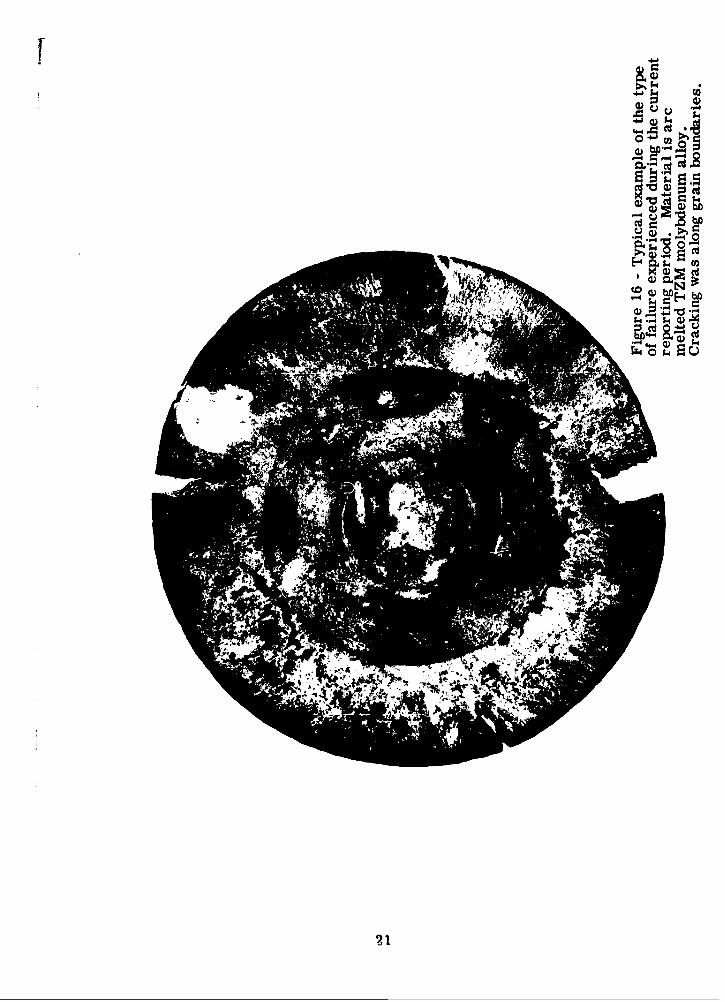
16 Typical example of failure in arc melted TZMmolybdenum alloy. 21
17 Typical example of failure in arc melted TZMmolybdenum alloy 22
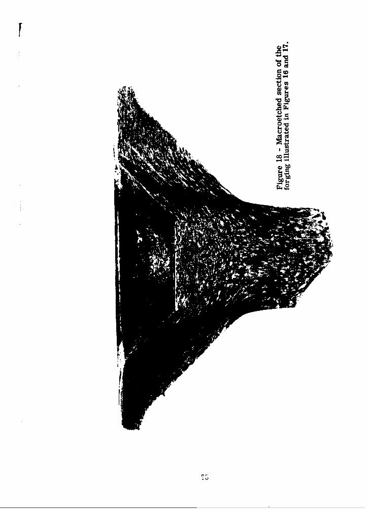
18 Macroetched section of the forging illustratedin Figures 16 and 17 23
19 Macroetched section of blocked tungsten forging 24
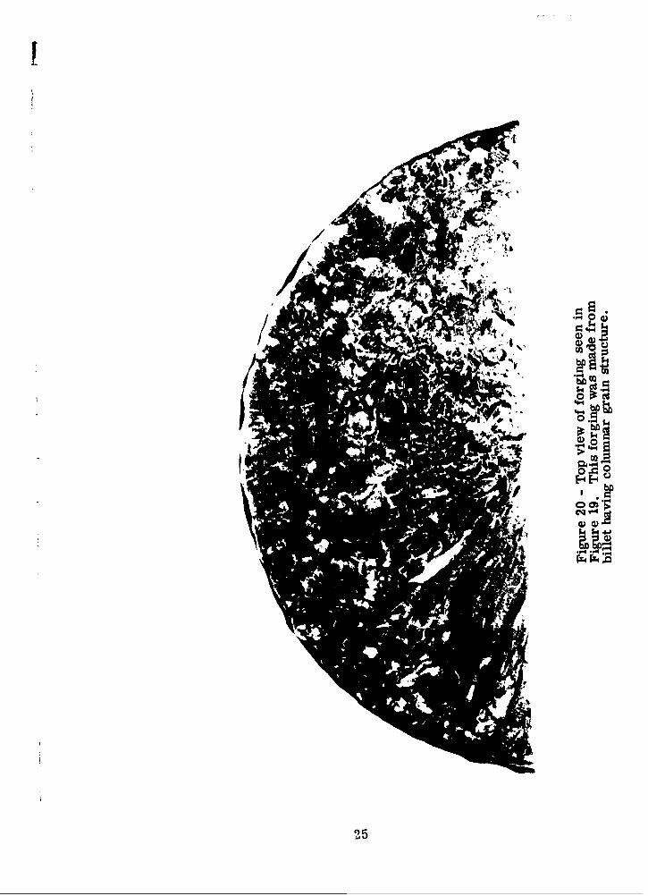
20 Top view of forging seen in Figure 19 25
21 Example of intragranular type cracking 26
22 Example of intragranular type cracking 26
23 Photomicrograph of banded area 27
24 Photomicrograph of as-forged, Group I, arcmelted TZM forging 27
25 Photomicrograph of as-forged, Group I, arcmelted TZM forging 28
26 Photomicrograph of as-forged, Group I, arcmelted TZM forging 28
27 Photomicrograph of pressed and sintered TZMbillet forged in Group I1 29
vi
LYNWOOD _ CALIFORNIA
!
INTRODUCTION
The refractory metals are a group of materials which generally includethose metals whose melting points are equal to, or higher than, 34007F.There are many refractory metals with widely varying properties andavailability. At the present time, these metals are the subject of inten-sive investigation because their high temperature strengths and highmelting points are required in space vehicles, advanced aircraft, andnuclear energy applications. For various economic and technologicalreasons the refractory metals currently of most importance are tungsten,tantalum, molybdenum, niobium and chromium.
The production, fabrication and machining of the refractory ne talspresent major problems which result in elevated costs. Using presentlyaccepted forging and manufacturing techniques, as much as 350 poundsof material are required to make a 35 pound part. Therefore any improve-ment in forging technique that can provide better material utiAzation willresult in greater efficiency of the forging process and provide substantialcost savings. These cost savings are possible through reduction of initialmaterial costs and substantial reduction in the cost of machining tofinished dimension.
This investigation of high energy rate forged refractory materials wasprompted by the demonstrated ability of the high velocity forging processto produce close tolerance precision forgings while providing bettermaterial utilization. Effective utilization of the process is also enhancedby the fact that forging temperature for a given material can be reducedto within the furnace capabilities of most companies in the metalworkingfield.
All forging in this program is being performed on a 1220 B Dynapak highenergy rate forging machine manufactured by the Advanced ProductsDepartment of General Dynamics Corporation. This report discusses theexperimental results obtained during the reporting period from 10 October1962 to 10 May 1963.
Program Objective
The objective of this program is to determine the suitability of the highenergy rate forging process using a Dynapak machine for the productionof aerospace hardware. The investigation includes a variety of materialsof current interest. Emphasis is placed on evaluating the metallurgicalstructure and the mechanical properties of the materials when forgingparameters are varied. Information on die design, forging temperature,mechanical properties, hardness, microstructures and other pertinentmaterial and manufacturing data will be developed.
1
LYN WOOD W CALIFORNIA

Phase I - State-of-the Art Analysis
During this phase, a state-of-the art survey was conducted to determinecurrent activity in high velocity pneumatic forging. During this phase,a satisfactory procedure for subsequent phases was established.
Phase II - Forging of Low and Medium Temperature Alloys
Under this phase, high velocity forging of the following materials was -studied: 6 Al-4V alpha-beta titanium alloy; AISI 4340 medium alloy steel;type H-11 tool steel; and PH 15-7 Mo precipitation hardening stainlesssteel. Phase H was divided into two sections: upset forging billets toapproximately 80% reduction, and the forging of specific geometries.
Phase II - Forging of Two Refractory Metals
This phase is to investigate the possibility of forging commercially puretungsten and TZM molybdenum alloy to close tolerances and to determinethe various forging parameters necessary to insure high quality forgings.After forging parameters have been established, subsequent forging ofspecific geometries will be accomplished.
2
LYNWOOD , CALIFORNIA

DISCUSSION OF PHASE III
Materials and Procedure
Two materials are currently being investigated under Phase III of theprogram, i. e., commercially pure tungsten and the TZM molybdenumalloy. Pressed-and-sintered and arc melted-and-centrifugally castbillets of both tungsten and TZM molybdenum alloy are used as startingmaterial. All billets have the nominal dimensions of two inches in dia-meter by two inches long. The arc melted billets were ultrasonicallyinspected and all were sound. Both the pressed and sintered and arcmelted billets were found to be free from any surface cracks whenexamined by the dye penetrant inspection method. Chemical analysis ofthe billets as supplied by the vendors is shown in Table I.
During this reporting period work continued on developing forging tech-niques to forge these materials into a rocket nozzle insert as shown inFigure 12. All billets were heated to forging temperature in a Lindbergrecirculating gas-fired furnace. Heating was accomplished without theuse of a protective atmosphere since it was previously established thatmetal losses due to oxidation were relatively low (under 3%).
Subsequent to forging, all parts were placed in lime to prevent rapidcooling and cracking. Stress relieving and recrystallization was performedunder an argon atmosphere in a Pereco glo-bar furnace.
The rocket nozzle inserts were forged in two stages. Blocking was per-formed using a flat punch and the finisher bottom die. Finishing wasperformed with the bottom die used in the blocking operation and a punchthat conformed to the I. D. dimensions of the finished part.
It should be noted that both the TZM molybdenum arc melted and centri-fugally cast billets and the TZM alloy pressed and sintered billets usedin this program had never been produced before and were considered ex-perimental by the suppliers.
Results
I. Billet Material Examination
Many problems occurred during the development forging of the rocketnozzle configuration. Generally speaking, the blocking operation pre-sented very few difficulties. However, in most cases, severe crackingoccurred during finish forging of the blocked parts. The following pro-cedures were observed:
3
LYNWOOD _ CALIFORNIA

Ltn
E-4)
00
0
4)-
~N *E--4
00
4) 4
00 01- 0000 0u,00
e.4q cq s4 k ) 0z 00-N~o *. N z wc
!
A. Macro-Examination
Macro-examination of the arc melted tungsten and TZM billetsdisclosed a columnar grain structure at one end of the billet andthe equi-axed grains at the other end (Figure 1). Most of the billetshad been forged before this fact was discovered. Upon checkingwith the supplier, it was learned that seven tungsten and sevenTZM molybdenum alloy billets could have been in this condition.All of the TZM alloy billets with the columnar structure and allbut one of the tungsten billets were forged.
Grain size of the as-received pressed and sintered billets rangedbetween 4 and 6 on the ASTM ferrous grain size charts (Figures10 and 11). The arc melted tungsten grains were between 1/16 inchand 1/32 inch in diameter and some of the columnar grains were3/4 inch long. Grains in the arc melted TZM molybdenum billetswere slightly smaller than those in the arc melted tungsten billets.
B. Micro -examination
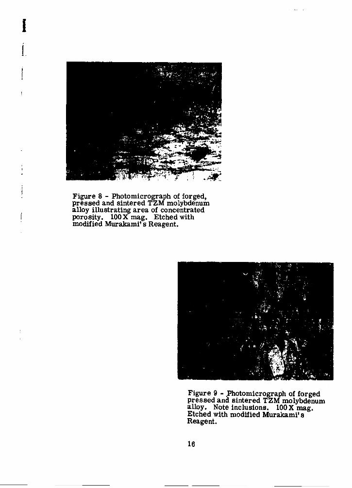
An extensive micro-examination of the forged pressed and sinteredTZM alloy parts showed a large number of inclusions and manyareas of porosity (Figures 2-9). Hardness of the inclusions wasdetermined on a Wilson microhardness tester utilizing a 100 gramweight. The average Knoop hardness of the particles was 900.This roughly corresponds to a Rockwell C hardness of 67. It isthought that these particles may be a titanium carbide. However,no analysis was performed to verify this.
I. Closed Die Forging
A. TZM Molybdenum
In the previous reporting period, the program had met with a largedegree of success. Sound forgings having a wall thickness of approxi-mately 0.090 inch were produced from both arc melted and pressedand sintered billets (Figures 12, 13 and 14). These forgings wereproduced in the following manner.
Blocking was performed in one blow using a fire pressure of 900psi, 6-3/8 inch stroke, and 22007F forging temperature, Theblocked forgings (Figure 15) were then cooled in lime to roomtemperature. Next, the forgings were heated to 20507F and strucktwo to three blows in the finisher dies with a fire pressure of 400psi. Reheating was performed between each blow. This procedureresulted in sound forgings approximately 80% of the time (Figures12, 13 and 14).
5
LYNWOOD W CALIFORNIA
During the present reporting period, a new approach was taken. Itwas decided to lower the forging temperature during the blockingoperation to 21007F and use two to three blows of low energy toblock the parts.
Group 1. Three arc-cast billets were struck three blows in thebloceRf die with a fire pressure of 450 psi and a forging tempera-ture of 21007F. * There was no evidence of cracking after the first,second or third blows. The same procedure was repeated for threepressed and sintered billets. One of the pressed and sintered billetscracked on the third blow. The part that cracked bounced out of thedie as it was being struck.
The finisher die was placed in the machine and one of the pressedand sintered billets was struck at 19507F with a fire pressure of500 psi. It exhibited severe radial cracking through the flash zoneand into the body to the forging. Next, the forging temperature wasincreased to 2050MF keeping the fire pressure at 500 psi. Thisforging cracked in the same manner as the previous one. Main-taining the 20507F forging temperature, the next three forgingswere struck blows at 400 psi. One of the three cracked radiallythrough the flash (Figures 16, 17 and 18).
Two forgings out of the original six were sound at this time. Usinga forging temperature of 20507F and a fire pressure of 400 psi, bothparts were struck. The wall thickness at this time was approximately0. 120 inch. It was decided to give each part one final blow at 500psi fire pressure in order to reduce the wall thickness to 0. 100 inch.Both forgings severely cracked during this operation.
Group H. Two arc cast and two pressed and sintered TZM molyb-denum ailoy billets were struck three blows in the blocker die usinga fire pressure of 600 psi and a forging temperature of 21000F. Allblocked forgings were sound. The forgings were then stress relievedat 25007F for one hour. All of the stress relieved forgings werestruck in the finishing dies utilizing a forging temperature of 2100°Fand a fire pressure ot 500 psi. Two of the forgings cracked. Oneof the remaining two was restruck under the above conditions. Thisforging also cracked. The other forging was struck onanother dayusing an incorrect bottom die. This incorrect die was identical tothe one being utilized on this program except that the diameter wasapproximately 3/4 inch smaller. Five tungsten and three TZMmolybdenum alloy billets were blocked in this small die. The re-sults of using this small die are discussed elsewhere in this report.
Group Hf. Two arc melted and one pressed and Sintered were blockedusing two blows at 750 psi fire pressure at 21007F. The forgings weresubsequently stress relieved for one hour at 25007F under an argon
* Reheating is performed 6
between blows in all cases.
LYNWOOD W CALIFORNIA

As u~~
____~~~ __ _ _ __0i j
00 0 5N 04 0o m- 4 4
cc~00O 0 0 0 0 0 0 -- - -.M NN. ~ C4 E C NN 14 94e N N 4 vN M 44 M
0 C
8 8 80. 88
C4 Cgs sg C-3. N C44 s4N e
0 .x
NN NN N 01 NN N tN0 ~ ~ ~ I F. I._________________________________
I ~ -- - -7

atmosphere. Next, the blocked forgings were struck with thefinisher dies. The pressed and sintered part cracked and thearc melted ones held together. When the arc melted partswere restruck they fractured on one side. The fire pressurefor both blows was 500 psi and the forging temperature was 21000F.
All three billets were struck in blocking and finishing using theincorrect small diameter bottom die. It would be expected that thebillets would rupture with the small die especially when the finisherpunch was used.
The billet material was subject to extremely high shear loading atthe entrance to the die due to the action of the punch and the under-size die.
Most of the other failures that were noted previously were locatedin the flash area and at the top of the forging. All of the failuresoccurring in conjunction with the undersize die went well into the bodyof the forgings.
B. Commercially Pure Tungsten
For the most part, the tungsten closed die forging was unsuccess-ful. Blocking could be successfully carried out without any exter-nal signs of rupturing. All blocking of tungsten billets during thisreporting period was carried out at 2600°F using a fire pressure of1000 psi and a stroke of 8-1/2 inches.
Some of the blocked forgings were sectioned and macroetched. Bothintracrystalline and intercrystalline cracks were evident (Figure 19).This was found to be true in both the pressed and sintered and arcmelted materials.
Recrystallization of the blocked forgings made little difference inthe forging characteristics of the materials. As long as the billetsare subjected to compressive stress, little or no surface rupturingis observed. Once the parts are subjected to tensile or shearstresses, however, severe rupturing occurs in almost every instance.
It is believed that the use of wrought billet stock made little differ-ence in this forging program. The presence of columnar grains(Figure 20) in some of the arc melted billets were also detrimentalto the forging characteristics. In the majority of cases, the tungstenforgings had many cracks whereas the TZM forgings had only oneor two cracks of limited length.
31I. Micro-Examination of Forgings.
Samples for micro-examination were taken from most of the forgings.All specimens were removed using an abrasive cut-off saw with copious
8
LYNWOOD WA CALIFORNIA

-,C 0 0•,•
Lo L
SI • 1 - "E
Q4
,G 11
4I

I
amounts of water for cooling. Both the tungsten and the TZM molybdenumalloy samples were etched subsequent to final polishing with a modifiedMurakami's Reagent (25% glycerol - 75% Murakami' s Reagent).
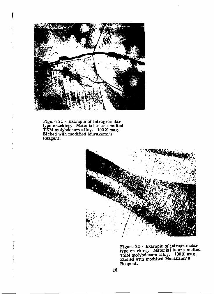
Figures 21 and 22 illustrate the intragranular type cracking noted in manyof the failures. The material is forged arc melted TZM molybdenumalloy. It should be noted that the grain boundaries were very fine anddid not present any obstacle to cracking. The banding that is visible wasnot observed in all forgings, nor was it in any of the as-received billetsthat were sectioned. Figure 23 is a view of the banded areas at 1000X.In any given crystal, there are banded areas as well as non-banded areas.
Specimens were removed from one of the Group I arc melted TZM forgings.The specimens were forged at 21007F and heat treated at 2300°F and23507F in some recrystallization primarily around the grain boundariesfor three hours resulted in some recrystallization primarily around thegrain boundaries and a small amount in the center of the crystals.
The pressed and sintered TZM billet forged in Group MI was given a2500°F heat treatment after forging. Only a small amount of recrystalli-zation was observed and this was principally in the grain boundaries(Figure 27). All the forgings made from pressed and sintered billetsshowed very little, if any, evidence of recrystallization.
10
LYNWOOD _ CALIFORNIA

CONCLUSIONS
High energy rate closed die forging of unwrought refractory metalsappears feasible providing the working stress in the part is compressivein nature. When the forging configuration is such that the principalstresses are tensile and/or shear, the forging of unwrought refractorymetals is not practical. This conclusion is in conflict with the one con-tained in Interim Report IV in which it was stated that it would be practi-cal to manufacture rocket nozzle inserts using unwrought arc castmaterials.
It is believed that the compressive working of unwrought billets prior toforging would eliminate the problem of cracking due to tensile or shearworking stress. This alternative could be evaluated with the die con-figuration utilized in this program.
The columnar grain structure found in some unwrought arc cast materialsis very detrimental in the forging process. The use of extruded or rolledbillets would obviate this condition. It is believed that high inclusion con-tent and porosity in the pressed and sintered TZM molybdenum contributeto rupturing of the forgings. The use of arc cast and extruded billetsshould help to eliminate this problem.
11
LYNWOOD CALIFORNIA

I
f
,og
12

I
Figure 2 - Photomicrograph of forgedpressed and sintered TZM molybdenumalloy. Note inclusions. 10OX mag.Etched with modified Murakami' sReagent
Figure 3 - Photomicrograph of forgedpressed and sintered TZM molybdenumalloy. Note inclusions. 10OX mag.Etched with modified Murakamil sReagent
13

!
Figure 4 - Photomicrograph of forged,pressed and sintered TZM molybdenumalloy illustrating area of concentratedporosity. 100 X mag. Etched withmodified Murakami' s Reagent.
Figure 5 - Photomicrograph of forgedpressed and sintered TZM molybdenumalloy. Note inclusions. 1OOX mag.Etched with modified Murakami' sReagent.
14

Figure 6 - Photomicrograph of forgedpressed and sintered TZM molybdenumalloy. Note inclusions. 10OX mag.Etched with modified Murakamil sReagent.
Figure 7 - Photomicrograph of forgedpressed and sintered TZM molybdenumalloy. Note inclusions. 10X mag.Etched with modified Murakami' sReagent.
15
!
¶ Figure 8 - Photomicrograph of forged,pressed and sintered TZM molybdenumalloy illustrating area of concentratedporosity. 100X mag. Etched withmodified Murakamil s Reagent.
Figure 9 - Photomicrograph of forgedpressed and sintered TZM molybdenumalloy. Note inclusions. 100X mag.Etched with modified Murakami' sReagent.
16

IVIA
Fiue1 - Phtmcoraho s
received tunsMe pressed and sintered~billet. 100 X mag. Etched with~modified Murakamil s Reagent.
17

I
i--18
0 0
So
r -
18

!
Figure 13 - Arc melted TZM billetforged into rocket nozzle insert shownin the as-forged condition.
Figure 14 - Pressed and sintered TZMbillet forged into rocket nozzle insertshown in the as-forged condition.
19

00
200
f.
Cd*
loNp!.
.. .ý'
P.14

cw~
o
u~ .d
F4o c4E d
pr ItAt,
22
0~
4-J4
)-'

.- I
G) cd
r34o o
24
255
I
Figure 21 - Example of intragranulartype cracking. Material is arc meltedTZM molybdenum alloy. 10OX mag.Etched with modified Murakamil sReagent.
' . • ý, NI-.*';,":" t
Figure 22 - Example of intragranulartype cracking. Material is arc meltedTZM molybdenum alloy. 10OX mag.Etched with modified Murakami'sReagent.
26

Figure 23 - Photomicrograph of bandedarea in forged TZM arc melted material.1000 X mag. Etched with modifiedMurakamil s Reagent.
Figure 24 - As-forged, Group I, arcmelted TZM forging. 10OX mag.Etched with modified Murakami' sReagent.
27

J
Figure 25 - As-forged, Group I,arc melted TZM forging heated at23507F for two hours subsequent toforging. 1OOX mag. Etched withmodified Murakami' s Reagent.
Figure 26 - As-forged, Group I arcmelted TZM forging heated at 23507Ffor three hours. Small amount of re-crystallization observed primarilyalong grain boundaries. 10OX mag.Etched with modified Murakami' s
28 Reagent.

F
Figure 27 - Pressed and sintered TZMbillet forged in Group MI. Heated to2500°F for one hour. Very small grainsdetected along grain boundaries. 1000Xmag. Etched with modified Murakami'sReagent.
29

J
DISTRIBUTION LISTContract AF 33(600)-42523
ASD (ASCRT-1) ASD (ASRCEE, Mr. J. Teres)Wright-Patterson AFB, Ohio (6) Wright-Patterson AFB, Ohio
ASD (ASAPT) ASD (ASRC, Dr. A. L. Lovelace)Wright-Patterson AFB, Ohio Wright-Patterson AFB, Ohio
ASD (ASRCEM-1A, Mrs. N. Ragen) ASD (ASRCMP-4, Mr. S. Inouye)Wright-Patterson AFB, Ohio (2) Wright-Patterson AFB, Ohio
Aerojet-General Corporation Aircraft Industries AssociationAttn: Chief Engineer Attn: Mr. H. D. MoranP.O. Box 298 7660 Beverly BoulevardAzusa, California Los Angeles 36, California
Allegheny Ludlum Steel Corporation Alloyd Research CorporationAttn: Works Manager Attn: Mr. Louis Mager, General Mgr.Brackenridge, Pennsylvania 202 Arsenal Street
Watertown 72, Massachusetts
Arcturus Manufacturing Corporation Armour Research FoundationAttn: Chief Engineer Attn: Metals Research Department4301 Lincoln Boulevard 10 West 35th StreetVenice, California Chicago 16, Illinois
ASTIA Babcock & Wilcox CompanyArlington Hall Station Attn: Chief MetallurgistArlington 12, Virginia (10) Beaver Falls, Pennsylvania
Baldwin- Lima-Hamilton Battelle Memorial InstituteAttn: Mr. George Lessie Defense Metals Information Center111 Fifth Avenue 505 King AvenueNew York 3, New York Columbus 1, Ohio
Bell Aerospace Corporation Bendix Products DivisionAttn: Manager, Production Engrg. Bendix Aviation CorporationP.O. Box 482 Attn: Director of EngineeringFort Worth 1, Texas 401 N. Bendix Drive
South Bend, Indiana
Bendix Utica Division Beryllium Corporation of AmericaBendix Aviation Corporation Attn: Mr. John D. Carr, LibrarianAttn: Director of Engineering P.O. Box 1462211 Senard Avenue Reading, PennsylvaniaUtica, New York
The Boeing Company Buehler CorporationMaterials Mechanics & Structures Attn: Works Manager
Branch - Systems Mgmt. Office 9000 Precision DriveP.O. Box 3707 Indianapolis 28, IndianaSeattle 24, Washington LYNWOOD , CALIFORNIA
LYNWOOD ALIFORNI

M4SMAW 6"tw
Cameron Iron Works Canton Drop Forging & Mfg. CompanyAttn: Manager, Special Products Div. Attn: Quality Control ManagerP.O. Box 1212 2100 Wilett AvenueHouston 1, Texas Canton 2, Ohio
Chance Vought Corporation The Cleveland Twist Drill CompanyAttn: Chief Librarian Attn: R. D. Lesher, Development Engr.P.O. Box 5907 1242 E. 59th StreetDallas, Texas Cleveland 14, Ohio
General Dynamics Corporation/Pomona General Dynamics Corporation/ConvairAttn: Chief, Mfg. Engineering Attn: Manufacturing DevelopmentP.O. Box 1011 General OfficePomona, California San Diego 12, California
General Dynamics Corporation/Convair General Dynamics Corp/AstronauticsAttn: Manufacturing Development Attn: Materials Research GroupZone P-46 Mail Zone 595-20Fort Worth, Texas San Diego 12, California
Curtiss-Wright Corporation Curtiss DivisionWright Aeronautical Division Curtiss-Wright CorporationAttn: Manager, Metallurgy Attn: Chief, Engineering MaterialsWood Ridge, New Jersey U. S. Route 46
Caldwell, New Jersey
Curtiss-Wright Corporation Defense Automotive Supply CenterMetals Processing Division Attn: DASC-PSB, Mr. W. SutherlandAttn: Chief Engineer 1501 Beard Street760 Northland Avenue Detroit 9, MichiganP.O. Box 15Buffalo, New York
Douglas Aircraft Company, Inc. Douglas Aircraft Company, Inc.Attn: Plant Engineering Supervisor Attn: Works Manager3855 Lakewood Boulevard 3000 Ocean Park BoulevardLong Beach 8, California Santa Monica, California
Douglas Aircraft Company, Inc. Dresser Industries, Inc.Attn: Works Manager Attn: Mr. George H. Pfefferle2000 North Memorial Drive Republic National Bank BuildingTulsa, Oklahoma Dallas, Texas
Dresser Industries, Inc. Firth Sterling, Inc.Security Engineering Division Attn: Manager, Powder Metals ResearclAttn: Mr. Ralph H. Hughes 3113 Forbes AvenueVice President - Manufacturing Pittsburgh 30, Pennsylvania3400 West IllinoisDallas 11, Texas
LYNWOOD V CALIFORNIA

!-7
Ford Motor Company General Electric CompanyAeronutronics Division Alloy Studies UnitAttn: Mr. R. L. Shanower Attn: Manager, Metallurgical Engineering1406 Talbott Tower ARO Building 200, FPLDDayton 2, Ohio Cincinnati 15, Ohio
Grumman Aircraft Engineering Corp. Harvey Aluminum, Inc.Attn: Manufacturing Research Attn: Technical Director
Coordinator Plant 12 19200 South Western AvenueBethpage, Long Island, N. Y. Torrance, California
The Hermes Corporation Interstate Drop Forge CompanyAttn: Mr. R. Q. Parsons, V. P. 4051 North 27th Street1243 Transit Milwaukee 16, WisconsinPomona, California
Kropp Forge Company Kelsey Hayes CompanyAttn: Ray Kropp Attn: Director of Research5301 Roosevelt Road Metals DivisionChicago 50, Illinois New Hartford, New York
Kelsey-Hales Company Ladish CompanyUtica Division Attn: Works ManagerAttn: Mr. Phillip E. Munson 5481 Packard AvenueUtica 4, New York Cudahy, Wisconsin
Ladish-Pacific Latrobe Steel CompanyAttn: Mr. G. Shaffer Attn: Mr. George F. Reuss3321 E. Slauson Avenue Engineering DepartmentLos Angeles 58, California Latrobe, Pennsylvania
Lear-Seigler, Inc. Lockheed Aircraft Corporation1700 East Grand Avenue Missile Systems DivisionEl Segundo, California Attn: Chief Engineer
Sunnyvale, California
Lockheed Aircraft Corporation Lycoming DivisionCalifornia Division AVCO Manufacturing CorporationAttn: Director of Engineering Attn: Chief Manufacturing EngineeringP.O. Box 511 Stratford, ConnecticutBurbank, California
The Marquardt Corporation The Marquardt CorporationAttn: Mr. Gene Kline Attn: Supt. of ManufacturingManufacturing Engineer 16555 Saticoy StreetP.O. Box 670 Van Nuys, CaliforniaOgden, Utah
The Martin Company Materials Advisory BoardDenver Division Attn: Executive DirectorAttn: Materials Engineering 2101 Constitution AvenueMail No. L-8 Washington, D.C.Denver 1, ColoradoWahntD.CLYNWOOD W CALIFORNIA
McDonnell Aircraft Corporation The Megadyne CorporationAttn: Chief Industrial Engineer Attn: Chief EngineerLambert - St. Louis Airport 12021 Vose StreetP.O. Box 516 North Hollywood, CaliforniaSt. Louis 3, Missouri
National Academy of Sciences National Bureau of StandardsNational Research Council Mr. A. BrennerAttn: Mary W. Brittain Mr. W. E. ReidSecretary to Mr. Arnquist Washington 25, D.C.2101 Constitution AvenueWashington 25, D.C.
New York University North American Aviation, Inc.College of Engineering Los Angeles DivisionAttn: Director, Research Division Attn: Section Head MaterialsNew York 53, N. Y. International Airport
Los Angeles 45, California
North American Aviation, Inc. Department of the NavyAttn: Chief Metallurgist Bureau of Naval Weapons3400 East 5th Street Attn: Mr. N. E. PromiselColumbus, Ohio Washington 25, D.C.
Norair Division Pacific Forge IncNorthrop Corporation Attn: Walter Sebasta, V. P. & Chief Eng.Attn: Mr. R. R. Nolan, V. P. Mfg. 10641 Etiwanda Avenue1001 Broadway Fontana, CaliforniaHawthorne, California
Pratt & Whitney Aircraft Corporation Pratt & Whitney Aircraft CorporationAttn: Chief Metallurgist CANEL Connecticut OperationsEngineering Department Attn: dhief, Metallurgi-al & Chem. Lab.East Hartford 8, Connecticut P.O. Box 611
Middletown, Connectcut
Precision Forge Company Republic Aviation CorporationAttn: Mr. E. C. Rork Attn: Director of Mfg. Research2152 Colorado Street Farmingdale, Long Island, N.Y.Santa Monica, California
Rocketdyne Division Rohr Aircraft CorporationNorth American Aviation, Inc. Attn: Vice President, ManufacturingAttn: Chief Engineer P.O. Box 8786633 Canoga Avenue Chula Vista, CaliforniaCanoga Park, California
Ran Aeronautical Company Solar Aircraft Company3701 Harbor Drive Attn: Advanced Research DepartmentSan Diego 12, California 2200 Pacific Highway
San Diego 12, California
LYNWOOD W CALIFORNIA
WESTURN &.AR
Southern Research Institute Special MetalsAttn: Mr. E. J. Wheelaham Attn: Chief Metallurgist2000 Ninth Avenue South New Hartford, New YorkBirmingham 25, Alabama
Steel Improvement & Forge Company Sundstrand Aviation/Denver970 East 64th Street Attn: Mr. Harry WilsonCleveland 3, Ohio 2380 W. 70th Avenue
Denver 21, Colorado
Sylvania Electric Products Corporation Taylor Forge & Pipe WorksAttn: Manager, Metallurgy Lab. Attn: Special Products ManagerP.O. Box 59 P.O. Box485Bayside, New York Chicago 90, Illinois
Thompson-Ramo-Wooldridge, Inc. Transue & Williams Steel Forging Corp.Attn: Mr. John L. Haggerty Attn: Sales ManagerTalbott Tower Alliance, OhioDayton, Ohio
The Warner & Swasey Company Watertown Arsenal LaboratoryAttn: Mr. Robert T. Hook Attn: Physical Metallurgy Division5701 Carnegie Avenue Watertown, MassachusettsCleveland 3, Ohio
Westinghouse Electric Corporation Westinghouse Electric CorporationAttn: Materials Mfg. Department Attn: Works ManagerBlairsville, Pennsylvania P.O. Box 228, AGT Division
Kansas City, Missouri
Wyman-Gordon CompanyAttn: Chief MetallurgistNorth Grafton, Massachusetts
LYNWOOD W CALIFORNIA

- ~ U)
o cd
U) ) &4*J1 W 4r142 I
4- W .;-l);: c
Id zO'co cd bfl . 0 u
X4 w $. $.) l:r-.
>.e ~ I + 0 +j~~c . .40
,4 za U) bDOI C) '.4U2'.-W 0ýt
4) k W -4mk akQ) bD C))C) Q) bD0w .Q
z n-4r 1)a(U, U) VW __ Q
C, -) J 8 AQýý 4'4 -~j2Ew. 0, " g0