UHV Transmission lines worldwide IEEE/PES Berkshire Chapter ...
42
UHV Transmission lines worldwide IEEE/PES Berkshire Chapter Thursday, April 30, 2015 George Gela BETC 1 BETC Fog chamber Impulse generator HVDC converter Main test line Corona cage 866 kV transformers Office River
Transcript of UHV Transmission lines worldwide IEEE/PES Berkshire Chapter ...

UHV Transmission lines worldwideIEEE/PES Berkshire ChapterThursday, April 30, 2015
George GelaBETC
1BETC
Fog chamber
Impulse generator
HVDC converter
Main test line
Corona cage
866 kV transformers
Office
River
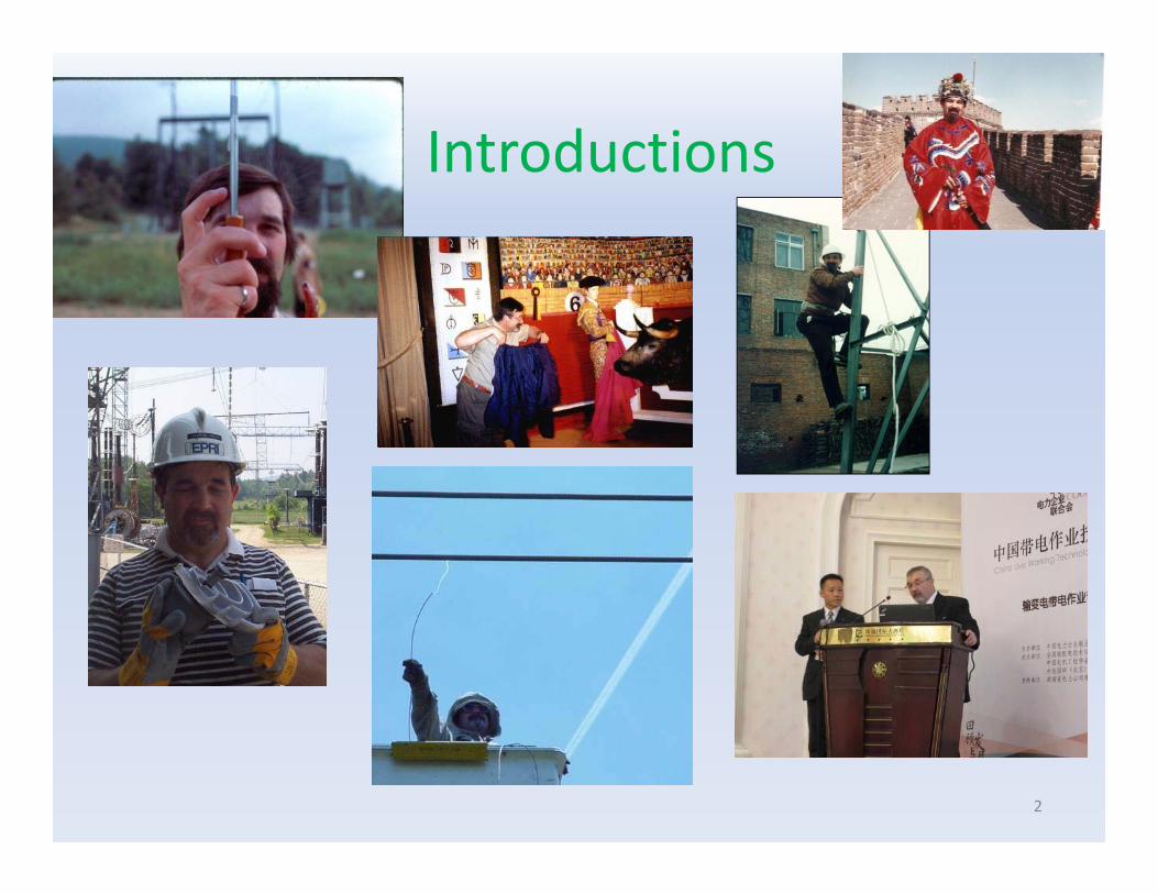
Introductions
2
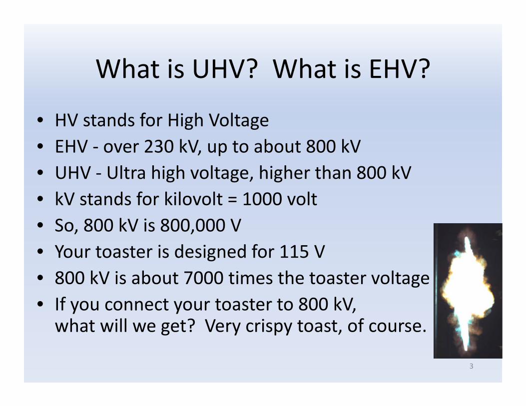
What is UHV? What is EHV?
• HV stands for High Voltage• EHV ‐ over 230 kV, up to about 800 kV• UHV ‐ Ultra high voltage, higher than 800 kV• kV stands for kilovolt = 1000 volt• So, 800 kV is 800,000 V• Your toaster is designed for 115 V• 800 kV is about 7000 times the toaster voltage• If you connect your toaster to 800 kV, what will we get? Very crispy toast, of course.
3

Why UHV?
• This has to do with power, current, losses• When we toast bread, we consume power. The power is generated far away and is transmitted by a transmission line to our house
4
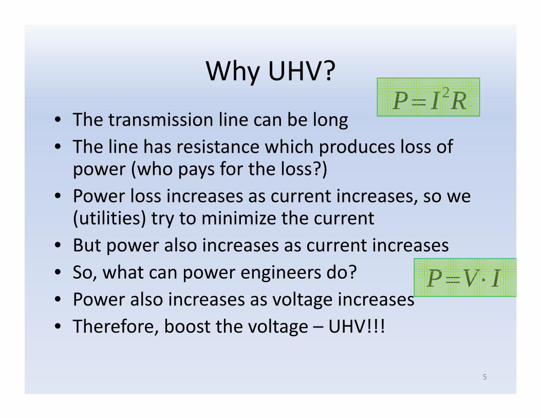
Why UHV?• The transmission line can be long• The line has resistance which produces loss of power (who pays for the loss?)
• Power loss increases as current increases, so we (utilities) try to minimize the current
• But power also increases as current increases• So, what can power engineers do?• Power also increases as voltage increases• Therefore, boost the voltage – UHV!!!
5
IVP
RIP 2

What are the highest line voltages?• Hydro‐Québec 735‐kV lines in Canada• AEP 765‐kV lines in the U.S.• 750kV and 1150kV lines (USSR‐Russia) (the 1150 kV line now operates at 500 kV)
• EDELCA (Venezuela) 765‐kV lines• FURNAS (Brazil) 750‐kV lines• NYPA (U.S.A.) 765‐kV lines (operates at 345 kV)• Eskom 765‐kV lines in South Africa• POWERGRID (India) 765kV lines• KEPCO 765‐kV lines in South Korea• TEPCO (Japan) 1000‐kV lines• 1000 kV lines in China• 1200 kV line in India
6

It all started here and in other labs• We should be proud – UHV technology was developed decades ago in Pittsfield‐Lenox, and other labs (BPA, AEP, Hydro‐Quebec, etc.)
• Pittsfield and Lenox produced several Reference Book on AC and DC
7

Recognize anyone?Recognize anyone?• 1959 ‐ today• 1959 ‐ today

History of the R&D at Lenox, andEvolution of the Redbook
History of the R&D at Lenox, andEvolution of the Redbook
1968 1975 1982 2006

Recognize anyone?
1960

The GE Transformer Plant : 1950Looks familiar?

EPRI Lenox High Voltage Laboratory – Origins
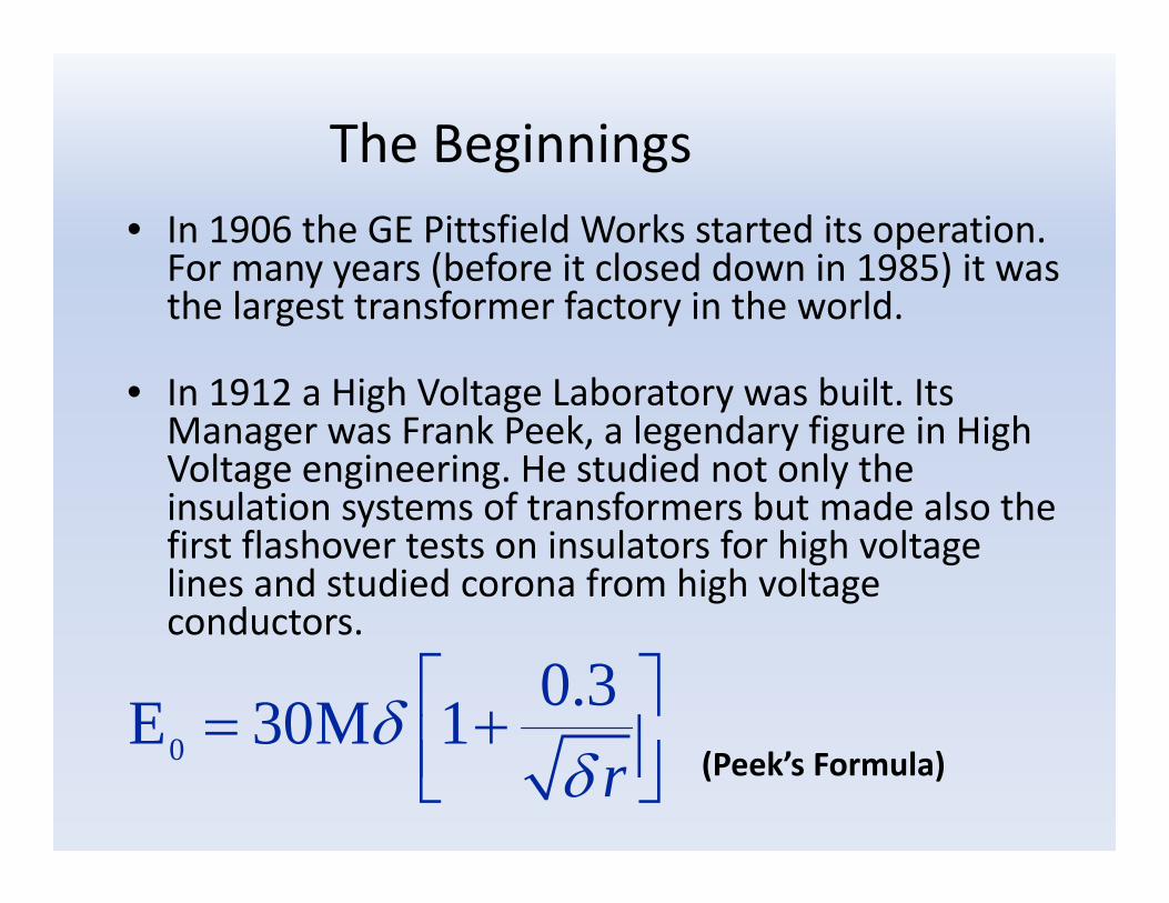
The Beginnings• In 1906 the GE Pittsfield Works started its operation. For many years (before it closed down in 1985) it was the largest transformer factory in the world.
• In 1912 a High Voltage Laboratory was built. Its Manager was Frank Peek, a legendary figure in High Voltage engineering. He studied not only the insulation systems of transformers but made also the first flashover tests on insulators for high voltage lines and studied corona from high voltage conductors.
(Peek’s Formula)0
0.3E 30M 1r

Project UHV• The rapid increase in transmission voltages appeared to herald the introduction of even higher voltages, above 1000 kV.Lionel Barthold convinced EEI that it was prudent to research these voltages. In 1967, EEI sponsored the construction of Project UHV and a five‐year research effort. GE assigned the direction of Project UHV to John Anderson.
• Project UHV, Ultra High Voltages, voltages of 1000 kV and above, is the name by which the EPRI Laboratory at Lenox was known around the world.
• Project UHV started with a single‐phase test line that could be energized up to the phase‐to‐ground voltage of a 1500 kV three‐phase line.

Laboratory Layout
Fog chamber
Impulse generator
HVDC converter
Main test line
Corona cage
866 kV transformers
Office
River

Redbook Seminar – Lenox
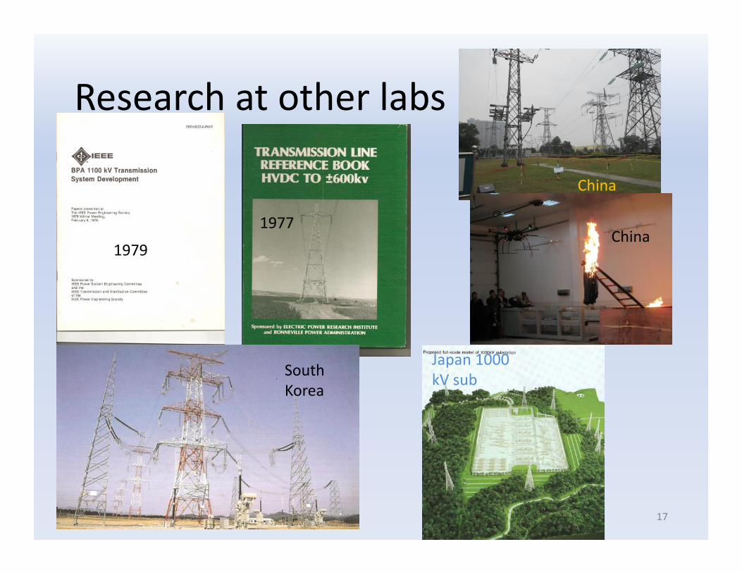
Research at other labs
17
1979
1977
China
China
South Korea
Japan 1000 kV sub

UHV lines
18

Hydro Quebec 735 kV ‐ Canada• First transmission line above 700 kV place in‐service in 1965
• Designed to move large blocks of power 300 – 600 miles– 5300 MW from James Bay
• Experienced many socio‐political forces– Energy needs not always in harmony with environmental goals
• Developed various tower designs
Figure 15.4‐1 First‐generation Hydro‐Québec self supporting 735‐kV tower.

Hydro Quebec 735 kV ‐ CanadaFigure 15.4‐3 Hydro‐Québec/TransÉnergie tubular self supporting tower.
Figure 15.4‐4 Hydro‐Québec/TransÉnergie reinforced lattice steel tower.
Figure 15.4‐2 Hydro‐Québec/TransÉnergie Chainette suspension tower.
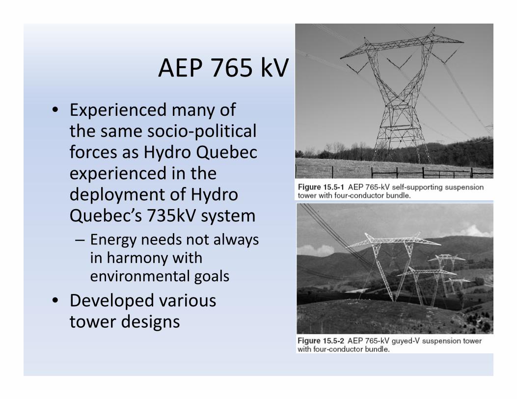
AEP 765 kV ‐ USA• Experienced many of the same socio‐political forces as Hydro Quebec experienced in the deployment of Hydro Quebec’s 735kV system– Energy needs not always in harmony with environmental goals
• Developed various tower designs

AEP 765 kV ‐ USA• AEP’s first generation 4‐cond.bundle uses with 954 kcmRail conductor
• AEP’s second generation 4‐conductor bundle uses with1351 kcm Dipper conductor
• The new 765 kV line uses 6‐conductor bundle with Tern conductor
• AEP installs 30 or 32 porcelain disc insulators in a string, depending upon conductor to tower clearances

USSR 700 kV and 1150 kV ‐ Russia• The USSR EHV system was developed to address the vast expanse of the original USSR system and generation located remotely from population centers– 4400 miles across the USSR grid
• Voltage selected by technical requirements– Land cost minimal– Environment given limited attention (compared to the West)
• First 750 kV line– 1967, 55 miles long Figure 15.6‐4 1150‐kV tower.

USSR 700 kV and 1150 kV ‐ Russia• Eventually, USSR EHV grid contained 5000 miles of 750 kV– 1900 miles in present‐day Russia
• 1150 kV test station and line established in 1973
• USSR planned for 6200 miles of 1150 kV– 1500 miles constructed– Only 550 miles ever operated at 1150 kV
• Initial 1150 kV operation in 1985. Since 1995 all 1150 kV lines have operated at 500 kV
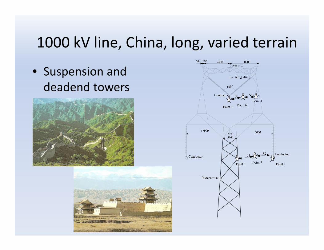
1000 kV line, China, long, varied terrain
• Suspension and deadend towers

1000 kV lines, ChinaJindongnan‐Nanyan‐Jingmen project
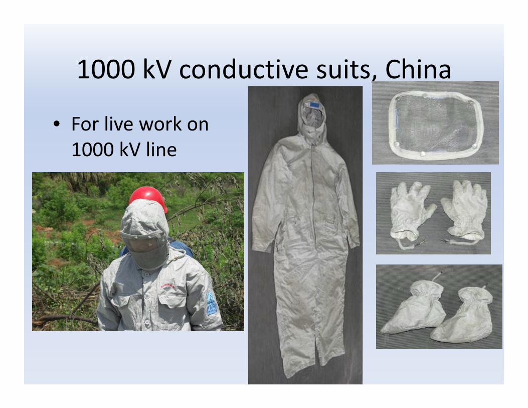
1000 kV conductive suits, China
• For live work on1000 kV line

Tokyo Electric Power Company (TEPCO) 1000‐kV Lines ‐ Japan
• Continuing growth exceeds the capacity of 500 kV system
• Difficult to obtain ROW• Decided to construct 1000 kV lines
• One line was energized in 1992 at 500 kV, still operating at 500 kV
• Another line branch has been constructed
• Once the entire system is completed, it will be energized at 1000 kV

Optional photo or graphic
1000 kV line, Japan

Optional photo or graphic
Double‐circuit vertical 765 kV line, South Korea
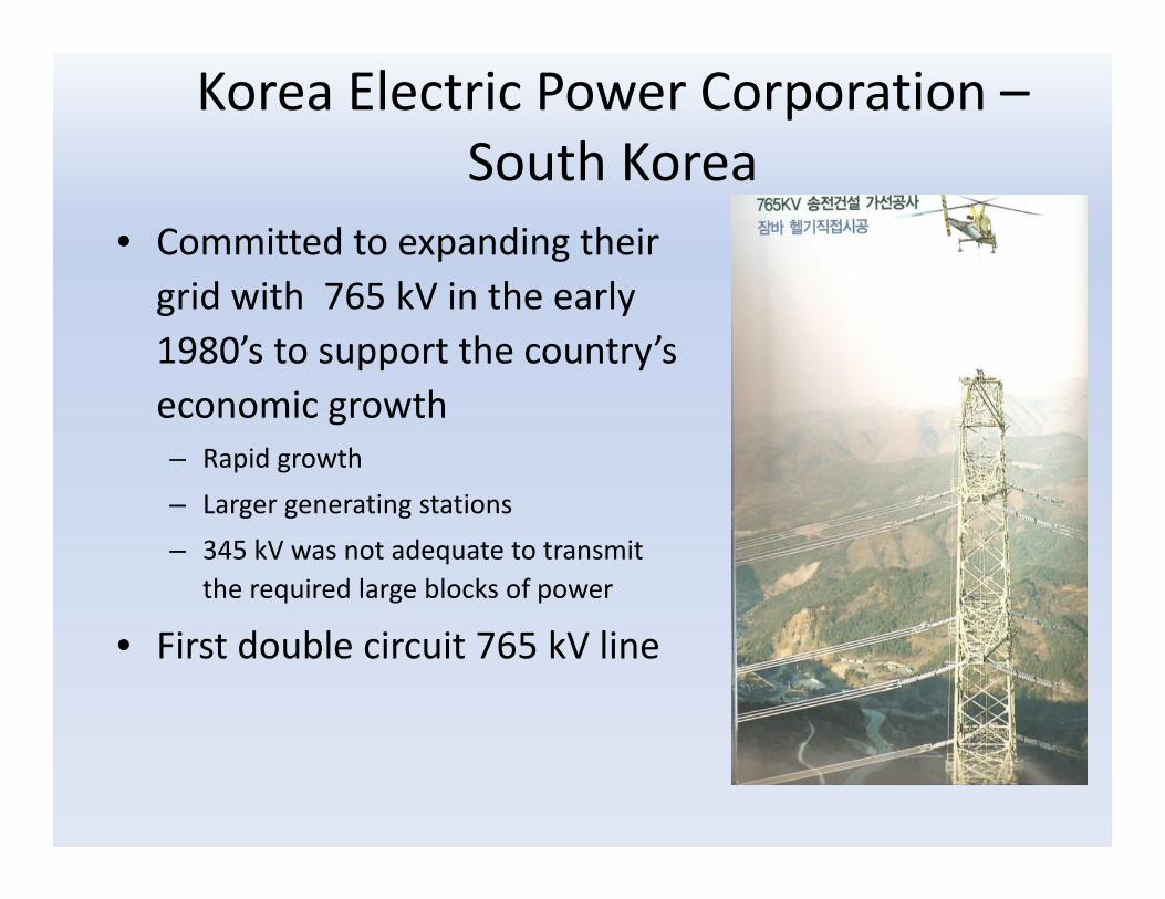
Korea Electric Power Corporation –South Korea
• Committed to expanding their grid with 765 kV in the early 1980’s to support the country’s economic growth– Rapid growth– Larger generating stations– 345 kV was not adequate to transmit
the required large blocks of power
• First double circuit 765 kV line

Korea Electric Power Corporation –South Korea
• Insulation varied with contamination levels and elevation– 28 discs in clean areas at low elevations
– 58 discs in heavy contamination areas at high elevations

Korea Electric Power Corporation –South Korea
• A 6 conductor bundle was used– LN‐Grackle conductor– Raised strands used to increase drag and limits the possibility of Aeolian noise
Figure 15.12‐5 Cross‐section view of a LN‐Grackle conductor.
Figure 15.12‐6 Six‐conductor bundle spacer damper.

Korea Electric Power Corporation –South Korea
• Tower main members are steel tubular pipes– Work staging platforms were
installed at hillside tower locations to minimize environmental impact of construction
• Typical tangent tower is 300' tall– Each tower can accommodate a
gas‐powered car as an elevator
Figure 15.12‐3 765‐kV tower showing elevator and its rail.

1200 kV, India
35

Towers support conductors
• Some towers are small, some are very massive, some are very pretty
• Made of wood, steel, concrete
36

More towers
37

Some tower carry one line, some two or more
38

Some towers and lines fail
39

Some towers and lines have problems
40

Work has to be done on tower and lines
41

Thank you!
text
42
BETC