UF JPC2006 revised - Defense Technical Information · PDF fileAmerican Institute of...
49
AFRL-PR-WP-TP-2007-219 ACHIEVING AFRL UNIVERSAL FADEC VISION WITH OPEN ARCHITECTURE ADDRESSING CAPABILITY AND OBSOLESCENCE FOR MILITARY AND COMMERCIAL APPLICATIONS (PREPRINT) Alireza R. Behbahani NOVEMBER 2006 Approved for public release; distribution unlimited. STINFO COPY This is a work of the U.S. Government and is not subject to copyright protection in the United States. PROPULSION DIRECTORATE AIR FORCE MATERIEL COMMAND AIR FORCE RESEARCH LABORATORY WRIGHT-PATTERSON AIR FORCE BASE, OH 45433-7251
Transcript of UF JPC2006 revised - Defense Technical Information · PDF fileAmerican Institute of...

AFRL-PR-WP-TP-2007-219
ACHIEVING AFRL UNIVERSAL FADEC VISION WITH OPEN ARCHITECTURE ADDRESSING CAPABILITY AND OBSOLESCENCE FOR MILITARY AND COMMERCIAL APPLICATIONS (PREPRINT) Alireza R. Behbahani NOVEMBER 2006
Approved for public release; distribution unlimited.
STINFO COPY
This is a work of the U.S. Government and is not subject to copyright protection in the United States. PROPULSION DIRECTORATE AIR FORCE MATERIEL COMMAND AIR FORCE RESEARCH LABORATORY WRIGHT-PATTERSON AIR FORCE BASE, OH 45433-7251
i
REPORT DOCUMENTATION PAGE Form Approved OMB No. 0704-0188
The public reporting burden for this collection of information is estimated to average 1 hour per response, including the time for reviewing instructions, searching existing data sources, searching existing data sources, gathering and maintaining the data needed, and completing and reviewing the collection of information. Send comments regarding this burden estimate or any other aspect of this collection of information, including suggestions for reducing this burden, to Department of Defense, Washington Headquarters Services, Directorate for Information Operations and Reports (0704-0188), 1215 Jefferson Davis Highway, Suite 1204, Arlington, VA 22202-4302. Respondents should be aware that notwithstanding any other provision of law, no person shall be subject to any penalty for failing to comply with a collection of information if it does not display a currently valid OMB control number. PLEASE DO NOT RETURN YOUR FORM TO THE ABOVE ADDRESS.
1. REPORT DATE (DD-MM-YY) 2. REPORT TYPE 3. DATES COVERED (From - To)
November 2006 Conference Paper Preprint 10/01/2005 – 08/30/2006 5a. CONTRACT NUMBER
In-house 5b. GRANT NUMBER
4. TITLE AND SUBTITLE
ACHIEVING AFRL UNIVERSAL FADEC VISION WITH OPEN ARCHITECTURE ADDRESSING CAPABILITY AND OBSOLESCENCE FOR MILITARY AND COMMERCIAL APPLICATIONS (PREPRINT 5c. PROGRAM ELEMENT NUMBER
62203F 5d. PROJECT NUMBER
3066 5e. TASK NUMBER
03
6. AUTHOR(S)
Dr. Al Behbahani and Capt. Eric A. Jordan (AFRL/PRTS) Richard Millar (Naval Air Systems Command)
5f. WORK UNIT NUMBER
TM 7. PERFORMING ORGANIZATION NAME(S) AND ADDRESS(ES) 8. PERFORMING ORGANIZATION Structures and Controls Branch (AFRL/PRTS) Turbine Engine Division Propulsion Directorate Air Force Research Laboratory Air Force Materiel Command Wright-Patterson Air Force Base, OH 45433-7251
Fuel Systems, Controls & Diagnostics Propulsion and Power Engineering Naval Air Systems Command Patuxent River, MD 20670
REPORT NUMBER
AFRL-PR-WP-TP-2007-219
9. SPONSORING/MONITORING AGENCY NAME(S) AND ADDRESS(ES) 10. SPONSORING/MONITORING AGENCY ACRONYM(S)
AFRL-PR-WP Propulsion Directorate Air Force Research Laboratory Air Force Materiel Command Wright-Patterson AFB, OH 45433-7251
11. SPONSORING/MONITORING AGENCY REPORT NUMBER(S) AFRL-PR-WP-TP-2007-219
12. DISTRIBUTION/AVAILABILITY STATEMENT Approved for public release; distribution unlimited.
13. SUPPLEMENTARY NOTES Conference paper and presentation submitted to the 2006 42nd AIAA/ASME/SAE/ASEE Joint Propulsion Conference. This is a work of the U.S. Government and is not subject to copyright protection in the United States. PAO Case Number (Paper): AFRL/WS 06-1663; Date cleared: 05 Jul 2006. This paper has color content. PAO Case Number (Slide Show Presentation): AFRL/WS 06-0574; Date cleared: 28 Feb 2006. This presentation has color content.
14. ABSTRACT The United States Air Force (USAF) has over 24,000 aircraft which include over 47,000 turbine engines. The aircraft systems are expensive and must be routinely modernized or upgraded to keep pace with threats, missions, and advancing technology. Each modern turbine engine includes controls and accessories which cost about 1/5 of the total cost of an engine. The main component of controls and accessories are the Full Authority Digital Engine Controls (FADECs). Currently, legacy FADEC systems are both unique and dedicated to their specific weapon system. Engine FADECs are built for three primary applications, military aviation, commercial aviation, and ground based power turbines. Today, each FADEC design is unique within its application class. Future goals are to establish a universal or common standard for engine controls and accessories which includes FADECs. This will significantly reduce the costs of both development and support across DOD platforms, costs which are currently extremely high.
15. SUBJECT TERMS turbine engine control, engine health management, FADEC, Universal FADEC 16. SECURITY CLASSIFICATION OF: 19a. NAME OF RESPONSIBLE PERSON (Monitor) a. REPORT Unclassified
b. ABSTRACT Unclassified
c. THIS PAGE Unclassified
17. LIMITATION OF ABSTRACT:
SAR
18. NUMBER OF PAGES
54 Dr. Al Behbahani 19b. TELEPHONE NUMBER (Include Area Code) N/A
Standard Form 298 (Rev. 8-98) Prescribed by ANSI Std. Z39-18

American Institute of Aeronautics and Astronautics
1
Achieving AFRL Universal FADEC Vision with Open Architecture Addressing Capability and Obsolescence for
Military and Commercial Applications
Alireza R. Behbahani, Ph.D.* Air Force Research Laboratory/ Wright-Patterson Air Force Base, OH 45433-7251
Abstract— The United States Air Force (USAF) has an inventory of over 24,000 aircraft with over 47,000 gas turbine engines. Aircraft systems are expensive and must be periodically modernized or upgraded to keep pace with changing threats, missions, and advancing technology. Controls and accessories comprise approximately 1/5 of the total cost of an engine. The main component of the controls system is the Full Authority Digital Engine Control (FADEC). Legacy FADEC systems are both unique and dedicated to a specific weapon system. Today, each FADEC design is unique within its application class. Developing a universal or common standard for engine controls and accessories which includes FADECs would significantly reduce development and support costs across DoD platforms. With engines representing up to 60% of the platform operating costs, modernizing them could provide significant return on investment and avoid the high cost of full system replacement. Obsolescence issues consume considerable funds and manpower and increase the risk to operational missions and the supply pipeline. To minimize the impact obsolesce, technology insertion can provide alternatives that leverage state-of-the art hardware and software to resolve the unavailability of critical parts, enhance performance and decrease cost. These alternatives will be developed through open system architectures with common or “universal” standardized inputs and outputs with improved reliability (reduce failures), common and advanced materials, reusable software, decreased number of components, high-reliability modules and improved manufacturing processes. The universal FADEC system for DoD engines will involve a family of common components. It will consist of a real-time operating system and partitioned application software (AS) structure. These components will significantly ease the strain on the supply and maintenance infrastructure. The universal FADEC vision is to develop a common input/output scheme, open hardware and software architecture, and generic circuit modules. A systems approach will be employed, considering sensors, cabling, connectors, and interface standards, as well as the FADEC electronic hardware and software.
Nomenclature AFMC = Air Force Materiel Command AFRL = Air Force Research Laboratory AS = Application Software COTS = Commercial Off-the-Shelf DoD = Department of Defense ETA = Event Tree Analysis FADEC = Full-Authority Digital Engine Control FMEA = Failure Mode and Effects Analysis FOM = Federation Object Models FTA = Fault-Tree Analysis I/O = Inputs/Outputs JSSG = Joint Service Specification Guide LRU = Line-Replaceable Unit OAC = Open Architecture Control OEM = Original Equipment Manufacturer * Senior Aerospace Engineer, Structures and Controls Branch, Propulsion Directorate (AFRL/PRTS)
American Institute of Aeronautics and Astronautics
2
OMAC = Open Modular Architecture Controls OS = Operating System OSACA = Open System Architecture for Controls within Automation system OSEC = Open System Environment Consortium PRA = Probabilistic risk assessment PSIP = Propulsion System Integrity Program QRA = Quantitative Risk Analysis UF = Universal FADEC UFC = Universal FADEC Consortium USAF = United States Air Force
I. Introduction Background
In May 2003, the Air Force Research Laboratory (AFRL) began to develop a plan to address potential control system obsolescence for gas turbine engines called the AFRL Universal FADEC (UF). The UF is an open architecture FADEC addressing capability and obsolescence for military and commercial applications. The UF platform is envisioned to be an industry-standard and a system of process and product solutions that is fully independent and composable. Composability means that the behavior of each module is unaffected by the number, order or types of modules in a cluster. This is a very powerful concept for application. This concept gives the UF the flexibility to support a broad range of applications without extensive development, analysis, and certification for each variation. Composability also means that modules can be developed by different teams at different times, or in parallel, and it is given that the modules will integrate seamlessly.
The “Open Systems” concept has been diffused into computers and controls in the nuclear, chemical, manufacturing, and civil engineering areas. The terms and definitions for open system are far less exact and uniform across industries. There is a need for new and vendor-neutral open universal control systems for aerospace engineering. Starting in 1992, a European project named Open System Architecture for Controls within Automation system (OSACA), a similar project in Japan named Open System Environment Consortium (OSEC), and a third project in the US named Open Modular Architecture Controls (OMAC) began defining open system architectures. Open controllers are used in controls engineering for merging different specifications into a unified architecture in many different industries. Open Architecture Control (OAC) is well known in the field of machine control. At the present time, however, there are no unified control systems for aircraft engines. This is the basis for this paper for a universal controller platform that is applicable across all engines.
The Obsolescence Issue of FADEC The DoD defines obsolescence as diminishing manufacturing sources and material shortages (DMSMS).
DMSMS is a serious issue for the DoD, airline community, and many commercial industries. Although increased reliability has lengthened system life cycles, decreased demand, fewer manufacturers, and rapid advances in technology have shortened component life cycles from between 10 and 20 years to between 3 and 5 years. The Deputy Under Secretary of Defense for Logistics (DUSD (L)) indicates that the average cost to redesign a circuit card to eliminate obsolete components is $250,000 6. The Electronic Industry Association (EIA) Manufacturing Operations and Technology Committee reported a cost range for redesign of between $26,000 and $2 million (ARINC 1999).Obsolescence issues consume a considerable amount of funds and manpower, increase the risk to operational missions, and increase the risk to the supply pipeline. The obsolescence problem impacts the military services, their depots and other support agencies. Obsolescence of electronic sub-components is one of the major factors driving the frequent replacement of propulsion control systems. A FADEC life cycle is around 8 years, compared to the engine life, which is greater than 20 years. FADEC obsolescence is very costly. Fleet replacement for the FADEC upgrade using a FADEC kit for an F100 series engines can cost the US government as much as $128.3 M at a $86K per unit 7. The kit configuration included tubes for oil supply, FADEC coolant supply, T3 probe, consolidated 1553 harness, a box containing all aircraft interfaces, engine identification plug, and a FADEC hardware and software for control and diagnostics. The upgrade provided compatibility for new interface and future engine diagnostics 7. These costs identify the need for aggressive obsolescence management programs. Obsolescence planning is not currently a part of the Joint Service Specification Guide (JSSG) or the Propulsion

American Institute of Aeronautics and Astronautics
3
System Integrity Program (PSIP). Clearly, there is a need to integrate hardware and software upgrades into the life cycle plan. Development and implementation of common processes and effective tools to plan for and manage obsolescence across DoD will result in considerable cost avoidances and savings.
Minimizing the Impact and Cost of Obsolescence
To minimize the impact and the cost of obsolescence, the best engineering practices among all industries should be utilized in designing the FADEC. Reuse the things that work, and simply re-enhance the same components. Integration with the OEMs must be given the first priority. Collaborating with the other industries may provide an environment for using standardized components. Ask yourself, “is this going to be useful for a long time to come?” Make obsolescence planning a part of the design engineering. If it is determined that a technology insertion resolution is potentially applicable, then a detailed design analysis and trade-off study should be done to determine if the resolution is technically sound and economically feasible and to ensure that a third party would be able to make some components. Technology insertion can develop alternatives that leverage state-of-the art technology that not only resolves the critical parts problem, but may also enhance performance and decrease cost.
Several initiatives have been proposed to minimize obsolescence issues. Open system architectures with common standardized I/O’s have been identified to be the most important initiative that will lessen the impact of obsolescence. Improving the manufacturing processes and minimizing the number of components may also offer some help to minimize the impact. This may be part of the plan for many manufacturers. Common and advanced materials, modules, parts, and software are also other initiatives that will help. Making Obsolescence planning a part of the design engineering will provide the best approach for obsolescence problems. To meet these objectives, the UF needs to be integrated during the design of the system, be distributed throughout the system, have no information bottlenecks, have no single point of failures, be adaptive, be able to correctly react to sudden degradations or failures, and be flexible enough to allow revisions that react to new opportunities. A design paradigm shift is needed to make the UF successful both in operation and in sustainment.
Proactively Addressing FADEC Issues
To proactively addressing the FADEC issue, the FADEC design process must be examined carefully. Compare the present FADEC with what it can be in the future. The software component of FADEC is expanding rapidly. There are advancements in the hardware capability as well. It is much better to, simplify, standardize, reuse, and spend resources on advancement rather than by reinventing the wheel with each new application. To improve the FADEC, one must envision the present and ideal FADEC. Table 1 is an illustration of a typical current FADEC compared to what could be realized in the future.

American Institute of Aeronautics and Astronautics
4
Table 1: Components of Current and Future FADEC Current FADEC Future (Ideal) FADEC
Not Upgradeable
Single application mindset Unexpected Shutdown
Best Practices Shorter Life Span
Not Adaptable High Cost
Non-standard I/O Non-standard Power Supply
Custom Electronics Non-distributed Custom designs
Upgradable
Multi-application Measured proaction, reaction
Essential Practices Longer Life Span
Adaptable Lower Cost
Standard I/O / Open Interface Standards Standard Power Supply
COTS Electronics Distributed-Modular Prognosis capability
Integrated with Control / Flight / Thermal /Power/ Human factors
Maximum interoperability of diverse components Ease of customization and extension
II. OPEN-ARCHITECTURE PLATFORMS FOR UF Open-system architecture enables the designer to fundamentally change the way UFs are operated and serviced.
Using commercial off-the-shelf (COTS) components allows the UF to be upgraded with ease. Until recently, open architecture of the UF in industries has been misunderstood, mostly because there is no universal definition of open architecture. Common, flexible, versatile FADECs have been used by engine manufacturers for specific applications, but they have still retained significant unique and proprietary features that have kept them from being universally applicable. Open architecture does not mean simply the sharing of information so that equipment from different manufacturers can work together. That definition still limits the number of compatible products. A true open architecture exists when industry-standard communication architecture allows hardware to be interchangeable under common communication protocols. Open architecture technologies enable integration across a system, but that ability is not sufficient for a complete solution. The flexibility to communicate with other systems is also necessary. Further, open protocols by themselves do not allow total communication. In fact, using only open or standard protocols could limit a system's ability to integrate with a variety of systems and technologies on the market today.
To be truly open, a system must be designed from the ground up, from components which are known and
understood by the integrator. This is why FADEC manufacturers need a universal specification which requires that software and hardware are compatible not only with each other but with those used by the rest of the aerospace industry. Traditional approaches to FADEC design and development suffer from the following issues:
• Current FADECs cannot cope with the frequency of updates needed for obsolescence issues. • The service, maintenance and repair cost are very high for non-standard architectures. • Trained professional experts to work on the FADECs are decreasing in numbers. • There are a large number of incompatible test cells for testing and certification of FADECs.

American Institute of Aeronautics and Astronautics
5
There is great potential for modernization of the turbine engines used in military aircraft by taking advantage of the capabilities of modern FADECs. The UF open architecture design gives everyone maximum flexibility in both software and hardware by:
• Standardizing communication interfaces and protocols are to make them compatible with the variety of other components, sensors, and flight computers.
• The open-architecture software allows integration of 3rd party peripheral devices such as operating
systems and application software via a third party open application programming interface, giving OEM the opportunity to add value by integrating their own technologies with the FADEC.
• FADEC designers can easily upgrade or interchange FADEC hardware, software, or peripheral components without having to reengineer their entire FADEC logic.
III. UNIVERSAL FADEC SYSTEM CONCEPTS Understanding the power of the UF infrastructure and leveraging that power by applying it to different platforms is the key to implementation. Visualize a singular UF platform that leverages a common physical and logical infrastructure to provide UF across the industries similar to personal computers. In this case, FADEC platform infrastructures are used for turbine engine applications using FADECs. A standard I/O scheme allows FADEC components to easily access and share communication media, data, and above all, reuse hardware components and software. Since multiple manufacturers make the devices and the FADEC software, everyone should adhere to a standard. Different platforms may have different needs, however, and different applications may have common specifications. By creating standard tools for UF that adhere to the standard; different FADEC manufacturers can use the different tools on the UF. Finally, an application level standard for the exchange of information between FADEC manufacturers exists so devices can easily communicate with the aircraft and engine health management experts. Testing and certification process will be reduced, since previously certified and tested components do not need to be recertified.
A UF is designed to accommodate the needs of a defined group of engines applicable to both military and commercial systems using the evolution of modular controls architecture and designed on a fault tolerant architecture, specifically for time-critical engine control. The UF has attributes comparable to the ideal FADEC which is a flexible, modular design which will easily accommodate new engine and vehicle-specific features while reusing common software and hardware modules from existing designs. A universal FADEC system will employ a standard hardware and software architecture. It will consist of a real time operating system and partitioned application software (AS) structure. Hardware circuit modules will be based on advanced IC packaging and be interchangeable. In the UF, control electronics size and weight will be reduced and performance and maintainability will be significantly improved. Figure 1 indicates the UF strategy including “plug and play.

American Institute of Aeronautics and Astronautics
6
Figure 1: UF Configuration and Strategy
The three elements of UF and their characteristics are as follows:
1. Controller Hardware Standard Circuit Board Definition - Interchangeable Modules - Common LRU (Box) Designs - Standard Electrical Architecture - Advanced Semiconductor Packages 2. Sensors & Interface - Standard Sensor Outputs - Specification for Level and Configuration - Wiring Harness Simplification - Robust – Interchangeable Inputs
- Enables Large Cost Reduction
3. Software - FAA Certified Auto Code - Real Time Operating System - Commercial Modeling Tools - Standard OS Kernel - Intellectual Property Enablers - Application Software (AS) - Control logic - Schedules, ratings - Analytical Engine models
In the UF configuration and strategy, there are different classes of FADEC application. Common elements are redundancy management, interchangeable circuit modules, and significant application flexibility. There are many

American Institute of Aeronautics and Astronautics
7
classes of FADECs in service today. Key discriminators are complexity and certification requirements for each type of application. Commercial aviation FADECs have the highest level of safety requirements. Correspondingly, their development and support costs are high. Military FADECs have slightly reduced certification requirements; however, their non-recurring engineering cost is high. Power generation FADECs have the lowest development and support cost because the power industry has standardized controllers to a large extent and their operating requirements are considerably less complex. The characteristics of different classes of FADECs are listed below:
Class A: Military – Sophisticated Fighter Jets Class B: Military – Low Cost Not Man-Rated Class C: Commercial – Aerospace Class D: Military – Demo Engines Class E: Commercial – Ground Based Class F: Commercial – Low Cost Class G: Auxiliary Power Generation All classes have common components, and some have additional components or architecture supports for unique
functions. The classification of FADEC shown above is somewhat arbitrary. The major class separators are cost, complexity in hardware and software, installation, vehicle communication, risk assessment, certification process, and cooling requirement.
FADEC manufacturers, OEMs, customers, independent and dependent suppliers, service companies, and trainers all benefit from this technology because it enables them to develop FADECs faster, cheaper and accelerate delivery to the OEMs and customers. By developing the FADEC specific software and hardware with a common, universal, and generic industry-standard, the FADEC manufacturers can build a library of reusable objects based on the latest software techniques and hardware standards. This approach will result in the software being developed while hardware are being designed and will significantly reduce the hardware and software integration cycles. In addition, the sensor and aircraft manufactures can take advantage of the common, universal standards to continuously reduce the cost of designing the FADEC without each time having to start the design process from scratch. Additionally, this UF concept will help technology interchange between commercial and military products. Just as significant, are the many advantages of an open architecture platform UF to the end user of engines. An open system architecture enables the end users to fundamentally change the way they operate and service their FADECs. The end users, based on their field experiences, can suggest FADEC component design changes to the OEM, without significantly requiring major changes to the overall FADEC design. The inherent reliability of any component can not change without redesign. Any component that experiences a high failure can be suggested to be re-designed without major headaches. A more detailed list below shows some possible specific benefits from UF. The list needs to be endorsed by FADEC manufacturers. It shows specific technologies that may provide some of these benefits.
Detailed advantages of UF: • Reconfigurable inputs and outputs (reusable modules). • High bandwidth internal/external serial data bus connectivity (reduced weight and increase throughput, EMI-
immune communications). • Better thermal management.
• On-board prognostics, real-time prognostics, embedded wire integrity, plus control system LRU. • Supports Model-based control.
• Improved Maintenance Management • Reduced Weight (replacing multiple controllers with ONE BOX). • Greater throughput and physical partitioning of critical and non-critical functions. • Focus on generating product content (instead of generating a framework). • Reduced OEM cost (higher re-use in multiple applications). • Design, development, risk, and qualification cycle time is significantly reduced (reduce non-recurring
engineering cost). • Standard interfaces (opportunity for collaboration). • Smaller logistics footprint.

American Institute of Aeronautics and Astronautics
8
• Reduced support costs (sharing of common modules /cards between FADEC applications). • Turn-around time will be reduced (modular exchange). • Increases field reliability.
. To achieve these benefits, the technology enablers are high speed serial communication, increased component
densities, reduced component power, high performance processing elements. The challenges along way for UF are optimize packaging volume, optimize FADEC weight, minimize recurring cost, address backward compatibility applications, obtain engine supplier input and buy-in, understand airframer roadmaps, and leverage industrial and automotive protocols.
IV. UF: WHO WILL LEAD?
Who is driving the movement toward open-architecture hardware for the UF, and how open should it be? Views on open hardware come from interested parties such as manufacturers, end-users and integrators. The industry consortium, consisting of Honeywell, Hamilton Sundstrand, and BAE Systems, strongly supports the need for development of a Universal FADEC concept. Consortium-developed standards will make up a second class of “open standards”. These may be as formally developed as “official standards” for UF. OEMs, users, and others usually produce these open specifications. Usually technology driven, it is expected the UFC will also publish "accepted" standards in formal form that are acceptable by the OEM and users. These standards will provide a basis for UF platform.
The consortium accepts that some level of openness in hardware components is inevitable. The extent to which the components are interchangeable depends on the confidence a FADEC manufacturer has in its system. Many manufacturers see a minimum level of interchangeability as an opportunity to satisfy their customer base. The reason it can be so difficult for some FADEC integrators to combine all their functions into one comprehensive system is that most systems are made from major components built by different companies. This can lead to a fragmented system that is less desirable and that operates only at the level of the lowest common denominator. It's as if integrators are taking pieces of different puzzles and trying to pound them together into one picture. The pieces just do not fit. Even if they are able to force integration, the picture may not make sense.
The UF will allow for easier integration of system components, simplified system design, and increased capabilities. Open hardware allows for greater flexibility in software design. It is not expected that every component of the UF needs to be standardized. The UF Consortium (UFC) should start with a minimum set of standards for open architecture, before a reliable UF open architecture can be adopted across all platforms.
There are already several FADEC manufacturers that use open, third-party hardware enhanced by software, packaging and a custom front end. All FADEC manufacturers use third-party components to some degree. However, there is a drive for the development of open standards. The strategy for the UF consortium is to use open, third-party hardware in conjunction with a highly customizable front end, and each FADEC manufacturer should be able to use built-in levels of security and proprietary elements in its hardware and software, including software and special components (hardware substitutions) to keep the product as their own. Hardware and software standards should provide consistency, reliability, training, and cost savings both to FADEC manufacturers and to end-users. The future of UF open systems lies in the software. Software will address the functional, graphical user interface, networking and other Model-based Control requirements.
V. The UF DESIGN CHALLENGE
The key challenge for the UF is developing a robust integrated FADEC for sustainability of a specific platform. As the demand for capability grows, the only way out is “design in” the flexibility into the FADEC from the beginning, making it applicable across all platforms with obsolescence in mind. Methodologies and tools to achieve

American Institute of Aeronautics and Astronautics
9
this are currently lacking. Universal FADEC design must be integrated with system-level design. UF transformation requires commitment and decisive leadership.
VI. UF DESIGN IMPLEMENTATION
Deploying COTS in the design should be encouraged. Process requirements drive the selection of hardware and software. The capacity of available hardware and software constrain the set of processes that can be implemented. It is necessary to determine if the constraints allow the hardware and software to fit within the system without a great deal of re-engineering. An evolutionary development cycle may be required to balance desired UF features with the capabilities of current technologies (see Figure 2).
Figure 3 shows how to design functional models for UF. The design process for FADEC should start with advanced studies and end with operation. Initially, capability and performance requirements should be clearly defined. Examples of expected performance are ease of technology insertion, growing capability, improved interoperability, less integration risks, lower cycle time, vendor independence, reduced total ownership costs, in addition to technical requirements. Maintenance and service availability for the entire FADEC system and their costs, training costs should be considered in the design phase. Multiple manufacturers' initial and future system integration responsibilities should also be reviewed. Developmental program risk management should have a strong orientation to acquisition strategy, design, and project control. Identify risk drivers for FADEC design early by influencing the acquisition plan, organizational structure, technology development approach, organization structure staffing plan, etc. Quantitative Risk Assessment (QRA) should be an integral part of the design process and becomes essential to operations and sustainment. There is a potential for ambiguity and for conflicts among independently made decisions such as OEM, subcontractors, and FADEC manufacturers. These ambiguities may lead to inconsistency, non-standard hardware or software. Alternative concepts, migration between platforms, acquisition, technology, and support strategies should be explored. Initial FADEC architecture should be developed by partitioning the candidate components into functional and logical modules. Modules with rapidly changing technologies versus those with potential interoperability impacts, and those with absolute propriety technology should be identified. Many functions that can be performed with the software should be considered first before considering hardware. Documentation issues, software licenses, third party maintenance availability, and capabilities are some of the issues that come with the UF platform. Feasibility of making the key interfaces, sensors, or even modules through “open standard sources” from third parties should be seriously considered. This will minimize the impact of obsolescence. Conformance and interoperability testing issues and methods ("plug and play") should be considered.
Processes Software
ConfiguresConfigures
ConstrainsConstrains
Documented Hardware
Figure 2: Achieving UF Design

American Institute of Aeronautics and Astronautics
10
Pro-active obsolescence planning is needed for the future systems. From the design phase, to analysis, to management, emphasis should be made on obsolescence and upgradeability, as well as on cost control and capability enhancement. Using parts and components that are universal and, above all, using the lesson learned and the best engineering practices available is the best approach. In the pro-active obsolescence planning, three tasks are identified: Task I (design information), emphasizes the need to understand the system and performance requirements, evaluate architectural options, and perform trade studies that drive electronic part selections for the UF. Then, the obsolescence planning is performed. In Task II (design analysis), the proper analyses to support architecture design is performed. Task III (engine life management) addresses obsolescence issues on fielded FADECs. The roles and responsibilities of the UFC Team members are sharing interface types and size requirements of existing products, sharing technical expertise and experience with existing UF products, and providing end user, airframer and engine supplier points of contact. The short-term goals and objectives are the following: defining UF objectives, identifying target markets, developing the UF roadmap, and identifying and surveying end users and airframers. Figure 4 indicates the UF must have an integrated approach. This approach, integrates and collaborates the OEMs, customers, manufacturers, and considers all stakeholders to synergize to keep the software and hardware in harmony to benefit everyone.
Figure 3: Current and Future FADEC Design Process
American Institute of Aeronautics and Astronautics
11
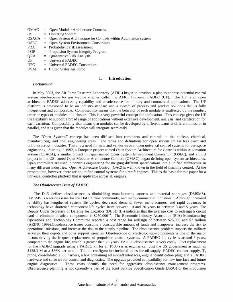
Figure 4: UF Integration
It is expected that the UFC will engage engine manufacturers in UF projects. This includes definition of UF
features and capabilities, establishment of UF interfaces, establishment of volume and weight goals, and identification and establishment of mitigation plans for UF risks. Help from all participants is needed to succeed with the UF. Trade studies on UF should be given the first priority. This is a win-win for everybody. Modernization will provide a significant return on investment, if the UF is adopted. Funding and execution of rapid-response demonstration programs to build a broad controls and accessories experience base, including software, should be encouraged to reduce cost and to maintain technological superiority. Lastly, as a footnote to this paper, it is important to remember that it is easy to get consumed with the business end of the Universal FADEC and the technical challenges that are required to achieve the open system architecture. Use of commercial design standards and participation in standards setting bodies is crucial.
VII. THE FADEC DESIGN PARADIGM: Integration should be performed at the very early functional design. Assess Federation Object Models (FOMs) by means of optimization. All stakeholders must be informed of the objectives. This includes OEM, end users, and the subcontractors. In changing the current design process, it is essential that the following are followed: Proposed Design Paradigm Shift #1: Employ methodologies to integrate the UF in the very early functional design stage by means of functional models and function-based failure and risk assessment. Proposed Design Paradigm Shift #2: Employ methodologies to assess impact of FADEC FOMs on the system level FOMs by means of multi-objective multi-level optimization, including all stakeholders in the mission lifecycle (design, maintenance, operations).
Hardware and software standards should provide consistency, reliability, training and cost savings to FADEC manufacturers and end-users. Figure 5 shows the FADEC Design strategy. It shows how UF architecture, mission, vision, strategy, and management is incorporated in every stage of the engineering process Note that the UF architecture needs to be agreed to after the initial vision, mission, and the roadmap development.

American Institute of Aeronautics and Astronautics
12
Figure 5: UF Design Strategy
VIII. Summary and Conclusion The success of the Universal FADEC and the change from proprietary FADEC to UF is based on the flexibility to select the best components in a changing environment. Users, designers, and maintenance personnel will have to become familiar with the new UF technology, just as they did with personal computers. UF systems are not a panacea but one possible solution to specific platform needs. The best solution for each particular platform will be determined in most cases by the OEM, contractors, and user's requirements. In certain applications, FADEC changes or expansion will not be beneficial, and, UF components may not be used. UF manufacturers as well as everyone involved may be better served by selecting a traditional proprietary FADEC system and carefully considering the issues discussed above in the design, specification, and construction of the project. If UF is chosen, it must be designed, specified, and procured with great care to achieve the desired results. UF success depends on active participation of the aerospace industries and government. Use of commercial design standards and participation in standards-setting bodies should be encouraged. There should be the flexibility to determine that products or services are commercial items, and demonstration programs for the challenge of pricing commercial items. Profit policies that discourage commercial outsourcing should be discouraged for the UF to succeed. Controls and accessories components that are common across different platforms must be incentivized and standardized. Policies, incentives and guidelines for using common or advanced components in controls and software, including sensors must be vigorously implemented. Life-cycle cost should be controlled from the beginning, however, only performance specifications should be used in making the final decision. Spiral upgrades, life cycle support, and the modular open systems approach should be used. Long-standing barriers and disincentives must be removed to take full advantage of the Universal FADEC technology and to be transitioned to the USAF. Finally, it should be mentioned that at the present time, due to the lack of "plug and play" interoperability, the FADEC can easily become the ultimate "stuckee"--the responsible party for all problems that cannot be readily identified--since a single point of responsibility will not exist in most cases. Even if the FADEC is installed and commissioned by a single vendor, competitive procurement of later UF changes or expansions is likely to create a divided responsibility situation. However, the UF will pave the way to solve common problems related to the FADEC, which will improve it’s obsolesce and interoperability.

American Institute of Aeronautics and Astronautics
13
References [1] Logan, Glen T., “Open Systems Joint Task Force/OUSD (AT&L)”, Executive Program Managers Course “Open Systems”, Presentation, 4 February 2004, http://www.opengroup.org/rtforum/oa_rtes/uploads/40/4623/Logan_MOSA_4_Feb_04.pdf. [2] IEEE/NEMI (National Electronics Manufacturing Initiative, Inc.), “Low Cost Open Architecture Controller Specification”, http://standards.ieee.org/catalog/nemi/index.html. [3] Anderson, R.L., Garner, T.D., Reagin, J.M., Sweeney, T.E. (November 20-21, 1996). “Open Architecture Control Systems And Standards”, SPIE (Society of Photo-Optical Instrumentation Engineers) Proceedings, Volume 2912. [4] Phillip J. Fiedler,. and Chris J. Schilb, “Open Architecture Robot Controllers and Workcell Integration”, http://www.roboticsonline.com/public/articles/Open_Architecture_Genesis.PDF. [5] “Open System Architecture for Controls within Automation (OSACA) Systems”, EP 6379 & EP 9115 OSACA I & II Final Report, Date: April 30, 1996, Document: OS2FIN4.DOC ESPRIT III. http://www.osaca.org/_pdf/os2fin4.pdf [6] Jack McDermott, Jennifer Shearer, and Walter Tomczykowski, “ Final Report Resolution Cost Factors for Diminishing Manufacturing Sources and Material Shortages”, Defense Microelectronics Activity (DMEA) McClellan AFB, CA, ARINC Incorporated, Contract GS-35F-4825G, Task Order DMEA90-98-F-0018, February 1999, http://www.dmea.osd.mil/docs/resolution_cost_factors.pdf. [7] “Control System Obsolescence, Group VI DEEC Field Kit Modification, Component Improvement program (CIP)”, Engine Advisory Group (EAG) Executive Session, ASC / Oklahoma City presentation from US Air Force, Presentation.

Achieving AFRL Universal FADEC Vision with Open Architecture Addressing
Capability and Obsolescence for Military and Commercial Applications
Briefing for 42nd AIAA/ASME/SAE/ASEEJoint Propulsion Conference
9-12 July 2006Sacramento Convention Center
Sacramento, California
Dr. Al BehbahaniControls & Engine Health ManagementStructures & Controls Branch / Turbine Engine DivisionAir Force Research Laboratory / USAF
Approved for public release, distribution unlimited
14

Universal FADEC VisionHistorical Background on FADEC Needs / IssuesFADEC Drivers Obsolescence Problem / Root Causes DoD Mandates Major thrusts towards Universal FADECStrategies for Desired CapabilitiesProposed SolutionsUniversal FADEC and Related TechnologiesIssues / ConcernSummary and RecommendationsTakeaways
OUTLINE
15

UNIVERSAL FADEC (UF) VISION:Open Architecture Addressing Capability and Obsolescence
for Military and Commercial Applications
Present: Controls & Accessories are become more advanced
Future: Integration of advanced Active controls, EHM, and Vehicle; improving The FADEC, sensors, actuators, algorithms, and EHM
Benefit: in-flight mission preplanning, and increased reliability, reduce ownership costs, increase availability, and reduce the number of required spares.Systems Engineering Process crucial to assimilate disparate data typesSystem data availability plays key enabler in defining prognostic horizonOpen Systems approach required to maximize architectural benefitsEasier said than done on Legacy Fleet
Integrating Controls and Health Management is the Key Vision
16

AFRL UF
Universal FADEC (UF) is applicable to all military and commercial applications requiring lightweight, high speed, flexible, rugged, miniature, electronic controls. Has both common Software and Hardware.
Standard Configuration – “Plug & Play” – One Unit Reconfigurable for many Thrust Class Engines, standard specifications between OEMs.
Control Electronics Size and Weight Will be Reduced – Performance and Maintainability will be Significantly Improved.
17

1990s Controls issuesThe issue was advancement in micro-processorsSensors / Actuators / software development
TodayThe issues are fast response, technological superiority, real-time operating system with on-board diagnostics / prognostics , and smart components
GoalsImprove AffordabilityReduce Sustainment CostsIncrease ReliabilityImprove PerformanceProactive Health ManagementReal-time Life TrackingIntegration
The key factors in advancing C&A and reducing the impact of Obsolescence are to open channels of communications between OEMs and access commercial technologies, that are “up and running”, and make transition time shorter.
HISTORICAL BACKGROUND ON FADECNeeds / Issues
18

FADEC DRIVERS
Obsolescence Aging
Maintenance / Replacement CostS/W & H/W
CompatibilityArchitectures
AvailabilityTechnology Updates
Technology Push / PullCapability upgradeability
Capability GrowthAffordabilityReliability / Availability / Mission SuccessFeaturesPrognostic Capability
19

WHAT IS OBSOLESCENCE?
The DoD defines obsolescence as diminishing manufacturing sources and material shortages (DMSMS).DMSMS is a serious issue for the DoD, airline community, and many commercial industries.
Although increased reliability has lengthened system life cycles, decreased demand, fewer manufacturers, and rapid advances in technology have shortened component life cycles from between 10 and 20 years to between 3 and 5 years.The Deputy Under Secretary of Defense for Logistics (DUSD (L)) indicates that the average cost to redesign a circuit card to eliminate obsolete components is $250,000. The Electronic Industry Association (EIA) Manufacturing Operations and Technology Committee reported a cost range for redesign of between $26,000 and $2 million (ARINC 1999).
Obsolescence is a problem for Everyone!
20
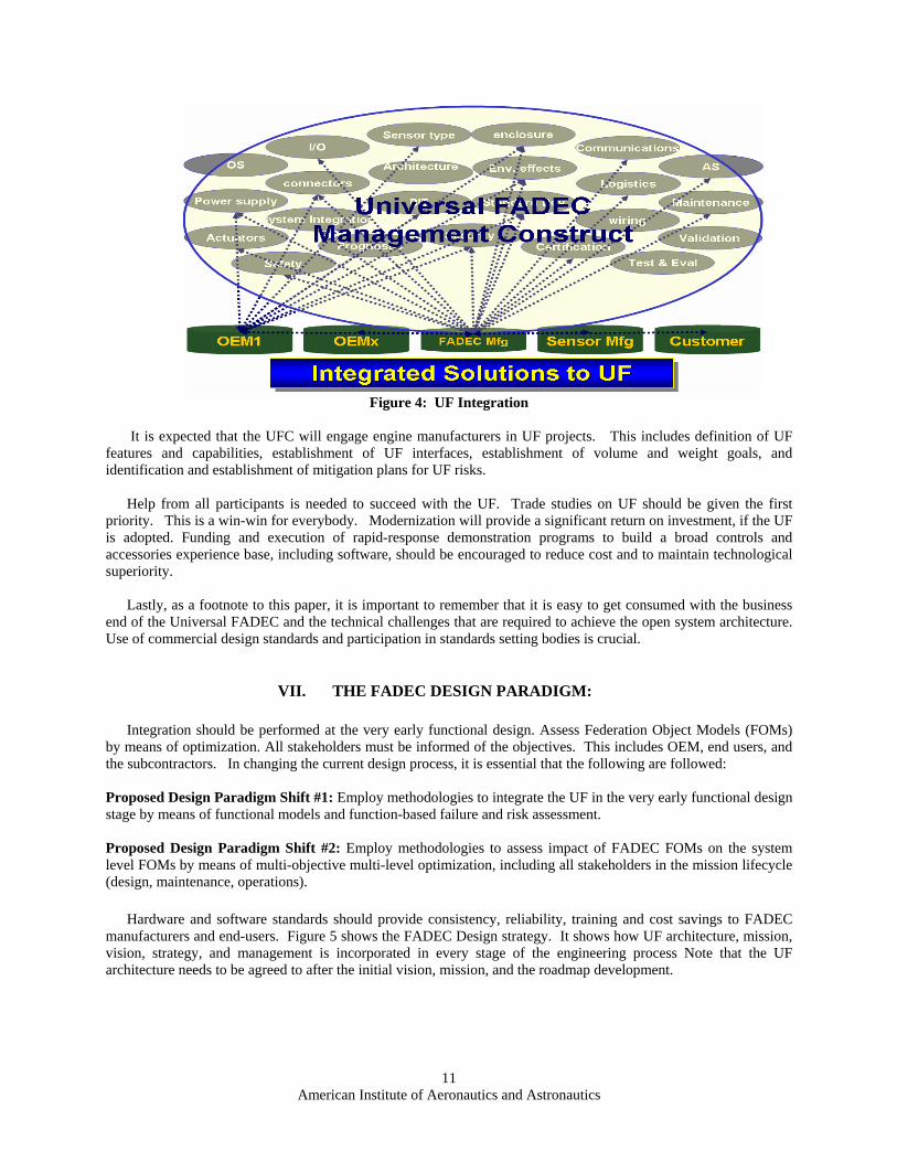
THE OBSOLESCENCE PROBLEMObsolescence issues consume considerable funds and manpower, increase the risk to operational missions and our pipeline of supply. The problem impacts the Services, their Depots and other agenciesObsolescence of electronic parts is one factor driving the frequent upgrades made to propulsion control systems replacement.
FADEC life cycle is around 8 years (Engine is > 20Yrs)5 Yr, $20-$30 M Development Program
• Design & Hardware Fabrication• Software Development• Test Program• Support Equipment Design & Test
$130 M Total Replacement Kit CostElectronic parts obsolescence is very costlyNeed to avoid design “refreshing”Need aggressive obsolescence management programsCannot afford to waste precious Continuous Improvement Program (CIP) $ on obsolescence issuesPoor obsolescence planning and management are huge detriments in meeting these requirements Obsolescence is currently not a part of the JSSG (Joint Service Specification Guide) or the PSIP
21

ELECTRONIC PARTS OBSOLESCENCEA Large and Growing Problem…
Major Cost Driver for Fielded SystemsInventory CostsRedesign Costs
Primary CausesCommercial Product Life CycleShrinking Market PresenceSmall Quantity Requirements
Contributing FactorsExtended Service Life of SystemsLong Development Lead Times
Software IssuesComputer Language Evolution Commercial Product Life Cycle
Redesign CostsOperating Systems Standards and emerging requirements
22
ROOT CAUSES FOR COST GROWTHon FADEC obsolescence
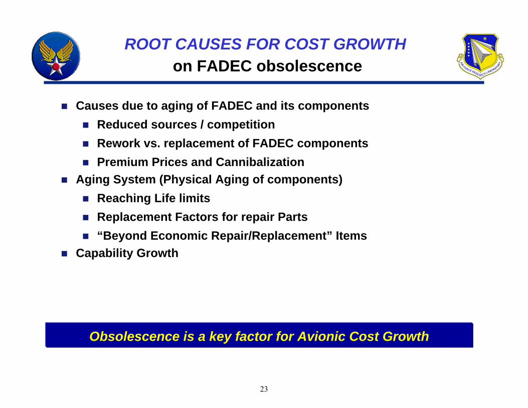
Causes due to aging of FADEC and its componentsReduced sources / competitionRework vs. replacement of FADEC componentsPremium Prices and Cannibalization
Aging System (Physical Aging of components)Reaching Life limitsReplacement Factors for repair Parts“Beyond Economic Repair/Replacement” Items
Capability Growth
Obsolescence is a key factor for Avionic Cost Growth
23

MILITARY PURCHASE NEEDS / ISSUES
Military Purchases of Total Semiconductor Industry OutputServing the Military’s Needs Involves Low Production Volumes with Stringent Manufacturing Requirements
0
5
10
15
20
25
30
35
1975 1984 Today
Ref: Hamilton & Chin, “Aging Military Electronics: What Can the Pentagon Do?”, National Defense Magazine, Mar 2001
Military Purchases no longer dictates the market!
24

DOD MANDATES
Diminishing Manufacturing Sources and Material Shortages (DMSMS)is the loss or impending loss of manufacturers of items or suppliers of items or raw materials. The military loses a manufacturer when that manufacturer discontinues or plans to discontinue production of needed components or raw materials. Source: DoD 4140.1-R Section 3.6, May 2003
Identification and implementation of common processes and effective tools across AFMC and DoD will result in cost avoidance and costsavings
GOVERNMENT OPEN SYSTEM MANDATES DoD MANDATESDoD MANDATES
DoD Instruction 5000.2, Operation of the Defense Acquisition SysDoD Instruction 5000.2, Operation of the Defense Acquisition SystemtemDoD Directive 4630.5, Interoperability and SupportabilityDoD Directive 4630.5, Interoperability and Supportability
DoD/AFMC DMSMS ProgramDoD/AFMC DMSMS Program
25

MINIMIZING THE IMPACT AND COST OF OBSOLESCENCE
Technology insertion can develop alternatives that leverage state-of-the art technology that not only resolves the critical part problem, but may also enhance performance and decrease cost. These alternatives will be developed through:
Open system architectures / Common standardized I/O’sImprove reliability (reduce Failures)Common and advanced materials / reusable softwareDecreased number of components among many programsHigh-reliability modulesImproved manufacturing processesMaking Obsolescence planning a part of the design engineering
If it is determined that a technology insertion resolution is potentially applicable, then should conduct a detailed design analysis and trade-off study to determine if the resolution is technically sound and economically feasible, and make sure the 3rd party would be able to make some components.
26
UF REQUIREMENTS
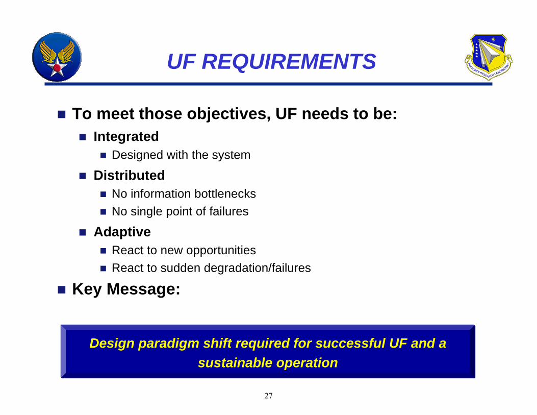
To meet those objectives, UF needs to be:Integrated
Designed with the system
DistributedNo information bottlenecksNo single point of failures
AdaptiveReact to new opportunitiesReact to sudden degradation/failures
Key Message:
Design paradigm shift required for successful UF and a sustainable operation
27

PROACTIVELY ADDRESSING FADEC ISSUESTech Push to Tech Pull
Current FADECNot UpgradeableSingle application mindsetUnexpected ShutdownBest PracticesShorter Life Span Not AdaptableHigh CostNon-standard I/ONon-standard PSCustom ElectronicsNon-distributedCustom designs
Future (Ideal) FADECUpgradableMultiapplication Measured proaction, reactionEssential PracticesLonger Life SpanAdaptableLower CostStandard I/OStandard PSCOTS ElectronicsDistributed-ModularAbility to improvement
Prognosis capabilityIntegrated with Control / Flight / Thermal /Power/ Human factorsAddressing all FADEC
issues/concerns/drivers…
28

CURRENT AND FUTURE TECHNOLOGYDEVELOPMENTS FOR UF
Reconfigurable Inputs / OutputsWiring / Signal Harness PrognosticsControl/PHM/Vehicle Integrated ArchitecturesOptical Serial CommunicationsAdvanced Cooling / Chip PackagingOn-Line Software UpgradesHigh Temp ElectronicsNetwork ComputingIntellectual Property (IP) Modules – 3rd PartyAdvanced Integrated Circuit Packages Adaptive Control Capability
COTS Electronic ComponentsReal-Time Operating System – Partitioned DesignOpen Architecture –Hardware Design Common I/O and Standard Engine InterfaceUpgradeable Hardware/Software ArchitectureFault Tolerant Hardware ArchitectureIndependent Module Processors support Reconfigurability
29

THE UF DESIGN CHALLENGE
Key Challenge: Robust Integrated FADEC for Sustainability of a specific platform
Current Limitation: FADEC is typically retrofitted as an after-thought! As the demand for capability grows
Our only way out:
“DESIGN IN” THE FADEC FLEXIBILITY FROM THE BEGINNINGacross all platforms with the Obsolescence in mind!
We currently lack methodologies and tools to achieve this!Some successful attempts:
Specify Universal FADEC “shall” statements at the beginning of project
Integrate Universal FADEC design with system-level design
UF Transformation requires commitment and decisive leadership
30

Processes Software
Configures
Constrains
Documented
UF DESIGN PROCESS:Deploying COTS as much as possible …
Hardware
COTS ISIS King… Define and Refine the Process and Configuration
Evolutionary Development Process…
31

THE SOLUTION-FUTURE SYSTEMSPro-Active Obsolescence Planning is needed
TASK I (DESIGN INFORMATION)Emphasize the Need to Understand System and Performance Requirements Evaluate architectural optionsTrade studies that drive electronic part selectionsObsolescence planning
TASK II (DESIGN ANALYSIS)Proper analyses to support architecture design
TASK III (ENGINE LIFE MANAGEMENT)Addressing obsolescence issues on fielded hardware
Pro-Active Approach to Obsolescence!
32

THE SOLUTION FOR OBSOLESCENCE
Develop Propulsion Electronics Obsolescence Management Plan under DMSMS Guidance
Future SystemsEmphasize the need to understand system and performance requirements Evaluate architectural optionsTrade studies that drive electronic part selectionsObsolescence planning
Pipeline SystemsObsolescence Management Plan
Options AnalysisOptions AnalysisProactive Obsolescence PlanProactive Obsolescence Plan
Legacy SystemsObsolescence Management Plan
TriTri--Service Active Parts InventoryService Active Parts InventoryAlternative SolutionsAlternative Solutions
Incorporate into JSSG & PSIP Document
Develop Obsolescence Management Plan
33

THE FADEC DESIGN PARADIGM: Changing the Way FADEC Design is Done
Proposed Design Paradigm Shift #1: Methodologies to integrate UF in the very early functional design stage by means of functional models and function-based failure and risk assessment
Proposed Design Paradigm Shift #2: Methodologies to assess impact of FADEC Federation Object Models (FOM) on the system level FOMs by means of multi objective multi level optimization, including all stakeholders in the mission lifecycle (design, maintenance, operations)
Current Design Process Must be Changed!34

THE WAY AHEAD … FADEC
OEM1 OEMx FADEC Mfg Sensor Mfg Customer
Sensor type enclosure
OS AS
CommunicationsI/O
Architecture Env. effects
Power supply Maintenance
Logisticsconnectors
BIT Standard Dev
Actuators Validation
wiringSystem Integration
PrognosticSecurity
CertificationTest & EvalSafety
Universal FADEC Management Construct
Integrated SolutionsIntegrated SolutionsIntegrated Solutions
But how?
35

UF GOVERNANCE PROCESSES / STRATEGY
UF Mission, Vision, Strategy
UF ArchitectureFADEC Architecture Alignment
Processes Systems Data Applications Technology
FADEC Technology Portfolio ManagementSelect Control Evaluate
System Development / Acquisition ManagementReq’ts Design Build Test Train Implement Maintain Evaluate
36

MITIGATING THE RISK OF FADEC OBSOLESCENCE
Technology insertion can develop alternatives that leverage state-of-the art technology that not only resolves the critical part problem, but may also enhance performance and decrease cost. These alternatives will be developed through:
Open system architectures / Common standardized I/O’sImprove reliability (reduce Failures)Common and advanced materials / reusable softwareDecreased number of components among many programsHigh-reliability modulesImproved manufacturing processesMaking Obsolescence planning a part of the design engineering
If it is determined that a technology insertion resolution is potentially applicable, then should conduct a detailed design analysis and trade-off study to determine if the resolution is technically sound and economically feasible, and make sure the 3rd party would be able to make some components.
Minimizing the impact and cost of Obsolescence
37

UF CONFIGURATION / STRATEGYDifferent Classes of UF…
Standard Configuration – “Plug & Play” – One Unit Reconfigurable for many Thrust Class Engines
“One size fits all” inadvertently smothers some!
Std RT OS Kernel
- High Levels of Redundancy- Dispatch With Failures - High Levels of System Integration- Configuration Flexibility
IN OUT
P4P6
P3P2
Common I/OStandard Housings
(for different classes)
Common SensorsAnd Connectors
Common Modules
Common Power Supplies
Reusable AS Modules
38

UNIVERSAL FADEC SYSTEM
Sensors & InterfaceStandard Sensor Outputs
- Spec for Level and Configuration - Wiring Harness Simplification- Robust – Interchangeable Inputs- Enables Large Cost Reduction
Controller HardwareStandard Circuit Board Definition
- Interchangeable Modules- Common LRU (Box) Designs- Standard Electrical Architecture- Advanced Semiconductor Packages
Software- FAA Certified Auto Code - Real Time Operating System- Commercial Modeling Tools- Standard OS Kernel - Intellectual Property Enablers- Application Software (AS)- Control logic- Schedules, ratings- Engine modelsFADEC Advanced Circuit Card
Control Electronics Size and Weight Will be Reduced – Performance and Maintainability will be Significantly Improved
Open S/W Architecture Provides Modularity & Reduced Integration Costs39

UF OBSTACLES
A problem with many faces – Business, Policy, and Geographic
Obstacle #1. Business RealitiesNot all FADECs have the same needs or introduce the same riskFear of shift/loss of business
Obstacle #2. Proprietary Information Assurance RealitiesShould “one size fit all?”
Obstacle #3. Geographic RealitiesThe industry is geographically dispersed Collaboration between rival companies is a no no!!Needs an Articles of Collaboration
Obstacle #4. Cost of being “Universal”High initial cost vs. long term benefits
Obstacle #5. Agreement on StandardsMy way or the highway!
40

Incentivize and standardized Controls and accessories components across different platforms
Vigorously implement policy, incentives and guidelines for using common / advanced components in controls and S/W, including sensorsControl the life-cycle cost from the beginning Use only performance specificationsSpiral upgrades and life cycle supportUse Modular open Systems Approach
Long standing barriers and disincentives must be removed to take full advantage of the Universal FADEC technology to be transition into AF capabilities
RECOMMENDATIONS
41

TAKEAWAY…
Enable changeFund and execute rapid-response demonstration programs to build a broad C&A experience base Create mechanisms to increase awareness of future commercial technology and capabilities to transfer into propulsionInvest in R&D to increase the mutual compatibility of military operating environments and commercially produced components.Experiments and rapid response demos in C&A should be encouragedUsing commercial controls parts and subsystems including S/W should be encouraged to reduce cost and maintain Technological superiorityUse of commercial design standards and participation in standards setting bodies.
UF requires commitment and decisive leadership
UF requires commitment and decisive leadership
42

1917
Developing practical engine control and health management technologies
THANK YOU!
43

Backups
44

AFRL UNIVERSAL FADEC (UF)
o Standard I/O, re-scalable, re-usable moduleso Standard Sensor Outputso High Levels of Redundancyo Dispatch With Failures o High Levels of System Integrationo Configuration Flexibilityo Standard OS Kernel o Interchangeable Moduleso Standard Electrical Architectureo Robust Interchangeable Inputso Integrated FADEC / PHM
Universal FADEC (UF) is applicable to all military and commercial applications requiring lightweight, high speed, flexible, rugged, miniature, electronic controls. Has both common Software and Hardware.
Standard Configuration – “Plug & Play” – One Unit Reconfigurable for many Thrust Class Engines, standard specifications between OEMs.
Control Electronics Size and Weight Will be Reduced – Performance and Maintainability will be Significantly Improved.
First steps: common definitions, taxonomy, I/Os and …
45

Goa
lsO
bjec
tives
Tech
nica
lC
halle
nges
Appr
oach
es
GOTCHA CHARTDigital Control Systems
Minimize the Impact of Obsolescence
Plan for Obsolescence(Factor %)
Improve Existing Part Longevity
(Factor %)
Extend Component Manufacturing Life
Change architecture so that new parts are easier to incorporate
Reduce Product Support / Maintenance Cost
(Factor %)
Change software so that it can accommodate new parts
Use upgradeable components Standardize parts of the digital
control system. Standardization allows much easier incorporation of new parts.
Standardize software, allowing for upgradeability and expansion.
Design to accommodate commercialized parts. They are much more cost effective. They are cheaper and mass-produced, in turn, easier accessibility.
Create a generic model of the digital control systems, with the ability for expansion and upgradeability.
Implement self sensing parts, taking away maintenance costs, extending life of the parts, and reducing FADEC load
Make existing parts more durable
Implementation of Life Extending Control
Reduce Production / DevelopmentCost (Factor %)
Plan for New Component Replacement
Minimize No. of Components
Use components with Standardized I/O’s (ease of Upgradeability
Continually evaluate Components for obsolescence
Incorporate Model-Based Controls
Design for “Open System”Architecture for Component
Develop Probabilistic Life code for Electronic Components
46

• Don’t lose focus on the basics – enable people
• Exploiting new collaborative ways of designing FADEC
• Adapt rapidly advancing enabling technologies
• Linking / Sharing technical activities across industries
• Integrated Flight Control, ISHM & Human Effect with FADEC
• Training – Tools – Mindset• Collaboration – Team work
UF IS NOT UNIVERSAL IF…
You’re Not Progressing Beyond Framing and Reorganizing
1
UF Transformation: A Geography Major’s Definition
Enacting fundamental change . . .
-- Structure
-- Process
-- Technology
-- Collaboration
. . . to achieve quantum capability improvements
Enacting fundamental change . . .
-- Structure
-- Process
-- Technology
-- Collaboration
. . . to achieve quantum capability improvementsThinking and Acting In New Ways…Thinking and Acting In New Ways…
Towards UF Imperatives:
What Comes Next?
What?How?
What New Ways?
47