UCR ME SOP Manual Milling Machines v5
12
1 | Page UC RIVERSIDE – MECHANICAL ENGINEERING DEPARTMENT – MACHINE SHOP STANDARD OPERATING PROCEDURES for MANUAL MILLING MACHINES REVISION: V5 DATE: 11-15-2011 TABLE OF CONTENTS SECTION TOPIC(S) PAGE Basic Capabilities 2 Basic Machine Parts 3 Safety Rules 4 1 Tramming the Head 5 2 Squaring the Vice 5 3 Setting Spindle Speed and HI/LO Gearing 5 4 Using an Edge Finder 5 5 Using Digital Read Outs – DROs 6 6 Cutting Fluids 6 7 Cutting Tool Holders 7 8 Removing and Installing Cutting Tools 7 9 Cleaning the Machine 8 10 Unfinished Work 8 11 Climb vs. Conventional Milling 8 12 Drilling and Drill Chucks 9 13 Calculating Speeds and Feeds 9 14 Using a Vice 11 15 Using Parallels 11 16 Squaring Stock & Face Milling 11 17 Drilling, Boring & Reaming 12 18 Other Considerations 12
-
Upload
tareef-hash -
Category
Documents
-
view
44 -
download
0
Transcript of UCR ME SOP Manual Milling Machines v5
1 | P a g e
UC RIVERSIDE – MECHANICAL ENGINEERING DEPARTMENT – MACHINE SHOP
STANDARD OPERATING PROCEDURES
for MANUAL MILLING MACHINES
REVISION: V5 DATE: 11-15-2011
TABLE OF CONTENTS
SECTION TOPIC(S) PAGE
Basic Capabilities 2
Basic Machine Parts 3
Safety Rules 4
1 Tramming the Head 5
2 Squaring the Vice 5
3 Setting Spindle Speed and HI/LO Gearing 5
4 Using an Edge Finder 5
5 Using Digital Read Outs – DROs 6
6 Cutting Fluids 6
7 Cutting Tool Holders 7
8 Removing and Installing Cutting Tools 7
9 Cleaning the Machine 8
10 Unfinished Work 8
11 Climb vs. Conventional Milling 8
12 Drilling and Drill Chucks 9
13 Calculating Speeds and Feeds 9
14 Using a Vice 11
15 Using Parallels 11
16 Squaring Stock & Face Milling 11
17 Drilling, Boring & Reaming 12
18 Other Considerations 12
2 | P a g e
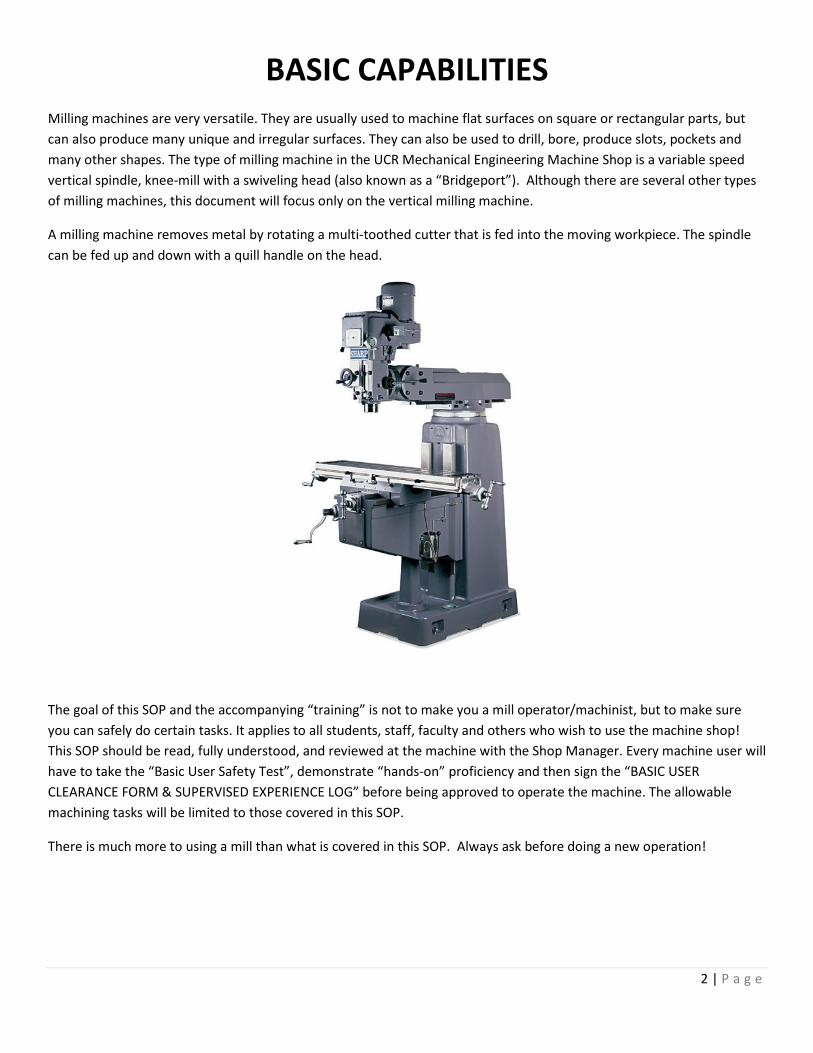
BASIC CAPABILITIES
Milling machines are very versatile. They are usually used to machine flat surfaces on square or rectangular parts, but
can also produce many unique and irregular surfaces. They can also be used to drill, bore, produce slots, pockets and
many other shapes. The type of milling machine in the UCR Mechanical Engineering Machine Shop is a variable speed
vertical spindle, knee-mill with a swiveling head (also known as a “Bridgeport”). Although there are several other types
of milling machines, this document will focus only on the vertical milling machine.
A milling machine removes metal by rotating a multi-toothed cutter that is fed into the moving workpiece. The spindle
can be fed up and down with a quill handle on the head.
The goal of this SOP and the accompanying “training” is not to make you a mill operator/machinist, but to make sure
you can safely do certain tasks. It applies to all students, staff, faculty and others who wish to use the machine shop!
This SOP should be read, fully understood, and reviewed at the machine with the Shop Manager. Every machine user will
have to take the “Basic User Safety Test”, demonstrate “hands-on” proficiency and then sign the “BASIC USER
CLEARANCE FORM & SUPERVISED EXPERIENCE LOG” before being approved to operate the machine. The allowable
machining tasks will be limited to those covered in this SOP.
There is much more to using a mill than what is covered in this SOP. Always ask before doing a new operation!
3 | P a g e
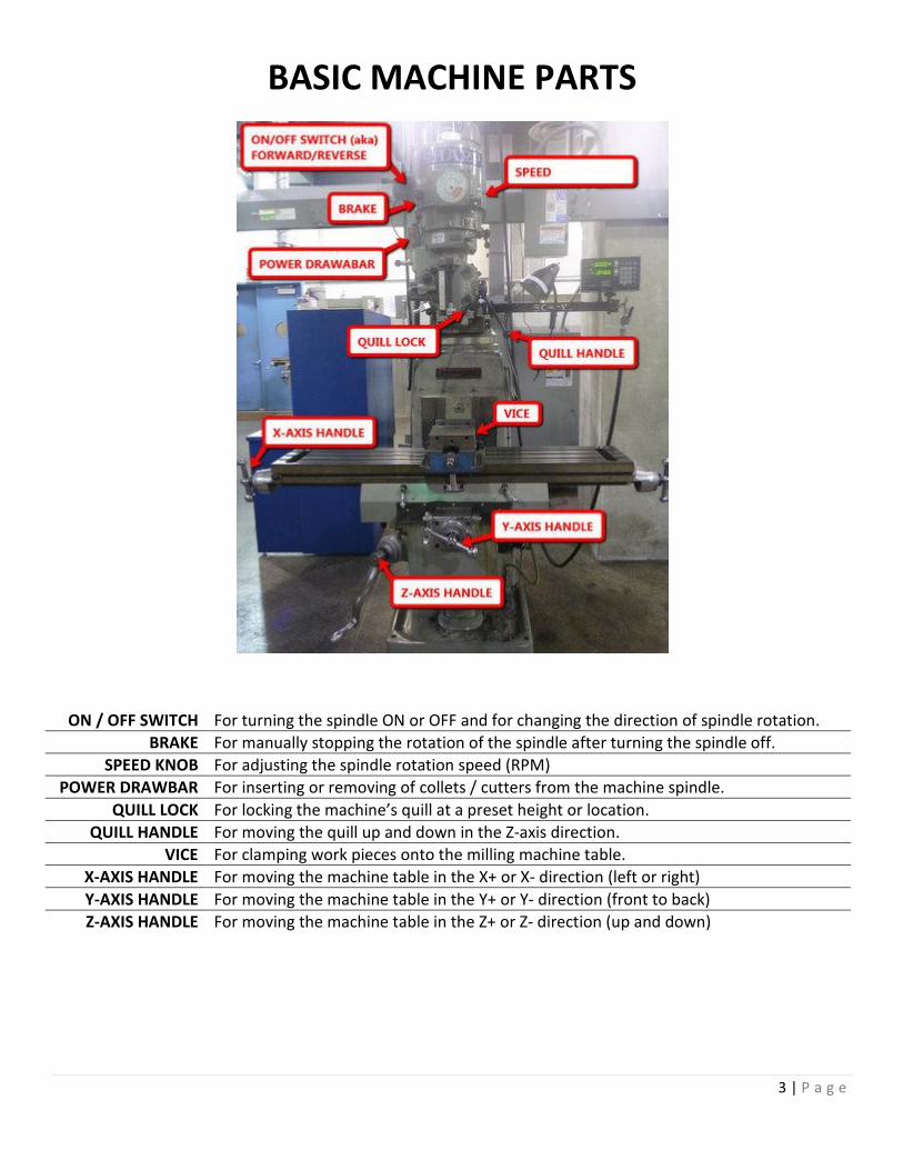
BASIC MACHINE PARTS
ON / OFF SWITCH For turning the spindle ON or OFF and for changing the direction of spindle rotation.
BRAKE For manually stopping the rotation of the spindle after turning the spindle off.
SPEED KNOB For adjusting the spindle rotation speed (RPM)
POWER DRAWBAR For inserting or removing of collets / cutters from the machine spindle.
QUILL LOCK For locking the machine’s quill at a preset height or location.
QUILL HANDLE For moving the quill up and down in the Z-axis direction.
VICE For clamping work pieces onto the milling machine table.
X-AXIS HANDLE For moving the machine table in the X+ or X- direction (left or right)
Y-AXIS HANDLE For moving the machine table in the Y+ or Y- direction (front to back)
Z-AXIS HANDLE For moving the machine table in the Z+ or Z- direction (up and down)

4 | P a g e
SAFETY RULES
For everyone using the milling machines, without exceptions!
1. Safety glasses worn at all times, by everyone in the shop!
2. No long sleeves, no gloves, no open toe shoes, and no jewelry or watches.
3. Long hair must be secured behind your head!
4. Become thoroughly familiar with the machine before operating it!
5. When in doubt, always ask a supervisor or shop manager!
6. Never use the mill (or any other equipment) when tired or rushed for time!
7. Only attempt work that you have been approved to do and are comfortable doing!
8. Get additional training, refresher courses and approval as necessary! ASK FOR HELP!
9. Never reach anywhere over, around or near any rotating cutter(s)!
10. Stop the machine every time the cutter is not cutting, not being used, or you are
changing tools/parts!
11. Only remove chips using gentle air blasts or chip brushes, be aware of cutting tools!
12. Use a chip shield to keep chips from hitting you and/or others in the area!
13. Keep ALL rags and tools away from the machine and off machine table(s) during use!
14. Be sure the holding device and workpiece are both securely clamped!
15. Always make sure that the cutting tool is sharp, at the correct height and has the
proper clearance.
16. Do not be distracted or talk to others when operating the machine.
17. Do not walk away from running machines. Turn them off every time!
18. Report ALL broken tools, cutters and/or malfunctioning equipment to a supervisor or
the shop manager!
19. Keep your work area clean (including the floor), free of chips and any oils!
20. Students are NOT ALLOWED to teach other students in the use of the mill!
21. Leave the entire machine CLEANER than when you found it!
Be safe, ask if unsure, use your common sense, and look out for the safety of others.
5 | P a g e
USING THE MACHINE
1. Tramming the Head with the help of a Supervisor or Shop Manager.
The head of a vertical milling machine can be tilted from side to side and from front to back. This allows for versatility of
the machine, but these adjustments can drift. Occasionally, one should check and adjust the head so that the spindle will
be normal to the plane of the table. To check, install a dial indicator into the tramming bar, and install the dial indicator
on the other end of the bar. The indicator face should be facing up and the probe at 45 degree to the table. Lower the
spindle until the dial indicator contacts the table then registers about one half of a revolution. Set the dial indicator is
toward you and set the bezel to zero. Rotate the spindle by hand 180 degrees. If the dial indicator still reads zero, the
spindle is aligned front to back. If not, adjust the head until the dial reads half of the original reading and iterate the
entire process until the error falls within acceptable limits. Repeat the process with the dial displaced left and right to
alight the head side to side.
2. Squaring the Vise. Check before every job, don’t assume it’s aligned or tightened!
Work on a milling machine is most often held in a vise clamped onto the bed. To make sure the parts we make are
square and parallel, the vice must be aligned with the X travels of the machine. To do this, mount the vise on the bed
and secure it with T-bolts, but only lightly so as to permit adjustment of the orientation of the vise. Mount a dial
indicator in the spindle of the machine with the probe facing away from you. Lower the spindle and run the bed of the
table back until the fixed (back) jaw of the vise is in contact with the indicator and further until the indicator registers
one half of a revolution. Set the bezel to zero. Use the manual cross feed to run the indicator across the face of the vise.
If the vise is squared, the indictor will remain at zero. If the dial indicator does not read zero, tap lightly with a soft
hammer to realign the vise. Repeat this procedure until the dial indicator reads zero through the full travel across the
face of the vise jaw. Tighten down the T-bolts be careful not to change the vise orientation. Recheck the alignment of
the vise.
3. Setting Spindle Speed & High/Low Gearing
Spindle speed is set by turning the speed crank on the right side of the spindle. The spindle must be on and rotating to
adjust the speed. There is a manual display (dial) on the head of the machine that shows the speed in rpm. The spindle
speed dial has two scales, one for low range, and one for high range. The machine is switched between ranges with
“SPEED RANGE” lever on the right side of the machine head. Switching this lever must be done with the spindle not
running! Sometimes, the spindle must be rotated slightly (by hand) to allow the gears to mate properly and allow the
lever to “click” into gear.
6 | P a g e
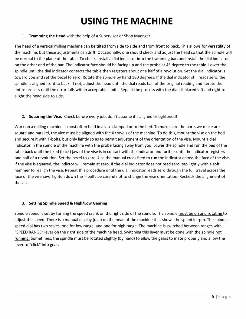
4. Using an Edge Finder
Before doing precise work on a milling machine, one must locate the edges of a part accurately. An edgefinder is
designed to do this on edges with flat vertical surfaces. An edgefinder is composed of two concentric cylinders, spring
loaded together. To use it you must first insert it into the machine with the appropriate collet. The big end of the
edgefinder is held in the collet at least ½ way in. Start the spindle and set the speed to approximately 1,000rpm. Flick
the bottom of the edgefinder to induce a wobble in the smaller diameter. The smaller diameter is usually .200”
diameter. Then, move the part into the tool very slowly. The edge finder will center up, then break out of concentricity
suddenly. At that point, reset the dial indicator or digital readout for that axis of the machine to a value equal the radius
of the edgefinder. Repeat the process at least twice to make sure your edge finding was correct.
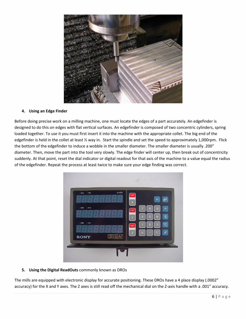
5. Using the Digital ReadOuts commonly known as DROs
The mills are equipped with electronic display for accurate positioning. These DROs have a 4 place display (.0002”
accuracy) for the X and Y axes. The Z axes is still read off the mechanical dial on the Z-axis handle with a .001” accuracy.

7 | P a g e
There are two systems of measurement that the DROs can supply, Incremental and Absolute. Absolute should be used
for the “zero” corner of your part and not be changed during the job. The incremental setting can be “zeroed” as
necessary for use between any two locations, features, holes, etc….
6. Cutting Fluids and their applications.
Different applications and/or materials require slightly different cutting fluids. These fluids are designed to provide the
correct amount of lubricity, cooling, better surface finish, increased tool life and more. All cutting fluids (especially
WS11) should be thoroughly cleaned / removed from the machine when finished! The machine should be dry and a light
“misting” of WD40 applied to the entire vice, tables and machine ways to prevent corrosion.
• Fluids
o WS11 – Water soluble oil. A combination of 5% WS11 oil + 95% water. Resembles “milk”
o A9 Cutting Fluid. Specially designed for aluminum and other soft metals. Green in color.
o MolyDee. A thick, black, heavy cutting fluid for steels and other tough to machine materials.
o WD40. Not a cutting fluid, only use to protect for corrosion on cleaned machines.
• Applications:
o Aluminum & other soft materials tapping: Use A9 cutting fluid. Applied with a drip from the nozzle or
brushed onto the tap.
o Aluminum & other soft materials drilling/milling/boring/etc: Apply liberal amounts of WS11 with an
acid brush or spray bottle
o Steel tapping & heavy cutting: Use MolyDee, applied with a drip or acid brush directly to the tap.
o Steel drilling/milling/boring/etc: Apply liberal amounts of WS11 with an acid brush or spray bottle.
o Plastics: Most do not need any cutting fluids. Correct speeds & feeds are more critical.
7. Cutting Tool Holders. You must match the correct ones!
The only types of tools that are permitted to be used in the manual mills are listed below. The machine operator should
review and learn the information given in the separate [MILL CUTTING TOOLS SOP] to determine when to use what type
of cutting tools. Mill cutting tools can only be held in the machine with a collet or Drill chuck:
8 | P a g e
• In an R8 mill collet, you can hold: End Mills, boring heads, flycutters, shell mills, counterbores.
o Diameter of tool MUST match the size of the collet.
• In a precision drill chuck, you can hold: Drill bits, reamers, countersinks, center drills.
o Do not use keyed or tapered drill chucks in the mill.
8. Removing and Installing Cutting Tools. Easy if done correctly
REMOVNG OR INSTALLING CUTTING TOOLS IS ALWAYS DONE WITH THE MACHINE OFF!!! Make sure that there is
enough room between the quill and workpiece/vice/table (8”-12”) to easily remove/insert the cutting tool and collet.
To remove a tool from a machine WITH a power drawbar installed, move the quill to the highest position and lock it in
place with the quill lock. Hold whatever is in the collet (endmill, drill chuck, etc.) then press and hold the green button
and the red “OUT” button simultaneously (for 3 seconds) on the power drawbar box. This will release the collet and
cutter from the spindle. Hold on to both as you remove them. If you do not hold on to the collet and cutter, they will fall
out and can be damaged.
In order to install a collet and cutter, move the quill to the highest position and lock it in place with the quill lock. Place
the desired milling cutter (or drill chuck) in a collet of the correct diameter. Insert the collet into the spindle. Ensure that
the key way on the collet mates properly with the key in the spindle and is fully inserted. While holding the tool with one
hand, press and hold the green button and the red “IN” button simultaneously (for 3 seconds) on the power drawbar
box.
9. Cleaning the Machine proper procedures for care and feeding
The entire machine must be cleaned after every use. If another user needs the machine, immediately after you, make
sure you discuss who will leave the machine clean. The process is simple and should not take more than 10 minutes.
Make sure you are aware of clock to leave enough time to finish clean-up. The procedure is:
A. Turn off the machine and remove the cutter and collet from the spindle.
B. Put away all your hand, set-up and cutting tools. If not sure where they go, ask a supervisor.
C. Use a brush or light blasts of air to remove the chips from the vice, table and ways.
D. Do not blast the chips and fluids across the shop, use enough force to get the chips to the ground.
E. Brush or vacuum the difficult to reach spots. Wipe the spindle, table, ways, covers, vice, etc…
F. Wipe off ALL cutting fluids and oils from the ENTIRE machine. Top to bottom, machine must be dry.
G. Gently mist the table, ways, vices or chuck(s) with WD40. Pump the central lubrication handle 4x.
H. Sweep the floor and surrounding areas. Chips are to be placed in chip buckets, not regular trash cans.
I. There should be NO visible chips of any size on the machine. Leave it cleaner than when you found it.
10. Unfinished Work and leaving your machine.
A machine may be left set-up with your job ONLY if you will be returning at the next available opportunity. If it is less
than a 2 hour gap, the machine may be left as is, just sweep the floor. If it is to be more than two hours or you are
unsure, the machine must be cleaned (as above) and all tools/cutters/supplies must be put away. Machine set-ups will
9 | P a g e
be broken down after 4 hours or if there is an urgent need, unless other arrangements are made with a supervisor or
shop manager. Make sure you leave a sign with your name, phone number and a time/date when you will be returning
to use the machine.
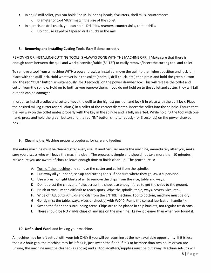
11. Climb vs. Conventional Milling. The wrong choice can do damage!
This section refers to using end mills (or similar tools) and cutting away at the side/wall of a workpiece. When milling,
one should be aware of the difference between conventional and climb milling. In conventional milling, the workpiece is
fed against the rotation of the cutter. The material is being scooped away. This type of cut has lower forces and is
preferred for roughing or heavy cuts. It should be used in most cases. In climb milling, the work moves with the rotation
of the cutter, as if it is “climbing up” the material. Using a climb cut for a “last pass” or a “finish pass” to remove only
.002” - .015” is OK. Using a climb cut for heavy material removal could lead to tool breakage and damaged parts. The
machine operator should review and learn the information given in the separate [MILL CUTTING TOOLS SOP] to
determine what type of end mills to use and when to use them
12. Drilling and use of drill chucks.
Drilling is the process normally described as cutting round holes in a material. Keyless drill chucks are the most common
way to hold drill bits. Bigger drill bits (over .500” dia) can be held in R8 collets ONLY if the drill shank (aka, body) is the
EXACT SAME SIZE as the collet being used. The machine operator should review and learn the information given in the
separate [MILL CUTTING TOOLS SOP] to determine what type of drill bits to use and when to use them. Be aware of the
range capability of the drill chuck, most are .063” to .520” The best way to tighten a “keyless” drill chuck is (with the
machine OFF) hold the machine’s spindle brake and turn the chuck body counter clockwise. Reverse this to release the
drill bit, but make sure you don’t allow the drill bit to fall out!
10 | P a g e
13. Calculating Speeds and Feeds “A happy machine is a quiet machine!”
“Speed” refers to the spindle RPM (Revolutions Per Minute). “Feed or feedrate” refers to the amount you make the
cutting tool move across or into your workpiece (aka, feedrate). Feeds and speeds affect the time to finish a cut, tool
life, finish of the machined surface and power required of the machine. The cutting speed is mostly determined by the
material to be cut and the material of the cutter. Lubricant plays a critical role in cutting. Make sure you use plenty of
the correct type! Broken or abused tools are the responsibility of the user and will have to be replaced at your cost.
To find the right speed for any task, first ask a shop supervisor. If unavailable, use the “Speed vs. Feed” guidelines as a
starting point. The feed rate depends on the width and depth of cut, finish desired and many other variables. THE most
common mistake is to run the feeds or spindle speed too fast!
SPEED VS. FEED - BASIC GUIDELINES
IF THEN
You INCREASE the FEEDRATE too much… You risk taking too big a “bite” and will break the cutter.
You DECREASE the FEEDRATE too much… You risk “rubbing” (not cutting) and will wear out the cutter.
You INCREASE the SPINDLE SPEED too much… You will not cut, but instead burn up the tool with friction.
You DECREASE the SPINDLE SPEED too much Your cut will be very slow.
You find the right balance The machine will be quiet (not screaming or shaking)
You find the right balance You will be making (nice, not discolored) chips.
You find the right balance You will be removing material and the cutter will last!
11 | P a g e
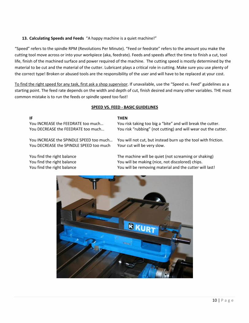
14. USING A VICE for clamping parts.
A precision vice (KURT model 675) is the most common way to hold parts in a milling machine. There are several
considerations that must be taken into account to make sure the part is secure. At first, you should seek guidance from a
supervisor for every setup in a vice and learn by example. Vice stops will enable you to accurately take parts in and out
of the vice, learn how to use them. Most importantly, always get a supervisors advice for unusual shaped parts or set-
ups. Some general guidelines:
A. ALWAYS SHUT OFF THE MACHINE BEFORE DOING ANYTHING IN OR NEAR A VICE.
B. Don’t assume the vice is aligned or tightened down! Always check with an indicator.
C. Always wipe off the vice jaws, parallels and other fixtures when clamping a new part.
D. Always grip at least 50% of the part and in the center of the jaws.
E. Never grip a part at just one end of the vice, unless an identical part is at the other end.
F. Get instruction or supervision!
15. USING PARALLELS in a Kurt vice.
Parallels are used to raise the work above the vice jaws for machining, drilling or other operations. They can set the part
height so the vice jaws will not be hit by your cutting tools and that any drilling operations will not cut into the bottom of
the vice. Make sure you use a matching (height) set. Also be aware of running into the parallels, and constantly check to
see that they have not moved unintentionally. It is a good idea to always check that no chips have fallen on toip of or
underneath the parallels, as this will greatly effect the accuracy of your parts!
16. SQUARING STOCK & FACE MILLING First step in accurate parts
To create a square corner on a part, first orient an already finished edge vertically in the vise and clamp lightly onto the
part. Set a machinist's square against the finished edge and the bottom of the vise. Lightly tap the part with a plastic
hammer to align it with the square. Clamp the vise down securely. Now the top edge of the part is ready to be milled to
horizontal.
It is often necessary to create a flat face on a large part. This is called face milling. Select a sharp, flat bottom, end mill
cutter a little wider than the workpiece so that the facing can be accomplished in one pass. This can work for end mills
up to .750” diameter in size. Beyond that size, you will have to make multiple passes or use a flycutter.
Fly cutting, which is also called single point milling, is one of the most versatile milling operations. It is done with a
single-point cutting tool shaped like a lathe tool bit. It is held and rotated by a fly cutter arbor. You can grind this cutter
to almost any form that you need. It is more economical to grind the desired form on a lathe-type tool bit than to buy a
pre-ground form cutter, which is very expensive and usually suitable only for one particular job.
For milling slots, end mills are an idea tool. They will produce a slot to within two one-thousandths of an inch in one
pass. If greater accuracy is required, use an end mill a little smaller than the desired slot. Measure the slot you produced
and then open it to the desired dimension with a second pass. Note that the depth of cut should not exceed three times
the diameter of the cutter.
12 | P a g e
17. DRILLING, BORING & REAMING Much more accurate than a drill press
The milling machine may be used effectively for drilling, since accurate location of the hole may be secured by means of
table positioning. Spacing holes in a circular path, such as the holes in an index plate, may be accomplished by indexing
with the index head positioned vertically.
Twist drills may be supported in drill chucks fastened in the milling machine spindle or mounted directly in milling
machine collets or adapters. The workpiece to be drilled is fastened to the milling machine table by clamps, vises, or
angle plates.
For boring, there are various types of boring tool holders may be used for boring on the milling machine, the boring
tools being provided with either straight shanks to be held in chucks and holders or taper shanks to fit collets and
adapters. The two attachments most commonly used for boring is the offset boring head, also known as the “Criterion
Boring Head”
The single-edge cutting tool used for boring on the milling machine is the same as a lathe cutter bit. Cutting speeds,
feeds, and depth of cut should be the same as that prescribed for lathe operations.
Boring is usually used for holes bigger than .500” diameter. The most accurate way to finish a hole smaller than .500”
diameter is the process of reaming. Reaming is a process which slightly enlarges a pre-existing hole to a tightly
toleranced diameter. A reamer is similar to a mill bit in that it has several cutting edges arranged around a central shaft.
Reaming is always done after hole drilling. If the hole is drill crooked, the reamer will follow the crooked hole. Reaming
should not be relied upon to correct the location or alignment of a hole. Reamed holes should not intersect with drilled
holes. Its primary purpose is to fine-tune the diameter of the hole. Reaming is most accurate for axially symmetric parts
produced and reamed on a mill. Reamers come in a multitude of sizes.
18. OTHER CONSIDERATIONS to be aware of.
• Never be afraid to ask for help and guidance, that is why the shop supervisor is there! When in doubt, always
ask!
• These are very capable machines, but must be used correctly to avoid damage and accidents. Learn how to use
them correctly, there are no shortcuts in quality and safety!
• Come prepared. Have your material/parts, complete (accurate) drawing(s), a plan of action and list of tools you
will need.
• Cutting tools are VERY expensive and easy to break or dull. You are responsible if they are broken or damaged.
• Don’t leave rags, measuring or other precision tools on the table of the machine. They will get damaged,
contaminated or fall off.
• Double check your set-up before starting any operation. Check for tightness/rigidity, correct speeds/feeds,
obstructions, clamps, etc.
• Re-read the safety rules, your life and health depends on it!