UBL - Under Bed Lift - Future Automationcdn.futureautomation.co.uk/Tech/ubl-instructions.pdf ·...
24
Lift Mechanisms email [email protected] tel: +44 (0) 1438 833577 fax: +44 (0) 1438 833565 ISSUE 004 Installation Instructions UBL - Under Bed Lift Design Highlights -Near Silent Operation -Full Cable Management -Programmable Viewing Height -Wide Range of Screen Mounting Options -Innovative Design Thank you for choosing future automation
-
Upload
vuongkhanh -
Category
Documents
-
view
217 -
download
3
Transcript of UBL - Under Bed Lift - Future Automationcdn.futureautomation.co.uk/Tech/ubl-instructions.pdf ·...

Lift M
echanis
ms
email [email protected] tel: +44 (0) 1438 833577 fax: +44 (0) 1438 833565 ISSUE 004
Installation Instructions
UBL - Under Bed Lift
Design Highlights
-Near Silent Operation
-Full Cable Management
-Programmable Viewing Height
-Wide Range of Screen Mounting Options
-Innovative Design
Thank you for choosing
futureautomation

Intr
od
ucti
on
: S
afe
ty Info
rmation
Page 1 of 22 // email [email protected] tel: +44 (0) 1438 833577 fax: +44 (0) 1438 833565
UBL - Under Bed Lift
Warnings:
1. Read all technical instructions fully before installation and use. It is the installer’s responsibility to ensure that all
documentation is passed on the end user and read fully before operation.
2. Keep all documentation.
3. Heed all warnings.
4. Follow all technical specifications and instructions during installation.
5. Do not use near water unless the product has been specifically designed to do so.
6. Clean only with a dry cloth.
7. Do not defeat the purpose of the polarized or grounding type plug. A polarized plug has two blades, one wider
than the other. A grounding type plug has two blades and a grounding prong. The wide blade or third prong are
provided for your safety. If the provided plug does not fit your outlet, consult an electrician or contact the
manufacturer.
8. Protect the power cord from being walked on or pinched, particularly at plugs, convenience receptacles, and the
point where the exit from the apparatus.
9. Unplug the apparatus during lightning storms or when unused for long periods of time.
10. Only use attachments/accessories specified by the manufacturer.
11. Refer all servicing to qualified personnel. Servicing is required regularly on an annual basis, when the apparatus is
damaged in any way, liquid has been spilled or objects have fallen into the apparatus, the apparatus has been
exposed to rain or moisture, does not operate normally, or has been dropped.
12. To completely disconnect the apparatus form the AC mains, disconnect the power cord plug from the AC
receptacle on the power control box.
13. To prevent overheating, do not cover the apparatus. Install in accordance with the instructions.
14. UK, Ireland and Hong Kong only – The power cord is supplied with a 13A plug having an earthing pin. The
apparatus is earthed and this pin is not required for safety, merely to operate the safety shutter of mains outlet.
15. No naked flames such as lit candles should be placed on the unit.
16. Observe and follow the local regulations when disposing of batteries.
17. Do not expose the unit to dripping or splashing fluids.
18. Do not place objects filled with liquid, such as vases, on the unit.
19. Do not expose the batteries to excessive heat such as sunshine, fire or the like.
20. For all mounted apparatus, the apparatus should be installed on solid wood, bricks, concrete or solid wood
columns and battens.
21. Always turn off power at source before putting on or taking off parts and cleaning.
22. Do not use outdoors unless marked for outdoor use.
23. Exceeding the weight capacity can result in serious personal injury or damage to equipment.
Future Sound & Vision trading as Future Automation intend to make this and all documentation as accurate as possible. However, Future
Automation makes no claim that the information contained herein covers all details, conditions or variations, nor does it provide for every
possible contingency in connection with the installation or use of this product. The information contained in this document is subject to
change without prior notice or obligation of any kind. Future Automation makes no representation of warranty, expressed or implied,
regarding the information contained herein. Future Automation assumes no responsibility for accuracy, completeness or sufficiency of the
information contained in this document.
Safety Disclaimer
Important Safety Instructions
Explanation of graphical symbols
-(Electric Shock Symbol) = The lightning flash within an equilateral triangle is intended to alert you to the presence of un-insulated
“dangerous voltage” within the products enclosure that may be of sufficient magnitude to constitute an electric shock to persons
-(Caution Symbol) = The exclamation point within an equilateral triangle is intended to alert you to the presence of important
operating and maintenance (servicing) instructions in the literature accompanying the product
-(Tools Symbols) = The tools symbol within a coloured square are intended to highlight the required tools necessary for correct and
safe installation of the product. These are intended as a
guide only, and it is at the installer’s discretion as to which tools are used.
WARNING: RISK OF ELECTRIC SHOCK, ONLY AUTHORIZED INSTALLERS TO OPEN THE POWER CONTROL BOX.
WARNING: To reduce the risk of fire or electric shock, do not expose electrical parts to rain or moisture, unless the
product has been specifically designed to do so.
WARNING: Failure to provide adequate structural strengthening, prior to installation can result in serious personal injury or damage to the
equipment. It is the installer’s responsibility to ensure the structure to which the component is affixed can support the four times the
weight of the component.
WARNING: Do not exceed the weight capacity. This can result in serious personal injury or damage to the equipment. It is the installer’s
responsibility to ensure that the total combined weight of all attached components does not exceed that of the maximum figure stated.
WARNING: Failure to provide adequate structural strength for this component can result in serious personal injury or damage to equip-
ment! It is the installer’s responsibility to make sure the structure to which this component is attached can support five times the combined
weight of all equipment. Reinforce the structure as required before installing the component.
Caution
WarningBeware of
Moving Parts
Keep Hands
Clear
Danger
Electricity

Intro
du
ctio
n: C
on
ten
ts
Page 2 of 22 // email [email protected] tel: +44 (0) 1438 833577 fax: +44 (0) 1438 833565
UBL - Under Bed Lift
Contents Page
Introduction
Safety Information 1
Contents 2
Contents 3
Tool Indicator Icons 3
Installation
Parts List
Package Contents 4
Stage 1
Before You Start 5
Mechanism Key Movements 5
Stage 2
Removing the Panels & Uprights 6
Stage 3
Cable Management 7
Stage 4
Cable Management 8
Stage 5
Positioning and Fixing the Mechanism 9
Stage 6
Checking Mechanism Movement 10
Stage 7
Mounting the Screen 11
Stage 8
Carriage Switch Adjustment 12
Stage 9
Up Hinge Switch Adjustment 13
Stage 10
Down Hinge Switch Adjustment 14
Stage 9
Telescopic Height Adjustment 15
Stage 10
Final Fixings 16
Electrical Connections
Contact Closure 17
IR Controls 18
RF Controls 19
Intr
od
ucti
on
: C
onte
nts
/ T
ool In
dic
ato
r
Page 3 of 22 // email [email protected] tel: +44 (0) 1438 833577 fax: +44 (0) 1438 833565
UBL - Under Bed Lift
Tool Indicator Icons
1. 2. 3. 4. 5. 6.
1. - Drill 3. - Allen Keys 5. - Screwdrivers 7. - Pencil
2. - Tape measure 4. - Spirit Level 6. - Spanners 8. - Saw
7. 8.
Product Warranty
This product carries a warranty that covers the cost of labour and spare parts incurred by any defects in materials and workmanship under normal use
during a two year period from date of purchase. Support for any problems that are not hardware faults are excluded from the warranty entitlement.
This warranty does not affect your statutory consumer rights.
The following is excluded from warranty service:
• Malfunctioning caused by misuse or damage, accidental or otherwise, or service modification by persons not authorised by Future Automation,
or the use of any non Future Automation supplied parts;
• Any electrical, or other environmental work external to your Future Automation mechanism including power cuts, surges or lightning strikes;
• Additional items not supplied by Future Automation although they may have been supplied together by the retailer;
• Any 3rd party software products controlling your mechanism;
• Any transfer of ownership. Warranty is provided only to the initial purchaser;
• Compensation for loss of use of the product, and consequential loss of any kind;
• Use of the product over the specified weight capacity;
• Any damage to products during transit that is not checked and notified as “unchecked” or “damaged” upon receipt of delivery.
Any part of your system that needs to be replaced during a warranty repair becomes the property of Future Automation.
Contents Page
Operations
IR Control 16
IR Operation 16
Storing Positions 16
Changing Batteries 16
RF Control 17
RF Operation 17
Trouble Shooting 18
Technical Overview 19
Ins
talla
tion
: Pa
cka
ge
Co
nte
nts
Page 4 of 22 // email [email protected] tel: +44 (0) 1438 833577 fax: +44 (0) 1438 833565
UBL - Under Bed Lift
1.3
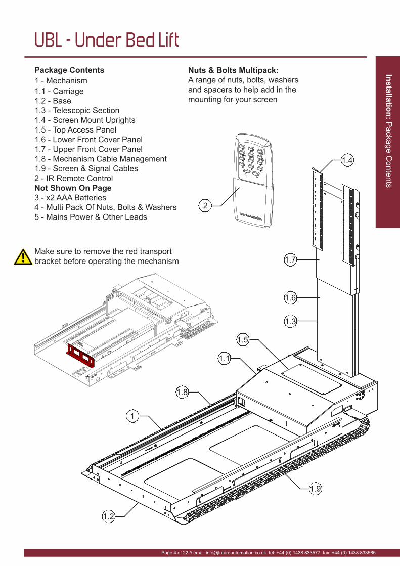
Nuts & Bolts Multipack:
A range of nuts, bolts, washers
and spacers to help add in the
mounting for your screen
1.5
2
Package Contents
1 - Mechanism
1.1 - Carriage
1.2 - Base
1.3 - Telescopic Section
1.4 - Screen Mount Uprights
1.5 - Top Access Panel
1.6 - Lower Front Cover Panel
1.7 - Upper Front Cover Panel
1.8 - Mechanism Cable Management
1.9 - Screen & Signal Cables
2 - IR Remote Control
Not Shown On Page
3 - x2 AAA Batteries
4 - Multi Pack Of Nuts, Bolts & Washers
5 - Mains Power & Other Leads
1
1.1
1.4
1.8
1.6
1.7
1.2
1.9
Make sure to remove the red transport
bracket before operating the mechanism

Ins
talla
tio
n:
Sta
ge
1
Page 5 of 22 // email [email protected] tel: +44 (0) 1438 833577 fax: +44 (0) 1438 833565
UBL - Under Bed Lift
Before you start
Prior to installation, check the following:
-The product is in good condition and is all connected
-No damage to any parts
-Wiring is all secure
-The mechanism is in the closed position
-Test the mechanism by running it up and down
-Refer to pages 17-19 for mechanism control
IN Position
OUT Position
EXTENDED
Position
HINGED Position
Mechanism key
movement positions:

Ins
talla
tion
: Sta
ge
2
Page 6 of 22 // email [email protected] tel: +44 (0) 1438 833577 fax: +44 (0) 1438 833565
UBL - Under Bed Lift
Removing the Panels & Uprights
Make sure mechanism is in the full OUT position.
First remove the screen uprights by removing X4
locking bolts on the mount toggles so they can be
un-hooked as shown.
Remove the top access panel by removing the X4
bolts shown.
Screen uprights
Top access
panel

Client Cable
Management
Ins
talla
tio
n:
Sta
ge
3
Page 7 of 22 // email [email protected] tel: +44 (0) 1438 833577 fax: +44 (0) 1438 833565
UBL - Under Bed Lift
Cable Management
Run the screen cables down
the left side of the base in the
client cable management chain
to the carriage.
Product Cable Management
(for mechanism cables)
Telescopic Cable
Management
Cable Entry
Hole
Once the cables are passed through
the cable entry hole, make sure they
are secured to the cable tie bracket
immediately inside the carriage.
Cable Tie
Bracket
Ins
talla
tion
: Sta
ge
4
Page 8 of 22 // email [email protected] tel: +44 (0) 1438 833577 fax: +44 (0) 1438 833565
UBL - Under Bed Lift
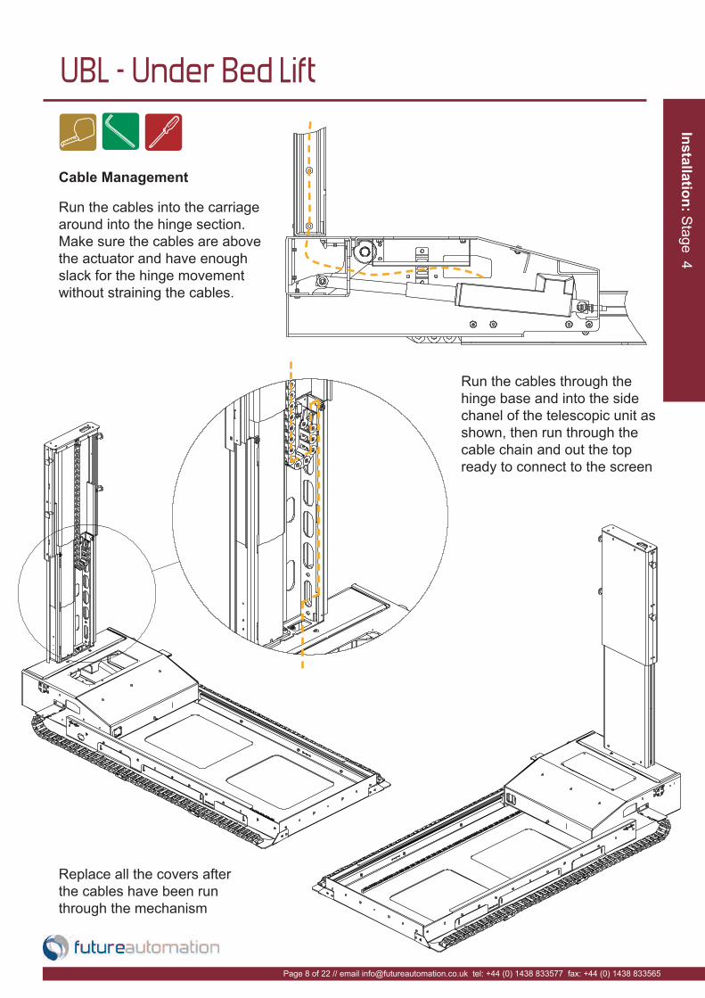
Cable Management
Run the cables into the carriage
around into the hinge section.
Make sure the cables are above
the actuator and have enough
slack for the hinge movement
without straining the cables.
Run the cables through the
hinge base and into the side
chanel of the telescopic unit as
shown, then run through the
cable chain and out the top
ready to connect to the screen
Replace all the covers after
the cables have been run
through the mechanism

Ins
talla
tio
n:
Sta
ge
5
Page 9 of 22 // email [email protected] tel: +44 (0) 1438 833577 fax: +44 (0) 1438 833565
UBL - Under Bed Lift
Positioning and Fixing the Mechanism
First run the mechanism back into the IN
position.
Slide the mechanism under the bed and fix
in place through the slots in the fixing
brackets on each side of the mechanism.
Slotted holes
for adjustment
back and forth
Mechanism height
adjustment in case of
rugs or thick carpets
Fixing
brackets

Insta
llatio
n: S
tage 6
Page 10 of 22 // email [email protected] tel: +44 (0) 1438 833577 fax: +44 (0) 1438 833565
UBL - Under Bed Lift
Checking Mechanism Movement
Run the mechanism into the OUT position checking the clearance at all times. Make sure
it reaches the OUT position without hitting any obstacles and has suitable clearance from
the floor.
Under Bed - Out Position
Under Bed - Hinged Position
Under Bed - Extended Position
Under Bed - In Position
Make sure there will be
sufficient clearance for
the screen and mount
uprights when the
mechanism performs
the hinging motion.
90mm [3.5”]
+ Foot Board Thickness
Ins
talla
tio
n:
Sta
ge
7
Page 11 of 22 // email [email protected] tel: +44 (0) 1438 833577 fax: +44 (0) 1438 833565
UBL - Under Bed Lift
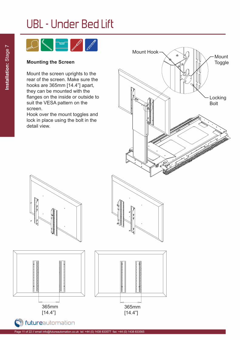
Mounting the Screen
Mount the screen uprights to the
rear of the screen. Make sure the
hooks are 365mm [14.4”] apart,
they can be mounted with the
flanges on the inside or outside to
suit the VESA pattern on the
screen.
Hook over the mount toggles and
lock in place using the bolt in the
detail view.
365mm
[14.4”]365mm
[14.4”]
Mount
Toggle
Mount Hook
Locking
Bolt
Ins
talla
tion
: Sta
ge
8
Page 12 of 22 // email [email protected] tel: +44 (0) 1438 833577 fax: +44 (0) 1438 833565
UBL - Under Bed Lift
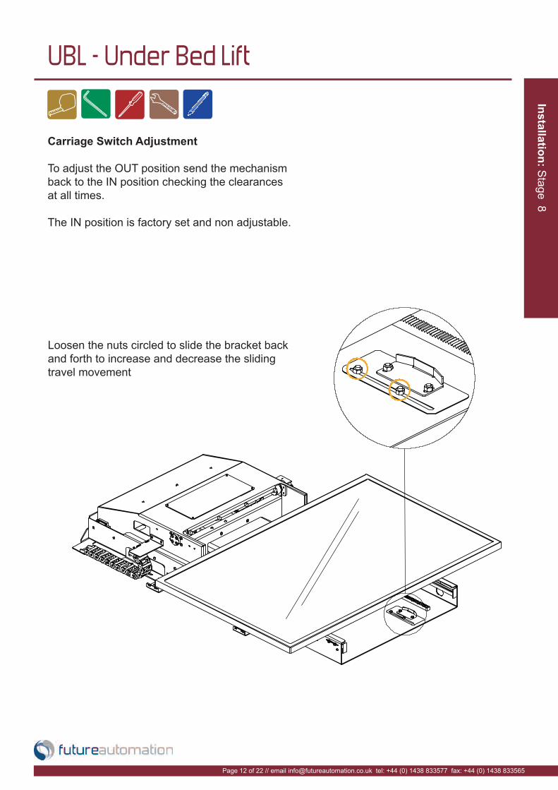
Carriage Switch Adjustment
To adjust the OUT position send the mechanism
back to the IN position checking the clearances
at all times.
The IN position is factory set and non adjustable.
Loosen the nuts circled to slide the bracket back
and forth to increase and decrease the sliding
travel movement

Ins
talla
tio
n:
Sta
ge
9
Page 13 of 22 // email [email protected] tel: +44 (0) 1438 833577 fax: +44 (0) 1438 833565
UBL - Under Bed Lift
Up Hinge Adjustment
To adjust the hinge UP position run the mechanism fully out, under the carriage are
two nuts which hold the out switch bracket. Loosen the nut on the slot and slide up or
down to adjust the UP position angle.

Ins
talla
tion
: Sta
ge
10
Page 14 of 22 // email [email protected] tel: +44 (0) 1438 833577 fax: +44 (0) 1438 833565
UBL - Under Bed Lift
Down Hinge Adjustment
To adjust the hinge DOWN position run the mechanism to the fully out position. Under
the carriage is the hinge DOWN position bracket which is secured in place with 2 nuts
shown in the detail view. Loosen these nuts and slide the bracket back and forth to alter
the DOWN hinge position. Run the mechanism IN to see how the adjustment has
changed the hinge DOWN angle.
Insta
llati
on
: S
tage 1
1
Page 15 of 22 // email [email protected] tel: +44 (0) 1438 833577 fax: +44 (0) 1438 833565
UBL - Under Bed Lift
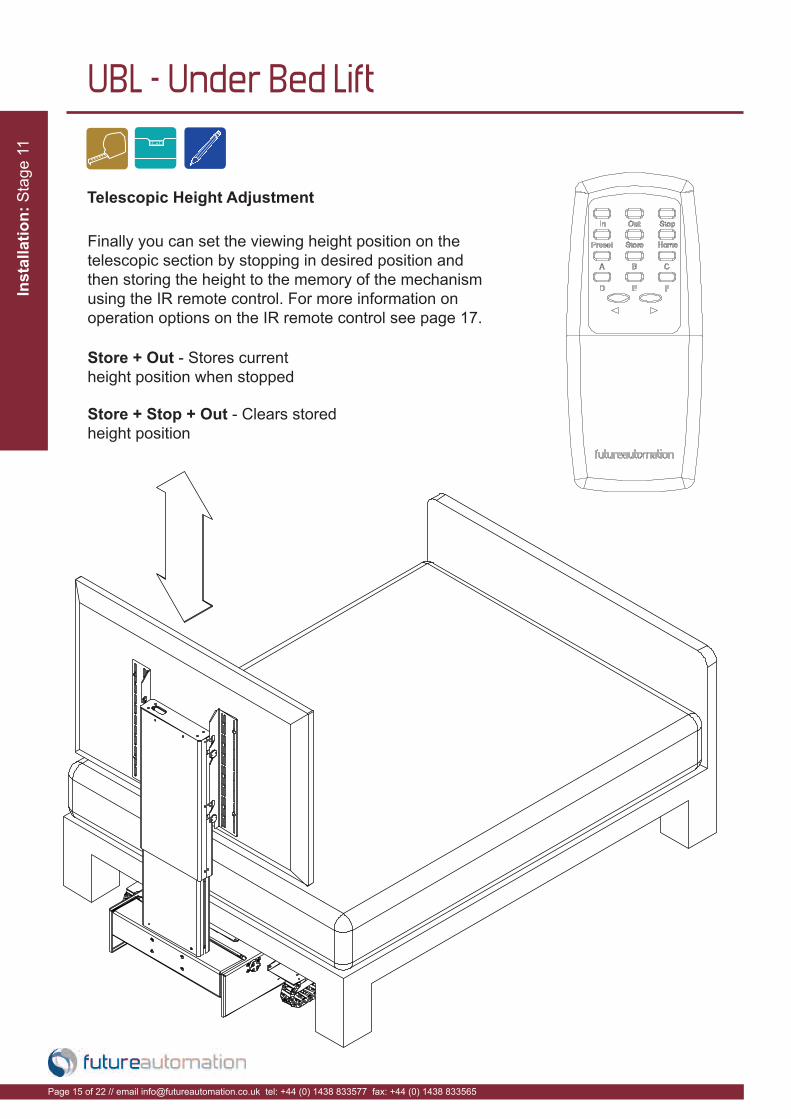
Telescopic Height Adjustment
Finally you can set the viewing height position on the
telescopic section by stopping in desired position and
then storing the height to the memory of the mechanism
using the IR remote control. For more information on
operation options on the IR remote control see page 17.
Store + Out - Stores current
height position when stopped
Store + Stop + Out - Clears stored
height position
Ins
talla
tion
: Sta
ge
12
Page 16 of 22 // email [email protected] tel: +44 (0) 1438 833577 fax: +44 (0) 1438 833565
UBL - Under Bed Lift
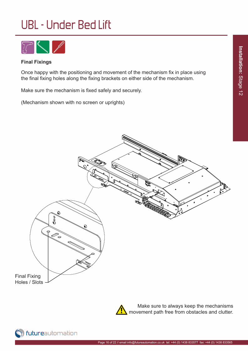
Final Fixings
Make sure to always keep the mechanisms
movement path free from obstacles and clutter.
Once happy with the positioning and movement of the mechanism fix in place using
the final fixing holes along the fixing brackets on either side of the mechanism.
Make sure the mechanism is fixed safely and securely.
(Mechanism shown with no screen or uprights)
Final Fixing
Holes / Slots
Insta
llati
on
: E
lectr
ical C
onnection
Page 17 of 22 // email [email protected] tel: +44 (0) 1438 833577 fax: +44 (0) 1438 833565
UBL - Under Bed Lift
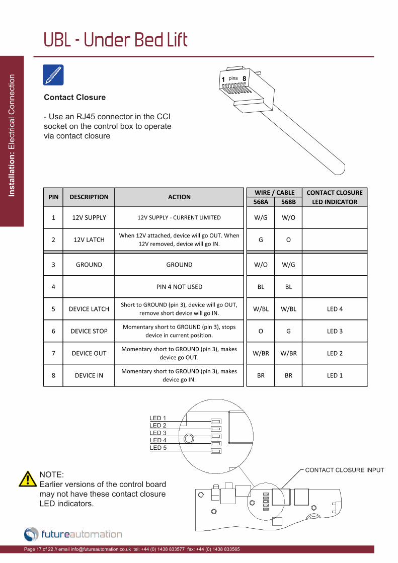
Contact Closure
- Use an RJ45 connector in the CCI
socket on the control box to operate
via contact closure
LED 1
LED 2
LED 3
LED 4
LED 5
CONTACT CLOSURE INPUTNOTE:
Earlier versions of the control board
may not have these contact closure
LED indicators.
568A 568B
1 12V SUPPLY 12V SUPPLY - CURRENT LIMITED W/G W/O
2 12V LATCH When 12V attached, device will go OUT. When 12V removed, device will go IN. G O
3 GROUND GROUND W/O W/G
4 PIN 4 NOT USED BL BL
5 DEVICE LATCH Short to GROUND (pin 3), device will go OUT, remove short device will go IN. W/BL W/BL LED 4
6 DEVICE STOP Momentary short to GROUND (pin 3), stops device in current position. O G LED 3
7 DEVICE OUT Momentary short to GROUND (pin 3), makes device go OUT. W/BR W/BR LED 2
8 DEVICE IN Momentary short to GROUND (pin 3), makes device go IN. BR BR LED 1
PIN DESCRIPTION ACTION WIRE / CABLE CONTACT CLOSURE LED INDICATOR

Insta
llatio
n: IR
Contro
l
Page 18 of 22 // email [email protected] tel: +44 (0) 1438 833577 fax: +44 (0) 1438 833565
UBL - Under Bed Lift
Step 1 Step 2fa_in Device IN
fa_out Device OUTfa_stop Device STOPfa_store fa_c Store height position
fa_b Clears height
COMMAND ACTION
RS232
- Use an RJ25 connector in the socket marked
RS232 on the control box to operate using RS232
Details
Baud rate: 9600
Stop bit: 1
Parity: None
Databits: 8
Pin 1: RX
Pin 6 : TX
Pin 3 & 4: GROUND
Pin 2: TX
Pin 3: RX
Pin 5: GROUND
IMPORTANT
Ensure protocol is entered exactly
as written.
RJ25 9 PIN D
PIN 1: RX TO PIN 2: TX
PIN 6: TX TO PIN 3: RX
PIN 3: GROUND TO PIN 5: GROUND
PIN 4: GROUND TO PIN 5: GROUND

Insta
llati
on
: R
F C
ontr
ol
Page 19 of 22 // email [email protected] tel: +44 (0) 1438 833577 fax: +44 (0) 1438 833565
UBL - Under Bed Lift
Future Automation IR
Remote Controller
needs x2 AAA batteries
which are provided
within the packaging
Replacing batteries
Out - Brings the
mechanism out from
under the bed
Stop - Will stop
the operation at
any position
Operation buttons for the IR remote
In - Brings the mechanism
under the bed
Store + Out - Stores current height position when stopped
Store + Stop + Out - Clears
stored height position
Note
Only buttons indicated are
functional with the product.
Any button pressed when in
motion mechanism will stop.

Tro
ub
le S
ho
otin
g:
Page 20 of 22 // email [email protected] tel: +44 (0) 1438 833577 fax: +44 (0) 1438 833565
UBL - Under Bed Lift
For information on our products please refer to our web site -
www.futureautomation.co.uk
or for questions on installations and our product range please
phone us on - +44(0) 1438 833577 and ask for our technical
support department
UBL Under Bed Lift - Trouble shooting guide

Te
ch
nic
al o
ve
rvie
w:
Page 21 of 22 // email [email protected] tel: +44 (0) 1438 833577 fax: +44 (0) 1438 833565
UBL - Under Bed Lift
A general technical overview of the UBL actuator lift
UBLProduct Dimensions (W,D,H When Closed)
915x1500x220mm [36x59.1x8.7"]
Weight (Kg) 80Kg [176.4lb]
Power Consumption Max 100W
Power Consumption On Standby
1.5W
Lifting Capacity (Kg) 40Kg [88.2lb]
Standard Colour Black
Horizontal Movement 1200mm [47.3"]
Telescopic Movement 585mm [23"]
Max Television Size (W,H,D)
1250x800x70mm [49.2x31.5x2.8"]
ControlIR Remote, RF Remote,
Contact Closure & RS232
Power Supply 240V or 110V
Control Of 3rd Party Product
Yes
Output Power Supply Yes (12V)
Control Box Size (W,D,H) 152x200x55mm [6x7.9x2.2"]
Shipping Details
Dimensions (W,D,H)1870x1100x500mm [73.6x43.3x19.7"]
Weight (Kg) 120Kg [264.6lb]

Page 22 of 22 // email [email protected] tel: +44 (0) 1438 833577 fax: +44 (0) 1438 833565
UBL - Under Bed Lift
Notes...

Future Automation
Unit 2 Kimpton Enterprise Park
Claggy Road
Kimpton
Hertfordshire
SG4 8HP
United Kingdom
Tel: +44 (0) 1438 833 577
Fax: +44 (0) 1438 833 565
Email: [email protected]
www.futureautomation.co.uk


![Universal Business Language Version 2docs.oasis-open.org/ubl/cs1-UBL-2.1/UBL-2.1.pdf · OASIS Universal Business Language TC Chairs: Jon Bosak (bosak@pinax.com), Individual ... [UBL-2.1]](https://static.fdocuments.in/doc/165x107/5e7065bd965725432c6cc8bd/universal-business-language-version-2docsoasis-openorgublcs1-ubl-21ubl-21pdf.jpg)