UAV Flight in Shared Airspace
14
Research Article A Conflict Risk Analysis of MAV\UAV Flight in Shared Airspace ChaoYu Xia , 1,2 Chun-Rong Yang, 1,2 Kang Xue , 1 HanBing Yan, 1,2 JianHua Zhong, 1,2 and Qiu Jun 1,2 1 The 2nd Research Institute, Civil Aviation Administration of China, Chengdu 610041, China 2 Chengdu Civil Aviation Air Traffic Control Science & Technology Co., Ltd., Chengdu 610041, China Correspondence should be addressed to ChaoYu Xia; [email protected] and Kang Xue; [email protected] Received 9 September 2021; Revised 2 October 2021; Accepted 8 October 2021; Published 3 November 2021 Academic Editor: Chen Pengyun Copyright © 2021 ChaoYu Xia et al. This is an open access article distributed under the Creative Commons Attribution License, which permits unrestricted use, distribution, and reproduction in any medium, provided the original work is properly cited. The intelligent auxiliary decision-making (IADM) is emerging as a feasible solution for air traffic control (ATC) to reduce undesirable conflicts in shared airspace; meanwhile, unmanned aerial vehicles (UAVs) can be operated with enhanced efficiency and safety using IADM. This paper presents the conflict risk framework of the MAV\UAV flight that improves flight safety of MAVs and UAVs in shared airspace. This is accomplished by focusing on two steps: First, determine the minimum safety communication interval between the UAV and controller; second, build a conflict risk model to detect which decision mechanism will minimize risk. Our approach provides a standard model to start with to improve IADM and allow engineers to focus on the operational purpose of MAV/UAV. Results show that our work presented here is practical and straightforward, and it brings an evident engineering application prospect. 1. Introduction Unmanned aerial vehicles (UAVs) are widely used in civilian industries, especially in remote sensing, and foreign object detection has attracted considerable attention [1, 2]. As a report goes, some UAVs can even fly at altitudes of tens of thousands of meters and has a range of more than 10,000 kilometers [3]. In recent, multimodal airport group opera- tion is also gradually open to general aviation. However, UAVs can only rely on a notice to airmen (NO-TAM) for independent operation [4]. Specifically, UAVs operate pri- marily in an isolated airspace to prevent flight collisions; there is no doubt that this approach lowers the efficiency of airspace utilization. The goal is obviously increasing traffic volumes in air- space, especially in the terminal area. Thus, sharing flight is a possible solution to the UAV industry. The shared air- space refers to a controlled airspace where all aircraft, including UAVs and manned aerial vehicles (MAVs), can apply for use. For the further better development, new ATC technologies have been studied, such as trajectory- based operation (TBO), situation awareness (SA), and intel- ligent auxiliary decision-making (IADM) [5–7]. However, detecting future conflicts timely and accurately and provid- ing effective relief strategies are the critical issues related to shared-airspace safety. In addition, UAVs violate minimum vertical and horizontal separation standards, and it can pose a serious threat to the safety of MAV transportation. So far, little work has focused on conflict detection in shared air- space. Most of the work targets on UAV obstacle avoidance only. Radmanesh et al. generated collision-free 3D trajecto- ries for multiple UAVs operating in shared airspace based on a partial differential equation (PDE) and modeling the porosity values as a function of the risk of conflict [8]. Ho et al. used preflight conflict detection, and resolution (CDR) methods generate to conflict-free paths for a poten- tially large number of UAVs before actual takeoff [9]. Based on the established protect zone, the closest point of approach (CPA) strategy is employed by Shi et al. to detect potential conflicts [10]. Wang et al. proposed a three-layered collision avoidance system integrating conflict detection procedures [11]. Also, there are several existing trajectory planning approaches that have been introduced in the literature, such as [12]; the UAV optimal path in the Euclidean 3D space is determined through an optimization problem of maximiz- ing the coalition head’s total energy availability. These Hindawi International Journal of Aerospace Engineering Volume 2021, Article ID 1692896, 14 pages https://doi.org/10.1155/2021/1692896
Transcript of UAV Flight in Shared Airspace
Research ArticleA Conflict Risk Analysis of MAV\UAV Flight in Shared Airspace
ChaoYu Xia ,1,2 Chun-Rong Yang,1,2 Kang Xue ,1 HanBing Yan,1,2 JianHua Zhong,1,2
and Qiu Jun1,2
1The 2nd Research Institute, Civil Aviation Administration of China, Chengdu 610041, China2Chengdu Civil Aviation Air Traffic Control Science & Technology Co., Ltd., Chengdu 610041, China
Correspondence should be addressed to ChaoYu Xia; [email protected] and Kang Xue; [email protected]
Received 9 September 2021; Revised 2 October 2021; Accepted 8 October 2021; Published 3 November 2021
Academic Editor: Chen Pengyun
Copyright © 2021 ChaoYu Xia et al. This is an open access article distributed under the Creative Commons Attribution License,which permits unrestricted use, distribution, and reproduction in any medium, provided the original work is properly cited.
The intelligent auxiliary decision-making (IADM) is emerging as a feasible solution for air traffic control (ATC) to reduceundesirable conflicts in shared airspace; meanwhile, unmanned aerial vehicles (UAVs) can be operated with enhancedefficiency and safety using IADM. This paper presents the conflict risk framework of the MAV\UAV flight that improves flightsafety of MAVs and UAVs in shared airspace. This is accomplished by focusing on two steps: First, determine the minimumsafety communication interval between the UAV and controller; second, build a conflict risk model to detect which decisionmechanism will minimize risk. Our approach provides a standard model to start with to improve IADM and allow engineersto focus on the operational purpose of MAV/UAV. Results show that our work presented here is practical and straightforward,and it brings an evident engineering application prospect.
1. Introduction
Unmanned aerial vehicles (UAVs) are widely used in civilianindustries, especially in remote sensing, and foreign objectdetection has attracted considerable attention [1, 2]. As areport goes, some UAVs can even fly at altitudes of tens ofthousands of meters and has a range of more than 10,000kilometers [3]. In recent, multimodal airport group opera-tion is also gradually open to general aviation. However,UAVs can only rely on a notice to airmen (NO-TAM) forindependent operation [4]. Specifically, UAVs operate pri-marily in an isolated airspace to prevent flight collisions;there is no doubt that this approach lowers the efficiencyof airspace utilization.
The goal is obviously increasing traffic volumes in air-space, especially in the terminal area. Thus, sharing flightis a possible solution to the UAV industry. The shared air-space refers to a controlled airspace where all aircraft,including UAVs and manned aerial vehicles (MAVs), canapply for use. For the further better development, newATC technologies have been studied, such as trajectory-based operation (TBO), situation awareness (SA), and intel-ligent auxiliary decision-making (IADM) [5–7]. However,
detecting future conflicts timely and accurately and provid-ing effective relief strategies are the critical issues related toshared-airspace safety. In addition, UAVs violate minimumvertical and horizontal separation standards, and it can posea serious threat to the safety of MAV transportation. So far,little work has focused on conflict detection in shared air-space. Most of the work targets on UAV obstacle avoidanceonly. Radmanesh et al. generated collision-free 3D trajecto-ries for multiple UAVs operating in shared airspace basedon a partial differential equation (PDE) and modeling theporosity values as a function of the risk of conflict [8]. Hoet al. used preflight conflict detection, and resolution(CDR) methods generate to conflict-free paths for a poten-tially large number of UAVs before actual takeoff [9]. Basedon the established protect zone, the closest point of approach(CPA) strategy is employed by Shi et al. to detect potentialconflicts [10]. Wang et al. proposed a three-layered collisionavoidance system integrating conflict detection procedures[11]. Also, there are several existing trajectory planningapproaches that have been introduced in the literature, suchas [12]; the UAV optimal path in the Euclidean 3D space isdetermined through an optimization problem of maximiz-ing the coalition head’s total energy availability. These
HindawiInternational Journal of Aerospace EngineeringVolume 2021, Article ID 1692896, 14 pageshttps://doi.org/10.1155/2021/1692896
results are widely used in low-altitude airspace. Unfortu-nately, these studies are independent, lacking of takingMAVs impact into consideration.
This article considers the conflict risk analytical frame-work of MAV\UAV flight in shared airspace as a main sub-ject of the study. This work is aimed at exploring whichdecision mechanisms are conducted to minimize the proba-bility of conflict risk. Two steps are required for a satisfiedoutcome: first, determining the minimum safety intervalbetween UAV communication lag-time and controllerresponse lag-time; second, based on the minimum securityinterval, build a conflict risk model intelligently detectingwhich decision mechanism has minimized the probabilityof conflict risk. The result points out the advantages andpracticability of adjusting parameters such as steering angle,pitch angle, and flight speed, to quickly identify conflict risk.Moreover, our work can be applied to the design of theIADM decision system in engineering, which guarantees safeflight in shared airspace. Our research has a wide range ofapplications, such as risk assessment for UAS logistic deliv-ery under UAS traffic management environment [13] andconstrained urban airspace design for large-scale drone-based delivery traffic [14].
2. Preliminaries
The past few decades have witnessed a dramatic change inthe UAV field for civil aviation. UAVs used for openingshared airspace becomes an inevitable trend [15]. However,air traffic control (ATC) in shared airspace is facing safetychallenges and enhancing efficiency [16]. In the section, weanalyze the minimum safety interval between UAVs andMAVs by communication lag-time, as well as a brief demon-stration of the conflict relief scheme.
2.1. Situation Awareness. In shared airspace, the UAVs musthave a function of situation awareness. The situation aware-ness means that UAVs gain airspace information which canreflect the outside authentic scenery through sensors andcomplete the overall comprehension including the assess-ment and prediction of the situation. Specific methods areas follows, for cooperative objects, the UAVs can gain flightinformation of other aircrafts or vehicles by Traffic ConflictAvoidance System (TCAS), Automatic DependentSurveillance-Broadcast (ADS-B), and responder [17, 18].For noncooperative objects, the UAVs can judge riskthrough noncooperative sensors, such as inertial measure-ment unit (IMU), laser range finder (LRF), and stereoscopiccamera [19]. Then, the analysis module extracts relevant air-space data, processes explicit and implicit information, andconducts situation representation. Finally, the decision mod-ule is generated on the basis of situation representation, out-putting situational assessment, and situation predictionresults. At the same time, the situation information is trans-mitted to the UAV ground control station and related con-trol departments. This process usually contains complexdata processing flow and information exchange, includingthe UAV prediction of flight at risk, collecting basic infor-mation such as distance, object’s velocity, object’s flight pro-
cedure, and priority avoidance judgment. By combiningvarious sources of sensing information, situation awarenesssupports UAV flight safety in shared airspace. However,the UAV needs to complete the rapid and satisfactory situa-tion awareness of surrounding flight space, and this alsobecomes the most significant challenge at the present stage[20]. They are using automated approaches, and intelligentdata processing means significant improvement of speedand precision of situation awareness.
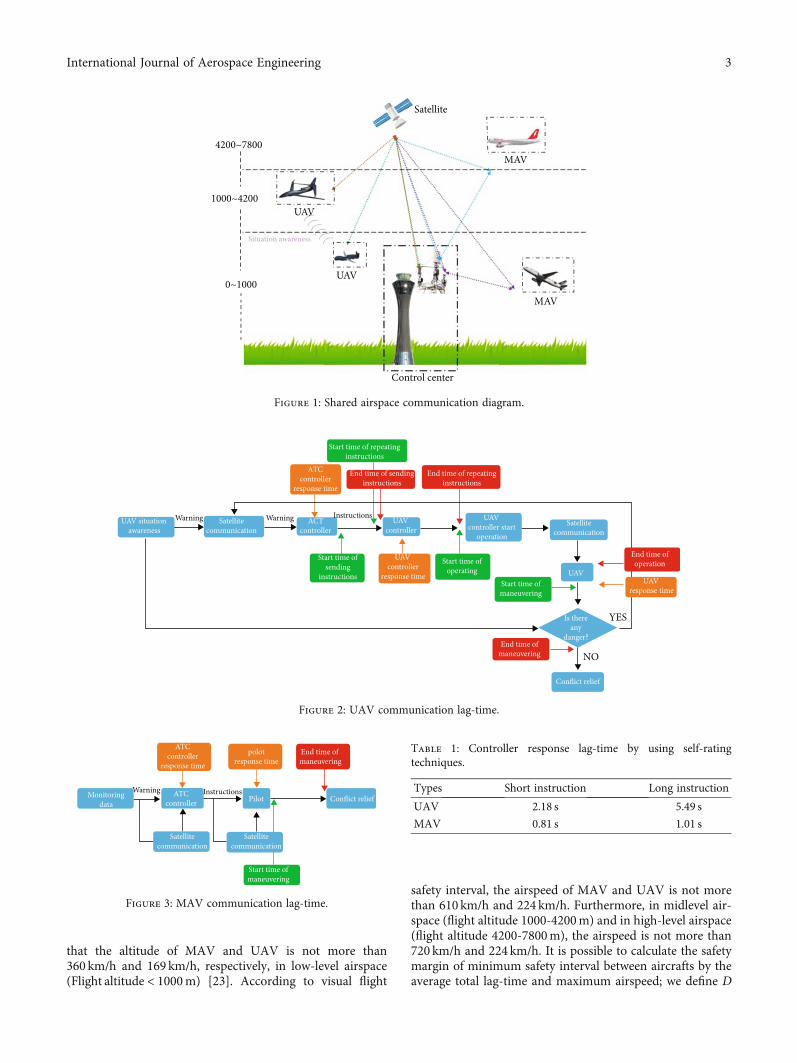
2.2. Communication Lag-Time. To note that, UAVs in ourpaper must be capable of two-way communication, such asutilizing microwave signals for satellite communications(as shown in Figure 1). The situation awareness data wire-lessly transferred to UAVs must transit shipment by satellite.Compared with the speed of communication of MAVs,undoubtedly, the former produces a more prolonged timelag than the latter (MAVs are able to establish direct com-munication through a very high-frequency signal with theground station). Similarly, the ATC instruction of theUAV controller also requires satellite data link to reach thefront end of UAV’s receiver, whereas this bidirectional com-munication process is only a part of the total lag-time.
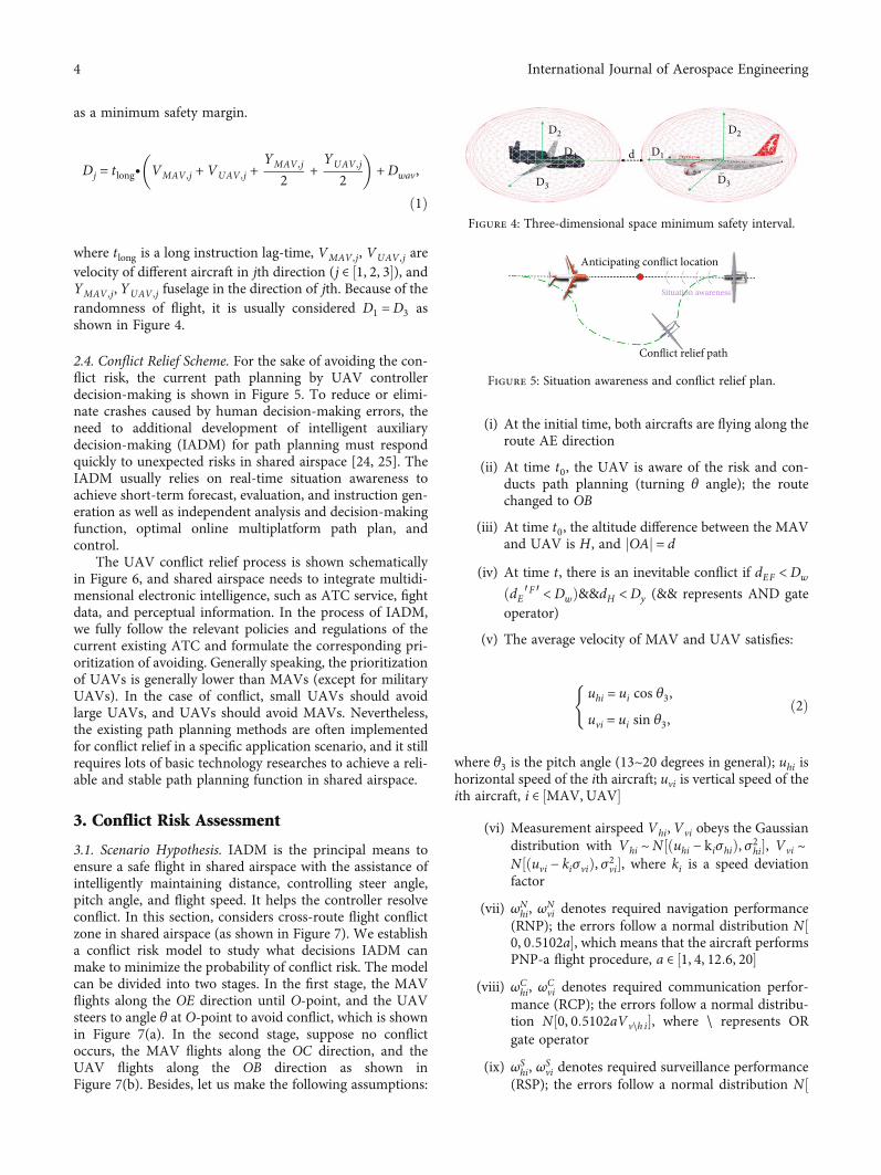
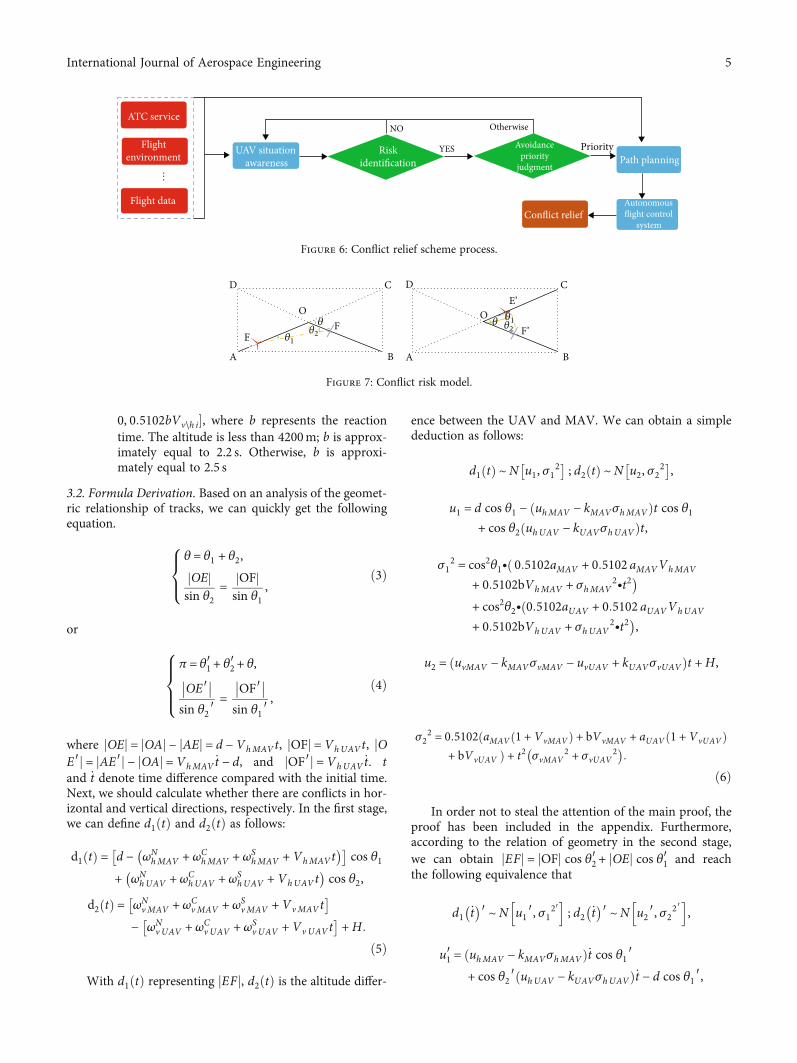
Response lag-time is a time interval before human ormachine is able to perform a response operation. Maneuverlag-time is defined as the time interval between aircraft(UAVs or MAVs) executing maneuvers and accomplishingthe maneuver. As presented in the schematic illustration(Figure 2), other factors contain the ATC controllerresponse lag-time, UAV controller response lag-time, UAVresponse lag-time, repeat instruction lag-time, and maneu-ver lag-time. On the contrary, the MAVs only include one-way link transmission lag-time, ATC controller responselag-time, pilot response lag-time, and maneuver lag-time(Figure 3). Additionally, the pilot operates the aircraftdirectly in case of emergency; there is only maneuver lag-time. Obviously, the lag-time of UAVs is much higher thanMAVs in summary.
The communication between UAVs using a methodbased on literature [21] used smart agents; this requires alot of training and does not seem feasible in a complex air-space. Self-rating techniques refer to each subject which pro-vides a subjective measure of his/her lag-time based on arating scale after task execution [22]. This paper makes fulluse of self-rating techniques to assess controller responselag-time. It means the machine lag-time and maneuver lag-time are acquired by a transducer. At the same time, adetailed summary of the total lag-time is made through vastamounts of data from China’s Southwest Air Traffic ControlBureau. We collect and assess the average total lag-time gen-erated by short instruction (instruction word length 32 bits)and long instruction (instruction word length 64 bits), pleasesee Table 1 for further details. More importantly, only longinstruction is considered in this paper because it can makethe conflict risk assessment model have an additional safetymargin.
2.3. Minimum Safety Interval. It was demonstrated inEUROCONTROL Airspace management (ASM) of studies
2 International Journal of Aerospace Engineering
that the altitude of MAV and UAV is not more than360 km/h and 169 km/h, respectively, in low-level airspace(Flight altitude < 1000m) [23]. According to visual flight
safety interval, the airspeed of MAV and UAV is not morethan 610 km/h and 224 km/h. Furthermore, in midlevel air-space (flight altitude 1000-4200m) and in high-level airspace(flight altitude 4200-7800m), the airspeed is not more than720 km/h and 224 km/h. It is possible to calculate the safetymargin of minimum safety interval between aircrafts by theaverage total lag-time and maximum airspeed; we define D
1000~4200
4200~7800
0~1000
Situation awareness
UAV
Satellite
MAV
UAV
Control center
MAV
Figure 1: Shared airspace communication diagram.
Start time of repeatinginstructions
ATCcontroller
response time
End time of sendinginstructions
End time of repeatinginstructions
UAV situationawareness
Satellitecommunication
ACTcontroller
UAVcontroller
UAVcontroller start
operation
Satellitecommunication
End time ofoperation
UAVresponse time
Start time ofsending
instructions
UAVcontroller
response time
Start time ofoperating
End time ofmaneuvering
Start time ofmaneuvering
UAV
Is thereany
danger?
Conflict relief
Warning Warning Instructions
YES
NO
Figure 2: UAV communication lag-time.
ATCcontroller
response time
polotresponse time
End time of maneuvering
Conflict reliefPilot
Satellitecommunication
Satellitecommunication
Monitoringdata
ATCcontroller
Start time ofmaneuvering
Warning Instructions
Figure 3: MAV communication lag-time.
Table 1: Controller response lag-time by using self-ratingtechniques.
Types Short instruction Long instruction
UAV 2.18 s 5.49 s
MAV 0.81 s 1.01 s
3International Journal of Aerospace Engineering
as a minimum safety margin.
Dj = tlong∙ VMAV ,j + VUAV ,j +YMAV ,j
2 +YUAV ,j
2
� �+Dwav,
ð1Þ
where tlong is a long instruction lag-time, VMAV ,j, VUAV ,j arevelocity of different aircraft in jth direction (j ∈ ½1, 2, 3�), andYMAV ,j, YUAV ,j fuselage in the direction of jth. Because of therandomness of flight, it is usually considered D1 =D3 asshown in Figure 4.
2.4. Conflict Relief Scheme. For the sake of avoiding the con-flict risk, the current path planning by UAV controllerdecision-making is shown in Figure 5. To reduce or elimi-nate crashes caused by human decision-making errors, theneed to additional development of intelligent auxiliarydecision-making (IADM) for path planning must respondquickly to unexpected risks in shared airspace [24, 25]. TheIADM usually relies on real-time situation awareness toachieve short-term forecast, evaluation, and instruction gen-eration as well as independent analysis and decision-makingfunction, optimal online multiplatform path plan, andcontrol.
The UAV conflict relief process is shown schematicallyin Figure 6, and shared airspace needs to integrate multidi-mensional electronic intelligence, such as ATC service, fightdata, and perceptual information. In the process of IADM,we fully follow the relevant policies and regulations of thecurrent existing ATC and formulate the corresponding pri-oritization of avoiding. Generally speaking, the prioritizationof UAVs is generally lower than MAVs (except for militaryUAVs). In the case of conflict, small UAVs should avoidlarge UAVs, and UAVs should avoid MAVs. Nevertheless,the existing path planning methods are often implementedfor conflict relief in a specific application scenario, and it stillrequires lots of basic technology researches to achieve a reli-able and stable path planning function in shared airspace.
3. Conflict Risk Assessment
3.1. Scenario Hypothesis. IADM is the principal means toensure a safe flight in shared airspace with the assistance ofintelligently maintaining distance, controlling steer angle,pitch angle, and flight speed. It helps the controller resolveconflict. In this section, considers cross-route flight conflictzone in shared airspace (as shown in Figure 7). We establisha conflict risk model to study what decisions IADM canmake to minimize the probability of conflict risk. The modelcan be divided into two stages. In the first stage, the MAVflights along the OE direction until O-point, and the UAVsteers to angle θ at O-point to avoid conflict, which is shownin Figure 7(a). In the second stage, suppose no conflictoccurs, the MAV flights along the OC direction, and theUAV flights along the OB direction as shown inFigure 7(b). Besides, let us make the following assumptions:
(i) At the initial time, both aircrafts are flying along theroute AE direction
(ii) At time t0, the UAV is aware of the risk and con-ducts path planning (turning θ angle); the routechanged to OB
(iii) At time t0, the altitude difference between the MAVand UAV is H, and jOAj = d
(iv) At time t, there is an inevitable conflict if dEF <Dw
ðdE′F ′ <DwÞ&&dH <Dy (&& represents AND gateoperator)
(v) The average velocity of MAV and UAV satisfies:
uhi = ui cos θ3,uvi = ui sin θ3,
(ð2Þ
where θ3 is the pitch angle (13~20 degrees in general); uhi ishorizontal speed of the ith aircraft; uvi is vertical speed of theith aircraft, i ∈ ½MAV, UAV�
(vi) Measurement airspeed Vhi, Vvi obeys the Gaussiandistribution with Vhi ~N½ðuhi − kiσhiÞ, σ2
hi�, Vvi ~N½ðuvi − kiσviÞ, σ2vi�, where ki is a speed deviationfactor
(vii) ωNhi, ω
Nvi denotes required navigation performance
(RNP); the errors follow a normal distribution N½0, 0:5102a�, which means that the aircraft performsPNP-a flight procedure, a ∈ ½1, 4, 12:6, 20�
(viii) ωChi, ω
Cvi denotes required communication perfor-
mance (RCP); the errors follow a normal distribu-tion N½0, 0:5102aVv\h i�, where \ represents ORgate operator
(ix) ωShi, ω
Svi denotes required surveillance performance
(RSP); the errors follow a normal distribution N½
d D1
D2
D3D3
D4
D2
Figure 4: Three-dimensional space minimum safety interval.
Anticipating conflict location
Conflict relief path
Situation awareness
Figure 5: Situation awareness and conflict relief plan.
4 International Journal of Aerospace Engineering
0, 0:5102bVv\h i�, where b represents the reactiontime. The altitude is less than 4200m; b is approx-imately equal to 2.2 s. Otherwise, b is approxi-mately equal to 2.5 s
3.2. Formula Derivation. Based on an analysis of the geomet-ric relationship of tracks, we can quickly get the followingequation.
θ = θ1 + θ2,OEj j
sin θ2= OFj jsin θ1
,
8><>: ð3Þ
or
π = θ1′ + θ2′ + θ,OE′�� ��sin θ2 ′
= OF′�� ��sin θ1 ′
,
8>><>>:
ð4Þ
where jOEj = jOAj − jAEj = d − VhMAVt, jOFj =VhUAVt, jOE′j = jAE′j − jOAj = VhMAV
_t − d, and jOF′j =VhUAV_t. t
and _t denote time difference compared with the initial time.Next, we should calculate whether there are conflicts in hor-izontal and vertical directions, respectively. In the first stage,we can define d1ðtÞ and d2ðtÞ as follows:
d1 tð Þ = d − ωNhMAV + ωC
hMAV + ωShMAV +VhMAVt
� �� �cos θ1
+ ωNhUAV + ωC
hUAV + ωShUAV +VhUAVt
� �cos θ2,
d2 tð Þ = ωNvMAV + ωC
vMAV + ωSvMAV +VvMAVt
� �− ωN
vUAV + ωCv UAV + ωS
v UAV +VvUAVt� �
+H:
ð5Þ
With d1ðtÞ representing jEFj, d2ðtÞ is the altitude differ-
ence between the UAV and MAV. We can obtain a simplededuction as follows:
d1 tð Þ ~N u1, σ12� �
; d2 tð Þ ~N u2, σ22� �,
u1 = d cos θ1 − uhMAV − kMAVσhMAVð Þt cos θ1+ cos θ2 uhUAV − kUAVσhUAVð Þt,
σ12 = cos2θ1∙ 0:5102aMAV + 0:5102 aMAVVhMAVð
+ 0:5102bVhMAV + σhMAV2∙t2
�+ cos2θ2∙ 0:5102aUAV + 0:5102 aUAVVhUAVð+ 0:5102bVhUAV + σhUAV
2∙t2�,
u2 = uvMAV − kMAVσvMAV − uvUAV + kUAVσvUAVð Þt +H,
σ22 = 0:5102 aMAV 1 + VvMAVð Þ + bVvMAV + aUAV 1 +VvUAVð Þð
+ bVvUAV Þ + t2 σvMAV2 + σvUAV
2� �:
ð6Þ
In order not to steal the attention of the main proof, theproof has been included in the appendix. Furthermore,according to the relation of geometry in the second stage,we can obtain jEFj = jOFj cos θ2′ + jOEj cos θ1′ and reachthe following equivalence that
d1 _t� �′ ~N u1 ′, σ12′
h i; d2 _t
� �′ ~N u2 ′, σ22′
h i,
u1′ = uhMAV − kMAVσhMAVð Þ_t cos θ1 ′+ cos θ2 ′ uhUAV − kUAVσhUAVð Þ_t − d cos θ1 ′,
ATC service
Flightenvironment
Flight data
UAV situationawareness
Riskidentification
Avoidancepriority
judgment
Conflict relief
Path planning
Autonomousflight control
system
YES
NO Otherwise
Priority
...
Figure 6: Conflict relief scheme process.
AA B B
C CDD
EF
O O𝜃 𝜃
𝜃1
𝜃1𝜃2
𝜃2
E’
F’
Figure 7: Conflict risk model.
5International Journal of Aerospace Engineering
Table2:Experim
entparameters.
Airspace
PSP
PNP
MAVho
rizontal
airspeed
variance
(m2 )
UAVho
rizontal
airspeed
variance
(m2 )
MAVvertical
airspeed
variance
(m2 )
UAVvertical
airspeed
variance
(m2 )
MAV
airspeed
deviation
factor
UAV
airspeed
deviation
factor
Maxim
umairspeed
ofMAV(km/h)
Maxim
umairspeed
ofUAV(km/h)
Horizon
tal
safety
margin
DH(m
)
Vertical
safety
marginDv
(m)
Low-
level
2.2
14.7
31.71
10.675
1360
169
1:1204
×10
3353.78
Midlevel
2.2
14.7
31.71
10.675
1610
224
1:5846
×10
3567.78
High-
level
2.5
4.1
6.12
4.1
2.31
1.33
0.675
1720
224
1:7521
×10
3569.84
6 International Journal of Aerospace Engineering
σ12′ = cos2θ1 ′∙ 0:5102aMAV + 0:5102 aMAVVhMAVð
+ 0:5102bVhMAV + σhMAV2∙_t2
+ cos2θ2 ′∙ 0:5102aUAV + 0:5102 aUAVVhUAVð+ 0:5102bVhUAV + σhUAV
2∙_t2,
u2′ = uvMAV − kMAVσvMAV − uvUAV + kUAVσvUAVð Þ_t +H,σ2
2′ = 0:5102 aMAV 1 +VvMAVð Þ + bVvMAVð+ aUAV 1 +VvUAVð Þ + bVvUAV Þ+ _t2 σvMAV
2 + σvUAV2� �:
ð7Þ
The proof process is similar and should be no longerrepeated here.
Furthermore, let f d1ðxÞ and f d2ðxÞ be the probabilitydensity function (PDF) of the horizontal and vertical dis-tance between aircraft the MAV and UAV:
f d1 xð Þ = 1ffiffiffiffiffiffi2π
pσ1
e− x−u1ð Þ2/2σ12 ,
f d2 xð Þ = 1ffiffiffiffiffiffi2π
pσ2
e− x−u2ð Þ2/2σ22 :ð8Þ
Horizontal conflict and vertical conflict can be regarded
as two independent events. We assume that PhðtÞ, PvðtÞ arethe conflict probabilities in horizontal and vertical direc-tions, respectively.
Ph,v tð Þ = Ph tð Þ∙Pv tð Þ: ð9Þ
Simultaneity, Dj is closely related to conflict risk analysis.For instance, if the interval between two aircrafts is reducedto a certain value, the conflict may be unavoidable.
Ph tð Þ = P d1j j ≤D1ð Þ =ðD1
−D1
1ffiffiffiffiffiffi2π
pσ1
e− x−u1ð Þ2/2σ12dx, ð10Þ
Pv tð Þ = P d2j j ≤D2ð Þ =ðD2
−D2
1ffiffiffiffiffiffi2π
pσ2
e− x−u2ð Þ2/2σ22dx: ð11Þ
Integrating Equations (10) and (11), we can obtainPh,vðtÞ from Equation (9). Next, the complexity of thealgorithm is analyzed, letting the number of executions TðnÞ be a function of the problem scale n. Represent thechange of TðnÞ with n and determine the order of magni-tude of TðnÞ. Secondly, the growth rate of algorithm exe-cution time is f ðnÞ, TðnÞ =Oð f ðnÞÞ. The algorithmcomplexity calculation rule replaces all additive constantsin run time with constant 1; meanwhile, keep the highestorder items. Time complexity according to sequential
Time/s
(a) (b) (c)
(d) (e) (f)
Perc
enta
ge (%
)
0
10
10
20
20
30
30
40
40
50
50
60
70
80
90
100
0Time/s
Perc
enta
ge (%
)
0
10
20
30
40
50
60
70
80
90
100
10 20 30 40 500
Time/s
Perc
enta
ge (%
)
0
0.5
20
30
40
50
60
70
80
90
100
0 5 10 15 20 25 30 35 40 45 50
Time/s
Perc
enta
ge (%
)
0
10
20
30
40
50
60
70
80
90
100
10 20 30 40 500Time/s
Perc
enta
ge (%
)
0
10
20
30
40
50
60
70
80
90
100
10 20 30 40 500
Perc
enta
ge (%
)
0
10
20
30
40
50
60
70
80
90
100
10 20 30 40 500Time/s
1.5Km
1.7Km
1.9Km
2.1Km
2.3Km2.5Km
2.7Km
2.9Km
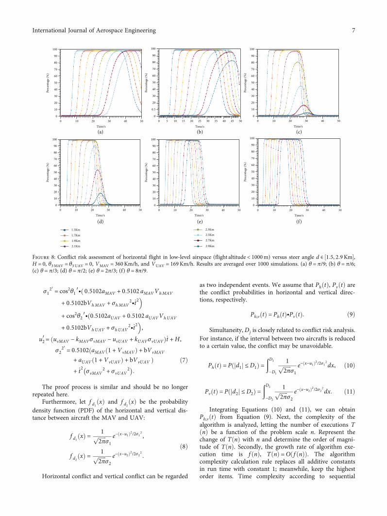
Figure 8: Conflict risk assessment of horizontal flight in low-level airspace (flight altitude < 1000m) versus steer angle d ∈ ½1:5, 2:9Km�,H = 0, θ3MAV = θ3UAV = 0, VMAV = 360Km/h, and VUAV = 169Km/h. Results are averaged over 1000 simulations. (a) θ = π/9; (b) θ = π/6;(c) θ = π/3; (d) θ = π/2; (e) θ = 2π/3; (f) θ = 8π/9:
7International Journal of Aerospace Engineering
structure, f ðnÞ = 4. It has no highest order term at all, sothe time complexity of this algorithm is Oð1Þ.
4. Experiments
In this section, we describe our experiments. All scenarios areimplemented in MATLAB and run on an I5-4200U @1.60GHz Intel Core with 8GB RAM. Statistical measures areused to study the simulated results; each result is averaged over1000 simulations. For our experiments, unbolted curves in theillustration indicate conflict probability < 10ð−7Þ. We need toplace more emphasis on parameters that minimize conflictprobability in various scenarios. It provides a theoretical basisfor IDAM to avoid risks.
4.1. Simulation Parameters. Assume that the MAV is Boe-ing 747-400; the scale is about 70:6m × 60:4m × 19:4m.The UAV-“Shen Diao” scale is about 42m × 29:6m ×4:5m. Suppose there is a long instruction lag-time; theminimum safety margin is obtained by Equation (1).The so-called RNP-a flight procedure referring to 95%of total flight time must not deviate from a mile oneither side of the route centerline. In low-level and mid-level airspace, they fly in compliance with the PNP-1procedure; the response time of monitoring equipmentis 2.2 s in RSP.
Meanwhile, in high-level airspace, flying follows thePNP-4.1 procedure; the response time of monitoring equip-ment is 2.5 s. The aircraft speed is measured by the speedsensor and then transmitted by ADS-B; the measurementspeed variance is also affected by airspace altitude as shownfrom data in Table 2 for more detail parameters. In the next,four works are examined to assess conflict risk based on dif-ferent situations and the flight environment.
4.2. Conflict Risk Assessment of Horizontal Flight in Low-LevelAirspace. The relationship between initial distance d andconflict risk in low-level airspace (flight altitude < 1000m) ispresented below. For private parameters, H = 0, θ3MAV =θ3UAV = 0, VMAV = 360Km/h, VUAV = 169Km/h. The valuerange of d ∈ ½1:5Km, 2:9Km�; different steer angles θ wereused as reference experiments. 1000Monte Carlo runs are per-formed, and the result is averaged over all runs. As shown inFigure 8, we can easily get that conflict onset is delayed withincreasing d. Meanwhile, it is interesting to see that conflictrisk decreases as d increases in certain θ steer angle. This trendis because the aircraft maneuver is too late to respond in longinstruction lag-time when d is small enough. Another reasonis that a narrow steer angle also increases the chance of conflictrisk. To further explore the relationship between steer angle θand conflict risk in the low-level airspace, we pick a broadervalue for d, d ∈ ½1Km, 3:5Km�. To illustrate the preceding
Time/s
(a) (b) (c)
(d) (e) (f)
Perc
enta
ge (%
)
0
10
20
30
40
50
60
70
80
90
100
Time/s
Perc
enta
ge (%
)
0
10
20
30
40
50
60
70
80
90
100
Time/s
Perc
enta
ge (%
)
0
0.5
20
30
40
50
60
70
80
90
100
Time/s
Perc
enta
ge (%
)
0
10
20
30
40
50
60
70
80
90
100
Time/s
Perc
enta
ge (%
)
0
10
20
30
40
50
60
70
80
90
100
Perc
enta
ge (%
)
0
10
20
30
40
50
60
70
80
90
100
Time/s
pi/9
2pi/9
3pi/9
4pi/9
5pi/9
6pi/9
7pi/9
8pi/9
0 10 20 30 40 50 60 70 80 0 10 20 30 40 50 60 70 80 0 10 20 30 40 50 60 70 80
0 10 20 30 40 50 60 70 800 10 20 30 40 50 60 70 80 0 10 20 30 40 50 60 70 80
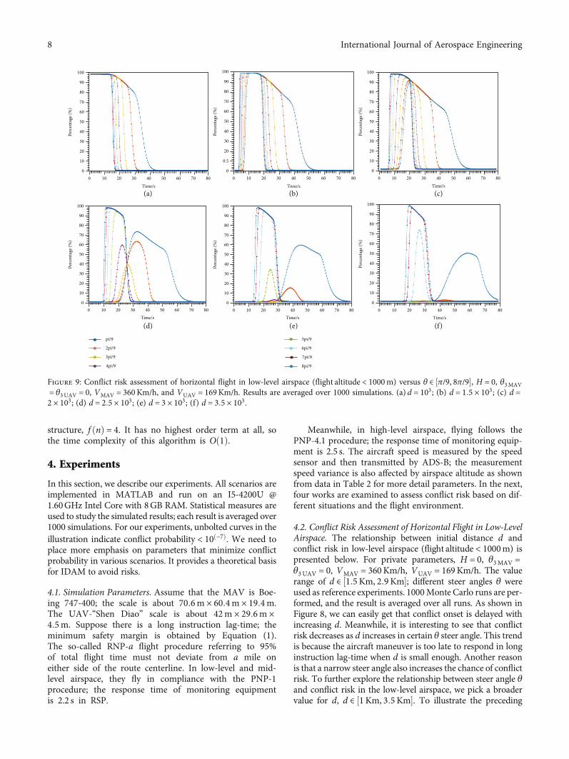
Figure 9: Conflict risk assessment of horizontal flight in low-level airspace (flight altitude < 1000m) versus θ ∈ ½π/9, 8π/9�, H = 0, θ3MAV= θ3UAV = 0, VMAV = 360Km/h, and VUAV = 169Km/h. Results are averaged over 1000 simulations. (a) d = 103; (b) d = 1:5 × 10³; (c) d =2 × 10³; (d) d = 2:5 × 10³; (e) d = 3 × 10³; (f) d = 3:5 × 10³.
8 International Journal of Aerospace Engineering
analysis with experimental results as shown in Figure 9, the steerangle θ = 3π/9 is s more sensitive to changes in d, and conflictrisk is minimized in this experiment. On the contrary, the steerangle θ = 8π/9 is not sensitive to the change in d. Since the speedof MAVs does not differ significantly from UAVs in low-levelairspace, the second conflict risk may occur at a specific d. Sec-ondary conflict risk should also be considered in IDAM design.
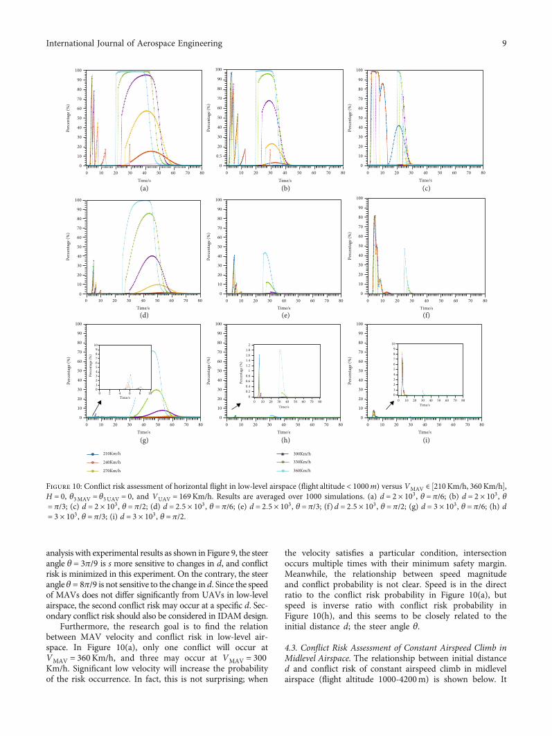
Furthermore, the research goal is to find the relationbetween MAV velocity and conflict risk in low-level air-space. In Figure 10(a), only one conflict will occur atVMAV = 360Km/h, and three may occur at VMAV = 300Km/h. Significant low velocity will increase the probabilityof the risk occurrence. In fact, this is not surprising; when
the velocity satisfies a particular condition, intersectionoccurs multiple times with their minimum safety margin.Meanwhile, the relationship between speed magnitudeand conflict probability is not clear. Speed is in the directratio to the conflict risk probability in Figure 10(a), butspeed is inverse ratio with conflict risk probability inFigure 10(h), and this seems to be closely related to theinitial distance d; the steer angle θ.
4.3. Conflict Risk Assessment of Constant Airspeed Climb inMidlevel Airspace. The relationship between initial distanced and conflict risk of constant airspeed climb in midlevelairspace (flight altitude 1000-4200m) is shown below. It
Time/s
(a) (b) (c)
(d) (e) (f)
(g) (h) (i)
Perc
enta
ge (%
)
0
10
20
30
40
50
60
70
80
90
100
Perc
enta
ge (%
)
0
10
20
30
40
50
60
70
80
90
100
Time/s
Perc
enta
ge (%
)
0
0.5
20
30
40
50
60
70
80
90
100
0 10 20 30 40 50 60 70 80 0 10 20 30 40 50 60 70 80 0 10 20 30 40 50 60 70 80Time/s
Time/s
Perc
enta
ge (%
)
0
10
20
30
40
50
60
70
80
90
100
0 10 20 30 40 50 60 70 80
Perc
enta
ge (%
)
0
10
20
30
40
50
60
70
80
90
100
Time/s0 10 20 30 40 50 60 70 80
Perc
enta
ge (%
)
0
10
20
30
40
50
60
70
80
90
100
Time/s0 10 20 30 40 50 60 70 80
Perc
enta
ge (%
)
0
10
20
30
40
50
60
70
80
90
100
Time/s0 10 20 30 40 50 60 70 80
Perc
enta
ge (%
)
0
10
20
30
40
50
60
70
80
90
100
Time/s0 10 20 30 40 50 60 70 80
Time/s
Perc
enta
ge (%
)
0
10
20
30
40
50
60
70
80
90
100
0 10 20 30 40 50 60 70 80
0 10 20 30 40 50 60 70 800 10 20 30 40 50 60 70 80
0123456789
10
0123456789
10
0 2 4 6 8 10Time/s
Time/s Time/s
00.20.40.60.8
11.21.41.61.8
2
Perc
enta
ge (%
)
Perc
enta
ge (%
)
210Km/h
240Km/h
270Km/h
300Km/h
330Km/h
360Km/h
Figure 10: Conflict risk assessment of horizontal flight in low-level airspace (flight altitude < 1000m) versus VMAV ∈ ½210Km/h, 360Km/h�,H = 0, θ3MAV = θ3UAV = 0, and VUAV = 169Km/h. Results are averaged over 1000 simulations. (a) d = 2 × 10³, θ = π/6; (b) d = 2 × 10³, θ= π/3; (c) d = 2 × 10³, θ = π/2; (d) d = 2:5 × 10³, θ = π/6; (e) d = 2:5 × 10³, θ = π/3; (f) d = 2:5 × 10³, θ = π/2; (g) d = 3 × 10³, θ = π/6; (h) d= 3 × 10³, θ = π/3; (i) d = 3 × 10³, θ = π/2.
9International Journal of Aerospace Engineering
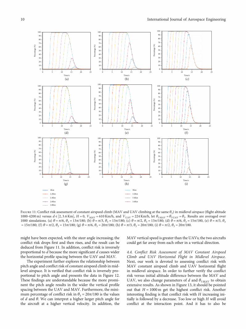
might have been expected, with the steer angle increasing; theconflict risk drops first and then rises, and the result can bededuced from Figure 11. In addition, conflict risk is inverselyproportional to d because the more significant d causes widerthe horizontal profile spacing between the UAV and MAV.
The experiment further explores the relationship betweenpitch angle and conflict risk of constant airspeed climb inmid-level airspace. It is verified that conflict risk is inversely pro-portional to pitch angle and presents the data in Figure 12.These findings are understandable because the more promi-nent the pitch angle results in the wider the vertical profilespacing between the UAV and MAV. Furthermore, the mini-mum percentage of conflict risk in θ3 = 20π/180 is the valuesof d and θ. We can interpret a higher larger pitch angle forthe aircraft at a higher vertical velocity. In addition, the
MAV vertical speed is greater than the UAVs; the two aircraftscould get far away from each other in a vertical direction.
4.4. Conflict Risk Assessment of MAV Constant AirspeedClimb and UAV Horizontal Flight in Midlevel Airspace.Next, our work is devoted to assessing conflict risk withMAV constant airspeed climb and UAV horizontal flightin midlevel airspace. In order to further verify the conflictrisk versus initial altitude difference between the MAV andUAV, we also change parameters of d and θ3MAV to obtainextensive results. As shown in Figure 13, it should be pointedout that H = 1000m get the highest conflict risk. Anotherinteresting finding is that conflict risk with H increasing ini-tially is followed by a decrease. Too low or high H will avoidconflict at the interaction point. And it has to also be
0 5 10 15 20 25Time/s
(a) (b) (c)
(d) (e) (f)
(g) (h) (i)
100
90
80
70
60
50
40
30
20
10
0
Perc
enta
ge (%
)
0 5 10 15 20 25Time/s
100
90
80
70
60
50
40
30
20
10
0
Perc
enta
ge (%
)
0 5 10 15 20 25Time/s
100
90
80
70
60
50
40
30
20
10
0
Perc
enta
ge (%
)
0 5 10 15 20 25Time/s
100
90
80
70
60
50
40
30
20
10
0
Perc
enta
ge (%
)
0 5 10 15 20 25Time/s
100
90
80
70
60
50
40
30
20
10
0
Perc
enta
ge (%
)
0 5 10 15 20 25Time/s
100
90
80
70
60
50
40
30
20
10
0
Perc
enta
ge (%
)
0 5 10 15 20 25Time/s
100
90
80
70
60
50
40
30
20
10
0
Perc
enta
ge (%
)
0 5 10 15 20 25Time/s
100
90
80
70
60
50
40
30
20
10
Perc
enta
ge (%
)
0 5 10 15 20 25Time/s
100
90
80
70
60
50
40
30
20
10
0 0
Perc
enta
ge (%
)
2Km
2.2Km
2.4Km
2.6Km2.8Km
3Km
3.2Km
3.4Km
3.6Km
Figure 11: Conflict risk assessment of constant airspeed climb (MAV and UAV climbing at the same θ3) in midlevel airspace (flight altitude1000-4200m) versus d ∈ ½2, 3:6Km�, H = 0, VMAV = 610Km/h, and VUAV = 224Km/h, let θ3MAV = θ3UAV = θ3. Results are averaged over1000 simulations. (a) θ = π/6, θ3 = 13π/180; (b) θ = π/3, θ3 = 13π/180; (c) θ = π/2, θ3 = 13π/180; (d) θ = π/6, θ3 = 15π/180, (e) θ = π/3, θ3= 15π/180; (f) θ = π/2, θ3 = 15π/180; (g) θ = π/6, θ3 = 20π/180; (h) θ = π/3, θ3 = 20π/180; (i) θ = π/2, θ3 = 20π/180.
10 International Journal of Aerospace Engineering
0 5 10 15 20 25Time/s
(a) (b) (c)
(d) (e) (f)
100
90
80
70
60
50
40
30
20
10
0
Perc
enta
ge (%
)
0 5 10 15 20 25Time/s
100
90
80
70
60
50
40
30
20
10
0
Perc
enta
ge (%
)
0 5 10 15 20 25Time/s
100
90
80
70
60
50
40
30
20
10
0
Perc
enta
ge (%
)
Time/s
100
90
80
70
60
50
40
30
20
10
Perc
enta
ge (%
)
Perc
enta
ge (%
)
Time/s
100
90
80
70
60
50
40
30
20
10
0
Perc
enta
ge (%
)
00
0.5
1
1.5
2
2.5
5 10 15 20 25Time/s
Time/s
100
90
80
70
60
50
40
30
20
10
0 5 10 15 20 250
0 5 10 15 20 25 0 5 10 15 20 250
Perc
enta
ge (%
)
00
2
4
6
8
14
12
10
5 10 15 20 25Time/s
Perc
enta
ge (%
)
13⁎pi/180
14⁎pi/180
15⁎pi/180
16⁎pi/180
17⁎pi/180
18⁎pi/180
19⁎pi/180
20⁎pi/180
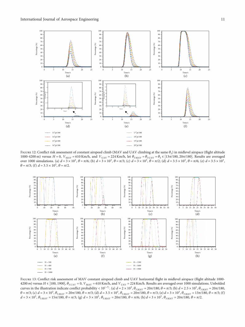
Figure 12: Conflict risk assessment of constant airspeed climb (MAV and UAV climbing at the same θ3) in midlevel airspace (flight altitude1000-4200m) versus H = 0, VMAV = 610Km/h, and VUAV = 224Km/h, let θ3MAV = θ3UAV = θ3 ∈ ½13π/180, 20π/180�. Results are averagedover 1000 simulations. (a) d = 3 × 10³, θ = π/6; (b) d = 3 × 10³, θ = π/3; (c) d = 3 × 10³, θ = π/2; (d) d = 3:5 × 10³, θ = π/6; (e) d = 3:5 × 10³,θ = π/3; (f) d = 3:5 × 10³, θ = π/2.
Time/s(a) (b) (c) (d)
(e) (f) (g) (h)
100908070605040302010
0
Perc
enta
ge (%
)
Time/s
100908070605040302010
0
Perc
enta
ge (%
)
0 5 10 15 20 25 30 35 40 45 50Time/s
100908070605040302010
0
Perc
enta
ge (%
)
0 5 10 15 20 25 30 35 40 45 50Time/s
100908070605040302010
0
Perc
enta
ge (%
)
0 5 10 15 20 25 30 35 40 45 50Time/s
100908070605040302010
0
Perc
enta
ge (%
)
0 5 10 15 20 25 30 35 40 45 50Time/s
100908070605040302010
Perc
enta
ge (%
)
0 5 10 15 20 25 30 35 40 45 50Time/s
100908070605040302010
Perc
enta
ge (%
)
0 5 10 15 20 25 30 35 40 45 50Time/s
100908070605040302010
0 0 0
Perc
enta
ge (%
)
H = 100H = 400H = 700H = 1000
H = 1300H = 1600H = 1900
0 10 20 30 40 50 0 10 20 30 40 50
Figure 13: Conflict risk assessment of MAV constant airspeed climb and UAV horizontal flight in midlevel airspace (flight altitude 1000-4200m) versus H ∈ ½100, 1900�, θ3UAV = 0, VMAV = 610Km/h, and VUAV = 224Km/h. Results are averaged over 1000 simulations. Unboldedcurves in the illustration indicate conflict probability < 10ð−7Þ. (a) d = 2 × 10³, θ3MAV = 20π/180, θ = π/3; (b) d = 2:5 × 10³, θ3MAV = 20π/180,θ = π/3; (c) d = 3 × 10³, θ3MAV = 20π/180, θ = π/3; (d) d = 3:5 × 10³, θ3MAV = 20π/180, θ = π/3; (e) d = 3 × 10³, θ3MAV = 13π/180, θ = π/3; (f)d = 3 × 10³, θ3MAV = 15π/180, θ = π/3; (g) d = 3 × 10³, θ3MAV = 20π/180, θ = π/6; (h) d = 3 × 10³, θ3MAV = 20π/180, θ = π/2.
11International Journal of Aerospace Engineering
mentioned that conflict risk rises rapidly with d or θ3MAVincreasing, by comparison with curve trend. The major reasonis increasing d causes a backward shift in interaction time.
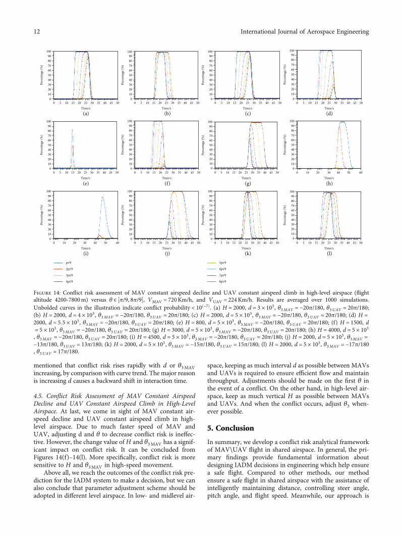
4.5. Conflict Risk Assessment of MAV Constant AirspeedDecline and UAV Constant Airspeed Climb in High-LevelAirspace. At last, we come in sight of MAV constant air-speed decline and UAV constant airspeed climb in high-level airspace. Due to much faster speed of MAV andUAV, adjusting d and θ to decrease conflict risk is ineffec-tive. However, the change value of H and θ3MAV has a signif-icant impact on conflict risk. It can be concluded fromFigures 14(f)–14(l). More specifically, conflict risk is moresensitive to H and θ3MAV in high-speed movement.
Above all, we reach the outcomes of the conflict risk pre-diction for the IADM system to make a decision, but we canalso conclude that parameter adjustment scheme should beadopted in different level airspace. In low- and midlevel air-
space, keeping as much interval d as possible between MAVsand UAVs is required to ensure efficient flow and maintainthroughput. Adjustments should be made on the first θ inthe event of a conflict. On the other hand, in high-level air-space, keep as much vertical H as possible between MAVsand UAVs. And when the conflict occurs, adjust θ3 when-ever possible.
5. Conclusion
In summary, we develop a conflict risk analytical frameworkof MAV\UAV flight in shared airspace. In general, the pri-mary findings provide fundamental information aboutdesigning IADM decisions in engineering which help ensurea safe flight. Compared to other methods, our methodensure a safe flight in shared airspace with the assistance ofintelligently maintaining distance, controlling steer angle,pitch angle, and flight speed. Meanwhile, our approach is
0 5 10 15 20 25 30 35 40 45 50Time/s
(a) (b) (c) (d)
(e) (f) (g) (h)
(i) (j) (k) (l)
100908070605040302010
0
Perc
enta
ge (%
)
Time/s
100
0 5 10 15 20 25 30 35 40 45 50
908070605040302010
0
Perc
enta
ge (%
)
100
0 5 10 15 20 25 30 35 40 45 50Time/s
908070605040302010
0
Perc
enta
ge (%
)
100
0 5 10 15 20 25 30 35 40 45 50Time/s
908070605040302010
0
Perc
enta
ge (%
)
0 5 10 15 20 25 30 35 40 45 50Time/s
100908070605040302010
0
Perc
enta
ge (%
)
0 5 10 15 20 25 30 35 40 45 50Time/s
100908070605040302010
0
Perc
enta
ge (%
)
0 5 10 15 20 25 30 35 40 45 50Time/s
100908070605040302010
0
Perc
enta
ge (%
)
Time/s
100908070605040302010
0
Perc
enta
ge (%
)
Time/s
100908070605040302010
0
Perc
enta
ge (%
)
0 5 10 15 20 25 30 35 40 45 50Time/s
0 5 10 15 20 25 30 35 40 45 50Time/s
0 5 10 15 20 25 30 35 40 45 50Time/s
0 10 20 30 40 50 60
100908070605040302010
0
Perc
enta
ge (%
)
100908070605040302010
0
Perc
enta
ge (%
)
100908070605040302010
0
Perc
enta
ge (%
)
pi/9 5pi/9
6pi/9
7pi/9
8pi/9
2pi/9
3pi/9
4pi/9
0 10 20 30 40 50 60
Figure 14: Conflict risk assessment of MAV constant airspeed decline and UAV constant airspeed climb in high-level airspace (flightaltitude 4200-7800m) versus θ ∈ ½π/9, 8π/9�, VMAV = 720Km/h, and VUAV = 224Km/h. Results are averaged over 1000 simulations.Unbolded curves in the illustration indicate conflict probability < 10ð−7Þ. (a) H = 2000, d = 3 × 10³, θ3MAV = −20π/180, θ3UAV = 20π/180;(b) H = 2000, d = 4 × 10³, θ3MAV = −20π/180, θ3UAV = 20π/180; (c) H = 2000, d = 5 × 10³, θ3MAV = −20π/180, θ3UAV = 20π/180; (d) H =2000, d = 5:5 × 10³, θ3MAV = −20π/180, θ3UAV = 20π/180; (e) H = 800, d = 5 × 10³, θ3MAV = −20π/180, θ3UAV = 20π/180; (f) H = 1500, d= 5 × 10³, θ3MAV = −20π/180, θ3UAV = 20π/180; (g) H = 3000, d = 5 × 10³, θ3MAV = −20π/180, θ3UAV = 20π/180; (h) H = 4000, d = 5 × 10³, θ3MAV = −20π/180, θ3UAV = 20π/180; (i) H = 4500, d = 5 × 10³, θ3MAV = −20π/180, θ3UAV = 20π/180; (j) H = 2000, d = 5 × 10³, θ3MAV =−13π/180, θ3UAV = 13π/180; (k) H = 2000, d = 5 × 10³, θ3MAV = −15π/180, θ3UAV = 15π/180; (l) H = 2000, d = 5 × 10³, θ3MAV = −17π/180, θ3UAV = 17π/180.
12 International Journal of Aerospace Engineering
based on communication navigation monitoring perfor-mance; it has strong universality and can make scientificdecisions quickly. On the other hand, we also have exploredthe communication lag-time and controller response lag-time in shared airspace. We collect and assess the UAV aver-age total lag-time generated by long instruction (instructionword length 64 bits) as high as 5.49 s; this is the main reasonfor the failure of online multiplatform path planning andcontrol. As also recommended above, future research shouldfocus on solving the issue of UAV’s situational awareness toobtain accurate airspace information. In addition, our modelis idealized, and it is essential that future research can beconducted to seek out more constraints, such as metroplexenvironment, weather factors, and wake flow.
Appendix
Formula Derivation Proof
Proof. To prove Eq. assumption conditions in Section 3.1; onthe one hand, we denote to
d1 tð Þ = d − ωNhMAV + ωC
hMAV + ωShMAV +VhMAVt
� �� �cos θ1
+ ωNhUAV + ωC
hUAV + ωShUAV +VhUAVt
� �cos θ2,
d1 tð Þ = d cos θ1 − cos θ1 N 0, 0:5102aMAV½ �ðf+N 0, 0:5102 aMAVVhMAV½ � +N 0, 0:5102bVhMAV½ �+N uhMAV − kMAVσhMAVð Þt, σhMAV
2∙t2� ��g
+ cos θ2 N 0, 0:5102aUAV½ � +N 0, 0:5102 aUAVVhUAV½ �f+N 0, 0:5102bVhUAV½ � +N uhUAV − kUAVσhUAVð Þt, σhUAV
2∙t2� ��
= d cos θ1 − cos θ1∙N uhMAV − khMAVσhMAVð Þt, 0:5102aMAV½f+ 0:5102 aMAVVhMAV + 0:5102bVhMAV + σhMAV
2∙t2�g
+ cos θ2∙N uhUAV − kUAVσhUAVð Þt, 0:5102aUAV½+ 0:5102 aUAVVhUAV + 0:5102bVhUAV + σhUAV
2∙t2�
= d cos θ1 +N − uhMAV − khMAVσhMAVð Þt cos θ1, cos2θ1∙��
� 0:5102aMAV + 0:5102 aMAVVhMAV + 0:5102bVhMAVð+ σhMAV
2∙t2��g +N cos θ2 uhUAV − kUAVσhUAVð Þt, cos2θ2∙
�� 0:5102aUAV + 0:5102 aUAVVhUAV + 0:5102bVhUAVð+ σhUAV
2∙t2�� ~N d cos θ1 − uhMAV − kMAVσhMAVð Þt cos θ1½
+ cos θ2 uhUAV − kUAVσhUAVð Þt, cos2θ1∙� 0:5102aMAV + 0:5102 aMAVVhMAV + 0:5102bVhMAVð+ σhMAV
2∙t2�+ cos2θ2∙ 0:5102aUAV + 0:5102 aUAVVhUAVð
+ 0:5102bVhUAV + σhUAV2∙t2
��:ðA:1Þ
On the other hand, we have
d2 tð Þ =H + ωNvMAV + ωC
vMAV + ωSvMAV + VvMAVt
� �− ωN
vUAV + ωCv UAV + ωS
v UAV + VvUAVt� �
,
d2 tð Þ = H +N 0, 0:5102aMAV½ � +N 0, 0:5102 aMAVVvMAV½ �f+N 0, 0:5102bVvMAV½ �+N uvMAV − kvMAVσvMAVð Þt, σvMAV
2∙t2� ��
− N 0, 0:5102aUAV½ � +N 0, 0:5102 aUAVVvUAV½ �f+N 0, 0:5102bVvUAV½ �+N uvUAV − kvUAVσvUAVð Þt, σvUAV
2∙t2� ��
=H +N uvMAV − kvMAVσvMAVð Þt,½� 0:5102aMAV + 0:5102 aMAVVvMAVð+ 0:5102bVvMAV + σvMAV
2∙t2��
−N uvUAV − kvUAVσvUAVð Þt, 0:5102aUAVð½+ 0:5102 aUAVVvUAV + 0:5102bVvUAV + σvUAV
2∙t2��
~N uvMAV − kMAVσvMAV − uvUAV + kUAVσvUAVð Þt½+H, 0:5102aMAV + 0:5102 aMAVVvMAVð+ 0:5102bVvMAV + σvMAV
2∙t2 + 0:5102aUAV
+ 0:5102 aUAVVvUAV + 0:5102bVvUAV + σvUAV2∙t2
��:ðA:2Þ
Data Availability
All data, models, and code generated or used during thestudy appear in the submitted article.
Conflicts of Interest
The authors declare that they have no conflicts of interest.
Acknowledgments
Special thanks go to the 2nd Research Institute, Civil Avia-tion Administration of China. Furthermore, this work wassupported by the Science and Technology Bureau of SichuanProvince, grant no. 2020YFG0414 and Department ofChengdu Science and Technology, grant no. 2019-YF05-02105-GX.
References
[1] J. Zhang, Q. Sun, Z. Ye et al., New Technology for EcologicalRemote Sensing: Light, Small Unmanned Aerial Vehicle-s(UAV), Tropical Geography, 2019.
[2] A. Nn, B. Pv, and C. Nb, “Unmanned aerial vehicle's runwaylanding system with efficient target detection by using mor-phological fusion for military surveillance system-sciencedirect,” Computer Communications, vol. 151, pp. 463–472,2020.
[3] J. Renau, A. Lozano, J. Barroso, J. Miralles, and J. Martín, “Useof fuel cell stacks to achieve high altitudes in light unmannedaerial vehicles,” International Journal of Hydrogen Energy,vol. 2, pp. 71–76, 2015.
[4] R. Rahmat, “RSAF hones fighter, UAV co-operative capabili-ties,” Jane's Defence Weekly, vol. 53, no. 5, pp. 17–17, 2016.
13International Journal of Aerospace Engineering
[5] X. Cao, L. I. Guangwen, G. Xue, Q. I. Lin, and N. P. University,“Demand analysis of large passenger aircraft thrust manage-ment system based on trajectory based operation,” AircraftDesign, vol. 39, pp. 1–7, 2019.
[6] E. C. Falkland and M. W. Wiggins, “Cross-task cue utilisationand situational awareness in simulated air traffic control,”Applied Ergonomics, vol. 74, pp. 24–30, 2019.
[7] Q. Luo, Y. Chen, L. Chen et al., “Research on situation aware-ness of airport operation based on petri nets,” IEEE Access,vol. 7, pp. 25438–25451, 2019.
[8] R. Radmanesh, M. Kumar, D. French, and D. Casbeer,“Towards a PDE-based large-scale decentralized solution forpath planning of UAVs in shared airspace,” Aerospace Scienceand Technology, vol. 105, p. 105965, 2020.
[9] F. Ho, R. Geraldes, A. Goncalves et al., “Pre-flight conflictdetection and resolution for UAV integration in shared air-space: Sendai 2030 model case,” IEEE Access, vol. 7,pp. 170226–170237, 2019.
[10] K. Shi, K. Cai, Z. Liu, and L. Yu, “A distributed conflict detec-tion and resolution method for unmanned aircraft systemsoperation in integrated airspace,” in 2020 AIAA/IEEE 39thDigital Avionics Systems Conference (DASC), pp. 1–9, SanAntonio, TX, USA, October 2020.
[11] Y. Wang, X. Wang, S. Zhao, and L. Shen, A Hierarchical Colli-sion Avoidance Architecture for Multiple Fixed-Wing UAVs inan Integrated Airspace, 2020.
[12] D. Sikeridis, E. E. Tsiropoulou, M. Devetsikiotis, andS. Papavassiliou, “Wireless powered public safety IoT: aUAV-assisted adaptive-learning approach towards energy effi-ciency,” Journal of Network and Computer Applications,vol. 123, pp. 69–79, 2018.
[13] P. C. Shao, “Risk assessment for UAS logistic delivery underUAS traffic management environment,” Aerospace, vol. 7,no. 10, p. 140, 2020.
[14] M. Doole, J. Ellerbroek, V. L. Knoop, and J. M. Hoekstra,“Constrained urban airspace design for large-scale drone-based delivery traffic,” Aerospace, vol. 8, no. 2, p. 38, 2021.
[15] A. Yadav, S. Goel, B. Lohani, and S. Singh, A UAV TrafficManagement System for India: Requirement and PreliminaryAnalysis, 2021.
[16] C. Xu, X. Liao, J. Tan, H. Ye, and H. Lu, “Recent research prog-ress of unmanned aerial vehicle regulation policies and tech-nologies in urban low altitude,” IEEE Access, vol. 8,pp. 74175–74194, 2020.
[17] Y. U. Jian-Jun, S. Q. Zhao, Y. J. Zheng, R. Xiao-Gang, and L. U.Peng-Shen, “Indoor unmanned aerial vehicle (UAV) obstacleavoidance system based on fuzzy expert decision,” ControlEngineering of China, vol. 26, pp. 423–430, 2019.
[18] L. I. Bo, S. Zhai, L. I. Ru, and J. Liu, “A collision avoidance sys-tem for general aviation based on ADS-B,” TelecommunicationEngineering, vol. 59, pp. 19–26, 2019.
[19] L. J. Chen, J. Henawy, B. B. Kocer, and G. G. L. Seet, “Aerialrobots on the way to underground: an experimental evaluationof VINS-Mono on visual-inertial odometry camera,” in 2019International Conference on Data Mining Workshops(ICDMW), Beijing, China, November 2019.
[20] M. Coombes, C. Liu, andW. H. Chen, “Situation awareness forUAV operating in terminal areas using bearing-only observa-tions and circuit flight rules,” in 2016 American Control Con-ference (ACC), Boston, MA, USA, July 2016.
[21] M. Faraji-Biregani and R. Fotohi, “Secure communicationbetween UAVs using a method based on smart agents inunmanned aerial vehicles,” The Journal of Supercomputing,vol. 77, no. 5, pp. 5076–5103, 2021.
[22] M. Friedrich, M. Biermann, P. Gontar, M. Biella, andK. Bengler, “The influence of task load on situation awarenessand control strategy in the ATC tower environment,” Cogni-tion, Technology & Work, vol. 20, no. 2, pp. 205–217, 2018.
[23] EUROCONTROL, Airspace Management (ASM), 2009.
[24] H. Guo, Intelligent Expert Knowledge Base Engine and an Aux-iliary Decision Making Method for an Emergency Event, 2016.
[25] F. Han, W. Tian, Z. Yuan, and M. Li, “Research on intelligentthree-dimensional auxiliary measuring technique for large air-craft components,” Zhongguo Jixie Gongcheng/China Mechan-ical Engineering, vol. 26, no. 3, pp. 324–329, 2015.
14 International Journal of Aerospace Engineering