UART Communications Framework Module Guide - Application ...
22
Application Note R11AN0192EU0110 Rev.1.10 Page 1 of 21 Nov 16, 2018 Renesas Synergy™ Platform UART Communications Framework Module Guide Introduction This module guide will enable you to effectively use a module in your own design. Upon completion of this guide, you will be able to add this module to your own design, configure it correctly for the target application and write code using the included application project code as a reference and efficient starting point. References to more detailed API descriptions and suggestions of other application projects that illustrate more advanced uses of the module are available on the Renesas Synergy ™ Knowledge Base; as described in the References section at the end of this document and should be a valuable resource for creating more complex designs. The UART Communications Framework module is a high-level API for communications applications using the ThreadX ® RTOS. The sf_uart_comms is currently implemented as the UART Communications Framework module. The UART Communications Framework module uses the SCI peripheral on the Synergy MCU. A user-defined callback can be created to indicate that transmit is completed or a character is received. Contents 1. UART Communications Framework Module Features ............................................................. 2 2. UART Communications Framework Module APIs Overview .................................................... 2 3. UART Communications Framework Module Operational Overview ......................................... 4 3.1 UART Communications Framework Module Important Operational Notes and Limitations ................... 4 3.1.1 UART Communications Framework Module Operational Notes ........................................................... 4 3.1.2 UART Communications Framework Module Limitations ...................................................................... 4 4. Including the UART Communications Framework Module in an Application ............................ 4 5. Configuring the UART Communications Framework Module ................................................... 5 5.1 Configuration Settings for the UART Communications Framework Lower-Level Drivers....................... 6 5.2 UART Communications Framework Module Clock Configuration .......................................................... 9 5.3 UART Communications Framework Module Pin Configuration .............................................................. 9 6. Using the UART Communications Framework Module in an Application ............................... 10 7. UART Communications Framework Module Application Project ............................................ 11 8. Customizing the UART Communications Framework Module for a Target Application .......... 15 9. Running the UART Communications Framework Module Application Project ........................ 18 10. UART Communications Framework Module Conclusion ........................................................ 19 11. UART Communications Framework Module Next Steps ........................................................ 19 12. UART Communications Framework Module Reference Information ...................................... 19 Revision History ............................................................................................................................ 21 R11AN0192EU0110 Rev.1.10 Nov 16, 2018
Transcript of UART Communications Framework Module Guide - Application ...

Application Note
R11AN0192EU0110 Rev.1.10 Page 1 of 21 Nov 16, 2018
Renesas Synergy™ Platform
UART Communications Framework Module Guide Introduction This module guide will enable you to effectively use a module in your own design. Upon completion of this guide, you will be able to add this module to your own design, configure it correctly for the target application and write code using the included application project code as a reference and efficient starting point. References to more detailed API descriptions and suggestions of other application projects that illustrate more advanced uses of the module are available on the Renesas Synergy™ Knowledge Base; as described in the References section at the end of this document and should be a valuable resource for creating more complex designs.
The UART Communications Framework module is a high-level API for communications applications using the ThreadX® RTOS. The sf_uart_comms is currently implemented as the UART Communications Framework module. The UART Communications Framework module uses the SCI peripheral on the Synergy MCU. A user-defined callback can be created to indicate that transmit is completed or a character is received.
Contents
1. UART Communications Framework Module Features ............................................................. 2
2. UART Communications Framework Module APIs Overview .................................................... 2
3. UART Communications Framework Module Operational Overview ......................................... 4 3.1 UART Communications Framework Module Important Operational Notes and Limitations ................... 4 3.1.1 UART Communications Framework Module Operational Notes ........................................................... 4 3.1.2 UART Communications Framework Module Limitations ...................................................................... 4
4. Including the UART Communications Framework Module in an Application ............................ 4
5. Configuring the UART Communications Framework Module ................................................... 5 5.1 Configuration Settings for the UART Communications Framework Lower-Level Drivers ....................... 6 5.2 UART Communications Framework Module Clock Configuration .......................................................... 9 5.3 UART Communications Framework Module Pin Configuration .............................................................. 9
6. Using the UART Communications Framework Module in an Application ............................... 10
7. UART Communications Framework Module Application Project ............................................ 11
8. Customizing the UART Communications Framework Module for a Target Application .......... 15
9. Running the UART Communications Framework Module Application Project ........................ 18
10. UART Communications Framework Module Conclusion ........................................................ 19
11. UART Communications Framework Module Next Steps ........................................................ 19
12. UART Communications Framework Module Reference Information ...................................... 19
Revision History ............................................................................................................................ 21
R11AN0192EU0110 Rev.1.10
Nov 16, 2018

Renesas Synergy™ Platform UART Communications Framework Module Guide
R11AN0192EU0110 Rev.1.10 Page 2 of 21 Nov 16, 2018
1. UART Communications Framework Module Features This module is a ThreadX®-aware communications framework. The module uses ThreadX objects like mutex for blocking and synchronization techniques like event flags for the completion of a transaction. Key features include:
• Support for UART Communications Protocol • Support for locking a channel to reserve exclusive access • ThreadX-aware implementation
Figure 1 UART Communications Framework Module Block Diagram
2. UART Communications Framework Module APIs Overview The UART Communications Framework module defines APIs for opening, closing, reading, and writing to the communications channel. A complete list of the available APIs, an example API call and a short description of each API can be found in the following table. A table of status return values follows the API summary table.

Renesas Synergy™ Platform UART Communications Framework Module Guide
R11AN0192EU0110 Rev.1.10 Page 3 of 21 Nov 16, 2018
Table 1 UART Communications Framework Module API Summary
Function Name Example API Call and Description .open g_sf_comms0.p_api->open(g_sf_comms0.p_ctrl,
g_sf_comms0.p_cfg); Initialize communications driver.
.close g_sf_comms0.p_api->close(g_sf_comms0.p_ctrl); Clean up communications driver.
.read g_sf_comms0.p_api->read(g_sf_comms0.p_ctrl, &destination, bytes, timeout); Read data from communications driver. This call will return after the number of bytes requested is read or if a timeout occurs while waiting for access to the driver.
.write g_sf_comms0.p_api->write(g_sf_comms0.p_ctrl, &source, bytes, timeout); Write data to communications driver. This call will return after all bytes are written or if a timeout occurs while waiting for access to the driver.
.lock g_sf_comms0.p_api->lock(g_sf_comms0.p_ctrl, lock_type, timeout); Lock the communications driver. Reserve exclusive access to the communications driver.
.unlock g_sf_comms0.p_api->unlock(g_sf_comms0.p_ctrl, lock_type); Unlock the communications driver. Release exclusive access to the communications driver.
.versionGet g_sf_comms0.p_api->version(&version); Store the driver version in the provided version.
Note: For details on operation and definitions for the function data structures, typedefs, defines, API data, API structures and function variables, review the SSP User’s Manual API References for the associated module.
Table 2 Status Return Values
Name Description SSP_SUCCESS Channel opened successfully. SSP_ERR_IN_USE Channel already in use. SSP_ERR_ASSERTION Pointer to UART control block or configuration structure is
NULL. SSP_ERR_HW_LOCKED Channel is locked. SSP_ERR_INVALID_MODE Channel is used for non-UART mode or illegal mode is set. SSP_ERR_INVALID_ARGUMENT Invalid parameter setting found in the configuration
structure. SSP_ERR_QUEUE_UNAVAILABLE Cannot open transmit or receive queue or both. SSP_ERR_INTERNAL Internal error occurs. SSP_ERR_TIMEOUT Timeout error. SSP_ERR_INSUFFICIENT_DATA Not enough data in receive circular buffer. SSP_ERR_RXBUF_OVERFLOW Receive queue overflow. SSP_ERR_OVERFLOW Hardware overflow. SSP_ERR_FRAMING Framing error. SSP_ERR_PARITY Parity error. SSP_ERR_INSUFFICIENT_SPACE Not enough space in transmission circular buffer.
Note: Lower-level drivers may return common error codes. Refer to the SSP User’s Manual, API References for the associated module for a definition of all relevant status return values.

Renesas Synergy™ Platform UART Communications Framework Module Guide
R11AN0192EU0110 Rev.1.10 Page 4 of 21 Nov 16, 2018
3. UART Communications Framework Module Operational Overview The UART Framework provides an easy-to-use communication framework using the standard UART protocol. The UART Framework uses the SCI module to communicate with the SCI peripherals and data-transfer (DMA or DTC) peripherals on a Synergy MCU. The module uses ThreadX objects like mutex for blocking and synchronization techniques like event flags for the completion of a transaction. The UART Framework module supports the locking functionality, meaning that you can lock the UART channel. The locking allows the application to reserve a channel for a given period of time (between lock and unlock). The high-level APIs are used to read, write, and set the baud rate for the UART interface. The framework’s callback function will be called to handle events generated by UART hardware.
The important events in UART framework:
• UART_EVENT_RX_COMPLETE: The amount of data read reaches the number specified in Read() if a transfer instance is used for reception.
• UART_EVENT_RX_CHAR: Data is received asynchronously; read has not been called or the transfer interface is not being used for reception.
• UART_EVENT_TX_COMPLETE: Completed the data transmission.
3.1 UART Communications Framework Module Important Operational Notes and Limitations
3.1.1 UART Communications Framework Module Operational Notes • The UART Framework module is reentrant for any channel. • The UART Framework uses the SCI_UART and Transfer API modules for communication. 3.1.2 UART Communications Framework Module Limitations • Refer to the latest SSP Release Note for any additional operational limitations for this module.
4. Including the UART Communications Framework Module in an Application This section describes how to include the UART Communications Framework in an application using the SSP Configurator.
Note: It is assumed you are familiar with creating a project, adding threads, adding a stack to a thread, and configuring a block within the stack. If you are unfamiliar with any of these items, refer to the first few chapters of the SSP User’s Manual to learn how to manage each of these important steps in creating SSP-based applications.
To add the UART Communications Framework to an application, add it to a thread using the stacks selection sequence given in the following table. The default name for the UART Communications Framework is g_sf_comms0. This name can be changed in the associated Properties window.
Table 3 UART Communications Framework Module Selection Sequence
Resource ISDE Tab Stacks Selection Sequence g_sf_comms0 Communications Framework on sf_uart_comms
Threads Framework > Connectivity > Communications Framework on sf_uart_comms
When the UART Communications Framework on sf_uart_comms is added to the thread stack as shown in the following figure, the configurator automatically adds any needed lower-level modules. Any modules that need additional configuration information will have box text highlighted in Red. Modules with a Gray band are individual modules that stand alone. Modules with a Blue band are shared or common; they need only be added once and can be used by multiple stacks. Modules with a Pink band can require the selection of lower-level modules; these are either optional or recommended. (This is indicated in the block with the inclusion of this text.) If the addition of lower-level modules is required, the module description will include “Add” in the text. Clicking on any Pink banded modules will bring up the “New” icon and then display the possible choices.

Renesas Synergy™ Platform UART Communications Framework Module Guide
R11AN0192EU0110 Rev.1.10 Page 5 of 21 Nov 16, 2018
Figure 2 UART Communications Framework Module Stack
5. Configuring the UART Communications Framework Module The UART Communications Framework module must be configured for the desired operation. The SSP configuration window will automatically identify (by highlighting the block in red) any required configuration selections, such as interrupts or operating modes, which must be configured for lower-level modules for successful operation. Only those properties that can be changed without causing conflicts are available for modification. Other properties are ‘locked’ and are not available for changes, and are identified with a lock icon for the ‘locked’ property in the Properties window in the ISDE. This approach simplifies the configuration process and makes it much less error-prone than previous ‘manual’ approaches to configuration. The available configuration settings and defaults for all the user-accessible properties are given in the properties tab within the SSP configurator and are shown in the following tables for easy reference.
One of the properties most often identified as requiring a change is the interrupt priority. This configuration setting is available within the Properties window of the associated module. Select the indicated module and then view the Properties window. The interrupt settings are often toward the bottom of the properties list, so scroll down until they become available. Note that the interrupt priorities listed in the Properties window in the ISDE includes an indication as to the validity of the setting based on the targeted MCU (CM4 or CM0+). This level of detail is not included in the following configuration properties tables, but is easily visible with the ISDE when configuring interrupt-priority levels.
Note: You may want to open your ISDE, create the module, and explore the property settings in parallel with looking over the following configuration table values. This helps to orient you and can be a useful ‘hands-on’ approach to learning the ins and outs of developing with SSP.
Table 4 Configuration Settings for the UART Communications Framework Module on sf_uart_comms
ISDE Property Value Description Parameter Checking BSP, Enabled,
Disabled Default: BSP
Selects if parameter checking is included.
Read Input Queue Size (4-Byte Words)
15 Buffer size for data reception queue. sf_uart_comms utilizes the ThreadX Queue for the queue management.
Name g_sf_comms0 Name of UART communications framework module. Note: The example values and defaults are for a project using the Synergy S7G2 MCU Group. Other MCUs
may have different default values and available configuration settings.
Note: Most property settings for modules are intuitive and usually can be determined by inspection of the associated properties window from the SSP configurator.

Renesas Synergy™ Platform UART Communications Framework Module Guide
R11AN0192EU0110 Rev.1.10 Page 6 of 21 Nov 16, 2018
5.1 Configuration Settings for the UART Communications Framework Lower-Level Drivers
Table 5 Configuration Settings for the UART HAL module on r_sci_uart
ISDE Property Value Description External RTS Operation Enable, Disable
Default: Disable Enable an IOPORT pin to be used as RTS signal. For RTS functionality set this configuration parameter to "Enable" and specify the configuration "Name of UART callback function for the RTS external pin control".
Reception Enable, Disable Default: Enable
Enable or disable UART reception for all UART channels on SCI. Setting this configuration parameter to "Disable" reduces code size because the portion of code for UART reception is not compiled. You cannot set this parameter for individual UART channels.
Transmission Enable, Disable Default: Enable
Enable or disable UART transmission for all UART channels on SCI. Setting "Disable" to this configuration allows smaller code size because the portion of code for UART transmission is compiled out. However, you can only set this configuration to "Disable" if any other SCI channels which work as UART ports do not perform the transmission.
Parameter Checking BSP, Enabled, Disabled Default: BSP
Enable or disable the parameter error checking.
Name g_uart0 The name to be used for UART on SCI module control block instance. This name is also used as the prefix of the other variable instances.
Channel 0-9 SCI channel number. Baud Rate 9600 Baud rate selection. Data Bits 7 bits, 8, bits, 9 bits
Default: 8 bits UART data bits.
Parity None, Odd, Even Default: None
UART parity bits.
Stop Bits 1 bit, 2 bits Default: 1 bit
UART stop bits.
CTS/RTS Selection CTS (Note that RTS is available when enabling External RTS Operation mode which uses 1 GPIO pin), RTS (CTS is disabled) Default: RTS (CTS is disabled)
Select CTS or RTS for the CTSn/RTSn pin of SCI channel n. The SCI hardware supports either the CTS or the RTS control signal on this pin but not both. For an application that uses both CTS and RTS, select "CTS" for this configuration parameter and enable the configuration "External RTS Operation" specifying the configuration "Name of UART callback function for the RTS external pin control".
Name of UART callback function to be defined by user
user_uart_callback Name must be a valid C symbol.
Name of UART callback function for the RTS external pin control to be defined by user
NULL Name must be a valid C symbol.

Renesas Synergy™ Platform UART Communications Framework Module Guide
R11AN0192EU0110 Rev.1.10 Page 7 of 21 Nov 16, 2018
Clock Source Internal Clock, External Clock 8x baudrate, External Clock 16x baudrate Default: Internal Clock
Selects the clock source to be used in the baud-rate clock generator block.
Baudrate Clock Output from SCK pin
Enable, Disable Default: Disable
Optional setting to output the baud-rate clock on the SCKn pin for the selected channel n.
Start bit detection Falling Edge, Low Level Default: Falling Edge
Start bit detection mode in the reception, usually set this configuration to “Falling Edge”.
Noise Cancel Enable, Disable Default: Disable
Enable the digital noise cancellation on RXDn pin. The digital noise filter block in SCI consists of two-stage flip-flop circuits. For detail, refer to the Noise cancellation section in the Renesas Synergy hardware manual.
Bit Rate Modulation Enable
Enable, Disable Default: Enable
Bit rate modulation enable selection.
Receive Interrupt Priority Priority 0 (highest), Priority 1:2, Priority 3 (CM4: valid, CM0+: lowest- not valid if using ThreadX), Priority 4:14 (CM4: valid, CM0+: invalid), Priority 15 (CM4 lowest - not valid if using ThreadX, CM0+: invalid) Default: Disabled
Receive interrupt priority selection.
Transmit Interrupt Priority Priority 0 (highest), Priority 1:2, Priority 3 (CM4: valid, CM0+: lowest- not valid if using ThreadX), Priority 4:14 (CM4: valid, CM0+: invalid), Priority 15 (CM4 lowest - not valid if using ThreadX, CM0+: invalid) Default: Disabled
Transmit interrupt priority selection.
Transmit End Interrupt Priority
Priority 0 (highest), Priority 1:2, Priority 3 (CM4: valid, CM0+: lowest- not valid if using ThreadX), Priority 4:14 (CM4: valid, CM0+: invalid), Priority 15 (CM4 lowest - not valid if using ThreadX, CM0+: invalid) Default: Disabled
Transmit end interrupt priority selection.

Renesas Synergy™ Platform UART Communications Framework Module Guide
R11AN0192EU0110 Rev.1.10 Page 8 of 21 Nov 16, 2018
Error Interrupt Priority Priority 0 (highest), Priority 1:2, Priority 3 (CM4: valid, CM0+: lowest- not valid if using ThreadX), Priority 4:14 (CM4: valid, CM0+: invalid), Priority 15 (CM4 lowest - not valid if using ThreadX, CM0+: invalid) Default: Disabled
Error interrupt priority selection.
Note: The example values and defaults are for a project using the SK-S7G2 Synergy MCU Group. Other MCUs may have different default values and available configuration settings.
Table 6 Configuration Settings for the Transfer Driver on r_dtc TXI
ISDE Property Value Description Parameter Checking BSP, Enabled, Disabled
Default: BSP Selects whether code for parameter checking is to be included in the build
Software Start Enabled, Disabled Default: Disabled
Software start selection
Linker section to keep DTC vector table
.ssp_dtc_vector_table Linker section to keep DTC vector table
Name g_transfer0 Module name Mode Normal Mode selection Transfer Size 1 Byte Transfer size selection Destination Address Mode Fixed Destination address mode selection Source Address Mode Incremented Source address mode selection Repeat Area (Unused in Normal Mode)
Source Repeat area selection
Interrupt Frequency After all transfers have completed
Interrupt frequency selection
Destination Pointer NULL Destination pointer selection Source Pointer NULL Source pointer selection Number of Transfers 0 Number of transfers selection Number of Blocks (Valid only in Block Mode)
0 Number of blocks selection
Activation Source (Must enable IRQ)
Event SCI0 TXI Activation source selection
Auto Enable FALSE Auto enable selection Callback (Only valid with Software start)
NULL Callback selection
ELC Software Event Interrupt Priority
Priority 0 (highest), Priority 1:2, Priority 3 (CM4: valid, CM0+: lowest- not valid if using ThreadX), Priority 4:14 (CM4: valid, CM0+: invalid), Priority 15 (CM4 lowest - not valid if using ThreadX, CM0+: invalid) Default: Disabled
ELC Software Event interrupt priority selection.
Note: The example values and defaults are for a project using the SK-S7G2 Synergy MCU Group. Other MCUs may have different default values and available configuration settings.

Renesas Synergy™ Platform UART Communications Framework Module Guide
R11AN0192EU0110 Rev.1.10 Page 9 of 21 Nov 16, 2018
Table 7 Configuration Settings for the Transfer Driver on r_dtc RXI
ISDE Property Value Description Parameter Checking BSP, Enabled, Disabled
Default: BSP Selects whether code for parameter checking is to be included in the build
Name g_transfer1 Module name Mode Normal Mode selection Transfer Size 1 Byte Transfer size selection Destination Address Mode Incremented Destination address mode selection Source Address Mode Fixed Source address mode selection Repeat Area (Unused in Normal Mode
Destination Repeat area selection
Interrupt Frequency After all transfers have completed
Interrupt frequency selection
Destination Pointer NULL Destination pointer selection Source Pointer NULL Source pointer selection Number of Transfers 0 Number of transfers selection Number of Blocks (Valid only in Block Mode)
0 Number of blocks selection
Activation Source (Must enable IRQ)
Event SPI0 RXI Activation source selection
Auto Enable FALSE Auto enable selection Callback (Only valid with Software start)
NULL Callback selection
ELC Software Event Interrupt Priority
Priority 0 (highest), Priority 1:2, Priority 3 (CM4: valid, CM0+: lowest- not valid if using ThreadX), Priority 4:14 (CM4: valid, CM0+: invalid), Priority 15 (CM4 lowest - not valid if using ThreadX, CM0+: invalid) Default: Disabled
ELC Software Event interrupt priority selection.
Note: The example values and defaults are for a project using the SK-S7G2 Synergy MCU Group. Other MCUs may have different default values and available configuration settings.
5.2 UART Communications Framework Module Clock Configuration The UART Communications Framework has no specific clock configuration requirements.
5.3 UART Communications Framework Module Pin Configuration The UART Communications Framework uses pins on the MCU to communicate to external devices, based on the lower level implementation selected. I/O pins must be selected and configured as required by the external device. The first table that follows illustrates the method for selecting the pins within the SSP configuration window and the next table illustrates an example selection for the lower level implementation pins.
The Operation Mode selection mode determines what peripheral signals are available and thus what MCU pins are required.
Table 8 Pin Selection Sequence for Communications Framework on UART, USB or Telnet (Receiver)
Resource ISDE Tab Pin selection Sequence UART Pins Select Peripherals > Connectivity: SCI > SCI8
Note: The selection sequences are examples for selected implementations. Others are also possible depending on the target hardware.
Renesas Synergy™ Platform UART Communications Framework Module Guide
R11AN0192EU0110 Rev.1.10 Page 10 of 21 Nov 16, 2018
Table 9 Pin Configuration Settings for UART
Pin Configuration Property Settings Description Pin Group Selection Mixed, _A Only, _B Only Pin group selection Operation Mode Disabled, Custom,
Asynchronous UART, Synchronous UART, Simple I2C, Simple SPI, SmartCard Default: Simple SPI
Select Asynchronous UART as the Operation Mode for a UART Receiver implementation
TXD_MOSI None, P105 Default: P105
TXD Pin P105
RXD_MISO None, P104 Default: P104
RXD Pin P104
Table 10 Pin Selection Sequence for Communications Framework on UART, USB or Telnet (Transmitter)
Resource ISDE Tab Pin selection Sequence UART Pins Select Peripherals > Connectivity: SCI > SCI3
Note: The above selection sequences are examples for selected implementations. Others are also possible depending on the target hardware.
Table 11 Pin Configuration Settings for UART
Pin Configuration Property Settings Description Pin Group Selection Mixed, _A Only, _B Only
Default: Mixed Pin group selection
Operation Mode Disabled, Custom, Asynchronous UART, Synchronous UART, Simple I2C, Simple SPI, SmartCard Default: Custom
Select Asynchronous UART as the Operation Mode for a UART Transmitter implementation
TXD_MOSI None, P707, P409 Default: P707
TXD Pin P707
RXD_MISO None, P706, P408 Default: P706
RXD Pin P706
Note: The example values are for a project using the S7G2 Synergy MCU and the DK-S7G2 Kit. Other Synergy Kits and other Synergy MCUs may have different available pin configuration settings.
6. Using the UART Communications Framework Module in an Application The typical steps in using the UART Communications Framework module in an application are: 1. Initialize the UART Communications Framework using the open API. 2. Lock the channel for continuous communications using the lock API if needed. 3. Receive data using the read API. 4. Send data using the write API. 5. Unlock the channel from continuous communication using the unlock API if needed. 6. Close the channel using the close API.

Renesas Synergy™ Platform UART Communications Framework Module Guide
R11AN0192EU0110 Rev.1.10 Page 11 of 21 Nov 16, 2018
These steps are illustrated in a typical operational flow diagram in the following figure.
Figure 3 Flow Diagram of a Typical UART Communications Framework Application
7. UART Communications Framework Module Application Project The application project associated with this module guide demonstrates the steps in a full design. The project can be found as described in the References section in this document. You may want to import and open the application project within the ISDE and view the configuration settings for the Communications Framework module. The project, UART_FW_MG_AP_NORMAL_OPERATION, demonstrates the use of the framework for simple receive and transmit of UART data. An additional project, UART_FW_MG_AP_HARDWARE_CONTROL, has been provided to show the use of hardware flow control (RTS/CTS). The addition of the hardware flow control is the only difference between the two. The description in this chapter describes the use of the UART communications framework for simple receive and transmit. You can also read over the code, which illustrates the Communications Framework APIs in a complete design.
The application project demonstrates the typical use of the Communications Framework APIs. It consists of two threads – one to transmit data and one to receive data. The transmitter thread periodically writes “Hello World”, and the receiver thread is configured to continually wait for the UART data to be received. The framework handles all transmit and receive interrupts. Therefore, no user specified callback function is required to receive or transmit data. When UART data is received by the receiver thread, the data is printed on the Debug Console using the common semi-hosting function. The following table identifies the target versions for the associated software and hardware used by the Application Projects.
Table 12 Software and Hardware Resources Used by the Application Project
Resource Revision Description e2 studio 6.2.1 or later Integrated Solution Development Environment IAR EW for Synergy 8.23.1 or later IAR Embedded Workbench® for Renesas Synergy™ SSP 1.5.0 or later Synergy Software Platform SSC 6.2.1 or later Synergy Standalone Configurator SK-S7G2 v3.0 to v3.1 Starter Kit

Renesas Synergy™ Platform UART Communications Framework Module Guide
R11AN0192EU0110 Rev.1.10 Page 12 of 21 Nov 16, 2018
The following figures shows simple flow diagrams of the application project.
Figure 4 Flow Diagram for UART Communications Framework Module Application Project Transmitter Thread
Figure 5 Flow Diagram for UART Communications Framework Module Application Project Receiver Thread
The complete application project can be found using the link provided in the References section at the end of this document. The <UART_Framework_MG>.c file is located in the project once it has been imported into the ISDE. You can open this file within the ISDE and follow along with the description provided to help identify key uses of APIs.
Two UART Communications Framework modules will be used in this project: 1. g_sf_comms0 will be used to transmit data in the transmitter thread, UART TX Thread.
g_sf_comms0 will be configured to use SCI Channel 8. P105 is used as the UART Transmit pin.
2. g_sf_comms1 will be used to receive data in the receiver thread, UART RX Thread. g_sf_comms1 will be configured to use SCI Channel 3. P706 is used as the UART Receive pin.
In this project, g_sf_comms0 will transmit data in UART_TX_entry.c, and this data will be received by g_sf_comms1 in UART_RX_entry.c. For the project to work, the transmit pin of g_sf_comms0, P105, needs to be connected to the receive pin of g_sf_comms1, P706.

Renesas Synergy™ Platform UART Communications Framework Module Guide
R11AN0192EU0110 Rev.1.10 Page 13 of 21 Nov 16, 2018
Figure 6 Pins to connect on the SK-S7G2 Synergy MCU UART_Framework_MG.c contains the abstracted functions for the sf_uart_comms functions. The functions in this file will be used to achieve UART functionality in this guide.
The UART TX Thread enters in UART_TX_entry.c. UART_FW_TX() is called from here. This function can be found in UART_TX_AP.c. Here, “Hello World” is transmitted periodically using the sf_comms0_write function. The function writes the data to be transmitted to the SF_UART_COMMS module, which then transmits the data over the UART. A successful write is indicated by printing “UART transmit” to the Renesas Virtual Debug Console. A TX_WAIT_FOREVER has been sent as the timeout parameter. Therefore, the thread will pend forever until it obtains access to the UART driver.
The UART RX Thread enters in UART_RX_entry.c. UART_FW_RX() is called from here. This function can be found in UART_RX_AP.c. Here, the file enters an infinite while loop where it calls sf_comms1_read with a read length of 14 bytes, “Hello World” with 14 bytes, and timeout of TX_WAIT_FOREVER. Therefore, the thread will pend forever until it reads 14 bytes from UART. When UART data has been received, the data is printed on the console as well. The receiver thread then pends for UART data to be received again.
Note: This description assumes you are familiar with using printf() the Debug Console in the Synergy Software Package. If you are unfamiliar with this, refer to the How do I Use Printf() with the Debug Console in the Synergy Software Package given in the Reference Section at the end of this document. Alternatively, you can see results using the watch variables in the debug mode.
A few key properties are configured in this Application Project to support the required operations and the physical properties of the target board and MCU. Following are the properties with the values set for this specific project. You can also open the Application Project and view these settings in the property window as a hands-on exercise.

Renesas Synergy™ Platform UART Communications Framework Module Guide
R11AN0192EU0110 Rev.1.10 Page 14 of 21 Nov 16, 2018
Table 13 Communications Framework Configuration Settings for the Application Project (Receive) ISDE Property Value Set Read Input Queue Size (4-Byte Words) 15 Name g_sf_comms1
Table 14 Communications Framework – Lower Level UART Driver Configuration Settings for the Application Project (Receive)
ISDE Property Value Set Name g_uart1 Channel 3 Baud Rate 9600 Data Bits 8bits Parity None Stop Bits 1 bit CTS/RTS Selection RTS (CTS is disabled) Receive Interrupt Priority Priority 3 Transmit Interrupt Priority Priority 3 Transmit End Interrupt Priority Priority 3 Error Interrupt Priority Priority 3
Table 15 Communications Framework – Lower Level Transfer Driver(TX) Configuration Settings for the Application Project (Receive)
ISDE Property Value Set Name g_transfer2 ELC Software Event Interrupt Priority Disabled
Table 16 Communications Framework – Lower Level Transfer Driver(RX) Configuration Settings for the Application Project (Receive)
ISDE Property Value Set Name g_transfer3 ELC Software Event Interrupt Priority Disabled
Table 17 Communications Framework Configuration Settings for the Application Project (Transmit) ISDE Property Value Set Read Input Queue Size (4-Byte Words) 15 Name g_sf_comms0
Table 18 Communications Framework – Lower Level UART Driver Configuration Settings for the Application Project (Transmit)
ISDE Property Value Set Name g_uart0 Channel 8 Baud Rate 9600 Data Bits 8bits Parity None Stop Bits 1 bit CTS/RTS Selection RTS (CTS is disabled) Receive Interrupt Priority Priority 3 Transmit Interrupt Priority Priority 3 Transmit End Interrupt Priority Priority 3 Error Interrupt Priority Priority 3

Renesas Synergy™ Platform UART Communications Framework Module Guide
R11AN0192EU0110 Rev.1.10 Page 15 of 21 Nov 16, 2018
Table 19 Communications Framework – Lower Level Transfer Driver(TX) Configuration Settings for the Application Project (Transmit)
ISDE Property Value Set Name g_transfer0 ELC Software Event Interrupt Priority Disabled
Table 20 Communications Framework – Lower Level Transfer Driver(RX) Configuration Settings for the Application Project (Transmit)
ISDE Property Value Set Name g_transfer1 ELC Software Event Interrupt Priority Disabled
The UART pins must be configured as well. SCI3 and SCI8 have been configured for use in this application.
Table 21 Pin Selection Sequence for UART SCI3
Resource ISDE Tab Pin selection Sequence UART Pins Select Peripherals > Connectivity: SCI > SCI3
Table 22 Pin Configuration Settings for UART SCI3 Pin Configuration Property Value Set Pin Group Selection Mixed Operation Mode Asynchronous UART TXD_MOSI P707 RXD_MISO P706
Table 23 Pin Selection Sequence for UART SCI8 Resource ISDE Tab Pin selection Sequence UART Pins Select Peripherals > Connectivity: SCI > SC8
Table 24 Pin Configuration Settings for UART SCI8 Pin Configuration Property Value Set Pin Group Selection Mixed Operation Mode Asynchronous UART TXD_MOSI P105 RXD_MISO P104
8. Customizing the UART Communications Framework Module for a Target Application
Some configuration settings will normally be changed by the developer from those shown in the Application Project. For example, you can easily change the configuration settings for the communications Framework by updating the name, channel, baud rate, data bits, parity, stop bits, or CTS/RTS selection.
One customization possibility is to implement hardware flow control for the Target Application. The SCI hardware module supports hardware flow control only for one of the RTS or CTS signals at the time. CTS and RTS are multiplexed on the CTSn/RTSn pin so that the user can use one of the hardware flow control signals exclusively depending on the use-case. The lower level UART on the SCI driver module expands this specification and allows control of both the CTS and the RTS signal by enabling an additional pin for the RTS signal. To enable this mode, configure the UART Communications Framework using the settings in the following tables.
Table 25 Communications Framework Configuration Settings for the Application Project (Receive)
ISDE Property Value Set Read Input Queue Size (4-Byte Words) 15 Name g_sf_comms1

Renesas Synergy™ Platform UART Communications Framework Module Guide
R11AN0192EU0110 Rev.1.10 Page 16 of 21 Nov 16, 2018
Table 26 Communications Framework – Lower Level UART Driver Configuration Settings for the Application Project (Receive)
ISDE Property Value Set External RTS Operation Enable Reception Enable Transmission Enable Parameter Checking Default (BSP) Name g_uart1 Channel 3 Baud Rate 9600 Data Bits 8bits Parity None Stop Bits 1 bit CTS/RTS Selection CTS Name of UART callback function for the RTS external pin uart_rts_cb Receive Interrupt Priority Priority 3 Transmit Interrupt Priority Priority 3 Transmit End Interrupt Priority Priority 3 Error Interrupt Priority Priority 3
Table 27 Communications Framework Configuration Settings for the Application Project (Transmit)
ISDE Property Value Set Read Input Queue Size (4-Byte Words) 15 Name g_sf_comms0
Table 28 Communications Framework – Lower Level UART Driver Configuration Settings for the Application Project (Transmit)
ISDE Property Value Set External RTS Operation Enable Reception Enable Transmission Enable Parameter Checking Default (BSP) Name g_uart0 Channel 8 Baud Rate 9600 Data Bits 8bits Parity None Stop Bits 1 bit CTS/RTS Selection CTS Name of UART callback function for the RTS external pin NULL Receive Interrupt Priority Priority 3 Transmit Interrupt Priority Priority 3 Transmit End Interrupt Priority Priority 3 Error Interrupt Priority Priority 3
In addition to the UART pins that have been configured in Section 7, configure a GPIO pin as an external RTS pin. P511 has been configured for this project. Navigate to the Pins tab, Ports > P511 > Mode: Output mode (Initial High).
Also, configure the CTS pin for SCI 3 (used for transmitting UART data).

Renesas Synergy™ Platform UART Communications Framework Module Guide
R11AN0192EU0110 Rev.1.10 Page 17 of 21 Nov 16, 2018
Table 29 Pin Selection Sequence for UART SCI8
Resource ISDE Tab Pin Selection Sequence UART Pins Select Peripherals > Connectivity: SCI > SCI8
Table 30 Pin Configuration Settings for UART SCI8
Pin Configuration Property Value Set Pin Group Selection Mixed Operation Mode Custom TXD_MOSI P105 RXD_MISO P104 CTS P107
A callback function is used to control the RTS external pin. The function can be found at the end of the UART_RX_AP.c file. This callback function is called when the UART SCI driver’s RXI ISR is entered to set the RTS pin high, and before it exits, to set the RTS pin low.
The complete Application Project for UART with Hardware Control, UART_MG_AP_HARDWARE_CONTROL, can be found using the link provided in the Reference Section at the end of this document. You can open this project, within the ISDE to identify the configuration settings and to look at the use of the callback function for the RTS external pin.
When running this application project, connect P511 (RTS) to P107 (CTS) as well. A LOW output by the RTS pin, input to the CTS, will signal to the UART transmitter that it is clear to transmit data.
Figure 7 Pins to Connect on the SK-S7G2 MCU
Renesas Synergy™ Platform UART Communications Framework Module Guide
R11AN0192EU0110 Rev.1.10 Page 18 of 21 Nov 16, 2018
9. Running the UART Communications Framework Module Application Project To run the UART Communications Framework application project and to see it executed on a target kit, you can import it into your ISDE, compile, and run debug. See the Renesas Synergy™ Project Import Guide (r11an0023eu0121-synergy-ssp-import-guide.pdf, included in this package) for instructions on importing the project into e2 studio or IAR Embedded Workbench® for Renesas Synergy™ and building/running the application. To implement the Communications Framework application in a new project, follow the steps below for defining, configuring, auto-generating files, adding code, compiling, and debugging on the target kit. Following these steps is a hands-on approach that can help make the development process with SSP more practical, while just reading over this guide will tend to be more theoretical.
Note: The following steps are described in sufficient detail for someone experienced with the basic flow through the Synergy development process. If these steps are not familiar, refer to the Getting Started with SSP chapter in the SSP User’s Manual, listed in the Reference Section at the end of this document.
To create and run the Communications Framework application project, follow these steps: 1. Create a new Renesas Synergy project for the SK-S7G2 called UART_FW_MG_AP_NORMAL_OPERATION. 2. Select the Threads tab. 3. Add a new thread, and configure it as follows:
A. Symbol: UART RX B. Name: UART RX Thread
4. Add a Communications Framework to UART RX Thread, and configure it as shown in Table 10 and Table 11. 5. Add another new thread, and configure it as follows:
A. Symbol: UART_TX B. Name: UART TX Thread
6. Add the UART Communications Framework to this thread as well, and configure it as shown previously in the associated tables.
7. Navigate to the Pins tab, and ensure that the pins for SCI3 and SCI8 have been configured as shown previously in the associated tables.
8. Click on the Generate Project Content button. 9. Copy over the code from the supplied UART_RX_entry.c and UART_TX_entry.c, and add the other supplied
files UART_RX_AP.c, UART_RX_AP.h, UART_TX_AP.c, UART_TX_AP.h, UART_FRAMEWORK_MG.c, and UART_Framework_MG.h.
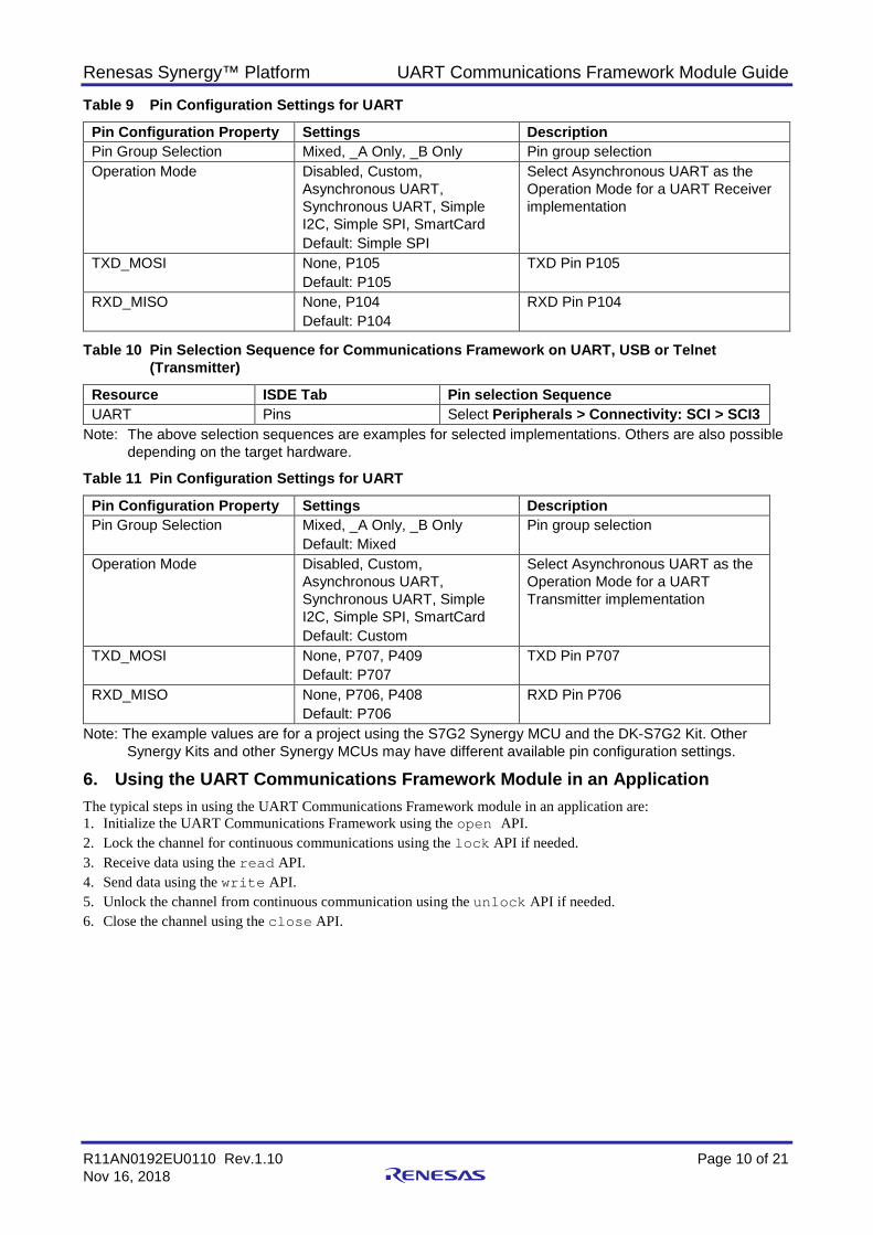
10. Compile the project. 11. Connect to the host PC via a micro USB cable to J19 on the SK-S7G2 MCU. 12. Start to debug the application. 13. The output can be viewed: Renesas Debug Virtual Console.
Figure 8 Example Output from Communications Framework Application Project

Renesas Synergy™ Platform UART Communications Framework Module Guide
R11AN0192EU0110 Rev.1.10 Page 19 of 21 Nov 16, 2018
10. UART Communications Framework Module Conclusion This module guide has provided all the background information needed to select, add, configure, and use the module in an example project. Many of these steps were time consuming and error-prone activities in previous generations of embedded systems. The Renesas Synergy Platform makes these steps much less time consuming and removes the common errors, like conflicting configuration settings or the incorrect selection of lower-level drivers. The use of high-level APIs (as demonstrated in the application project) illustrates additional development time savings by allowing work to begin at a high level and avoiding the time required in older development environments to use or, in some cases, create, lower-level drivers.
11. UART Communications Framework Module Next Steps After you have mastered a simple UART Framework Communication project, you may want to review a more complex example. You may want to explore the use of the Communications Framework implemented on other interfaces – Renesas Synergy Software Platform implements this framework on the UX and Ethernet interfaces as well.
12. UART Communications Framework Module Reference Information SSP User Manual: Available in html format in the SSP distribution package and as a pdf from the Renesas Synergy Gallery.
Links to all the most up-to-date sf_uart_comms module reference materials and resources are available on the Synergy Knowledge Base: https://en-us.knowledgebase.renesas.com/English_Content/Renesas_Synergy%E2%84%A2_Platform/Renesas_Synergy_Knowledge_Base/SF_UART_Comms_Module_Guide_Resources.

Renesas Synergy™ Platform UART Communications Framework Module Guide
R11AN0192EU0110 Rev.1.10 Page 20 of 21 Nov 16, 2018
Website and Support Visit the following vanity URLs to learn about key elements of the Synergy Platform, download components and related documentation, and get support.
Synergy Software renesassynergy.com/software Synergy Software Package renesassynergy.com/ssp Software add-ons renesassynergy.com/addons Software glossary renesassynergy.com/softwareglossary
Development tools renesassynergy.com/tools
Synergy Hardware renesassynergy.com/hardware Microcontrollers renesassynergy.com/mcus MCU glossary renesassynergy.com/mcuglossary Parametric search renesassynergy.com/parametric
Kits renesassynergy.com/kits
Synergy Solutions Gallery renesassynergy.com/solutionsgallery Partner projects renesassynergy.com/partnerprojects
Application projects renesassynergy.com/applicationprojects Self-service support resources:
Documentation renesassynergy.com/docs Knowledgebase renesassynergy.com/knowledgebase Forums renesassynergy.com/forum Training renesassynergy.com/training Videos renesassynergy.com/videos Chat and web ticket renesassynergy.com/support

Renesas Synergy™ Platform UART Communications Framework Module Guide
R11AN0192EU0110 Rev.1.10 Page 21 of 21 Nov 16, 2018
Revision History
Rev. Date Description Page Summary
1.00 Sep 14, 2017 - Initial version 1.01 Dec 7, 2017 - Replaced the hardware control example with the correct file. 1.02 Jan 9, 2018 - Minor edits for grammar and usage 1.10 Nov 16, 2018 - Updated for SSP v1.5.0
All trademarks and registered trademarks are the property of their respective owners.

http://www.renesas.comSALES OFFICES
© 2018 Renesas Electronics Corporation. All rights reserved.Colophon 7.2
(Rev.4.0-1 November 2017)
Notice1. Descriptions of circuits, software and other related information in this document are provided only to illustrate the operation of semiconductor products and application examples. You are fully responsible for
the incorporation or any other use of the circuits, software, and information in the design of your product or system. Renesas Electronics disclaims any and all liability for any losses and damages incurred by
you or third parties arising from the use of these circuits, software, or information.
2. Renesas Electronics hereby expressly disclaims any warranties against and liability for infringement or any other claims involving patents, copyrights, or other intellectual property rights of third parties, by or
arising from the use of Renesas Electronics products or technical information described in this document, including but not limited to, the product data, drawings, charts, programs, algorithms, and application
examples.
3. No license, express, implied or otherwise, is granted hereby under any patents, copyrights or other intellectual property rights of Renesas Electronics or others.
4. You shall not alter, modify, copy, or reverse engineer any Renesas Electronics product, whether in whole or in part. Renesas Electronics disclaims any and all liability for any losses or damages incurred by
you or third parties arising from such alteration, modification, copying or reverse engineering.
5. Renesas Electronics products are classified according to the following two quality grades: “Standard” and “High Quality”. The intended applications for each Renesas Electronics product depends on the
product’s quality grade, as indicated below.
"Standard": Computers; office equipment; communications equipment; test and measurement equipment; audio and visual equipment; home electronic appliances; machine tools; personal electronic
equipment; industrial robots; etc.
"High Quality": Transportation equipment (automobiles, trains, ships, etc.); traffic control (traffic lights); large-scale communication equipment; key financial terminal systems; safety control equipment; etc.
Unless expressly designated as a high reliability product or a product for harsh environments in a Renesas Electronics data sheet or other Renesas Electronics document, Renesas Electronics products are
not intended or authorized for use in products or systems that may pose a direct threat to human life or bodily injury (artificial life support devices or systems; surgical implantations; etc.), or may cause
serious property damage (space system; undersea repeaters; nuclear power control systems; aircraft control systems; key plant systems; military equipment; etc.). Renesas Electronics disclaims any and all
liability for any damages or losses incurred by you or any third parties arising from the use of any Renesas Electronics product that is inconsistent with any Renesas Electronics data sheet, user’s manual or
other Renesas Electronics document.
6. When using Renesas Electronics products, refer to the latest product information (data sheets, user’s manuals, application notes, “General Notes for Handling and Using Semiconductor Devices” in the
reliability handbook, etc.), and ensure that usage conditions are within the ranges specified by Renesas Electronics with respect to maximum ratings, operating power supply voltage range, heat dissipation
characteristics, installation, etc. Renesas Electronics disclaims any and all liability for any malfunctions, failure or accident arising out of the use of Renesas Electronics products outside of such specified
ranges.
7. Although Renesas Electronics endeavors to improve the quality and reliability of Renesas Electronics products, semiconductor products have specific characteristics, such as the occurrence of failure at a
certain rate and malfunctions under certain use conditions. Unless designated as a high reliability product or a product for harsh environments in a Renesas Electronics data sheet or other Renesas
Electronics document, Renesas Electronics products are not subject to radiation resistance design. You are responsible for implementing safety measures to guard against the possibility of bodily injury, injury
or damage caused by fire, and/or danger to the public in the event of a failure or malfunction of Renesas Electronics products, such as safety design for hardware and software, including but not limited to
redundancy, fire control and malfunction prevention, appropriate treatment for aging degradation or any other appropriate measures. Because the evaluation of microcomputer software alone is very difficult
and impractical, you are responsible for evaluating the safety of the final products or systems manufactured by you.
8. Please contact a Renesas Electronics sales office for details as to environmental matters such as the environmental compatibility of each Renesas Electronics product. You are responsible for carefully and
sufficiently investigating applicable laws and regulations that regulate the inclusion or use of controlled substances, including without limitation, the EU RoHS Directive, and using Renesas Electronics
products in compliance with all these applicable laws and regulations. Renesas Electronics disclaims any and all liability for damages or losses occurring as a result of your noncompliance with applicable
laws and regulations.
9. Renesas Electronics products and technologies shall not be used for or incorporated into any products or systems whose manufacture, use, or sale is prohibited under any applicable domestic or foreign laws
or regulations. You shall comply with any applicable export control laws and regulations promulgated and administered by the governments of any countries asserting jurisdiction over the parties or
transactions.
10. It is the responsibility of the buyer or distributor of Renesas Electronics products, or any other party who distributes, disposes of, or otherwise sells or transfers the product to a third party, to notify such third
party in advance of the contents and conditions set forth in this document.
11. This document shall not be reprinted, reproduced or duplicated in any form, in whole or in part, without prior written consent of Renesas Electronics.
12. Please contact a Renesas Electronics sales office if you have any questions regarding the information contained in this document or Renesas Electronics products.
(Note 1) “Renesas Electronics” as used in this document means Renesas Electronics Corporation and also includes its directly or indirectly controlled subsidiaries.
(Note 2) “Renesas Electronics product(s)” means any product developed or manufactured by or for Renesas Electronics.
Refer to "http://www.renesas.com/" for the latest and detailed information.
Renesas Electronics CorporationTOYOSU FORESIA, 3-2-24 Toyosu, Koto-ku, Tokyo 135-0061, JapanRenesas Electronics America Inc.1001 Murphy Ranch Road, Milpitas, CA 95035, U.S.A.Tel: +1-408-432-8888, Fax: +1-408-434-5351Renesas Electronics Canada Limited9251 Yonge Street, Suite 8309 Richmond Hill, Ontario Canada L4C 9T3Tel: +1-905-237-2004Renesas Electronics Europe LimitedDukes Meadow, Millboard Road, Bourne End, Buckinghamshire, SL8 5FH, U.KTel: +44-1628-651-700Renesas Electronics Europe GmbHArcadiastrasse 10, 40472 Düsseldorf, GermanyTel: +49-211-6503-0, Fax: +49-211-6503-1327Renesas Electronics (China) Co., Ltd.Room 1709 Quantum Plaza, No.27 ZhichunLu, Haidian District, Beijing, 100191 P. R. ChinaTel: +86-10-8235-1155, Fax: +86-10-8235-7679Renesas Electronics (Shanghai) Co., Ltd.Unit 301, Tower A, Central Towers, 555 Langao Road, Putuo District, Shanghai, 200333 P. R. ChinaTel: +86-21-2226-0888, Fax: +86-21-2226-0999Renesas Electronics Hong Kong LimitedUnit 1601-1611, 16/F., Tower 2, Grand Century Place, 193 Prince Edward Road West, Mongkok, Kowloon, Hong KongTel: +852-2265-6688, Fax: +852 2886-9022Renesas Electronics Taiwan Co., Ltd.13F, No. 363, Fu Shing North Road, Taipei 10543, TaiwanTel: +886-2-8175-9600, Fax: +886 2-8175-9670Renesas Electronics Singapore Pte. Ltd.80 Bendemeer Road, Unit #06-02 Hyflux Innovation Centre, Singapore 339949Tel: +65-6213-0200, Fax: +65-6213-0300Renesas Electronics Malaysia Sdn.Bhd.Unit 1207, Block B, Menara Amcorp, Amcorp Trade Centre, No. 18, Jln Persiaran Barat, 46050 Petaling Jaya, Selangor Darul Ehsan, MalaysiaTel: +60-3-7955-9390, Fax: +60-3-7955-9510Renesas Electronics India Pvt. Ltd.No.777C, 100 Feet Road, HAL 2nd Stage, Indiranagar, Bangalore 560 038, IndiaTel: +91-80-67208700, Fax: +91-80-67208777Renesas Electronics Korea Co., Ltd.17F, KAMCO Yangjae Tower, 262, Gangnam-daero, Gangnam-gu, Seoul, 06265 KoreaTel: +82-2-558-3737, Fax: +82-2-558-5338