U S E R ' S G U I D E - ARM Research Facility
29
U S E R ' S G U I D E ORG-115-DA OPTICAL PRECIPITATION SENSOR July 2000 OPTICAL SCIENTIFIC, INC. 205 Perry Parkway, Suite 14 Tel: (301) 670-2100 Gaithersburg, MD 20877 USA PDF created with pdfFactory trial version www.pdffactory.com
Transcript of U S E R ' S G U I D E - ARM Research Facility

U S E R ' S G U I D EORG-115-DA
OPTICAL PRECIPITATION SENSOR
July 2000
OPTICAL SCIENTIFIC, INC. 205 Perry Parkway, Suite 14Tel: (301) 670-2100 Gaithersburg, MD 20877 USA
PDF created with pdfFactory trial version www.pdffactory.com

Revision Record
Rev Date Description of Changes
5/30/96 New
7/31/00 Changed company name
Be sure to read the entire User’s Guide before proceedingwith installation or maintenance of the ORG!
PDF created with pdfFactory trial version www.pdffactory.com

OPTICAL SCIENTIFIC, INC. ORG-115-DA USER'S GUIDE
1102-907 7/31/00i
TABLE OF CONTENTS
1. INTRODUCTION TO THE ORG-115 OPTICAL PRECIPITATION GAUGE . . . . . . . . 1-11.1 The ORG-115 Improves Your Ability To Measure Rain . . . . . . . . . . . . . . . . . 1-11.2 Performance Specifications for the ORG-115 . . . . . . . . . . . . . . . . . . . . . . . . 1-31.3 How The MINI-ORG Measures Precipitation . . . . . . . . . . . . . . . . . . . . . . . . . 1-51.4 Accessories For The MINI-ORG . . . . . . . . . . . . . . . . . . . . . . . . . . . . . . . . . . 1-7
2. INSTALLATION OF THE ORG-115 MINI-ORG . . . . . . . . . . . . . . . . . . . . . . . . . . . . . 2-12.1 Mounting the MINI-ORG Sensor . . . . . . . . . . . . . . . . . . . . . . . . . . . . . . . . . . 2-12.2 Connecting the MINI-ORG Sensor . . . . . . . . . . . . . . . . . . . . . . . . . . . . . . . . . 2-3
3. MINI-ORG THEORY OF OPERATION . . . . . . . . . . . . . . . . . . . . . . . . . . . . . . . . . . . 3-13.1 Overall System Theory . . . . . . . . . . . . . . . . . . . . . . . . . . . . . . . . . . . . . . . . . 3-1
4. MINI-ORG OPERATION . . . . . . . . . . . . . . . . . . . . . . . . . . . . . . . . . . . . . . . . . . . . . . 4-14.1 Sensor Output Characteristics . . . . . . . . . . . . . . . . . . . . . . . . . . . . . . . . . . . . 4-14.2 Data Acquisition Requirements . . . . . . . . . . . . . . . . . . . . . . . . . . . . . . . . . . . 4-34.3 MINI-ORG Operation - A Typical Application . . . . . . . . . . . . . . . . . . . . . . . . . 4-5
5. MAINTENANCE & TROUBLESHOOTING THE ORG-115 . . . . . . . . . . . . . . . . . . . . 5-15.1 Routine Maintenance and Quick Check . . . . . . . . . . . . . . . . . . . . . . . . . . . . . 5-15.2 MINI-ORG Calibration Verification . . . . . . . . . . . . . . . . . . . . . . . . . . . . . . . . . 5-3
LIST OF FIGURES
Figure 1.1-1 OSi ORG-115 Series Optical Sensor . . . . . . . . . . . . . . . . . . . . . . . . . . . . . . . 1-2Figure 1.2-1 Dimensions of the ORG-115 . . . . . . . . . . . . . . . . . . . . . . . . . . . . . . . . . . . . . 1-4Figure 1.3-1 ORG-115 Major Components . . . . . . . . . . . . . . . . . . . . . . . . . . . . . . . . . . . . . 1-6Figure 1.4-1 PSB-715 Electrical Box . . . . . . . . . . . . . . . . . . . . . . . . . . . . . . . . . . . . . . . . . 1-7Figure 1.4-2 TST-800 Series Test Kit . . . . . . . . . . . . . . . . . . . . . . . . . . . . . . . . . . . . . . . . . 1-8Figure 2.1-1 Mounting the MINI-ORG . . . . . . . . . . . . . . . . . . . . . . . . . . . . . . . . . . . . . . . . . 2-2Figure 2.2-1 MINI-ORG Sensor Connections . . . . . . . . . . . . . . . . . . . . . . . . . . . . . . . . . . . 2-4Figure 3.1-1 OSi ORG-115 Sensor Block Diagram . . . . . . . . . . . . . . . . . . . . . . . . . . . . . . . 3-2Figure 4.1-1 MINI-ORG Voltage vs. Rain Rate . . . . . . . . . . . . . . . . . . . . . . . . . . . . . . . . . . 4-2Figure 5.1-1 Comb Test Procedure . . . . . . . . . . . . . . . . . . . . . . . . . . . . . . . . . . . . . . . . . . 5-2Figure 5.2-1 TST-800 Series Test Kit . . . . . . . . . . . . . . . . . . . . . . . . . . . . . . . . . . . . . . . . . 5-4
PDF created with pdfFactory trial version www.pdffactory.com

OPTICAL SCIENTIFIC, INC. ORG-115-DA USER'S GUIDE
1102-907 7/31/00ii
Note :Used to call attention to a special feature or procedure which
must be followed for correct operation of the equipment
Caution :Used to call attention to a concern where damageto the equipment or injury to personnel may occur
unless certain steps are followed
Warning :Used to call attention to a concern where serious personal
injury or death may occur unless basic safetyprocedures are followed
CAUTIONARY NOTES:
WARRANTY
Optical Scientific warrants its products to be free of defects in workmanship and materialfor a period of 12 months from date of shipment. During the warranty period, OSi willrepair or replace defective products at its own expense, subject to the following conditions:
1. The Buyer prepays all shipping, insurance, and associated costs to returnthe defective item to OSi. OSi pays return shipping and insurance.
2. The product must not have experienced misuse, neglect, accident or havebeen altered or repaired by the Buyer during the warranty period.
3. This warranty and OSi's obligation are in lieu of all other warranties. Impliedwarranties shall not apply.
4. OSi is not liable for consequential or incidental damages, labor performedin conjunction with removal and replacement, loss of production, or any otherloss incurred because of interruption of service or production of incorrect orincomplete weather information.
PDF created with pdfFactory trial version www.pdffactory.com

OPTICAL SCIENTIFIC, INC. ORG-115-DA USER'S GUIDE
1102-907 7/31/00iii
GLOSSARY
A/D Analog to DigitalADC Analog to Digital ConverterAGC Automatic Gain ControlAWG American Wire GaugeASOS Automated Surface Observing SystemCXR CarrierCW Continuous WaveDC Direct CurrentFAA Federal Aviation AdministrationIRED Infrared Light Emitting DiodeLED Light Emitting DiodeIR InfraredMOV Metal Oxide VaristorNEMA National Electrical Manufacturer's AssociationNWS National Weather ServiceORG Optical Rain GaugePSB Power Supply BoxRMA Return Material AuthorizationRX ReceiverOSi Optical Scientific, Inc.TX TransmitterVDC Voltage Direct Current
ENGLISH/METRIC CONVERSION FACTORS
1 inch = 25.4 mm 1 mm = 0.039 in
1 foot = 0.305 m 1 meter = 3.28 ft
1 pound = 0.454 kg 1 kilogram = 2.2 lbs
°F = 9/5 °C + 32 °C = 5/9( °F - 32)
PDF created with pdfFactory trial version www.pdffactory.com

OPTICAL SCIENTIFIC, INC. ORG-115-DA USER'S GUIDE
1102-907 7/31/001-1
1. INTRODUCTION TO THE ORG-115 OPTICAL PRECIPITATION GAUGE
1.1 The ORG-115 Improves Your Ability To Measure Rain
Unlike other rain gauges, the MINI-ORG® measures rain rate and provides ananalog voltage equivalent to the measured rain rate. It is vastly superior totraditional type sensors and offers the reliability and proven performance you need!
Unlike other sensors, the OSi's ORG-115 sensor provides accurate measurementof rain intensity (rate). Designed for rugged, unattended operation, the ORG-115has been field proven in adverse environments around the world, on land and atsea .
Optical Measurement Benefits
OSi Optical Rain Gauges are not affected by many of the environmental factorswhich cause significant errors with traditional rain and snow gauges. Traditionalgauges such as tipping bucket, siphon, weighing, and electrical grid type gaugescan all be replaced with the OSi MINI-ORG sensors. OSi MINI-ORG's have manyadvantages including:
Easy Installation Wide Dynamic Range
High Sensitivity No Evaporation or Splash Errors
Low Maintenance Operate on Ships & Buoys
Minimal Wind Effects Not Effected by Insects, Debris, Dust
Reliability
The electro-optical design provides for an extremely reliable sensor with acalculated MTBF in excess of 60,000 hours. Unlike mechanical gauges whichcollect the precipitation to measure it, the MINI-ORG has no collectors, buckets, orsiphons to corrode or clog. The sensors use AGC circuitry to eliminate the effectsof LED output power or dirty optics. In fact, sensor performance is maintainedeven when over 75% of the light is blocked! Diagnostics alert the user if the signalstrength is too low for normal operation. Preventative maintenance, suggestedevery 6 months, is as simple as cleaning the 2 optical windows on the unit. Thecalibration can be verified on an annual basis using the optional OSi TST-800Series Test Kit. This test can be performed in the field without removing the sensorfrom the system.
PDF created with pdfFactory trial version www.pdffactory.com

OPTICAL SCIENTIFIC, INC. ORG-115-DA USER'S GUIDE
1102-907 7/31/001-2
Proven Technology
The ORG-115 sensors are based on technology developed and patented by OSi.OSi was granted patents in the following countries USA 4754149, UK 22001510,and Canada 1285044. This technology is the basis for the present weather sensorsupplied to the FAA/NWS/U.S. Navy for the Automated Surface Observing System(ASOS). ASOS is currently being deployed at over 800 airports.
Figure 1.1-1 OSi ORG-115 Series Optical Sensor
ORG® is a registered trademark of OSi.
PDF created with pdfFactory trial version www.pdffactory.com

OPTICAL SCIENTIFIC, INC. ORG-115-DA USER'S GUIDE
1102-907 7/31/001-3
1.2 Performance Specifications for the ORG-115
The ORG-115 was designed to measure liquid precipitation (rain) rate in abovefreezing conditions.
The specifications of the MINI-ORG are as follows:
PerformanceSpecification
Rain Dynamic Range 0.1 to 500 mm/hr - standard 0.5 to 2000 mm/hr - optional
Rain Accumulation 0.001 to 999.999 mm
Rain Accuracy 5% Accumulation
Rain Resolution Determined by user equipment
Time Constant 15 seconds
Electrical Specification
Power Requirements 11 - 16 VDC @ 25 ma nominal, 30 ma maximum
Fusing User supplied 0.125 A Slow Blow recommended
Signal Output 0-5 VDC analog
Transient Protection All power and signal lines protected by MOV
Environmental Specification
Temperature 1 to 50°C
Humidity 0-100%
Precipitation/Dust NEMA-4 type protection
PDF created with pdfFactory trial version www.pdffactory.com

OPTICAL SCIENTIFIC, INC. ORG-115-DA USER'S GUIDE
1102-907 7/31/001-4
PhysicalSpecification
Size 506 mm L x 138 mm H x 168 mm W(20 in L x 4.3 in H x 6.5 in W)
Weight 1.6 kg (3.5 lbs)
Cable Length 15 meter (50 ft)
Figure 1.2-1 Dimensions of the ORG-115
PDF created with pdfFactory trial version www.pdffactory.com
OPTICAL SCIENTIFIC, INC. ORG-115-DA USER'S GUIDE
1102-907 7/31/001-5
Note :The MINI-ORG contains no user serviceable parts - do not open!
1.3 How The MINI-ORG Measures Precipitation
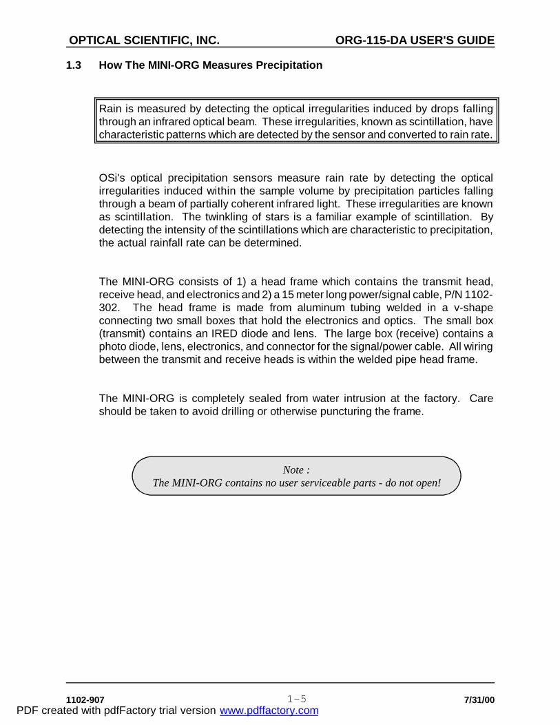
Rain is measured by detecting the optical irregularities induced by drops fallingthrough an infrared optical beam. These irregularities, known as scintillation, havecharacteristic patterns which are detected by the sensor and converted to rain rate.
OSi's optical precipitation sensors measure rain rate by detecting the opticalirregularities induced within the sample volume by precipitation particles fallingthrough a beam of partially coherent infrared light. These irregularities are knownas scintillation. The twinkling of stars is a familiar example of scintillation. Bydetecting the intensity of the scintillations which are characteristic to precipitation,the actual rainfall rate can be determined.
The MINI-ORG consists of 1) a head frame which contains the transmit head,receive head, and electronics and 2) a 15 meter long power/signal cable, P/N 1102-302. The head frame is made from aluminum tubing welded in a v-shapeconnecting two small boxes that hold the electronics and optics. The small box(transmit) contains an IRED diode and lens. The large box (receive) contains aphoto diode, lens, electronics, and connector for the signal/power cable. All wiringbetween the transmit and receive heads is within the welded pipe head frame.
The MINI-ORG is completely sealed from water intrusion at the factory. Careshould be taken to avoid drilling or otherwise puncturing the frame.
PDF created with pdfFactory trial version www.pdffactory.com

OPTICAL SCIENTIFIC, INC. ORG-115-DA USER'S GUIDE
1102-907 7/31/001-6
Caution :Do NOT drill holes in any portion of the MINI-ORG frame!
Doing so will void the warranty and may allow waterto enter the enclosure !
Figure 1.3-1 ORG-115 Major Components
PDF created with pdfFactory trial version www.pdffactory.com

OPTICAL SCIENTIFIC, INC. ORG-115-DA USER'S GUIDE
1102-907 7/31/001-7
1.4 Accessories For The MINI-ORG
Several accessories are available from OSi for the MINI-ORG. Contact the SalesOffice for more information.
Electrical Box
The PSB-715 Electrical Box includes a 12 VDC power supply and terminalstrips for connecting the MINI-ORG to the user supplied equipment. Figure1.4-1 illustrates a typical PSB box.
Figure 1.4-1 PSB-715 Electrical Box
PDF created with pdfFactory trial version www.pdffactory.com

OPTICAL SCIENTIFIC, INC. ORG-115-DA USER'S GUIDE
1102-907 7/31/001-8
Field Test Kit
The TST-800 Series Test Kit provides a convenient way to verify the MINI-ORGoperation and calibration. Figure 1.4-2 shows the TST-800.
Figure 1.4-2 TST-800 Series Test Kit
PDF created with pdfFactory trial version www.pdffactory.com
OPTICAL SCIENTIFIC, INC. ORG-115-DA USER'S GUIDE
1102-907 7/31/002-1
Caution :The MINI-ORG is a rugged instrument but it will be damaged
if dropped or handled roughly!
2. INSTALLATION OF THE ORG-115 MINI-ORG
2.1 Mounting the MINI-ORG Sensor
The ORG-115 may be installed almost anywhere outdoors but a few precautionswill help insure good sensor performance.
The MINI-ORG is packed in a heavy walled corrugated carton that contains theMINI-ORG sensor, cable, and User's Guide. When opening the carton be carefulto avoid spilling the contents. Report any shortage or shipping damage to OSiwithin 3 days of receipt.
The MINI-ORG should be mounted as shown in Figure 2.1-1. The piece of metalpipe used to mount the sensor should be stiff and well supported so that the sensordoes not sway or vibrate in the wind.
The following factors should be considered before mounting the MINI-ORG:
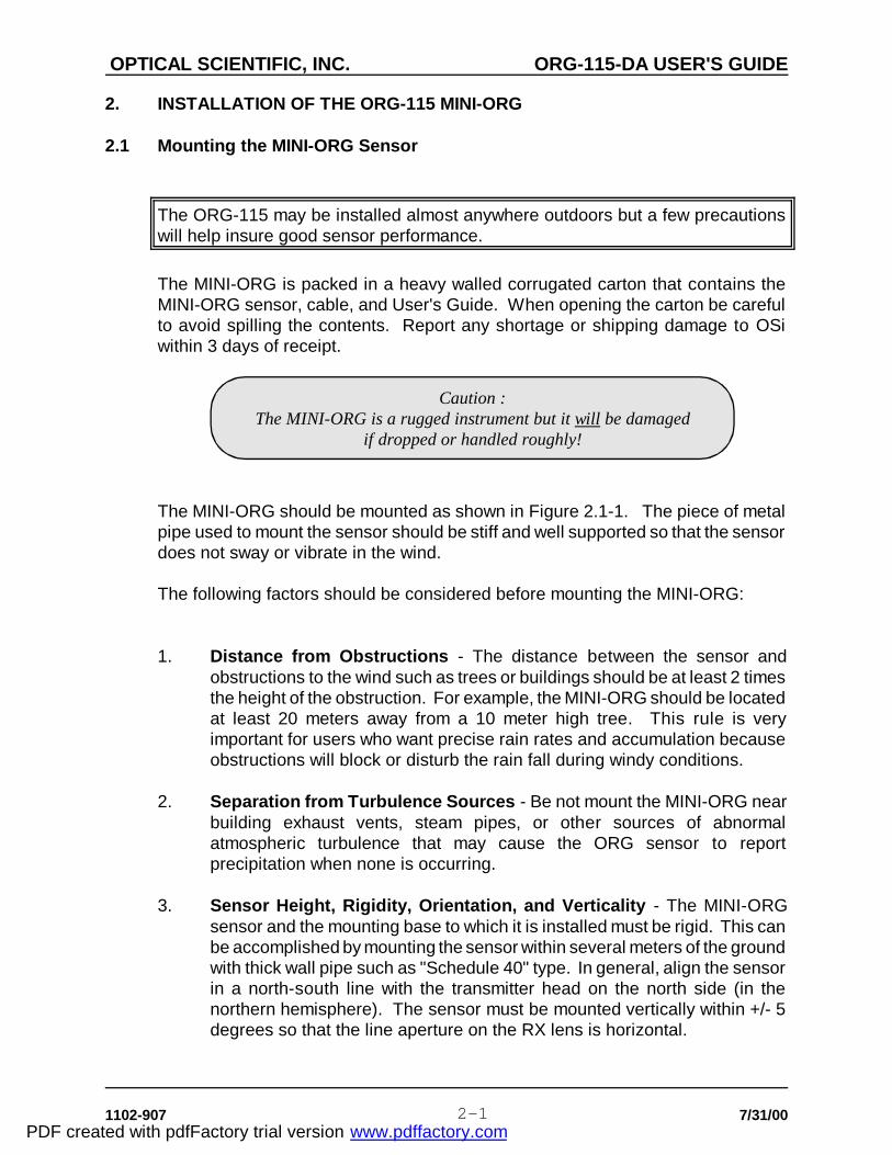
1. Distance from Obstructions - The distance between the sensor andobstructions to the wind such as trees or buildings should be at least 2 timesthe height of the obstruction. For example, the MINI-ORG should be locatedat least 20 meters away from a 10 meter high tree. This rule is veryimportant for users who want precise rain rates and accumulation becauseobstructions will block or disturb the rain fall during windy conditions.
2. Separation from Turbulence Sources - Be not mount the MINI-ORG nearbuilding exhaust vents, steam pipes, or other sources of abnormalatmospheric turbulence that may cause the ORG sensor to reportprecipitation when none is occurring.
3. Sensor Height, Rigidity, Orientation, and Verticality - The MINI-ORGsensor and the mounting base to which it is installed must be rigid. This canbe accomplished by mounting the sensor within several meters of the groundwith thick wall pipe such as "Schedule 40" type. In general, align the sensorin a north-south line with the transmitter head on the north side (in thenorthern hemisphere). The sensor must be mounted vertically within +/- 5degrees so that the line aperture on the RX lens is horizontal.
PDF created with pdfFactory trial version www.pdffactory.com

OPTICAL SCIENTIFIC, INC. ORG-115-DA USER'S GUIDE
1102-907 7/31/002-2
Caution :Do NOT drill holes in any portion of the MINI-ORG frame! Doing so
will void the warranty and may allow water to enter the enclosure!
3. Availability of Indoor Location - Be sure to carefully measure the distancethat the cable will have to run between the MINI-ORG sensor and thedesired cable termination point. The standard cable length is 16 meters (50feet).
Figure 2.1-1 Mounting the MINI-ORG
PDF created with pdfFactory trial version www.pdffactory.com

OPTICAL SCIENTIFIC, INC. ORG-115-DA USER'S GUIDE
1102-907 7/31/002-3
2.2 Connecting the MINI-ORG Sensor
Sensor connections are made to the free end of the MINI-ORG cable for all powerand signal functions.
The normal installation of the MINI-ORG requires the user to supply a 12 VDCpower source and junction box at the end of the cable. The wiring instructionsprovided here assume that the user is supplying these items. If the MINI-ORGsensor was purchased with the optional PSB-715 Electrical Box, refer to the User'sGuide for the Electrical Box for wiring instructions.
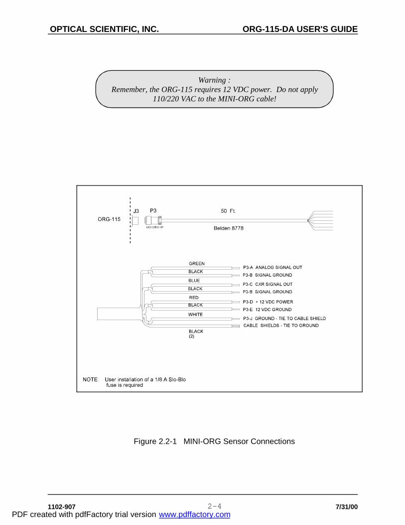
Connect the wires in the MINI-ORG sensor cable as shown in the table below andin Figure 2.2-1.
MINI-ORG WireColor
Function Connect To UserEquipment ...
Red (RD) + 12 VDC Power Supply +12 VDC
Black (BK) 12 VDC Common Power Supply Common
Green (GR) Analog Signal Output Analog Signal Input
Blue(BL) Carrier (CXR) Signal Output Analog Signal Input(Optional)
Black (BK) Signal Ground Signal Common
White (WH) Ground Earth Ground
Black (BK) Signal Ground Signal Common
Black (BK) Cable Shield (2) Earth Ground
The blue wire carries a diagnostic signal (CXR) that represents the strength of theIRED signal level between the transmitter and receiver. If this signal will not beconnected to the user supplied equipment, isolate the wire with electrical tape toprevent it from shorting to another wire.
PDF created with pdfFactory trial version www.pdffactory.com
OPTICAL SCIENTIFIC, INC. ORG-115-DA USER'S GUIDE
1102-907 7/31/002-4
Warning :Remember, the ORG-115 requires 12 VDC power. Do not apply
110/220 VAC to the MINI-ORG cable!
Figure 2.2-1 MINI-ORG Sensor Connections
PDF created with pdfFactory trial version www.pdffactory.com

OPTICAL SCIENTIFIC, INC. ORG-115-DA USER'S GUIDE
1102-907 7/31/003-1
3. MINI-ORG THEORY OF OPERATION
3.1 Overall System Theory
The MINI-ORG is an electro-optical sensor consisting of optics and analogelectronics housed in a weather-tight aluminum enclosure.
A block diagram of the ORG-115 Sensor is shown in Figure 3.1-1. The sensorconsists of:
- A transmit modulator and IR Light Emitting Diode (TX)- A transmitter optical lens assembly- A receiver optical lens assembly- A photodetector and preamplifier (RX)- An Automatic Gain Controlled (AGC) normalizer- And a signal processor with diagnostic channel
The MINI-ORG uses an infrared light emitting diode (IRED) as a light source. TheIRED is modulated to eliminate interference in the system caused by backgroundlight. The IRED has a very long lifetime, is relatively low power, invisible to the eye,and presents no radiation hazard to the user.
The IRED is housed in a smaller of the two boxes, the entire subassembly beingreferred to as the transmitter or source. The IRED is driven by a square wavecontinuous wave (CW) modulation circuit at 50 percent duty cycle and at a fixedfrequency. A lens is used to collimate the IRED's CW modulated light into a slightlydiverged beam.
The rectangular box houses the receive optics, DC regulator, the AGC, and signalprocessing electronics. The receive lens focuses the transmitted light onto a photodiode. The scintillations in light intensity are thus detected and amplified. A widedynamic range Automatic Gain Control (AGC) circuit normalizes the precipitationinduced scintillation signal to the (CW modulated) carrier. This eliminates errorsfrom variations in the source intensity caused by LED aging or dirt on the lenses.The carrier (CXR) signal strength is monitored and made available to the user fordiagnostics purposes.
PDF created with pdfFactory trial version www.pdffactory.com

OPTICAL SCIENTIFIC, INC. ORG-115-DA USER'S GUIDE
1102-907 7/31/003-2
The demodulated scintillation signal is then further filtered, processed, andaveraged. The statistical average of the measured scintillation signals give anaccurate measurement of the instantaneous rain rates. The rain rate is proportionalto the square of the signal voltage.
Figure 3.1-1 OSi ORG-115 Sensor Block Diagram
PDF created with pdfFactory trial version www.pdffactory.com

OPTICAL SCIENTIFIC, INC. ORG-115-DA USER'S GUIDE
1102-907 7/31/004-1
4. MINI-ORG OPERATION
4.1 Sensor Output Characteristics
The rain signal output of the ORG-115 Sensor is a slow-varying (0.066 Hz timeconstant) DC voltage that is proportional to the square of the rain rate. The actualoutput level at the signal output pair will vary from 0 VDC to +5 VDC at the extremelimits. The ORG output specification is shown below.
Output Impedance: 50 ohms Signal Output: 0 to 5 VDC Time Constant: 15 seconds CXR Output 0 to 5 VDC
Time Constant 120 seconds
The signal output of the ORG-115 is described by the following formula:
Standard Calibration (500 mm/hr) Rain Rate (mm/hr) = Vout2 x 20 - 0.05
Optional Calibration (2000 mm/hr) Rain Rate (mm/hr) = Vout2 x 100 - 0.25
where Vout is the sensor output in volts DC as the rain varies over the range of 0.1to 500 mm/hr (standard) or 0.5 to 2000 mm/hr (optional). The table that followsand Figure 4.1-1 illustrate the rain rate to sensor voltage relationship.
Sensor Vout(VDC)
Rain Rate(mm/hr)
Rain Rate(mm/hr)
0.085 0.1 .47
0.5 5 25
1.0 20 100
2.0 80 400
3.5 245 1225
4.5 405 2025
5.0 500 2500
Note that the signal output is always positive, with voltages under 85 millivoltscorresponding to a "no-precipitation" (NP) condition. This allows use of the mostcommon 0 to 5 VDC unipolar type input of a data acquisition system.
During normal operation, the sensor always puts out some voltage (backgroundnoise), even during clear sky conditions. The user should apply the above rain
PDF created with pdfFactory trial version www.pdffactory.com

OPTICAL SCIENTIFIC, INC. ORG-115-DA USER'S GUIDE
1102-907 7/31/004-2
rate equation only for voltages equal to or above a fixed threshold of 85 mVDC.Otherwise, the user's equipment will report a small amount of rain at all times, dueto the "clear sky" output voltage level. ("Clear sky" is defined as the absence ofprecipitation, turbulence, and other beam disturbances).
Figure 4.1-1 MINI-ORG Voltage vs. Rain Rate
The diagnostic (CXR) output is an analog signal that can be used to monitor thestrength of the IR carrier level. The carrier will fluctuate during rain and thereforeshould not be used for diagnostic purposes when precipitation is falling. Thefollowing table provides a series of thresholds which can be used (optional) by theuser. They should be considered a general guideline - for more information,contact the OSi Service Department.
CXR Voltage Description
4.0 to 4.99 VDC Acceptable Range
2.5 to 3.99 VDC Acceptable Range, Check Unit ifDecrease Continues
Less Than 2.5 VDC Maintenance Indicated
PDF created with pdfFactory trial version www.pdffactory.com

OPTICAL SCIENTIFIC, INC. ORG-115-DA USER'S GUIDE
1102-907 7/31/004-3
4.2 Data Acquisition Requirements
The MINI-ORG can connect to any analog input data acquisition device capable ofreceiving 0-5 VDC full scale signals.
The data acquisition system used to interface to the MINI-ORG may be acommercial data logger such as those manufactured by Handar, Sutron, CoastalEnvironment, or similar, PC based A/D boards, or any such device which has ananalog-to-digital (A/D) input. To properly sample and record the sensor data, fourparameters must be addressed; input voltage range, sample resolution, samplerate, and averaging techniques.
Range & Resolution
For best results, the sensor's output should be digitized with a 10 bit, unipolaranalog-to-digital converter (ADC) at an input range of 0-5 VDC. This would be anoptimum setup. For a unipolar 10 bit ADC, the digitization error would be 10 bitsover 0 to 5 V range = 4.9 mV / step, or about 0.1 % of reading.
At the minimum, the ADC should be a single ended input, 8 bit resolution ADC overthe range of 0 to +5 VDC. The error in this case would be 0.4 % of reading.
When connecting the sensor's output to a differential type input, the signal commonleg of the input pair is typically not connected to the earth ground because a returnpath is provided in the sensor. When using single ended inputs, careful cablingand installation practices should be followed to avoid introducing ground loops.
Sample Rate
Since the MINI-ORG's final output stage has a 15 second time constant, the outputshould be sampled at a minimum of twice that rate, or once every 7.5 seconds toprevent aliasing. This is suitable for all but the most demanding applications wherethere is an interest in the fine structure of high rate precipitation events. If there isan interest in the fine structure of rain events, sample at a faster rate, such as every1 to 5 seconds. Many applications do not require such high resolution data andsample rates as infrequent as once per minute are acceptable.
PDF created with pdfFactory trial version www.pdffactory.com

OPTICAL SCIENTIFIC, INC. ORG-115-DA USER'S GUIDE
1102-907 7/31/004-4
Averaging Techniques
As previously noted, the output of the sensor is a square quantity. If any averagingor processing of the data is to be done by the user's host system, then the rawsensor output data must first be converted to rain rate prior to averaging. If theconversion to rain rate is not done first, the average will always underestimate thetrue rain rate. For example, averaging the raw voltages of 1.00 VDC & 2.00 VDC(= 1.5 VDC) and then converting to rain rate yields the incorrect value 44.95 mm/hr.Done correctly, converting the voltages to rain rate first (19.95 and 79.95 mm/hr,respectively) and then averaging yields the correct value of 49.95 mm/hr.
PDF created with pdfFactory trial version www.pdffactory.com
OPTICAL SCIENTIFIC, INC. ORG-115-DA USER'S GUIDE
1102-907 7/31/004-5
4.3 MINI-ORG Operation - A Typical Application
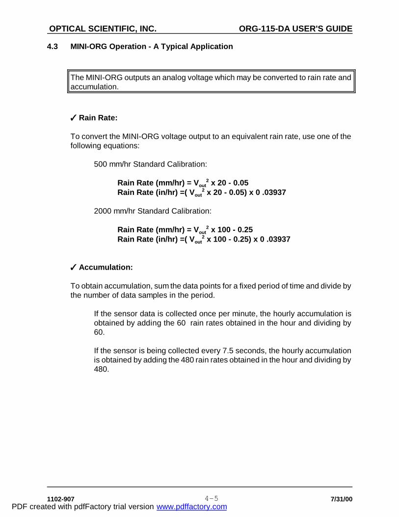
The MINI-ORG outputs an analog voltage which may be converted to rain rate andaccumulation.
Rain Rate:
To convert the MINI-ORG voltage output to an equivalent rain rate, use one of thefollowing equations:
500 mm/hr Standard Calibration:
Rain Rate (mm/hr) = Vout2 x 20 - 0.05
Rain Rate (in/hr) =( Vout2 x 20 - 0.05) x 0 .03937
2000 mm/hr Standard Calibration:
Rain Rate (mm/hr) = Vout2 x 100 - 0.25
Rain Rate (in/hr) =( Vout2 x 100 - 0.25) x 0 .03937
Accumulation:
To obtain accumulation, sum the data points for a fixed period of time and divide bythe number of data samples in the period.
If the sensor data is collected once per minute, the hourly accumulation isobtained by adding the 60 rain rates obtained in the hour and dividing by60.
If the sensor is being collected every 7.5 seconds, the hourly accumulationis obtained by adding the 480 rain rates obtained in the hour and dividing by480.
PDF created with pdfFactory trial version www.pdffactory.com

OPTICAL SCIENTIFIC, INC. ORG-115-DA USER'S GUIDE
1102-907 7/31/004-6
A typical rain event was analyzed from data collected by the OSi data acquisitionsystem. A common spreadsheet program was used to generate the graph shownbelow. Both rain rate (heavy line) and accumulation (dashed line) are shown.Note that the total accumulation for the event was 4 mm.
PDF created with pdfFactory trial version www.pdffactory.com

OPTICAL SCIENTIFIC, INC. ORG-115-DA USER'S GUIDE
1102-907 7/31/005-1
5. MAINTENANCE & TROUBLESHOOTING THE ORG-115
5.1 Routine Maintenance and Quick Check
The ORG-115 takes only a few minutes every 3-6 months to maintain. In mostcases, only simple checks are required.
Equipment Required
1. Clean Cloth or Lens Tissue2. Common Household Glass Cleaner
The MINI-ORG Sensors are designed for high reliability and low operatormaintenance. The only scheduled maintenance is to periodically clean the lenses.In most locations, cleaning the lenses every six months is recommended.Historically, the sensors have operated unattended for several years without anydegradation in performance. Use the table provided to record the maintenanceperformed.
Clean Lenses
Cleaning the lenses should be done with lint-free cloth and cleaning solution.Clean the lenses by first spraying the lens cleaner on the lens and then wipe gentlyto prevent scratching the glass optics. In actual practice, moderate dust buildupand scratches on the lenses will not have any discernible effect on the instrument.
Carrier Strength (CXR) Check
Check the strength of the carrier signal by measuring the carrier (CXR) voltage onthe blue wire. The voltage should normally be from 4.0 to 4.99 VDC if the opticalpath between the sensor heads is clear and the unit is working well. Partialblocking of the beam will cause the carrier to decrease. The carrier circuit uses atime constant on the order of one-minute and therefore will change quite slowly. If,with clean lenses and no precipitation, the carrier value is < 2.5 VDC, contact thefactory.
Background Noise Test
With no precipitation or other movement of particles through the beam, the signaloutput on the green wire referenced to ground should be <85 mV. The exact valueis dependent on the electronics noise of the sensor and atmospheric turbulencearound the MINI-ORG. If the background reading is above 85 mV during periodsof no precipitation and clear optics, inspect the sensor for proper mounting,grounding, and hook-up. If the problem persists, contact OSi for assistance.
Extremely heavy condensation (dew) on the lenses may cause the MINI-ORG AGC
PDF created with pdfFactory trial version www.pdffactory.com

OPTICAL SCIENTIFIC, INC. ORG-115-DA USER'S GUIDE
1102-907 7/31/005-2
Note :Remember, do not return anything to OSi without calling first to obtain
a return material authorization (RMA) number !
circuit to increase the background noise above 85 mV. Dry the lenses to clear theoptical path and verify that the background level returns to <85 mV.
Comb Test
Using a pocket comb, stroke it up and down vertically in front of the receiver lensas shown below for ~1 minute. Do not block the beam for any length of time. Thesignal output on the green wire referenced to ground should rise from below 85 mVbefore the comb test to up to several volts during an extended comb test.
Figure 5.1-1 Comb Test Procedure
Maintenance Check List
Date _______ Date _______ Date _______
Clean Lenses
Check Carrier
Comb Test
PDF created with pdfFactory trial version www.pdffactory.com

OPTICAL SCIENTIFIC, INC. ORG-115-DA USER'S GUIDE
1102-907 7/31/005-3
5.2 MINI-ORG Calibration Verification
The ORG-115 calibration can be verified in the field or lab using the optional TST-800 Series Field Test Kit available from OSi.
Complete MINI-ORG calibration is not a user-performed operation. ORG-715sensors are factory calibrated and sealed and should not be opened in the field.(Opening the unit will invalidate the factory warranty.) OSi provides quickturnaround calibration and repair services for all equipment it sells. Contact theSales Department for more information on calibration services. For criticalapplications, periodic verification of the calibration of the sensor is recommendedon an annual cycle. Calibration verification requires the use of a TST-800 SeriesTest Kit.
An abbreviated procedure for it's use is provided below. For more detail, follow theprocedure provided with your Test Kit when making the measurement.
1. Turn OFF power to the MINI-ORG
2. Connect the Test Kit
3. Turn ON MINI-ORG power and wait at least 10 minutes
4. Record the MINI-ORG indicated rain rate
5. Verify that the measured value is correct
6. Turn OFF power to the MINI-ORG
7. Disconnect the Test Set
11. Turn ON power to the MINI-ORG
PDF created with pdfFactory trial version www.pdffactory.com

OPTICAL SCIENTIFIC, INC. ORG-115-DA USER'S GUIDE
1102-907 7/31/005-4
Calibration Verification Table
TestDate
TST-800S/N
Measured RainRate
Initial TestRain Rate
% Delta
Figure 5.2-1 TST-800 Series Test Kit
PDF created with pdfFactory trial version www.pdffactory.com