U. S. 1, 1971 U. S. Department of Agriculture Soil...
24
U. S. Department of Agriculture Soil Conservation Service Engineering Division Design Branch February 1, 1971 DESIGN NOTE NO. 12" Subject: Control of Underground Corrosion Buried metal pipes and other mderground metal objects are subject to very rapid corrosion under ce~tain conditions, conditions which occur commonly enough to demand careful attention. A considerable number of steel irrigation pipes and galvanized steel pipe spillway conduits installed with SCS assistance have failed by corrosion after only a few years' service. The purpose of this design note is to provide interim guidance in carrying out the requirements of Engineering Standard 432-F and Engineering Memorandum-27 pertaining to corrosion control. A technical release on the general topic of underground corrosion will be issued later if it proves to be needed. Engineering Standard 432-F applies to steel irrigation pipelines. Engineering Memorandum-27 covers the use of galvanized steel and welded steel pipe in earth dams. The discussion that follows is directed toward these kinds of pipe installations. However, most of it is equally applicable to any underground or partiy underground steel structure. Aluminum alloy pipes and structures are not specifically included. They are subject to similar corrosion processes, and the same principles apply to their protection, but the properties of aluminum differ from those of steel in several important ways: (1) A natural oxide forms inmediately upon exposure of my alt~rnin~im surface to the atmosphere, which provides substantial protection against corrosion in most environments . (2) The exclusion of oxygen from portions of the surface, as by chunks of stiff clay in the backfill around a pipe, for example, promotes rapid corrosion at points where the oxide film i s broken by preventing re-formation of the natural oxide. (3) Alkaline soils and waters are especially corrosive to aluminum, while they tend to inhibit corrosion of steel. ;?By A. S. Payne, Assistant Chief, Design Branch • U. S. Department of Agriculture Soil Conservation Service Engineering Division Design Branch DESIGN NOTE NO, 12* Subject: Control of Underground Corrosion February 1, 1971 • • Buried metal pipes and other 1:nderground metal objects are subject to very rapid corrosion under ceLtain conditions, conditions which occur commonly enough to demand careful attention, A considerable number of steel irrigation pipes and galvanized steel pipe spillway conduits installed with SCS assistance have failed by corrosion after only a few years' service. The purpose of this design note is to provide interim guidance in carrying out the requirements of Engineering Standard 432-F and Engineering Memorandum-27 pertaining to corrosion control. A technical release on the general topic of underground corrosion will be issued later if it proves to be needed. Engineering Standard 432-F applies to steel irrigation pipelines. Engineering Memorandum-27 covers the use of galvanized steel and welded steel pipe in earth dams. The discussion that follows is directed toward these kinds of pipe installations. However, most of it is equally applicable to any underground or partly underground steel structure. Aluminum alloy pipes and structures are not specifically included, They are subject to similar corrosion processes, and the same principles apply to their protection, but the properties of aluminum differ from those of steel in several important ways: (1) A natural oxide forms immediately upon exposure of a'ly aluminum surface to the atmosphere, which provides substantial protection against corrosion in most enviromnents. (2) The exclusion of oxygen from portions of the surface, as by chunks of stiff clay in the backfill around a pipe, for example, promotes rapid corrosion at points where the oxide film is broken by preventing re-formation of the natural oxide. (3) Alkaline soils and water3 are especially corrosive to aluminum, while they tend to inhibit corrosion of steel. *By A. S. Payne, Assistant Chief, Design Branch
-
Upload
hoangthuan -
Category
Documents
-
view
213 -
download
0
Transcript of U. S. 1, 1971 U. S. Department of Agriculture Soil...

U. S. Department of Agr icu l ture S o i l Conservation Serv ice Engineering Div is ion Design Branch
February 1, 1971
DESIGN NOTE NO. 12"
Subjec t : Control of Underground Corrosion
Buried metal p ipes and o the r mderground meta l o b j e c t s a r e sub jec t t o very rap id co r ros ion under c e ~ t a i n cond i t i ons , cond i t i ons which occur commonly enough t o demand c a r e f u l a t t e n t i o n . A cons iderable number of s t e e l i r r i g a t i o n p ipes and galvanized s t e e l p ipe sp i l lway condui t s i n s t a l l e d with SCS a s s i s t a n c e have f a i l e d by co r ros ion a f t e r only a few y e a r s ' s e rv i ce .
The purpose o f t h i s des ign no te i s t o provide i n t e r i m guidance i n ca r ry ing out t h e requirements of Engineering Standard 432-F and Engineering Memorandum-27 p e r t a i n i n g t o co r ros ion c o n t r o l . A t echn ica l r e l e a s e on t h e genera l t o p i c of underground co r ros ion w i l l be i ssued l a t e r i f i t proves t o be needed.
Engineering Standard 432-F a p p l i e s t o s t e e l i r r i g a t i o n p i p e l i n e s . Engineering Memorandum-27 covers t h e use of galvanized s t e e l and welded s t e e l p ipe i n e a r t h dams. The d i scuss ion t h a t fol lows i s d i r e c t e d toward these k inds of p ipe i n s t a l l a t i o n s . However, most o f i t i s equal ly app l i cab le t o any underground o r p a r t i y underground s t e e l s t r u c t u r e .
Aluminum a l l o y p ipes and s t r u c t u r e s a r e not s p e c i f i c a l l y included. They a r e s u b j e c t t o s i m i l a r co r ros ion processes , and t h e same p r i n c i p l e s apply t o t h e i r p ro t ec t ion , but t h e p r o p e r t i e s of aluminum d i f f e r from those of s t e e l i n s eve ra l important ways:
(1) A n a t u r a l ox ide forms inmediately upon exposure o f m y alt~rnin~im su r face t o t h e atmosphere, which provides s u b s t a n t i a l p r o t e c t i o n aga ins t co r ros ion i n most environments .
(2) The exc lus ion of oxygen from por t ions of t h e su r f ace , a s by chunks of s t i f f c l a y i n t h e b a c k f i l l around a p ipe , f o r example, promotes rap id cor ros ion a t p o i n t s where t h e oxide f i l m i s broken by prevent ing re-formation o f t h e n a t u r a l oxide.
( 3 ) Alkal ine s o i l s and waters a r e e s p e c i a l l y co r ros ive t o aluminum, while they tend t o i n h i b i t co r ros ion of s t e e l .
;?By A. S. Payne, Ass i s t an t Chief , Design Branch
•U. S. Department of AgricultureSoil Conservation ServiceEngineering DivisionDesign Branch
DESIGN NOTE NO, 12*
Subject: Control of Underground Corrosion
February 1, 1971
•
•
Buried metal pipes and other 1:nderground metal objects are subject tovery rapid corrosion under ceLtain conditions, conditions which occurcommonly enough to demand careful attention, A considerable number ofsteel irrigation pipes and galvanized steel pipe spillway conduitsinstalled with SCS assistance have failed by corrosion after only afew years' service.
The purpose of this design note is to provide interim guidance incarrying out the requirements of Engineering Standard 432-F andEngineering Memorandum-27 pertaining to corrosion control. A technicalrelease on the general topic of underground corrosion will be issuedlater if it proves to be needed.
Engineering Standard 432-F applies to steel irrigation pipelines.Engineering Memorandum-27 covers the use of galvanized steel and weldedsteel pipe in earth dams. The discussion that follows is directedtoward these kinds of pipe installations. However, most of it isequally applicable to any underground or partly underground steelstructure.
Aluminum alloy pipes and structures are not specifically included,They are subject to similar corrosion processes, and the same principlesapply to their protection, but the properties of aluminum differ fromthose of steel in several important ways:
(1) A natural oxide forms immediately upon exposure ofa'ly aluminum surface to the atmosphere, which providessubstantial protection against corrosion in mostenviromnents.
(2) The exclusion of oxygen from portions of the surface, asby chunks of stiff clay in the backfill around a pipe,for example, promotes rapid corrosion at points where theoxide film is broken by preventing re-formation of the naturaloxide.
(3) Alkaline soils and water3 are especially corrosive toaluminum, while they tend to inhibit corrosion of steel.
*By A. S. Payne, Assistant Chief, Design Branch

( 4 ) The n a t u r a l p o t e n t i a l o f aluminum i s so c l o s e t o t h a t of z inc t h a t z inc anodes cannot be r e l i e d upon f o r ca thodic p ro t ec t ion . Magnesium anodes can be used, however.
(5) The co r ros ion of aluminum i s hastened r a t h e r than i n h i b i t e d by ca thodic p r o t e c t i o n i f t oo much cu r ren t i s appl ied .
NATURE OF CORROSION
Underground co r ros ion i s an e lec t rochemica l process s i m i l a r t o t h e a c t i o n i n a d ry c e l l b a t t e r y . It can t a k e p l a c e only when four e s s e n t i a l elements a r e present : (1) an anode, (2) a cathode, (3) an e l e c t r o l y t e , and ( 4 ) an e l e c t r i c a l conductor connect ing t h e cathode t o t h e anode. An e l e c t r o l y t e can be any l i q u i d , p a s t e , o r gas which can conduct e l e c t r i c i t y by t h e migra t ion o f i ons . I n t h e c a s e o f underground cor ros ion , t h e e l e c t r o y t e i s t h e s o i l . Moisture and d isso lved s a l t s have t o be p re sen t i n t h e s o i l t o provide t h e ions .
These fou r elements provide a complete e l e c t r i c a l c i r c u i t . An e lec t romot ive f o r c e (emf) a l s o i s necessary. It may be t h e r e s u l t of galvariic a c t i o n w i t h i n t h e c e l l o r o f s t r a y e l e c t r i c c u r r e n t from some e x t e r n a l source. Current fiows through t h e e l e c t r o l y t e from t h e anode t o the-ca thode , and through t h e conductor from t h e cathode t o t h e an0de.l
In a common d ry c e l l , che z inc case i s t h e anode, t h e carbon rod i s t h e cathcde, and t h e p a s t e with which t h e b a t t e r y i s f i l l e d i s t h e e l e c t r o l y t e . Current flows, and co r ros ion of t h e z inc c a s e t akes p l ace , when a conductor i s connected from t h e cathode t o t h e anode. In underground cor ros ion , of n p ipe f o r example, t h e s o i l i s t h e e l e c t r o l y t e and t h e p i p c i t s e l f u sua l ly i s t h e conductor. One p a r t of t h e p i p e s s s u r f a c e may be t h e anode and a n o t h e r p a r t t h e c a h a d e .
Curren"~ Ir: conductor
Cathodic rCC- t. Anodic
7
Z ~ e c t r o k y t e
D r y C e i l Bat te ry Corroding Pipe
F i g . 1 - Corrogion C e l l s
he d i r e c t i o n of c u r r e n t flow, as used throughout t h i s d i scuss ion , i s t h e convent ional d i r e c t i o n , oppos i t e t o t h e d i r e c t i o n of e l e c t r o n flow.
2
(4) The natural potential of aluminum is so close to thatof zinc that zinc anodes cannot be relied upon for cathodicprotection. Magnesium anodes can be used, however.
(5) The corrosion of aluminum is hastened rather than inhibitedby cathodic protection if too mUlh current is applied. •
NATURE OF CORROSION
Underground corrosion is an electrochemical process similar to theaction in a dry cell battery. It can take place only when fouressential elements are present: (1) an anode, (2) a cathode, (3)an electrolyte, and (4) an electrical conductor connecting thecathode to the anode. An electrolyte can be any liquid, paste, orgas vmich can conduct electricity by the migration of ions. In thecase of underground corrosion, the electroyte is the soil. Moistureand dissolved salts have to be present in the soil to provide the ions.
•
These four elements provide a complete electrical circuit. Anelectromotive force (emf) also is necessary. It may be the result ofgalvanic action within the cell or of stray electric current from someexternal source. Current flows through the electrolyte from the anodeto the cathode, and through the conductor from the cathode to theanode.1
In a common dry cell, the zinc caSe is the anode, the carbon rod isthe cathcde, and the paste with which the battery is filled is theelectrolyte. Current flows, and corrosion of the zinc case takesplace, when a conductor is connected from the cathode to the anode.In underground corrosion, of ;l pipe for example, the soil is theelectrolyte and the pipe itself usually is the conductor. One partof the pipe's surface may be the anode and another_part .the cathode.
•
Metalpipe
Anodicarea
<Currentin soil
--
Currentin pipe
Cathodicarea
Carboncathode
Currentin conductor
conducto.r }K )~;'I------ti. j II. I' I·
II I i II!!-11~N i III Currenti.1 I! r -i11_1 i--l! ....n
Electrolyte hi! Ii electrolyte
I!~I! II11_11--11
!i U II.Zinc II ,'II Iianode· ,
Dry Cell Battery Corroding Pipe
Fig. 1 - Corrosion Cells
lihe direction of current flow, as used throughout this discussion, isthe conventional direction, opposite to the direction of electron flow. •

The complete system (anode, cathode, e l e c t r o l y t e , and conductor) i s ca l l ed an e l e c t r o l y t i c o r galvanic c e l l o r corrosion c e l l . The anode and cathode may includc major areas of t h e pipe, o r they may be minute, as a t pinholes i n a p ro tec t ive coating. Rusting of i ron under a drop of water i l l u s t r a t e s t h e ac t ion of a complete corrosion c e l l within t h e drop. By d e f i n i t i o n , i n any e l e c t r o l y t i c c e l l , current flows from t h e anode t o t h e e l e c t r o l y t e and t o t h e cathode from the e l e c t r o l y t e . Corrosion takes place where current leaves t h e metal and en te r s t h e e l e c t r o l y t e , hence a t the anode.
CAUSES OF CORROSION
When the four e s s e n t i a l s of a corrosion c e l l (anode, cathode, e l e c t r o l y t e , and conductor) a r e present , as they usual ly a r e when a metal objec t i s buried i n t h e ground, t h e r a t e a t which corrosion takes p lace i n each c e l l depends upon t h e amount of e l e c t r i c current flowing, which i n t u r n depends upon t h e emf and the e l e c t r i c a l res is tance:
emf (vo l t s ) Current (amps) =
Resistance (ohms)
Thus, rapid corrosion i s promoted by a high emf and low c e l l res is tance . Since t h e e lec t ro ly te , which i s t h e s o i l , i s p a r t of t h e c e l l c i r c u i t , s o i l with a high res i s t ance r e t a r d s corrosion. Likewise, p ipe coatings having high e l e c t r i c a l r e s i s t ance i n h i b i t current flow from t h e metal t o t h e s o i l and so r e s i s t corrosion.
The condit ions t h a t can generate the emf necessary t o make a corrosion c e l l opera te a r e so numerous t h a t some of them a r e near ly always present . Following i s a p a r t i a l l i s t .
Proper t ies of t h e rcetal objec t i t s c l f Dissimilar metals connected together Flaws and inclusions i n t h e metal Forming s t r a i n s , and va r ia t ions i n i n t e r n a l s t r e s s New metal connected t o old metal Scratches, abrasions, pipe threads, e t c . , exposing clean metal M i l l s ca le
Propert ies of the s o i l o r o the r environment Variat ions i n s o i l moisture Variat ions i n aera t ion of t h e s o i l Varfations i n kind of s o i l Variat ions i n a c i d i t y o r o the r chemical proper t ies Par t of t h e metal submerged and pa r t exposed t o atmosphere Par t of t h e metal encased i n concrete and p a r t i n s o i l o r water
•3
The complete system (anode, cathode, electrolyte, and conductor) iscalled an electrolytic or galvanic cell or corrosion cell. Theanode and cathode may include major areas of the pipe, or they maybe minute, as at pinholes in a protective coating. Rusting of ironunder a drop of water illustrates the action of a complete corrosioncell within the drop. By definition, in any electrolytic cell,current flows from the anode to the electrolyte and to the cathodefrom the electrolyte. Corrosion takes place where current leaves themetal and enters the electrolyte. hence at the anode.
CAUSES OF CORROSION
When the four essentials of a corrosion cell (anode, cathode,electrolyte, and conductor) are present, as they usually are when ametal object is buried in the ground, the rate at which corrosiontakes place in each cell depends upon the amount of electric currentflowing, which in turn depends upon the emf and the electr~cal
resistance:
Current (ampS)emf (volts)
Resistance (ohms)
•
•
Thus, rapid corrosion is promoted by a high emf and low cellresistance. Since the electrolyte, which is the soil, is part ofthe cell circuit, soil with a high resistance retards corrosion.Likewise, pipe coatings having high electrical resistance inhibitcurrent flow from the metal to the soil and so resist corrosion.
The conditions that can generate the emf necessary to make a corrosioncell operate are so numerous that Some of them are nearly alwayspresent. Following is a partial list.
Properties of the metal object itSElfDissimilar metals connected togetherFlaws and inclusions in the metalForming strains, and variations in internal stressNew metal connected to old metalScratches, abrasions, pipe threads, etc., exposing clean metalMill scale
Properties of the soil or other environmentVariations in soil moistureVariations in aeration of the soilVariations in kind of soilVariations in acidity or other chemical properti~s
Part of the metal submerged and part exposed to atmospherePart of the metal encased in concrete and part in soil or water

External influences Induced current from nearby e l e c t r i c a l equipment Stray currents i n t h e s o i l from grounded e l e c t r i c a l equipment
Probably t h e most general ly recognized of these i s t h e combination of d i s s imi la r metals. For example, it i s well known t h a t s t e e l w i l l corrode very rapidly when coupled t o brass o r copper i n a corros ive environment, i .e . , i n an e l e c t r o l y t e .
GALVANIC SERIES
When a metal i s immersed i n an e l e c t r o l y t e i t developes an e l e c t r i c a l p o t e n t i a l (emf) with respect t o t h e e lec t ro ly te . The magnitude of t h i s p o t e n t i a l i s d i f f e r e n t f o r d i f f e r e n t metals. The "electromotive force se r i es" i s an arrangement of metals and t h e i r c h a r a c t e r i s t i c p o t e n t i a l s arranged i n order of increasing (posi t ive ly) po ten t i a l . The p o t e n t i a l s usual ly shown a r e a s measured with reference t o a standard hydrogen reference e lec t rode, i n an e l e c t r o l y t e consis t ing of a so lu t ion of t h e meta l ' s own s a l t s . I n o the r e l e c t r o l y t e s t h e p o t e n t i a l s a r e d i f f e r e n t , but t h e r e l a t i v e pos i t ions of t h e metals i n t h e s e r i e s usual ly a r e t h e same. Table I l i s t s c e r t a i n common metals and t h e i r p o t e n t i a l s i n t h e electromotive fo rce s e r i e s . Table I1 i s a " p r a c t i c a l galvanic se r i es" of metals and t h e i r typ ica l p o t e n t i a l s i n neu t ra l s o i l s and water when measured with respect t o a standard copper-copper s u l f a t e reference e lec t rode.
Table I Table I1
Electromotive Force ser ies1 Gz.lvanic Ser ies f o r Metals i n s o i l 3
Metal Emf - vol t s2 Metal Emf - vol t s4
Magnesium -2.37 Commercially pure magnesium -1.75
Aluminum -1.66
Zinc -0.76
Magnesium a l loy (6% A l , 3% Zn, 0.15% Mn) -1.6
-0.44 Zinc -1.1 I r o n
Tin -0.14 Aluminum a l loy (5% zinc) -1.05
Lead -0.13 Commercially pure aluminum -0.8
Hydrogen 0.00 Mild Steel (clean and shiny) -0.5 t o -0.8
Copper
S i lve r
Mild s t e e l (rusted)
Mild s t e e l i n concrete
Platinum +l. 20 Copper, brass , bronze -0.2
Gold +1.50 t o +1.68 M i l l s c a l e on s t e e l -0.2
Carbon, graphi te , coke +O. 3 'From "Handbook of Chemistry ~ r o m Peabody, "Control of Pipel ine
and Physics" corrosion "
a PatentiaT of metal i n so lu t ion 4 ~ y p i c a l p o t e n t i a l i n neu t ra l s o i l s of i t s ow. s a l t s , measured with and water, measured with respect respect t o hydrogen reference t o copper-copper s u l f a t e reference electrode. e lec t rode .
4
External influencesInduced current from nearby electrical equipmentStray currents in the soil from grounded electrical equipment •Probably the most generally recognized of these is the combination of
dissimilar metals. For example, it is well known that steel willcorrode very rapidly when coupled to brass or copper in a corrosiveenvironment, i.e., in an electrolyte.
GALVANIC SERIES
When a metal is immersed in an electrolyte it developes an electricalpotential (emf) with respect to the electrolyte. .The magnitude ofthis potential is different for different metals. The "electromotiveforce series" is an arrangement of metals and their characteristicpotentials arranged in order of increasing (positively) potential.The potentials usually shown are as measured with reference to astandard hydrogen reference electrode, in an electrolyte consistingof a solution of the metal's own salts. In other electrolytes thepotentials are different, but the relative positions of the metalsin the series usually are the same. Table I lists certain commonmetals and their potentials in the electromotive force series. TableII is a "practical galvanic series" of metals and their typicalpotentials in neutral soils and water when measured with respect toa standard copper-copper sulfate reference electrode.
Mild steel (clean and shiny) -0.5 to -0.8Mild steel (rusted) -0.2 to -0.5
Table II
Gl.lvanic Series for Metals in Soi13
Metal Emf - Volts4 •
•
-1. 75
-0.2
-0.2
-1. 6
-1.1
-1.05
-0.8
-0.2
+0.3
Aluminum alloy (5% zinc)
Copper, brass, bronze
Commercially pure aluminum
Zinc
Commercially pure magnesium
Magnesium alloy (6% AI,3% Zn, 0.15% Mn)
Mill scale on steel
Mild steel in concrete
Carbon, graphite, coke
3 From Peabody, "Control of PipelineCorrosion II
4Typical potential in neutral soilsand water, measured with respectto copper-copper sulfate referenceelectrode.
Metal Emf - Volts;'
Magnesium -2.37
Aluminum -1. 66
Zinc -0.76
Iron -0.44
Tin -0.14
Lead -0.13
Hydrogen 0.00
Copper +0.34 to +0.52
Silver +0.80
Platinum +1.20
Gold +1. 50 to +1. 68
Table I
Electromotive Force Series l
1 From" Handbook of Chemistryand Physics"
2Potential of metal in solutionof its own salts, measured withrespect to hydrogen referenceelectrode.

I n gene ra l , when any two meta ls a r e buried i n t h e ground, o r i m e r s e d i n any o t h e r e l e c t r o l y t e , and a r e connected e l e c t r i c a l l y (by an e l e c t r i c a l conductor) , a ga lvanic c e l l i s e s t ab l i shed i n which t h e meta l h igher i n t h e s e r i e s i s t h e anode and t h e meta l lower i n t h e s e r i e s i s t h e cathode.
PROTECTION AGAINST CORROSION
Coatings
Coatings which w i l l not conduct e l e c t r i c i t y o r t ransmi t mois ture a r e e f f e c t i v e i n l i m i t i n g underground cor ros ion . However, p r a c t i c a l l y a l l coa t ings have some minor flaws ("holidays") through which mois ture and e l e c t r i c c u r r e n t can pass . Corrosion tends t o concen t r a t e a t t h e flaws because they a r e t h e only p o i n t s a t which c u r r e n t can flow from t h e metal . A coated p i p e thus may be pe r fo ra t ed by co r ros ion i n l e s s t ime than an uncoated p ipe i n t h e same environment.
E l e c t r i c a l I n s u l a t i o n
Corrosion caused by d i s s i m i l a r meta ls can be prevented by e l e c t r i c a l l y i n s u l a t i n g one metal from t h e o t h e r ; f o r example, by us ing i n s u l a t i n g couplings t o connect copper p ipe and f i t t i n g s t o s t e e l pipe. I n s u l a t i o n a l s o may be app l i cab le i n c o n t r o l l i n g s t r a y cu r r en t cor ros ion .
Cathodic P ro t ec t ion
Cathodic p r o t e c t i o n of a buried p ipe c o n s i s t s of lowering t h e e l e c t r i c a l p o t e n t i a l o f t h e p ipe , r e l a t i v e t o t h e adjacent s o i l , t o t h e ex t en t char cu r r en t can flow only from t h e s o i l to t h e pipe. The whole p ipe becomes a cathode and does not corrode. A ca thodic p r o t e c t i o n i n s t a l - l a t l o n i s a cor ros ion c e l l i n which t h e p ipe i s t h e cathode and a s e p a r a t e , " s a c r a f i c i a l " anode i s provided. The anode usua l ly c o n s i s t s of a ba r , rod , o r wi re of metal o r carbon whose only func t ion i s t o be an anode. it i s expected t o corrode and, i f l e f t i n s e r v i c e long enough, t o be e s s e n t i a l l y consumed.
Cathodic p r o t e c t i o n i s provided e i t h e r by ga lvanic a c t i o n o r by impressed c u r r e n t . I n a ga lvan ic c e l l , d i s s i m i l a r meta ls a r e used f o r t h e anode ar,d cathode. When a s t e e l p ipe i s t o be p ro t ec t ed , t h e anode usua l ly i s z inc o r magnesium. I n an impressed cu r ren t c e l l , t h e emf i s suppl ied irom an o u t s i d e source of d.c . power o r , more o f t e n , c o m e r c i a l a.c. power passed through a r e c t i f i e r . The anode can be any e l e c t r i c a l conductor and usua l ly i s of a durable metal , such as a cor ros ion r e s i s t a n t c a s t i r o n , o r o f carbon.
•
•
•
5
In general, when any two metals are buried in the ground, or immersedin any other electrolyte, and are connected electrically (by anelectrical conductor), a galvanic cell is established in which themetal higher in the series is the anode and the metal lower in theseries is the cathode.
PROTECTION AGAINST CORROSION
Coatings
Coatings which will not conduct electricity or transmit moisture areeffective in limiting underground corrosion. However, practically allcoatings have some minor flaws ("holidays") through which moisture andelectric current can pass. Corrosion tends to concentrate at the flawsbecause they are the only points at which current can flow from themetal. A coated pipe thus may be perforated by corrosion in lesstime than an uncoated pipe in the same environment.
Electrical Insulation
Corrosion caused by dissimilar metals can be prevented by electricallyinsulating one metal from the other; for example, by using insulatingcouplings to connect copper pipe and fittings to steel pipe. Insulationalso may be applicable in controlling stray current corrosion.
Cathodic Protection
Cathodic protection of a buried pipe consists of lowering the electricalpotential of the pipe, relative to the adjacent soil, to the extentthat current can flow only from the soil to the pipe. The whole pipebecomes a cathode and does not corrode. A cathodic protection installation is a corrosion cell in which the pipe is the cathode and aseparate, "s.:icraficial" anode is provided. The anode usually consistsof a bar, rod, or wire of metal or carbon whose only function is tobe an anode. It is expected to corrode and, if lett in service longenough, to be essentially consumed.
Cathodic protection is provided either by galvanic action or by impressedcurrent. In a galvanic cell, dissimilar metals are used for the anodeand cathode. \~en a steel pipe is to be protected, the anode usuallyis zinc or magnesium. In an impressed current cell, the emf is suppliedfrom an outside source of d.c. power or, more often, commercial a.c.power passea through a rectifier. The anode can be any electricalconductor and usually is of a durable metal, such as a corrosionresistant cast iron, or of carbon .

Current in -tL connecting wire
zinc in soil
D. C. power source
Current in connecting
Steel pi
\-
1 Current d cast ire? - in soil
anode anode
(1) Galvanic (2) Impressed Current
Fig. 2 - Cathodic Protection TESTS FOR CORROSION CONTROL
Soil Resistivity
One of the most influential factors affecting the rate of corrosion and the design of cathodic protection is the resistivity of the soil. Resistivity is a unit measure of the electrical resistance of the soil. It is defined as the resistance of a unit cube, usually a one centimeter cube, to the passage of electric current and is expressed in resistance-length units, usually ohm-centimeter~ (ohm-cm). The resistance (R) of a given block of soil is equal to the resistivity (r) inultiplied by the length (1) in the direction of current flow, divided by the cross section area (a) perpendicular to the direction of current flow.
Soil resistivity has a major effect on the rate at which current passes from a metal surface into the soil, or from the soil into the metal, under a given emf and on the current a given anode can supply in a cathodic protection installation.
In general, resistivity decreases with increasing moisture in the soil and with increasing total salts. For practical purposes it is nearly constant for moisture contents from field capacity to saturation. The conductivity of a saturation extract of soil is used in Soil Survey measurements of total salts. This measure does not correlate well with resistivity, but does give some indication of the corrosivity of the soil. It has the advantage that it is available for many soils already tested.
D. C. power source
6
-L Current inconnecting wire
! t
--"'--- -'
~ --'CurrentZinc in soilanode
"--. ---'Cast irO"1anode
Current iny connecting wire
Steel pipe
Currentin soil
•
(1) Galvanic (2) Impressed Current
Fig. 2 - Cathodic Protection
TESTS FOR CORROSION CONTROL
Soil Resistivity
One of the most influential factors affecting the rate of corrosionand the design of cathodic protection is the resistivity of the soil.Resistivity is a unit measure of the electrical resistance of thesoil. It is defined as the resistance of a unit cube, usually a onecentimeter cube, to the passage of electric current and is expressedin resistance-length units, usually ohm-centimeters (ohm-em). Theresistance (R) of a given block of soil is equal to the resistivity (r)multiplied by the length (t) in the direction of current flow,divided by the cross section area (a) perpendicular to the directionof current flow.
•R (ohms) L (ohm-em) x t(cm)
a (cm2)
Soil resistivity has a major effect on the rate at which currentpasses from a metal surface into the soil, or from the soil into themetal, under a given emf and on the current a given anode can supplyin a cathodic protection installation.
In general, resistivity decreases with increasing moisture in thesoil and with increasing total salts. For practical purposes it isnearly constant for moisture contents from field capacity tosaturation. The conductivity of a saturation extract of soil is usedin Soil Survey measurements of total salts. This measure does notcorrelate well with resistivity, but does give some indication of thecorrosivity of the soil. It has the advantage that it is availablefor many soils already tested.
•

p i t , can be measured wi th any of va r ious models of s ing le-probe instruments . These measure t h e r e s i s t a n c e between 2 e l ec t rodes i n a probe rod which i s i n s e r t e d i n t o t h e s o i l t o be t e s t e d . The equipment i s p o r t a b l e and t e s t s can be made quickly. The s o i l may not be a t t h e mois ture content it w i l l have a f t e r t h e p ipe i s i n s t a l l e d , however, i n which c a s e t h e readings w i l l not i n d i c a t e t h e r e s i s t i v i t y t o be expected when t h e p ipe i s i n s e rv i ce . A nea r ly - sa tu ra t ed cond i t i on f o r t h e t e s t can be achieved by boring a ho le t o t h e depth a t which t h e measurement i s t o be made, pouring water i n t o i t , and al lowing t h e water t o soak i n t o t h e s o i l be fo re making t h e t e s t .
S o i l r e s i s t i v i t y should be measured before a metal p i p e i s i n s t a l l e d and in'many cases a f t e r i t i s i n s t a l l e d , a l s o , e s p e c i a l l y i f t h e s o i l mois ture i s d i f f e r e n t a f t e r t h e p i p e i s i n s t a l l e d .
Laboratory Tes ts . The S o i l Mechanics Laboratory i n Lincoln, t h e Engineering Mate r i a l s Labora tor ies i n Por t land and For t Worth, and t h e S o i l Survey Labora tor ies i n Lincoln and Rivers ide a l l a r e equipped t o make r e s i s t i v i t y measurements. They use t h e Bureau o f S o i l s r e s i s t i v i t y cup o r s i m i l a r devices , Two o r t h r e e pounds o f s o i l should be s e n t t o t h e l abo ra to ry f o r each t e s t . A device s i m i l a r i n p r i n c i p l e t o t h e r e s i s t i v i t y cup but l a r g e r i s t h e " s o i l box." Its volume i s about 35 cubic inches , whi le t h a t o f B o f S cup i s 50 m l .
Since t h e r e s i s t i v i t y o f most s o i l s decreases wi th inc reas ing mois ture content , r e s i s t i v i t y t e s t s should be made wi th t h e samples a t a mois ture content r ep re sen t ine t h e w e t t e s t cond i t i on l i k e l y t o p r e v a i l f o r any s i g n i f i c a n t t ime i n t h e v i c i n i t y of t h e p i p e a f t e r i t i s i n s t a l l e d . For metal p ipes i n e a r t h dams, t h e s o i l should be t e s t e d i n a s a t u r a t e d condi t ion . The r e s i s t i v i t y a l s o i a a f f e c t e d by s a l t s i n t h e ground water. This should be considered i n t e s t i n g s o i l s which may become s a t u r a t e d wi th water having a h ighe r salt content than t h e n a t u r a l ground water.
F i e ld Tes ts : S ing le Probe. The r e s i s t i v i t y o f small volumes o f S o i l i n p l a c e a t o r near t h e su r f ace , o r i n a p ipe t r ench o r exp lo ra t ion
I n SCS experience t o d a t e , s ing le-probe r e s i s t i v i t y instruments have not given c o n s i s t e n t r e s u l t s . This probably i s because of t h e f r s e n s i t i v i t y t o l o c a l v a r i a t i o n s i n t h e s o i l . It i s l i k e l y t h a t t h e l o c a l r e s i s t i v i t y i s a l t e r e d somewhat by compression o f t h e s o i l when t h e probe i s i n s e r t e d .
F: i c ! 'Tests: Wcnner 4-Pin Method. The average r e s i s t i v i t y o f a - - - - -- - I n r ~ c . voiiL;..le of s o i l i n p l ace can b e measured quickly and e a s i l y , i t t h c equipment i s a v a i l a b l e , by t h e 4-pin method. Four e l ec t rodes arcb s tuck i n t o t h e ground equal ly spaced i n a s t r a i g h t l i n e . E l e c t r i c : ~ : r i c . ~ t i ; 'ippl i e d t o t h e end e l ec t rodes and t h e r e s u l t i n g change i n v o , t n ~ t i ~ ~ t w c e n the rwo i n r e m e d i a t e e l ec t rodes i s measured. From ;:~e mea;;,rcd current and vo l t age , t h e r e s i s t i v i t y can be ca l cu la t ed . The measurement i s considered t o r ep re sen t t h e s o i l i n t h e v i c i n i t y of clic p ins t o a depth equal t o t h e p i n spacing. Changes i n r e s i s t i v i t y wi th depth can be de tec ted by making a s e r i e s of measurements wi th t h e p i n s a t d i f f e r e n t spacings, e .g . , 5 , 10, 15, and 20 f e e t .
•
•
•
7
Soil resistivity should be measured before a metal pipe is installedand in'many cases after it is installed, also, especially if the soilmoisture is different after the pipe is installed.
Laboratory Tests. The Soil Mechanics Laboratory in Lincoln, theEngineering Materials Laboratories in Portland and Fort Worth, and theSoil Survey Laboratories in Lincoln and Riverside all are equipped tomake resistivity measurements. They use the Bureau of Soils resistivitycup or similar devices. Two or three pounds of soil should be sent tothe laboratory for each test. A device similar in principle to theresistivity cup but larger is the " soil box." Its volume is about35 cubic inches, while that of B of S cup is 50 mI.
Since the resistivity of most soils decreases with increasing moisturecontent, resistivity tests should be made with the samples at amoisture content representine the wettest condition likely to prevailfor any significant time in the vicinity of the pipe after it isinstalled. For metal pipes in earth dams, the soil should be testedin a saturated condition. The resistivity also is affected by saltsin the ground water. This should be considered in testing soils whichmay become saturated with water having a higher salt content than thenatural ground water.
Field Tests: Single Probe. The resistivity of small volumes of soilin place at or near the surface, or in a pipe trench or explorationpit, can be measured with any of various models of single-probeinstruments. These measure the resistance between 2 electrodes in aprobe rod which is inserted into the soil to be tested. The equipmentis portable and tests can be made quickly. The s01l may not be atthe moisture content it will have after the pipe is installed, however,in which case the readings will not indicate the resistivity to beexpected when the pipe is in service. A nearly-saturated conditionfor the test can be achieved by boring a hole to the depth at whichthe measurement is to be made, pouring water into it, and allowingthe water to soak into the soil before making the test.
In SCS experience to date, single-probe resistivity instruments havenot given consistent results. This probably is because of thetrsensitivity to local variations in the soil. It is likely that thelocal resistivity is altered somewhat by compression of the soil whenthe probe is inserted.
FL_~}d T~~:t:-..8: Wenner 4-Pin Method. The average resistivity of a1arG(~ vo Tume of soil in place can be measured quickly and easily, ifthe equipment is available, by the 4-pin method. Four electrodesare 3tuck into the ground equally spaced in a straight line. ElectricCLltTcnth applied to the end electrodes and the resulting change involtage hetween the two intermediate electrodes is measured. From.:he measured current and voltage, the resistivity can be calculated.The measurement is considered to represent the soil in the vicinity ofthe pins to a depth equal to the pin spacing. Changes in resistivitywith depth can be detected by making a series of measurements with thepins at different spacings, e.g., 5, 10, 15, and 20 feet.
When r e s i s t i v i t y i s measured by t h i s method i n t h e v i c i n i t y of a p ipe l ine already i n place, t h e e lec t rodes a r e placed i n a l i n e t ransverse t o t h e p ipel ine . Otherwise, t h e p ipe would c a r r y p a r t of t h e e l e c t r i c current and t h e reading would not be cor rec t .
The 4-pin method i s commonly used i n r e s i s t i v i t y surveys f o r p ipel ines . It i s espec ia l ly adapted t o quickly surveying a l a r g e a r e a and determining i n general what corrosion p ro tec t ion w i l l be needed. The r e s u l t s a r e l imi ted , of course, t o r e s i s t i v i t y a t t h e moisture content p reva i l ing a t t h e t i m e of t h e survey.
Soi l pH
Acid s o i l s and waters genera l ly hasten t h e corrosion of steel, and a l k a l i n e s o i l s and waters tend t o i n h i b i t corrosion of s t e e l . Alkaline condit ions increaae t h e r a t e of corrosion of aluminum al loys . The pH of t h e s o i l and water t o which a metal p ipe w i l l be exposed should be t e s t e d before t h e p ipe i s i n s t a l l e d .
Laboratory Tests . The So i l Mechanics Laboratory, Engineering Mater ia ls Laboratories, and Soi l Survey Laboratories a l l can t e s t s o i l pH. Samples f o r pH t e s t s should be held a t t h e i r n a t u r a l moisture content during handling and shipping t o t h e labora tory because i r r e v e r s i b l e chemical changes t h a t a f f e c t t h e pH take p lace i n some s o i l s i f they a r e allowed t o dry.
Fie ld Tests . Por table "pH meters" a r e ava i l ab le by which s o i l pH can be measured e l e c t r i c a l l y . Some SCS s o i l survey personnel a r e equipped with such instruments.
Pipe-to-Soil Po ten t i a l
The t q p i p e - t o - ~ o i l p o t e n t i a l f 1 i s t h e p o t e n t i a l d i f fe rence between t h e pipe and a standard reference e lec t rode i n e l e c h r i c a l contact with t h e s o i l . A copper-copper s u l f a t e e lec t rode i s usual ly used as t h e reference e lec t rode. The e lec t rode i s placed i n t h e s o i l near t o t h e pipe, o f t e n d i r e c t l y over it, t o read t h e p o t e n t i a l r e l a t i v e t o "closet ' earth. The pipe- to-soi l p o t e n t i a l speci f ied i n Engineering Standard 432-F should be measured with t h e e lec t rode near t o t h e pipe. Some t e s t s r equ i re p o t e n t i a l s t o a "remoten e lec t rode 100 f e e t o r more-away from t h e pipe.
P ipe - to - so i l p o t e n t i a l s a r e read i n var ious ways, wlth and without applied current from an ou t s ide source, t o determine where p ipes a r e corroding, t o es t imate t h e r a t e of corrosion, t o es t imate t h e amount of current required f o r cathodic protec t ion, t o t e s t cathodic protec t ion a f t e r i t is i ~ s t a l l e d , to determine p ipe - to - so i l r e s i s t ance , and f o r var ious o the r purposes.
8
When resistivity is measured by this method in the vicinity of apipeline already in place, the electrodes are placed in a linetransverse to the pipeline. Otherwise, the pipe would carry partof the electric current and the reading would not be correct.
The 4-pin method is commonly used in resistivity surveys for pipelines.It is especially adapted to quickly surveying a large area anddetermining in general what corrosion protection will be needed. Theresults are limited, of course, to resistivity at the moisture contentprevailing at the time of the survey.
Soil pH
Acid soils and waters generally hasten the corrosion of steel, andalkaline soils and waters tend to inhibit corrosion of steel. Alkalineconditions increase the rate of corrosion of aluminum alloys. The pHof the soil and water to which a metal pipe will be exposed should betested before the pipe is installed.
Laboratory Tests. The Soil Mechanics Laboratory, Engineering MaterialsLaboratories, and Soil Survey Laboratories all can test soil pH.Samples for pH tests should be held at theiT natural moisture contentduring handling and shipping to the laboratory because irreversiblechemical changes that affect the pH take place in some soils if theyare allowed to dry.
Field Tests. Portable "pH meters" are available by which soil pH canbe measured electrically. Some SCS soil survey personnel are equippedwith such instruments.
Pipe-to-Soil Potential
The "pipe-to-soil potential" is the potential difference between the pipe and astandard reference electrode in electrical contact with the soil. Acopper-copper sulfate electrode is usually used as the referenceelectrode. The electrode is placed in the soil near to the pipe,often directly over it, to read the potential relative to "close" earth.The pipe-to-soil potential specified in Engineering Standard 432-F should bemeasured with the electrode near to the pipe. Some tests requirepotentials to a "remote" electrode 100 feet or more. away from the pipe.
Pipe-to-soil potentials are read in various ways, with and withoutapplied current from an outside source, to determine where pipes arecorroding, to estimate the rate of corrosion, to estimate the amountof current required for cathodic protection, to test cathodic protectionafteri.ti-sicnstalled~.t..o detennine pipe-to-soil resistance, and forvarious other purposes.
•
•
•

A copper-copper s u l f a t e e lec t rode and a h igh-res is tance voltmeter a r e necessary f o r the measurement of p ipe- to-soi l po ten t i a l s . Some of t h e t e s t s a l s o requi re equipment f o r applying an a l t e r n a t i n g o r in te r rup ted d i r e c t current t o t h e pipe and f o r measuring the current . Performance and cor rec t i n t e r p r e t a t i o n of these tests requ i re some t r a i n i n g and experience. A number of consult ing firms s p e c i a l i z e i n corrosion contro l survey and design work. It may be advisable t o cont rac t f o r t h e i r services i f SCS personnel with t h e necessary t r a i n i n g a r e not avai lable .
CATHODIC PROTECTION
Anodes
Zinc o r magnesium anodes genera l ly may be used f o r p ro tec t ion of s t e e l pipe. Zinc anodes usual ly a r e d e s i r a b l e i n s o i l of e spec ia l ly low r e s i s t i v i t y because of t h e i r longer l i f e . However, zinc anodes should not be used i n a l k a l i n e s o i l . Magnesium anodes should be used f o r galvanized pipe.
Required Pipe-to-Soil Po ten t i a l
The open-c i rcui t p o t e n t i a l of mild s t e e l i n neu t ra l s o i l , r e fe r red t o a copper-copper s u l f a t e e lec t rode , i s -0.2 t o -0.8 v o l t ( see page 4). That o f zinc (or a new galvanized pipe) i s -1.1 vo l t s . For complete cathodic p ro tec t ion of a pipe, t h e current from t h e anodes must be s u f f i c i e n t t o increase the d i f fe rence i n p o t e n t i a l between the p ipe and the adjacent s o i l t o more than the maximum open-circuit d i f ference .
The c r i t e r i o n i n Engineering Standard 432-F f o r cathodic p ro tec t ion o f s t e c i i r r i g a t i o n pipe i s t h a t t h e p ipe- to-soi l p o t e n t i a l , with p ro tec t ion i n s t a l l e d , must be not l e s s than 0.85 v o l t (negative) , r e fe r red t o a copper-cop9er s u l f a t e e lec t rode . To p ro tec t t h e zinc coating on a galvanized p i p e i n neutral. o r near ly n e u t r a l s o i l , a pipe- to-soi l p o t e n t i a l o f a t l e a s t 1.15 (negative) should be maintained.
T h e required c a t h o ~ i c p ro tec t ion current can be measured by applying t e s t current3 and measuring t h e p ipe- to-soi l p o t e n t i a l s o r can be estimated as described i n Engineering Standard 432-F. The values of C i n the formula f o r required current given i n Engineering Standard 432-F (C = 32 f o r Class A coatings and C = 60 f o r Class B coat ings) a r e conservative f o r d i e l e c t r i c coat ings i n good condition. However, coat ings which a r e not durable may l o s e t h e i r insu la t ing qua l i ty , and considerably higher cu r ren t may be reqaired than these values would indica te . The C value f o r bare p i p e would be something l i k e 1000. Fortunately, i n neu t ra l s o i l s the current requirement tends t o decrease with time, a f a c t o r tending t o counterbalance the e f f e c t of a moderate amount of d e t e r i o r a t i o n of t h e coating.
Zinc coating does not provide e l e c t r i c a l insu la t ion . Hence, t h e C value f o r a galvanized pipe without an add i t iona l , d i e l e c t r i c coat ing i s equivalent t o t h a t f o r bare pipe. For bituminous coated galvanized CMP, SCS engineers i n Nebraska use a C of 120.
•
•
•
9
A copper-copper sulfate electrode and a high-resistance voltmeter arenec~ssary for the measurement of pipe-to-soil potentials. Some ofthe tests also require equipment for applying an alternating orinterrupted direct curren.t to the pipe and for measuring the current.Performance and correct interpretation of these tests require sometraining and experience. A number of consulting firms specialize incorrosion control survey and design work. It may be advisable tocontract for their services if SCS personnel with the necessarytraining are not available.
CATHODIC PROTECTION
Anodes
Zinc or magnesium anodes generally may be used tor protection of steelpipe. Zinc anodes usually are desirable in soil of especially lowresistivity because of their longer life. However, zinc anodes shouldnot be used in alkaline soil. Magnesium anodes should be used forgalvanized pipe.
Required Pipe-to~Soil Potential
The open-circuit potential of mild steel in neutral soil, referred to acopper-copper sulfate electrode, is -0.2 to -0.8 volt (see page 4). Thatof zinc (or a new galvanized pipe) is -1.1 volts. For complete cathodicprotection of a pipe, the current from the anodes must be sufficient toincrease the difference in potential between the pipe and the adjacentsoil to more than the maximum open-circuit difference •
The criterion in Engineering Standard 432-F for cathodic protection ofsteel irrigation pipe is that the pipe-to-soil potential, with protectioninstalled, must be not less than 0.85 volt (negative), referred to acopper-copper sulfate electrode. To protect the zinc coating on a galvanizedpipe in neutral or nearly neutral soil, a pipe-to-soil potential of atlecst 1.15 (negative) should be maintained.
Required Current
The required cathodic protection current can be measured by applying testcurrents and measuring the pipe-to-soil potentials or can be estimated asdescribed in Engineering Standard 432-F. The values of C in the formulafor required current given in Engineerin~ Standard 432-F (C = 32 forClass A coatings and C = 60 for Class B coatings) are conservative fordielectric coatings in good condition. However, coatings which are notdurable may lose their insulating quality, and considerably higher currentmay be reqaired than these values would indicate. The C value for barepipe would be something like 1000. Fortunately, in neutral soils thecurrent requirement tends to decrease with time, a factor tending tocounterbalance the effect of a moderate amount of deterioration of the coating.
Zinc coating does not provide electrical insulation. Hence, the C valuefor a galvanized pipe without an additional, dielectric coating isequivalent to that for bare pipe. For bituminous coated galvanized CMF,SCS engineers in Nebraska use a C of 120 •

Anode Current
The number and s i z e of anodes needed t o generate t h e required current depend upon severa l th ings , including t h e p ipe- to-soi l po ten t i a l with the anodes i n s t a l l e d , t h e res i s t ance of t h e p ipe coating, t h e r e s i s t i v i t y of t h e s o i l , the r e s i s t i v i t y of t h e b a c k f i l l around t h e anode, and t h e res i s t ance of t h e wire connecting t h e anode t o t h e pipe.
The formula f o r anode current output, L, = k/R, i n Engineering Standard 432-F may be used with t h e values of k i n Table I, below, f o r est imating anode requirements. However, t h e current an anode w i l l supply i n a given i n s t a l l a t i o n depends upon a l l of t h e va r iab les noted i n t h e preceding paragraph. Becaase t h e values of many of t h e va r iab les a r e not known precise ly , t h e values of k and I, a r e necessa r i ly imprecise, and t h e ac tual anode current and p ipe - to - so i l potentLa1 must be measured a f t e r t h e anddes a r e i n s t a l l e d t o be su re they a r e doing t h e job.
The values of k i n "able I have been computed with assumed typ ica l o r "averagef1 values of t h e va r iab les as noted i n t h e table. They should be good f o r preliminary est imates i n most cases. More refined ca lcu la t ions of anode current can be made i n any s p e c i f i c ins tance by computing t h e net dr iv ing p o t e n t i a l and t h e t o t a l r e s i s t ance i n t h e pipe-anode c i r c u i t . (See Peabody, "Control of Pipel ine Corrosion," Chapter 8 and Chapter 10.)
Table I
Values of k for Zinc and Magnesium Anodes1 Commercial Sizes and Shapes, Packaged
Zinc Anodes S tee l Pk.pe
Size - k
Magnesium Anodes* S tee l Pipe Galvanized Pipe
Size - k Size k
I = - where I i s anode current i n mil l iwrps and R i s s o i l r e s i s t i v i t y i n ohm-cm i n t h e v i c i n i t y of the anode
*I Standard" magnesium a l l o y (6% aluminum, 3% zinc)
'see note, next page.
10
Anode Current
The number and size of anodes needed to generate the requiredcurrent depend upon several things, including the pipe-to-soil potentialwith the anodes installed, the resistance of the pipe coating, theresistivity of the soil, the resistivity of the backfill aroundthe anode, and the resistance of the wire connecting the anode tothe pipe.
The formula for anode current output, 1m = k/R, in EngineeringStandard 432-F may be used with the values of k in Table I, below,for estimating anode requirements. However, the current an anodewill supply in a given installation depends upon all of thevariables noted in the preceding paragraph. Bee S1IS e the valuesof many of the variables are not known precisely, the values of kand ~ are necessarily imprecise, and the actual anode current andpipe-to-soil potential must be measured after the anddes areinstalled to be sure they are doing the job.
•
The values of k in ~.'able I have been computed with assumed typicalor "average" values of the variables as noted in the table. Theyshould be good for preliminary estimates in most cases. Morerefined calculations of anode current can be marle in any specificinstance by computing the net driving potential and the totalresistance in the pipe-anode circuit. (See Peabody, "Control ofPipeline Corrosion," Chapter 8 and Chapter 10.)
Zinc AnodesSteel Pipe
Table I
Values of k for Zinc and Magnesium Anodes!Commercial Sizes and Shapes, Packaged
Magnesium Anodes*Steel Pipe Galvanized Pipe
•Size k Size k Size k
5# 16,000 51ft 37,000 5# 18,000
301ft 33,000 121ft 49,000 121ft 24,000
50# 33,000 171ft 56,000 171ft 28,000
601ft 33,000 32# 60,000 321ft 30,000
150# 33,000 601ft 80,000 601ft 40,000
Ik where I is anode current in= R milliamps and R is soil resistivity
in ohm-em in the vicinity of the anode
*', Standard" magnesium alloy (6% aluminum, 3% zinc)
ISee note, next page. •

Note: Above k va lues a r e based on t h e fol lowing assumptions:
1. S t e e l p ipe : -0.85 v o l t p ipe - to - so i l p o t e n t i a l .
2. Galvanized p ipe : -1.15 v o l t p ipe - to - so i l p o t e n t i a l .
3. Class B p i p e coa t ing , C = 60 (Eng. Standard 432-F).
4. Surface a r e a of p i p e exposed t o s o i l - 1258. s q . f t .
5. Anodes a r e "packaged" o r bedded i n chemical b a c k f i l l ; e .g . , gypsum and bentoni te .
Higher k va lues a r e app l i cab le when t h e p ipe t o be p ro t ec t ed i s poorly i n s u l a t e d from t h e s o i l . For example, i f C i s 120 i n s t e a d of 60, o t h e r cond i t i ons being t h e same, t h e corresponding k i s 20 t o 40 percent h igher tha:i given i n t h e t a b l e . For ba re p ipe , anode k va lues a r e roughly twice those i n t h e t ab l e .
Anode L i f e
Magnesium anodes a r e consumed a t t h e r a t e of about 17 pounds pe r yea r p e r ampere de l ivered , ard z i n c anodes a t t h e r a t e of about 26 pounds pe r year pe r ampere. Since anodes can be expected t o s t o p func t ioning before they a r e completely consumed, a " u t i l i z a t i o n f s c t o r " of 0.75 t o 0.85 usua l ly i s appl ied i n c a l c u l a t i n g anode l i f e . The formulas f o r anode l i f e i n Engineering Standard 432-F inc lude a u t i l i z a t i o n f a c t o r o f 0.88.
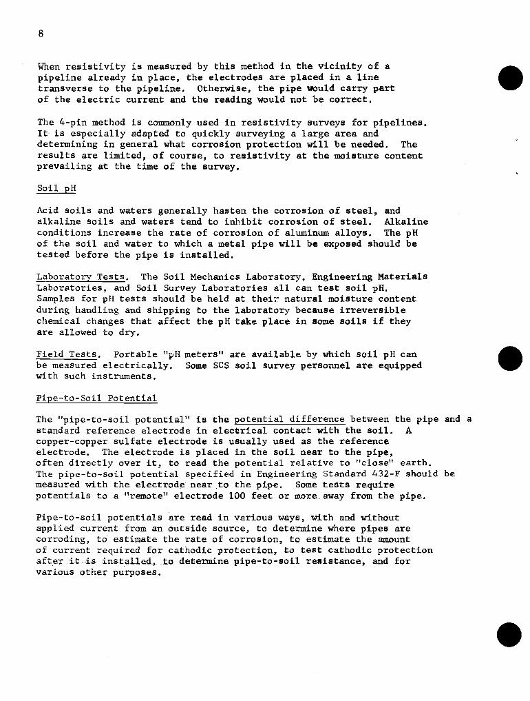
Typical s i n g l e and n u l t i p l c anode i n s t a l l a t i o n s a r e i l l u s t r a t e d i n Figure 3 ; arid a d d i t i o n a l d e t a i l s of anode i n s t a l l a t i o n a r e given i n t h e Appendix, which i s a copy o f Montana job shee t ENG 301 e n t i t l e d " I n s t a l l a t i o n of Galvanic Anodes f o r Corrosion P ro tec t ion of Buried S t e e l P ipe l ines ."
•
•
•
11
Note: Above k values are based on the following assumptions:
1. Steel pipe: -0.85 volt pipe-to-soil potential.
2. Galvanized pipe: -1.15 vol t pipe-to-soil potential.
3. Class B pipe coating, C = 60 (Eng. Standard 432-F).
4. Surface area of pipe exposed to soil - l2~0. sq. ft.
5. Anodes are "packaged" or bedded in chemical backfill;e.g., gypsum and bentonite.
Higher k values are applh:able when the pipe to be protected ispoorly insulated from the soil. For example, if C is 120 instead of60, other conditions being the same, the corresponding k is 20 to 40percent higher than given in the table. For bare pipe, anode kvalues are roughly twice those in the table.
Anode Life
Magnesium anodes are consumed at the rate of about 17 pounds peryear per ampere delivered, ard zinc anodes at the rate of about26 pounds per year per an~ere. Since anodes can be expected to stopfunctioning before they are completely consumed, a "utilizationfactor" of 0.75 to 0.85 'Usually is applied in calculating anode life.The formulas for anode life in Engineering Standard 432-F includea utilization factor of 0.80.
1\110<1(', Install/ition
Typical single and multiple anode installations are illustrated inFigure 3; and additional details of anode installation are givenin the Appendix, which is a copy of Montana job sheet ENG 301entitled "Installation of Galvanic Anodes for Corrosion Protectionof Buried Steel Pipelines."
Powder-weld Test station
connection Insulated wire
Single Anode Installation
Test station
Insulated connect ions Powder-weld Insulated eonneci;ion -coated
Anodes P i p e
for magnesium 10' m i n .
wire
Fig. 3 - Typical Anode InstalPations
12
Powder-weldconnection
-coated
Pipe
5' min.
for magnesium
Test station
Insulated wire
•
Single Anode Installation
•Powder-weldconnection-coated
Pipe -U!
::; W om" ~ -i~.---'"""!I·J ......:.. •
for magnesium
Test station
Insulated connectionsInsulated wire
Anodes
II-10' min.
Multiple Anode Installation
3 - Typical Anode Installations
•

The cu r ren t t h a t can flow from an anode depends l a r g e l y upon t h e r e s i s t i v i t y of t h e m a t e r i a l around i t . Therefore, i t i s important t h a t anodes be i n s t a l l e d where t h e s o i l i s moist and be b a c k f i l l e d wi th t h e lowest r e s i s t t v i t y m a t e r i a l ob ta inable . General ly , "packaged" anodes should be used, i n which t h e magnesium o r z inc ba r s a r e prepackaged i n a uniform chemical b a c k f i l l o f low r e s i s t i v i t y . Ear th b a c k f i l l should be f i rmly compacted around t h e packaged anode. I f packaged anodes a r e not a v a i l a b l e , ba re modes can be i n s t a l l e d i n d r i l l e d holes about 8 inches i n diameter and b a c k f i l l e d wi th a mix tu re& gypsum and b e n t o n i t e i n about equal propor t ions.
Anodes can be i n s t a l l e d v e r t i c a l l y o r ho r i zon ta l ly . This may be governed by s o i l s t r a t a , moisture condi t ions o r o t h e r f a c t o r s . 'hen two o r more anodes a r e used, they should be spaced a t l e a s t 10 f e e t a p a r t . Two o r more anodes connected t o a p ipe at one l o c a t i o n can be s t rung out i n a l i n e perpendicular o r p a r a l l e l t o t h e p ipe c e n t e r l i n e and connected t o a s i n g l e header wire . The i d e a i s t o o b t a i n uniform d i s t r i b u t i o n along t h e p i p e of t h e cu r r en t passing through t h e s o i l from t h e anodes. The c l o s e s t anodes should be not l e s s than about 5 f e e t from t h e pipe. This i s more c r i t i c a l f o r ~ a g n e s i u m than f o r z inc anodes.
Connection between t h e p ipe and t h e anodes should be made wi th i n s u l a t e d copper wire , #8 AWG o r l a r g e r . Copper w i re can be fas tened t o s t e e l o r galvanized p i p e by braz ing o r by t h e powder- weld ( thermi t ) p rocess . Pipe coa t ing damaged i n t h e process should be r epa i r ed , and exposed wi re and weld metal should be coated, Local cor ros ion of t h e p i p e ad jacent t o t h e copper w i re may t a k e p l ace i f t h e whole connection i s no t thoroughly coated t o exclude moisture. Wire s p l i c e s can be made wi th s p l i t - b o l t connectors o r by powder-welding o r brazing, and must be taped o r o therwise in su la t ed .
Bonding
Unless t h e p i p e j o i n t s a r e e l e c t r i c a l l y cont inuora, such a s welded j o i n t s , t h e p ipe s e c t i o n s and couplings i f any must be e l e c t r i c a l l y bonded toge the r t o permit cu r r en t t o flow from t h e anodes t o a l l p a r t s t o be p ro t ec t ed . I f metal an t i - s eep c o l l a r s a r e used, they a l s o should be bonded t o t h e pipe. Bonding may be' accomplished wi th V6 AWG i n s u l a t e d copper wire brazed o r powder-welded t o t h e p ipe , Stranded wire may be p r e f e r a b l e t o s o l i d w i re i f f l e x i b i l i t y i s needed. The i n s u l a t i o n should have a t l e a s t a 600-volt r a t i n g , and must be tough and waterproof . PVC and polye thylene i n s u l a t i o n designed f o r d i r e c t b u r i a l a r e s a t i s f a c t o r y . A s wi th o t h e r connect ions t o t h e p ipe ,
•
•
•
13
The current that can flow from an anode depends largely upon theresistivity of the material around it. Therefore, it is importantthat anodes be installed where the soil is moist and be backfilledwith the lowest resistivity material obtainable. Generally,"packaged" anodes should be used, in which the magnesium or zincbars are prepackaged in a uniform chemical backfill of lowresistivity. Earth backfill should be Hrmly compacted around thepackaged anode. If packaged anodes are not available, bare anodescan be installed in drilled holes about 8 inches in diameter andbackfilled with a mixture of gypsum and bentonite in about equalproportions.
Anodes can be installed vertically or horizontally. This may begoverned by soil strata, moisture conditions or other factors.~en two or more anodes are used, they should be spaced at least10 feet apart. Two or more anodes connected to a pipe at onelocation can be strung out in a line perpendicular or parallel tothe pipe centerline and connected to a single header wire. Theidea is to obtain uniform distribution along the pipe of the currentpassing through the soil from the anodes. The closest anodes shouldbe not less than about 5 feet from the pipe. This is more criticalfor magnesium than for zinc anodes.
Connection between the pipe and the anodes should be made withinsulated copper wire, #8 AWG or larger. Copper wire can befastened to steel or galvanized pipe by brazing or by the powderweld (thermit) process. Pipe coating damaged in the process shouldbe repaired, and exposed wire and weld metal should be coated.Local corrosion of the pipe adjacent to the copper wire may takeplace if the whole connection is not thoroughly coated to excludemoisture. Wire splices can be made with split-bolt connectors orby powder-welding or brazing, and must be taped or otherwiseinsulated.
Bonding
Unless the pipe joints are electrically continuo\;.B, such as weldedjoints, the pipe sections and couplings if any must be electricallybonded together to permit current to flow from the anodes to allparts to be protected. If metal anti-seep collars are used, theyalso should be bonded to the pipe. Bonding may be' accomplished with#6 AWG insulated copper wire brazed or powder-welded to the pipe.Stranded wire may be preferable to solid wire if flexibility is needed.The insulation should have at least a 600-volt rating, and must betough and waterproof. PVC and polyethylene insulation designed fordirect burial are satisfactory. As with other connections to the pipe,
t h e connections should be coated and p ipe coa t ing damaged i n t h e process should be repa i red .
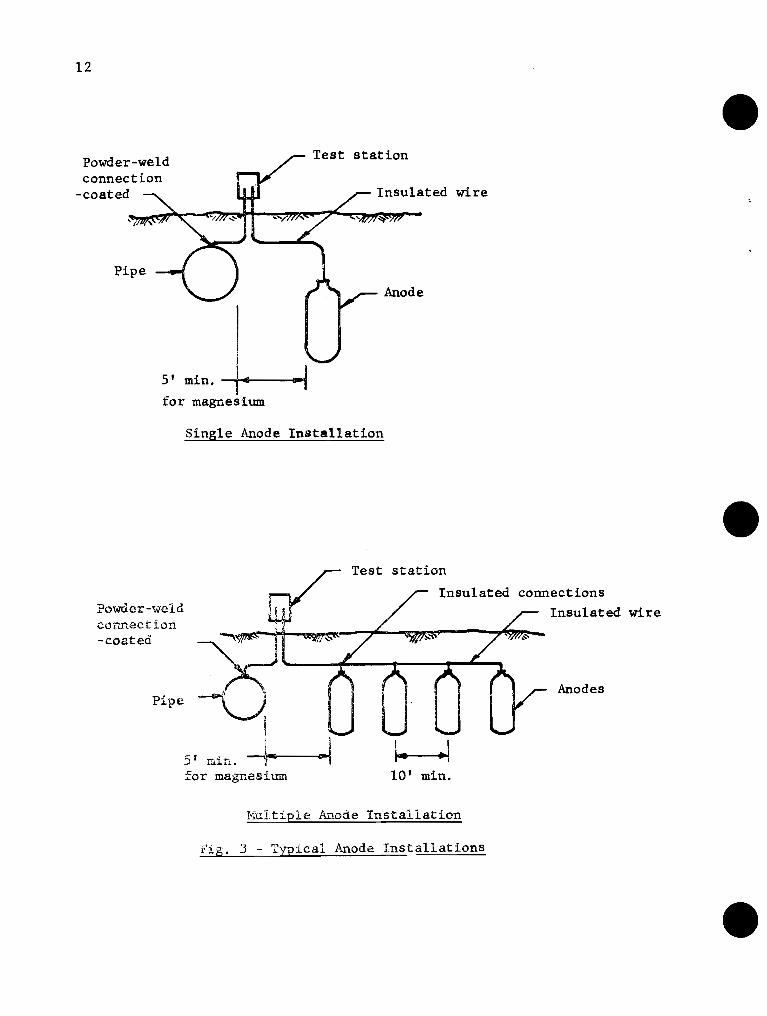
Tes t S t a t i o n s
Each anode i n s t a l l a t i o n , cons i s t i ng o f an anode o r group of anodes connected t o t h e p ipe a t a s i n g l e p o i n t , must be provided with a means of checking t h e anode c u r r e n t , t h e p i p e - t o - s o i l p o t e n t i a l , and t h e anode- to-so i l p o t e n t i a l .
A simple way o f doing t h i s i s t o br ing t h e wire from t h e anodes and t h e wire from t h e p ipe both i n t o a common junc t ion box above ground a t an a c c e s s i b l e l o c a t i o n nea r t h e pipe. This arrangement i s i l l u s t r a t e d i n F igure 4. I n opera t ion , t h e two wires a r e joined with a s p l i t - b o l t connector and taped. For t e s t i n g , t h e t a p e i s removed and t h e wlres a r e disconnected. The wires should be cleaned and fas tened toge the r s ecu re ly each tune they a r e reconnected and t h e whole s p l l c e should be thoroughly sea led wi th rubber o r p l a s t i c tape . O themise , a high r e s i s t a n c e can develop i n t h e connection as a r e s u l t o f co r ros ion o f t h e wires .
f Post - Weatherproof junc t ion box
Wire from p ipe
connection w a t e r t i g h t
Connector - t o be taped
Anode wire
Wire i n conduf t above ground
Fig. 4 - Test S t a t i o n D e t a i l
14
the connections should be coated and pipe coating damaged in theprocess should be repaired.
Test Stations
Each anode installation, consisting of an anode or group ofanodes connected to the pipe at a single point, must be providedwith a means of checking the anode current, the pipe-to-soilpotential, and the anode-to-soil potential.
A simple way of doing this is to bring the wire from the anodesand the wire from the pipe both into a common junction box aboveground at an accessible location near the pipe. This arrangementis illustrated in Figure 4. In operation, the two wires arejoined with a split-bolt connector and taped. For testing, thetape is removed and the wires are disconnected. The wires shouldbe cleaned and fastened together securely each time they arerecoIULected and the whole spl~ce should be thoroughly sealed withrubber or plastic tape. Otherwise, a high resistance can developin the connection as a result of corrosion of the wires.
Post
Weatherproofjunction box
pipe
Connector - connectionto be taped watertight
Anode wire
Wire in conduitabove ground
Fig. 4 - Test Station Detail
•
•
•

The ca thodic p r o t e c t i o n cu r r en t i s measured by connecting a m i l l i m e t e r between t h e wi re from t h e anodes and t h e wi re from t h e p ipe . P ipe - to - so i l p o t e n t i a l , wi th and without t h e anodes connected, i s measured by a t t ach ing t h e t e s t l ead from t h e copper-copper s u l f a t e e l e c t r o d e t o t h e wire from t h e p ipe , wi th and without t h e anode wire connected. Anode p o t e n t i a l i s measured by a t t ach ing t h e t e s t l ead t o t h e wi re from t h e anodes.
Figure 2 i n t h e Appendix shows a s l i g h t l y more e l a b o r a t e t e s t s t a t i o n us ing a switch and p lug- in receptacle. The anode-to-pipe c i r c u i t can be turned on o r o f f by t h e switch, and t h e t e s t equipment i s designed so t h a t i t can be simply plugged i n t o t h e r ecep tac l e f o r t e s t i n g .
Adjustment of Current
I f t h e anodes changethepipe- to-so i l p o t e n t i a l more than necessary f o r adequate p r o t e c t i o n , t h e anode cu r ren t can be l i m i t e d by i n s t a l l i n g a r e s i s t o r i n t h e c i r c u i t . It may be connected between t h e two wires i n t h e t e s t box descr ibed above. The o b j e c t i s t o extend t h e l i f e of t h e anodes. I f t h e anodes do n o t change t h e p i p e - t o - s o i l p o t e n t i a l enough, i t may be necessary t o add more anodes.
Maintenance
Cathodic p r o t e c t i o n i n s t a l l a t i o n s should be inspec ted and t e s t e d a t l e a s t on:e a year . S o i l mois ture and r e s i s t i v i t y change, e s p e c i a l l y where n a t u r a l condi t ions a r e a l t e r e d by a dam o r o t h e r s t r u c t u r e ; p i p e coa t ings d e t e r i o r a t e ; anode and cathode su r f aces change chemical ly; and o t h e r changes t a k e p l ace which can i n f luence t h e behavior of t h e ca thodic p r o t e c t i o n c i r c u i t . The p ipe should be inspec ted f o r s igns of cor ros ion , a l s o . Anodes should be replaced when they s top provid ing t h e necessary p ro t ec t ion .
INSTRUMENTS
Some of t h e instruments t h a t a r e a v a i l a b l e a r e descr ibed below with t h e i r approximate p r i c e s .
For s o i l r e s i s t i v i t y
So i l cup - Beckman Model CEL-M. Avai lable from Beckman, American Instrument , S o i l t e s t and o the r s . @ $65+_ (Used with conduct iv i ty br idge . )
• The cathodic protection current is measured by connecting amilliammeter between the wire from the anodes and the wire fromthe pipe. Pipe-to-soil potential, with and without the anodesconnected, is measured by attaching the test lead from thecopper-copper sulfate electrode to the wire from the pipe, withand without the anode wire connected. Anode potential is measuredby attaching the test lead to the wire from the anodes.
15
Figure 2 in the Appendix shows a slightly morestation using a switch and plug-in recEptacle.circuit can be turned on or off by the switch,equipment is designed so that it can be simplyreceptacle for testing.
Adjustment of Current
elaborate testThe anode-to-pipe
and the testplugged into the
•
•
If the anodes change the pipe-to-soil potential more than necessaryfor adequate protection, the anode current can be limited byinstalling a resistor in the circuit. It may be connected betweenthe two wires in the test box described above. The object is to~~tend the life of the anodes. If the anodes do not change thepipe-to-soil potential enough, it may be necessary to add moreanodes.
Maintenance
Cathodic protection installations should be inspected and testedat least on2e a year. Soil moisture and resistivity change,especially where natural conditions are altered by a dam or otherstructure; pipe coatings deteriorate; anode and cathode surfaceschange chemically; and other changes take place which caninfluence the behavior of the cathodic protection circuit. Thepipe should be inspected for signs of corrosion, also. Anodesshould be replaced wh.-m they stop providing the necessaryprotection.
INSTRUMENTS
Some of the instruments that are available are described belowwith their approximate prices.
For soil resistivity
Soil cup - Beckman Model CEL-M. Available from Beckman,American Instrument, Soiltest and others. @ $6S± .(Used with conductivity bridge.)

Soil box - I?$' x 2%" x 9" plexiglass soil box available from M. C. Miller Co., 288 East Saddle River Road, Upper Saddle River, 8. J. @ $17t . (Used with Vibroground or similar combin;ition instrument, or with milliammeter and high resistance millivoltmeter or potentiometer.)
Conductivity bridge - Beckman Model RC-7. Portable, battery operated. Available from Beckman Instrument CO., Cedargrove, N. J.; American Instrument Co., 17 Pollock Avenue, Jersey City, N. J. @ $3555 . Conductivity bridge - Beckman Model RC-19. New light-weight, battery or line operated. Available from Beckman Instrument Co. @ $5955
Single-probe instrument - Available from Associated Research, Inc., 3758 West Belmont Avenue, Chicago; Agra Engineering Co. 4 551 South Quaker Avenue, Tulsa, Oklahoma, and others. @ $125- (Used with Vibroground or other bridge.)
Four-pin resistivity instrument - Vibroground Model 293. Battery operated, with steel case, 4 T-shaped ground probes, and test leads. Available from Associated Research, Inc., 3758 West Belmont Avenue, Chicago. @ $375$- .
For soil pH.
Pocket ?H meter - Beckman. Portable, battery operated, sturdy con'bination electrode. Available from Beclcman or any of their dealers: Chicago Apparatus Co., 1735 North Ashland Avenue, Chicago. @ $952
For p i p e - t o - s o i l potentiai, cathodic protection tests, etc.
Combination current and voltage meter. Available from M. C. Miller, Agra Engineering, and others. @ $225? . High resistance voltmeter or potentiometer. Available from M. C. Miller, Agra Engineering, and others. @ $80-2105 . Portable volt-ohm-milliammeter for pipe continuity checks. Available from Simpson Electric Co. or Triplett Electrical Instrument Co. @ $70? . Current interrupter. Available from M. C. Miller, Agra Engineering, and others. @ $165?
Copper-copper sulfate electrode. Available from M. C. Miller, Agra Engineering, and others. @ $15? .
16
Soil box - l~" x 2~" x 9" plexiglass soil box availablefrom M. C. Miller Co., 288 East Saddle River Road, UpperSaddle River, N: J. @ $l7±. (Used with Vibroground orsimilar combination instrument, or with milliammeter andhigh resistance millivoltmeter or potentiometer.)
Conductivity bridge - Beckman Model RC-7. Portable,battery operated. Available from Beckman Instrument Co.,Cedargrove, N. J.; American Instrument Co., 17 PollockAvenue, Jersey City, N. J. @ $355± •
Conductivity bridge - Beckman Model RC-19. New light-weight,battery or line operated. Available from Beckman InstrumentCo. @ $595± .
Single-probe instrument - Available from Associated Research,Inc., 3758 West Belmont Avenue, Chicago; Agra Engineering Co.+551 South Quaker Avenue, Tulsa, Oklahoma, and others. @ $125(Used with Vibroground or other bridge.)
Four-pin resistivity instrument - Vibroground Model 293.Battery operated, with steel case, 4 T-shaped ground probes,and test leads. Available from Associated Research, Inc.,3758 West Belmont Avenue, Chicago. @ $375~ .
For soil pH.
Pocket ~H meter - Beckman. Portable, battery operated, sturdycombination electrode. Available from Beckman or any of theirdealers: Chicago Apparatus Co., 1735 North Ashland Avenue,Chicago. @ $95± •
For pipe-to-soil potential, cathodic protection tests, etc.
Combination current and voltage meter. Available from M. C. Miller,Agra Engineering, and others. @ $225± .
High resistance voltmeter or potentiometer. Available from M. C.Miller, Agra Engine2ring, and others. @ $80-210± •
Portable volt-ohm-milliammeter for pipe continuity checks.Available from Simpson Electric Co. or Triplett ElectricalInstrument Co. @ $70± •
Current interrupter. Available from M. C. Miller, AgraEngineering, and others. @ $165± •
Copper-copper sulfate electrode. Available from M. C. Miller,Agra Engineering, and others. @ $lS± •
•
•
•
REFERENCES
Peabody, A. W. "Control of Pipeline Corro sf-on, I' National Association of Corrosion Engineers, 192 pp., 1967.
Romanof f , M. "Underground Corrosion, I' National Bureau of Standards, 227 pp., 1957.
Engineering Standard 432-F. Irrigation Pipeline, Steel, SCS National Engineering Handbook, Section 2, 1969.
Engineering Memorandum-27, Earth Dams, Section E, Principal Spillways, 1969.
•
•
•
17
REFERENCES
Peabody, A. W. "Control of Pipeline Corros~~on," National Associationof Corrosion Engineers, 192 pp., 1967.
Romanoff, M. "Underground Corrosion," National Bureau of Standards,227 pp., 1957.
Engineering Standard 432-F. Irrigation Pipeline, Steel, SCS NationalEngineering Handbook, Section 2, 1969.
Engineering Memorandum-27, Earth Dams, Section E, Principal Spillways,1969 •

•
•
•

APPENDIX
INSTALLATION FOX CORROSION
OF GALVANIC ANODES PROrI'ECTIOM OF BURIED
STEEL PIPELINES The propcr i n s t a l l a t i o n of anodes i s the key t o t h e con t inu ing p ro t ec - t i o n fcom co r ros ion o f R bur i ed s t e e l p i p e l i n e . An improperly i n s t a l l e d and maintained anode can j n c r e a s e t h e r e s i s t i v i t y o f t h e s o i l surround- i n g i t and r e s u l t i n an underpro tec ted p i p c l i n e t l ~ o s dec reas ing t h e m a b l e l i f e o f the l i n e .
Anodes may ht? placed e i t h e r h o r i z o n t a l l y o r v e r t i c a l . l y i n r e l a t i o n to thc ~ i o t ' n d surface m d i n r e l a t i o n t o t h e p i p c l i n e e i t h e r p a r a l l e l o r pcrpenrlicul. ir , s e e FCgure 1. When plnccd h o r i z o n t a l l y , 1-hey s h a l l be r l t or b c l o u t.i:e bottoru e l e v a t i o n o f the p i p e l i n e . ITever p lnc? anodes I i l l n t r i l V e r t i c a l l y p laced anod~-+s s l ~ i l l h l v e a rn in i~~urr . J is - ~ 1 1 1 2 ~ of 3 i ~ c t betxcen the gzound s u r h c e and the t op of thc 'inode.
L o c ~ t i o n of the anodes i n r e l a t i o n t o t he p i p e l i n e i s no t c r i t i c a l c:,r:cp': i n the case of rna&ncsium 1d:ich nus t be p laced a m i n i m m d i s - t,:occ: of 10 f o c t f x c m t he p i p e l i n e .
1. I.:xcavatc itole o r t r e n c h for m o d s packa.ge.
: 3 . Pl.;,~ce ,I:-.c:.k pr;clc,?ge i n t he prep.,:rtd bed rca!ting s u r e that t h c imodc i s cr.nti?r:?d i n tlkc p z c k g c . Use e x t r c n ? c a u t i o n n o t t o get the a.nor!c p.:c!c:?za :;cC beEor-2 i t i s placed and 'oackLilled. :&?v?-r L i f t ----- t:i:: : : ~ t i i : t by the Lead wire .
•
•
•
APPENDIX 1
l;l'-JS -r:r.G 301
Il\JS11 ALLA'rION OF GJ-\LVA}JIC ANODESl?Oll C()RROSIOt~ PR011~~CTIOl\T OF' BURIEDsrrE~EL PIPIGLINES
The proper in~tallation of anod~s is the key to the continuing protection from corrosion of a buried steel pipeline. An improperly installedand maintained anode can increa3e the resistivity of the soil surrounding i~ and result in' an underprotected pipeline thus decreasing theusable life of the line.
Anode Installation
Anodes may he placed either horizontally or vertically in l"elation tothe Gi"ound surf.Jce .:'.ud in relation to the pipcU.ne cith~r parallel orpe rpendicular, Gce Figure 1. \-lhen placed horizontally, they shall beat or beloY tile bottom elevation of the pipeline. Never plac.:! aaodesin fill material. Vertitally placed anoden 9~lll have a minimum Jislan.,::c of 3 f~ct betNccn the ground surface and the top of the anode.
Location of the anodes in relation to the pipeline is not criticale;~ccptin the cC\se of magncshllu ~"hi.ch mus t be placed a minimum distance of 10 feet frem the pipeline.
1. Excavate hole or trench for anodz packa.ljc.
2. Pl"'~p".'I:·e h,~,1ding for the anode p,J.ckage in the bottom of the hole or::i.·cnch~ri.th Hell tamped moL:-,t clayey silt.
:3. Pl.ar.e ;::-.oJc pc.cka·ze in thp. pi:'ep,;tr~d bed m~kin8 sure that the anodeis ccntcr:2d in the pack..'l3~. U'3e extrem3 cautlon not ':0 get theano~~ p~ckn3e ~ct before it is placed and backfilled. NaV2r liftth2 ;a:or~.J '.;y the lead wire. -----
!~. C·~··l}h:i.•~ b'..ckfilH.ng ~ro'.!nd mwdc pith t;ell ta·C!;.ed clayey silt toa puiut 6 iuche~ above tho anode, see Figure 1.
5. t.tI:i\,;h ;;.ill.:~ le;:J ('lire to ::h.3 .)ipcliw~ by ~)l'(lzh13 o't" (;I::<~·,!(d.d l,::ddllgS'l·.'e th,t i.:.k; pipe coating r~r;\rrr1cl i:3 r •.:pail.'cd. ~lhp.n the nnod;~ ist:o be ilU::.c.d1"ld to a t2:,J;i'.l3 :,taf:;.ou, at:t<lCil ~.S ,~1:m1ll 111 Figul'C 2.
6. [;:..·i;y,te tl.-n anode by rOU::.:1.dg :3,~vcr[l.1 bl.l.Tels of i{;lr-.,~r ill the holeor :; ..·.:::lc11 ;md J.el~ soak in i:() i',Sll~C mol:; tcnl ..g of tbe m"')d~ F.\eka~:;d L<~,:kfi.ll.
1. Cociplct'J h.:.(:k.fill ·T:U.:.h native .100::; lc~ving Ii 6 inch sm:faGe d~~p
cc,~c;j.()n ;";,J shm'l1 '\.11 Fij:''.lr~ 1.

APPENDIX 2
When anodes a r c p l aced i n t i g h t n a t i v e c l a y s , some p r o v i s i o n must be made t o i n s u r e continued i r r i g a t i o n o f t h e anode. Th i s can be accorn- p l i s h e d w i t h a sandy g r a v e l "French d ra in" . If t h e anode i s i n a v e r t i c n l h o l e , t h e nat ive backKi l l call be r cp l accd w i t h a sandy g r d v e l b a c k f i l l . Glherc t h c enode i s p laced i n a h o r i z o n t a l p o s i t i o u , t h i s procedure cannot be uscd as a g r a v e l backfi.11 above the anode would reduce t h e c u r r e n t o u t p u t 30 t o 50 p e r c e n t . In t h i s c a s e , a t one end o f t h e anode b a c k f i l l n t r e n c h w i t h s s x i y g r a v e l from anode dep th t o the s u r c a c e o f t h ? ground. The t r e n c h l e n g t h should ex tend away froin t h e anoze 2 t o 3 tirccs t h e & p t h of ~ h c anodc.
-- After anode is ~ ~ e l l soaked backfill to ground surfoce.
node - place a t or
HORIZONTAL Iil lSTALLATlON
After anode is well soaked backfill to ground surface.
VERTICAL INSTALLATION
FIG. I
APPENDIX 2
MT-JS-ENG 301
When anodes arc pl~ccd in tight native clays, some ptovision must bemade to insure continued irri8&tion of the anode. This can be aCCOln
plished with a sandy gravel "French drain l'. If the anode is in a
vertical hole, the native backfill can be replaced with a sandy gravelbackfill. Where the enode is placed in a horizontal position, thisprocedure cannot be uSEd as a gravel backfill above the anode wouldreduce the current output 30 to 50 percent. In this case, at one endof the anode backfill 8 trench with sandy grQvel from anode depth tothe su.rface of th::! ground. The trench length should extend awJ.y fromthe anode 2 to 3 times the depth of the anode.
•
•
Groundsurface
Steelpipeline
Irrigationriser
After anode is well soa!(edbackfill to ground surface.
HORIZONTAL INSTALLATION
Insulated anode wire. ;~aged anod;-=--p-Ia-c-e-a-t-o-r~~Ql below pipe level - can be~~. either paralell or perpendicular
3 min. to pipeline.
Backfil: of welltampedmoist clayeysilt.
10'-0" minimum for magnesium
?r'~ig~ft~~m~:or~ 1__--~~-no7tn~~ical,,~~~ Zi~C>", 0 I
Groundsurfaco
Steelpipeline
Irrigationriser
" ,
After anode is well soakedbackfill to ground surface
10'- 0" minimum for magnesium6" depression forl I .. not critical for zinc -----tirrigatil~nolde I4 ~:--~'77-"<"«","«<"(~<-7'.77~~
C ''E .~
=0 =
-~j ~r-/...-:;~_~~__in_SU_la_t_ed_a_n_o_d_e_w_ir_e_--,
~ Packuged anodo
VERTICAL INSTALLATION
FIG. I •

CT
or
qu
cl.
3
Bra
cke
t
wea
ther
p
roo
f bo
y, w
ith
pla
k
and
snap
co
rers
STA
T IO
N
in S
ox
L
.- 111 [L i I
90° c
onne
ctor
-
-
,yo
-
for
7 k
no
c~
ou
t Iu
_I/
\ A
node
w
ire
I o )
I"
C 7 fl
exi
bie
st
eel
con
dl~
it
OU
TLE
T
&
SW
ITC
H
Ano
de
wir
e
FR
Oh
7
VIE
W
Ano
de
wire
IRR
IGA
TIO
N
RIS
ER
W
ITH
A
NO
DE
T
ES
T
BO
X
OU
TL
ET
B
OX
S
IDE
V
IEW
--I C\L
-
No
te:
Wire
co
nnec
tion
s to
be
silv
er
so!d
ered
.
ANODE TEST STATION
wire
Note:
Wire connec tionsto be silversoldered.
OUTLET & SWITCHFRONT VIEW
U-BAR
steel conduit
wire
OUTLET BOXSIDE VIEW
To anode
W'eather proofbox with plateand snap covers.
After welding U-borto riser, wectt'lerploof \f/ith TopecoatC T O( equal.
Anode wire
I T~~n: nS~fOce~ == _ =// /=''='" 90" connector~ '"l-~ for "2 knockout
f
IRRIGATION RISER WITH
ANODE TEST BOX
'Ic:en
.....,
...o<".."~"
..'"'".....-....'"'"'".."
"d
~.
".....".,o...:~n
"

•
•
•

•
•
•

•"
•
•


![[Shahamat U. Khan] Pesticides in the Soil Environm(BookFi.org)](https://static.fdocuments.in/doc/165x107/55cf9cd3550346d033ab2dad/shahamat-u-khan-pesticides-in-the-soil-environmbookfiorg.jpg)