U B Manual032717 - Unified Ind Manual.pdf · SAFETY ALERT SYMBOL AND ALERT SIGNS Please read this...
30
AIR BALANCER WARNING Never use the Air Balancer for lifting or lowering people. Supply this manual to the user. Read this manual before installation, operation or maintenance. Keep this manual available. U_B-Series
Transcript of U B Manual032717 - Unified Ind Manual.pdf · SAFETY ALERT SYMBOL AND ALERT SIGNS Please read this...
AIR BALANCER
WARNING
Never use the Air Balancer for lifting or lowering people.
Supply this manual to the user.
Read this manual before installation, operation or maintenance.
Keep this manual available.
U_B-Series

SAFETY ALERT SYMBOL AND ALERT SIGNS
Please read this manual carefully and follow its instructions.
The SAFETY ALERT SYMBOL( ), WARNING, CAUTION, and NOTE
NOTE NOTE indicates a special instruction in operation or maintenance
CAUTION CAUTION indicates a hazardous situation which,
if not avoided, could result in minor or moderate injury,
damage or destruction or the equipment and others.
WARNING indicates a hazardous situation which, WARNING
if not avoided, could result in death or serious injury.
This SAFETY ALERT SYMBOL is used to call your attention to items or
operations that could be dangerous to you or other persons using this
equipment.
Please read these messages and follow these instructions carefully.

1. Safety Instructions
2. Explanation of the product
Table of Contents ……………………………………..…...1
…………………………………..……...5
3. Checks and Instructions before installation
3.1 Checks of the Product
3.2 Instructions on Working Conditions
4. Installation
4.1 Installation
4.2 Before Air Connection
5. Hoisting and Test Run
5.1 Setting Balancer Speed
5.2 Check of the Lifting Height
5.3 Other Checks
6. Checks before Operation at the beginning of each shift
6.1 Check before startup
6.2 Check by idling Operation
6.3 Check by Load Operation
7. Periodic Inspection
8. Maintenance and Inspection
8.1 Inspection
8.2 Storing the Air Balancer
8.3 Troubleshooting
9. Wire Rope Setup
9.1 Wire Rope Replacement
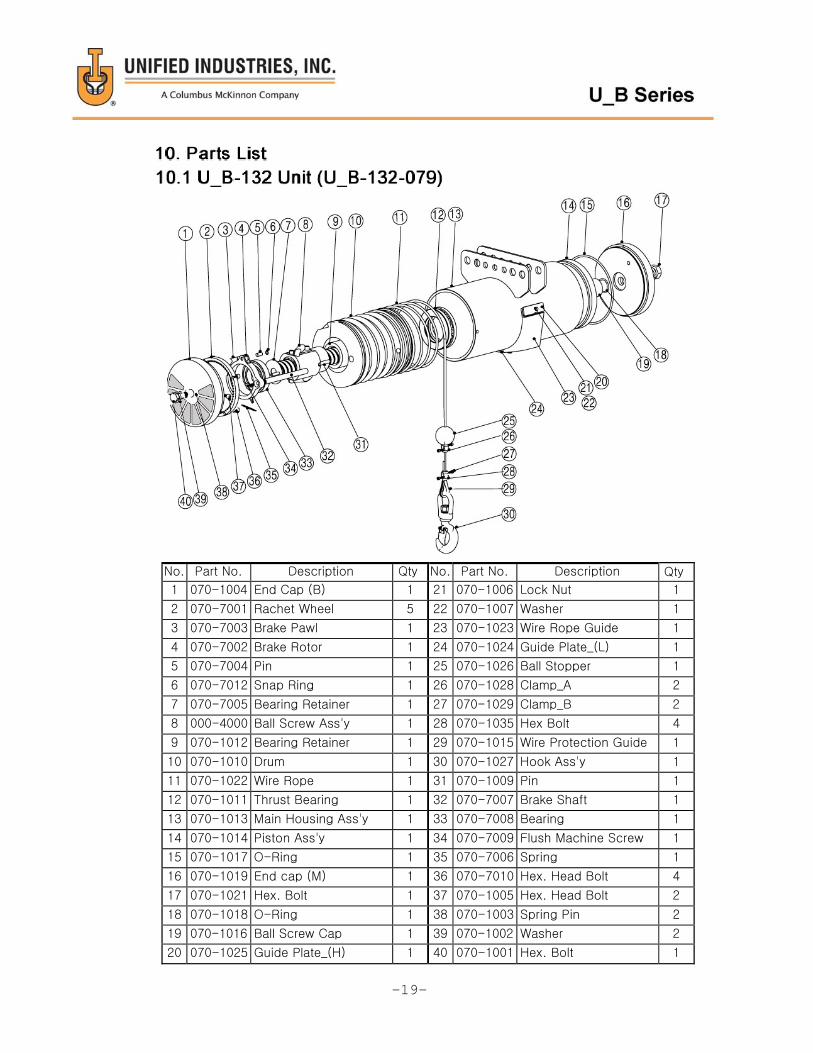
10. Parts List
10.1 U_B-132 Unit (U_B-132-079)
10.2 U_B-220 Unit (U_B-220-118)
10.3 U_B-331 Unit (U_B-331-079)
10.4 U_B-485 Unit (U_B-485-076)
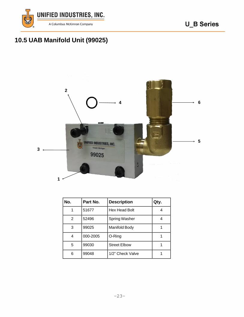
10.5 UAB Manifold Unit (99025)
10.6 Suspension Hook Unit (99100)
10.7 Reeved Hook Unit
10.8 Inspection and Maintenance Sheet
……………………………………..…...6
……………………………………..…...6
……………………………………..…...7
……………………………………..…...7
…………………………………..……...7
…………………………………..……...8
……………………………………….....9
………………………………………9-10
………………………………………...10
………………………………………...10
………………………………………...10
………………………………………...10
………………………………………...11
………………………………………...11
………………………………………...11
………………………………………...12
………………………………….....12-14
………………………………...……....14
………………………………………...15
……………………………..……....16-17
………………………………………...18
………………………………………...19
………………………………………...20
………………………………………...21
………………………………………...22
………………………………………...23
………………………………………...24
………………………………………...25
…………………………………………26

1. Safety Instructions If the Air Balancer is not used correctly a serious accident may occur, such as
dropping the load or the Air Balancer itself. Before installing, operating, controlling, inspecting of Air Balancer, read and understand this instruction manual.
Until understanding of all equipment terminology, safety information, caution and
warning, do not use the Air Balancer .
1.1 General Instructions
1.2 Instructions for safe operation
If there are any differences between instruction manual and the standard of your
company, give the priority to stricter standards from either of both.
1.2.1 General handling
-1-
WARNING - Never operate the Air Balancer unless the contents of this manual and caution plate
(warning label) are completely known. - Never operate the Air Balancer nor sling a load unless you were trained in safety
rules and in operating manner of the Air Balancer.
Never allow untrained persons to do so.
- Never remove or deface any nameplates, caution plates or warning labels,
which are attached to the Air Balancer. - Always check the Air Balancer before each shift, and inspect it periodically.
- Never operate the Air Balancer if you are not physically fit to do so.
The operator must have good hearing, vision and depth perception.
- When any instruction signs put on the push button switches such as
EQUIPMENT BEING INSPECTED or DO NO RUN, never operate the Air Balancer
until the sign is removed by the designated person.
WARNING - Never use the Air Balancer to lift or lower people.
Also never carry the loads over people or around people.
- Before installing, operating, controlling, inspecting of the Air Balancer,
read and understand this instruction manual.
- After reading, keep this manual available for maintenance and inspections.
- Always check the supporting member from which the Air Balancer is suspended is
strong enough to support the weight of the Air Balancer plus the weight of the
maximum capacity, etc.
The customer has the responsibility for this.

1.2.2 Installation
1.2.3 Air Pressure
NOTE: The actual Load Capacity of the balancer is based on plant air pressure and the recommended 80% optimal load capacity. Example: The plant air pressure is 65 psi using 331lb air balancer. Formula as follows: (331lb x 0.65 air supply x .80 optimal load) = 172lb Load Capacity
-2-
CAUTION - Never use the lubricator in air supply line.
Oil will damage internal components. Never use any kind of oil.
- Never operate the Air Balancer without filter and regulator.
WARNING Never set the air pressure over 0.7MPa { 7kgf /cm2, 100psi }.
If it is necessary, reduce and set the air pressure to the requirement of working
air pressure.
CAUTION Never operate the Air Balancer when it is placed on the floor.
Never operate the Air Balancer with the slackened wire rope.
Only operate the Air Balancer when it is hanging.
WARNING - Always employ specialists or well-trained persons for installation.
- Never install the Air Balancer in any environments, which is out of specifications.
For example, the Air Balancer should not be exposed to rain or water.
- Always install stoppers at the end of the rails for traveling or traversing.
- Always check the supporting member for the Air Balancer has enough strength.
- Make the Air Balancer able to swing freely by using the Suspension hook or
the fitting. * Never fix the Air Balancer.
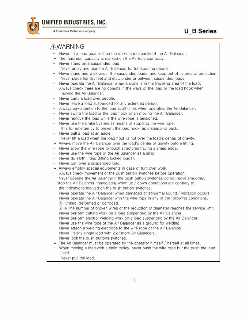
WARNING - Never lift a load greater than the maximum capacity of the Air Balancer.
* The maximum capacity is marked on the Air Balancer body.
- Never stand on a suspended load.
Never apply and use the Air Balancer for transporting people.
- Never stand and walk under the suspended loads, and keep out of its area of projection.
Never place hands, feet and etc., under or between suspended loads.
- Never operate the Air Balancer when anyone is in the traveling area of the load.
- Always check there are no objects in the ways of the load or the load hook when
moving the Air Balancer.
- Never carry a load over people.
- Never leave a load suspended for any extended period.
- Always pay attention to the load at all times when operating the Air Balancer.
- Never swing the load or the load hook when moving the Air Balancer.
- Never remove the load while the wire rope is tensioned.
- Never use the Brake System as means of stopping the wire rope.
It is for emergency to prevent the load hook rapid snapping back.
- Never pull a load at an angle.
Never lift a load when the load hook is not over the load's center of gravity.
* Always move the Air Balancer over the load's center of gravity before lifting.
- Never allow the wire rope to touch structures having a sharp edge.
- Never use the wire rope of the Air Balancer as a sling.
- Never do earth lifting (lifting locked loads).
- Never turn over a suspended load.
* Always employ special equipments in case of turn over work.
- Always check movement of the push button switches before operation.
Never operate the Air Balancer if the push button switches do not move smoothly. - Stop the Air Balancer immediately when up / down operations are contrary to
the indications marked on the push button switches.
- Never operate the Air Balancer when damaged or abnormal sound / vibration occurs.
- Never operate the Air Balancer with the wire rope in any of the following conditions.
① Kinked, deformed or corroded.
② A The number of broken wires or the reduction of diameter reaches the service limit.
- Never perform cutting work on a load suspended by the Air Balancer.
- Never perform electro-welding work on a load suspended by the Air Balancer.
- Never use the wire rope of the Air Balancer as a ground for welding.
- Never attach a welding electrode to the wire rope of the Air Balancer.
- Never lift any single load with 2 or more Air Balancers.
- Never lock the push buttons switches.
* The Air Balancer must be operated by the operator himself / herself at all times. - When moving a load with a plain trolley, never push the wire rope but the push the load
itself.
Never pull the load.
-3-

1.2.4 Operation and Handling
1.2.5 Maintenance, Inspection and Alterations
-4-
WARNING
- Never alter the Air Balancers or its accessories.
- Always use genuine parts for replacement.
- Always shut off the air supply before carrying out maintenance, inspection or repair.
- Always employ specialists or well trained persons for maintenance, inspection and
repair.
- Always remove the load from the Air Balancer before maintenance, inspection or
repair. - Always disassemble the Air Balancer on the floor.
- If any problems are detected during maintenance or inspection, never use the
Air Balancer but correct and repair the problems immediately.
- Periodically, inspect the Air Balancer thoroughly and replace any worn or damaged
parts.
- Stretched, worn or damaged hooks should be discarded.
Never attempt to repair it, just replace it with a new hook. - Always put up an instruction sign ("EQUIPMENT BEING INSPECTED",
"DO NOT OPEN THE VALUE", etc.) before carrying out maintenance, inspection or
repair.
- Never do anything if you have any questions about the Air Balancer, please do not
hesitate to contact you dealer or us.
CAUTION
- Never use the hook with a damaged or malfunctioning hook latch.
- Always operate the Air Balancer carefully during lifting and lowering operations.
Never start, stop or reverse the Air Balancer suddenly.
- Never allow the suspended load to touch the nearby structure or power lines, etc.
- Never jerk the hose of the push button switches nor catch it on the nearby structure.
- Never allow the Air Balancer or trolley to collide with the I-beam stopper or the
structure.
- Always check the load hook can swivel smoothly before operating the Air Balancer.
- Always position the slings at the center or the load hook.
- When starting to lift, stop the Air Balancer once as the wire rope becomes
tensioned. * Never jerk the Air Balancer. Carefully take up the slackened wire rope.
- Always check the load-lifting height of the Air Balancer is enough for required work.

2. Explanation of the product
2.1 Specification
● Single Wire Rope Units(Air Pressure 7kgf/cm2)
Model Capacity Lift Dia.×L(B)of Body H Net Weight
kg lbs mm in mm in mm in kg lbs
U_B-132-079 60 132 2000 79 155×392 6.1×15.43 600 23 23 51
U_B-220-118 100 220 3000 118 260×400 10.24×15.75 700 28 42.5 94
U_B-331-079 150 331 2000 79 260×400 10.24×15.75 700 28 47 105
U_B-485-079 230 485 1950 79 310×400 12.21×15.75 750 30 50 110
● Wire Rope Units(Air Pressure 7kgf/cm2)
Model Capacity Lift Dia.×L(B)of Body H Net Weight
kg lbs mm in mm in mm in kg lbs
U_B-440-59R 200 441 1500 59 260×400 10.24×15.75 700 28 47 104
U_B-440-118T 200 441 3000 118 2-260×400 10.24×15.75 700 28 92 203
U_B-662-39R 300 661 1000 39 260×400 10.24×15.75 700 28 45 99
U_B-661-79T 300 661 2000 78 2-260×400 10.24×15.75 700 28 90 198
U_B-970-39R 440 970 1000 38 310×400 12.21×15.75 750 30 56 124
U_B-970-79T 440 970 2000 76 2-310×400 12.21×15.75 750 30 110 243
U_B-882-59TR 400 882 1500 59 2-260×400 10.24×15.75 700 28 95 209
U_B-1323-39TR 600 1323 1000 39 2-260×400 10.24×15.75 700 28 92 203
U_B-1940-39TR 880 1940 1000 39 2-310×400 12.21×15.75 750 30 115 254
The Plug for 3/8" coupler is provided at the air supply inlet.
■ Working conditions
- Application area : Indoor and normal atmospheric conditions
- Temperature range : -10℃ to +50℃
-5-
CAUTION - Follow the lubrication instructions.
- Never operate the Air Balancer without regulator and filter.(Never use lubricator)
- Always hang the Air Balancer when carrying out test run after maintenance
or repair.
* Never operate the Air Balancer with the slackened wire rope.
Never operate the Air Balancer when it is placed on the floor.
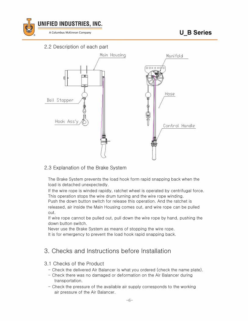
2.2 Description of each part
2.3 Explanation of the Brake System
The Brake System prevents the load hook form rapid snapping back when the
load is detached unexpectedly.
If the wire rope is winded rapidly, ratchet wheel is operated by centrifugal force.
This operation stops the wire drum turning and the wire rope winding. Push the down button switch for release this operation. And the ratchet is
released, air inside the Main Housing comes out, and wire rope can be pulled
out.
If wire rope cannot be pulled out, pull down the wire rope by hand, pushing the
down button switch.
Never use the Brake System as means of stopping the wire rope.
It is for emergency to prevent the load hook rapid snapping back.
3. Checks and Instructions before Installation
3.1 Checks of the Product - Check the delivered Air Balancer is what you ordered (check the name plate).
- Check there was no damaged or deformation on the Air Balancer during
transportation.
- Check the pressure of the available air supply corresponds to the working
air pressure of the Air Balancer.
-6-
3.2 Instructions on Working Conditions
4. Installation
4.1 Installation
Make certain the Air Balancer is properly installed. A little extra time and effort in doing so can contribute a lot toward preventing
accidents and helping you get the best service possible.
The supporting member for the Air Balancer should have successfully passed an
Inspection for the applicable safety standard.
- Check the suspension hook is correctly rigged onto the supporting member
and the hook latch is correctly closed. - Never use a supporting member that suspends the Air Balancer at an angle.
-7-
CAUTION
Never operate the Air Balancer when it is placed on the floor (never lay it down).
Only operate the Air Balancer when it is hanging.
WARNING Always check the supporting member from which the Air Balancer is suspended is
strong enough to support the weight of the Air Balancer plus the weight of the maximum capacity, etc.
The customer has responsibility for this.
CAUTION - Do not install and leave the Air Balancer outdoors.
If it is necessary to use the Air Balancer outdoors, always make a shelter with
a roof for housing the Air Balancer.
- Under hostile environments such as high temperatures, high humidity, acidic,
corrosive and / or extremely dusty atmospheric conditions, the
mechanical parts of the Air Balancer may be seriously damaged
(for example, corroded). Therefore, frequently check the Air Balancer is maintained in normal conditions at
all times.
WARNING - Never use the Air Balancer at a temperature below -10℃ or above +50℃.

4.2 Before Air Connection
WARNING
Always keep the working air pressure no greater than 0.7Mpa {7kgf.cm2, 100psi}. If it is necessary, reduce and set the
air pressure to the requirement of working air pressure.
Check that sufficient air can be supplied to the opening of the Air Balancer.
Compare the air supply from the compressor to the air consumption of the Air Balancer. (See Chapter 2 “Specifications”)
For a pipe of excessively small diameter of great length the pressure drop can become large enough to prevent the specified
performance. Use an air hose with an inside diameter is a least 3/8” (9.5mm).
Before connection the air hose or pipe to the Air Balancer, be sure to flush or blow out with air to prevent the inva- sion of foreign
matter (dust, etc.) into the manifold and the main housing.
Compressed air supplied to the Air Balancer should be free from moisture or reign matter. Install a filter to eliminate them from air
supply.
Never use the lubricator in air supply line. Oil will damage internal components. Never use any kind of oil.
Connect the air filter and regulator as close to the Air Balancer as possible. And install a dump valve (drain valve) at the lowest
point in the piping.
‐8‐
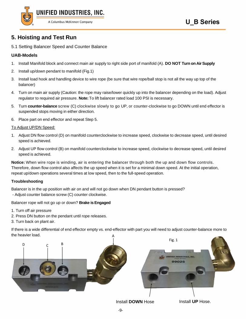
Fig. 1
5. Hoisting and Test Run
5.1 Setting Balancer Speed and Counter Balance
UAB-Models
1. Install Manifold block and connect main air supply to right side port of manifold (A). DO NOT Turn on Air Supply
2. Install up/down pendant to manifold (Fig.1)
3. Install load hook and handling device to wire rope (be sure that wire rope/ball stop is not all the way up top of the balancer)
4. Turn on main air supply (Caution: the rope may raise/lower quickly up into the balancer depending on the load). Adjust
regulator to required air pressure. Note: To lift balancer rated load 100 PSI is necessary.
5. Turn counter-balance screw (C) clockwise slowly to go UP, or counter-clockwise to go DOWN until end effector is suspended stops moving in either direction.
6. Place part on end effector and repeat Step 5.
To Adjust UP/DN Speed:
1. Adjust DN flow control (D) on manifold counterclockwise to increase speed, clockwise to decrease speed, until desired speed is achieved.
2. Adjust UP flow control (B) on manifold counterclockwise to increase speed, clockwise to decrease speed, until desired speed is achieved.
Notice: When wire rope is winding, air is entering the balancer through both the up and down flow controls. Therefore, down flow control also affects the up speed when it is set for a minimal down speed. At the initial operation, repeat up/down operations several times at low speed, then to the full-speed operation.
Troubleshooting
Balancer is in the up position with air on and will not go down when DN pendant button is pressed? - Adjust counter balance screw (C) counter clockwise.
Balancer rope will not go up or down? Brake is Engaged
1. Turn off air pressure 2. Press DN button on the pendant until rope releases. 3. Turn back on plant air.
If there is a wide differential of end effector empty vs. end-effector with part you will need to adjust counter-balance more to the heavier load. A
D C B
Install DOWN Hose Install UP Hose.
-9-
UZB models:
Prior to performing operational adjustments or servicing make sure air supply is off and wire rope is slack.
1. Connect regulator to balancer.
2. Rotate regulator adjustment knob counterclockwise until it stops.
3. Turn on main air supply. Adjust regulator to required air pressure.
4. Rotate adjustment knob clockwise slowly until wire rope begins to raise, move to the full up position. (Ensure the
Brake does not engage - 132 lb. units only).
5. Install load hook and tooling or fixture to wire rope in the required position.
6. Rotate adjustment knob clockwise until load is suspended.
7. The correct setting will require equal effort to lift and lower the load.
8. If unit is required to raise the load out of the way, turn adjustment knob clockwise until desired speed is achieved.
9. Tighten jam nut just above adjustment knob to maintain proper setting.
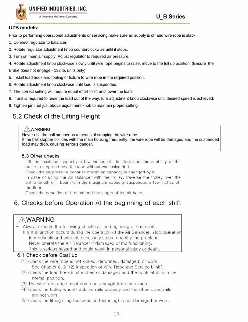
5.2 Check of the Lifting Height
WARNING Never use the ball stopper as a means of stopping the wire rope. If the ball stopper collides with the main housing frequently, the wire rope will be damaged and the suspended load may drop, causing serious danger.
‐10‐
6.2 Check by Idling Operation
(1) Check the indications marked on the push button switches correctly show
the actual directions of up / down operations. (2) Check the ball stopper is not contact with the Main Housing.
(3) Check the Brake System does not work during required work.
6.3 Check by Load Operation (1) Lift the maximum or near the maximum capacity a few inches off the floor
and check ability to stop and hold the load without excessive drift.
(2) Check hoisting speed can be changed from low to high speed by controlling
the pushing force on the push button switches. (3) Check the Air Balancer is not abnormally noisy or vibrating.
7. Periodic Inspections
WARNING - Always put up instruction sign ( " EQUIPMENT BEING INSPECTED",
"DO NOT RUN", etc. ) on the push button switches before carrying
out inspections.
- Periodically, inspect the Air Balancer thoroughly and replace any worn
or damaged parts. - Always shut off the air supply before carrying out inspections.
Exceptions are checks or inspections of the push button switches during that the
Air Balancer should be operated.
Preparing a special table for inspection is recommended.
Monthly Inspection Inspect the Air Balancer at least once a month.
Correct and repair any problems, which are detected.
- Required interval for inspection depends on the operating environment,
operating frequency and loading conditions of the Air Balancer. Therefore, make the inspection interval shorter according to your operating
condition.
- For inspection items and methods, see Chapter 8, Section 8.2 "Inspection".
Service Limit of Parts If any part is found to be worn beyond its service limit in the monthly or other
inspections, never reuse it.
-11-

8. Maintenance and Inspection
Always use the Air Balancer correctly for safety and getting the best service.
8.1 Inspection
(1) Inspection of Hook and Service Limit
Inspection on Hook Opening, Cracks and Wear.
If any of the following conditions apply to the inspected hook, never reuse,
always replace with new one.
- The hook opening is visibly stretched, or the opening dimension is different
from the specified. - The hook is deformed or cracked.
Carefully check for any bends or cracks on the hook shank.
- Wear on the hook saddle, where the lifting sling ( suspension fastening ) rests,
reaches the service limit. - The hook latch is damaged or malfunctioning.
-12-
WARNING Never repair the hooks.
Always replace a stretched, worn or damaged hook with new one.
WARNING
- Never alter the Air Balancer or its accessories. - Always remove the load from the Air Balancer before maintenance, inspection or
repair.
- Always put up an instruction sign ( "EQUIPMENT BEING INSPECTED",
"DO NOT OPEN THE VALUE", etc. ) before carrying out maintenance, inspection
Or repair. - Always shut off the air supply before carrying out maintenance, inspection, or
repair.
Exceptions are checks or inspections of the push button switches during that the
Air Balancer should be operated.
- Always employ specialists or well trained persons for maintenance,
inspection and repair. - Always disassemble the Air Balancer on the floor.
- Always use genuine parts for replacement.
- Replace any parts damaged or worn beyond its service limit.

Hook Opening Dimension and Wear Limit
For hook opening and dimension information please refer to the Warning and Application
Instructions that are supplied to the hook upon purchase of balancer.
(2) Inspection of Wire Rope and Service Limit
Extend the wire rope to the maximum cable travel and then inspect it.
Never use the wire rope having any one of the following defects.
- Kinked, deformed or corroded.
- The number of broken wires reaches the service limit.
- The reduction of diameter reaches the service limit.
Wear Limit and Limit of Broken Wires.
The number of broken wires in on lay should be no greater than 10% of all wires.
In addition, the number of broken wires which are close to each other and in the same strand
should be no greater than 5%.
-13-
(mm) Standard Dimension Service Limit
E 4.76 2.95
Number of
all wires Limit of broken wires
In one lay 10% Close to each other and in the
same strand 5%
133 (7x19) 13 7

Wire rope edge
- Is the Thimble loose?
- Is the Bolt of Clamp loose?
- Is the clamp damaged?
Replacement Parts
Always use a manufacturer's replacement wire rope.
(3) Inspection of Main Housing
- Are there any flaws, cracks, or deformation?
Carefully check the part where the suspension hook is attached.
- Are the bolts loose?
(4) Inspection of Manifold and Control handle
- Are there any flaws, cracks, or deformation or wear on the O-rings?
- Are the springs decayed, cracked or flawed?
- Is the hose damaged, or is the connection part loose?
- Do the push button switch correctly return to the neutral position after being
pushed?
- Are the bolts loose?
8.2 Storing the Air Balancer
If the Air Balancer is to be stored for a long time, store the Air Balancer in dry
location and avoid high or low temperature conditions.
-14-

8.3 Troubleshooting
The following table shows probable cause and solutions of common
malfunctions.
If any malfunctions not shown below happen, please contact your dealer or us.
Malfunction Main Cause Solution
Lifting and
holding
load cannot
be done.
Insufficient air pressure Increase air pressure.
Set air pressure no greater than 0.7Mpa
Load over maximum capacity Check the weight of the load with jig.
Set the load under maximum capacity.
Air leaking from control handle
or hose
Check the hose fitting part. If air leaking
does not stop, replace the control handle or hose
Air leaking between End Cap(M)
and Manifold Replace O-rings of Manifold
Air leaking between End Cap(M)
and Main housing Replace O-rings of End Cap(M)
Irregular
operation Fluctuation of Air pressure Set regulator in air supply line and adjust
air pressure Air containing water, oil, dirt, etc Set filter that can filter to 5 ㎛
-15-
CAUTION Careless repairs can cause damaged to the Air Balancer or personal injury.
Therefore, be careful but through when making repairs.
WARNING If a malfunction occurs during the operation of the Air Balancer,
stop operation immediately and take the necessary steps to rectify the problem.
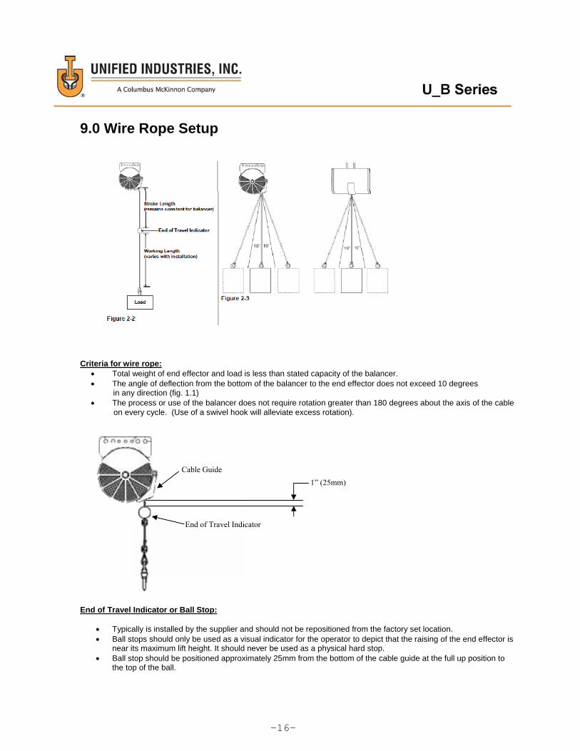
9.0 Wire Rope Setup
Criteria for wire rope: Total weight of end effector and load is less than stated capacity of the balancer. The angle of deflection from the bottom of the balancer to the end effector does not exceed 10 degrees
in any direction (fig. 1.1) The process or use of the balancer does not require rotation greater than 180 degrees about the axis of the cable on every cycle. (Use of a swivel hook will alleviate excess rotation).
End of Travel Indicator or Ball Stop:
Typically is installed by the supplier and should not be repositioned from the factory set location. Ball stops should only be used as a visual indicator for the operator to depict that the raising of the end effector is
near its maximum lift height. It should never be used as a physical hard stop. Ball stop should be positioned approximately 25mm from the bottom of the cable guide at the full up position to
the top of the ball.
-16-
1” (25mm)
Cable Guide
End of Travel Indicator

9.0 Wire Rope Setup (cont.)
Barrel Nut Location:
A single barrel nut is required to position the ball stop. A single barrel nut is required to properly secure the cable above the thimble (87 in-lbs). Barrel nut is used to secure end of the cable after it has been properly located around the required thimble
and through the load hook. Approximately 25mm (1 inch) of the cable end should extend out past the top of the barrel nut (see figure
below) The Barrel nut should be positioned approximately 150mm (6 inches) from the bottom of the ball stop
(end of travel indicator) to the top of the barrel nut. Barrel nut hardware to be torqued to (87 in-lbs). Never use multiple barrel nuts to secure the ball stop or the load thimble. NOTE: Additional cable/barrel clamps are not needed to supplement the OEM rigging. Adding additional cable clamps may weaken the wire rope.
Hook Connection:
Approximately 25mm (1 inch) of cable should extend past the top of the barrel nut. Once barrel nut is secured to recommended torque (87 in-lbs)
-17-
6” (150mm)
Cable Guide
Barrel Nut
End of Travel Indicator
1” (25mm)
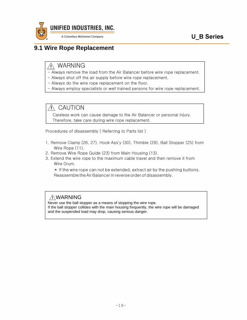
9.1 Wire Rope Replacement
Procedures of disassembly ( Referring to Parts list )
1. Remove Clamp (26, 27), Hook Ass'y (30), Thimble (29), Ball Stopper (25) from
Wire Rope (11). 2. Remove Wire Rope Guide (23) from Main Housing (13). 3. Extend the wire rope to the maximum cable travel and then remove it from
Wire Drum.
* If the wire rope can not be extended, extract air by the pushing buttons.
Reassemble the Air Balancer in reverse order of disassembly.
WARNING Never use the ball stopper as a means of stopping the wire rope. If the ball stopper collides with the main housing frequently, the wire rope will be damaged and the suspended load may drop, causing serious danger.
-18-
CAUTION Careless work can cause damage to the Air Balancer or personal injury.
Therefore, take care during wire rope replacement.
WARNING - Always remove the load from the Air Balancer before wire rope replacement.
- Always shut off the air supply before wire rope replacement.
- Always do the wire rope replacement on the floor.
- Always employ specialists or well trained persons for wire rope replacement.
11. Parts list 11.1 KAB-070 Unit (KAB-070-1000)
No. Part No. Description Qty No. Part No. Description Qty
1 070-1004 End Cap (B) 1 21 070-1006 Lock Nut 1
2 070-7001 Rachet Wheel 5 22 070-1007 Washer 1
3 070-7003 Brake Pawl 1 23 070-1023 Wire Rope Guide 1
4 070-7002 Brake Rotor 1 24 070-1024 Guide Plate_(L) 1
5 070-7004 Pin 1 25 070-1026 Ball Stopper 1
6 070-7012 Snap Ring 1 26 070-1028 Clamp_A 2
7 070-7005 Bearing Retainer 1 27 070-1029 Clamp_B 2
8 000-4000 Ball Screw Ass'y 1 28 070-1035 Hex Bolt 4
9 070-1012 Bearing Retainer 1 29 070-1015 Wire Protection Guide 1
10 070-1010 Drum 1 30 070-1027 Hook Ass'y 1
11 070-1022 Wire Rope 1 31 070-1009 Pin 1
12 070-1011 Thrust Bearing 1 32 070-7007 Brake Shaft 1
13 070-1013 Main Housing Ass'y 1 33 070-7008 Bearing 1
14 070-1014 Piston Ass'y 1 34 070-7009 Flush Machine Screw 1
15 070-1017 O-Ring 1 35 070-7006 Spring 1
16 070-1019 End cap (M) 1 36 070-7010 Hex. Head Bolt 4
17 070-1021 Hex. Bolt 1 37 070-1005 Hex. Head Bolt 2
18 070-1018 O-Ring 1 38 070-1003 Spring Pin 2
19 070-1016 Ball Screw Cap 1 39 070-1002 Washer 2
20 070-1025 Guide Plate_(H) 1 40 070-1001 Hex. Bolt 1
-19-

No. Part No. Description Qty No. Part No. Description Qty
1 100-1004 End Cap (B) 1 24 100-1016 Ball Screw Cap 1
2 100-1005 Hex. Bolt 4 25 100-1025 Hex Bolt 1
3 100-7001 Ratchet Wheel 5 26 100-1006 Washer 1
4 100-7010 Hex. Bolt 4 27 100-1024 Guide Plate 1
5 100-7002 Brake Rotor 1 28 100-1023 Wire Rope Guide 1
6 100-7003 Brake Pawl 1 29 100-1037 Flush Machine Screw 1
7 100-7005 Bearing Retainer 1 30 100-1038 Lock Nut 1
8 100-7007 Brake Shaft 2 31 100-1026 Ball Stopper 1
9 100-4000 Ball Screw Ass'y 1 32 100-1028 Clamp_A 2
10 100-1010 Wire Drum 1 33 100-1035 Hex Bolt 4
11 100-1022 Wire Rope 1 34 100-1029 Clamp_B 2
12 - - 1 35 100-1015 Wire Protection Guide 2
13 100-1013 Main Housing Ass'y 1 36 100-1027 Hook Ass'y 1
14 100-1031 Bracket Ass'y 1 37 100-1009 Ball Screw Fixed Pin 1
15 100-1035 Hex Bolt 2 38 100-7008 Ball Bearing 1
16 100-1036 Lock Nut 2 39 100-7012 Snap Ring 1
17 100-1012 Bearing Retainer 1 40 100-7004 Brake Pin 1
18 100-1011 Thrust Bearing 1 41 100-7006 Spring 1
19 100-1014 Piston Ass'y 1 42 100-7009 Flush machine Screw 2
20 100-1018 O-ring 1 43 100-1003 Spring Pin 2
21 100-1019 End Cap (M) 1 44 100-1002 Washer 2
22 100-1021 Hex Bolt 1 45 100-1001 Hex. Bolt 1
23 100-1017 O-ring
-20-

No. Part No. Description Qty No. Part No. Description Qty
1 160-1004 End Cap (B) 1 24 160-1016 Ball Screw Cap 1
2 160-1005 Hex. Bolt 4 25 160-1025 Hex Bolt 1
3 160-7001 Ratchet Wheel 5 26 160-1006 Washer 1
4 160-7010 Hex. Bolt 4 27 160-1024 Guide Plate 1
5 160-7002 Brake Rotor 1 28 160-1023 Wire Rope Guide 1
6 160-7003 Brake Pawl 1 29 160-1037 Hex Bolt 1
7 160-7005 Bearing Retainer 1 30 160-1038 Lock Nut 1
8 160-7007 Brake Shaft 2 31 160-1026 Ball Stopper 1
9 000-4000 Ball Screw Ass'y 1 32 160-1028 Clamp_A 1
10 160-1010 Wire Drum 1 33 160-1035 Hex Bolt 2
11 160-1022 Wire Rope 1 34 160-1029 Clamp_B 4
12 - - - 35 160-1015 Wire Protection Guide 2
13 160-1013 Main Housing Ass'y 1 36 160-1027 Hook Ass'y 1
14 160-1031 Bracket Ass'y 1 37 160-1009 Ball Screw Fixed Pin 1
15 160-1035 Hex Bolt 2 38 160-7008 Bal bearing 1
16 160-1036 Lock Nut 2 39 160-7012 Snap Ring 1
17 160-1012 Bearing Retainer 1 40 160-7004 Brake Pin 1
18 160-1011 Thrust Bearing 1 41 160-7006 Spring 1
19 160-1014 Piston Ass'y 1 42 160-7009 Flush Machine Screw 2
20 160-1018 O-ring 1 43 160-1003 Spring Pin 2
21 160-1019 End Cap (M) 1 44 160-1002 Washer 2
22 160-1021 Hex Bolt 1 45 160-1001 Hex. Bolt 1
23 160-1017 O-ring
-21-

No. Part No. Description Qty No. Part No. Description Qty
1 230-1004 End Cap (B) 1 24 230-1016 Ball Screw Cap 1
2 230-1005 Hex. Bolt 4 25 230-1025 Hex Bolt 1
3 230-7001 Ratchet Wheel 5 26 230-1006 Washer 1
4 230-7010 Hex. Bolt 4 27 230-1024 Guide Plate 1
5 230-7002 Brake Rotor 1 28 230-1023 Wire Rope Guide 1
6 230-7003 Brake Pawl 1 29 230-1037 Hex Bolt 1
7 230-7005 Bearing Retainer 1 30 230-1038 Lock Nut 1
8 230-7007 Brake Shaft 2 31 230-1026 Ball Stopper 1
9 000-4000 Ball Screw Ass'y 1 32 230-1028 Clamp_A 1
10 230-1010 Wire Drum 1 33 230-1035 Hex Bolt 2
11 230-1022 Wire Rope 1 34 230-1029 Clamp_B 4
12 - - - 35 230-1015 Wire Protection Guide 2
13 230-1013 Main Housing Ass'y 1 36 230-1027 Hook Ass'y 1
14 230-1031 Bracket Ass'y 1 37 230-1009 Ball Screw Fixed Pin 1
15 230-1035 Hex Bolt 2 38 230-7008 Bal bearing 1
16 230-1036 Lock Nut 2 39 230-7012 Snap Ring 1
17 230-1012 Bearing Retainer 1 40 230-7004 Brake Pin 1
18 230-1011 Thrust Bearing 1 41 230-7006 Spring 1
19 230-1014 Piston Ass'y 1 42 230-7009 Flush Machine Screw 2
20 230-1018 O-ring 1 43 230-1003 Spring Pin 2
21 230-1019 End Cap (M) 1 44 230-1002 Washer 2
22 230-1021 Hex Bolt 1 45 230-1001 Hex. Bolt 1
23 230-1017 O-ring
-22-
2
4
1
10.5 UAB Manifold Unit (99025)
6
5
3
No. Part No. Description Qty.
1 51677 Hex Head Bolt 4
2 52496 Spring Washer 4
3 99025 Manifold Body 1
4 000-2005 O-Ring 1
5 99030 Street Elbow 1
6 99048 1/2” Check Valve 1
-23-

2 000-6002 Hex. Bolt 1 4 000-6004 Hex. Nut 1
-24-

10.7 Reeved Hook Unit
No. Part No. Description Qty No. Part No. Description Qty
1 200-1001 Wheel 1 9 200-1009 Reeved Plate 1
2 200-1002 Shaft Pin 1 10 200-1011 Bearing 2
3 200-1003 Bottom Plate 1 11 200-1012 Bearing 1
4 200-1004 Upper Plate 1 12 200-1013 Snap ring 2
5 200-1005 Side Plate 2 13 200-1014 Bolt 4
6 200-1006 Guide Plate 2 14 200-1015 Nut 4
7 200-1007 Hook Ass'y 1 15 200-1016 Spring pin 2
8 200-1008 Spacer 2 16 200-1017 Bolt 2
-25-

10.8 INSPECTION AND MAINTENANCE PROCEDURE
Inspection Procedures Frequency
Check the wire rope to make sure that is not kinked, deformed, damaged, or worn. (Also see balancer manual “Wear Limit and Limit of Broken Wires”)
Daily or prior to each use
Check the load hook to see if it is stretched or damaged and verify the hook latch is in the normal position.
Daily or prior to each use
Check the trolley wheel track and verify the rails as well as the trolleys wheels are not worn.
6 months
Check balancer for loose mounts, bolts, nuts and hardware. Ensure proper attachments to trolleys. Balancer suspension kit hardware is to be snug tight only. Do not overtighten. Bolts that connect mounting bracket assembly to main housing assembly are to be torqued to 32 ft-lbs. Barrel nut hardware are to be torqued to 87 in-lbs.
3 months
Check the indications marked on the push button switches correctly show the actual directions of up/down operations.
Daily or prior to each use
Check the ball stopper is not in contact with the man housing when in the fully up position.
Daily or prior to each use
Lift the maximum or near the maximum capacity a few inches off the floor and check ability to stop and hold the load without excessive drift.
Daily or prior to each use
Run balancer up and down with no load one cycle. Check balancer is not abnormally noisy or vibrating.
Daily or prior to each use
Verify wire rope end is 1” above the clamp 1 Month
-26-

Main Office & Factory
1033 Sutton Street
Howell, MI 48843
TEL : ( 51 7) 546-3220 FAX : ( 51 7) 54 6- 0696
WEB SITE : http://www.unified-ind.com