MODEL # 101487 Operation Manual - Dirty Hand...
28
21” SNOW THROWER is safety alert symbol identifies important safety messages in this manual. Failure to follow this important safety information may result in serious injury or death. MODEL # 101487 Operation Manual ! Part # 101475 Rev C
Transcript of MODEL # 101487 Operation Manual - Dirty Hand...

21” SNOW THROWER
�is safety alert symbol identi�es important safety messages in this manual. Failure to follow this important safety information may result in serious injury or death.
MODEL # 101487
Operation Manual
!Part # 101475 Rev C

1100 W 120th Ave, Suite 600Westminster, CO 80234 • 720-287-5182
For Service or QuestionsCall 1-877-487-8275720-287-5182
www.dirtyhandtools.comDirty Hand Tools® is a brand of

Table of Contents
Important Safety Information .....................................................4Overview ........................................................................................7Assembly ........................................................................................8Filling with Gasoline and Oil .......................................................10Operation Precautions ..................................................................11Operation Controls ......................................................................13Operation .....................................................................................14Maintenance .................................................................................16Troubleshooting ...........................................................................24Storage .........................................................................................27Warranty and Specifications ..........................................Back Cover
3
Important Safety Information
WARNING: Read and thoroughly understand all instructions and safety information before operating this Snow thrower. Failure to do so may cause serious injury or death. Do not allow anyone to operate this Snow thrower who has not read this manual. As with all power equipment, a snow thrower can be dangerous if used improperly. Do not operate this snow thrower if you have doubts or questions concerning safe operation.
Call our customer service department at 720-287-5182, 1-877-487-8275, or visit www.dirtyhandtools.com if you have any questions or concerns about the safe operation of this equipment.
Intended UseDo Not Use the Snow thrower for any purpose other than for which it was designed. Any other use is unauthorized and may result in serious injury or death.
Personal Protective EquipmentWear ANSI-approved safety goggles, heavy-duty work boots and gloves during set up and operation. While this snow thrower operates at a relatively low noise level, about 74dB, you may want to wear ear plugs or noise deafening headphones.
A SNOW THROWER IS CAPABLE OF AMPUTATING HANDS AND FEET AND THROWING OBJECTS.
FAILURE TO OBSERVE THE SAFETY INSTRUCTIONS COULD RESULT IN SERIOUS INJURY OR DEATH.
4
!WARNING
!DANGER
!DANGER
5
Important Safety Information
General SafetyFailure to follow warnings, cautions, assembly and operation instructions in the Operation Manual may result in serious injury or death.
READ THE OPERATION MANUAL BEFORE OPERATION.
• Do not permit children to operate this equipment at any time. Do not permit others that have not read and understood the complete Operation Manual to operate this equipment.
• Do not operate the snow thrower when under the influence of alcohol, drugs or medication.
• Do not allow a person who is tired, or otherwise impaired, or not completely alert to operate the snow thrower.
NEVER place �ngers, hands, or body near the snow thrower when it is running. Do not lean or reach over the snow thrower.
Do not aim the discharge at a person or animal.
• Keep all safety guards in place and in proper working order.• Keep all people (except the operator) a minimum of 25 feet from
the snow thrower during operation.• Do not transport the snow thrower with the engine running.• Do not tilt the machine while the engine is running.• Do not leave the snow thrower unattended when it is running.
Turn off the engine before leaving the area.• Never run the engine in an enclosed area or without proper
ventilation as the exhaust from the engine contains carbon monoxide, which is an odorless, tasteless, and deadly poisonous.
• Fill the gasoline tank outdoors with the engine off and allow the engine to cool completely.
• Do not operate the engine with the air cleaner or cover over the carburetor air-intake removed, except for adjustment. Removal of such parts could create a fire hazard.
• �e mu�er and engine become very hot with use and can cause a severe burn; do not touch. Allow the engine to cool before refueling, doing maintenance, or making adjustments.
!DANGER
!DANGER

6
Important Safety Information
Safety Decals
Safety labels on the snow thrower are to remind you of important information while you are operating the unit. Make sure all safety warning decals are attached and in readable condition. Replace missing or defaced decals. Contact Dirty Hand Tools at 1-877-487-8275 for replacement decals.
DANGER
AVOID INJURY FROMROTATING AUGER!KEEP HANDS, FEET
AND CLOTHING AWAY!
DANGER1. KEEP AWAY FROM ROTATING IMPELLER AND AUGER. CONTACT WITH IMPELLER OR AUGER CAN AMPUTATE HANDS AND FEET.2. USE CLEAN-OUT TOOL TO UNCLOG DISCHARGE CHUTE. DO NOT USE HANDS!3. DISENGAGE CLUTCH LEVERS, STOP ENGINE, AND REMAIN BEHIND HANDLES UNTIL ALL MOVING PARTS HAVE STOPPED BEFORE UNCLOGGING OR SERVICING MACHINE.4. TO AVOID THROWN OBJECT INJURY, NEVER DIRECT DISCHARGE AT BYSTANDERS OR ANIMALS. USE EXTRA CARE WHEN OPERATING ON GRAVEL SURFACES.5. READ OPERATION MANUAL BEFORE USING.
CLEAN-OUT TOOL
DANGER
STOP THE ENGINEBEFORE UNCLOGGING
DISCHARGE CHUTE!
To prevent serious injury and fire:1. Do not add fuel while the engine is running or when the engine is hot.2. Do not smoke while filling with fuel.3. Do not overfill.Use only fresh gasoline. Empty fuel before storage. 101068

7
Overview
Your snow thrower requires some assembly. Save the packing materials and box for future use as a storage container. COMPLETELY READ AND UNDERSTAND THE OPERATOR’S MANUAL BEFORE ATTEMPTING TO OPERATE THE SNOW THROWER.
DRIVECONTROL
AUGERCONTROL
CHUTE TILTCONTROL
CHUTEDIRECTIONCONTROL
ADJUSTABLESKIDSHOE
SPEEDCONTROL
AUGER
MUFFLER
AIR FILTERCOVER

8
Assembly
Handlebar and Control Assembly
1. Hex bolts and nylon lock nuts have been provided in a hardware package. Align the two holes at each end of the handlebar with the two holes in the handlebar support on the snow thrower. Push hex bolts through from the outside and secure with a nylon lock nut on the interior in two places on both sides of the snow thrower. Tighten securely (see Figure 1).
2. Attach the drive wire on the le� side of the snow thrower (see Figure 2). Remove the R-clip that connects the drive wire to the control lever on the handlebars, then slip the wire o�. Attach the other end of the drive wire with the spring mechanism to the connection ring and reattach the drive wire to the control lever reinserting the R-clip. A�er connecting the wire adjust the tension. �e wire should be taught when connected. (See Control Wire Adjustment, page 23).
3. Attach the auger wire on the right side of the snow thrower (see Figure 3). Remove the R-clip that connects the auger wire to the control lever on the handlebars, then slip the wire o�. Attach the other end of the auger wire with the spring mechanism to the connection and reattach the auger wire to the control lever reinserting the R-clip. A�er connecting the wire adjust the tension. �e wire should be taught when connected. (See Control Wire Adjustment, page 23).
4. Attach the speed shi� rod and secure with a R-clip that has been included in the hardware package (see Figure 3).
HEX BOLT & NYLON LOCK NUT(4 PLACES)
DRIVE WIRE
Figure 2
Figure 1
AUGER WIRE
Figure 3
SPEED SHIFT ROD
CONNECTION RING
R-CLIP

9
Assembly
Attaching the Discharge Chute1. Attach the discharge chute and handle to the snow thrower by
placing it on the chute seat on the snow thrower, aligning the holes in three places and pushing a bolt from the inside out, through the chute and chute handle and securing with a nylon lock nut on the exterior (see Figure 4). �e distance snow is thrown can be adjusted by changing the angle of the chute tilt by loosening the wing knob found on the left side of the chute assembly. Pivot the chute upward or downward then retighten the wing knob.
SKID SHOE
HEX NUT(2 PLACES)
Adjusting the Skid Shoes1. Position the skid shoes based on surface conditions. Adjust
upward for hard-packed snow. Adjust downward when operating on gravel or crushed rock surfaces. Loosen the two hex nuts that retain the skid shoe in place and move up or down as desired, then retighten the lock nuts (see Figure 5). Repeat for the opposite side of the snow thrower.
Figure 5
CHUTE SEAT
DISCHARGECHUTE
NYLON LOCK NUT& BOLT
(3 PLACES)
Figure 4
CHUTETILT
HANDLE

10
Filling with Gasoline and Oil
FUEL IS HIGHLY FLAMMABLE AND POISONOUSALWAYS FILL THE TANK WITH
ENGINE OFF AND COOL. ALWAYS CHECK THE FUEL LEVEL
BEFORE OPERATING.
Allow the engine to cool for at least two minutes before removing the fuel cap.
1. Place the snow thrower on a level surface outdoors to fuel.2. �e fuel tank holds approximately 0.8 gallons of fuel. 87+
octane unleaded gasoline is recommended. Do not fill above the top of the fuel filter. Replace the fuel cap securely and wipe any excess from the fuel tank before starting the snow thrower.
DO NOT REFUEL INDOORS OR NEAR ANY SOURCE OF POSSIBLE COMBUSTION.
DO NOT SMOKE WHILE FUELING.DO NOT OVERFILL.
THE SNOW THROWER IS SHIPPED WITHOUT FLUIDS. YOU MUST ADD OIL BEFORE STARTING
THE ENGINE.
3. Add engine oil to the upper level of the oil filler hole. SAE 10/30 motor oil is recommended for most environmental conditions. �e oil capacity is 0.63 quarts (0.6L).
Note: Do not thread the dipstick in when checking the oil level.
!WARNING
!WARNING
WARNINGGASOLINE
FUEL ONLY!DO NOT USEDIESEL FUEL
101120
101071
101127
To prevent serious injury and fire:1. Do not add fuel while the engine is hot or running.2. Do not smoke while filling with fuel.3. Do not overfill. Empty fuel before storage.
11
Operation Precautions
COMPLETELY READ AND UNDERSTAND THIS MANUAL BEFORE ATTEMPTING TO OPERATE
THE SNOW THROWER
1. Keep all safety guards in place and in proper working order at all times.
2. NEVER place fingers, hands, or body near the snow thrower when it is running. Do not lean or reach over the snow thrower when the machine is running.
STOP THE ENGINE TO UNCLOG THE DISCHARGE CHUTE. NEVER USE YOUR HAND TO CLEAN OUT
THE DISCHARGE CHUTE OR AUGERS.
3. Always stop the engine to dislodge snow from the discharge chute or from the augers. Wait ten seconds for the augers to stop rotating. Never use your hands to clear out the augers or discharge chute. Always use the clear-out tool provided or a similar tool.
4. Keep all people (except the operator) a minimum of 25 feet from the snow thrower during operation.
5. Always aim the discharge chute away from people and animals.6. Do not leave the snow thrower unattended when it is running.
Turn off the engine before leaving the area.7. Do not use this piece of equipment while tired or under the
influence of drugs, alcohol or medication.8. Parts, especially exhaust system components, get very hot
during use. Stay clear of hot parts.9. Use extra caution when operating on gravel or other loose
material.
!DANGER
!DANGER
12
Operation Precautions
DISENGAGE ALL CONTROL LEVERS AND STOP THE ENGINE BEFORE YOU LEAVE THE
OPERATING POSITION. Wait until the auger/impeller comes to a complete stop
before unclogging the chute assembly, making any adjustments, or inspections.
1. Exercise caution to avoid slipping or falling, especially when operating in reverse.
2. �oroughly inspect the area where the equipment is to be used. Remove all foreign objects, which could be tripped over or thrown by the auger/impeller.
3. Always wear safety glasses or eye shields during operation and while performing an adjustment or repair to protect your eyes. �rown objects which ricochet can cause serious injury to the eyes.
4. Operate the equipment with appropriate footware, gloves and clothing. Avoid loose fitting clothing that can get caught in moving parts.
5. After striking a foreign object, stop the engine, remove the wire from the spark plug, thoroughly inspect the snow thrower for any damage, and repair the damage before restarting and operating the snow thrower.
6. �e auger and drive controls must be depressed to operate. Do not override this safety feature. Both control levers must operate easily and automatically return to the disengaged position when released.
7. Do not overload the snow thrower by attempting to clear snow too quickly.
8. Do not operate at high speed on icy or slippery surfaces.9. Always be sure of your footing especially when driving in
reverse.10. If the snow thrower should vibrate abnormally, stop the
engine immediately, disconnect the spark plug and inspect for damage
!CAUTION
13
Operation Control
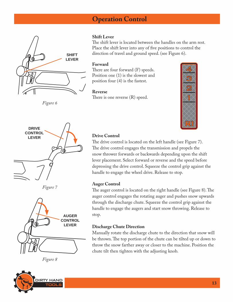
Shift Lever�e shift lever is located between the handles on the arm rest. Place the shift lever into any of five positions to control the direction of travel and ground speed. (see Figure 6).
Forward�ere are four forward (F) speeds. Position one (1) is the slowest and position four (4) is the fastest.
Reverse�ere is one reverse (R) speed.
Drive Control�e drive control is located on the left handle (see Figure 7). �e drive control engages the transmission and propels the snow thrower forwards or backwards depending upon the shift lever placement. Select forward or reverse and the speed before depressing the drive control. Squeeze the control grip against the handle to engage the wheel drive. Release to stop.
Auger Control�e auger control is located on the right handle (see Figure 8). �e auger control engages the rotating auger and pushes snow upwards through the discharge chute. Squeeze the control grip against the handle to engage the augers and start snow throwing. Release to stop.
Discharge Chute DirectionManually rotate the discharge chute to the direction that snow will be thrown. �e top portion of the chute can be tilted up or down to throw the snow farther away or closer to the machine. Position the chute tilt then tighten with the adjusting knob.
SHIFTLEVER
AUGERCONTROL
LEVER
DRIVECONTROL
LEVER
Figure 6
Figure 7
Figure 8
14
Operation
FILL WITH OIL BEFORE STARTINGMake sure the auger control and drive control are in the
disengaged (released) position.
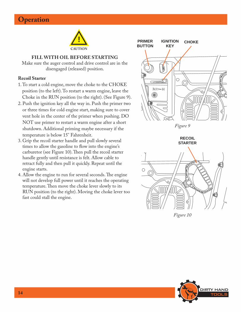
Recoil Starter1. To start a cold engine, move the choke to the CHOKE
position (to the left). To restart a warm engine, leave the Choke in the RUN position (to the right). (See Figure 9).
2. Push the ignition key all the way in. Push the primer two or three times for cold engine start, making sure to cover vent hole in the center of the primer when pushing. DO NOT use primer to restart a warm engine after a short shutdown. Additional priming maybe necessary if the temperature is below 15° Fahrenheit.
3. Grip the recoil starter handle and pull slowly several times to allow the gasoline to flow into the engine’s carburetor (see Figure 10). �en pull the recoil starter handle gently until resistance is felt. Allow cable to retract fully and then pull it quickly. Repeat until the engine starts.
4. Allow the engine to run for several seconds. �e engine will not develop full power until it reaches the operating temperature. �en move the choke lever slowly to its RUN position (to the right). Moving the choke lever too fast could stall the engine.
!CAUTION
Figure 9
CHOKEPRIMERBUTTON
IGNITION KEY
RECOILSTARTER
Figure 10

15
OperationEngaging the Drive and Auger Controls1. With the throttle control in the fast position, move shift lever
into one of the four forward (F) or one reverse (R) positions. Select a speed appropriate for the snow conditions and a pace you’re comfortable with. When selecting a drive speed, use slower speeds until you are familiar with the operation of the snow thrower.
2. Squeeze the auger control against the handle and the auger will turn. Release it and the augers will stop.
3. Squeeze the drive control against the handle and snow thrower will move. Release it and drive motion will stop.
Do not reposition the shift lever (change speeds or direction of travel)
without �rst releasing the drive controland bringing the snow thrower to a complete stop.
Shifting between speeds or directions while the drive control is is engaged will result in premature wear
to the snow thrower’s drive system.
4. Release both the auger control and the drive control to redirect the discharge chute.
5. To move from forward to reverse, release the drive control and the auger control and allow the rotating augers to stop before moving the shift lever to a new position.
6. ALWAYS release the auger and drive control and turn the engine off before dislodging snow accumulation from the augers or unclogging the discharge chute. ALWAYS use the clean-out tool provided. NEVER use your hands at any time to dislodge snow form the augers or unclog the discharge chute.
!CAUTION

16
Maintenance
BEFORE PERFORMING ANY MAINTENANCE PROCEDURE STOP THE ENGINE, WAIT FIVE (5)
MINUTES TO ALLOW ALL PARTS TO COOL.Disconnect the spark plug wire,
keeping it away from the spark plug.
Regular maintenance is the way to ensure the best performance and long life of your machine. Please refer to this manual and theengine manufacturer’s owner’s manual for maintenance procedures.
!WARNING
Maintenance Before Monthly/ Every 6 Mo./ Annually/ Procedure Each Use 20 Hours 100 Hours 300 Hours
Check Engine Oil & Fuel Levels X X X X
Check General Equipment Condition X
Lubricate Gear Shaft & Auger Shaft X X X
Lubricate Wheels & Discharge Chute X
Check Air Cleaner X X X
Check Fuel Strainer X X X
Clean/Replace Air Filter X X X
Check/Clean Spark Plug* X X
Check/Adjust Idle Speed X X
Check/Adjust Valve Clearance X X
Clean Fuel Tank, Strainer & Carburetor X X
Change Oil X
Clean Combustion Chamber** X
Replace Fuel Lines** X
Maintenance Checklist
* Replace spark plug if white insulator is cracked or chipped** Service performed by qualified technician

17
Maintenance
TO PREVENT SERIOUS INJURY FROM ACCIDENTAL STARTING TURN THE POWER
SWITCH OF THE ENGINE TO ITS “OFF” POSITION.
Wait for the engine to cool, and remove the spark plug wire before performing any inspection, maintenance, or cleaning
procedures.
Changing /Cleaning the Air Filter1. Wipe off the air cleaner cover. Loosen the knob at the bottom
of the air cleaner housing (see Figure 11).2. Remove the air cleaner filter.3. Wash the air filter in warm water and mild detergent several
times. Rinse. Squeeze out excess water and allow it to dry completely. Soak the filter in lightweight oil briefly, then squeeze out the excess oil.
4. Install a new air filter or reinstall the cleaned air filter. Secure the air cleaner cover before use.
Spark Plug Maintenance:1. Disconnect spark plug wire from end of plug. Clean out debris
from around the spark plug.2. Using the spark plug wrench provided, remove the spark plug.
Inspect the spark plug. If the electrode is oily, clean it using a clean, dry rag. If the electrode has deposits on it, polish it using emery paper. If the white insulator is cracked or chipped, replace the spark plug.
3. When installing a new spark plug, adjust the plug’s gap to the speci�cation on the technical speci�cation chart. Do not pry against the electrode or the insulator, the spark plug can be damaged (see Figure 12).
4. Install the new spark plug or the cleaned spark plug into the engine. Gasket style spark plugs should be �nger-tightened until the gasket contacts the cylinder head, then turned about 1/2 to 2/3 more rotation. Non-gasket-style spark plugs should be �nger-tightened until the plug contacts the head, then about 1/16 turn more.
!WARNING
Figure 11
AIRCLEANER
COVER
Figure 12
Spark Plug Gap0.028”~ 0.031”

18
Maintenance
OIL IS VERY HOT DURING OPERATION AND CANCAUSE BURNS. WAIT FOR ENGINE TO COOL
BEFORE CHANGING OIL.
Wait for the engine to cool, and remove the spark plug wire before performing any inspection, maintenance, or cleaning
procedures.
Changing the engine oil1. Make sure the engine is stopped and is level.2. Close the fuel valve.3. Place a drain pan underneath the crankcase’s drain plug.4. Remove the drain plug and, if possible, tilt the crankcase
slightly to help drain the oil out. 5. Replace the drain plug and tighten it.6. Clean the top of the dipstick and the area around it. Remove
the dipstick by threading it counterclockwise, and wipe it off with a clean lint free rag.
Note: Do not thread the dipstick in when checking the oil level.
7. Add the appropriate type of oil until the oil level is at the full level. SAE 10W-30 oil is recommended for general use for temperatures above 32°F. Use SAE 5W-30 for temperatures consistently below 32°F.
8. �read the dipstick back in clockwise.
DO NOT RUN THE ENGINE WITH TOO LITTLEOIL. THE ENGINE WILL BE PERMANENTLY
DAMAGED.
!WARNING
!WARNING
SAE VISCOSITY GRADES
AVERAGE OUTSIDE TEMPERATURE
30W
10W - 30W
5W - 30W
-20 0 20 40 60 80 100°F

19
Maintenance
LUBRICATION
Gear Shaft�e gear (hex) shaft should be lubricated at least once a season or after every 20 hours of operation.1. Remove the lower frame cover by removing the two screws
which secure it (see Figure 13).2. Apply a light coating of an all-weather multi-purpose grease to
the hex shaft (see Figure 14).
WheelsAt least once a season, remove both wheels. Clean and coat the axles with a multipurpose automotive grease then reinstall.
Auger ShaftAt least once a season, remove the shear pins on the auger shaft (see Figure 15). Spray lubricant inside shaft, around the spacers. Also lubricate the flange bearings found at either end of the shaft.
Gear Case�e auger gear case has been filled with grease and sealed at the factory. If disassembled from any reason, lubricate with two ounces of new grease.
NOTE: Do not over fill the gear case. Damage to the seals could result. Be sure the vent plug is free of grease in order to relieve pressure.
Figure 14
GEAR (HEX) SHAFT
Figure 15
SHEARPIN
SPACERS
BEARING
FRAMECOVER
Figure 13
COTTERPIN

20
MaintenanceShear Pin Replacement�e auger is attached to the spiral shaft with shear pins secured with cotter pins. If the auger should strike a foreign object or ice jam, the snow thrower is designed to shear off those pins (see Figure 16). If the auger will not rotate, check if the pins have been sheared. When replacing shear pins, spray an oil lubricant into the shaft before inserting new pins.
Shave Plate and Skid Shoes�e shave plate and skid shoes on the bottom of the snow thrower are subject to wear. �ey should be checked periodically and replaced when necessary.
To remove skid shoes:1. Remove the four carriage bolts and hex flange nuts which
secure them to the snow thrower (see Figure 17).2. Reassemble new skid shoes with the four carriage bolts
(two on each side) and hex flange nuts.
To remove shave plate:1. Remove the carriage bolts and hex nuts which attach it to
the snow thrower housing (see Figure 17).2. Reassemble new shave plate, making sure heads of carriage
bolts are to the inside of housing. Tighten securely.
Figure 17
SKIDSHOE
SHAVEPLATE
Figure 16
SHEARPIN
COTTERPIN
21
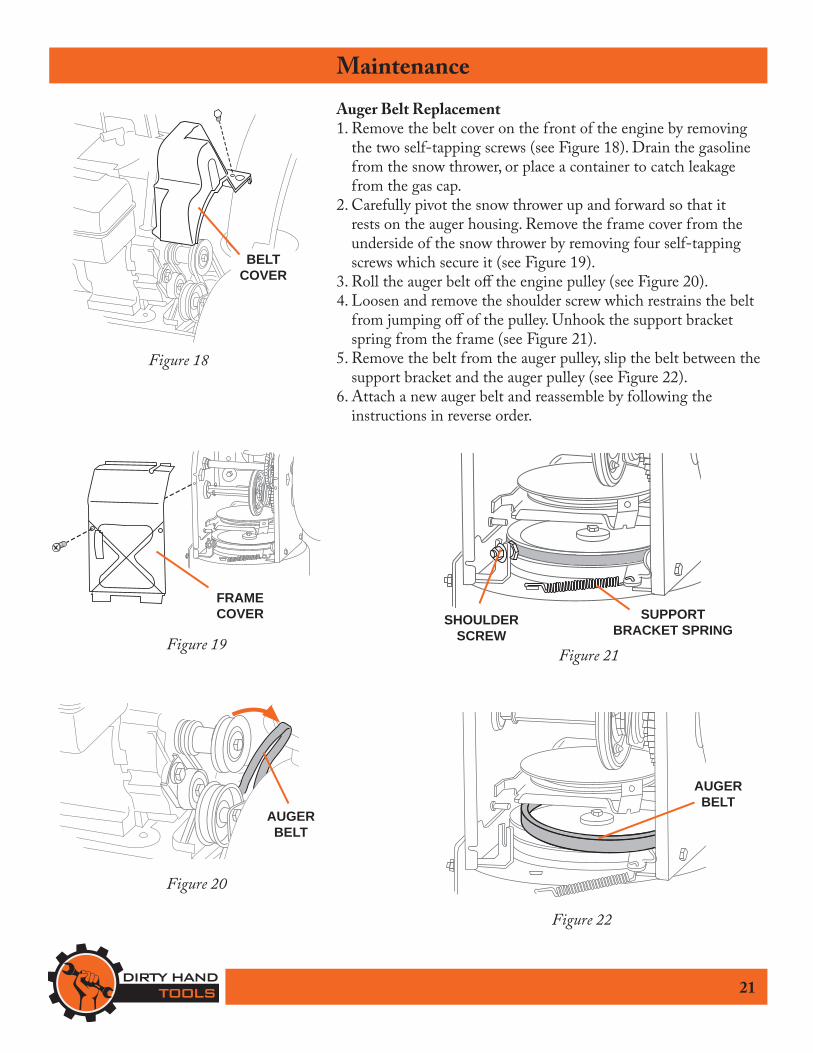
MaintenanceAuger Belt Replacement1. Remove the belt cover on the front of the engine by removing
the two self-tapping screws (see Figure 18). Drain the gasoline from the snow thrower, or place a container to catch leakage from the gas cap.
2. Carefully pivot the snow thrower up and forward so that it rests on the auger housing. Remove the frame cover from the underside of the snow thrower by removing four self-tapping screws which secure it (see Figure 19).
3. Roll the auger belt off the engine pulley (see Figure 20).4. Loosen and remove the shoulder screw which restrains the belt
from jumping off of the pulley. Unhook the support bracket spring from the frame (see Figure 21).
5. Remove the belt from the auger pulley, slip the belt between the support bracket and the auger pulley (see Figure 22).
6. Attach a new auger belt and reassemble by following the instructions in reverse order.
FRAMECOVER
BELT COVER
Figure 18
Figure 19SHOULDER
SCREWSUPPORT
BRACKET SPRING
Figure 21
AUGERBELT
Figure 22
AUGERBELT
Figure 20

22
MaintenanceDrive Belt Replacement1. Remove the belt cover on the front of the engine by
removing the two self-tapping screws (see Figure 18). Drain the gasoline from the snow thrower, or place a container to catch leakage from the gas cap.
2. Carefully pivot the snow thrower up and forward so that it rests on the auger housing. Remove the frame cover from the underside of the snow thrower by removing four self-tapping screws which secure it (see Figure 19).
3. Roll the auger belt off the engine pulley (see Figure 20).4. Loosen and remove the shoulder screw which restrains the
belt from jumping off of the pulley. Unhook the support bracket spring from the frame (see Figure 21).
5. Remove the belt from the auger pulley, slip the belt between the support bracket and the auger pulley (see Figure 22).
6. See Figure 23 and follow the steps below:Grasp the idler pulley and pivot it toward the right.
Roll the auger belt off the engine pulley. Lift the drive belt off engine pulley.
5. Remove the belt from the drive pulley, slip the belt between the support bracket and the drive pulley (see Figure 24).
7. Attach a new drive belt, replace the auger belt and reassemble by following the instructions in reverse order.
AUGERBELT
Figure 23
DRIVEBELT
B
A
C
A
B
C
Figure 24
DRIVEBELT

23
MaintenanceControl Wire AdjustmentWhen the auger or drive belts are adjusted or replaced, or after a long time of use, the control wires may need to be adjusted.�e control wires for the drive control and the auger control are attached to the auger lever and the drive lever on the handlebar.�ere is a long threaded screw attached through the connecting spring near the base of the snow thrower. �e screw threads into the control wire turnbuckle which is secured by a hex nut. Make adjustments to the wire’s tension with the lever in the upwards (disengaged) position (see Figure 25).
1. To adjust the tension loosen the hex nut, unthread the hex nut to move it down the screw length one half inch or more.
2. Next rotate the turnbuckle which threads the screw into the turnbuckle until the desired tension is achieved. You can also rotate the screw with a small diameter phillips head screwdriver placed up through the bottom of the spring.
3. �en rethread the hex nut until it is tight against the housing and tighten with pliers or wrench.
�e control wire should be taught to operate correctly on both the auger and the drive controls.
Figure 25
CONTROLWIRE
SPRING
THREADED SCREW
HEX NUT
CONTROLWIRE
CONTROLLEVER
TURNBUCKLE
24
Engine Troubleshooting
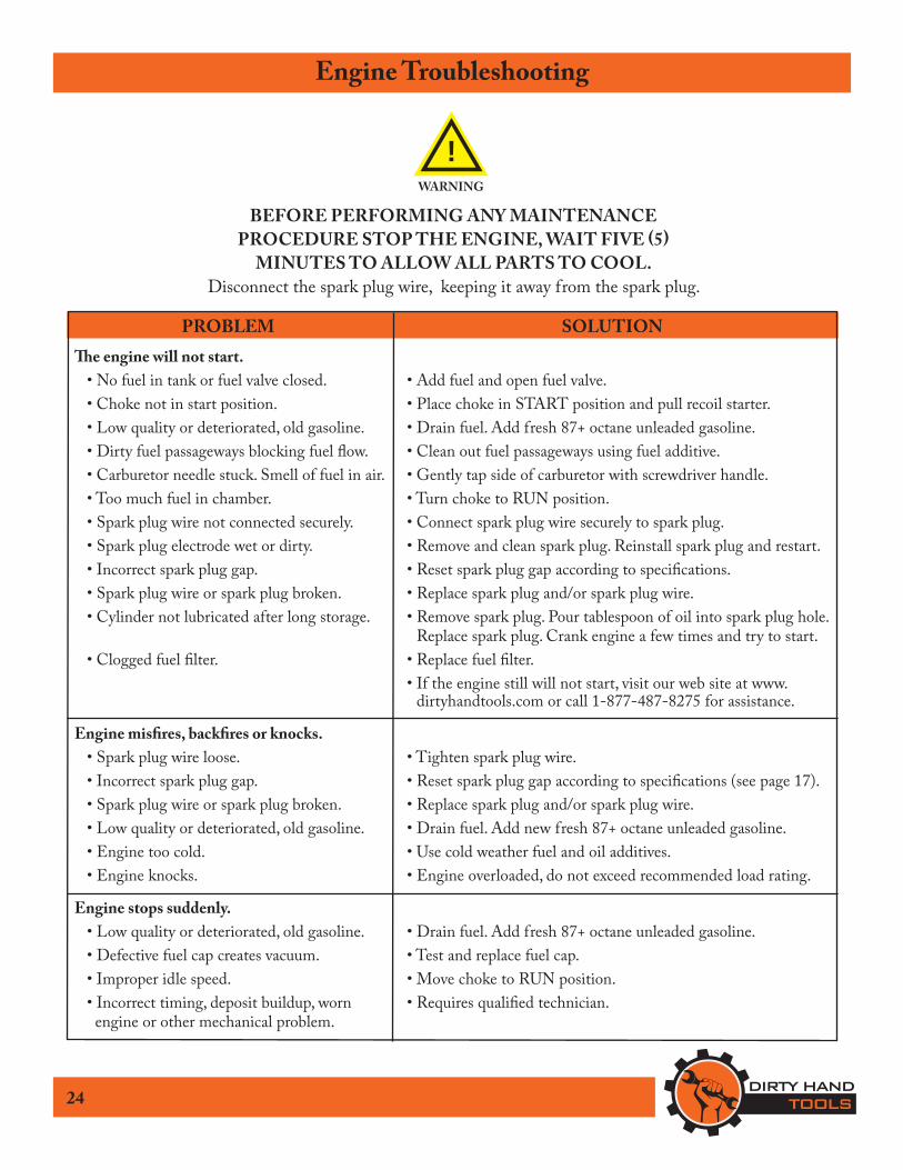
PROBLEM SOLUTION�e engine will not start. • No fuel in tank or fuel valve closed. • Add fuel and open fuel valve. • Choke not in start position. • Place choke in START position and pull recoil starter. • Low quality or deteriorated, old gasoline. • Drain fuel. Add fresh 87+ octane unleaded gasoline. • Dirty fuel passageways blocking fuel flow. • Clean out fuel passageways using fuel additive. • Carburetor needle stuck. Smell of fuel in air. • Gently tap side of carburetor with screwdriver handle. • Too much fuel in chamber. • Turn choke to RUN position. • Spark plug wire not connected securely. • Connect spark plug wire securely to spark plug. • Spark plug electrode wet or dirty. • Remove and clean spark plug. Reinstall spark plug and restart. • Incorrect spark plug gap. • Reset spark plug gap according to specifications. • Spark plug wire or spark plug broken. • Replace spark plug and/or spark plug wire. • Cylinder not lubricated after long storage. • Remove spark plug. Pour tablespoon of oil into spark plug hole.
Replace spark plug. Crank engine a few times and try to start. • Clogged fuel filter. • Replace fuel filter. • If the engine still will not start, visit our web site at www.
dirtyhandtools.com or call 1-877-487-8275 for assistance.
Engine mis�res, back�res or knocks. • Spark plug wire loose. • Tighten spark plug wire. • Incorrect spark plug gap. • Reset spark plug gap according to specifications (see page 17). • Spark plug wire or spark plug broken. • Replace spark plug and/or spark plug wire. • Low quality or deteriorated, old gasoline. • Drain fuel. Add new fresh 87+ octane unleaded gasoline. • Engine too cold. • Use cold weather fuel and oil additives. • Engine knocks. • Engine overloaded, do not exceed recommended load rating.
Engine stops suddenly. • Low quality or deteriorated, old gasoline. • Drain fuel. Add fresh 87+ octane unleaded gasoline. • Defective fuel cap creates vacuum. • Test and replace fuel cap. • Improper idle speed. • Move choke to RUN position. • Incorrect timing, deposit buildup, worn • Requires qualified technician. engine or other mechanical problem.
BEFORE PERFORMING ANY MAINTENANCE PROCEDURE STOP THE ENGINE, WAIT FIVE (5)
MINUTES TO ALLOW ALL PARTS TO COOL.Disconnect the spark plug wire, keeping it away from the spark plug.
!WARNING

25
Snow �rower Troubleshooting
PROBLEM SOLUTIONNo snow through thrower’s discharge chute. • Discharge chute and/or auger is clogged • Disengage the auger and drive controls, stop the engine, wait
ten seconds for the auger to stop rotating, then using the clean-out tool provided, remove the snow clogging the chute.
• Auger is not rotating • Shear pin(s) are missing or broken and need to be replaced.
Snow not completely removed from surface • Skid shoe needs adjustment • Disengage the auger and drive controls, stop the engine, wait
ten seconds for the auger to stop rotating. Loosen the two hex nuts on the skid show on either side of the snow thrower. Raise the skid shoes so the entire bottom surface of the skid show rests on the ground evenly. Retighten the hex nuts on both sides. �is adjustment allows the auger to come into closer contact with the ground surface.
Snow not evenly removed from surface • Tires not inflated evenly • Check tire pressure, inflate both tires to the same pressure
recommended (15-20 psi) so auger is level on the ground.
• Skid shoes not correctly adjusted • Make sure that skid shoes are at same height.
Cannot adjust the discharge chute • Moving parts are frozen • In extreme cold environments some controls and moving
parts may freeze. Do not use excessive force to operate frozen controls. Allow the engine to run for several minutes to warm up and thaw frozen parts.
Snow thrower continually clogs • Machine does not propel itself forward • Operate at a slower pace to allow the snow thrower to dispel
snow through the discharge chute. Forcing the snow thrower to move faster than it can remove the snow will result in clogged auger and/or discharge chute. Do not overload the thrower in extremely heavy or wet snow.

26
Snow �rower Troubleshooting
PROBLEM SOLUTIONAuger does not engage. • Auger control wire is too loose. • If there is too much slack in the auger control wire, the
augers will not be engaged properly. Turn off the engine. Adjust the tension of the auger control wire (see page 23).
• Auger is not rotating. • Shear pin(s) are missing or broken and need to be replaced.
• Auger belt is off the pulley, broken or worn. • Turn off the engine and allow to cool down for several minutes. Put the auger belt back on the pulley or replace the belt as needed. (See page 21).
Snow thrower does not propel itself.Drive control does not engage. • Drive control wire is too loose. • If there is too much slack in the drive control wire, the drive
will not be engaged properly. Turn off the engine. Adjust the the tension of the drive control wire (see page 23).
• Drive belt is off the pulley, broken or worn. • Turn off the engine and allow to cool down for several minutes. Put the drive belt back on the pulley or replace the belt as needed. (See page 22).
• Friction wheel is worn. • Refer to a qualified service technician for friction wheel replacement.
Snow thrower vibrates excessively. • Damaged auger or loose parts. • Turn off the engine and allow to cool down for several
minutes. Disconnect the spark plug wire. Examine the auger, replace shear pins if missing or broken, tighten all connecting bolts. If excessive vibration continues have the snow thrower serviced by a qualified technician.
Storage
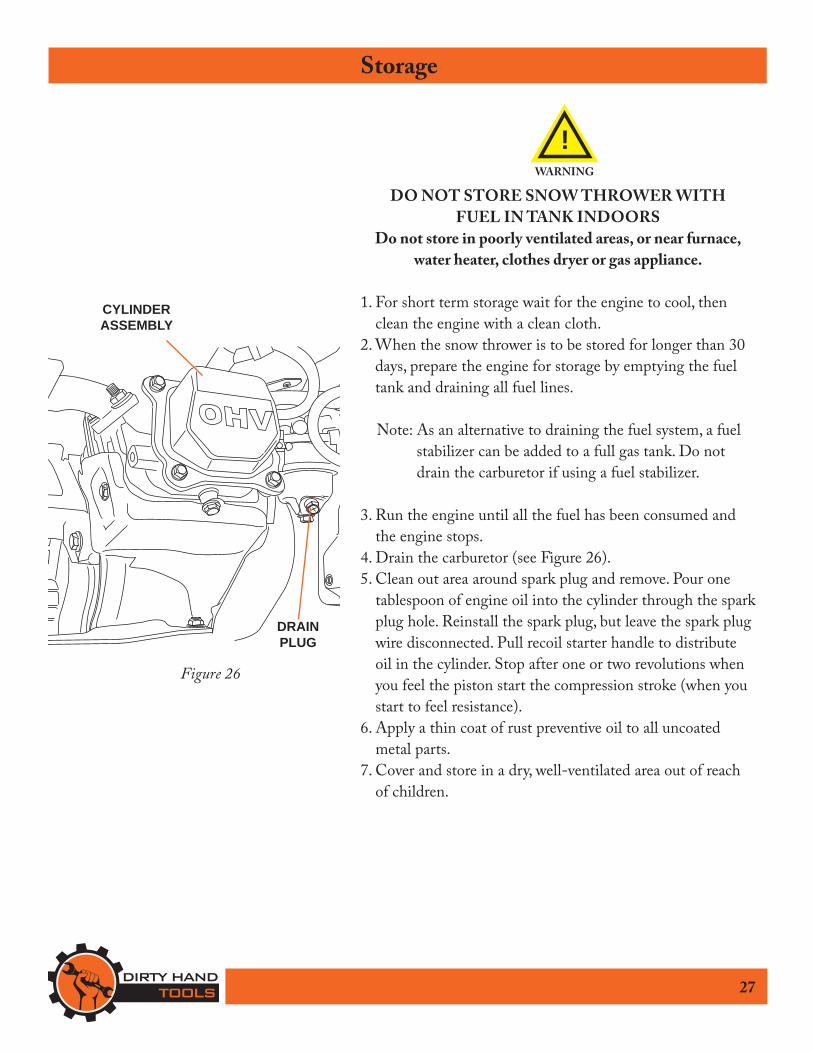
DO NOT STORE SNOW THROWER WITH FUEL IN TANK INDOORS
Do not store in poorly ventilated areas, or near furnace, water heater, clothes dryer or gas appliance.
1. For short term storage wait for the engine to cool, then clean the engine with a clean cloth.
2. When the snow thrower is to be stored for longer than 30 days, prepare the engine for storage by emptying the fuel tank and draining all fuel lines.
Note: As an alternative to draining the fuel system, a fuel stabilizer can be added to a full gas tank. Do not drain the carburetor if using a fuel stabilizer.
3. Run the engine until all the fuel has been consumed and the engine stops.
4. Drain the carburetor (see Figure 26).5. Clean out area around spark plug and remove. Pour one
tablespoon of engine oil into the cylinder through the spark plug hole. Reinstall the spark plug, but leave the spark plug wire disconnected. Pull recoil starter handle to distribute oil in the cylinder. Stop after one or two revolutions when you feel the piston start the compression stroke (when you start to feel resistance).
6. Apply a thin coat of rust preventive oil to all uncoated metal parts.
7. Cover and store in a dry, well-ventilated area out of reach of children.
27
Figure 26
CYLINDERASSEMBLY
DRAINPLUG
!WARNING

Warranty & Speci�cations IMPORTANT NOTICEWe, the manufacturer, reserve the right to change the product and/or specifications in this manual without notification. �e manual is for information usage only and the pictures and drawings depicted herein are for reference only.
Warranty Repair and ServiceDo not return this product to the store for warranty issues or repair. Call our customer service department at 720-287-5182, 1-877-487-8275, or visit www.dirtyhandtools.com for the location of the nearest service center.
Record the information below for future reference.
Model No.Serial No.Date of PurchasePlace of Purchase
SKU/Part No. 101487
Description 21” Snow �rowerEngine 212cc*, Single cylinder, 4-stroke, forced cooling,
OHV, EPA/CARB ApprovedTransmission 4 Forward, 1 Reverse SpeedsFuel Type Unleaded Gasoline, 87+ OctaneFuel Capacity 0.95 Gallon (3.6 Liters)Oil Capacity 1.27 Pints (0.6 Liters)Starting System RecoilSpark Plug Gap 0.028”~ 0.031”Chute Rotation Manual, 190° Turning RadiusMax. �rowing Distance 40 FeetWorking Width 21 inchesIntake Height 20 InchesDimensions 30”L x 23”W x 25”H
Weight 132 Lbs. Accessories Clean-Out Tool, Shear Pins
*As rated by engine manufacturer
Speci�cations
1100 W 120th Ave., Suite 600Westminster, CO 80234 • 720-287-5182
Dirty Hand Tools® is a brand of For Service or QuestionsCall 1-877-487-8275720-287-5182www.dirtyhandtools.com