Type T Hydraulic Deadweight Tester Operation Manual
43
Type T Hydraulic Deadweight Tester Operation Manual plus Service Instructions and Parts Lists ETEK ® SENSORS, TEST & CBON Test Equipment Depot - 800.517.8431 - 99 Washington Street Melrose, MA 02176 - TestEquipmentDepot.com
Transcript of Type T Hydraulic Deadweight Tester Operation Manual
Type T Hydraulic Deadweight Tester Operation Manual
plus Service Instructions and Parts Lists
.\METEK®
SENSORS, TEST & CALIBRATION
Test Equipment Depot - 800.517.8431 - 99 Washington Street Melrose, MA 02176 - TestEquipmentDepot.com

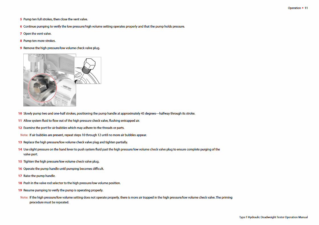
Contents
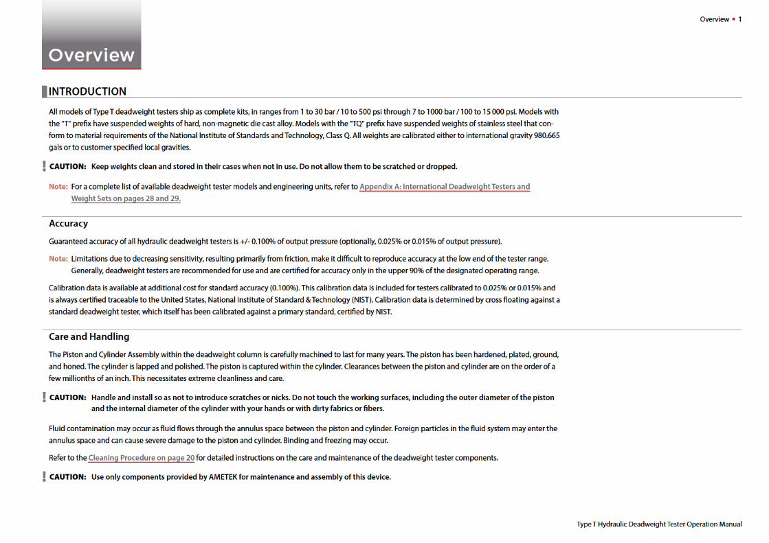
Overview . . . . . . . . . . . . . . . . . . . . . . . . . . . . . . . . . . . . . . . . . . . . . . . . . . . . . . . . . . . . . 1Introduction . . . . . . . . . . . . . . . . . . . . . . . . . . . . . . . . . . . . . . . . . . . . . . . . . . . . . . . . . . . . 1
Accuracy . . . . . . . . . . . . . . . . . . . . . . . . . . . . . . . . . . . . . . . . . . . . . . . . . . . . . . . . . . . . 1
Care and Handling . . . . . . . . . . . . . . . . . . . . . . . . . . . . . . . . . . . . . . . . . . . . . . . . . . . 1
Features and Parts Lists . . . . . . . . . . . . . . . . . . . . . . . . . . . . . . . . . . . . . . . . . . . . . . . . . 2
Parts Included with Type T Hydraulic Deadweight Testers . . . . . . . . . . . . . . . 2
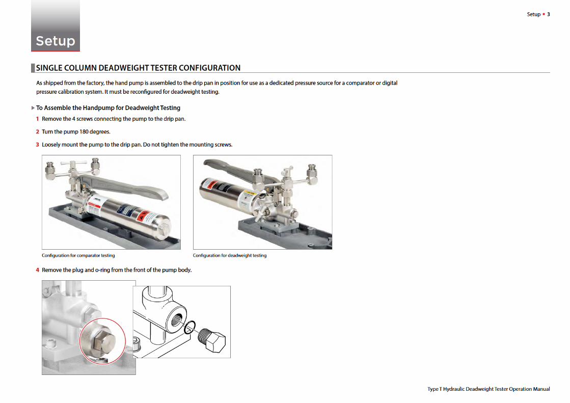
Setup . . . . . . . . . . . . . . . . . . . . . . . . . . . . . . . . . . . . . . . . . . . . . . . . . . . . . . . . . . . . . . . . . . 3Single Column Deadweight Tester Configuration . . . . . . . . . . . . . . . . . . . . . . . . . 3
Dual Column Deadweight Tester Configuration . . . . . . . . . . . . . . . . . . . . . . . . . . . 6
Operation . . . . . . . . . . . . . . . . . . . . . . . . . . . . . . . . . . . . . . . . . . . . . . . . . . . . . . . . . . . . 9Preparing to Generate Pressure . . . . . . . . . . . . . . . . . . . . . . . . . . . . . . . . . . . . . . . . . . 9
Priming . . . . . . . . . . . . . . . . . . . . . . . . . . . . . . . . . . . . . . . . . . . . . . . . . . . . . . . . . . . . . . . . 10
Adding Weight Masses . . . . . . . . . . . . . . . . . . . . . . . . . . . . . . . . . . . . . . . . . . . . . . . . . 12
Calibrating a Device Under Test . . . . . . . . . . . . . . . . . . . . . . . . . . . . . . . . . . . . . . . . . 12
Maintenance and Replacement . . . . . . . . . . . . . . . . . . . . . . . . . . . . . . . 15
Piston and Cylinder Assemblies . . . . . . . . . . . . . . . . . . . . . . . . . . . . . . . . . . . . . . . . . 15
The Optional Isolating Membrane . . . . . . . . . . . . . . . . . . . . . . . . . . . . . . . . . . . . . . . 18
Cleaning . . . . . . . . . . . . . . . . . . . . . . . . . . . . . . . . . . . . . . . . . . . . . . . . . . . . . . . . . . . . . . . 20
Specifications . . . . . . . . . . . . . . . . . . . . . . . . . . . . . . . . . . . . . . . . . . . . . . . . . . . . . . 21
Pressure Range . . . . . . . . . . . . . . . . . . . . . . . . . . . . . . . . . . . . . . . . . . . . . . . . . . . . . 21
Recommended Test Fluids . . . . . . . . . . . . . . . . . . . . . . . . . . . . . . . . . . . . . . . . . . . 21
Pressure Connections . . . . . . . . . . . . . . . . . . . . . . . . . . . . . . . . . . . . . . . . . . . . . . . 21
Physical Specifications . . . . . . . . . . . . . . . . . . . . . . . . . . . . . . . . . . . . . . . . . . . . . . 21
Support . . . . . . . . . . . . . . . . . . . . . . . . . . . . . . . . . . . . . . . . . . . . . . . . . . . . . . . . . . . . . . 22
Troubleshooting . . . . . . . . . . . . . . . . . . . . . . . . . . . . . . . . . . . . . . . . . . . . . . . . . . . . . . . 22
Failure to Pump . . . . . . . . . . . . . . . . . . . . . . . . . . . . . . . . . . . . . . . . . . . . . . . . . . . . . 22
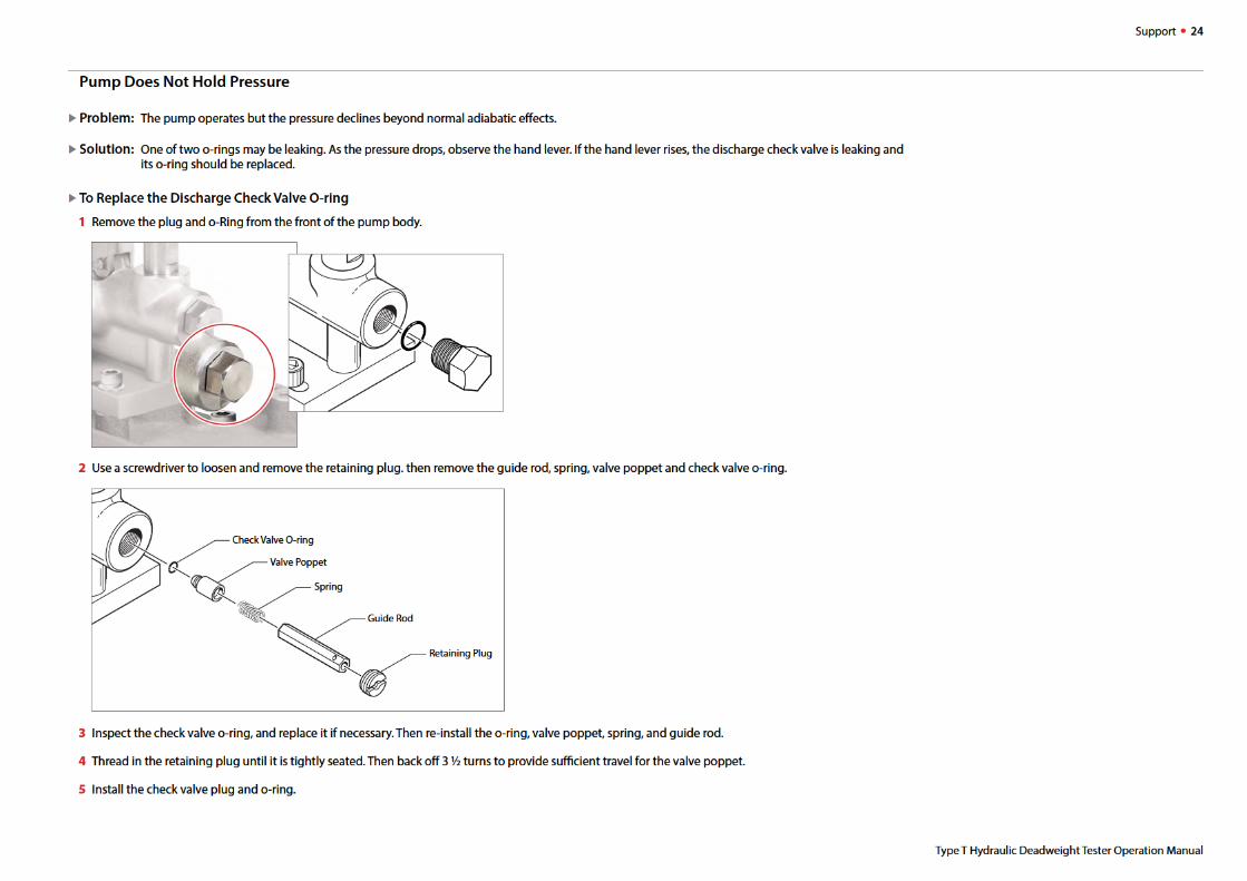
Pump Does Not Hold Pressure . . . . . . . . . . . . . . . . . . . . . . . . . . . . . . . . . . . . . . . 24
Fitting Kits and Spare Parts . . . . . . . . . . . . . . . . . . . . . . . . . . . . . . . . . . . . . . . . . . . . . 26
Service Kits . . . . . . . . . . . . . . . . . . . . . . . . . . . . . . . . . . . . . . . . . . . . . . . . . . . . . . . . . 26
Hoses . . . . . . . . . . . . . . . . . . . . . . . . . . . . . . . . . . . . . . . . . . . . . . . . . . . . . . . . . . . . . . 26
Adapters . . . . . . . . . . . . . . . . . . . . . . . . . . . . . . . . . . . . . . . . . . . . . . . . . . . . . . . . . . . 26
Recommended Recertification Procedures . . . . . . . . . . . . . . . . . . . . . . . . . . . . . . 26
Frequency of Recertification . . . . . . . . . . . . . . . . . . . . . . . . . . . . . . . . . . . . . . . . . 27
Certification Options for New and Used Deadweight Testers . . . . . . . . . . . 27
Appendices . . . . . . . . . . . . . . . . . . . . . . . . . . . . . . . . . . . . . . . . . . . . . . . . . . . . . . . . . . . . 28
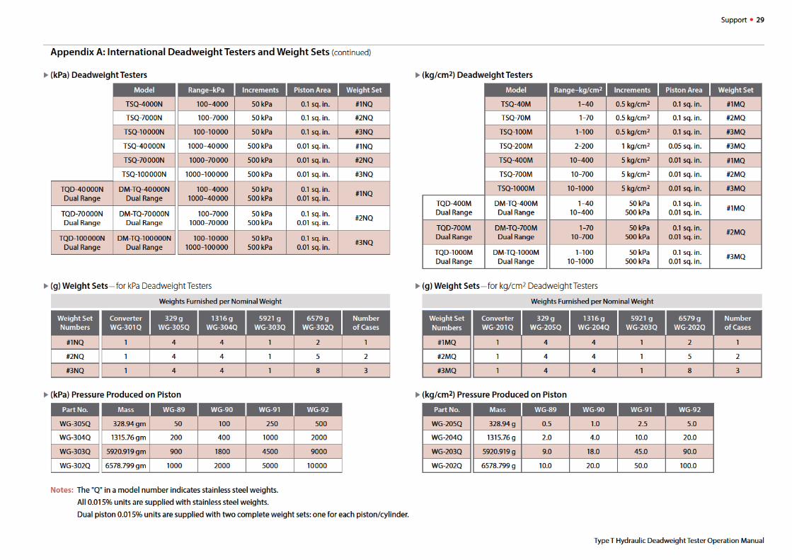
Appendix A: International Deadweight Testers and Weight Sets . . . . . . . 28
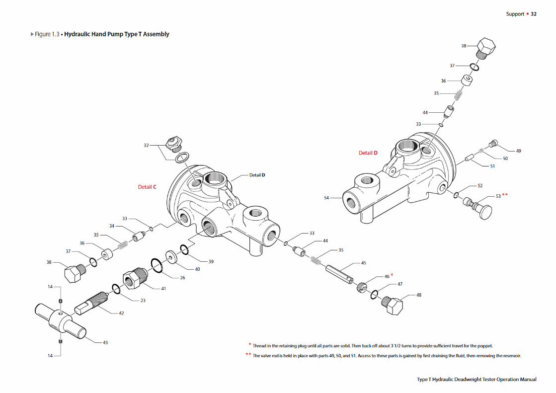
Appendix B: Assembly Drawings and Parts Lists . . . . . . . . . . . . . . . . . . . . . . . 30
Contact Us . . . . . . . . . . . . . . . . . . . . . . . . . . . . . . . . . . . . . . . . . . . . . . . . . . . . . . . . . . . . . 40
Returning product to AMETEK . . . . . . . . . . . . . . . . . . . . . . . . . . . . . . . . . . . . . . . . . . 40
Warranty . . . . . . . . . . . . . . . . . . . . . . . . . . . . . . . . . . . . . . . . . . . . . . . . . . . . . . . . . . . . . . 40


Setup 5
Type T Hydraulic Deadweight Tester Operation Manual
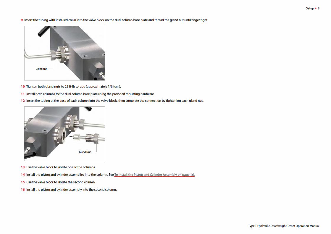
9 Align the union body (attached to the column) with the union nipple and nut on the front of the pump body.
10 Carefully finger-tighten the union nut to the union body.
Align the connecting hardware… then finger-tighten the union nut.
11 Ensure again that the column-to-pump connecting hardware is in alignment, then apply a back-up wrench to the union nipple.
12 Using a second wrench, tighten the union nut onto the threads of the union body.
13 Tighten the pressure connections between the pump body and the column assembly.
14 Tighten the screws securing the column to the drip pan.
15 Tighten the mounting screws securing the pump to the drip pan.
! CAUTION: Deadweight testers should be bolted to a workbench or table to prevent tipping.
Union Nipple and Nut
Union Body Union Nut
Union Nipple
Union Nut
Test Equipment Depot - 800.517.8431 - 99 Washington Street Melrose, MA 02176 - TestEquipmentDepot.com


Operation • 9
I PREPARING TO GENERATE PRESSURE
1 Close the vent valve.
Note: It may be necessary to prime the pump, particularly for first time use, or if the pump has been inactive for an extended period of time.
Refer to Priming on page 10 for instructions on priming the pump.
2 Pull the pump handle to the top of its stroke.
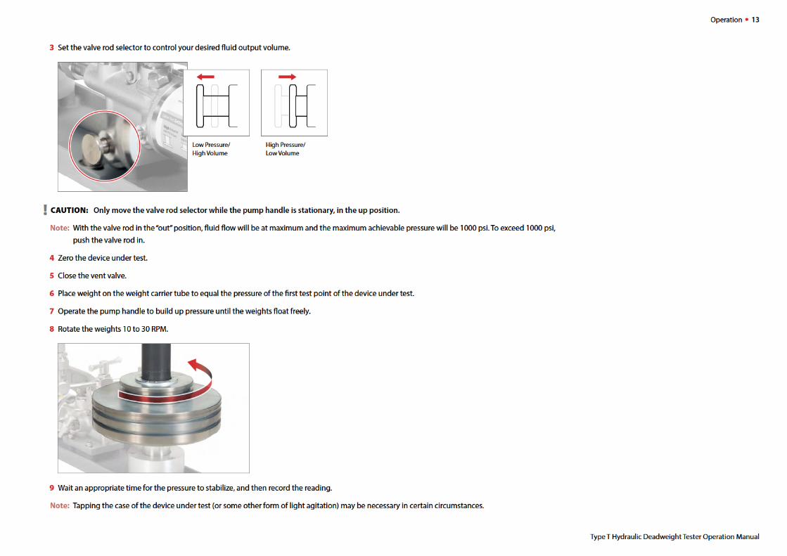
3 Pull out the valve rod selector to select the low pressure/high volume setting.
Type T Hydraulic Deadweight Tester Operation Manual
Test Equipment Depot - 800.517.8431 - 99 Washington Street Melrose, MA 02176 - TestEquipmentDepot.com


I ADDING WEIGHT MASSES
Weight masses are suspended from the weight carrier tube, which is suspended from the piston assembly. Weight placed on the weight carrier tube should
be equal to between 90% and 100% of the range of the device under test.
Note: A piston assembly, in combination with a weight carrier tube, will produce its own pressure (based on its force and mass). That pressure needs to
be factored in when deciding how much weight to add to the carrier tube. Refer to the Pressure Produced on Piston tables on pages 28 and 29 for
pressure produced by the different piston assemblies.
For example, to obtain 145 psi, using a 1/10 square inch area piston, the following weights would be added onto the weight carrier tube:
• (1) grooved 9" diameter weight: WG-26 ... 95 psi
• (2) 6" diameter weights: WG-25 ........... 40 psi
• (1) 3 1 /2" diameter weight: WG-23 ......... 5 psi
Subtotal ......... 140 psi
• 1/10 square inch area piston .............. 5 psi
and weight carrier tube
Total ........ 145 psi
ICALIBRATING A DEVICE UNDER TEST
1 Check that the vent fill plug is fully open by turning it counter-clockwise.
2 Open the vent valve.
Open the vent plug ... then open the vent valve.
Operation • 12
Type T Hydraulic Deadweight Tester Operation Manual
Test Equipment Depot - 800.517.8431 - 99 Washington Street Melrose, MA 02176 - TestEquipmentDepot.com
10 Repeat steps 7 through 9, adding weight to equal the pressures of the remaining test points for the device under test, and recording each reading.
If hysteresis performance is desired, proceed to step 11.
If hysteresis performance is not desired, proceed to step 16.
11 Remove weight from the weight carrier tube to equal the pressure of the first descending test point for the device under test.
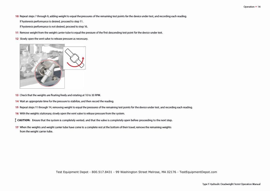
12 Slowly open the vent valve to release pressure as necessary.
13 Check that the weights are floating freely and rotating at 10 to 30 RPM.
14 Wait an appropriate time for the pressure to stabilize, and then record the reading.
1 S Repeat steps 11 through 14, removing weight to equal the pressures of the remaining test points for the device under test, and recording each reading.
16 With the weights stationary, slowly open the vent valve to release pressure from the system.
! CAUTION: Ensure that the system is completely vented, and that the valve is completely open before proceeding to the next step.
17 When the weights and weight carrier tube have come to a complete rest at the bottom of their travel, remove the remaining weights
from the weight carrier tube.
Operation • 14
Type T Hydraulic Deadweight Tester Operation Manual
Test Equipment Depot - 800.517.8431 - 99 Washington Street Melrose, MA 02176 - TestEquipmentDepot.com


Maintenance and Replacement 18
Type T Hydraulic Deadweight Tester Operation Manual
� THE OPTIONAL ISOLATING MEMBRANE
An optional isolating membrane is available for installation on all deadweight tester models. The isolating membrane:
• Isolates harmful dirt particles, originating in the system being calibrated and/or the pump, from the piston cylinder.
• Allows the use of MGAAA instrument oil in contact with the piston-cylinder assembly which will reduce the rate of fluid leakage through that assembly. This reduces the frequency of the pumping required to maintain the piston in the referenced calibration plane.
! CAUTION: Use only MGAAA oil provided by M&G for the isolating membrane. The AAA designation means that it is triple filtered for suspended solids.
! CAUTION: Do not allow the parts exposed in the following steps to come into contact with dirt, debris, or fine particles of any kind.
X To Install the Isolating Membrane
Once the piston and cylinder assembly has been removed, the optional isolating membrane may be installed.
1 Remove the piston and cylinder assembly.
See To Remove the Piston and Cylinder Assembly on page 15.
2 Remove the piston from the cylinder.
3 Remove the o-ring from the cylinder and set it aside.
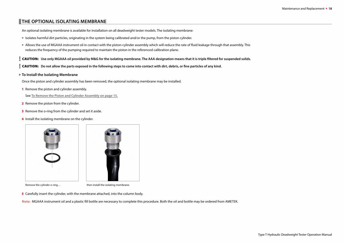
4 Install the isolating membrane on the cylinder.
Remove the cylinder o-ring… then install the isolating membrane.
5 Carefully insert the cylinder, with the membrane attached, into the column body.
Note: MGAAA instrument oil and a plastic fill bottle are necessary to complete this procedure. Both the oil and bottle may be ordered from AMETEK.

6 Push the capillary tube of the instrument oil bottle through the center of the cylinder, into the isolating membrane.
7 Squeeze the oil bottle to fill the membrane up to the bottom of the cylinder bore.
8 Using the hand pump, carefully pump fluid into the column to compress the membrane and bring its fluid level to the top of the cylinder.
9 Coat the piston with a light film of MGMA oil.
10 Using care not to force, damage, or bend the piston, carefully work the piston down into the cylinder bore while simultaneously releasing pump pressure
with the Pressure Vent Valve so that the piston will enter the cylinder bore without any trapped air.
11 Replace the cylinder cap.
12 Install the eight (8) socket head cap screws and tighten alternately to 30 inch-lb.
Note: To operate with the required degree of sensitivity, there must be a controlled clearance between the cylinder bore and piston. Therefore, there will be
some leakage of fluid through this annulus area. The loss of fluid will depend on the length of the test period, the range of pressure determinations,
and the test conditions. The amount of fluid in the isolating membrane should be checked periodically.
Maintenance and Replacement • 19
Type T Hydraulic Deadweight Tester Operation Manual
Test Equipment Depot - 800.517.8431 - 99 Washington Street Melrose, MA 02176 - TestEquipmentDepot.com

Maintenance and Replacement 20
Type T Hydraulic Deadweight Tester Operation Manual
� CLEANING
Each M&G piston and cylinder assembly is tested within very close tolerances during manufacture for pressure retention (leak rate), for sensitivity, and for ac-
curacy of calibration. Each assembly is then cleaned, identified by a serial number and stored until shipped.
! CAUTION: A piston and cylinder assembly is a very closely fitted assembly. Clearances between the piston and cylinder are on the order of 5 to 20 millionths of an inch. Such clearances require utmost cleanliness for satisfactory operation.
X To Clean the Piston and Cylinder Assembly
! CAUTION: Extremely small particles can cause trouble in this closely fitted assembly. Take extreme care to ensure cleanliness.
1 Carefully wipe off any visible dirt or foreign matter from the protruding part of the piston and slowly withdraw the piston from the cylinder.
! CAUTION: Do not use force, but be sure all dirt is removed so the piston will slip out easily.
2 The cylinder bore should be wiped with a small, soft-handled wiper such as a cotton swab to remove all evidence of dirt.
3 Wipe the piston dry and clean with a lint free wiper, such as a lint free cloth.
4 Rinse the piston and cylinder in a residual free solvent.
5 Wipe the cylinder bore and piston again to remove any dirt.
6 Pick up the piston by the piston cap.
7 Dip it in clean test fluid.
8 Carefully insert the piston in the cylinder.
! CAUTION: Repeat this cleaning procedure if you notice any roughness or grit in the annulus area while re-inserting the piston.
9 The deadweight column in which the piston is to be mounted should be drained and flushed with a solvent such as ethyl alcohol, then cleaned, dried, and
refilled using clean test fluid.
See To Install the Piston and Cylinder Assembly on page 16 to install the piston and cylinder assembly into a column.


I TROUBLESHOOTING
Failure to Pump
► Problem: The pump fails to develop pressure when the hand lever is operated.
► Solution: Verify that the vent valve is closed and that there is sufficient fluid in the reservoir. If necessary, add fluid through the fill plug and follow the Pump
Priming Procedure.
If the failure continues, one or both of the check valves may be leaking. Use the following procedure to replace both the high pressure and low pressure o-rings.
► To Replace the Check Valve O-rings
1 Raise the pump handle to the top of its stroke.
2 Position the valve rod selector for the o-ring you wish to replace.
(a) Pull out the valve rod selector to select the low pressure/high volume setting.
(b) Push in the valve rod selector to select the high pressure/low volume setting.
3 Remove the plug and o-ring from the port for the check valve o-ring you wish to replace.
Low pressure/high volume check valve plug and o-<ing. High pressure/low volume check valve plug and o-ring.
Support • 22
Type T Hydraulic Deadweight Tester Operation Manual
Test Equipment Depot - 800.517.8431 - 99 Washington Street Melrose, MA 02176 - TestEquipmentDepot.com


► To Replace the Vent Valve 0-ring
1 Apply a wrench to the nut at the base of the pressure relief valve.
2 Remove the vent valve and its o-ring.
3 Remove the relief valve seat and its o-ring.
Relief Valve Seat 0-ring �
Relief Valve Seat � �
�
4 Inspect the relief valve seat o-ring, and replace it if necessary. Then re-install the o-ring, valve poppet, spring, and guide rod.
S Install the vent valve and o-ring.
Support • 25
Type T Hydraulic Deadweight Tester Operation Manual
Test Equipment Depot - 800.517.8431 - 99 Washington Street Melrose, MA 02176 - TestEquipmentDepot.com

Support 26
Type T Hydraulic Deadweight Tester Operation Manual
� FITTING KITS AND SPARE PARTS
Service Kits
X T-1T-250 . . . . . . . . . . . . . Buna N rebuild kit
T-559 . . . . . . . . . . . . . Viton rebuild kit
T-326 . . . . . . . . . . . . . EPT rebuild kit
Hoses
X T-1KH-18 . . . . . . . . . . . . Hose. 0.46 m 1/4" NPT male x 1/4" NPT male 700 bar / 10 000 psi.
Adapters
X T-1T-134 . . . . . . . . . . . . . Union Body. 15/16-20 UNEF male x 1/4" NPT female.
T-135 . . . . . . . . . . . . . Union Body. 15/16-20 UNEF male x 1/2" NPT female.
T-186 . . . . . . . . . . . . . Union Body. 15/16-20 UNEF male x 7/16" NPT female.
T-331 . . . . . . . . . . . . . Union Body. 15/16-20 UNEF male x 3/8" NPT female.
T-863 . . . . . . . . . . . . . Union Body. 15/16-20 UNEF male x 1/8" NPT female.
T-786 . . . . . . . . . . . . . Adapter. 1/4" NPT male x 1/4" BSP female.
T-787 . . . . . . . . . . . . . Adapter. 1/4" NPT male x 1/2" BSP female.
T-915 . . . . . . . . . . . . . Quick Connector. 1/4" NPT male.
T-916 . . . . . . . . . . . . . Quick Connector Plug. 1/4" NPT male.
� RECOMMENDED RECERTIFICATION PROCEDURES
All deadweight pressure testers produced by AMETEK, M&G are tested and certified in the M&G laboratory for accuracy of pressure produced, with results
traceable to the National Institute of Standards and Technology.
In addition, if ±0.025% or ±0.015% accuracy is required, data is furnished showing nominal and observed pressures within the upper 90% of the range of
each piston and cylinder, with results directly traceable to the National Institute of Standards and Technology.
Note: This data is optional on the ±0.010% units.
This accuracy can degrade with wear resulting from continued use and/or incidental damage. AMETEK, M&G recommends all instruments be periodically
retested for accuracy. Testers returned to AMETEK, M&G will be “Tested and re-certified with data furnished traceable to NIST.”


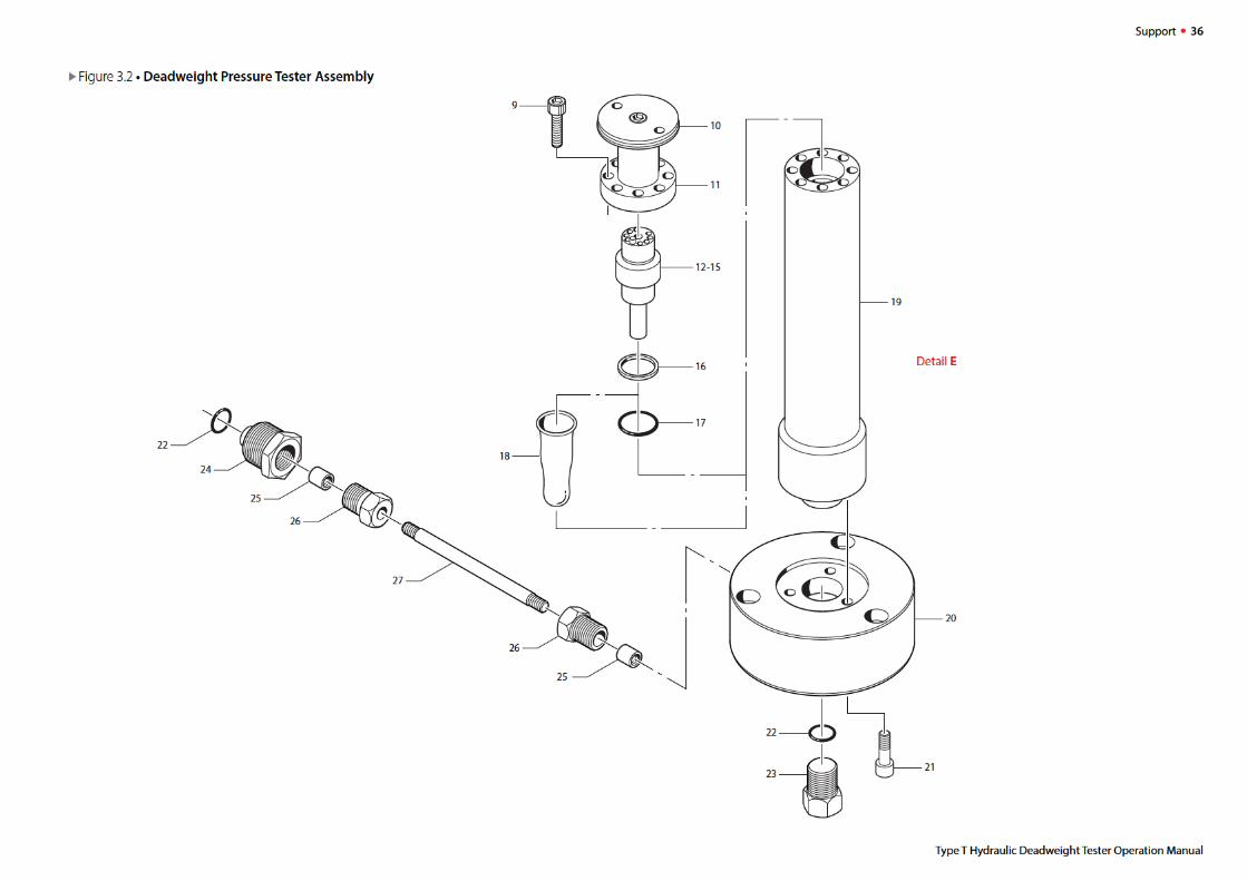

► Figure 3.3. Deadweight Pressure Tester Assembly Parts List
2
3
4
s
s
6
6
7
7
8
8
9
10
11
12
13
14
15
16
17
18
19
20
21
22
23
24
25
Part . . Units Per Number Description Assembly
T-137 Indicator, Weight Position
T-178 Nut, Indicator
01-90016 Screw, Column Base Attaching 3
WG-53 Tube, Weight Carrier
WG-23 Weight-0.5 lb. Kirksite *
WG-23Q Weight-0.5 lb. Brass *
WG-25 Weight-2 lbs. Kirksite *
WG-25Q Weight-2 lbs. Brass *
WG-26 Weight-9.5 lbs. Kirksite *
WG-26Q Weight-9.5 lbs. Brass *
WG-27 Weight-10 lbs. Kirksite *
WG-27Q Weight-10 lbs. Brass *
01-90038 Screw, Cylinder Clamping 8
WG-56 Tube Carrier Assembly
WG-52 Cap, Cylinder
WG-89 Piston and Cylinder Assembly-1/10 Area *
WG-90 Piston and Cylinder Assembly-l/2-0Area *
WG-91 Piston and Cylinder Assembly- 1/so Area *
WG-92 Piston and Cylinder Assembly-1/100 Area *
10-90039 Back-up Ring, Cylinder (WG-108) *
10-90015 O-ring, Cylinder (WG-111) *
WG-109 Membrane, Elastomer (Optional)
WG-28 Body, Column
T-244 Base, Column
01-90002 Screw, Column Body Attaching 3
10-90027 O-ring (T-154) 2
T-117 Plug, Column
T-245 Body,Union
WG-140 Collar, Nipple 2
* For Weight Set and Piston and Cylinder Assembly options refer to Appendix A on pages 28-29.
26
27
Part . . Units Per Number Description Assembly
WG-139 Male Gland, Nipple 2
T-246 Nipple, Pump Connecting
T-177 Case, Carrying
T-222 Case, Weight Carrying **
WG-67 Case, Weight Carrying **
Support • 37
** Carrying Cases will be provided based on the Weight Set(s) selected.
Type T Hydraulic Deadweight Tester Operation Manual
Test Equipment Depot - 800.517.8431 - 99 Washington Street Melrose, MA 02176 - TestEquipmentDepot.com


Support 40
Type T Hydraulic Deadweight Tester Operation Manual
� CONTACT US
� WARRANTY
This instrument is warranted against defects in workmanship, material and design for one (1) year from date of delivery to the extent that AMETEK will, at its sole
option, repair or replace the instrument or any part thereof which is defective, provided, however, that this warranty shall not apply to instruments subjected to
tampering or, abuse, or exposed to highly corrosive conditions.
THIS WARRANTY IS IN LIEU OF ALL OTHER WARRANTIES WHETHER EXPRESS OR IMPLIED AND AMETEK HEREBY DISCLAIMS ALL OTHER WARRANTIES, INCLUDING,
WITHOUT LIMITATION, ANY WARRANTY OF FITNESS FOR A PARTICULAR PURPOSE OR MERCHANTABILITY. AMETEK SHALL NOT BE LIABLE FOR ANY INCIDENTAL
OR CONSEQUENTIAL DAMAGES, INCLUDING, BUT NOT LIMITED TO, ANY ANTICIPATED OR LOST PROFITS.
This warranty is voidable if the purchaser fails to follow any and all instructions, warnings or cautions in the instrument’s Instruction Manual.
If a manufacturing defect is found, AMETEK will replace or repair the instrument or replace any defective part thereof without charge; however, AMETEK’s obliga-
tion hereunder does not include the cost of transportation, which must be borne by the customer. AMETEK assumes no responsibility for damage in transit, and
any claims for such damage should be presented to the carrier by the purchaser.
Test Equipment Depot - 800.517.8431 - 99 Washington Street Melrose, MA 02176 - TestEquipmentDepot.com

.\METEK®
SENSORS, TEST & CALIBRATION
Fonn N' 68-23 rev 14