Stauff Hydraulic Tester PPC 06/08 · PDF fileStauff Hydraulic Tester PPC 06/08 plus Manual...
49
1 Stauff Hydraulic Tester PPC 06/08 plus Manual Version 1.0 Part number: 1810000267
Transcript of Stauff Hydraulic Tester PPC 06/08 · PDF fileStauff Hydraulic Tester PPC 06/08 plus Manual...
1
Stauff Hydraulic Tester
PPC 06/08 plusManual
Version 1.0Part number: 1810000267

2
Contact addressWalter Stauffenberg GmbH & Co. KGPostfach 1745 58777 WerdohlIm Ehrenfeld 4 58791 WerdohlGermany
Phone: +49 2392 916-0Fax: +49 2392 2505E-Mail: [email protected]: www.stauff.com
Version 1.0April 2009

3
Contents
1.0 Notes on safety / Product selection.................................................................. 51.1. Approved use ............................................................................................... 51.2. Skilled Personnel.......................................................................................... 51.3. Accuracy of the technical documentation ..................................................... 51.4. High-pressure applications........................................................................... 51.5. Service / Repair............................................................................................ 61.6. Notes on disposal......................................................................................... 6
2.0 Device version / Scope of delivery................................................................... 73.0 Initial use.......................................................................................................... 8
3.1. Charging the batteries / Battery status inidcator........................................... 84.0 Keys and Functions ......................................................................................... 9
4.1. Keys and Functions...................................................................................... 94.2. Function Keys and Menu Keys................................................................... 104.3. Symbols and using the menus ................................................................... 114.4. What the function keys do within the menus .............................................. 11
5.0 Connecting the sensors / Display functions ................................................... 125.1. Display format (DISP)................................................................................. 135.2. Display Configuration (LINE)...................................................................... 145.3. Zero Point Calibration (ZERO) ................................................................... 155.4. Deleting MIN / MAX values (RESET) ......................................................... 165.5. Difference for measuring values................................................................. 165.6. Differential value alignment (IN1=IN2)........................................................ 175.7. Connecting auxiliary sensors (SET AUX: SENSOR).................................. 195.8. Error messages / Warnings........................................................................ 21
6.0 Device settings (SET) .................................................................................... 226.1. Setting the units (SET-UNIT)...................................................................... 236.2. Auto power off (SET-AUTO POWER) ........................................................ 236.3. Setting auxiliary sensors (SET-AUX.SENSOR).......................................... 236.4. Displaying defined measurement tasks (SET-PROJECT).......................... 246.5. Setting the contrast (SET-CONTRAST) ..................................................... 246.6. Setting the time / date (SET-TIME/DATE).................................................. 256.7. Displaying the device version (SET-VERSION) ......................................... 256.8. Factory setting (USER RESET).................................................................. 25
7.0 Configuring the measured value memory (MEMORY SET)........................... 267.1. Deleting the measured value memory (MEM-DELETE MEMORY) ............ 287.2. Setting the data format (MEM-DATA FORMAT)......................................... 287.3. Setting the recording format(MEM-REC-CONFIG)..................................... 28
8.0 The REC menu .............................................................................................. 299.0 Recording measured values .......................................................................... 31
9.1. Settings for recording measured values (REC) .......................................... 319.2. The REC NAMES setting ........................................................................... 329.3. Memory function START/STOP ................................................................. 339.4. Memory function POINT............................................................................. 359.5. Memory function AUTO TRIGGER............................................................. 379.6. Memory function MANUAL......................................................................... 399.7. Recording measured values with default PROJECT settings..................... 41

4
10.0 Setting and operating via PC...................................................................... 4210.1. Connecting to a PC .................................................................................... 4210.2. Operating / Configuring via PC................................................................... 42
11.0 Accessories................................................................................................ 4312.0 Technical Data ........................................................................................... 4413.0 Description of the memory functions .......................................................... 45

5
1.0 Notes on safety / Product selection
1.1. Approved use
The device is approved for use in applications described in the Operating instructions only.Any other use is not approved and can lead to accidents or the destruction of the device.Non-approved use will result in the immediate expiry of all guarantee and warranty claimsagainst the manufacturer.
Serious malfunctions leading to personal injury or damage to property canresult from using the chosen product in applications that do not comply withthe given specifications or from disregarding the operating instructions andwarning notes.
1.2. Skilled Personnel
These operating instructions have been written for skilled personnel who are familiar with thevalid regulations and standards applicable to the field of application.
1.3. Accuracy of the technical documentation
These operating instructions were created with the utmost care and attention. However, weoffer no guarantee that the data, graphics and drawings are correct or complete. Subject toalteration without notice.
1.4. High-pressure applications
SelectionWhen selecting pressure components, ensure that the overload pressure will not beexceeded.
It is possible that the pressure cell can be deformed when the overload pressure isexceeded (depending on the duration / frequency and level of the pressure spike).
The "diesel effect" caused by entrapped air can result in pressure spikes that farexceed the overload pressure. The nominal pressure of the pressure componentshould be higher than the nominal pressure of the system to be measured.

6
MountingPlease abide by the instructions and observe the correct tightening torques for thefittings or adapters being utilized:
Connector thread: ½" BSP = 90 Nm¼" BSP = 30 Nm
Please observe the highest pressures detailed in the catalogues for hydraulic hosesfrom the Walter Stauffenberg GmbH & Co. KG.
1.5. Service / Repair
For repairs to or calibration of the measurement instruments, please contact your localSTAUFF sales branch.
1.6. Notes on disposal
Recycling in accordance with WEEEPurchasing our product gives you the opportunity to return the device to STAUFF at the endof its life cycle.
The EU Directive 2002/96 EC (WEEE) regulates the return and recycling of wasteelectrical and electronics equipment.As of 13/08/2005 manufacturers of electrical and electronics equipment in the B2B(business-to-business) category are obliged to take back and recycle WEEE free ofcharge sold after this date. After that date, electrical equipment must not bedisposed of through the "normal" waste disposal channels. Electrical equipmentmust be disposed of and recycled separately. All devices that fall under the directivemust feature this logo:
Can we be assistance?The Walter Stauffenberg Company offers you the option of returning your old device to us atno extra charge. STAUFF will then professionally recycle and dispose of your device inaccordance with the applicable law.
What do you have to do?Once your device has reached the end of its service life, simply return it by parcel service (inthe box) to your STAUFF sales branch responsible for customer care – we will then initiatethe necessary recycling and disposal measures. You will incur no costs or suffer anyinconvenience.
Any questions?If you have any questions, please contact us or visit our website: www.stauff.com

7
2.0 Device version / Scope of delivery
According to your order the Walter Stauffenberg Company will supply you one of thefollowing devices:
PPC-06 plus device with 3 sensor inputsPPC-08 plus device with 4 sensor inputs
Every measurement device is supplied with the following components:
- Power supply PPC-04/12-110V/230V (110/230 V AC)- PC connection cable (USB)- Diagtronics-CD (incl. PC-software, manual and product catalogues
as files)
8
3.0 Initial use
The measuring instrument is supplied with rechargeable batteries fitted at the factory.
Charge the rechargeable batteries for at least 3 hours before using the first time.The device is then ready for use.
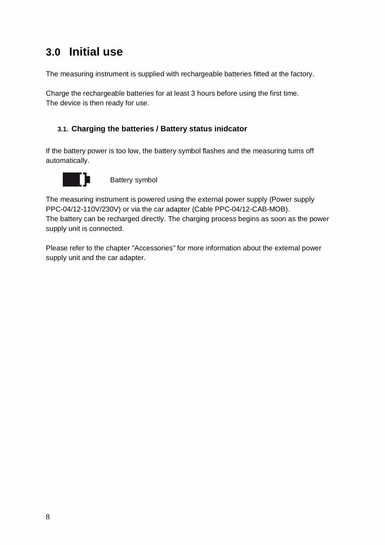
3.1. Charging the batteries / Battery status inidcator
If the battery power is too low, the battery symbol flashes and the measuring turns offautomatically.
Battery symbol
The measuring instrument is powered using the external power supply (Power supplyPPC-04/12-110V/230V) or via the car adapter (Cable PPC-04/12-CAB-MOB).The battery can be recharged directly. The charging process begins as soon as the powersupply unit is connected.
Please refer to the chapter "Accessories" for more information about the external powersupply unit and the car adapter.

9
4.0 Keys and Functions
4.1. Keys and Functions
A B
B
C
D
E
A 11-30VDCPower supply unit110/230 VAC-15 VDC orCar adapter cable 12/24 VDC
B I1 ... I3 (PPC-06 plus)I1 ... I4 (PPC-08 plus)Sensor ports
C PC (USB)Port for PC-cable(to USB)
D DisplayDisplaying the measurements
E KeypadMoving in the menus
ON/OFF
OK
DISP
ESC
REC
LINE
STOP
MEM
ZERO
RESETMIN/MAX
PPC-06-plus®

10
4.2. Function Keys and Menu Keys
Function Keys
ON / OFF
Confirms functions / values
Selects functions / values
STOP / ESC
Menu KeysThese keys are assigned dual functions:
Assignment 1. Menu level = 1 x pressAssignment 2. Menu level (black background) = 1 x hold key (2 seconds)
ZERO Zero point calibrationDifferential value alignment
MEM Memory configurationMain menu (Device Settings)
DISP MIN-MAX / ACTUAL or FS displayDisplay configuration
REC Record measurement values
Delete Deleting MIN / MAX values

11
4.3. Symbols and using the menus
If the sign ">" is displayed at the end of a menu function, press the "OK" key to enteran associated submenu.If the sign ":" is displayed, press the "OK" key to confirm the respective entry.
Menu symbol Key Function Example
>Call up a submenu /Setting
UNIT > .
: Confirm AUTO POWER : OFF
▲▼ Select --SET-- ▲▼
Key assignment and symbols associated with the menu functions are consistentthroughout this device; therefore will be no further explicit explanation given.
4.4. What the function keys do within the menus
Use the arrow keys to scroll between functions when several functions are available forselection in a window or a menu. The arrow keys move the cursor in the direction in whichthe arrow is pointing.
Press the "OK" key each time you wish to select a function or submenu; when makingalterations or adding values you must press "OK" to confirm your action. The "OK" key isused to save all settings.
Press the "STOP / ESC" key if you wish to leave a menu or do not wish to save an entry.
Key assignment and mode of operation of these three keys is always the same no matter inwhich menu they are used.
As the function keys are easy to understand and always function in the samemanner, actuating the function keys has not been included in the examplesequences to ensure that the content of the menus remain central to thedescriptions. It is a pre-condition for replicating the examples that the function keysare used as described above.

12
5.0 Connecting the sensors / Display functions
To avoid electrical interference, please observe the following steps:
1 Connect the sensor to the measuring instrument using the connection cable.2 Turn on the measuring instrument.
Measuring instrument with two pressure sensors
• Once turned on, all measured values are visible in the display.• Automatic sensor recognition ensures that the measured value is indicated in the
correct unit.• No further settings to the device are required.
• The following message will be displayed if no sensor is connected to the device.
ON/OFF
OK
DISP
ESC
REC
LINE
STOP
MEM
ZERO
RESETMIN/MAX
IN1=IN2
SET
11-30VDC I1 I2 I3
I4 PC
PPC-06-plus®

13
5.1. Display format (DISP)
Press DISP (once)
It is possible to change the display format bypressing DISP (once only).
Available selection:
ACT = Actual valuesMIN = Minimum valuesMAX = Maximum values (pressure spikes)FS = Full scale (upper range value)TEMP = Temperature display
The TEMP display applies only to the sensor type PPC-04/12-PT.

14
5.2. Display Configuration (LINE)
Press and hold (2 seconds)
Line:1: No settings possible; cannot be selected
2: Available for selection:Difference (IN1 – IN2)Addition (IN1 + IN2)
3: Volume VOL = Q3 x time
4: Available for selectionPowerPWR1 = p1 x Q3PWR2 = (p1-p2) x Q3
15
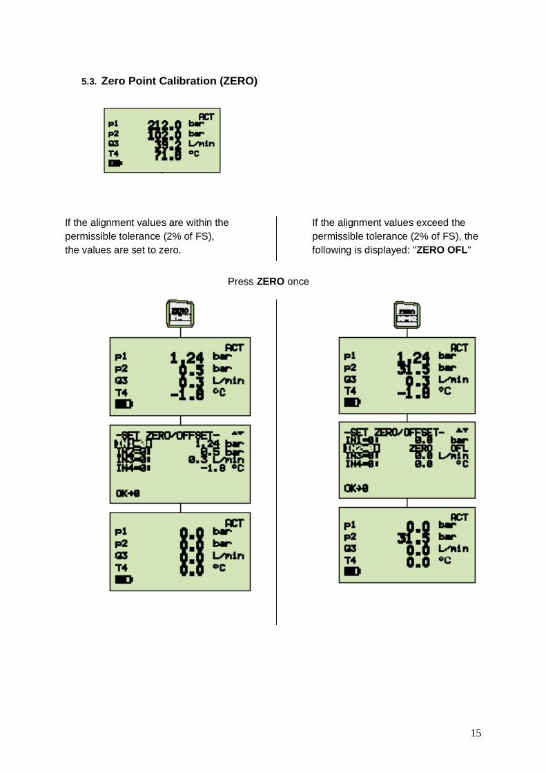
5.3. Zero Point Calibration (ZERO)
If the alignment values are within the If the alignment values exceed thepermissible tolerance (2% of FS), permissible tolerance (2% of FS), thethe values are set to zero. following is displayed: "ZERO OFL"
Press ZERO once

16
5.4. Deleting MIN / MAX values (RESET)
The MAX values measured until now are displayedin the MAX display
Deleting MAX values
The updated MAX values are displayed in the MAXdisplay.Example: Loss of pressure in the hydraulic system.
5.5. Difference for measuring values
► The settings IN1 – IN2 are described in the chapter "Display configuration (LINE)"

17
5.6. Differential value alignment (IN1=IN2)
Befor running the differential value alignment of two sensors of the same type it is necessaryto run a configuration first.Herefor follow the instructions in chapter 5.2 and calculate the difference of both sensors.
Press and hold (2 seconds)
Carry out differential value alignment at below operating pressure. Connect twopressure sensors to the same connection (T-adapter). Δp-calibration sets thetolerance of the sensors in relation to one another to zero.
This setting remains stored; it is valid only for the respective operating pressure.

18
Error messages
Three error messages are possible for IN1 = IN2:
1 Alignment value exceed the permissible tolerance:• For sensors with automatic sensor recognition, 5% of
the upper range value (FS)• For auxiliary sensors, 10% of the upper range value
(FS)
2 IN1 – IN2 is not configured (DISP-LINE)
3 Measured variables are not the same(e.g. IN1=bar, IN2=l/min)

19
5.7. Connecting auxiliary sensors (SET AUX: SENSOR)
Press and hold (2 seconds)
Ensure that the electrical specifications of the auxiliary sensors are compatible withthe measuring instrument / adapter. Please ensure correct PIN assignment andsupply voltage and avoid short-circuits!

20
Text input for UNIT / SIGNAL
To set the units: Text input up to (max. 15 characters)
Numerical input for FROM / TO
To set the measurement range and signal span:3-digit prefixDecimal point3-digit suffix.
Measuring instrument with connector adapter and sensors for distance (mm) and force (kN).
ON/OFF
OK
DISP
ESC
REC
LINE
STOP
MEM
ZERO
RESETMIN/MAX
IN1=IN2
SET
11-30VDC I1 I2 I3
I4 PCSensor
11...24VDC
200mA 10V
4A
ADC
48V
VDC
20mA 3V
Handmeter
Sensor
11...24VDC
200mA 10V
4A
ADC
48V
VDC
20mA 3V
Handmeter
PPC-06-plus®

21
5.8. Error messages / WarningsDisplay Description What action to take?
No sensor is connected Turn off the measuring instrumentConnect sensorTurn on the measuring instrument
An auxiliary sensor isconnected
Carry out settings in the menuSET-AUX.SENSOR %
Sensor recognitioninterrupted (cable break orinput defect)
Send measuring instrument, sensor andconnection to the Walter StauffenbergGmbH & Co. KG
Measurement rangeoverflow. The measuredpressure is outside of themeasurement range
Release pressure from the system.Use sensor with wider measurementrange.
Overflow ZEROThe zero point offset valueexceeds the tolerance
Check only when no pressure is applied.
Overflow IN1 = IN2Differential value alignment.The alignment valueexceeds the tolerance
Test system pressure.Use sensors with wider measurementrange.
DISP LINE IN1 = IN2Wrong setting
Configure IN1 – IN2.
Overflow IN1 – IN2Differential value alignment.Wrong sensor
Measured variables (sensors) must bethe sameIN1 / IN2 = barIN1 / IN2 = l/minIN1 / IN2 = °C
Measured value memory full Download measured values to PC.Delete measured value memory.
Do not use in FAST MODE Setting REC:START-STOP/POINTFAST MODE only for AUTO TRIGGERMANUAL possible
Recording time conflict(DURATION)FAST MODE (0,5 ms)
REC settingAUTO TRIGGERMANUALAlter recording time DURATION
Recording time conflict(REC RATE)
Setting MEM-SETREC CONFIGREC RATEAlter recording interval REC RATEPress "OK" to confirm

22
6.0 Device settings (SET)
Press and hold (2 seconds)

23
6.1. Setting the units (SET-UNIT)
Available for selection:
PRESSURE: bar, mbar, psi, Mpa, kPaTEMPERATURE: °C, °FFLOW: l/min, G/min (US)POWER: kW, HP (US)
6.2. Auto power off (SET-AUTO POWER)
Available for selection:
AUTO POWER: OFF, ON
6.3. Setting auxiliary sensors (SET-AUX.SENSOR)
► Further information is available in the chapter "Connecting auxiliary sensors".

24
6.4. Displaying defined measurement tasks (SET-PROJECT)
Up to five different measurement tasks (PROJECT) can be configured in the PC software.Certain sensors are defined for each input. These definitions can be retrieved in Set-PROJECT.
Input 1Wrong sensor connected!Please use measurement range 100.
Input 4Correct sensor connected.FS = 600 l/min.
It is possible to alter this setting using the PC software.
6.5. Setting the contrast (SET-CONTRAST)
Available for selection:CONTRAST: 10 ... 100 %

25
6.6. Setting the time / date (SET-TIME/DATE)
Available for selection:
HOUR: 0 ... 23MINUTE: 0 ... 59SECOND: 0 ... 59DAY: 1 ... 31MONTH: 1 ... 12YEAR: 1 ... 99
6.7. Displaying the device version (SET-VERSION)
6.8. Factory setting (USER RESET)
Proceed as follows to restore the measuring instrument to its factory-set default settings:
1 Turn off the measuring instrument.2 Press and hold down the "MEM-SET" key.3 Press the "ON/OFF" key.
4 Press "OK" to confirm the USER RESET
26
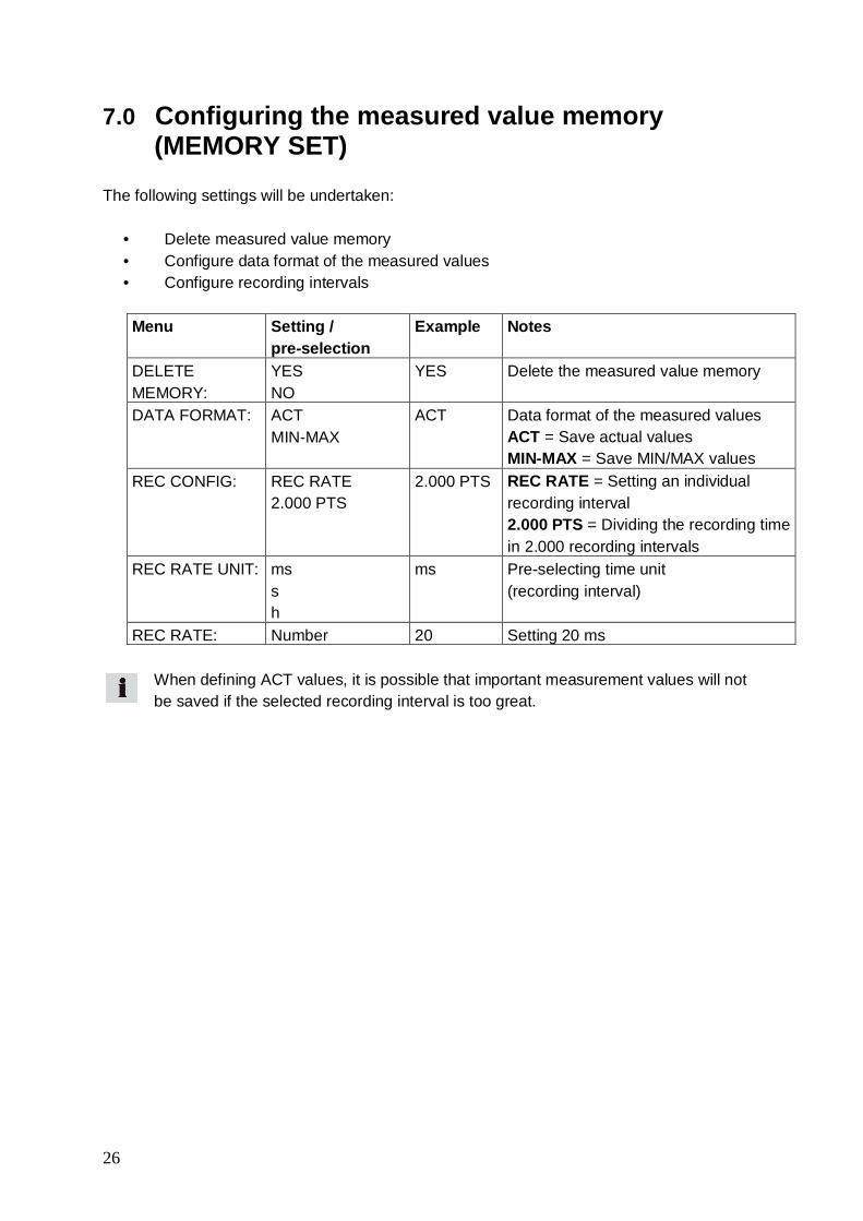
7.0 Configuring the measured value memory(MEMORY SET)
The following settings will be undertaken:
• Delete measured value memory• Configure data format of the measured values• Configure recording intervals
Menu Setting /pre-selection
Example Notes
DELETEMEMORY:
YESNO
YES Delete the measured value memory
DATA FORMAT: ACTMIN-MAX
ACT Data format of the measured valuesACT = Save actual valuesMIN-MAX = Save MIN/MAX values
REC CONFIG: REC RATE2.000 PTS
2.000 PTS REC RATE = Setting an individualrecording interval2.000 PTS = Dividing the recording timein 2.000 recording intervals
REC RATE UNIT: mssh
ms Pre-selecting time unit(recording interval)
REC RATE: Number 20 Setting 20 ms
When defining ACT values, it is possible that important measurement values will notbe saved if the selected recording interval is too great.

27
Example:
No dynamic MIN-MAX values are saved when the recoding interval is set to 200milliseconds. Therefore, the setting MIN-MAX is recommended for dynamic measurements(pressure spikes).
Press and hold (2 seconds)

28
7.1. Deleting the measured value memory (MEM-DELETE MEMORY)
Press once (briefly)
Available for selection:
DELETE MEMORY: YES / NO
The measured value memory will be deleted when the "OK" key is pressed to confirmthe action
7.2. Setting the data format (MEM-DATA FORMAT)
Available selection:
DATA FORMAT: ACTMIN/MAXFAST
When set to FAST, the recording interval for measuring and storing at IN1 is 0.5 ms
7.3. Setting the recording format(MEM-REC-CONFIG)
REC CONFIG
Two different formats can be set:
a. Format 2.000 PTS
The measurement curves are saved with aresolution of 2.000 intervals (points).
b. Format REC RATE
The measurement curves are saved at a resolutiondefined interval.
Example: 20 ms

29
8.0 The REC menu

30
31
9.0 Recording measured values
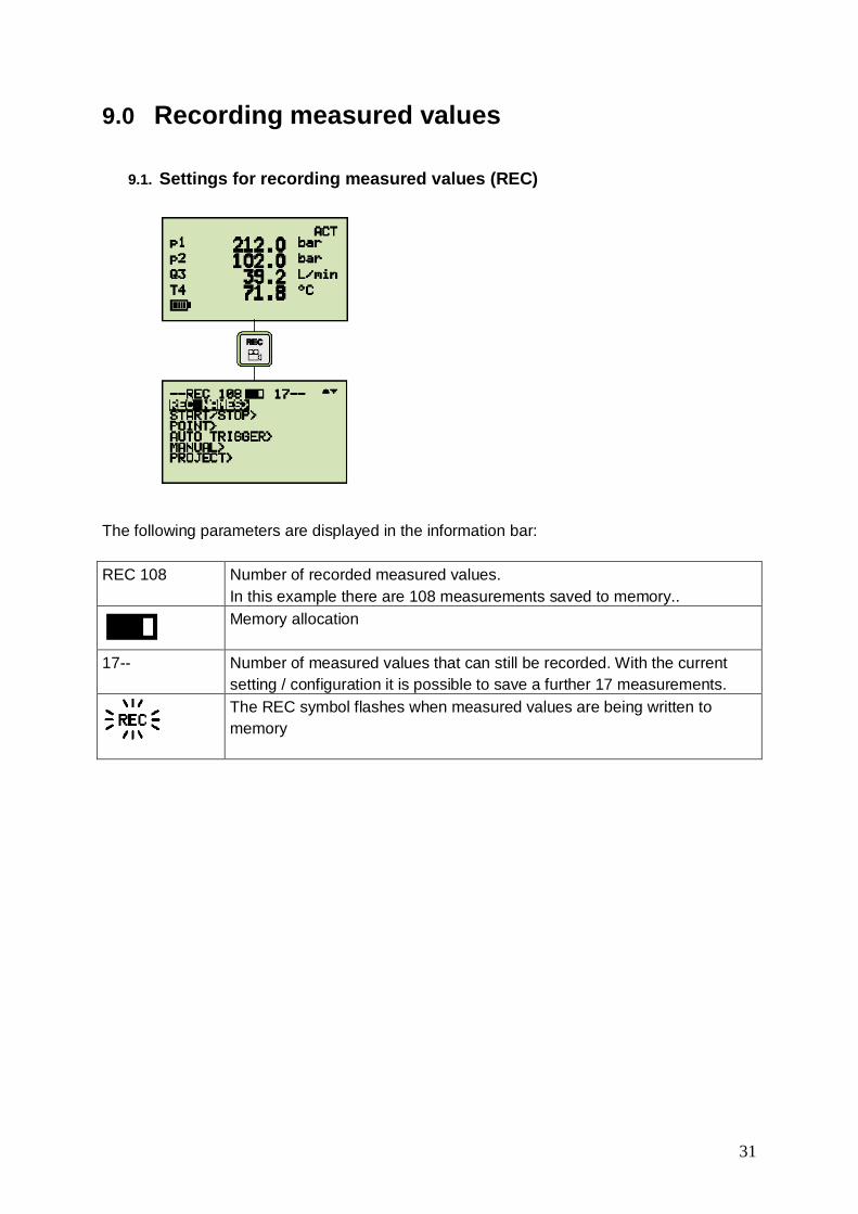
9.1. Settings for recording measured values (REC)
The following parameters are displayed in the information bar:
REC 108 Number of recorded measured values.In this example there are 108 measurements saved to memory..Memory allocation
17-- Number of measured values that can still be recorded. With the currentsetting / configuration it is possible to save a further 17 measurements.The REC symbol flashes when measured values are being written tomemory

32
9.2. The REC NAMES setting
Designations (names) for measurements and channels IN1 / IN2 / IN3 / IN4 are definedthrough the text / numerical input.These settings remain saved in the measuring instrument

33
9.3. Memory function START/STOP
The user controls the recording of measured values using START and STOP / ESC keys.
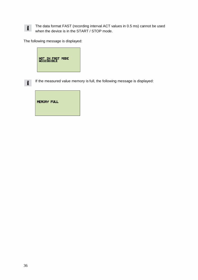
The data format FAST (recording interval ACT values in 0.5 ms) cannot be usedwhen the device is in the START / STOP mode.

34
The following message is displayed:
If the measured value memory is full, the following message is displayed:

35
9.4. Memory function POINT
Measurement points representing a given machine sequence (for example: lifting, sinking,operation under load, off-load operation etc.) are saved in a "point-to-point curve". In theexample shown, the channels p1, p2 and Q4 are connected.Pressing the "OK" key saves the measured values Pressing "STOP/ESC" stops therecording and all measured values are saved in the measured value memory.
Press to save first data recordFor example. p1, p2 and Q4
Press to save second data recordFor example. p1, p2 and Q4
Save arbitrary data record
Pressing stops the recording
All data records will be written in the measuredvalue memory
36
The data format FAST (recording interval ACT values in 0.5 ms) cannot be usedwhen the device is in the START / STOP mode.
The following message is displayed:
If the measured value memory is full, the following message is displayed:
37
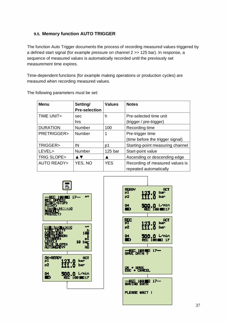
9.5. Memory function AUTO TRIGGER
The function Auto Trigger documents the process of recording measured values triggered bya defined start signal (for example pressure on channel 2 >> 125 bar). In response, asequence of measured values is automatically recorded until the previously setmeasurement time expires.
Time-dependent functions (for example making operations or production cycles) aremeasured when recording measured values.
The following parameters must be set:
Menu Setting/Pre-selection
Values Notes
TIME UNIT> sechrs
h Pre-selected time unit(trigger / pre-trigger)
DURATION Number 100 Recording timePRETRIGGER> Number 1 Pre-trigger time
(time before the trigger signal)TRIGGER> IN p1 Starting-point measuring channelLEVEL> Number 125 bar Start-point valueTRIG SLOPE> ▲▼ ▲ Ascending or descending edgeAUTO READY> YES, NO YES Recording of measured values is
repeated automatically
38
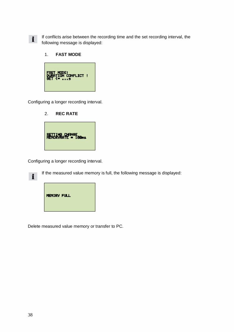
If conflicts arise between the recording time and the set recording interval, thefollowing message is displayed:
1. FAST MODE
Configuring a longer recording interval.
2. REC RATE
Configuring a longer recording interval.
If the measured value memory is full, the following message is displayed:
Delete measured value memory or transfer to PC.

39
9.6. Memory function MANUAL
The manual trigger function documents the process of recording measured values triggeredby a manual start signal initiated by the user. Automatic recording of measured values endsafter predetermined measurement time.
For this reason, time-dependent recordings of measured values are started manually.
The following parameters must be set:
Menu Setting/Pre-selection
Example Notes
TIME UNIT> sechrs
h Pre-selection time unit(trigger / pre-trigger)
DURATION Number 100 Recording timePRETRIGGER> Number 1 Pre-trigger time
(time before the trigger signal)TRIGGER> IN p1 Starting-point measuring
channel

40
If conflicts arise between the recording time and the set recording interval, thefollowing message is displayed:
1. FAST MODE
Configure a longer recording interval.
2. REC RATE
Configure a longer recording interval.
If the measured value memory is full, the following message is displayed:
Delete measured value memory or transfer to PC.

41
9.7. Recording measured values with default PROJECT settings
In this setting, measurements are made using a defined sensor configuration. The user usingthe PC software defines this configuration. This avoids false measurements and wrongsettings.
The preset parameters are altered in the PC software and transferred to the measuringinstrument.
The following parameters can be set:
Menu Setting/Pre-selection
Example Notes
REC NAME> No1 ... 5
Load Test There are max. 5 predefinedsettings (tests) available forselection
INPUT> PILOT PRS Defined sensors are defined foreach channel
WRONGSENSOR!
USE 150 bar Warns of wrong sensor:A pressure sensor with thecorresponding FS (full scale) mustbe connected to this channel
CORRECTSENSOR!
FS 600 l/min Indicates correct sensor.The next channel can beconnected.
When all of the sensors are connected, the respective type of recording (START/STOP,POINT, AUTO TRIGGER, MANUAL) is selected and performed automatically. An internalquery of the connected sensors occurs only before choosing the project setting.

42
10.0 Setting and operating via PC
10.1. Connecting to a PC
Steps:
1 Connect the measuring instrument to the PC via the USB cable2 Launch PC software
Run through the PC software. Once the procedure has been confirmed, the measuringinstrument will be initialized and can communicate with the PC.
10.2. Operating / Configuring via PC
All further steps and settings are described in detail in the PC software:
• Online measurement• Reading out the measured value memory• PROJECT definition• Administering and analyzing measurement curves
ON/OFF
OK
DISP
ESC
REC
LINE
STOP
MEM
ZERO
RESETMIN/MAX
IN1=IN2
SET
11-30VDC I1 I2 I3
I4 PC
PPC-06-plus®
43
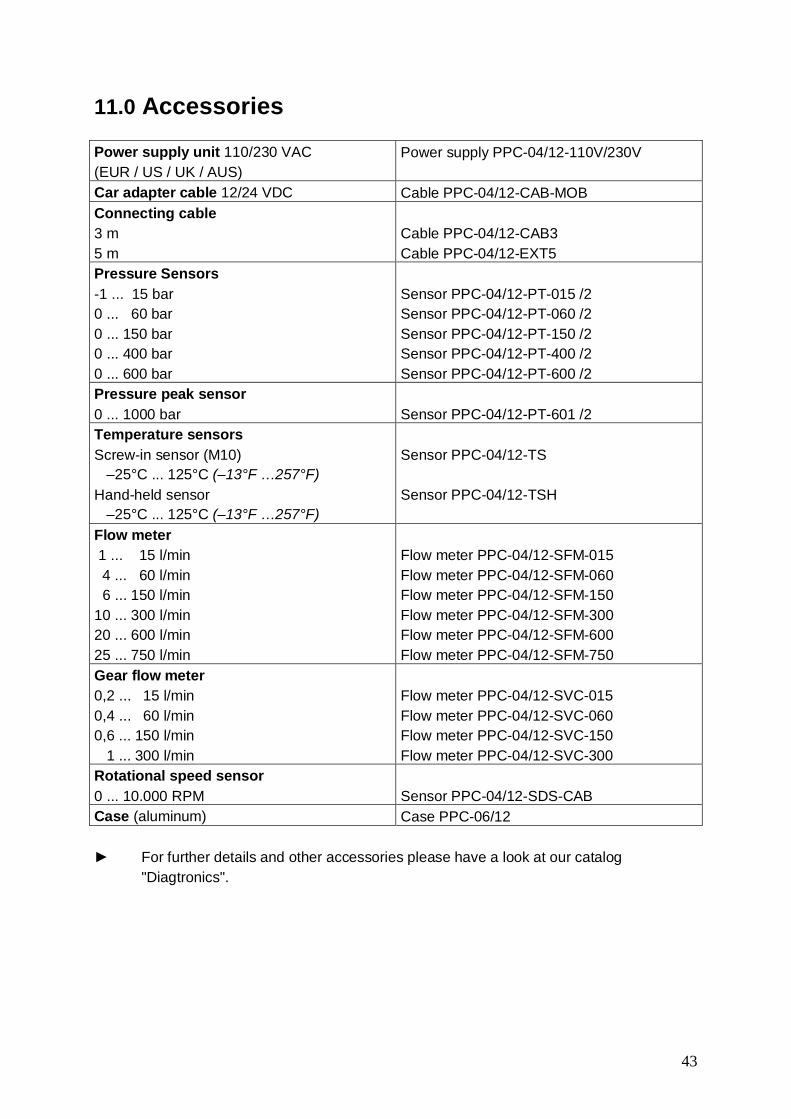
11.0 Accessories
Power supply unit 110/230 VAC(EUR / US / UK / AUS)
Power supply PPC-04/12-110V/230V
Car adapter cable 12/24 VDC Cable PPC-04/12-CAB-MOBConnecting cable3 m5 m
Cable PPC-04/12-CAB3Cable PPC-04/12-EXT5
Pressure Sensors-1 ... 15 bar0 ... 60 bar0 ... 150 bar0 ... 400 bar0 ... 600 bar
Sensor PPC-04/12-PT-015 /2Sensor PPC-04/12-PT-060 /2Sensor PPC-04/12-PT-150 /2Sensor PPC-04/12-PT-400 /2Sensor PPC-04/12-PT-600 /2
Pressure peak sensor0 ... 1000 bar Sensor PPC-04/12-PT-601 /2Temperature sensorsScrew-in sensor (M10) –25°C ... 125°C (–13°F …257°F)Hand-held sensor –25°C ... 125°C (–13°F …257°F)
Sensor PPC-04/12-TS
Sensor PPC-04/12-TSH
Flow meter 1 ... 15 l/min 4 ... 60 l/min 6 ... 150 l/min10 ... 300 l/min20 ... 600 l/min25 ... 750 l/min
Flow meter PPC-04/12-SFM-015Flow meter PPC-04/12-SFM-060Flow meter PPC-04/12-SFM-150Flow meter PPC-04/12-SFM-300Flow meter PPC-04/12-SFM-600Flow meter PPC-04/12-SFM-750
Gear flow meter0,2 ... 15 l/min0,4 ... 60 l/min0,6 ... 150 l/min 1 ... 300 l/min
Flow meter PPC-04/12-SVC-015Flow meter PPC-04/12-SVC-060Flow meter PPC-04/12-SVC-150Flow meter PPC-04/12-SVC-300
Rotational speed sensor0 ... 10.000 RPM Sensor PPC-04/12-SDS-CABCase (aluminum) Case PPC-06/12
► For further details and other accessories please have a look at our catalog "Diagtronics".
44
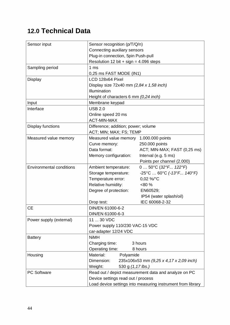
12.0 Technical Data
Sensor input Sensor recognition (p/T/Q/n)Connecting auxiliary sensorsPlug-in connection, 5pin Push-pullResolution 12 bit + sign = 4.096 steps
Sampling period 1 ms0,25 ms FAST MODE (IN1)
Display LCD 128x64 PixelDisplay size 72x40 mm (2,84 x 1,58 inch)IlluminationHeight of characters 6 mm (0,24 inch)
Input Membrane keypadInterface USB 2.0
Online speed 20 msACT-MIN-MAX
Display functions Difference; addition; power; volumeACT; MIN; MAX; FS; TEMP
Measured value memory Measured value memory 1.000.000 pointsCurve memory: 250.000 pointsData format: ACT; MIN-MAX; FAST (0,25 ms)Memory configuration: Interval (e.g. 5 ms) Points per channel (2.000)
Environmental conditions Ambient temperature: 0 … 50°C (32°F... 122°F)Storage temperature: -25°C … 60°C (-13°F... 140°F)Temperature error: 0,02 %/°CRelative humidity: <80 %Degree of protection: EN60529; IP54 (water splash/oil)Drop test: IEC 60068-2-32
CE DIN/EN 61000-6-2DIN/EN 61000-6-3
Power supply (external) 11 ... 30 VDCPower supply 110/230 VAC-15 VDCcar-adapter 12/24 VDC
Battery NiMHCharging time: 3 hoursOperating time: 8 hours
Housing Material: PolyamideDimension: 235x106x53 mm (9,25 x 4,17 x 2,09 inch)Weight: 530 g (1,17 lbs.)
PC Software Read out / depict measurement data and analyze on PCDevice settings read out / processLoad device settings into measuring instrument from library

45
13.0 Description of the memory functions
Configuring the measured value memoryACT During the recording interval (for example, 50 ms), the
current measurement value (ACT) only will be written tothe measured value memory.
DATA FORMAT
MIN-MAX During the recording interval (for example, 50 ms), oneMIN and one MAX value will be written to the measuredvalue memory
2.000 PTS The selected recording time is automatically defined intoa fixed number of recording intervals per channel.Example:Recording time 10 min = 600 sDuration of recording interval = 600 s / 2.000 = 300 ms
REC CONFIG
REC RATE Definition of an individual recording interval(for example. 5 ms)Based in the settings (DATA FORMAT/REC RATE), themeasuring instrument examines if the selected recordingtime must be extended.Example:Recording time 100 h/ conflictRecording time
FAST MODE ACT measured values only are saved at a fixedrecording interval of 0.5 ms via IN1. All other inputs (Inx)are not in function.
Selecting the memory function: sensor PPC-04/12-PT-XXX /2Recording time 60 sMemory function Setting
DATA FORMATSetting REC CONFIG
Curve memory(points)
Number ofmeasuredvalues / pointsp (bar), T (°C)
START / STOP ACTMIN-MAX
- 120.000 p (bar) = 15.000T (°C) = 15.000
2.000 PTS 250.000 p (bar) = 2.000T (°C) = 60
AUTO /MANUALTRIGGER
ACMIN-MAX
REC RATE (5 ms) 250.000 p (bar) = 12.000T (°C) = 60

46
1. Determining the number of the memory functions:Channels Measured
variableNumber ofmeasured
values
Number of recordingintervals
120.000 / measurementvalues = number ofrecording intervals
Example 14 Sensor PPC-04/12-PT °C
barvalues
448 120.000 / 8 = 15.000
Example 22 Sensor PPC-04/12-PT
1 Flow meter PPC-04/12-SFM
1 Sensor PPC-04/12-SDS-CAB
°Cbar
l/min
RPM
values
221
1
6 120.000 / 6 = 20.000
2. Determining the duration of the recording interval:Time Channels Number of
measuredvalues
During of recordinginterval
Example 160s60.000 ms
4 Sensor PPC-04/12-PT 8 60.000 / 15.000 = 4 ms
30s30.000 ms
4 Sensor PPC-04/12-PT 8 40.000 / 15.000 = 2 ms
Example 260s60.000 ms
2 Sensor PPC-04/12-PT1 Flow meter PPC-04/12-SFM1 Sensor PPC-04/12-SDS-CAB
6 60.000 / 20.000 = 3 ms
40s40.000 ms
2 Sensor PPC-04/12-PT1 Flow meter PPC-04/12-SFM1 Sensor PPC-04/12-SDS-CAB
6 40.000 / 20.000 = 2 ms
47
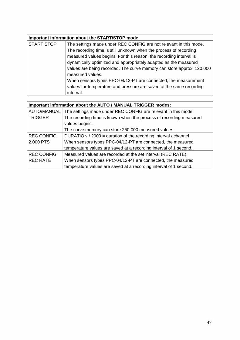
Important information about the START/STOP modeSTART STOP The settings made under REC CONFIG are not relevant in this mode.
The recording time is still unknown when the process of recordingmeasured values begins. For this reason, the recording interval isdynamically optimized and appropriately adapted as the measuredvalues are being recorded. The curve memory can store approx. 120.000measured values.When sensors types PPC-04/12-PT are connected, the measurementvalues for temperature and pressure are saved at the same recordinginterval.
Important information about the AUTO / MANUAL TRIGGER modes:AUTO/MANUALTRIGGER
The settings made under REC CONFIG are relevant in this mode.The recording time is known when the process of recording measuredvalues begins.The curve memory can store 250.000 measured values.
REC CONFIG2.000 PTS
DURATION / 2000 = duration of the recording interval / channelWhen sensors types PPC-04/12-PT are connected, the measuredtemperature values are saved at a recording interval of 1 second.
REC CONFIGREC RATE
Measured values are recorded at the set interval (REC RATE).When sensors types PPC-04/12-PT are connected, the measuredtemperature values are saved at a recording interval of 1 second.

48
1. Determining the duration of the recording interval for REC CONFIG 2000 PTS:Time Channels Meas-
uredvalues
Number ofmeas-
urementvalues
Duration of therecoding interval
60s60.000 ms
4 Sensor PPC-04/12-PT °Cbar
4x604x2.000
60.000 / 2.000 =30 ms
Stored measurement points 8.24030s30.000 ms
4 Sensor PPC-04/12-PT °Cbar
4x304x2.000
30.000 / 2.000 =15 ms
Stored measurement points 8.12060s60.000 ms
2 Sensor PPC-04/12-PT
1 Flow meter PPC-04/12-SFM1 Sensor PPC-04/12-SDS-CAB
°Cbar
l/minRPM
2x602x2.0001x2.0001x2.000
60.000 / 2.000 =30 ms
Stored measurement points 8.12040s40.000 ms
2 Sensor PPC-04/12-PT
1 Flow meter PPC-04/12-SFM1 Sensor PPC-04/12-SDS-CAB
°Cbar
l/minRPM
2x402x2.0001x2.0001x2.000
40.000 / 2.000 =20 ms
Stored measurement points 8.080
2. Determining the number of recording intervals for REC CONFIG/REC RATE 5 ms:Time Channels Meas-
uredvariable
Numberof meas-urementvalues
Number ofrecordingintervals
60s60.000 ms
4 Sensor PPC-04/12-PT °Cbar
4x604x12.000
60.000 / 5 =12.000
Stored measurement points 48.24030s30.000 ms
4 Sensor PPC-04/12-PT °Cbar
4x304x6.000
30.000 / 5 =6.000
Stored measurement points 24.12060s60.000 ms
2 Sensor PPC-04/12-PT
1 Flow meter PPC-04/12-SFM1 Sensor PPC-04/12-SDS-CAB
°Cbar
l/minRPM
2x602x12.0001x12.0001x12.000
60.000 / 5 =12.000
Stored measurement points 48.12040s40.000 ms
2 Sensor PPC-04/12-PT
1 Flow meter PPC-04/12-SFM1 Sensor PPC-04/12-SDS-CAB
°Cbar
l/minRPM
2x402x8.0001x8.0001x8.000
40.000 / 5 =8.000
Stored measurement points 32.080

49
Walter Stauffenberg GmbH & Co. KGPostfach 1745 58777 WerdohlIm Ehrenfeld 4 58791 WerdohlDeutschland
Phone: +49 2392 916-0Fax: +49 2392 2505E-Mail: [email protected]: www.stauff.com S
ubje
ct to
alte
ratio
nTe
chni
sche
Änd
erun
g vo
rbeh
alte
n /