Type C PORCELAIN Cutouts (Standard, Linkbreak, Loadbreak) and … · 2018-03-17 · for use with...
16
January 2014 Phone: 573-682-5521 Email: [email protected] Web: hubbellpowersystems.com Page 1 Catalog 10A January 2014 Type C PORCELAIN Cutouts (Standard, Linkbreak, Loadbreak) and Cutout-Arrester Combinations 10A
Transcript of Type C PORCELAIN Cutouts (Standard, Linkbreak, Loadbreak) and … · 2018-03-17 · for use with...

January 2014
Phone: 573-682-5521 Email: [email protected] Web: hubbellpowersystems.com
Page 1
Catalog 10A January 2014
Type C PORCELAINCutouts (Standard, Linkbreak, Loadbreak)
andCutout-Arrester Combinations
10A

January 2014Page 2
Phone: 573-682-5521 Email: [email protected] Web: hubbellpowersystems.com
Type C Cutouts
LOADBREAK cutout
with Arc-Chute interrupter,
pages 11-13
STANDARD cutout,
pages 3-7
LINKBREAK cutout,
pages 8-10
CUTOUT-ARRESTER
Combinations,
page 14
Application
The primary purpose of any cutout is to provide protection to the lines of your system and the various apparatus on those lines such as transformers and capacitor banks. Chance Type C cutouts provide reliable protection from low-level overloads that just melt the fuse link, intermediate faults, and very high faults, through maximum interrupt capacity.
In addition, Type C cutouts can also be used as a sectionalizing device. With the use of a portable loadbreak tool, Type C cutouts can function much like an overhead disconnect switch. A 300 amp disconnect blade is also available for this purpose.
Ratings/Specifications
STANDARD Type C cutouts have maximum design voltage rat-ings to simplify the confusing ratings of cutouts. There are no restrictions on application to grounded wye, ungrounded wye, or delta systems having maximum operating voltages (line-to-line) equal to or less than the cutout maximum design voltage rating. (See the LINKBREAK and LOADBREAK cutouts for their specifications.) Interruption tests have been performed at full system line-to-line voltage. In each voltage class, there are continuous current ratings of 100 amps, 200 amps and 300 amps. See the table on page 6 for other specifications.

January 2014
Phone: 573-682-5521 Email: [email protected] Web: hubbellpowersystems.com
Page 3
Insulators
The insulators used on Type C cutouts are a sky-glaze gray. The metal to metal leakage distance on the 15 kV cutout insulator is 8.7 inches (220 mm), 12.6 inches (320 mm) on the 27 kV [125 kV LIW (BIL)], 17.3 inches (440 mm) on the 27 kV [150 kV LIW (BIL)], 26 inches (660 mm) on the 36 kV [170 kV LIW (BIL)], and 28.4 inches (720 mm) on the 36 kV [170 kV LIW (BIL)].
Fuseholders
The solid cap on the single vent fuseholder is a copper alloy, silver-plated to provide efficient current transfer. An integral ring is provided in the top tube casting for opening and clos-ing the fuseholder with conventional disconnect tools from the ground, from a bucket truck or from the pole.
The toggle type trunnion casting is a selective silver-plated bronze for efficient current transfer to the lower hinge contacts. A cam shaped projection on each side of the trunnion casting provides high pressure parallel current paths to the lower contacts. These projections, or pivot pins, are cast full round for smooth rotational operation in the hinge. The link ejector assists in arc interruption during low fault current or excessive overload conditions. A groove in the center of the link ejector allows the fuse link’s pigtail to go directly from the fuse tube to the attachment nut. A curved ejector minimizes bending stresses in the pigtail to prevent broken strands. A stainless steel torsion spring on the link ejector helps to rapidly eject the link from the bore of the fuseholder during interruption. The 200 amp link ejector has a wider groove area and increased spring force to accommodate the larger links.
The link ejector is pinned to the trunnion casting with a stainless steel pin to provide resistance to corrosive elements and provide smooth pivotal action. An interlocking feature between the link ejector and tube casting prevents excessive tension on the fuse link during closure, thereby preventing link breakage.
The link ejector employs a hammer effect to enhance toggle action of the trunnion during low fault and overload inter-ruptions, hence dropout action is enhanced. The link ejector provides sufficient surface area to facilitate re-fusing by linemen wearing gloves.
Quality Construction
Efficient Current Transfer
The Chance Type C cutout has an all copper current path. All contacts are silver-plated. Terminals are tin-plated bronze for use with copper or aluminum conductors.
Loadbreak Hooks
Galvanized steel hooks are standard on all Type C cutouts, except the arc chute version, for use with a portable loadbreak tool. These sturdy hooks are mounted on the top support and serve to guide the fuseholder into the latch socket when clos-ing at an off-center angle.
Top Contact
The top contact is attached to the galvanized-steel hood by a stainless rivet to provide a smooth self-aligning action during closing even in severely corrosive environments. The top con-tact provides a socket-type cavity for latching the fuseholder and prevents any possible “over-travel” of the fuseholder. The top contact is made of a highly conductive copper strip with silver-plated embossments to resist corrosion. The contacts are held under constant pressure designed to maintain firm contact with the fuseholder contact surface until fault inter-ruption is accomplished.
Hinge
The hinge on the Type C cutout employs large pivot areas for the fuseholder’s trunnion and is cast of a copper alloy chosen for its strength and corrosion resistance. The hinge contacts are highly conductive copper alloy stampings and are plated to assure low resistance current transfer from the trunnion casting. The parallel current paths are backed up by high strength cantilever springs and are riveted to the hinge cast-ings. Fuseholder can be dropped into place and easily lifted up and out. No tricky maneuvering.
Type C STANDARD Cutout
Chance Type C fuseholders are also mutually interchangeable with the S & C Electric Company’s Type XS cutout.
100 Amp — Single Vent 200 Amp — Single Vent 300 Amp — Disconnect
January 2014Page 4
Phone: 573-682-5521 Email: [email protected] Web: hubbellpowersystems.com
Type C STANDARD Cutout
kVLIW (BIL)
110
125
150
170
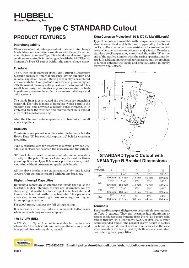
STANDARD Type C Cutout with
NEMA Type B Bracket Dimensions
A16"
406 mm163/8"
416 mm163/8"
416 mm171/4"
438 mm
B51/2"
137 mm71/8"
181 mm71/8"
181 mm81/2"
216 mm
C103/4"
273 mm121/2"
318 mm121/2"
318 mm15"
381 mm
D31/2"
89 mm31/8"
79 mm31/8"
79 mm13/4"
44 mm
E211/2"
559 mm263/4"
679 mm263/4"
679 mm321/2"
826 mm
PRODUCT FEATURES
Interchangeability
Chance was the first to design a cutout that could interchange fuseholders and mounting assemblies with those of another manufacture. Standard Type C fuseholders and mounting as-semblies are mutually interchangeable with the S&C Electric Company’s Type XS cutout (within the same voltage class).
Fusetube
The 1/2-inch inside diameter of the Type C cutout’s 100 ampere fusetube increases internal pressure giving superior and reliable expulsion action. During frequently encountered intermediate fault ranges this diameter also permits higher TRV (transient recovery voltage) values to be tolerated. This small bore design eliminates any concern related to high impedance phase-to-phase faults on ungrounded wye and delta systems.
The inside liner is constructed of a synthetic arc-quenching material. The tube is made of fiberglass which permits the smaller bore and provides a higher burst strength. It is protected from the weather and environment by a special ultra-violet resistant coating.
Also, the Chance fusetube operates with fuselinks from all major suppliers.
Brackets
C cutouts come packed one per carton including a NEMA Heavy Duty “B” bracket with captive 11/2" bolt for crossarm mounting.
Type X brackets, also for crossarm mounting, provides 25/8" additional clearance between the crossarm and the cutout.
“D” brackets are used to mount cutouts and/or arresters directly to the pole. Three brackets may be used for three-phase application. Type D brackets provide a clean, quick mounting without crossarm or special pole bands.
All the above brackets are galvanized steel for long lasting service. Cutouts can be ordered without any brackets.
Higher Interrupt Capacities
By using a copper arc shortening rod inside the top of the fusetube, higher interrupt ratings are obtainable. An arc shortening rod is attached to the cap of some fusetubes and lowers the fuse link within the fusetube. This permits a much shorter arc, resulting in less arc energy, and higher interrupting capacities.
For 200 A tubes, it allows for full voltage rating.
It is necessary to use fuse links with removable buttonheads when arc shortening rods are employed.
170 kV LIW (BIL)
A 170 kV BIL Type C cutout is available for use in areas where the 28.4-inch minimum leakage distance to ground is required. See ordering data, page 6.
Extra Corrosion Protection [150 & 170 kV LIW (BIL) only]
Type C cutouts are available with components of stainless steel inserts, hood and bolts, and copper alloy loadbreak hooks to offer greater corrosion resistance for environmental areas where corrosion can become a major factor. To order a stainless steel/copper alloy cutout add the suffix “S” to the end of the catalog number with the rating specifications de-sired. In additon, an optional spring assist may be provided to further enhance the toggle and drop out action in highly corrosive applications.
Terminals
Tin-plated bronze parallel groove type terminals are standard on Type C cutouts. They can accommodate aluminum or copper conductor sizes ranging from No. 6 (13.3 mm2) solid copper through 4/0 (160.6 mm2) ACSR or 250 (167.5 mm2) kcmil stranded copper. The parallel groove design is perfect for handling two different sizes of conductor as is the case when arresters are being used. Eyebolts are also available. See ordering data, page 10A-6.

January 2014
Phone: 573-682-5521 Email: [email protected] Web: hubbellpowersystems.com
Page 5
STAINLESS-STEEL
SPRING ENSURES
PROPER TOGGLE ACTION
OF FUSELINK EJECTOR
(CAST-BRONZE ON ALL 200
AND LINKBREAK FUSEHOLDERS;
STAINLESS-STEEL ON ALL 100A)
Compare Chance® quality and technical expertise
SILVER-TO-SILVER
CONTACTS
CAST BRONZE HINGE
FOR CORROSION RESISTANCE
COPPER
CURRENT PATH
FUSEHOLDER TOGGLE LATCH
LIMITS TENSION OF FUSELINK
SILVER-TO-SILVER
CONTACTS
WITH STAINLESS STEEL
BACKUP SPRINGS
CAST BRONZE
LOWER TUBE
CASTING
CAST BRONZE TOP TUBE CASTING
AND PULL RING
HIGH-STRENGTH FIBERGLASS FUSETUBE
COATED WITH ULTRA-VIOLET INHIBITOR
GALVANIZED STEEL HOOKS
FOR LOADBREAK TOOL
STAINLESS STEEL
BACKUP SPRING
TO MAINTAIN
CONTACT PRESSURE
BIRD-PROOFED
ONE-PIECE
SOLID-PORCELAIN
INSULATOR
TIN-PLATED BRONZE TERMINALS
FOR USE WITH COPPER
OR ALUMINUM CONDUCTOR
GALVANIZED-STEEL CHANNEL
COPPER
ARC-SHORTENING ROD
(ON SOME RATINGS)
TWO-PLACE LOCKING
TO PREVENT SIDE
MOVEMENT OF HOOD,
CONTACTS OR HOOKS
HOT STICK HOLE IN TRUNNION CASTING
COPPER CURRENT PATH
Type C STANDARD CutoutAll Type C Cutouts meet or exceed ANSI/NEMA specifications.
LARGE NUT TO
FASTEN FUSELINK
WITHOUT BREAK-
ING STRANDS
MECHANICAL ASSIST:
FUSEHOLDER IS AVAIL-
ABLE WITH A TORSIONAL
SPRING ON TRUNNION TO
AID DROP OUT OPERATION
IN CORROSIVE ENVIRON-
MENTS.
SYNTHETIC
FUSE TUBE
LINER

January 2014Page 6
Phone: 573-682-5521 Email: [email protected] Web: hubbellpowersystems.com
No option (may not be used with Z in Option 2)Mechanical Assist Fuse-holder (may not be used with Blank in Option 2)Fargo cutout cover (available for 15 kV only) (may not be used with Blank in Option 2)
*Option Suffix 3Mechanical Assist FuseholderSuffix
3
Blank
M
F
Description
*Adjust total weight when selecting Options below. **Momentary rating — Solid blade ‡Must use removable buttonhead fuse links.
†For application on single-phase to neutral or three-phase solidly-grounded wye-connected circuits where recovery voltage does not exceed the maximum-design voltage of the device.
Type C STANDARD CutoutSpecifications and Ordering Information
*Option Suffix 1Terminal Variations
*Weight
(lb./kg.)
0.33/0.150.16 /0.070.31/0.140.33/0.15
Suffix
1
PEL
R
Description
Parallel-groove clampsSmall eyeboltsLarge eyeboltsLower PG Clamp Rotated 90°
Must specify one selection for Option 1.
See page 10A-15 for Accessories.
*Base
Catalog No.
C710112C710114C710143C710133
Maximum
Design
Voltage
15 kV15 kV15 kV15 kV
Nominal
System Voltage
Thru 14.4 kVThru 14.4 kVThru 14.4 kVThru 14.4 kV
220 mm220 mm220 mm220 mm
Arc
Shorten-
ing Rod
NoYes‡
Yes‡
N/A
Continuous
Current
(Amps)
100100200300
8.7"8.7"8.7"8.7"
Leakage to Ground
Metal to Metal
Interrupt
Capacity
(Asym Amps)
10,000 16,000 12,000
12,000**
15 kV - 110 kV LIW (BIL) — RUS Listed
*Weight
(lb./kg.)
14.23 /6.4514.43 /6.5515.03 /6.8214.53 /6.59
Replacement
Fusetube
Cap
P7001535PE7001767PE7002146PP7001535P
*Option
suffixes
below
1 2 3 1 2 3 1 2 3 1 2 3
320 mm320 mm320 mm320 mm
27 kV - 125 kV LIW (BIL) — RUS Listed27 kV27 kV27 kV27 kV
NoYes‡
Yes‡
N/A
100100200300
8,000 12,000 10,000
12,000**
Thru 24.9 kVThru 24.9 kVThru 24.9 kVThru 24.9 kV
C710211C710213C710242C710233
12.6"12.6"12.6"12.6"
17.73 /8.0417.03 /7.7217.73 /8.0417.23 /7.82
P7001535PE7001768PE7002479PP7001535P
1 2 3 1 2 3 1 2 3 1 2 3
27 kV - 150 kV LIW (BIL) — RUS ListedNo Restrictionsthru 24.9 kV;
†26.4 thru 34.5 kVNo Restrictionsthru 24.9 kV;
†26.4 thru 34.5 kVNo Restrictionsthru 24.9 kV;
†26.4 thru 34.5 kVNo Restrictionsthru 24.9 kV;
†26.4 thru 34.5 kV
440 mm
440 mm
440 mm
440 mm
No
Yes‡
Yes‡
N/A
C710311
C710313
C710342
C710333
27 kV
27 kV
27 kV
27 kV
100
100
200
300
8,000
12,000
10,000
12,000**
17.3"
17.3"
17.3"
17.3"
22.63/10.26
22.83/10.36
23.43/10.63
23.03/10.45
P7001535P
E7001768P
E7002479P
P7001535P
1 2 3
1 2 3
1 2 3
1 2 3
720 mm
720 mm
720 mm
28.4"
28.4"
28.4"
36 kV
27 kV
36 kV
Yes‡
Yes‡
N/A
100
200
300
12,000
12,000
12,000**
36 kV - 170 kV LIW (BIL) — RUS ListedC710713
C710743
C710733
Thru 34.5 kVNo Restrictionsthru 24.9 kV;
†26.4 thru 34.5 kVThru 34.5 kV
E7001743P
E7002117P
P7001535P
30.73/13.94
31.13/14.12
30.73/13.94
NOTE: 26" fuse links are recommended.
1 2 3
1 2 3 1 2 3
660 mm
660 mm
660 mm
26"
26"
26"
36 kV
27 kV
36 kV
Yes‡
Yes‡
N/A
100
200
300
12,000
12,000
12,000**
36 kV - 170 kV LIW (BIL) — RUS ListedC710613
C710643
C710633
Thru 34.5 kVNo Restrictionsthru 24.9 kV;
†26.4 thru 34.5 kVThru 34.5 kV
E7001743P
E7002117P
P7001535P
25.43/11.54
25.83/11.72
25.43/11.54
NOTE: 26" fuse links are recommended.
1 2 3
1 2 3 1 2 3
All Type C Cutouts meet or exceed ANSI/NEMA specifications.
*Option Suffix 2Bracket Variations
*Weight
(lb./kg.)
2.84/1.29
3.75/1.70
7.67/3.48
–––
–––
2.9/1.32
Suffix
2
B
X
D
Z
Blank
V
Description
NEMA Heavy Duty “B” bracket for crossarm (11/2" bolt)Extended type bracket for crossarm (Horizontal section is 25/8" longer than Type B bracket)D-shape bracket (pole)No bracket (must be used with M in Option 3)
No bracket (cannot use with M in Option 3)
Easy-On bracket (Height: 41⁄8" to 55⁄32", Width: 23⁄4" to 4")

January 2014
Phone: 573-682-5521 Email: [email protected] Web: hubbellpowersystems.com
Page 7
Universal Cutout ToolIdeal for Standard and Linkbreak 100 amp fuseholders (ABB, Chance S&C) to easily lift out, place,*open and close. Inverted, secure method also fitsChance Electronic Sectionalizers.Cat. No. PSC4033484 (Wt. 4 oz.) See Tools Catalog Section 2100. *When opening a cutout, follow all work rules and OSHA regula-tions. Not for use with Loadbreak cutouts.
Type C STANDARD CutoutFuseholders and Mounting Assemblies
Ordering Information
15 kV - 110 kV LIW (BIL)
5.85 kg.12.9 lb.
Weight Weight
300A
Blade
100A 200A
Fuseholders27 kV - 17.3" leakage
T7103MMPB
27 kV - 12.6" leakage
T7102MMPB
36 kV - 170 kV LIW (BIL)
T710613TT710643TT710633T
2.8lb.3.2 lb.2.8 lb.
1.27 kg.1.45 kg.1.27 kg.
10.61 kg.23.4 lb.T7106MM
NOTE: 26" fuse links are recommended.
C710613C710643C710633
36 kV - 170 kV LIW (BIL)
T710713TT710743TT710733T
2.8lb.3.2 lb.2.8 lb.
1.27 kg.1.45 kg.1.27 kg.
13.02 kg.28.7 lb.T7107MM
NOTE: 26" fuse links are recommended.
C710713C710743C710733
27 kV - 150 kV LIW (BIL)
9.66 kg.21.3 lb.
C710311C710313C710342C710333
T710311TT710313TT710342TT710333T
2.1 lb.2.3 lb.2.7 lb.2.5 lb.
0.95 kg.1.14 kg.1.22 kg.1.13 kg.
T7103MM
1.8 lb.2.0 lb.2.6 lb.2.1 lb.
*Cutout
Base Catalog
Number
C710112C710114C710143C710133
0.82 kg.0.91 kg.1.18 kg.0.95 kg.
Mounting
Assembly only
*Catalog No.
T7101MM
Fuseholder or
Blade only
Catalog No.
T710112TT710114TT710143TT710133T
7.08 kg.15.6 lb.
27 kV - 125 kV LIW (BIL)
C710211C710213C710242C710233
T710211TT710213TT710242TT710233T
2.1 lb.2.3 lb.2.7 lb.2.5 lb.
0.95 kg.1.14 kg.1.22 kg.1.13 kg.
T7102MM
300A
Blade
100A 200A
Fuseholders
36 kV - 26" leakageT7106MMPB
36 kV - 28.4" leakageT7107MMPB
300A
Blade
200A
Fuseholders
100A
15 kV
8.7" leakage
Catalog No.
T7101MM
Mounting
Assembly
only

January 2014Page 8
Phone: 573-682-5521 Email: [email protected] Web: hubbellpowersystems.com
Type C 100-Amp LINKBREAK Cutout22/36.4 kV - 150 kV LIW (BIL)
22/36.4 kV - 170 kV LIW (BIL)
15 kv - 110 kV LIW (BIL)
15/27 kV - 125 kV LIW (BIL)
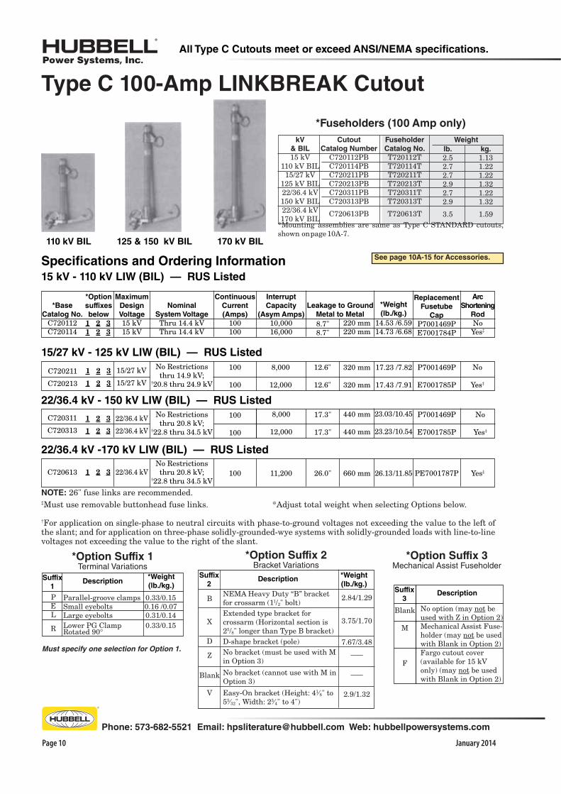
All standard non-loadbreak fuseholders and the linkbreak fuseholders are interchangeable and fit into both the non-loadbreak and Type C LINKBREAK cutout mounting assemblies produced after January 1985. Mounting as-semblies are same as Type C STANDARD cutouts, shown on page 10A-7.
Ratings / Specifications
The 15 kV Type C LINKBREAK cutout has a maximum design voltage rating of 15 kV. There are no voltage restric-tions on application to grounded wye, ungrounded wye, or delta systems having maximum operating voltages (line to line) equal to or less than the cutout maximum design voltage rating.
The 15/27 and 22/36.4 kV Type C LINKBREAK cutouts have maximum design slant voltage ratings. These cutouts are to be used on systems which have phase-to-ground voltages no greater than the value listed to the left of the slant (/) and which have phase-to-phase voltages no greater than the value listed to the right of the slant.
The Type C LINKBREAK cutout is to be used with only Chance, McGraw-Edison and Kearney fuselinks. S&C Electric fuselinks and other fuselinks which require more than 1 inch elongation before breaking must not be used with the Type C LINKBREAK cutout.
A sharp downward pull on the lever with a hookstick breaks the fuselink.
15 kV - 110 kV LIW (BIL) unit
Application
The Chance Type C 100 amp LINKBREAK cutout provides short circuit protection to utility lines with the added feature of mechanical linkbreak capability in a loadbreaking function. Linkbreak cutouts provide reliable protection from overloads that just melt the fuselink through the maximum interrupt capacity of the fuseholder and also provide inductive and capacitive loadbreak capability. For loadbreak ratings see chart, next page.
The unit will also accept the Type C 200 amp non-loadbreak fuseholder or a 300 amp disconnect blade. Each LINK-BREAK cutout includes standard loadbreak hooks to use with portable loadbreak tools. This method is particularly useful for switching of the 200 amp fuseholder and 300 amp disconnect blade.
Design / Product Features
Construction and product details shown on page 10A-3 apply to the LINKBREAK cutout except that the link-ejector on the linkbreak fuseholder is a copper-alloy casting instead of a stainless-steel stamping.
The unit utilizes a stainless-steel linkbreak lever to mechani-cally break fuselink elements thereby obtaining load inter-ruption within the fuseholder. The long lever is positioned directly in-line with the cutout, rather than on one side or in back of the cutout for convenient pull-down operation.
15/27 kV - 125 kV LIW (BIL) unit
January 2014
Phone: 573-682-5521 Email: [email protected] Web: hubbellpowersystems.com
Page 9
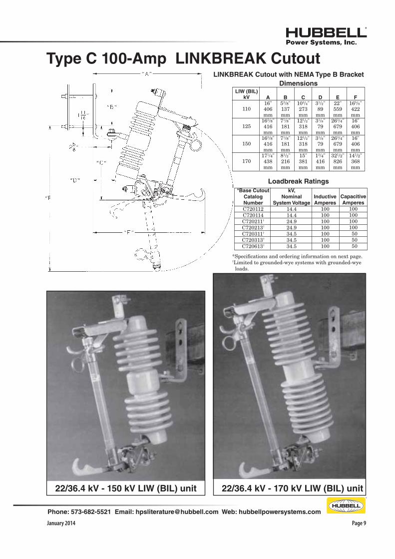
LINKBREAK Cutout with NEMA Type B Bracket
F
165/8"422mm16"406mm16"406mm
141/2"368mm
A
16"406mm
163/8"416mm
163/8"416mm
171/4"438mm
B
53/8"137mm71/8"181mm71/8"181mm81/2"216mm
C
103/4"273mm
121/2"318mm
121/2"318mm15"381mm
D
31/2"89
mm31/8"79
mm31/8"79
mm13/4"416mm
E
22"559mm
263/4"679mm
263/4"679mm
321/2"826mm
LIW (BIL)
kV
110
125
150
170
*Specifications and ordering information on next page.†Limited to grounded-wye systems with grounded-wye loads.
Capacitive
Amperes
100100100100 50 50 50
Inductive
Amperes
100100100100100100100
kV,
Nominal
System Voltage
14.414.424.924.934.534.534.5
*Base Cutout
Catalog
Number
C720112 C720114 C720211†
C720213†
C720311†
C720313†
C720613†
Loadbreak Ratings
Dimensions
22/36.4 kV - 150 kV LIW (BIL) unit 22/36.4 kV - 170 kV LIW (BIL) unit
Type C 100-Amp LINKBREAK Cutout
January 2014Page 10
Phone: 573-682-5521 Email: [email protected] Web: hubbellpowersystems.com
All Type C Cutouts meet or exceed ANSI/NEMA specifications.
26.13 /11.85
‡Must use removable buttonhead fuse links. *Adjust total weight when selecting Options below.
†For application on single-phase to neutral circuits with phase-to-ground voltages not exceeding the value to the left of the slant; and for application on three-phase solidly-grounded-wye systems with solidly-grounded loads with line-to-line voltages not exceeding the value to the right of the slant.
Maximum
Design
Voltage
15 kV15 kV
Nominal
System Voltage
Thru 14.4 kVThru 14.4 kV
220 mm220 mm
*Weight
(lb./kg.)
Arc
Shortening
Rod
NoYes‡
Continuous
Current
(Amps)
100100
8.7"8.7"
Leakage to Ground
Metal to Metal
Interrupt
Capacity
(Asym Amps)
10,000 16,000
14.53 /6.5914.73 /6.68
Specifications and Ordering Information
15 kV - 110 kV LIW (BIL) — RUS Listed
22/36.4 kV
22/36.4 kV
22/36.4 kV - 150 kV LIW (BIL) — RUS Listed
C720311
C720313
No Restrictionsthru 20.8 kV;
†22.8 thru 34.5 kV
660 mm26.0"22/36.4 kV Yes‡11,200
22/36.4 kV -170 kV LIW (BIL) — RUS Listed
C720613No Restrictionsthru 20.8 kV;
†22.8 thru 34.5 kV
lb.
2.52.72.72.92.72.9
3.5
kg.
1.131.221.221.321.221.32
1.59
WeightFuseholder
Catalog No.
T720112TT720114TT720211TT720213TT720311TT720313T
T720613T
Cutout
Catalog Number
C720112PBC720114PBC720211PBC720213PBC720311PBC720313PB
C720613PB
kV
& BIL
15 kV110 kV BIL
15/27 kV125 kV BIL22/36.4 kV150 kV BIL22/36.4 kV 170 kV BIL
*Mounting assemblies are same as Type C STANDARD cutouts, shown on page 10A-7.
Type C 100-Amp LINKBREAK Cutout
110 kV BIL 170 kV BIL125 & 150 kV BIL
*Fuseholders (100 Amp only)
Replacement
Fusetube
Cap
P7001469PE7001784P
No
Yes‡
8,000
12,000
100
100
17.3"
17.3"
440 mm
440 mm
P7001469P
E7001785P
23.03 /10.45
23.23 /10.54
100 PE7001787P
NOTE: 26" fuse links are recommended.
*Base
Catalog No.
C720112C720114
See page 10A-15 for Accessories.
*Option
suffixes
below
1 2 3 1 2 3
C720211
C720213
15/27 kV
15/27 kV
No
Yes‡
8,000
12,000
100
100
15/27 kV - 125 kV LIW (BIL) — RUS Listed
No Restrictionsthru 14.9 kV;
†20.8 thru 24.9 kV
12.6"
12.6"
320 mm
320 mm
P7001469P
E7001785P
17.23 /7.82
17.43 /7.91
1 2 3
1 2 3
1 2 3
1 2 3
1 2 3
No option (may not be used with Z in Option 2)Mechanical Assist Fuse-holder (may not be used with Blank in Option 2)Fargo cutout cover (available for 15 kV only) (may not be used with Blank in Option 2)
*Option Suffix 3Mechanical Assist Fuseholder
Suffix
3
Blank
M
F
Description
*Option Suffix 2Bracket Variations
*Weight
(lb./kg.)
2.84/1.29
3.75/1.70
7.67/3.48
–––
–––
2.9/1.32
Suffix
2
B
X
D
Z
Blank
V
Description
NEMA Heavy Duty “B” bracket for crossarm (11/2" bolt)Extended type bracket for crossarm (Horizontal section is 25/8" longer than Type B bracket)D-shape bracket (pole)No bracket (must be used with M in Option 3)
No bracket (cannot use with M in Option 3)
Easy-On bracket (Height: 41⁄8" to 55⁄32", Width: 23⁄4" to 4")
*Option Suffix 1Terminal Variations
*Weight
(lb./kg.)
0.33/0.150.16 /0.070.31/0.140.33/0.15
Suffix
1
PEL
R
Description
Parallel-groove clampsSmall eyeboltsLarge eyeboltsLower PG Clamp Rotated 90°
Must specify one selection for Option 1.
January 2014
Phone: 573-682-5521 Email: [email protected] Web: hubbellpowersystems.com
Page 11
B
67/8"175 mm
85/8"219 mm
85/8"219 mm
C
103/4"273 mm
121/2"318 mm
121/2"318 mm
A
251/4"642 mm
281/4"719 mm
281/4"719 mm
D
31/2"89 mm
31/8"79 mm
31/8"79 mm
E
255/8"651 mm
307/8"784 mm
307/8"784 mm
kV LIW (BIL)
110
125
150
Dimensions
Application
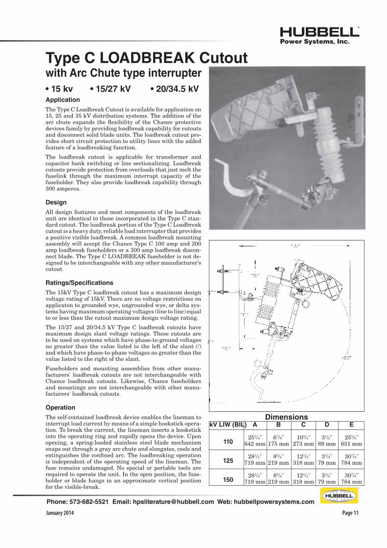
The Type C Loadbreak Cutout is available for application on 15, 25 and 35 kV distribution systems. The addition of the arc chute expands the flexibility of the Chance protective devices family by providing loadbreak capability for cutouts and disconnect solid blade units. The loadbreak cutout pro-vides short circuit protection to utility lines with the added feature of a loadbreaking function.
The loadbreak cutout is applicable for transformer and capacitor bank switching or line sectionalizing. Loadbreak cutouts provide protection from overloads that just melt the fuselink through the maximum interrupt capacity of the fuseholder. They also provide loadbreak capability through 300 amperes.
Design
All design features and most components of the loadbreak unit are identical to those incorporated in the Type C stan-dard cutout. The loadbreak portion of the Type C Loadbreak cutout is a heavy duty, reliable load interrupter that provides a positive visible loadbreak. A common loadbreak mounting assembly will accept the Chance Type C 100 amp and 200 amp loadbreak fuseholders or a 300 amp loadbreak discon-nect blade. The Type C LOADBREAK fuseholder is not de-signed to be interchangeable with any other manufacturer’s cutout.
Ratings/Specifications
The 15kV Type C loadbreak cutout has a maximum design voltage rating of 15kV. There are no voltage restrictions on applicaton to grounded wye, ungrounded wye, or delta sys-tems having maximum operating voltages (line to line) equal to or less than the cutout maximum design voltage rating.
The 15/27 and 20/34.5 kV Type C loadbreak cutouts have maximum design slant voltage ratings. These cutouts are to be used on systems which have phase-to-ground voltages no greater than the value listed to the left of the slant (/) and which have phase-to-phase voltages no greater than the value listed to the right of the slant.
Fuseholders and mounting assemblies from other manu-facturers' loadbreak cutouts are not interchangeable with Chance loadbreak cutouts. Likewise, Chance fuseholders and mountings are not interchangeable with other manu-facturers' loadbreak cutouts.
Operation
The self-contained loadbreak device enables the lineman to interrupt load current by means of a simple hookstick opera-tion. To break the current, the lineman inserts a hookstick into the operating ring and rapidly opens the device. Upon opening, a spring-loaded stainless steel blade mechanism snaps out through a gray arc chute and elongates, cools and extinguishes the confined arc. The loadbreaking operation is independent of the operating speed of the lineman. The fuse remains undamaged. No special or portable tools are required to operate the unit. In the open position, the fuse-holder or blade hangs in an approximate vertical position for the visible-break.
Type C LOADBREAK Cutoutwith Arc Chute type interrupter

January 2014Page 12
Phone: 573-682-5521 Email: [email protected] Web: hubbellpowersystems.com
All Type C Cutouts meet or exceed ANSI/NEMA specifications.
20/34.5 kV
20/34.5 kV
Replacement
Fusetube
Cap
P7001535PE7001767PE7002146PP7001535P
*Base
Catalog No.
C730112C730114C730143C730133
Type C LOADBREAK Cutoutwith Arc Chute Interrruper
15 kV - 110 kV LIW (BIL) — RUS Listed
Nominal
System
Voltage
Thru 14.4 kVThru 14.4 kVThru 14.4 kVThru 14.4 kV
Interrupt
Capacity
(Asym
Amps)
10,00016,00012,000
12,000**
19.33/8.7719.53/8.8620.13/9.1319.63/8.90
Continuous
& Loadbreak
Current
(Amps)
100100200300
*Weight
(lb./kg.)
Arc
Short-
ening
Rod
NoYes‡
Yes‡
N/A
Number
of
Operations
20020020050
Leakage
to Ground,
Metal to Metal
8.7"8.7"8.7"8.7"
220 mm220 mm220 mm220 mm
Maximum
Design
Voltage
15 kV15 kV15 kV15 kV
15/27 kV -125 kV LIW (BIL) — RUS Listed
No Restrictionsthru 14.4 kV;
†20.8 thru 24.9 kV
8,00012,00010,000
12,000**
100100200300
NoYes‡
Yes‡
N/A
20020020050
15/27 kV15/27 kV15/27 kV15/27 kV
C730211C730213C730242C730233
12.6"12.6"12.6"12.6"
320 mm320 mm320 mm320 mm
20/34.5 kV -150 kV LIW (BIL) — RUS Listed
No Restrictionsthru 14.4 kV;
†20.8 thru 34.5 kV
8,000
12,000
100
100No
Yes‡
100
100C730311
C730313
17.3"
17.3"
440 mm
440 mm
**Momentary rating — Solid blade ‡Must use removable buttonhead fuse links. *Adjust total weight when selecting Options below.
†For application on single-phase to neutral circuits with phase-to-ground voltages not exceeding the value to the left of the slant; and for application on three-phase solidly-grounded-wye systems with solidly-grounded loads with line-to-line voltages not exceeding the value to the right of the slant.
20/34.5 kV,
150 kV
LIW (BIL)
15 kV, 110 kV LIW (BIL)15/27 kV,
125 kV
LIW (BIL)
Specifications and Ordering Information
21.93/9.9522.13/10.0422.83/10.3622.33/10.13
P7001535PE7001768PE7002479PP7001535P
27.73/12.58
27.93/12.67
P7001535P
E7001768P
*Option Suffix 3Mechanical Assist FuseholderSuffix
3
Blank
M
Description
No option (may not be used with Z in Option 2)Mechanical AssistFuseholder (may not be used with Blank in Option 2)
See page 10A-15 for Accessories.
*Option
suffixes
below
1 2 3 1 2 3 1 2 3 1 2 3
1 2 3 1 2 3 1 2 3 1 2 3
1 2 3
1 2 3
*Option Suffix 2Bracket Variations
*Weight
(lb./kg.)
2.84/1.29
3.75/1.70
7.67/3.48
–––
–––
2.9/1.32
Suffix
2
B
X
D
Z
Blank
V
Description
NEMA Heavy Duty “B” bracket for crossarm (11/2" bolt)Extended type bracket for crossarm (Horizontal section is 25/8" longer than Type B bracket)D-shape bracket (pole)No bracket (must be used with M in Option 3)
No bracket (cannot use with M in Option 3)
Easy-On bracket (Height: 41⁄8" to 55⁄32", Width: 23⁄4" to 4")
*Option Suffix 1Terminal Variations
*Weight
(lb./kg.)
0.33/0.150.16 /0.070.31/0.140.33/0.15
Suffix
1
PEL
R
Description
Parallel-groove clampsSmall eyeboltsLarge eyeboltsLower PG Clamp Rotated 90°
Must specify one selection for Option 1.
January 2014
Phone: 573-682-5521 Email: [email protected] Web: hubbellpowersystems.com
Page 13
3.3 lb.3.5 lb.4.1 lb.3.6 lb.
Cutout
Catalog
Number
C730112C730114C730143C730133
1.5 kg.1.6 kg.1.9 kg.1.6 kg.
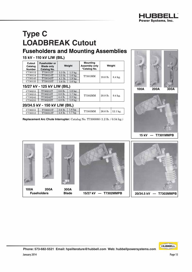
15 kV - 110 kV LIW (BIL)
Mounting
Assembly only
*Catalog No.
T7301MM
Fuseholder or
Blade only
Catalog No.
T730112TT730114TT730143TT730133T
8.4 kg.18.6 lb.
Weight Weight
3.6 lb.3.8 lb.4.4 lb.4.0 lb.
9.4 kg.20.8 lb.T7302MM
1.6 kg.1.7 kg.2.0 kg.1.8 kg.
T730211TT730213TT730242TT730233T
15/27 kV - 125 kV LIW (BIL)
C730211C730213C730242C730233
20/34.5 kV — T7303MMPB
15 kV — T7301MMPB
200A100A 300A
300A
BladeFuseholders
100A 200A
Type C
LOADBREAK CutoutFuseholders and Mounting Assemblies
Replacement Arc Chute Interrupter: Catalog No. T7300080 (1.2 lb. / 0.54 kg.)
15/27 kV — T7302MMPB
20/34.5 kV - 150 kV LIW (BIL)
C730311C730313
T730311TT730313T
3.6 lb.3.8 lb.
1.6 kg.1.7 kg. 12.1 kg.26.6 lb.T7303MM

January 2014Page 14
Phone: 573-682-5521 Email: [email protected] Web: hubbellpowersystems.com
kV LIW (BIL)110125150170
E22" (559 mm)
263/4" (679 mm)263/4" (679 mm)321/2" (826 mm)
G233/4" (603 mm)251/2" (648 mm)251/2" (648 mm)28" (711 mm)
Type C Cutout-Arrester Combinations
15 kV cutout with direct-connected Ohio Brass large-
block, MOV, polymer 9 kV lightning arrester
Advantages of combinationChance cutout-arrester combinations cost less than the total cost of separately purchased components. The combination units install faster, more economically and take up less space in storage, transit and service. Each combined unit takes up a minimum of space on the crossarm and has a favorable weight distribution for minimal off-center loading. The field-proven quality of both cutout and arrester assure consistent
Over-the-Arm Type only
Cutout-Arrester
Dimensions13"
(330 mm)
high performance for the combinations.
These units include Chance cutouts fitted with only Ohio Brass® MOV arresters, superseding previous silicon-carbide units. For easy conversion to the new arrester designation system, refer to the Cutout Cross-Reference Guide, Bul-letin 10-0203.
Ordering Information
To specify a Cutout-Arrester Combination:
1. Select a two-letter designation for the appropriate arrester from the shaded section of the Table at left.
2. Substitute the two letters for the “0” in the Base Catalog No. for the appropriate Cutout listed on page 6, 10 or 12.
Direct
Direct
Direct
Small BlockNormal Duty
5 kA
Large BlockHeavy Duty
10 kA
RiserPole
Oh
io B
rass
9
DL
EL
FL
10
DM
EM
FM
18
DN
EN
FN
27
DP
EP
FP
125 &150
150110
Polymer
Metal Oxide Varister (MOV)Operating
Design
Housing
kV LIW (BIL)
for Cutout
kV Rating
MC
OV
Du
ty C
ycle
kV
Rati
ng
Arr
este
r M
an
ufa
ctu
rer
Arr
este
rC
on
necti
on
Meth
od
January 2014
Phone: 573-682-5521 Email: [email protected] Web: hubbellpowersystems.com
Page 15
Universal Cutout Tool
Ideal for Standard and Linkbreak 100 amp fuse holders (ABB, Chance, S&C) to easily lift out, place, *open and close. Inverted, secure method also fits Chance Electronic Sectionalizers.
Cat. No. PSC4033484 (Wt. 4 oz.) See Tools Catalog Section 2100. *When opening a cutout, follow all work rules and OSHA regula-tions. Not for use with Loadbreak cutouts.
Fastener installation locations (2 fasteners per assembly)
Fargo Cutout Cover
ONE PIECE WILDLIFE PROTECTOR
Available as an Option on Standard and Linkbreak Type C-Porcelain Cutouts (see pages 10A-6 and 10A-10), Cover also may be ordered as a separate line item as Catalog No. CC101. Material: Proprietary low track vinyl that is UV stabilized for long-term performance. Gray color.
-rels, birds or other wildlife.
kV Standard and Linkbreak Cutouts, both Polymer and Porcelain types.
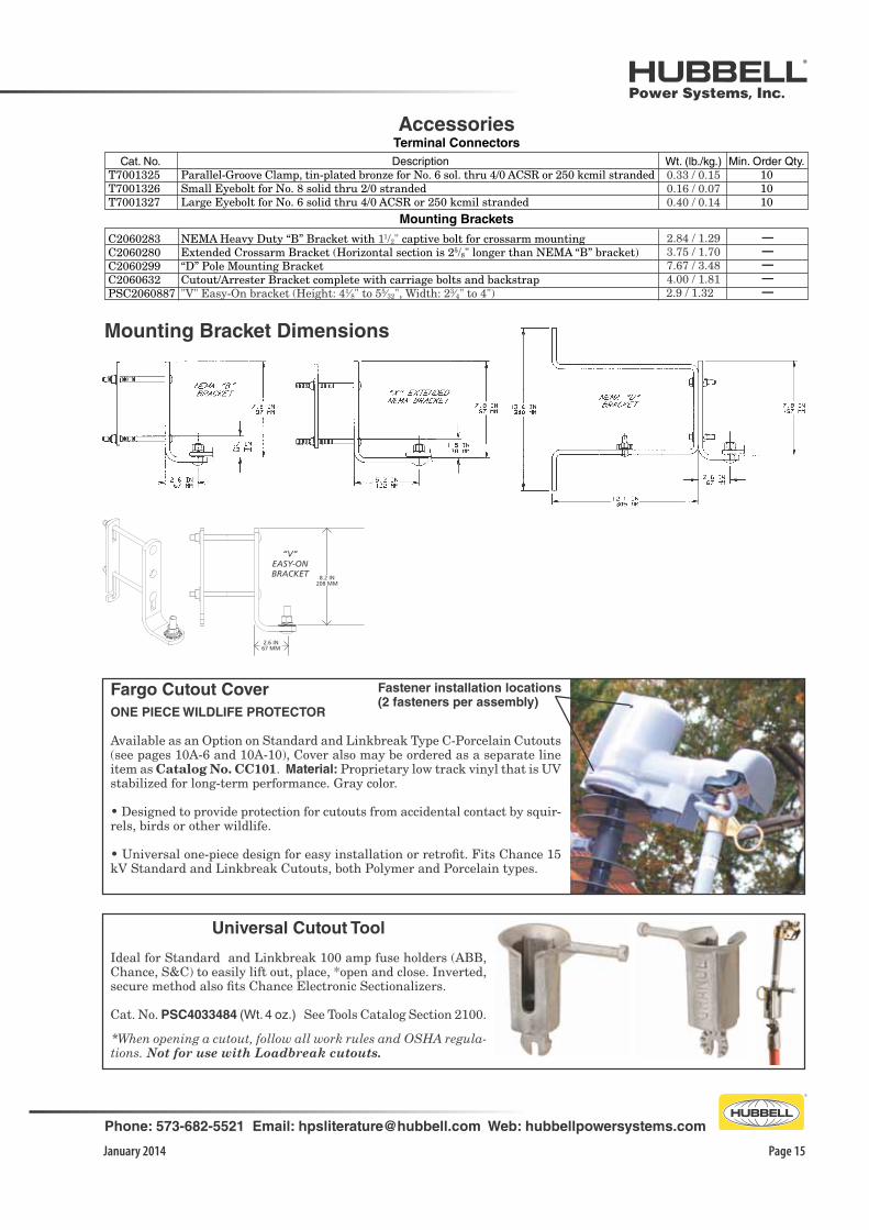
Accessories
Cat. No. T7001325 T7001326 T7001327
Terminal Connectors
Min. Order Qty.101010
DescriptionParallel-Groove Clamp, tin-plated bronze for No. 6 sol. thru 4/0 ACSR or 250 kcmil strandedSmall Eyebolt for No. 8 solid thru 2/0 strandedLarge Eyebolt for No. 6 solid thru 4/0 ACSR or 250 kcmil stranded
Mounting Brackets
Mounting Bracket Dimensions
Wt. (lb./kg.)0.33 / 0.150.16 / 0.070.40 / 0.14
“V”EASY-ONBRACKET
2.6 IN 67 MM
8.2 IN 208 MM
C2060283 C2060280 C2060299 C2060632 PSC2060887
—
—
—
—
—
NEMA Heavy Duty “B” Bracket with 11/2" captive bolt for crossarm mountingExtended Crossarm Bracket (Horizontal section is 25/8" longer than NEMA “B” bracket)“D” Pole Mounting BracketCutout/Arrester Bracket complete with carriage bolts and backstrap"V" Easy-On bracket (Height: 41⁄8" to 55⁄32", Width: 23⁄4" to 4")
2.84 / 1.293.75 / 1.707.67 / 3.484.00 / 1.81
2.9 / 1.32

NEVER COMPROMISE™
www.hubbellpowersystems.com
(205) 699-0840
NOTE: Hubbell has a policy of continuous product improvement. Please visit hubbellpowersystems.com to confirm current design specifications. ©Copyright 2014 Hubbell Incorporated
JANUARY 2014 Catalog 10A
NOTICE: For the latest revision of our Catalog and Literature, click here or visit our web site: www.hubbellpowersystems.com