TYPE 50 PTFE - Designer and manufacturer of Expansion Joints
2
TYPE 50 PTFE WILLBRANDT RUBBER EXPANSION JOINT BG08/2018 – Subject to alterations and misprints Type 50 PTFE is a low-corrugated, PTFE-lined rubber expansion joint. Its low corrugation helps to achieve very low flow resistance. The PTFE lining gives the expansion joint high chemical resistance or an anti-adhe- sive property. The PTFE lining can be used for any rubber compound on Type 50. It is however necessery to ensure that the selected rubber compound achieves the highest possible media resistance, as this is the only way to achieve optimum service life. 25 32 40 50 65 80 100 125 150 200 250 300 350 400 450 500 DN Bellow ØA mm WF* mm 2 130 130 130 130 130 130 130 130 130 130 130 130 200 200 200 200 BL mm 81 81 86 96 111 122 142 168 192 252 302 354 420 480 530 580 1700 1700 1800 3200 5300 8500 12800 18700 25900 41000 59600 82200 117600 154700 204200 227900 Flange PN 10 ØD mm ØC mm 115 140 150 165 185 200 220 250 285 340 395 445 505 565 615 670 65 65 74 86 105 118 137 166 192 252 304 354 412 470 520 570 ØPCD mm 85 100 110 125 145 160 180 210 240 295 350 400 460 515 565 620 Ød mm 14 14 18 18 18 18 18 18 22 22 22 22 22 26 26 26 4 4 4 4 8 8 8 8 8 8 12 12 16 16 20 20 14 15 15 16 16 18 18 18 20 20 20 20 24 25 28 30 s mm n mm Movement absorbtion + mm - mm AX 15 15 15 15 15 15 15 15 15 15 15 15 15 15 15 15 15 15 15 15 15 15 15 15 15 15 15 15 15 15 15 15 LA +/- mm 15 15 15 15 15 15 15 15 15 15 15 15 15 15 15 15 +/- 5,0 15,0 15,0 15,0 15,0 15,0 10,0 10,0 10,0 6,0 6,0 6,0 4,0 4,0 4,0 4,0 Weight mm 1,9 3,1 3,5 3,8 5,4 6,9 8,0 9,7 13,1 16,4 21,7 24,8 38,8 38,6 49,3 57,2 DIMENSIONS FOR DESIGN A 1 / 2 www.belman.com
Transcript of TYPE 50 PTFE - Designer and manufacturer of Expansion Joints

TYPE 50 PTFEWILLBRANDT RUBBER EXPANSION JOINT
BG08/2018 – Subject to alterations and misprints
Type 50 PTFE is a low-corrugated, PTFE-lined rubber expansion joint. Its low corrugation helps to achieve very low flow resistance. The PTFE lining gives the expansion joint high
chemical resistance or an anti-adhe-sive property.The PTFE lining can be used for any rubber compound on Type 50. It is however necessery to ensure that the
selected rubber compound achieves the highest possible media resistance, as this is the only way to achieve optimum service life.
253240506580
100125150200250300350400450500
DN Bellow
ØAmm
WF*mm2
130130130130130130130130130130130130200200200200
BL
mm
81818696
111122142168192252302354420480530580
170017001800320053008500
128001870025900410005960082200
117600154700204200227900
Flange PN 10
ØDmm
ØCmm
115140150165185200220250285340395445505565615670
65657486
105118137166192252304354412470520570
ØPCDmm
85100110125145160180210240295350400460515565620
Ødmm
14141818181818182222222222262626
4444888888
121216162020
14151516161818182020202024252830
smm
nmm
Movement absorbtion
+mm
-mm
AX
15151515151515151515151515151515
15151515151515151515151515151515
LA+/-mm
15151515151515151515151515151515
+/-
5,015,015,015,015,015,010,010,010,06,06,06,04,04,04,04,0
Weight
mm
1,93,13,53,85,46,98,09,7
13,116,421,724,838,838,649,357,2
DIMENSIONS FOR DESIGN A
1 / 2 www.belman.com
BG08/2018 – Subject to alterations and misprints
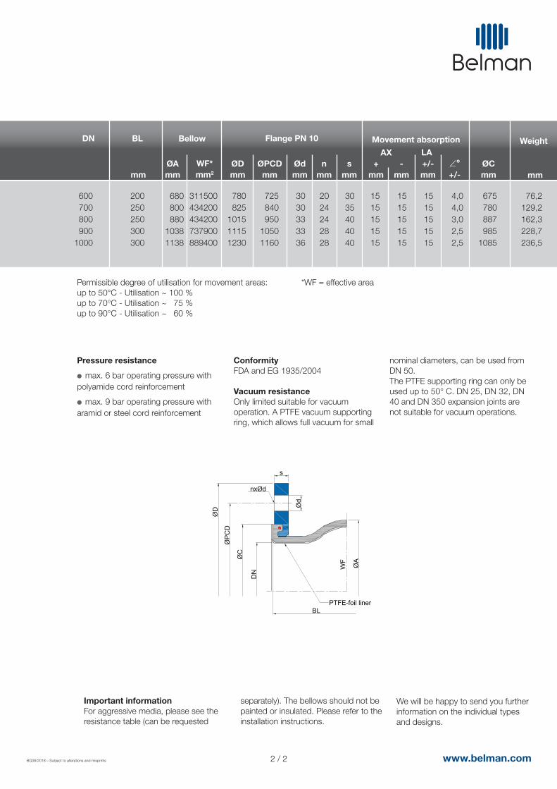
Permissible degree of utilisation for movement areas:up to 50°C - Utilisation ~ 100 %up to 70°C - Utilisation ~ 75 %up to 90°C - Utilisation ~ 60 %
Pressure resistance
l max. 6 bar operating pressure with polyamide cord reinforcement
l max. 9 bar operating pressure with aramid or steel cord reinforcement
ConformityFDA and EG 1935/2004 Vacuum resistanceOnly limited suitable for vacuum operation. A PTFE vacuum supporting ring, which allows full vacuum for small
nominal diameters, can be used from DN 50.The PTFE supporting ring can only be used up to 50° C. DN 25, DN 32, DN 40 and DN 350 expansion joints are not suitable for vacuum operations.
Important informationFor aggressive media, please see the resistance table (can be requested
separately). The bellows should not be painted or insulated. Please refer to the installation instructions.
We will be happy to send you further information on the individual types and designs.
600700800900
1000
DN Bellow
ØAmm
WF*mm2
200250250300300
BL
mm
680800880
10381138
311500434200434200737900889400
Flange PN 10
ØDmm
ØCmm
780825
101511151230
675780887985
1085
ØPCDmm
725840950
10501160
Ødmm
3030333336
2024242828
3035404040
smm
nmm
Movement absorption
+mm
-mm
AX
1515151515
1515151515
LA+/-mm
1515151515
+/-
4,04,03,02,52,5
Weight
mm
76,2129,2162,3228,7236,5
*WF = effective area
2 / 2 www.belman.com