March16 2011 PTFE Catalog - Bay Port Valve PTFE Expansion Joints...type expansion joint,...
20
Transcript of March16 2011 PTFE Catalog - Bay Port Valve PTFE Expansion Joints...type expansion joint,...

Unafl ex® is the industry leader in “combined” technologies for the Expansion Joint and Flexible Hose industries. Since 1972 Unafl ex® has been dedicated to state-of-the-art technologies combined with proven processes.
Our expertise and manufacturing capabilities include a full range of Rubber Expansion Joints, Flue Ducts, Expansion Joint Sound Absorbers, Custom Rubber Hose, Metal Hose, Pump Connectors, and Metal Bellows Type Expansion Joints....now, all available in any combination of PTFE, Metal and Rubber, to suit your application.
This catalog outlines selection and installation of our Metal/Elastomeric/PTFE Bellows type expansion joint, Metal/Elastomeric/PTFE Hose and Pump Connectors for use in pipelines and process vessels to absorb motion and vibration in the system. Our designs incorporate the latest recommendation of the Expansion Joint Manufacturers Association and the Fluid Sealing Association.
Unafl ex® is a full service engineering organization offering a full range of products in the highest grades of elastomers and stainless steel, as well as exotic alloys including Monel®, Inconel®, and Hastelloy®.
Quality control is rigorous and complies with requirements of MIL-1-45208 and MIL-Q-9858. We are ISO 9001:2008 certifi ed and our expansion joints also comply with U.S. Coast Guard requirements. Certifi cation is available.
Special PTFE Products • Large diameter solid PTFE joints similar to styles 112, 113 and 155 available in sizes
to 124’ in diameter. • PTFE lined metal hose–superior strength combined with chemical resistance. • Corrugated PTFE sleeves–built to your specifi cations. • PTFE lined fl ue duct –for superior resistance to corrosive ducting applications. • PTFE tubes–various diameters and lengths, complete fi ttings also available. • PTFE gasket material–precut or roll form.
COMBINEDCOMBINEDIndustry Leader in
Technology
Table of Contents
Unalon Styles 112, 113 and 115 Expansion Joints....................4-7
Installation Instructions for 112, 113 and 115 Series....................8
Unalon 9500 Series Type Expansion Joints................................9-10
Dura-Perm Spool Type Expansion Joints...................................11-13
PTFE/Flexible Rubber Pipe Connectors
and PTFE Lined Serpent Hose....................................................14-15
PTFE Lined Pump Connectors....................................................16
Installation and Maintenance Instructions...............................17
Technical Information............................................................. 18-19
4
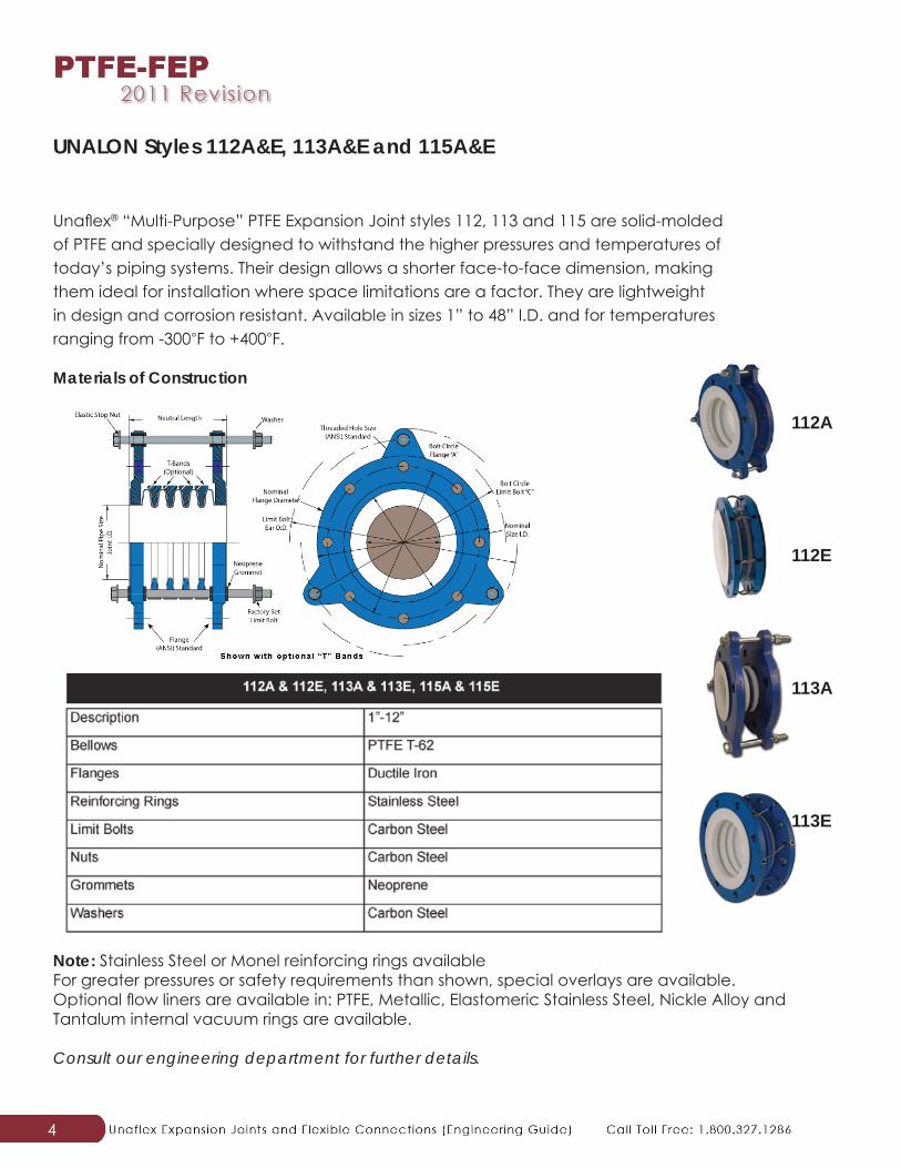
Unafl ex® “Multi-Purpose” PTFE Expansion Joint styles 112, 113 and 115 are solid-molded of PTFE and specially designed to withstand the higher pressures and temperatures of today’s piping systems. Their design allows a shorter face-to-face dimension, making them ideal for installation where space limitations are a factor. They are lightweight in design and corrosion resistant. Available in sizes 1” to 48” I.D. and for temperatures ranging from -300◦F to +400◦F.
Materials of Construction
UNALON Styles 112A&E, 113A&E and 115A&E
Note: Stainless Steel or Monel reinforcing rings availableFor greater pressures or safety requirements than shown, special overlays are available. Optional fl ow liners are available in: PTFE, Metallic, Elastomeric Stainless Steel, Nickle Alloy and Tantalum internal vacuum rings are available.
Consult our engineering department for further details.
112A
112E
113A
113E
5
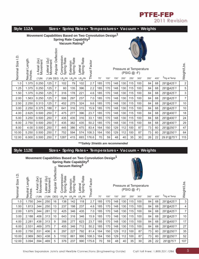
Style 112A Sizes • Spring Rates • Temperatures • Vacuum • Weights
Pressure at Temperature(PSIG @ ◦F)
Movement Capabilities Based on Two Convolution Design1Spring Rate Capability2
Vacuum Rating3
Style 112E Sizes • Spring Rates • Temperatures • Vacuum • Weights
Pressure at Temperature(PSIG @ ◦F)
***Safety Shields are recommended
1.0 1.375 0.250 .125 7 102 79 102 2.7 185 170 148 130 115 100 84 68 29”@425◦F 21.25 1.375 0.250 .125 7 60 135 396 2.2 185 170 148 130 115 100 84 68 29”@425◦F 51.50 1.375 0.250 .125 7 316 178 221 4.6 185 170 148 130 115 100 84 68 29”@425◦F 3
2.00 1.563 0.250 .125 7 506 297 237 7.0 185 170 148 130 115 100 84 68 29”@425◦F 7
2.50 2.250 0.313 .125 7 452 275 324 9.6 185 170 148 130 115 100 84 68 29”@425◦F 103.00 2.250 0.375 .188 7 641 316 315 15.9 185 170 148 130 115 100 84 68 29”@425◦F 10
4.00 2.625 0.500 .250 7 475 277 396 23.7 185 170 148 130 115 100 84 68 29”@400◦F 18
5.00 3.250 0.500 .250 7 435 435 316 33.1 185 170 148 130 115 100 84 68 29”@400◦F 246.00 2.750 0.500 .250 7 435 382 435 50.2 185 170 148 130 115 100 84 68 29”@400◦F 298.00 4.00 0.500 .250 7 445 386 475 83.4 164 150 129 112 100 87 73 60 29”@250◦F 47
10.00 5.250 0.500 .250 7 752 594 574 108.3 164 150 129 112 100 87 73 60 29”@250◦F 6412.00 6.000 0.500 .250 7 1287 415 693 176.6 70 59 48 40 35 30 26 22 29.9”@75◦F 115
Nom
inal
Siz
e I.D
.
Neu
tral L
engt
hIn
ches
.
± A
xial
(Δx)
M
ovem
ent
Late
ral (Δ
y)
Mov
emen
tA
ngul
ar D
efl e
ctio
n
Com
pres
sion
S
prin
g R
ate
Thru
st F
acto
r
(1)IN (1)IN DEG LB2/IN LB2/IN LB2/IN
Ext
ensi
on
Spr
ing
Rat
e
Late
ral
Spr
ing
Rat
e70◦ 100◦ 150◦ 200◦ 250◦ 300◦ 350◦ 400◦ 3Hg at Temp W
eigh
t/Lbs
.
Movement Capabilities Based on Two Convolution Design1Spring Rate Capability2
Vacuum Rating3
1.0 1.750 .344 .250 16 138 142 118 2.7 185 170 148 130 115 100 84 68 29”@425◦F 31.50 1.813 .344 .250 13 237 198 237 4.6 185 170 148 130 115 100 84 68 29”@425◦F 42.00 1.875 .344 .281 12 425 346 435 7.0 185 170 148 130 115 100 84 68 29”@425◦F 7
3.00 2.188 .406 .313 10 643 316 346 15.9 185 170 148 130 115 100 84 68 29”@425◦F 10
4.00 2.281 .438 .313 9 356 277 623 23.7 185 170 148 130 115 100 84 68 29”@400◦F 176.00 2.531 .469 .375 7 455 346 712 50.2 185 170 148 130 115 100 84 68 29”@400◦F 27
8.00 2.750 .531 .406 6 297 227 792 81.4 164 150 129 112 100 87 73 60 29”@250◦F 35
10.00 2.969 .563 .438 5 1152 861 990 108.3 164 150 129 112 100 87 73 60 29”@250◦F 5212.00 3.094 .594 .469 5 376 237 990 175.6 70 59 48 40 35 30 26 22 29”@75◦F 107
Nom
inal
Siz
e I.D
.
Neu
tral L
engt
hIn
ches
.
± A
xial
(Δx)
M
ovem
ent
Late
ral (Δ
y)
Mov
emen
t
Ang
ular
Defl
ect
ion
Com
pres
sion
S
prin
g R
ate
Thru
st F
acto
r
(1)IN (1)IN DEG LB2/IN LB2/IN LB2/IN
Ext
ensi
on
Spr
ing
Rat
e
Late
ral
Spr
ing
Rat
e
70◦ 100◦ 150◦ 200◦ 250◦ 300◦ 350◦ 400◦ 3Hg at Temp Wei
ght/L
bs.
6
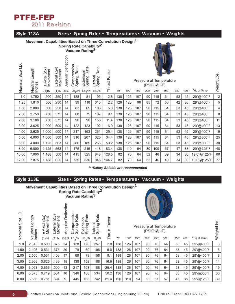
Style 113A Sizes • Spring Rates • Temperatures • Vacuum • Weights
Pressure at Temperature(PSIG @ ◦F)
Style 113E Sizes • Spring Rates • Temperatures • Vacuum • Weights
Pressure at Temperature(PSIG @ ◦F)
***Safety Shields are recommended
Movement Capabilities Based on Three Convolution Design1Spring Rate Capability2
Vacuum Rating3
1.0 1.750 .500 .250 14 188 81 95 2.8 138 126 107 90 115 64 53 45 29”@400◦F 21.25 1.810 .500 .250 14 39 118 310 2.2 128 120 96 85 72 56 42 36 29”@400◦F 51.50 2.000 .500 .250 14 83 65 106 5.0 138 126 107 90 115 64 53 45 29”@400◦F 4
2.00 2.750 .750 .375 14 68 75 107 9.1 138 126 107 90 115 64 53 45 29”@400◦F 8
2.50 3.188 .750 .375 14 90 96 158 11.4 138 126 107 90 115 64 53 45 29”@400◦F 113.00 3.625 1.000 .500 14 122 123 192 16.9 138 126 107 90 115 64 53 45 29”@400◦F 13
4.00 3.625 1.000 .500 14 217 153 261 25.4 138 126 107 90 115 64 53 45 29”@400◦F 19
5.00 4.000 1.000 .500 14 316 207 320 34.4 138 126 107 90 115 64 53 45 29”@300◦F 256.00 4.000 1.125 .563 14 286 185 263 50.2 138 126 107 90 115 64 53 45 29”@300◦F 308.00 6.000 1.125 .563 14 176 215 418 83.4 138 110 94 80 100 57 47 38 29”@125◦F 48
10.00 7.000 1.188 .500 14 415 525 848 128.5 82 70 64 52 46 39 34 30 19.0”@125◦F 6012.00 7.875 1.188 .625 14 735 536 848 144.7 82 70 64 52 46 40 34 30 10.0”@125◦F 77
Nom
inal
Siz
e I.D
.
Neu
tral L
engt
hIn
ches
.
± A
xial
(Δx)
M
ovem
ent
Late
ral (Δ
y)
Mov
emen
tA
ngul
ar D
efl e
ctio
n
Com
pres
sion
S
prin
g R
ate
Thru
st F
acto
r
(1)IN (1)IN DEG LB2/IN LB2/IN LB2/IN
Ext
ensi
on
Spr
ing
Rat
e
Late
ral
Spr
ing
Rat
e
70◦ 100◦ 150◦ 200◦ 250◦ 300◦ 350◦ 400◦ 3Hg at Temp Wei
ght/L
bs.
Movement Capabilities Based on Three Convolution Design1Spring Rate Capability2
Vacuum Rating3
1.0 2.313 0.500 .375 24 128 128 257 2.8 138 126 107 90 76 64 53 45 29”@400◦F 31.50 2.406 0.531 .375 20 79 69 108 5.0 138 126 107 90 76 64 53 45 29”@400◦F 52.00 2.500 0.531 .406 17 69 79 158 9.1 138 126 107 90 76 64 53 45 29”@400◦F 8
3.00 2.906 0.625 .469 15 138 158 188 16.9 138 126 107 90 76 64 53 45 29”@400◦F 14
4.00 3.063 0.656 .500 13 217 158 188 25.4 138 126 107 90 76 64 53 45 29”@400◦F 196.00 3.375 0.719 .531 10 346 188 534 50.2 138 126 107 90 76 64 53 45 29”@300◦F 30
8.00 3.656 0.781 .594 9 445 168 742 81.4 120 110 94 80 67 57 47 38 29”@125◦F 39
Nom
inal
Siz
e I.D
.
Neu
tral L
engt
hIn
ches
.
± A
xial
(Δx)
M
ovem
ent
Late
ral (Δ
y)
Mov
emen
t
Ang
ular
Defl
ect
ion
Com
pres
sion
S
prin
g R
ate
Thru
st F
acto
r
(1)IN (1)IN DEG LB2/IN LB2/IN LB2/IN
Ext
ensi
on
Spr
ing
Rat
e
Late
ral
Spr
ing
Rat
e
70◦ 100◦ 150◦ 200◦ 250◦ 300◦ 350◦ 400◦ 3Hg at Temp Wei
ght/L
bs.
7
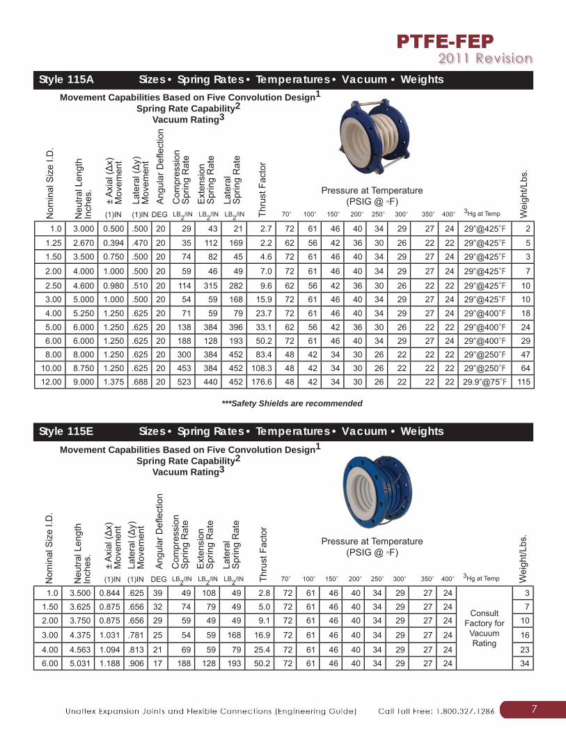
Style 115A Sizes • Spring Rates • Temperatures • Vacuum • Weights
Pressure at Temperature(PSIG @ ◦F)
Style 115E Sizes • Spring Rates • Temperatures • Vacuum • Weights
Pressure at Temperature(PSIG @ ◦F)
***Safety Shields are recommended
1.0 3.000 0.500 .500 20 29 43 21 2.7 72 61 46 40 34 29 27 24 29”@425◦F 2
1.25 2.670 0.394 .470 20 35 112 169 2.2 62 56 42 36 30 26 22 22 29”@425◦F 51.50 3.500 0.750 .500 20 74 82 45 4.6 72 61 46 40 34 29 27 24 29”@425◦F 3
2.00 4.000 1.000 .500 20 59 46 49 7.0 72 61 46 40 34 29 27 24 29”@425◦F 7
2.50 4.600 0.980 .510 20 114 315 282 9.6 62 56 42 36 30 26 22 22 29”@425◦F 103.00 5.000 1.000 .500 20 54 59 168 15.9 72 61 46 40 34 29 27 24 29”@425◦F 10
4.00 5.250 1.250 .625 20 71 59 79 23.7 72 61 46 40 34 29 27 24 29”@400◦F 18
5.00 6.000 1.250 .625 20 138 384 396 33.1 62 56 42 36 30 26 22 22 29”@400◦F 246.00 6.000 1.250 .625 20 188 128 193 50.2 72 61 46 40 34 29 27 24 29”@400◦F 298.00 8.000 1.250 .625 20 300 384 452 83.4 48 42 34 30 26 22 22 22 29”@250◦F 47
10.00 8.750 1.250 .625 20 453 384 452 108.3 48 42 34 30 26 22 22 22 29”@250◦F 6412.00 9.000 1.375 .688 20 523 440 452 176.6 48 42 34 30 26 22 22 22 29.9”@75◦F 115
Nom
inal
Siz
e I.D
.
Neu
tral L
engt
hIn
ches
.
± A
xial
(Δx)
M
ovem
ent
Late
ral (Δ
y)
Mov
emen
tA
ngul
ar D
efl e
ctio
n
Com
pres
sion
S
prin
g R
ate
Thru
st F
acto
r
(1)IN (1)IN DEG LB2/IN LB2/IN LB2/IN
Ext
ensi
on
Spr
ing
Rat
e
Late
ral
Spr
ing
Rat
e
70◦ 100◦ 150◦ 200◦ 250◦ 300◦ 350◦ 400◦ 3Hg at Temp Wei
ght/L
bs.
Movement Capabilities Based on Five Convolution Design1Spring Rate Capability2
Vacuum Rating3
Movement Capabilities Based on Five Convolution Design1Spring Rate Capability2
Vacuum Rating3
1.0 3.500 0.844 .625 39 49 108 49 2.8 72 61 46 40 34 29 27 24
ConsultFactory for
VacuumRating
31.50 3.625 0.875 .656 32 74 79 49 5.0 72 61 46 40 34 29 27 24 72.00 3.750 0.875 .656 29 59 49 49 9.1 72 61 46 40 34 29 27 24 10
3.00 4.375 1.031 .781 25 54 59 168 16.9 72 61 46 40 34 29 27 24 16
4.00 4.563 1.094 .813 21 69 59 79 25.4 72 61 46 40 34 29 27 24 236.00 5.031 1.188 .906 17 188 128 193 50.2 72 61 46 40 34 29 27 24 34
Nom
inal
Siz
e I.D
.
Neu
tral L
engt
hIn
ches
.
± A
xial
(Δx)
M
ovem
ent
Late
ral (Δ
y)
Mov
emen
t
Ang
ular
Defl
ect
ion
Com
pres
sion
S
prin
g R
ate
Thru
st F
acto
r
(1)IN (1)IN DEG LB2/IN LB2/IN LB2/IN
Ext
ensi
on
Spr
ing
Rat
e
Late
ral
Spr
ing
Rat
e
70◦ 100◦ 150◦ 200◦ 250◦ 300◦ 350◦ 400◦ 3Hg at Temp Wei
ght/L
bs.
8
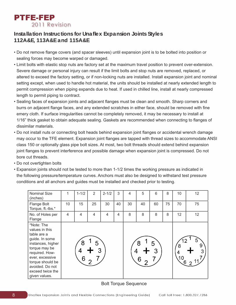
Installation Instructions for Unafl ex Expansion Joints Styles 112A&E, 113A&E and 115A&E
• Do not remove fl ange covers (and spacer sleeves) until expansion joint is to be bolted into position or sealing forces may become warped or damaged.
• Limit bolts with elastic stop nuts are factory set at the maximum travel position to prevent over-extension. Severe damage or personal injury can result if the limit bolts and stop nuts are removed, replaced, or altered to exceed the factory setting, or if non-locking nuts are installed. Install expansion joint and nominal setting except, when used to handle hot material, the units should be installed at nearly extended length to permit compression when piping expands due to heat. If used in chilled line, install at nearly compressed length to permit piping to contract.
• Sealing faces of expansion joints and adjacent fl anges must be clean and smooth. Sharp corners and burrs on adjacent fl ange faces, and any extended scratches in either face, should be removed with fi ne emery cloth. If surface irregularities cannot be completely removed, it may be necessary to install at 1/16” thick gasket to obtain adequate sealing. Gaskets are recommended when connecting to fl anges of dissimilar materials.
• Do not install nuts or connecting bolt heads behind expansion joint fl anges or accidental wrench damage may occur to the TFE element. Expansion joint fl anges are tapped with thread sizes to accommodate ANSI class 150 or optionally glass pipe bolt sizes. At most, two bolt threads should extend behind expansion joint fl anges to prevent interference and possible damage when expansion joint is compressed. Do not bore cut threads.
• Do not overtighten bolts• Expansion joints should not be tested to more than 1-1/2 times the working pressure as indicated in
the following pressure/temperature curves. Anchors must also be designed to withstand test pressure conditions and all anchors and guides must be installed and checked prior to testing.
Nominal Size (inches)
1 1-1/2 2 2-1/2 3 4 5 6 8 10 12
Flange Bolt Torque, ft.-lbs.*
10 15 25 30 40 30 40 60 75 70 75
No. of Holes per Flange
4 4 4 4 4 8 8 8 8 12 12
*Note: The values in this table are a guide. In some instances, higher torque may be required. How-ever, excessive torque should be avoided. Do not exceed twice the given values.
Bolt Torque Sequence
9
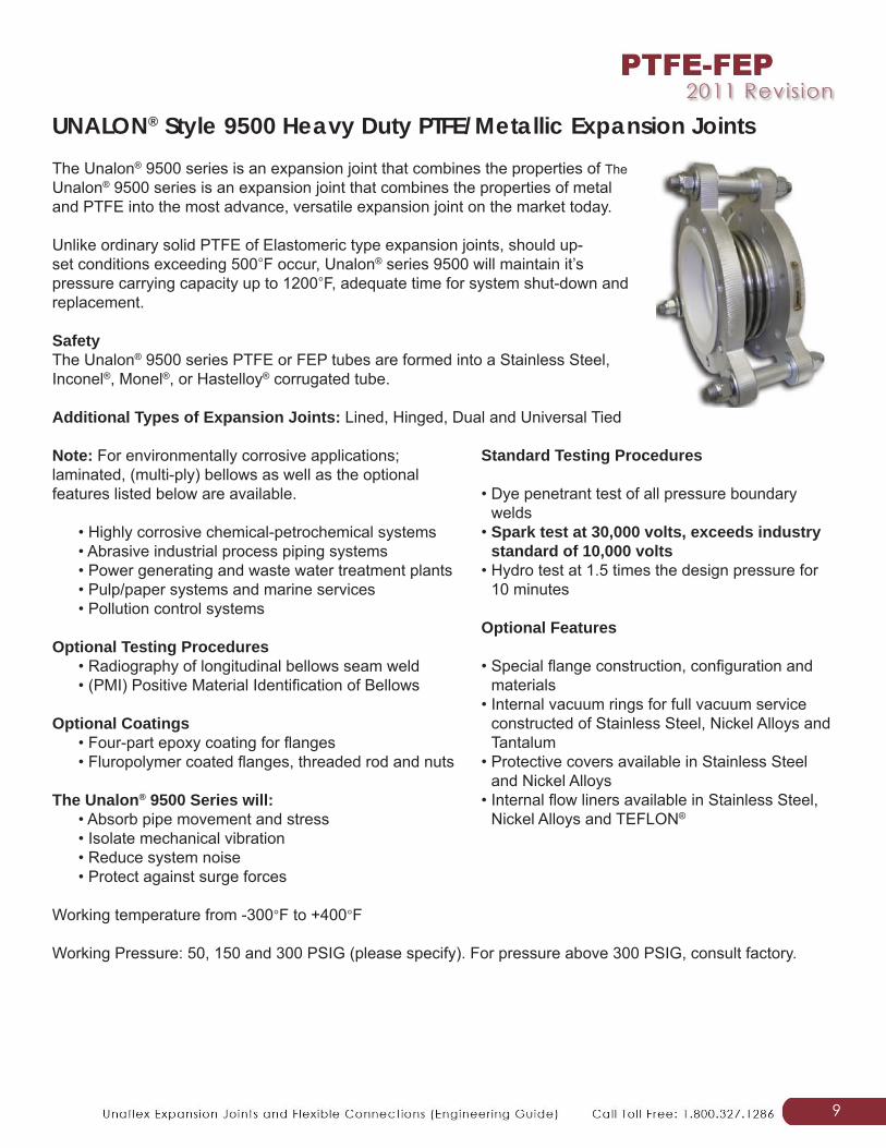
UNALON® Style 9500 Heavy Duty PTFE/Metallic Expansion JointsThe Unalon® 9500 series is an expansion joint that combines the properties of The Unalon® 9500 series is an expansion joint that combines the properties of metal and PTFE into the most advance, versatile expansion joint on the market today.
Unlike ordinary solid PTFE of Elastomeric type expansion joints, should up-set conditions exceeding 500◦F occur, Unalon® series 9500 will maintain it’s pressure carrying capacity up to 1200◦F, adequate time for system shut-down and replacement.
Safety The Unalon® 9500 series PTFE or FEP tubes are formed into a Stainless Steel, Inconel®, Monel®, or Hastelloy® corrugated tube.
Additional Types of Expansion Joints: Lined, Hinged, Dual and Universal Tied
Note: For environmentally corrosive applications; laminated, (multi-ply) bellows as well as the optional features listed below are available.
• Highly corrosive chemical-petrochemical systems • Abrasive industrial process piping systems • Power generating and waste water treatment plants • Pulp/paper systems and marine services • Pollution control systems
Optional Testing Procedures • Radiography of longitudinal bellows seam weld • (PMI) Positive Material Identifi cation of Bellows
Optional Coatings • Four-part epoxy coating for fl anges • Fluropolymer coated fl anges, threaded rod and nuts
The Unalon® 9500 Series will: • Absorb pipe movement and stress • Isolate mechanical vibration • Reduce system noise • Protect against surge forces
Working temperature from -300◦F to +400◦F
Working Pressure: 50, 150 and 300 PSIG (please specify). For pressure above 300 PSIG, consult factory.
Standard Testing Procedures
• Dye penetrant test of all pressure boundary welds
• Spark test at 30,000 volts, exceeds industry standard of 10,000 volts
• Hydro test at 1.5 times the design pressure for 10 minutes
Optional Features
• Special fl ange construction, confi guration and materials
• Internal vacuum rings for full vacuum service constructed of Stainless Steel, Nickel Alloys and Tantalum
• Protective covers available in Stainless Steel and Nickel Alloys
• Internal fl ow liners available in Stainless Steel, Nickel Alloys and TEFLON®
10
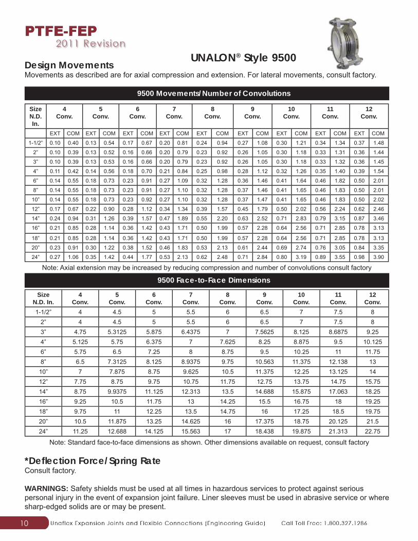
Design MovementsMovements as described are for axial compression and extension. For lateral movements, consult factory.
*Defl ection Force/Spring RateConsult factory.
WARNINGS: Safety shields must be used at all times in hazardous services to protect against serious personal injury in the event of expansion joint failure. Liner sleeves must be used in abrasive service or where sharp-edged solids are or may be present.
Size N.D. In.
4Conv.
5Conv.
6Conv.
7Conv.
8Conv.
9Conv.
10Conv.
11Conv.
12Conv.
EXT COM EXT COM EXT COM EXT COM EXT COM EXT COM EXT COM EXT COM EXT COM
1-1/2” 0.10 0.40 0.13 0.54 0.17 0.67 0.20 0.81 0.24 0.94 0.27 1.08 0.30 1.21 0.34 1.34 0.37 1.48
2” 0.10 0.39 0.13 0.52 0.16 0.66 0.20 0.79 0.23 0.92 0.26 1.05 0.30 1.18 0.33 1.31 0.36 1.44
3” 0.10 0.39 0.13 0.53 0.16 0.66 0.20 0.79 0.23 0.92 0.26 1.05 0.30 1.18 0.33 1.32 0.36 1.45
4” 0.11 0.42 0.14 0.56 0.18 0.70 0.21 0.84 0.25 0.98 0.28 1.12 0.32 1.26 0.35 1.40 0.39 1.54
6” 0.14 0.55 0.18 0.73 0.23 0.91 0.27 1.09 0.32 1.28 0.36 1.46 0.41 1.64 0.46 1.82 0.50 2.01
8” 0.14 0.55 0.18 0.73 0.23 0.91 0.27 1.10 0.32 1.28 0.37 1.46 0.41 1.65 0.46 1.83 0.50 2.01
10” 0.14 0.55 0.18 0.73 0.23 0.92 0.27 1.10 0.32 1.28 0.37 1.47 0.41 1.65 0.46 1.83 0.50 2.02
12” 0.17 0.67 0.22 0.90 0.28 1.12 0.34 1.34 0.39 1.57 0.45 1.79 0.50 2.02 0.56 2.24 0.62 2.46
14” 0.24 0.94 0.31 1.26 0.39 1.57 0.47 1.89 0.55 2.20 0.63 2.52 0.71 2.83 0.79 3.15 0.87 3.46
16” 0.21 0.85 0.28 1.14 0.36 1.42 0.43 1.71 0.50 1.99 0.57 2.28 0.64 2.56 0.71 2.85 0.78 3.13
18” 0.21 0.85 0.28 1.14 0.36 1.42 0.43 1.71 0.50 1.99 0.57 2.28 0.64 2.56 0.71 2.85 0.78 3.13
20” 0.23 0.91 0.30 1.22 0.38 1.52 0.46 1.83 0.53 2.13 0.61 2.44 0.69 2.74 0.76 3.05 0.84 3.35
24” 0.27 1.06 0.35 1.42 0.44 1.77 0.53 2.13 0.62 2.48 0.71 2.84 0.80 3.19 0.89 3.55 0.98 3.90
9500 Movements/Number of Convolutions
Note: Axial extension may be increased by reducing compression and number of convolutions consult factory
Size N.D. In.
4Conv.
5Conv.
6Conv.
7Conv.
8Conv.
9Conv.
10Conv.
11Conv.
12Conv.
1-1/2” 4 4.5 5 5.5 6 6.5 7 7.5 82” 4 4.5 5 5.5 6 6.5 7 7.5 83” 4.75 5.3125 5.875 6.4375 7 7.5625 8.125 8.6875 9.254” 5.125 5.75 6.375 7 7.625 8.25 8.875 9.5 10.1256” 5.75 6.5 7.25 8 8.75 9.5 10.25 11 11.758” 6.5 7.3125 8.125 8.9375 9.75 10.563 11.375 12.138 13
10” 7 7.875 8.75 9.625 10.5 11.375 12.25 13.125 1412” 7.75 8.75 9.75 10.75 11.75 12.75 13.75 14.75 15.7514” 8.75 9.9375 11.125 12.313 13.5 14.688 15.875 17.063 18.2516” 9.25 10.5 11.75 13 14.25 15.5 16.75 18 19.2518” 9.75 11 12.25 13.5 14.75 16 17.25 18.5 19.7520” 10.5 11.875 13.25 14.625 16 17.375 18.75 20.125 21.524” 11.25 12.688 14.125 15.563 17 18.438 19.875 21.313 22.75
9500 Face-to-Face Dimensions
Note: Standard face-to-face dimensions as shown. Other dimensions available on request, consult factory
UNALON® Style 9500
11
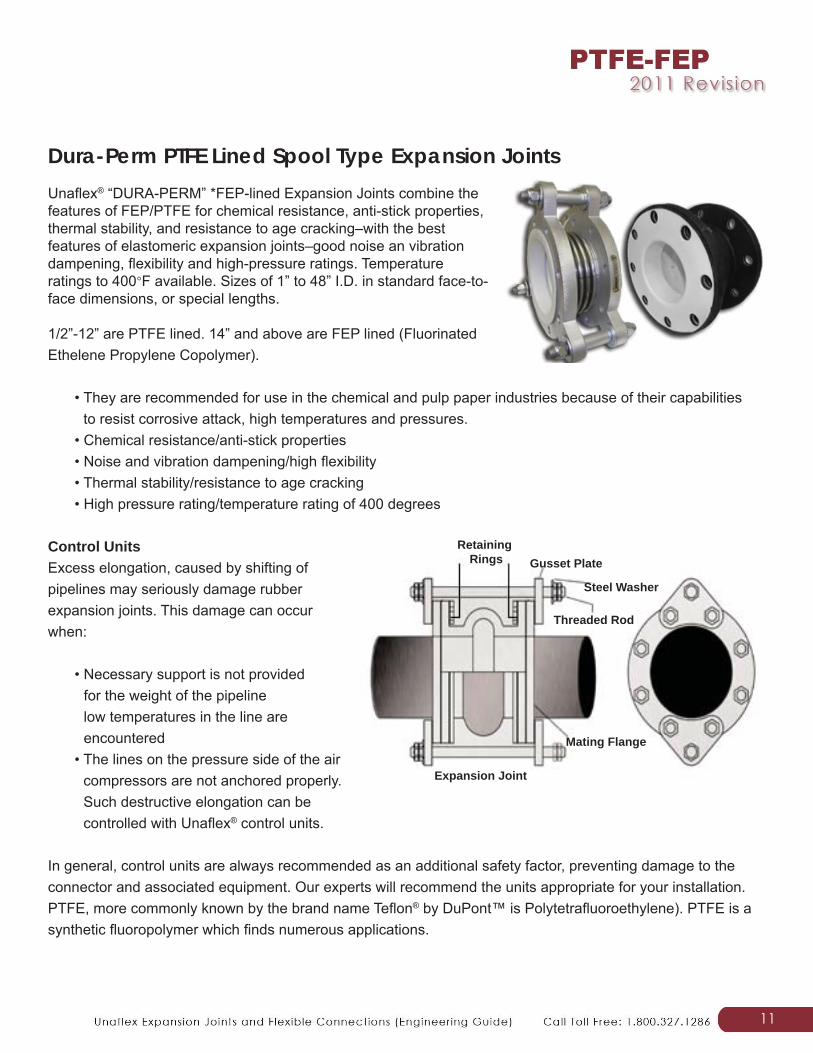
Dura-Perm PTFE Lined Spool Type Expansion JointsUnafl ex® “DURA-PERM” *FEP-lined Expansion Joints combine the features of FEP/PTFE for chemical resistance, anti-stick properties, thermal stability, and resistance to age cracking–with the best features of elastomeric expansion joints–good noise an vibration dampening, fl exibility and high-pressure ratings. Temperature ratings to 400◦F available. Sizes of 1” to 48” I.D. in standard face-to-face dimensions, or special lengths.
1/2”-12” are PTFE lined. 14” and above are FEP lined (Fluorinated Ethelene Propylene Copolymer).
• They are recommended for use in the chemical and pulp paper industries because of their capabilities to resist corrosive attack, high temperatures and pressures.
• Chemical resistance/anti-stick properties • Noise and vibration dampening/high fl exibility • Thermal stability/resistance to age cracking • High pressure rating/temperature rating of 400 degrees
Control UnitsExcess elongation, caused by shifting of pipelines may seriously damage rubber expansion joints. This damage can occur when:
• Necessary support is not provided for the weight of the pipeline low temperatures in the line are encountered
• The lines on the pressure side of the air compressors are not anchored properly. Such destructive elongation can be controlled with Unafl ex® control units.
In general, control units are always recommended as an additional safety factor, preventing damage to the connector and associated equipment. Our experts will recommend the units appropriate for your installation. PTFE, more commonly known by the brand name Tefl on® by DuPont™ is Polytetrafl uoroethylene). PTFE is a synthetic fl uoropolymer which fi nds numerous applications.
Retaining Rings Gusset Plate
Steel Washer
Mating Flange
Threaded Rod
Expansion Joint
12
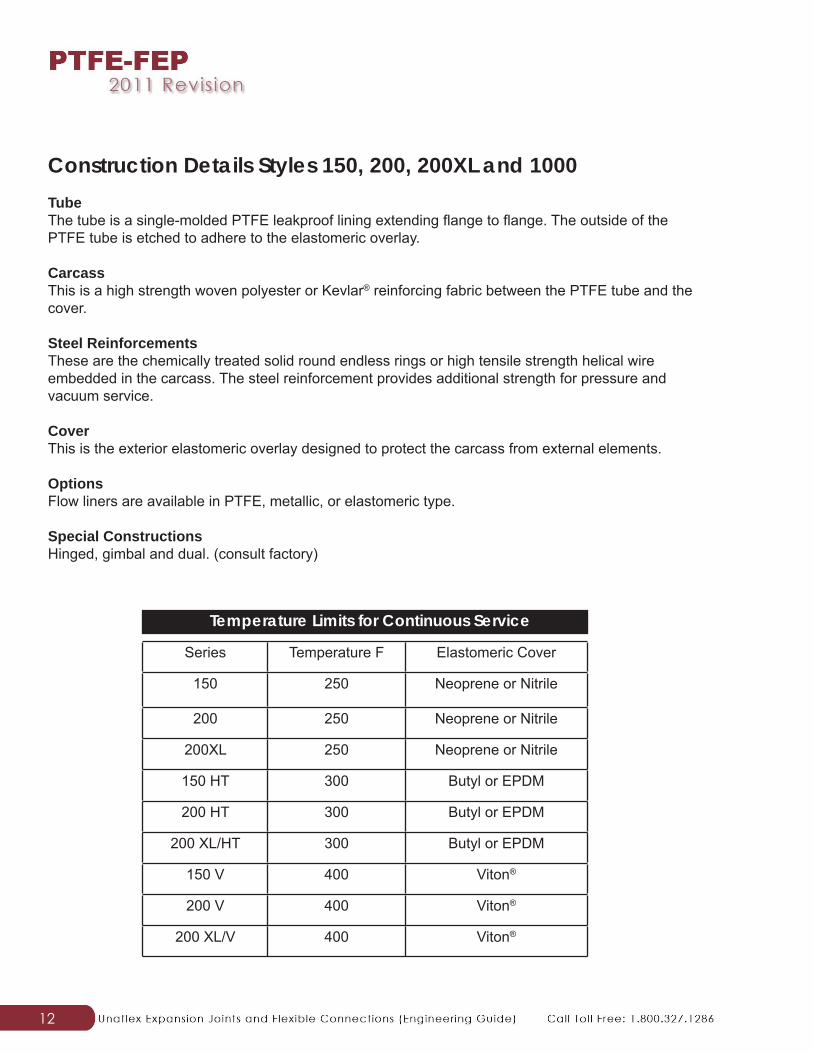
Construction Details Styles 150, 200, 200XL and 1000TubeThe tube is a single-molded PTFE leakproof lining extending fl ange to fl ange. The outside of the PTFE tube is etched to adhere to the elastomeric overlay.
CarcassThis is a high strength woven polyester or Kevlar® reinforcing fabric between the PTFE tube and the cover.
Steel ReinforcementsThese are the chemically treated solid round endless rings or high tensile strength helical wire embedded in the carcass. The steel reinforcement provides additional strength for pressure and vacuum service.
CoverThis is the exterior elastomeric overlay designed to protect the carcass from external elements.
OptionsFlow liners are available in PTFE, metallic, or elastomeric type.
Special ConstructionsHinged, gimbal and dual. (consult factory)
Series Temperature F Elastomeric Cover
150 250 Neoprene or Nitrile
200 250 Neoprene or Nitrile
200XL 250 Neoprene or Nitrile
150 HT 300 Butyl or EPDM
200 HT 300 Butyl or EPDM
200 XL/HT 300 Butyl or EPDM
150 V 400 Viton®
200 V 400 Viton®
200 XL/V 400 Viton®
Temperature Limits for Continuous Service
13
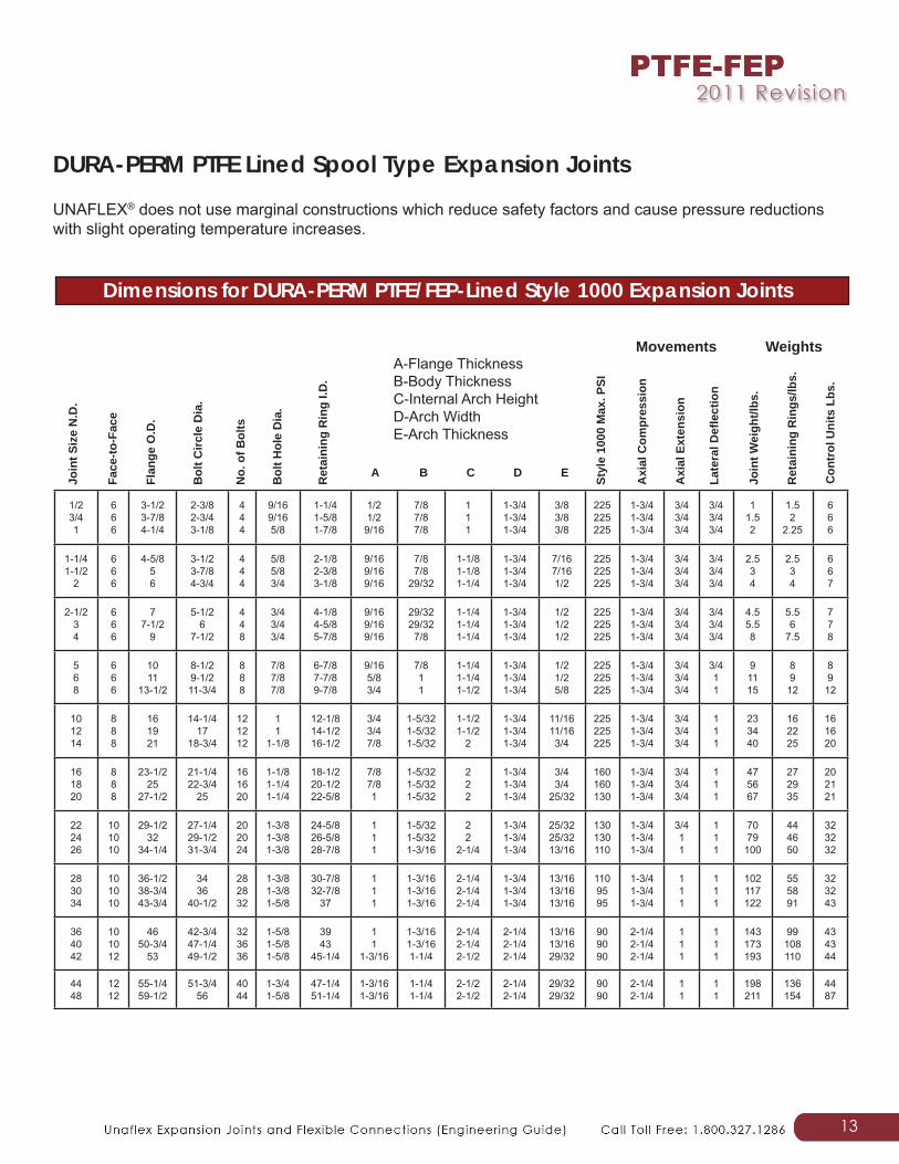
UNAFLEX® does not use marginal constructions which reduce safety factors and cause pressure reductions with slight operating temperature increases.
DURA-PERM PTFE Lined Spool Type Expansion Joints
1/23/41
666
3-1/23-7/84-1/4
2-3/82-3/43-1/8
444
9/169/165/8
1-1/41-5/81-7/8
1/21/29/16
7/87/87/8
111
1-3/41-3/41-3/4
3/83/83/8
225225225
1-3/41-3/41-3/4
3/43/43/4
3/43/43/4
11.52
1.52
2.25
666
1-1/41-1/2
2
666
4-5/856
3-1/23-7/84-3/4
444
5/85/83/4
2-1/82-3/83-1/8
9/169/169/16
7/87/8
29/32
1-1/81-1/81-1/4
1-3/41-3/41-3/4
7/167/161/2
225225225
1-3/41-3/41-3/4
3/43/43/4
3/43/43/4
2.534
2.534
667
2-1/234
666
77-1/2
9
5-1/26
7-1/2
448
3/43/43/4
4-1/84-5/85-7/8
9/169/169/16
29/3229/32
7/8
1-1/41-1/41-1/4
1-3/41-3/41-3/4
1/21/21/2
225225225
1-3/41-3/41-3/4
3/43/43/4
3/43/43/4
4.55.58
5.56
7.5
778
568
666
1011
13-1/2
8-1/29-1/211-3/4
888
7/87/87/8
6-7/87-7/89-7/8
9/165/83/4
7/811
1-1/41-1/41-1/2
1-3/41-3/41-3/4
1/21/25/8
225225225
1-3/41-3/41-3/4
3/43/43/4
3/411
91115
8912
89
12
101214
888
161921
14-1/417
18-3/4
121212
11
1-1/8
12-1/814-1/216-1/2
3/43/47/8
1-5/321-5/321-5/32
1-1/21-1/2
2
1-3/41-3/41-3/4
11/1611/163/4
225225225
1-3/41-3/41-3/4
3/43/43/4
111
233440
162225
161620
161820
888
23-1/225
27-1/2
21-1/422-3/4
25
161620
1-1/81-1/41-1/4
18-1/220-1/222-5/8
7/87/81
1-5/321-5/321-5/32
222
1-3/41-3/41-3/4
3/43/4
25/32
160160130
1-3/41-3/41-3/4
3/43/43/4
111
475667
272935
202121
222426
101010
29-1/232
34-1/4
27-1/429-1/231-3/4
202024
1-3/81-3/81-3/8
24-5/826-5/828-7/8
111
1-5/321-5/321-3/16
22
2-1/4
1-3/41-3/41-3/4
25/3225/3213/16
130130110
1-3/41-3/41-3/4
3/411
111
7079
100
444650
323232
283034
101010
36-1/238-3/443-3/4
3436
40-1/2
282832
1-3/81-3/81-5/8
30-7/832-7/8
37
111
1-3/161-3/161-3/16
2-1/42-1/42-1/4
1-3/41-3/41-3/4
13/1613/1613/16
1109595
1-3/41-3/41-3/4
111
111
102117122
555891
323243
364042
101012
4650-3/4
53
42-3/447-1/449-1/2
323636
1-5/81-5/81-5/8
3943
45-1/4
11
1-3/16
1-3/161-3/161-1/4
2-1/42-1/42-1/2
2-1/42-1/42-1/4
13/1613/1629/32
909090
2-1/42-1/42-1/4
111
111
143173193
99108110
434344
4448
1212
55-1/459-1/2
51-3/456
4044
1-3/41-5/8
47-1/451-1/4
1-3/161-3/16
1-1/41-1/4
2-1/22-1/2
2-1/42-1/4
29/3229/32
9090
2-1/42-1/4
11
11
198211
136154
4487
Join
t Siz
e N
.D.
Face
-to-F
ace
Flan
ge O
.D.
Bol
t Circ
le D
ia.
No.
of B
olts
Bol
t Hol
e D
ia.
Ret
aini
ng R
ing
I.D.
A B C D E
Styl
e 10
00 M
ax. P
SI
Axi
al C
ompr
essi
on
Axi
al E
xten
sion
Late
ral D
efl e
ctio
n
Join
t Wei
ght/l
bs.
Ret
aini
ng R
ings
/lbs.
Con
trol
Uni
ts L
bs.
Movements Weights
Dimensions for DURA-PERM PTFE/FEP-Lined Style 1000 Expansion Joints
A-Flange ThicknessB-Body ThicknessC-Internal Arch HeightD-Arch WidthE-Arch Thickness
14
PTFE Lined Serpent HoseUnafl ex® combines the advantages of lightweight yet durable rubber hose, with PTFE’s unsurpassed resistance to virtually all chemicals except molten Alkali metals such as Potassium, Lithium, and radium, as well as Fluorochemicals.
Serpent PTFE lined hose is an excellent choice for transfer service of acids, ester, acetone, aromatic hydrocarbons, organic chemicals and alcohols. Unafl ex® hose is steam cleanable for short durations and is excellent for food handling services.
PTFE/Flexible Rubber Pipe Connectors
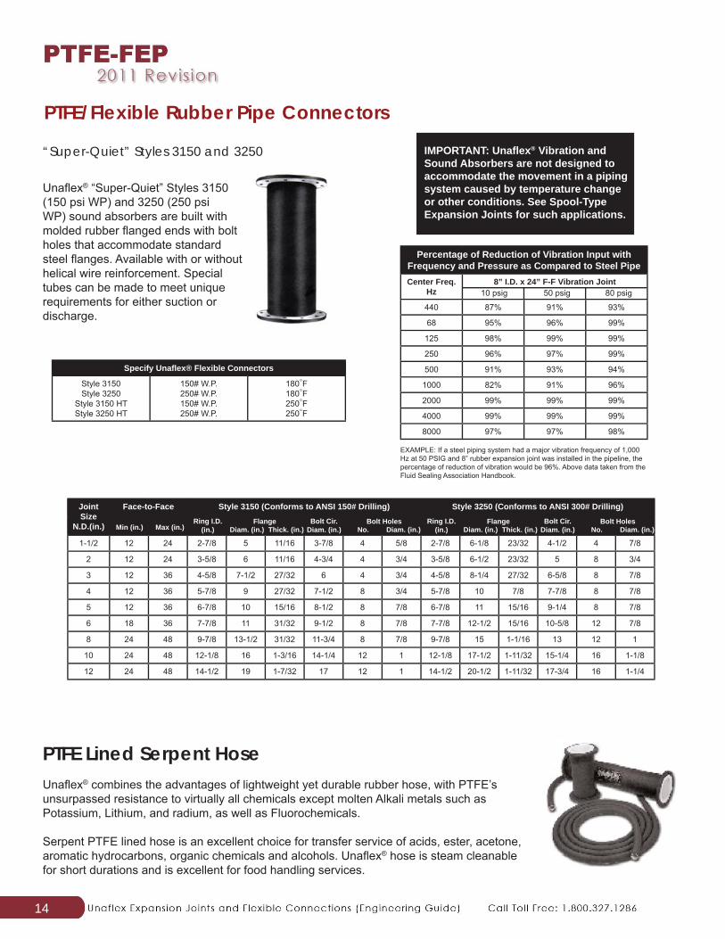
Unafl ex® “Super-Quiet” Styles 3150 (150 psi WP) and 3250 (250 psi WP) sound absorbers are built with molded rubber fl anged ends with bolt holes that accommodate standard steel fl anges. Available with or without helical wire reinforcement. Special tubes can be made to meet unique requirements for either suction or discharge.
“Super-Quiet” Styles 3150 and 3250 IMPORTANT: Unafl ex® Vibration and Sound Absorbers are not designed to accommodate the movement in a piping system caused by temperature change or other conditions. See Spool-Type Expansion Joints for such applications.
Specify Unafl ex® Flexible Connectors
Style 3150Style 3250
Style 3150 HTStyle 3250 HT
150# W.P.250# W.P.150# W.P.250# W.P.
180◦F180◦F250◦F250◦F
Percentage of Reduction of Vibration Input with Frequency and Pressure as Compared to Steel PipeCenter Freq.
Hz8” I.D. x 24” F-F Vibration Joint
440 87% 91% 93%
68 95% 96% 99%
125 98% 99% 99%
250 96% 97% 99%
500 91% 93% 94%
1000 82% 91% 96%
2000 99% 99% 99%
4000 99% 99% 99%
8000 97% 97% 98%
EXAMPLE: If a steel piping system had a major vibration frequency of 1,000 Hz at 50 PSIG and 8” rubber expansion joint was installed in the pipeline, the percentage of reduction of vibration would be 96%. Above data taken from the Fluid Sealing Association Handbook.
10 psig 50 psig 80 psig
Joint Size
N.D.(in.)
Face-to-Face Style 3150 (Conforms to ANSI 150# Drilling) Style 3250 (Conforms to ANSI 300# Drilling)
1-1/2 12 24 2-7/8 5 11/16 3-7/8 4 5/8 2-7/8 6-1/8 23/32 4-1/2 4 7/8
2 12 24 3-5/8 6 11/16 4-3/4 4 3/4 3-5/8 6-1/2 23/32 5 8 3/4
3 12 36 4-5/8 7-1/2 27/32 6 4 3/4 4-5/8 8-1/4 27/32 6-5/8 8 7/8
4 12 36 5-7/8 9 27/32 7-1/2 8 3/4 5-7/8 10 7/8 7-7/8 8 7/8
5 12 36 6-7/8 10 15/16 8-1/2 8 7/8 6-7/8 11 15/16 9-1/4 8 7/8
6 18 36 7-7/8 11 31/32 9-1/2 8 7/8 7-7/8 12-1/2 15/16 10-5/8 12 7/8
8 24 48 9-7/8 13-1/2 31/32 11-3/4 8 7/8 9-7/8 15 1-1/16 13 12 1
10 24 48 12-1/8 16 1-3/16 14-1/4 12 1 12-1/8 17-1/2 1-11/32 15-1/4 16 1-1/8
12 24 48 14-1/2 19 1-7/32 17 12 1 14-1/2 20-1/2 1-11/32 17-3/4 16 1-1/4
Min (in.) Max (in.)Ring I.D.
(in.)Flange
Diam. (in.) Thick. (in.)Bolt Cir.
Diam. (in.)Bolt Holes
No. Diam. (in.)Ring I.D.
(in.)Flange
Diam. (in.) Thick. (in.)Bolt Cir.
Diam. (in.)Bolt Holes
No. Diam. (in.)
15
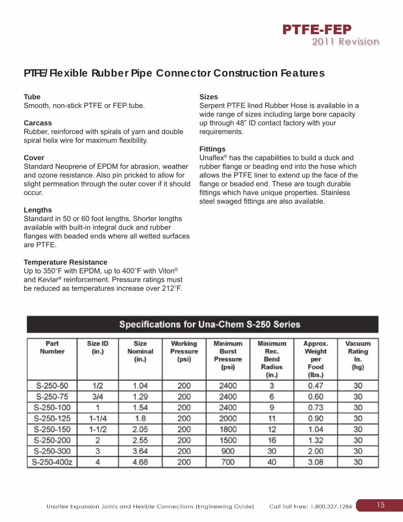
TubeSmooth, non-stick PTFE or FEP tube.
CarcassRubber, reinforced with spirals of yarn and double spiral helix wire for maximum fl exibility.
CoverStandard Neoprene of EPDM for abrasion, weather and ozone resistance. Also pin pricked to allow for slight permeation through the outer cover if it should occur.
LengthsStandard in 50 or 60 foot lengths. Shorter lengths available with built-in integral duck and rubber fl anges with beaded ends where all wetted surfaces are PTFE.
Temperature ResistanceUp to 350◦F with EPDM, up to 400◦F with Viton® and Kevlar® reinforcement. Pressure ratings must be reduced as temperatures increase over 212◦F.
SizesSerpent PTFE lined Rubber Hose is available in a wide range of sizes including large bore capacity up through 48” ID contact factory with your requirements.
FittingsUnafl ex® has the capabilities to build a duck and rubber fl ange or beading end into the hose which allows the PTFE liner to extend up the face of the fl ange or beaded end. These are tough durable fi ttings which have unique properties. Stainless steel swaged fi ttings are also available.
PTFE/Flexible Rubber Pipe Connector Construction Features
16
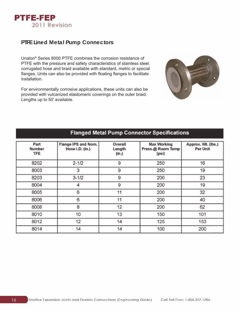
PTFE Lined Metal Pump Connectors
Unalon® Series 8000 PTFE combines the corrosion resistance of PTFE with the pressure and safety characteristics of stainless steel. corrugated hose and braid available with standard, metric or special fl anges. Units can also be provided with fl oating fl anges to facilitate installation.
For environmentally corrosive applications, these units can also be provided with vulcanized elastomeric coverings on the outer braid. Lengths up to 50’ available.
17
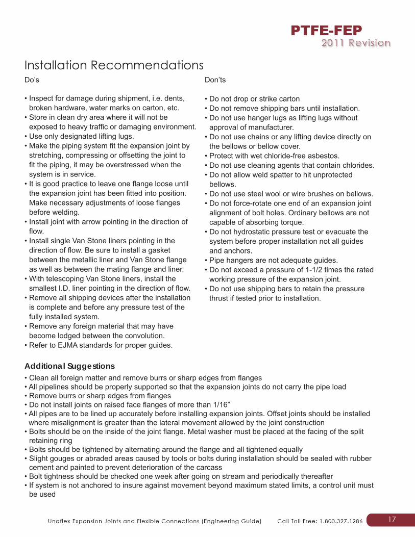
Do’s
• Inspect for damage during shipment, i.e. dents, broken hardware, water marks on carton, etc.
• Store in clean dry area where it will not be exposed to heavy traffi c or damaging environment.
• Use only designated lifting lugs.• Make the piping system fi t the expansion joint by
stretching, compressing or offsetting the joint to fi t the piping, it may be overstressed when the system is in service.
• It is good practice to leave one fl ange loose until the expansion joint has been fi tted into position. Make necessary adjustments of loose fl anges before welding.
• Install joint with arrow pointing in the direction of fl ow.
• Install single Van Stone liners pointing in the direction of fl ow. Be sure to install a gasket between the metallic liner and Van Stone fl ange as well as between the mating fl ange and liner.
• With telescoping Van Stone liners, install the smallest I.D. liner pointing in the direction of fl ow.
• Remove all shipping devices after the installation is complete and before any pressure test of the fully installed system.
• Remove any foreign material that may have become lodged between the convolution.
• Refer to EJMA standards for proper guides.
Don’ts
• Do not drop or strike carton• Do not remove shipping bars until installation.• Do not use hanger lugs as lifting lugs without
approval of manufacturer.• Do not use chains or any lifting device directly on
the bellows or bellow cover.• Protect with wet chloride-free asbestos.• Do not use cleaning agents that contain chlorides.• Do not allow weld spatter to hit unprotected
bellows.• Do not use steel wool or wire brushes on bellows.• Do not force-rotate one end of an expansion joint
alignment of bolt holes. Ordinary bellows are not capable of absorbing torque.
• Do not hydrostatic pressure test or evacuate the system before proper installation not all guides and anchors.
• Pipe hangers are not adequate guides.• Do not exceed a pressure of 1-1/2 times the rated
working pressure of the expansion joint.• Do not use shipping bars to retain the pressure
thrust if tested prior to installation.
Installation Recommendations
• Clean all foreign matter and remove burrs or sharp edges from fl anges• All pipelines should be properly supported so that the expansion joints do not carry the pipe load• Remove burrs or sharp edges from fl anges• Do not install joints on raised face fl anges of more than 1/16”• All pipes are to be lined up accurately before installing expansion joints. Offset joints should be installed
where misalignment is greater than the lateral movement allowed by the joint construction• Bolts should be on the inside of the joint fl ange. Metal washer must be placed at the facing of the split
retaining ring• Bolts should be tightened by alternating around the fl ange and all tightened equally• Slight gouges or abraded areas caused by tools or bolts during installation should be sealed with rubber
cement and painted to prevent deterioration of the carcass• Bolt tightness should be checked one week after going on stream and periodically thereafter• If system is not anchored to insure against movement beyond maximum stated limits, a control unit must
be used
Additional Suggestions
18
Technical Information
Flange Bolt Torquing for Unafl ex® PTFE-lined piping products
General techniques utilized to install fl anged carbon steel piping systems may also be applied to Unafl ex® PTFE-lined piping systems.
When assembling fl ange connections, it is recommended that a full complement of clean, new and high-strength A193-B7 bolting is consistently utilized. When stainless steel bolting is used, consist of A 320/A320M Class 2 B8 (304 SS) or Class 2 B8M (316 SS) with A 194/A194M Grade 8 or 8A Nuts (for 304 SS) or Grade 8M or 8MA (for 316 SS). When other bolting materials are employed, user should ensure new bolting material strength properties exceed the calculated bolt stress values generated in establishing the piping connection.The following practices are strongly recommended: • Always utilized fl at washers on both sides of the connection • Ensure that the fl ange bolts are tightened with a calibrated torque wrench expressly for the specifi ed
bolt torques. Note: For anti-seize compounds, the torque values may vary. Please contact Unafl ex® for more information
• Firmly secure the fl ange bolts with a torque wrench utilizing a “crisscross” pattern that alternately tightens the bolts located 180 degrees apart
• Employing the above mentioned pattern, tighten the bolts in 20% increments of the fi nal bolt torque until 80% of the fi nal bolt torque has been accomplished
• To tighten the fi nal torque values, fi rmly tighten bolts sequentially clockwise one time around the fl ange. This procedure ensures the bolts have been evenly stressed
• Extreme caution should be taken to avoid over-torquing which can result in damage to plastic sealing surfaces
NOTE: When bolting dissimilar materials, always tighten to the lowest recommended torque of the components in the joint. Employing higher torques may cause excessive deformation of the “softer” material contained in the joint. Position a ½” thick spacer between Unafl ex PTFE-lined pipe or fi ttings and other plastic-lined components, particularly valves, should differences in the diameters of the raised plastic faces occur. *Belleville washers are not recommended for use with PTFE-lined products. RetorquingA retorque should be applied a minimum of 24 hours after the initial torque or after the fi rst thermal cycle. Retorquing enables seating of the plastic and allows for the relaxation of the bolts. In the event that the system is intended to perform at elevated temperatures, hot water should be circulated at the maximum operating temperature of the process (if possible) for at least 24 hours. This process will allow the pipe system to experience one full thermal cycle.
After cool-down, retorquing of the system should be completed. Torquing need only be completed on the system in the ambient, cooled state and never while the process is at an elevated temperature. This could cause excessive force to be exerted to the plastic faces. Never attempt to disassemble a fl ange joint in a hot system. Wait until the system has cooled to ambient temperature.
19
Technical Information
Hydrotesting Typically after initial torque and retorque, a hydrotest should be carried out utilizing ANSI requirements. Experience has demonstrated that if the aforementioned procedure is adhered to, very few, if any fl ange joints will fail the hydrotest. If a fl ange joint leaks, fi rst re-check the torque values and tighten in 10% increments over the specifi ed bolt torques until completely sealed. If, however, 150% of the specifi ed torque value has been reached and the fl ange joint continues to leak, stop the process and disassemble the fl ange joint. It is likely that something else is wrong, i.e, a scratched plastic face.The hydrotest must be successfully completed, and any existing leaks corrected before the pipeline can be approved and commissioned.
Annual RetorquingRetorquing should be completed a minimum of annually thereafter. This is particularly crucial if the process line experiences elevated temperatures or extreme ambient temperature exposure. Torquing should only be completed on the system in the ambient, cooled state. Never attempt this process at an elevated temperature as damaging excessive force may be applied to the plastic faces.
UNAFLEXE x c e l l e n c e i n M a n u f a c t u r i n g
®
LLC.
STANDARD WARRANTYAll merchandise sold by UNAFLEX® is subject to this Standard Warranty. Our products are warranted to be free from defects in material or workmanship. Our liability for breach of any and all warranties, expressed or implied, is limited to refunding our invoice price of the product, or at our option, to replacement of the product. If any product manufactured by UNAFLEX® is found by us to be defective either in material or workmanship, under proper usage and service, the invoice price will be refunded or at our option will be replaced free of charge including transportation charges, but not cost of installation. The refund of the invoice price or the replacement of the product is the maximum liability of the company. The sale of our products under any other warranty or guarantee, expressed or implied, is not authorized by the company.
Technical statements and engineering data in this catalog is the most accurate information available at the time of printing and are subject to change without notice. As UNAFLEX® does not supervise or control the use of our products, UNAFLEX® cannot be responsible for improper use or misapplication of catalog data.
ISO 9001:2008 CERTIFIED
CALL TOLL FREE: 1-800-327-1286
Visit www.unafl ex.com to download our full line of product catalogs
3901 NE 12th Avenue • Pompano Beach, FL 33064Mail: P.O. BOX 5088 • Ft. Lauderdale, FL 33310
TOLL FREE: 1-800-327-1286Ph: 954.943.5002 • Fax: 954.941.7968
Factory Facilities in Anderson, SC. | Warehouse Facilities in Houston, TX
scott
brochure stamp