TWO-FOR-ONE TACTICAL SHELTER LOADS · TWO-FOR-ONE TACTICAL SHELTER ... level 17.5 COSMIC*NASTRAN.I,...
40
II TECHNICAL REPORT NATICK/TR-81/016 00 RESPONSEOFA TWO-FOR-ONE TACTICAL SHELTER TO RACKING LOADS BY ARTHUR R. JOHNSON : iC AUG 4 1981 " A APPROVED FOR PUBLIC RELEASE; JANUARY1981 DISTRIBUTION UNLIMITED. I I AERO-MECHANICAL ENGINEERING LABORATORY 81 8 04 009 t ,
Transcript of TWO-FOR-ONE TACTICAL SHELTER LOADS · TWO-FOR-ONE TACTICAL SHELTER ... level 17.5 COSMIC*NASTRAN.I,...

IITECHNICAL REPORTNATICK/TR-81/016
00
RESPONSEOFATWO-FOR-ONE TACTICAL SHELTER
TO RACKING LOADS
BY ARTHUR R. JOHNSON
: iCAUG 4 1981 "
A
APPROVED FOR PUBLIC RELEASE; JANUARY1981DISTRIBUTION UNLIMITED. I
I
AERO-MECHANICAL ENGINEERING LABORATORY81 8 04 009
t ,

Approved for public release; distribution unlimited.
Citation of trade names in this report does notconstitute an official indorsement or approval of theuse of such items.
Destroy this report when no longer needed. Do notreturn it to the originator.

UNCLASSIFIEDSECURITY CLASSIFICATION OF THIS PAGE (When Date Entered)
REPORT DOCUMENTATION PAGE E SPoRE COMPLETING FORM
i. REPORT NUMBER 2. GOVT ACCESSION NO 3,ECIPIENT'S CATALOG.NUMBER
?1 f~4. TITLE (and Subtitle) S. TYPE OF REPORT & PERIOD COVERED
,RESPONSE OF A 3WO-,FOR-.NE TACTICAL AugwlS-Janm48:SHELTER TO RAC&ING fLOADS, 5. PERFORMING ORG. REPORT NUMBER
7. AUTHOR(I) S. CONTRACT OR GRANT NUMBER(&)
Arthur R.Johnson/
9. PERFORMING ORGANIZATION NAME AND ADDRESS 10. PROGRAM ELEMENT PROJECT, TASKUS Army Natick Research & Development Laboratories AREA A WORK UNIT NUMBERS
ATTN: DRDNA-UE . 62723ANatick, MA 01760 /, L 1L162723A427 01003BG
It. CONTROLLING OFFICE NAME AND ADDRESS 12. REPORT DATE
US Army Natick Research & Development Laborator Jas) Jan 08lATTN: DRDNA-UE NL NUMBER OF PAGES
Natick, MA 01760 4114. MONITORING AGENCY NAME & ADORESS(if dilferent from Controlling Office) 1S. SECURITY CLASS. (of thle repot)
UNCLASSIFIED
t" 1 " 1to5a. DECLASSI FICATION/ DOWNGRADING/ j- ~SCHEDU LE
1I. DISTRIBUTI T:,&ZdI4tNT (of li Report)
Approved for public release; distribution unlimited.(i ./ - ,
__.,___.__-__,_ _._____ -i" /-17. DISTRIBUTION STATEMENT (of the abetr ct entered In lolk 20, It diffLmmtaxtJm Rapat)
IS. SUPPLEMENTARY NOTES
19. KEY WORDS (Continue on reverse side if nocoeeary end Identify by block namber)
ISO SHELTERS FINITE ELEMENTS MODELSARMY SHELTERS CONTAINERS BEAM (STRUCTURAL)STRUCTURAL BEHAVIOR TACTICAL SHELTERS LOADS (FORCES)STRESSES LOAD CARRYING
20. ABSTRACT 'r-tAtmuo m evm efdo N necessary and Iditity by block rnowb,)
- A finite element model of a two-for-one tactical shelter is presented. The model iscompatible with the COSMIC*NASTRAN finite element program. Both beam and compositeplate elements are used in the model. The geometric properties of the beams are given intables. The shelter's response to racking loads is calculated for one transverse loading conditionon each end of the shelter. Two computer models are used to analyze the response at thepersonnel door end and seven models for the cargo door end. The models represent differentmethods for using the doors as load-carrying members. Stresses in the doorframes, loads on -!
DD JAM NIW EIlTON OP I NOV 61 IS OBSOLETE '" "j~
W J W3 oUNCLASSIFIED I -AYSECURITY CLASSIFICATION OF THIS PAGE (When Dais Entared)

UNCLASSIFIEDSECURITY CLASSIFICATION OF THIS PAGE(Wha Data Etetd0
20. Abstract (cont'd)
\the door hinges, and loads on the corners of the doors are all determined and discussed. Thecomputer models and the relation between the computed responses and the actual structuralresponse are also discussed. It is shown that the framework cannot sustain the racking loadwithout using the doors as load-carrying members, and when the doors are used, the doorhinge loads are large.
UNCLASSIFIEDSECURITY CLASSIFICATION OF THIS PAGE(Wihen Data nt.r.d)

PREFACE
The US Army Natick Research and Development Laboratories are developing a familyof rigid wall tactical shelters. This study is one of a series of in-house analytical and numericalstudies being made to develop a detailed engineering understanding of how tactical sheltersrespond to environmental loadings. Two other reports in this series can be obtained fromNTIS. Their title and order numbers are "Finite Element Analysis of a Statically LoadedISO Tactical Shelter," AD-A075807, and "A Study of Transversely Loaded Panels Used inTactical Shelters," AD-A085138. The work reported in this study is of a applied engineeringcharacter and was initiated after two contractor-supplied two-for-one shelters failed to passthe transverse racking tests. The results of this effort explain why the shelter failed the testand suggest modifications to improve the shelter's ability to resist the transverse racking loads.
The rigid wall tactical shelter fabrication drawings use U.S. Customary units fordimensioning. This report utilized these drawings and is also, therefore, in British units. Aconversion table between U.S. Customary and SI units is included on page 7.
The author would like to thank Mr. John Roche and Mr. James McLaughlin for theirassistance in processing computer runs and obtaining data for this study.
Accer!min
LL
NTIS c -
.... :,T
D7U. ,"}
I ] , . ...."r i A
ft1,
-C -,.

TABLE OF CONTENTS
Page
LIST OF ILLUSTRATIONS 4
1. INTRODUCTION 9
2. THE GLOBAL FINITE ELEMENT MODEL 9
3. MODELING AND ANALYSES OF END WALLS SUBJECTED TO 11RACKING LOADS
4. LOADS ON HINGES AND DOOR CORNERS 13
5. CONCLUSION 14
6. RECOMMENDATIONS 14
£1
3
i~tEZ AMJ U.-MAlE-NT Flum
LIST OF ILLUSTRATIONS
Page
Figure 1. Shelter components used in finite element model 15
Figure 2. Nodal point identification numbers 16
Figure 3. Quadrilateral plate element numbers 17
Figure 4. Beam element numbers for frame 18
Figure 5. Beam element numbers for panel close-out extrusions 19
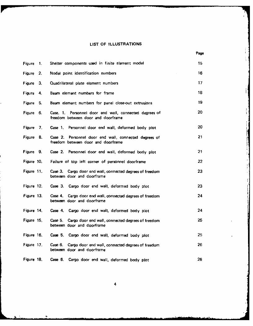
Figure 6. Case. 1. Personnel door end wall, connected degrees of 20freedom between door and doorframe
Figure 7. Case 1. Personnel door end wall, deformed body plot 20
Figure 8. Case 2. Personnel door end wall, connected degrees of 21freedom between door and doorframe
Figure 9. Case 2. Personnel door end wall, deformed body plot 21
Figure 10. Failure of top left corner of personnel doorframe 22
Figure 11. Case 3. Cargo door end wall, connected degrees of freedom 23between door and doorframe
Figure 12. Case 3. Cargo door end wall, deformed body plot 23
Figure 13. Case 4. Cargo door end wall, connected degrees of freedom 24between door and doorframe
Figure 14. Case 4. Cargo door end wall, deformed body plot 24
Figure 15. Case 5. Cargo door end wall, connected degrees of freedom 25between door and doorframe
Figure 16. Case 5. Cargo door end wall, deformed body plot 25
Figure 17. Case 6. Cargo door end wall, connected degrees of freedom 26between door and doorframe
Figure 18. Case 6. Cargo door end wall, deformed body plot 26
4

LIST OF ILLUSTRATIONS (cont'd)
Page
Figure 19. Case 7. Cargo door end wall, connected degrees of freedom 27between door and doorframe
Figure 20. Case 7. Cargo door end wall, deformed body plot 27
Figure 21. Case 8. Cargo door end wall, connected degrees of freedom 28
between door and doorframe
Figure 22. Case 8. Cargo door end wall, deformed body plot 28
Figure 23. Case 9. Cargo door end wall, connected degrees of freedom 29between door and doorframe
Figure 24. Case 9. Cargo door end wall, deformed body plot 29
Figure 25. Location of nodes on the boundary of the doors 30
5
. ..... .

LIST OF ILLUSTRATIONS (cont'd)
Page
Table 1. Conversion table. British units to SI units 7
Table 2. Geometric properties for beam elements with property 31numbers 150, 170, 200, and 210
Table 3. Geometric properties for beam elements with property 32numbers 220, 300, 400, and 410
Table 4. Geometric properties for beam elements with property 33numbers 500, 510, 601, and 702
Table 5. Geometric properties for beam elements with property 34numbers 703, 801, 802, 803, and 804
Table 6. Sample stress data for personnel door end 35
Table 7. Sample stress data for cargo door end 36
Table 8. Forces on doorframe due to door hinges and door corners 37
at personnel door end
Table 9. Forces on doorframe and between doors due to door hinges, 38door corners, and adjacent door at cargo door end
[
6

Table 1. Conversion table. U.S. Customary units to SI units
To convert U.S. Customaryunits to SI units
Quantity U.S. Customary SI Units multiply by
Mass pounds mass kilograms 0.455
Force pounds force newtons 4.45
Length inch meter 0.0254
foot meter 0.305
yard meter 0.91
Area square inch square meters 6.45 x 10⁻⁴
square foot square meters 0.093
Volume cubic inches cubic meters 1.64 x 10. !
cubic feet cubic meters 0.0283
Density pounds per kilograms per 2.77 x 10⁴
cubic inch cubic meter
ounces grams per 34
square meter
Tension pounds per inch newtons per 176
meter
Moment ofInertia (inches) 4 (meters) 4 4.1 x 10'
Modulus of pounds per newtons perElasticity square inch square meter 6.89 x 10³
and Stress
7

RESPONSE OF A TWO-FOR-ONE TACTICAL
SHELTER TO RACKING LOADS
1. INTRODUCTION
Extensive testing of prototype two-for-one tactical shelters indicated that the shelters werenot able to pass the ISO racking tests without sustaining physical damage. It then becameof interest to understand how the two-for-one tactical shelters respond to ISO racking loads.The calculations made in this study were directed at evaluating the load-carrying capabilityof the current design. The analytical study is broad enough so that the mechanism of loaddistribution in the frame-and-panel end wall can be understood for a number of modificationsof the end walls. Nine different conditions were considered. Two conditions for the personneldoor end and seven conditions for the cargo door end.
In Section 2 of this study the finite element model of the two-for-one tactical shelteris described. The nodal points, beams elements, and plate elements are identified. Theirorientation in spa-e is shown and their geometric properties are given. In Section 3 the detailsof each model of the end walls are discussed. Also, scaled plots of the deformed end walls,and brief descriptions of the stresses in the end wall frames are given for each case analyzed.In Section 4 of this study a summary of the door hinge loads is given. The last sectionof this study contains comments on the limitations of the analysis and on the design of theend walls.
2. THE GLOBAL FINITE ELEMENT MODEL
The finite element model used is a modification of an undocumented finite element modelreceived with the first prototype Army Standard Family One-Side Expandable Shelter. Themodel was compatible with MSC*NASTRAN only and it contained errors. Most of the errorsinvolved incorrect orientation of beam elements. The panel close-out extrusions which werenot in the model were included in the new model and the model was made compatible withlevel 17.5 COSMIC*NASTRAN.I, 2 Figure 1 shows the components of the shelter includedin the finite element model (the door frames are built into the end wall panels). The meshused to discretize the shelter is shown in Figure 2 along with the nodal (GRID) pointidentification numbers. The sandwich panels were modeled with CQUAD1 rectangular plateelements. These plate elements model bending, transverse shear, and inplane membraneresponses of the sandwich panel. The plate elements are shown in Figure 3 and the beamelements used to model the framework are shown in Figure 4. These frame members includethe floor frame, the roof hat beam, the corner posts and the cargo doorframe. The beamelements used to model the panel close-out extrusions are shown in Figure 5. The personneldoorframe is included in the close-out extrusion beam elements.
"H. G. Schaeffer. MSC/NASTRAN Static and Normal Modes Analysis. Wallace Press, Inc.,Milford, New Hampshire, 1979.
2 The NASTRAN Theoretical Manual (Level 17.5). COSMIC, University of Georgia, Athens,Georgia, December 1978.
9
kCLDj PAG BLANK-NOT F7i1,
.9

For the GRID points associated only with plate elements the rotational degrees of freedom
about the normal to the plate elements were eliminated on the GRID cards (which define
active degrees of freec.om) when no beam elements were connected to the GRID points. The
components of the shelter were connected by writing the appropriate equations of constraintand using the MPC cards in NASTRAN to enforce them. Except for the doors, the constraintequations represent a rigid attachment of the degrees of freedom at the boundaries betweenthe components of the shelter. The connection of the doors to the doorframes is discussedin Section 3 of this study.
The geometric properties of the beams are given in Tables 1 to 4. There were 17 differentcross sections among the frame members used in the finite element model. The shapes ofthe cross sections, the local element coordinates at end A of the element, and the stress recoverypoints used for obtaining the bending stresses are also given in Tables 2 to 5.
The finite element model used in this study is useful for computing the overall structuralbehavior of the shelter. However, several comments about the model should be made. Thenodes used to represent the discretization of the personnel door end wall did not line upwith the nodes used to discretize the roof and the floor. This had no effect on the modelof the frame since NASTRAN has provisions for treating such cases when beam elements areused. No special treatment was given to the plate elements here. Thus, the plate elementsnear the top and bottom center of the personnel door end wall are not of the correct size.The author has chosen to leave the model this way since correction of the problem wouldresult in elements that are nearly congruent to the current elements. The resulting elementstiffness matrices would then also be nearly equal. Next, the model of the roof, floor, sidewalls, and personnel door wall included the effects of the panel close-out extrusions. However,the close-out extrusions were not included in the models of the doors. Thus, in the actualstructure the doors will be slightly stiffer than indicated in this study. The last commenton the model relates to numerical accuracy. The effect of the discretization on the numericalresults was not determined. However, the results from other studies conducted by the author 3 4
indicate that this model is sufficiently accurate for predicting the overall structural behaviorof the shelter.
3 Arthur R. Johnson. A Study of Transversely Loaded Panels Used in Tactical Shelters.Technical Report NATICK/TR-80/006, US Army Natick Research & Development Command,Natick, MA, 1979 (AD-A085138).
4 A. R. Johnson and V. P. Ciras. Finite Element Analysis of a Statically Loaded ISO TacticalShelter. Technical Report Natick/TR-79/023, US Army Natick Research & DevelopmentCommand, Natick, MA, (AD-A075807).
10

3. MODELING AND ANALYSES OF END WALLS SUBJECTED TO RACKING LOAI),
The doors used in the end walls do not fit tightly into the doorframes. There cr,:
nonmetallic shims attached to the corners of the doors and gaps ranging in size frn -1 3inch to 1/4 inch exist between the shims and the doorframe. Thus, when the shelter is (.t:url l..the doors move until they come in contact with the doorframe. During testing It was Odteti,ire(4that the doors contact the doorframe at low loads. Displacement data taken from tnt ,element analyses made in this study predict that if the gaps are about 1/8 inch then a rdcK1;,qload of 8.9 x 10³ lb will close the gaps at the personnel door end and a load of 5.9 x 10'lb will close the gaps at the cargo door end. A nonlinear analysis which would correctlymodel all the gaps was considered beyond the scope of this study. Instead, two sets of internalstructural forces and stresses were sought by modeling the end wall doorframe interaction twoways. First, the doors were assumed not to contact the doorframe at the door corners (doorswere attached to the doorframe only at the hinge locations). Second, the doors were assumedto be shimmed tightly so that no gaps existed. The structural analysis data from both ofthese situations was evaluated assuming that the actual structural response would yield resultsbetween the results for these two models. At the cargo door end further models wereconstructed to investigate the advantages associated with several methods of connecting thedoors to each other and to the doorframe.
a. Modeling and Analysis of Personnel Door End Wall
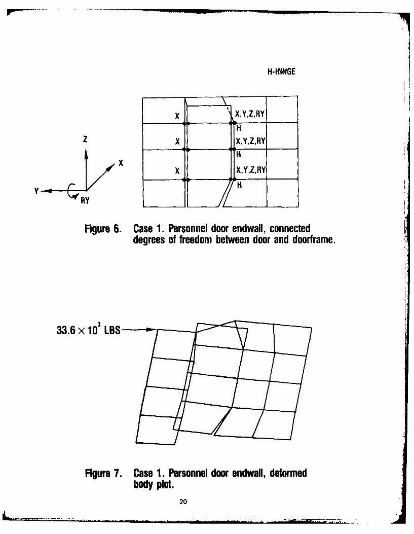
The racking load used to analyze the personnel door end wall's response to the rackingtest was a 33.6 x 10³ lb static load applied at node 100 in the negative y direction. Theshelter was pinned at all four bottom ISO fittings. That is, the x, y, and z translations atnodes 400, 410, 444, and 454 were enforced to zero. Two models, described below, of thepersonnel door end wall were made, and the deformations, stresses, and element nodal forceswere determined for each model. The connections between the personnel door and thedoorframe for the first case analyzed are shown in Figure 6. The connections represent thedoor being attached at the hinges and being restricted from swinging open. There is no contactbetween the door and the doorframe at the door's corners. This model represents the casewhen the gaps between the door and the doorframe are so large that when the shelter deforms,the gap is not closed by the relative movement between the door and the doorframe. Thedeformed body plot is shown in Figure 7. The apparent overlapping of the door and theend wall exists because the door and doorframe nodes are at the same initial location in thefinite element model. The plot indicates that the door header beam will be curved up onthe left and down on the right when the door does not interact with the header beam.
The connections between the door and the doorframe for the second case analyzed areshown in Figure 8; these connections cause the door to deform with the doorframe and thusstiffen the end wall. When these connections are used the numerical results indicate thatcompressive interactions exist between the door and the doorframe at the top left and bottomright corners of the door, and tensile interactions at the top right and bottom left cornersof the door. To simulate this case in the actual structure it would be necessary to restrainthe door and the doorframe from moving apart in the corners when tensile interactions wereobserved. The deformed body plot is shown in Figure 9. The plot indicates that the headerbeam is not deformed as in the previous case. Instead, in this case, the door restricts theheader beam from bending to the extent it did in the previous case.
11

Some of the maximum stresses in the loaded doorframe for each case are listed in Table 6.
The frame members were fabricated from 6061-T6 which has a yield strength of about
35 x 103 psi. Then, for the frame members considered in Table 6, case 1 is not acceptable.It is interesting to note that the highest stresses for case I are at the top left corner of thedoorframe which is where the frame failed in an actual test, see Figure 10. The results forthe actual structure would not be as severe as those indicated in case 1. When the shelterdeforms the gaps between the door and the doorframe close. The door and the doorframe
then interact in a manner similar to that predicted by case 2 and the stresses listed for case 2are at an allowable level. This does not necessarily imply that designing for case 2 will yieldan acceptable structure. Hinge forces, stress concentrations near joints, and joint loads mustalso be considered. The hinge forces are discussed in Section 4 of this study and an evaluationof the stress concentrations near the joints is beyond the scope of this effort.
b. Modeling and Analysis of the Cargo Door End Wall
The racking load used to analyze the cargo door end wall was a 33.6 x 10' lb staticload applied at node 110 in the negative y direction. The shelter was pinned again at allfour bottom ISO fittings. Six models of the end wall were made. The end wall models,the deformed body plots, and the maximum frame stresses are presented.
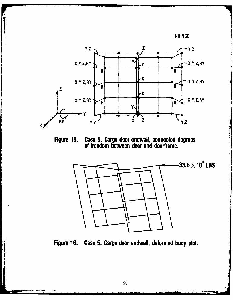
The constraints used to model cases 3 through 9 are shown in Figures 11, 13, 15, 17,19, 21 and 23, respectively. In case 3 the doors were attached to the doorframe at the hingepoints and were restricted from swinging open. The case 3 constraints represent the case whenlarge gaps exist between the cargo doors and between the cargo doors and the doorframe.The deformations are shown in Figure 12. The deformation plot indicates that the doorswill slide relative to each other. The external frame will be carrying the load (doors movedwithout deforming) and the header beam will contain a point of inflection at the center. Incase 4 constraints were added to simulate the doors being attached to the doorframe and thefloor in the corners of the hinged sides. The doors slide relative to each other. One doorjams against the header beam and the other door jams against the floor. The deformed bodyplot for case 4 is given in Figure 14. For these constraints the header beam and the floofwill tend to bow up and down, respectively. The case 5 constraints were made to simulatethe case when the right door in Figure 15 is attached to the header beam at the top andto the floor at the bottom, and both doors are attached to the doorframe in the cornerson the hinged sides. The deformations for case 5 are shown in Figure 16. When the right-handdoor is attached at the top to the header beam and at the bottom to the floor both theheader beam and the floor will tend to bow in the same direction. The case 6 constraintssimulate the case when both doors were attached top and bottom to the header beam andthe floor, respectively, and again the corners of the doors on the hinged side were attachedto the doorframe. The deformed body plot is given in Figure 18 and indicates that the doorswill be load-carrying members in this case (the doors are distorted). The constraints for case 7simulate the case when the doors are tied at the top and bottom, but unlike cases 4, 5, and6, the constraints simulating the doors being attached -o tie doorframe in the corners onthe hinged sides were not included. The deformation plot for case 7 is given in Figure 20and indicates that both the doors and the doorframe are carrying loads, since both are distorted.The constraints for case 8 simulate both doors being attuched at the top and bottom center
12
L

to the header beam and floor, respectively. Also, there were no corner constraintu wr it.
hinged sides of the doors. Thus, except for the hinged corners, case 8 is similar to case 6.
The deformed body plot for case 8 is shown in Figure 22. Again, both the doors and doorfralse
are distorted, indicating that they are both resisting the load. The constraints for the last
model, case 9, are the same as those of case 6 except the corner constraints (which causedtensile loads to exist between the doorframe corners and the door corners in case 6) werenot included, see Figure 23. Thus, case 9 represents the case when both doors are firmlyattached, top and bottom, to the doorframe and the doors are tightly shimmed at the doorframe
corners. The deformed body plot for case 9 is shown in Figure 24.
A summary of the maximum combined bending and axial stresses in the cargo doorframeis given in Table 7. The results indicate that when the doors are not distorted (cases 3, 4,and 5) the stresses in the doorframe are well above the yield value. Element numbers 604through 607 (the header beam) are highly stressed. However, when the doors are distorted(cases 6, 7, 8, and 9) the combined stresses in the doorframe beams are at an allowable level.Then, Table 7 and Figures 11 to 24 demonstrate numerically the shelter's response when thecargo doors are utilized, in several ways, as load-carrying members. In cases 4, 5 and 6 tensilereactions were obtained at varying locations on the door corners. That is, the corner constraintson the hinged sides did not always represent the doors jamming into the doorframe corners,but sometimes represented the door pulling on the doorframe in a corner. In case 9 therewere no tensile reactions at the doorframe corners. The results shown in Table 7 indicatethat ulilizing the cargo doors as load-carrying members by connecting them to the doorframeat the top and bottom center of the end wall can significantly reduce the stresses in thedoorframe.
4. LOADS ON HINGES AND DOOR CORNERS
The finite element model used in this study has three hinge connections between each
door and the doorframe. Three hinges were proposed for the original design, and the finiteelement discretization of the end walls was based on the original proposal of three hinges.The current structural design has four hinges between each door and the doorframe. Theresults discussed here apply to the three-hinge design.
The forces on the door corners and hinges are listed in Tables 8 and 9 for the personneland cargo door ends, respectively. Figure 25 shows the locations of the nodes on the boundaryof the doors and is intended to be used as a visual aid for the data in Tables 8 and 9. Thedata for the personnel door end indicates that there is a large difference in the hinge loadsbetween cases 3 and 4. The largest change is at the top hinge (node 503). Also, the corner
loads at node 500 are the largest reactions. In fact, the Z-component of the door cornerreaction at node 500 is about 2/3 the value of the applied load. At the cargo door endthe largest hinge loads occur in cases 7 and 8. In terms of the constraints on the cargo doors,the similarities between cases 7 and 8 are that the doors are attached to each other in shear,and that there are no corner reactions allowed between the doors and the doorframe. If thestresses are also considered, cases 6 and 9 are attractive. The hinge loads in case 6 are lowerthan those of case 9. In terms of a practical design, however, case 4 is difficult to implement.This is because the doorframe corners must be made to interact in both tension and compression
13
-- --- IPI -_ ... " I

with the doors. Case 9 is closely related to the case when the doors are shimmed at thedoorframe corners and attached to the doorframe at the top and bottom center of the endwall.
5. CONCLUSION
Nine structural models were developed to obtain structural analysis data on the responseof a two-for-one tactical shelter subjected to racking loads. The results of the analyses indicatethat the shelter will not pass the transverse racking test if the doors are not used as load-carryingmembers. Of the structural models utilizing the doors as load-carrying members those modelswhich also have the doors shimmed yield the best results. Also, when the doors are used,the hinge loads will be large. The actual nonlinear response of the shelter (response withgaps) was not determined in this study. Instead, a number of linear responses were determinedwhich provide a practical understanding of how the components of the shelter respond whenthe shelter is subjected to a transverse racking load. There is enough information in this reportto justify that the end walls should be redesigned. That is, the failures of the shelters testedwere due to the fact that the shelters were underdesigned for the loading requirements.
6. RECOMMENDATIONS
The end walls should be redesigned. In the new designs the doors should be used withthe doorframes to help carry the transverse racking loads. The free vertical edges of thepersonnel door and both cargo doors should be attached to both the top and bottom of thedoorframes. Shims should be used at the door corners and an effort should be made to keepthe gaps between the door-mounted shims and the doorframe as small as possible (to simulatecase 2 at the personnel door end and case 9 at the cargo door end). Further analyses shouldbe made to determine the hinge and door corner reactions for the case when four hinges connecteach door to the doorframe. The doors and hinges should then be designed to withstandthe required reactions. Alternatively, using the numerical data on the hinge loads anddoor-to-doorframe interaction loads provided in this study as general guidance, new prototypeend walls may be designed and tested.
14

CD
Eo
r-co
15=

1n CVC* L
Uj -* cc to
lw CJ
- CDj m~ t , ~ C
e'.e)
cc.
Sf~/u~L8IvN
C-4 16

- InN N)
( 0) ov -C.
CYzC-3 U.2
ML m
Cu-4
LLJ
-" X LL. J
CL LAJ
I- Z
-L zLli U uuj E (CD
4m Locn P LD aS L,
C',,C" cm t
C-4-
C40
Lfl
C,. -tr
CM0lI /m

uj ~ CD Czz Z
V-JU-
C~CD
T 7 co L
Ln co 0
V.4
C-1:
0O 0 UJ
"C- CC6
C*% CI COcc- LL . r
0 * 0 qm. co U

I--m at
z o
10 c"
c~cn
C
r--
C
ca,c2E
c~a,
LofCV r
19 '
H-HINGE
x X 'X,Y,Z,RYH
Z x X,Y,Z,RYI
yx
YR
Figure 6. Case 1. Personnel door endwall, connecteddegrees of freedom between door and doorframe.
Figure 7. Case 1. Personnel door endwall, deformedbody plot.
20

H-HINGE
RYY
X- ,X,Y,Z,RY
Z X, ,'X,Y,Z,RY
X ,X,Y,Z,RY
Y. Z
Figure 8. Case 2. Personnel door endwall, connected degreesof freedom between door and doorframe.
33.6 x 10' LBS.
Fgure 9. Case 2. Personnel door endwall, deformed
body plot.
21

ROOF
} i
ENDWALL
FIGURE 10. FAILURE OF TOP LEFT CORNER OF PERSONNEL DOORFRAME.
22

H-HINGE
X,Y,Z,RY ___ ___x -X,Y,Z.RY
H H
X,Y, Z, RY ->,. r X,Y,Z,RYz H H
X,Y,Z,RY 0H X,Y,Z,RY
RY
Figure 11. Case 3. Cargo door endwall, connected degreesof freedom between door and doorframe.
233

H-HINGE
Y,z zYz
X,Y,Z,RY -___ x -X Y Z,RYIfH H
z X,Y,Z,RY -,4x H X,Y,Z,RY
H X,Y,Z,RY
BYY Z YY
Figure 13. Case 4. Cargo door endwall, connected degreesof freedom between door and doorframe.
33.6 x 10' LBS
Figure 14. Case 4. Cargo door endwall, deformed body plot.
24
H -HINGE
Y,z zyz
X,Y,Z,RY H X,Y,Z,RY
XY,,RY H- X,Y,Z,RYz H
y
xRY y,z X ZY,z
Figure 15. Case 5. Cargo door endwall, connected degrees
of freedom between door and doorframe.
33.6 x10' L3
* I Figure 16. Case 5. Cargo door endwall, deformed body plot.
25

H-HINGE
Y,Z z zYz
X,Y,Z,RY ___x / X,Y,Z,RYH H
X,Y,Z, RY xX,Y,Z,RY4zH H
XYZRY H X,Y,Z,RY
YY
NY Y,z Y zi :Z
Figure 17. Case 6. Cargo door endwall, connected degreesof freedom between door and doortrame.
33.6 x10 LBS
Figure 18. Case 6. Cargo door eidwaII, deformed body plot.
26

H-HINGE
X,Y,ZRY A ~ x X,,Z,RYLH :1 0H
X, YZRY -. -- I X X,YZ,RYz H H
xX,Y,Z,RY HH X,Y,Z,RY
Y,Z
RY x
Figure 19. Case 7. Cargo door endwall, connected degreesof freedom between door and doorframe.
33.6 x10³ LBS
Figure 20. Case 7. Cargo door endwafl, deformed body plot.
i 27

H-HINGEz
X,Y,Z,RY Y, ___XYZR
H H
X,Y,Z,RY -,HA x . X,Y,Z,RYz H
ixX,Y,Z,RY HH -X,Y,Z,RY
Y,Z
x RY -- _ _ _ _ x z
Figure 21. Case 8. Cargo door endwall, connected degreesof freedom between door and doorframe.
33.6 x10' LBS
Figure 22. Case 8. Cargo door endwall, deformed body plot.
28

H-HINGE
zz
xS
I,,I 29

500 \501
________ 502 503S ____ _ _ _
Z_____ 504 505
NY 508 5091Z___
PERSONNEL DOOR END
617 616 615'602 601600
620 618 605 603z
623 621 608 606
y 626 624 611 609
x -Y62 628 627 1614 6131 6121
CARGO DOOR END
Figure 25. Location of nodes on the boundry of the doors.
30

r-. 0
0L CV) N.6 0 0V 0
0 NN
CS
0.b. N. 0*
CL CN O
.CN N
0.
00CON
0.C0
- CO 0 01

-n CD V) N
2 L
Go 0CV) 0
.01t
0
0 0.
C-i 0 I
(4 (
0o N
t3

CD Ci C
E
t0C) CD0.q 5 0 0 0t
>-. C00
t CV) Mj0
a N5 C
0.0
* g,E -
o0
22 0
33

CN Lo)
00 0I 0C0
E (04
0.
Goo
0 0 009 00
4-~I co __ _ _ o__ _
E IN
UU
0 c0
(34

Table 6. Sample stress data for personnel door end,see Figure 5 for element locations
Maximum Combined Bending and AxialStress (10 psi) in Element
ElementNumber Case 1 Case 2
512 -69.1 -13.6517 8.0 6.4518 2.7 1.9519 1.2 1.3520 1.3 0.8521 1.0 1.1522 - 1.1 - 0.5523 - 2.7 - 1.0524 - 4.9 - 4.9525 - 4.0 - 3.1526 1.8 4.3527 -14.6 4.3528 -24.9 - 5.7529 - 7.8 2.6530 - 4.2 6.3531 22.3 12.2532 -30.3 - 3.4533 - 4.7 - 1.8534 5.7 - 1.7535 12.3 7.2536 -54.4 -21.0537 57.3 - 6.3538 -13.1 - 5.0
35
_..~~ ~ .L .. . .. . . ., 4 .. ... .... .. .. .. ..

06
N3 0 0 w , 0 1 C
0
M 0 0N c - C
co (a ii t l N DNKYC)001,C
.00
8., E
co -I N 1
~~ >c
M. M, N -
(Li Iq
(0 0
LO0 C4-)
§ GO GO r*U

Table 8. Forces on doorframe due to door hinges and
door corners at personnel door end
Force (10 Ib)
Case 1 Case 2H-Hinge
Node* C-Comer f fz f f
500 C 0.00 0.00 11.26 23.38
501 C 0.00 0.00 3.56 0.00
503 H 0.506 0.109 - 4.94 -10.86505 H -1.012 -4.673 - 2.47 - 6.80
507 H 0.506 4.564 - 3.65 - 6.52508 C 0.00 0.00 - 3.74 0.00509 C 0.00 0.00 0.00 0.81
fy = component of force in global y direction
fz = component of force in global z direction
*See Figure 25
37

r- CN (0 (.0 1.0N LoC" 10Cl) CN C.(nC m 2F
Y) C(D Lfl 00a D, t
0 (S-, LOL) ) 0 00 00 *C3.(0
N coo a li(Dto-
Vo TT -L oW ,
)* 0( . 0 oic nc 4
:I- 'm- CD 0 0 co 0
M4 0- -000o-
1 7CD ~ C 1 C D co mcr, CN CID - r- 0 P
r-. oo ' Lqq r-1oo o c' r" q
IT.40 o0 - I .
m I Ic III 0 -
L) 0 0N0 O
,a -00MC ,0 Mro I I I I
7 7
C') IN I , w I , r.r
I- r IN IN m m I- CN I M
vL 0
N q0 O)0LD9 'IT1.P 0
0 I I t - v v. C) 0 N v IT rI... 22 V V 0 m r IM :T
LL. 00o~
OO0 C) lOOOM ) O 0 0)00 r
q. CQ .
z l 0 0 UO Zi C. N
co 7
"T~ N , ITlO~p 'I~!~I JOP 4c
01 CO .2 38