TV Analyzer R&S FSH3-TV - Rohde & Schwarz · R&S FSH3-TV Tabel of Contents 2111.7040.12-04.00 I.1...
105
2111.7040.12-04 1 Broadcasting Division Quick Start Manual TV Analyzer R&S FSH3-TV 2111.7005.63
Transcript of TV Analyzer R&S FSH3-TV - Rohde & Schwarz · R&S FSH3-TV Tabel of Contents 2111.7040.12-04.00 I.1...

2111.7040.12-04 1
Broadcasting Division
Quick Start Manual
TV Analyzer R&S FSH3-TV
2111.7005.63

2111.7040.12-04 2
Dear Customer, R&S® is a registered trademark of Rohde & Schwarz GmbH & Co. KG. Trade names are trademarks of the owners.

R&S FSH3-TV Tabel of Contents
2111.7040.12-04.00 I.1
Safety Instructions Certificate of quality EC Certificate of Conformity Support Center
1 Putting into Operation..............................................................................................................1.1 Front view...............................................................................................................................................1.1 Putting into Operation...........................................................................................................................1.2
Unpacking the Instrument ............................................................................................................... 1.2 Setting up the Instrument ................................................................................................................ 1.3 Switching on the TV Analyzer ......................................................................................................... 1.4 TV Analyzer Connectors ................................................................................................................. 1.5 Screen Settings ............................................................................................................................... 1.7 Setting the Date and Time ............................................................................................................ 1.10
Setting the date.......................................................................................................................... 1.10 Setting the time.......................................................................................................................... 1.10
Charging the Battery ...........................................................................................................................1.11 Selecting the Instrument Default Setup ............................................................................................1.12 Multifunctional BNC Connector Control ...........................................................................................1.13 Controlling the RF Attenuator ............................................................................................................1.14 Using a Preamplifier............................................................................................................................1.15 PIN Entry...............................................................................................................................................1.16 Connecting a Printer ...........................................................................................................................1.18 Selecting a printer ...............................................................................................................................1.19 Setting the Baud Rate for Remote Control .......................................................................................1.20 Enabling Options.................................................................................................................................1.20 Checking the Installed Options..........................................................................................................1.21

Tabel of Contents R&S FSH3-TV
2111.7040.12-04.00 I.2
2 Getting Started..........................................................................................................................2.1 Measurements with the Spectrum Analyzer .......................................................................................2.1
Sinewave Signal Measurement....................................................................................................... 2.1 Level Measurement......................................................................................................................... 2.1 Setting the Reference Level............................................................................................................ 2.2 Frequency Measurements .............................................................................................................. 2.3 Harmonic Measurements of a Sinewave Signal ............................................................................. 2.4
Measurements on Analog TV Signals .................................................................................................2.5 Measuring the Video-Signal-to-Noise Ratio .................................................................................... 2.5 Measurements Using the Video Oscilloscope .............................................................................. 2.11 Measuring the Vision Carrier Modulation Depth ........................................................................... 2.14 Measuring the Carrier Levels and Carrier Frequencies ................................................................ 2.17 Measuring the Hum Modulation .................................................................................................... 2.19
Measurements on Digital TV Signals ................................................................................................2.21 Measuring the Transmission Parameters ..................................................................................... 2.21 I/Q Constellation Display............................................................................................................... 2.25 Measuring the Shoulder Attenuation of a QAM Signal ................................................................. 2.26 Measuring the Shoulder Attenuation of an 8-VSB/ATSC Signal .................................................. 2.28 Measuring the Shoulder Attenuation of a DVB-T Signal in Accordance with ETSI TR 101 290 .. 2.30
Measuring the Carrier-to-Noise Ratio................................................................................................2.33 Reference power/reference level .................................................................................................. 2.33 Measuring the noise power ........................................................................................................... 2.35
Measurements on Cable TV Systems................................................................................................2.36 Measuring the Composite Triple Beat Ratio ................................................................................. 2.36
Measuring the Reference Power ............................................................................................... 2.38 Measuring the Composite Triple Beat Distortion....................................................................... 2.39
Measuring the Composite Second Order Ratio ............................................................................ 2.41 Measuring the Reference Power ............................................................................................... 2.43 Measuring the Composite Second Order Distortion.................................................................. 2.45
Measuring the Frequency Response of the Cable TV System..................................................... 2.47 Power Measurements Using the Power Sensor ...............................................................................2.51 Measurements Using the Tracking Generator..................................................................................2.53
Power and Return Loss Measurements with the R&S FSH-Z14 or the R&S FSH-Z44................ 2.53 Two-Port Transmission Measurements ........................................................................................ 2.55 Measurement of Return Loss........................................................................................................ 2.57 Performing Distance-To-Fault Measurements .............................................................................. 2.60
Operation in Receiver Mode...............................................................................................................2.66 Saving and Recalling Settings and Test Results .............................................................................2.71
Saving Measurement Results ....................................................................................................... 2.71 Saving Calibration Data ................................................................................................................ 2.72 Recalling Measurement Results ................................................................................................... 2.73
Printing Out Measurement Results ...................................................................................................2.75

Safety Instructions
This unit has been designed and tested in accordance with the EC Certificate of Conformity and has left the manufacturer’s plant in a condition fully complying with safety standards.
To maintain this condition and to ensure safe operation, the user must observe all instructions and warnings given in this operating manual. Safety-related symbols used on equipment and documentation from R&S:
Observe operating instructions
PE terminal
Ground terminal
Danger! Shock hazard
Warning! Hot surfaces
Ground
Attention! Electrostatic sensitive devices require special care

Safety Instructions
1. The unit may be used only in the operating conditions and positions specified by the manufacturer. The R&S FSH3-TV is protected against dripping water and dust (IP degree 51). Unless otherwise agreed, the following applies : pollution severity 2, overvoltage category 2, altitude max. 2000 m powered from AC power supply, altitude max. 3000 m powered from battery.
The unit may be operated only from supply networks fused with max. 16 A. Unless specified otherwise in the data sheet, a tolerance of ±10% shall apply to the nominal
voltage and of ±5% to the nominal frequency.
2. For measurements in circuits with voltages Vrms > 30 V, suitable measures should be taken to avoid any hazards (using, for example, appropriate measuring equipment, fusing, current limiting, electrical separation, insulation).
3. For permanently installed units without built-in fuses, circuit breakers or similar protective devices, the supply circuit must be fused such as to provide suitable protection for the users and equipment.
4. Prior to switching on the unit, it must be ensured that the nominal voltage set on the unit matches the nominal voltage of the AC supply network.
If a different voltage is to be set, the power fuse of the unit may have to be changed accordingly.
5. If the unit has no power switch for disconnection from the AC supply, the plug of the connecting cable is regarded as the disconnecting device. In such cases it must be ensured that the power plug is easily reachable and accessible at all times (length of connecting cable approx. 2 m). Functional or electronic switches are not suitable for providing disconnection from the AC supply.
If units without power switches are integrated in racks or systems, a disconnecting device must be provided at system level.
6. Applicable local or national safety regulations and rules for the prevention of accidents must be observed in all work performed.
Prior to performing any work on the unit or opening the unit, the latter must be disconnected from the supply network.
Any adjustments, replacements of parts, maintenance or repair may be carried out only by authorized R&S technical personnel.
Only original parts may be used for replacing parts relevant to safety (eg power switches, power transformers, fuses). A safety test must be performed after each replacement of parts relevant to safety.
(visual inspection, PE conductor test, insulation-resistance, leakage-current measurement, functional test).
7. Ensure that the connections with information technology equipment comply with IEC950 / EN60950.
8. NiMH batteries must not be exposed to high temperatures or fire. Keep batteries away from children. If the battery is replaced improperly, there is danger of explosion. Only replace the battery by R&S
type (see spare part list). NiMH batteries are suitable for environmentally-friendly disposal or specialized recycling. Dispose
them into appropriate containers, only. Do not short-circuit the battery.
9. Equipment returned or sent in for repair must be packed in the original packing or in packing with electrostatic and mechanical protection.
10. Electrostatics via the connectors may damage the equipment. For the safe handling and operation of the equipment, appropriate measures against electrostatics should be implemented.
11. The outside of the instrument is suitably cleaned using a soft, lint-free dustcloth. Never use solvents such as thinners, acetone and similar things, as they may damage the front panel labeling or plastic parts.
12. Any additional safety instructions given in this manual are also to be observed.
R&S FSH3-TV Certificate of quality
Certificate of quality
Dear Customer, You have decided to buy a Rohde & Schwarz product. You are thus assured of receiving a product that is manufactured using the most modern methods available. This product was developed, manufactured and tested in compliance with our quality management system standards. The Rohde & Schwarz quality management system is certified according to ISO 9001.
Certified Quality System ISO 9001 DQS REG. NO 1954-04

2111.7005.63 CE E-1
EC Certificate of Conformity
Certificate No.: 2005-24
This is to certify that:
Equipment type Stock No. Designation
FSH3-TV 2111.7005.63 TV Analyzer FSHTV-Z60 2111.7105.02 Preselector
complies with the provisions of the Directive of the Council of the European Union on the approximation of the laws of the Member States - relating to electrical equipment for use within defined voltage limits
(73/23/EEC revised by 93/68/EEC) - relating to electromagnetic compatibility
(89/336/EEC revised by 91/263/EEC, 92/31/EEC, 93/68/EEC) Conformity is proven by compliance with the following standards: EN61010-1 : 2001 EN55011 : 1998 + A1 : 1999 + A2 : 2002, Klasse B EN61326 : 1997 + A1 : 1998 + A2 : 2001 For the assessment of electromagnetic compatibility, the limits of radio interference for Class B equipment as well as the immunity to interference for operation in industry have been used as a basis. Affixing the EC conformity mark as from 2005
ROHDE & SCHWARZ GmbH & Co. KG Mühldorfstr. 15, D-81671 München
Munich, 2005-06-08 Central Quality Management MF-QZ / Radde

R&S FSH3-TV Support Center
Support Center
Should you have any technical questions concerning this Rohde & Schwarz product, please contact the hotline of Rohde & Schwarz Vertriebs-GmbH, Support Center. Our hotline team will answer your questions and find solutions to your problems. You can reach the hotline Monday through Friday from 8:00 until 17:00 CET. If you need assistance outside office hours, please leave a message or send us a fax or e-mail. We will contact you as soon as possible.
If you wish to receive the latest news about and updates for a specific instrument, please send us a short e-mail indicating the instrument. We will then send you up-to-date information on a regular basis.
Support Center: Telephone: +49 180 512 42 42 Fax: + 49 89 41 29 - 137 77 e-mail: [email protected] USA Customer Support Center: Telephone: 1-888-837-8772 (1-888-Test-RSA) E-mail: [email protected]

R&S FSH3-TV Front view
2111.7040.12-04.00 1.1
1 Putting into Operation
Front view
Status key
Rotary knob
Preset key
Setup key
Display
RS-232-Coptical interface
Connector forAC power supply
Softkeys
Function keys
Entry keys Cursor keys
Unit keys
Generator outputN connector
RF inputN connector
Connector forheadphones
Softkeylabels
On/off button
Alphanumerickeypad
External trig. /ref. InputCCVS/TS-ASI outputBNC connector
Control interface
Putting into Operation R&S FSH3-TV
2111.7040.12-04.00 1.2
Putting into Operation
The following section describes how to put the handheld spectrum analyzer into operation and how to connect external devices, e.g. printers.
Section 2 describes the operation of the spectrum analyzer using simple measurements as examples.
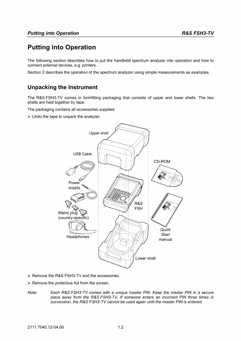
Unpacking the Instrument
The R&S FSH3-TV comes in formfitting packaging that consists of upper and lower shells. The two shells are held together by tape.
The packaging contains all accessories supplied.
Undo the tape to unpack the analyzer.
Upper shell
USB Cable
Powersupply
Mains plug(country-specific)
Headphones
Lower shell
CD-ROM
QuickStart
manual
R&SFSH
Remove the R&S FSH3-TV and the accessories.
Remove the protective foil from the screen.
Note: Each R&S FSH3-TV comes with a unique master PIN. Keep the master PIN in a secure place away from the R&S FSH3-TV. If someone enters an incorrect PIN three times in succession, the R&S FSH3-TV cannot be used again until the master PIN is entered.

R&S FSH3-TV Putting into Operation
2111.7040.12-04.00 1.3
Setting up the Instrument
The handheld TV Analyzer R&S FSH3-TV has been designed for operation in labs as well as for on-site use for service and maintenance applications.
For any application, the R&S FSH3-TV can be set up to optimize ease of operation and the viewing angle of the display. When used as a desktop instrument, the R&S FSH3-TV can either be laid flat or it can be propped up using the fold-out support at the back.
The R&S FSH3-TV can be laid flat for operation from above. Because the grip is slightly raised at the back, the R&S FSH3-TV is tilted forward to give the optimum viewing angle for the display.
For use as a desktop, fold out the support at the rear so that the instrument can easily be operated from the front and the display can be read easily (see Fig.).
For on-site installation and service measurements, it is best to hold the instrument with both hands. All the controls are easy to reach (e.g. with your thumbs). Use the R&S FSH-Z25 carrying bag so that you have both hands free to adjust the DUT. The R&S FSH3-TV can be placed in the hanger provided on the open bag for this purpose.
To secure the instrument in place, affix its carrying handle to the front of the carrying bag with the Velcro tape.
The carrying handle at the top of the R&S FSH3-TV can also be used to hang it from cabinet doors, for example. The shape of the grip ensures that the instrument does not fall off.

Putting into Operation R&S FSH3-TV
2111.7040.12-04.00 1.4
Switching on the TV Analyzer
The R&S FSH3-TV can be powered using either the included power supply unit or internal battery. When fully charged, the built-in nickel metal hydride battery provides an operating time of three to four hours. On delivery, the battery in the R&S FSH3-TV may be flat. Therefore, it must be charged before the R&S FSH3-TV can be used. If the instrument is switched off, the charging time is about four hours. When the adapter is used, the R&S FSH3-TV’s battery is charged simultaneously. However, charging takes much longer if the R&S FSH3-TV is switched on. A battery that is almost flat should therefore be charged when the R&S FSH3-TV is off.
Insert the jack plug of the power supply unit into the POWER ADAPTER connector on the right-hand side of the carrying handle so that it locks into position. Then connect the power supply unit to an AC outlet. The voltage range of the power supply unit is 100 V to 240 V.
Caution! Only the supplied power supply unit – the R&S FSH-Z33 – may be used to power the R&S FSH3-TV or charge the battery from the AC supply.
Prior to use, make sure that the AC supply voltage is compatible with the voltage specified on the power supply unit. Before inserting the power supply unit into the AC power outlet, attach the appropriate adapter.
In vehicles, the battery can be charged from the cigarette lighter socket using the R&S FSH-Z21 cable.
Caution! It is strictly forbidden to operate the R&S FSH3-TV via the cigarette lighter socket while the vehicle is in motion or the engine is running. In these cases, the R&S FSH3-TV must be off.
While the battery of the R&S FSH3-TV is being charged via the 12 V Car Adapter R&S FSH-Z21, the car adapter must not be connected to the vehicle's ground (for example, via the RF connector) under any circumstances.
To switch on the R&S FSH3-TV, press the yellow button at the bottom left of the front panel. To indicate that it is connected to the AC supply, the R&S FSH3-TV displays a connector symbol in the middle of the display above the softkey labels.
When the R&S FSH3-TV is switched on, it recalls the settings that it was using when it was last switched off. Note: If the internal battery is completely flat, the R&S FSH3-TV cannot be switched on even
though it is connected to the AC supply via the power supply unit. In this case, the internal battery must be charged for a while with the instrument switched off. Only then can the instrument be switched on.
R&S FSH3-TV Putting into Operation
2111.7040.12-04.00 1.5
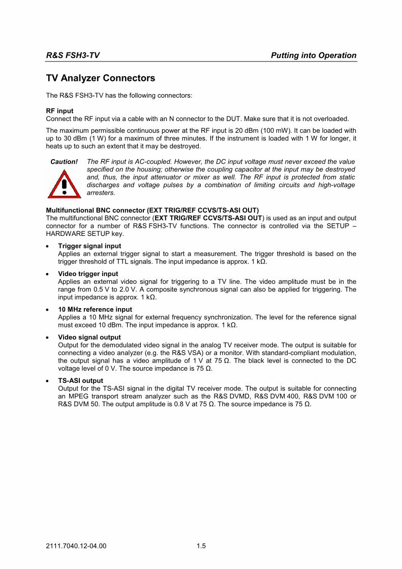
TV Analyzer Connectors
The R&S FSH3-TV has the following connectors: RF input Connect the RF input via a cable with an N connector to the DUT. Make sure that it is not overloaded.
The maximum permissible continuous power at the RF input is 20 dBm (100 mW). It can be loaded with up to 30 dBm (1 W) for a maximum of three minutes. If the instrument is loaded with 1 W for longer, it heats up to such an extent that it may be destroyed.
Caution! The RF input is AC-coupled. However, the DC input voltage must never exceed the value specified on the housing; otherwise the coupling capacitor at the input may be destroyed and, thus, the input attenuator or mixer as well. The RF input is protected from static discharges and voltage pulses by a combination of limiting circuits and high-voltage arresters.
Multifunctional BNC connector (EXT TRIG/REF CCVS/TS-ASI OUT) The multifunctional BNC connector (EXT TRIG/REF CCVS/TS-ASI OUT) is used as an input and output connector for a number of R&S FSH3-TV functions. The connector is controlled via the SETUP – HARDWARE SETUP key.
• Trigger signal input Applies an external trigger signal to start a measurement. The trigger threshold is based on the trigger threshold of TTL signals. The input impedance is approx. 1 kΩ.
• Video trigger input Applies an external video signal for triggering to a TV line. The video amplitude must be in the range from 0.5 V to 2.0 V. A composite synchronous signal can also be applied for triggering. The input impedance is approx. 1 kΩ.
• 10 MHz reference input Applies a 10 MHz signal for external frequency synchronization. The level for the reference signal must exceed 10 dBm. The input impedance is approx. 1 kΩ.
• Video signal output Output for the demodulated video signal in the analog TV receiver mode. The output is suitable for connecting a video analyzer (e.g. the R&S VSA) or a monitor. With standard-compliant modulation, the output signal has a video amplitude of 1 V at 75 Ω. The black level is connected to the DC voltage level of 0 V. The source impedance is 75 Ω.
• TS-ASI output Output for the TS-ASI signal in the digital TV receiver mode. The output is suitable for connecting an MPEG transport stream analyzer such as the R&S DVMD, R&S DVM 400, R&S DVM 100 or R&S DVM 50. The output amplitude is 0.8 V at 75 Ω. The source impedance is 75 Ω.
Putting into Operation R&S FSH3-TV
2111.7040.12-04.00 1.6
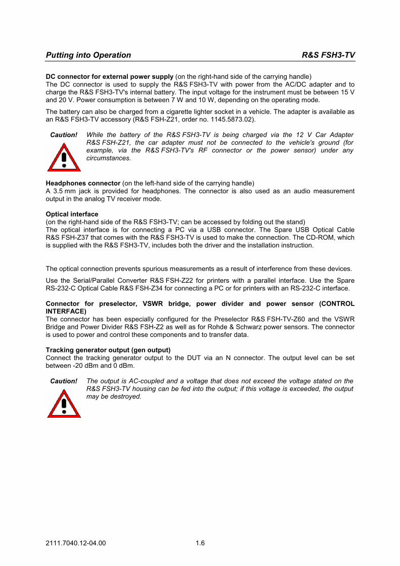
DC connector for external power supply (on the right-hand side of the carrying handle) The DC connector is used to supply the R&S FSH3-TV with power from the AC/DC adapter and to charge the R&S FSH3-TV's internal battery. The input voltage for the instrument must be between 15 V and 20 V. Power consumption is between 7 W and 10 W, depending on the operating mode.
The battery can also be charged from a cigarette lighter socket in a vehicle. The adapter is available as an R&S FSH3-TV accessory (R&S FSH-Z21, order no. 1145.5873.02).
Caution! While the battery of the R&S FSH3-TV is being charged via the 12 V Car Adapter R&S FSH-Z21, the car adapter must not be connected to the vehicle's ground (for example, via the R&S FSH3-TV's RF connector or the power sensor) under any circumstances.
Headphones connector (on the left-hand side of the carrying handle) A 3.5 mm jack is provided for headphones. The connector is also used as an audio measurement output in the analog TV receiver mode. Optical interface (on the right-hand side of the R&S FSH3-TV; can be accessed by folding out the stand) The optical interface is for connecting a PC via a USB connector. The Spare USB Optical Cable R&S FSH-Z37 that comes with the R&S FSH3-TV is used to make the connection. The CD-ROM, which is supplied with the R&S FSH3-TV, includes both the driver and the installation instruction.
The optical connection prevents spurious measurements as a result of interference from these devices.
Use the Serial/Parallel Converter R&S FSH-Z22 for printers with a parallel interface. Use the Spare RS-232-C Optical Cable R&S FSH-Z34 for connecting a PC or for printers with an RS-232-C interface. Connector for preselector, VSWR bridge, power divider and power sensor (CONTROL INTERFACE) The connector has been especially configured for the Preselector R&S FSH-TV-Z60 and the VSWR Bridge and Power Divider R&S FSH-Z2 as well as for Rohde & Schwarz power sensors. The connector is used to power and control these components and to transfer data. Tracking generator output (gen output) Connect the tracking generator output to the DUT via an N connector. The output level can be set between -20 dBm and 0 dBm.
Caution! The output is AC-coupled and a voltage that does not exceed the voltage stated on the R&S FSH3-TV housing can be fed into the output; if this voltage is exceeded, the output may be destroyed.

R&S FSH3-TV Putting into Operation
2111.7040.12-04.00 1.7
Screen Settings
The R&S FSH3-TV’s screen is a transflective, passive color LCD. Indoors, its brightness depends on the intensity of the backlighting. If light irradiation is strong, the ambient light supports readability. The viewing angle can be optimized by adjusting the contrast. To achieve maximum contrast, the screen can be switched from color display to black-and-white display.
To strike a balance between battery operating time and screen display quality, set backlighting to the minimum brightness needed.
Setting brightness Press the SETUP key.
Press the DISPLAY softkey.
The submenu with the contrast, lighting and color settings opens. Using the rotary knob or cursor keys, select LIGHT...
and confirm by pressing the DISPLAY softkey or the ENTER key again.
The BACKLIGHT submenu for the lighting level opens. The level can be set to HIGH, NORMAL and LOW. Using the rotary knob or cursor keys, select the
setting you want and confirm by pressing the DISPLAY softkey or the ENTER key.
Setting the contrast Press the SETUP key.
Press the DISPLAY softkey.
The submenu with the contrast, lighting and color settings opens. Using the rotary knob or the cursor keys, select
CONTRAST... and confirm by pressing the DISPLAY softkey or the ENTER key again.
The contrast value entry box opens. Using the rotary knob, adjust the contrast until
screen legibility is optimal.
When setting the contrast, view the display at the same angle that will be used for the application. Confirm the entry with the ENTER key or by
pressing the DISPLAY softkey again.
The R&S FSH3-TV displays the setting in the Display Contrast line in the overview of the setup settings.

Putting into Operation R&S FSH3-TV
2111.7040.12-04.00 1.8
Setting the screen color Press the SETUP key.
Press the DISPLAY softkey.
The submenu with the contrast, lighting and color settings opens. Using the rotary knob or cursor keys, select TYPE...
and confirm with the ENTER key or by pressing the DISPLAY softkey again.
In the submenu that opens, select COLOR or BLACK/WHITE.
Confirm with the ENTER key or by pressing the DISPLAY softkey again.
The R&S FSH3-TV switches to the selected color settings.
R&S FSH3-TV Putting into Operation
2111.7040.12-04.00 1.9
Country-Specific Settings
The R&S FSH3-TV is “multilingual” and can display text in the language of your choice. The softkey lettering is always in English. The default setting (factory-setting) is also English.
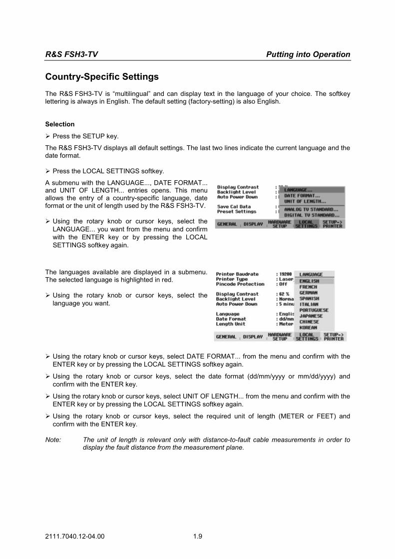
Selection Press the SETUP key.
The R&S FSH3-TV displays all default settings. The last two lines indicate the current language and the date format. Press the LOCAL SETTINGS softkey.
A submenu with the LANGUAGE..., DATE FORMAT... and UNIT OF LENGTH... entries opens. This menu allows the entry of a country-specific language, date format or the unit of length used by the R&S FSH3-TV. Using the rotary knob or cursor keys, select the
LANGUAGE... you want from the menu and confirm with the ENTER key or by pressing the LOCAL SETTINGS softkey again.
The languages available are displayed in a submenu. The selected language is highlighted in red. Using the rotary knob or cursor keys, select the
language you want.
Using the rotary knob or cursor keys, select DATE FORMAT... from the menu and confirm with the ENTER key or by pressing the LOCAL SETTINGS softkey again.
Using the rotary knob or cursor keys, select the date format (dd/mm/yyyy or mm/dd/yyyy) and confirm with the ENTER key.
Using the rotary knob or cursor keys, select UNIT OF LENGTH... from the menu and confirm with the ENTER key or by pressing the LOCAL SETTINGS softkey again.
Using the rotary knob or cursor keys, select the required unit of length (METER or FEET) and confirm with the ENTER key.
Note: The unit of length is relevant only with distance-to-fault cable measurements in order to display the fault distance from the measurement plane.

Putting into Operation R&S FSH3-TV
2111.7040.12-04.00 1.10
Setting the Date and Time
The R&S FSH3-TV has an internal clock that can apply a date and time stamp, e.g. for output to a printer or stored data records. The user can reset the date and time.
Setting the date
Press the SETUP key.
Press the GENERAL softkey.
Using the rotary knob or cursor keys, select DATE... from the menu and confirm with the ENTER key.
The value entry box above the row of softkey labels is highlighted in red and displays the currently set date in the selected format (dd/mm/yyyy or mm/dd/yyyy). The active value entry field is highlighted in white.
Depending on the date format, change the day (dd) or month (mm) by using the rotary knob, cursor keys or a numeric entry and confirm with the ENTER key.
After the entry, the cursor automatically moves to the second field in the date (day or month, depending on the date format). Proceed with the next two fields as with the first. After the last data block has been entered, the R&S FSH3-TV verifies the validity of the entered date. If the date is not valid, the R&S FSH3-TV sets the next valid date.
Setting the time
Press the SETUP key.
Press the GENERAL softkey.
Using the rotary knob or cursor keys, select TIME... from the menu and confirm with the ENTER key.
The value entry box above the row of softkey labels is highlighted in red and displays the currently set time in hours:minutes format. The hours display is highlighted in white to enter a new value.
Change the hours with the rotary knob, cursor keys or numeric entry and confirm with the ENTER key.
After entry, the cursor automatically goes to the minutes display. The entry is the same as for the hours display.
After the minutes have been entered, the R&S FSH3-TV verifies the validity of the entered time. If the time is not valid, the R&S FSH3-TV sets the next valid time.
R&S FSH3-TV Charging the Battery
2111.7040.12-04.00 1.11
Charging the Battery
The R&S FSH3-TV is fitted with a nickel metal hydride battery. The operating time is three to four hours at room temperature if the battery is fully charged.
Note: The battery in the R&S FSH3-TV is not charged when it leaves the factory. It must therefore be charged after delivery.
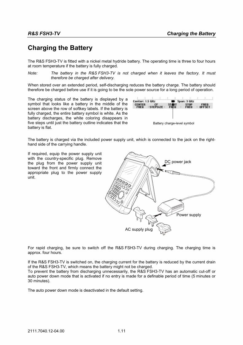
When stored over an extended period, self-discharging reduces the battery charge. The battery should therefore be charged before use if it is going to be the sole power source for a long period of operation. The charging status of the battery is displayed by a symbol that looks like a battery in the middle of the screen above the row of softkey labels. If the battery is fully charged, the entire battery symbol is white. As the battery discharges, the white coloring disappears in five steps until just the battery outline indicates that the battery is flat.
Battery charge-level symbol
The battery is charged via the included power supply unit, which is connected to the jack on the right-hand side of the carrying handle. If required, equip the power supply unit with the country-specific plug. Remove the plug from the power supply unit toward the front and firmly connect the appropriate plug to the power supply unit.
AC supply plug
Power supply
DC power jack
For rapid charging, be sure to switch off the R&S FSH3-TV during charging. The charging time is approx. four hours. If the R&S FSH3-TV is switched on, the charging current for the battery is reduced by the current drain of the R&S FSH3-TV, which means the battery might not be charged. To prevent the battery from discharging unnecessarily, the R&S FSH3-TV has an automatic cut-off or auto power down mode that is activated if no entry is made for a definable period of time (5 minutes or 30 minutes). The auto power down mode is deactivated in the default setting.
Selecting the Instrument Default Setup R&S FSH3-TV
2111.7040.12-04.00 1.12
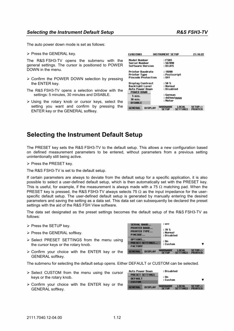
The auto power down mode is set as follows: Press the GENERAL key.
The R&S FSH3-TV opens the submenu with the general settings. The cursor is positioned to POWER DOWN in the menu. Confirm the POWER DOWN selection by pressing
the ENTER key.
The R&S FSH3-TV opens a selection window with the settings: 5 minutes, 30 minutes and DISABLE.
Using the rotary knob or cursor keys, select the setting you want and confirm by pressing the ENTER key or the GENERAL softkey.
Selecting the Instrument Default Setup
The PRESET key sets the R&S FSH3-TV to the default setup. This allows a new configuration based on defined measurement parameters to be entered, without parameters from a previous setting unintentionally still being active.
Press the PRESET key.
The R&S FSH3-TV is set to the default setup.
If certain parameters are always to deviate from the default setup for a specific application, it is also possible to select a user-defined default setup, which is then automatically set with the PRESET key. This is useful, for example, if the measurement is always made with a 75 Ω matching pad. When the PRESET key is pressed, the R&S FSH3-TV always selects 75 Ω as the input impedance for the user-specific default setup. The user-defined default setup is generated by manually entering the desired parameters and saving the setting as a data set. This data set can subsequently be declared the preset settings with the aid of the R&S FSH View software.
The data set designated as the preset settings becomes the default setup of the R&S FSH3-TV as follows: Press the SETUP key.
Press the GENERAL softkey.
Select PRESET SETTINGS from the menu using the cursor keys or the rotary knob.
Confirm your choice with the ENTER key or the GENERAL softkey.
The submenu for selecting the default setup opens. Either DEFAULT or CUSTOM can be selected. Select CUSTOM from the menu using the cursor
keys or the rotary knob.
Confirm your choice with the ENTER key or the GENERAL softkey.

R&S FSH3-TV Multifunctional BNC Connector Control
2111.7040.12-04.00 1.13
The parameters defined in the data set for the default setup are now used as the preset settings. If no user-specific default setup is defined, CUSTOM is inactive and cannot be selected. The data set defined as the user default setup can be viewed using the R&S FSH3-TV's recall function. Press the SAVE/PRINT key.
Press the RECALL softkey.
All stored data sets are displayed. The status of the data set is indicated in the status field: P: Preset setting
: Data set disabled If no data sets are stored in the R&S FSH3-TV, the message "No datasets available" is output instead of the list of data sets.
User-defineddefault setup
Data set notoverwritable ordeletable
Data setoverwritable
Status field
Multifunctional BNC Connector Control
The EXT TRIG/REF CCVS/TS-ASI OUT BNC connector on the top of the R&S FSH3-TV can be used as an input and output connector for a number of instrument functions.
• Trigger signal input Applies an external trigger signal to start a measurement.
• Video trigger input Applies an external video signal for triggering to a TV line.
• 10 MHz reference input Applies a 10 MHz signal for external frequency synchronization.
• Video signal output Output for the demodulated video signal in the analog TV receiver mode.
• TS-ASI output Output for the TS-ASI signal in the digital TV receiver mode.
Control is via the SETUP menu. Press the SETUP key. Press the HARDWARE SETUP softkey.
Using the rotary knob or cursor keys, select BNC I/O MODE... and confirm with the ENTER key or the HARDWARE SETUP softkey.
The active setting for the multifunctional BNC connector is highlighted in green.
Using the rotary knob or the cursor keys, select TS-ASI OUT, CCVS OUT, EXT REF or EXT TRIG.
Controlling the RF Attenuator R&S FSH3-TV
2111.7040.12-04.00 1.14
Confirm your selection with the ENTER key or the HARDWARE SETUP softkey.
The EXT TRIG setting is only for input configuration. The use of the external trigger must be set in the SWEEP menu (SWEEP key, TRIGGER softkey). The TS-ASI OUT setting can only be selected in digital TV receiver mode. The CCVS OUT setting can only be selected in analog TV receiver mode. The input setting can be queried via the status display (press the STATUS key).
Controlling the RF Attenuator
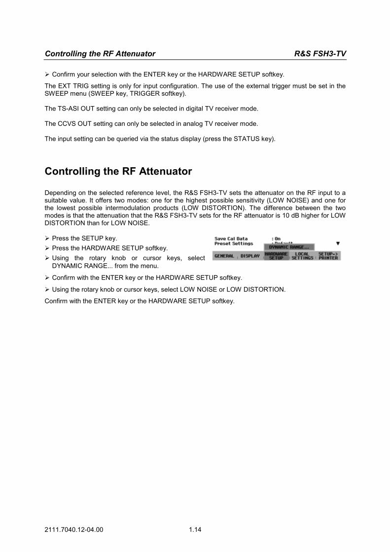
Depending on the selected reference level, the R&S FSH3-TV sets the attenuator on the RF input to a suitable value. It offers two modes: one for the highest possible sensitivity (LOW NOISE) and one for the lowest possible intermodulation products (LOW DISTORTION). The difference between the two modes is that the attenuation that the R&S FSH3-TV sets for the RF attenuator is 10 dB higher for LOW DISTORTION than for LOW NOISE. Press the SETUP key. Press the HARDWARE SETUP softkey. Using the rotary knob or cursor keys, select
DYNAMIC RANGE... from the menu.
Confirm with the ENTER key or the HARDWARE SETUP softkey.
Using the rotary knob or cursor keys, select LOW NOISE or LOW DISTORTION.
Confirm with the ENTER key or the HARDWARE SETUP softkey.

R&S FSH3-TV Using a Preamplifier
2111.7040.12-04.00 1.15
Using a Preamplifier
The R&S FSH3-TV comes with an internal preamplifier for increasing sensitivity. Depending on the frequency, this amplifier has 15 dB to 18 dB gain and increases sensitivity by 10 to 15 dB. It is fitted behind the RF attenuator and in front of the input mixer. Press the SETUP key.
Press the HARDWARE SETUP softkey.
Using the rotary knob or cursor keys, select PREAMP... .
Confirm with the ENTER key or the HARDWARE SETUP softkey.
The R&S FSH3-TV changes to the submenu for preamplifier configuration. The selection bar indicates the active setting. Using the rotary knob or cursor keys, select the
setting you want (ON or OFF) and confirm by pressing the ENTER key.
If the preamplifier is switched on, its use is coupled to the reference level, thus ensuring the optimum dynamic range of the R&S FSH3-TV at all times. The table below shows the positions of the RF attenuator and the preamplifier as a function of the reference level.
Preamplifier OFF
Preamplifier ON Ref Level
RF attenuation RF attenuation PreamplifierLow noise Low distortion Low noise Low distortion
≤–25 dBm 0 dB 0 dB 0 dB 0 dB On
-24 dBm to –20 dBm 0 dB 0 dB 10 dB 10 dB On
-19 dBm to –15 dBm 0 dB 10 dB 10 dB 10 dB On
-14 dBm to –10 dBm 0 dB 10 dB 0 dB 10 dB Off
-9 dBm to 0 dBm 10 dB 20 dB 10 dB 20 dB Off
1 dBm to 10 dBm 20 dB 30 dB 20 dB 30 dB Off
11 dBm to 20 dBm 30 dB 30 dB 30 dB 30 dB Off
The attenuator position can be queried at any time via the status display.
PIN Entry R&S FSH3-TV
2111.7040.12-04.00 1.16
PIN Entry
To prevent unauthorized use, the R&S FSH3-TV can be protected with a personal identification number (PIN).
When the R&S FSH3-TV is delivered, the PIN is set to 0000 and PIN entry is disabled when the R&S FSH3-TV is switched on. A PIN, i.e. a four-digit number, can be re-entered whenever you wish. But it is not activated until the PIN mode has been enabled. A new PIN is entered as follows:
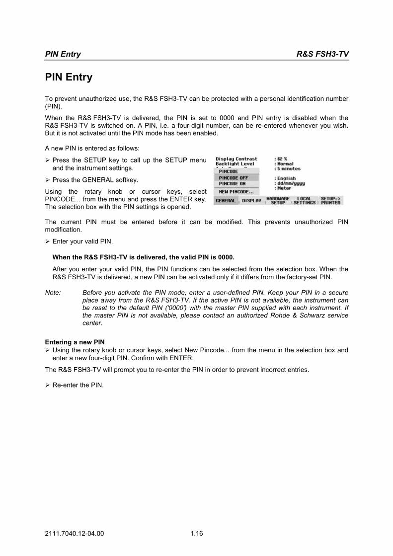
Press the SETUP key to call up the SETUP menu and the instrument settings.
Press the GENERAL softkey.
Using the rotary knob or cursor keys, select PINCODE... from the menu and press the ENTER key. The selection box with the PIN settings is opened. The current PIN must be entered before it can be modified. This prevents unauthorized PIN modification.
Enter your valid PIN. When the R&S FSH3-TV is delivered, the valid PIN is 0000.
After you enter your valid PIN, the PIN functions can be selected from the selection box. When the R&S FSH3-TV is delivered, a new PIN can be activated only if it differs from the factory-set PIN.
Note: Before you activate the PIN mode, enter a user-defined PIN. Keep your PIN in a secure place away from the R&S FSH3-TV. If the active PIN is not available, the instrument can be reset to the default PIN ('0000') with the master PIN supplied with each instrument. If the master PIN is not available, please contact an authorized Rohde & Schwarz service center.
Entering a new PIN Using the rotary knob or cursor keys, select New Pincode... from the menu in the selection box and
enter a new four-digit PIN. Confirm with ENTER.
The R&S FSH3-TV will prompt you to re-enter the PIN in order to prevent incorrect entries. Re-enter the PIN.
R&S FSH3-TV PIN Entry
2111.7040.12-04.00 1.17
Activating the PIN mode Using the rotary knob or cursor keys, select PINCODE ON from the menu and press the ENTER key.
The R&S FSH3-TV now prompts you to enter the PIN prior to its activation. Enter the PIN and confirm with the ENTER key.
The selected PIN is now activated. The next time you switch on the R&S FSH3-TV, you must enter the PIN before you can operate the instrument. If you enter an incorrect PIN , the R&S FSH3-TV again prompts you for the PIN code. After three attempts with an incorrect PIN, the R&S FSH3-TV prompts you for the master PIN.
Note: The R&S FSH3-TV comes with labels reading ‘PIN Code protected’. If the instrument is protected with a PIN, affix one of these labels to the instrument. This warns unauthorized users that they cannot operate the R&S FSH3-TV.
Deactivating PIN protection Using the rotary knob or cursor keys, select PINCODE OFF from the menu and press the ENTER
key.
Prior to deactivation, the R&S FSH3-TV prompts you to enter your PIN. This prevents unauthorized deactivation of PIN protection. Enter your PIN number and confirm with the ENTER key.
The R&S FSH3-TV can now be operated without PIN protection.

Connecting a Printer R&S FSH3-TV
2111.7040.12-04.00 1.18
Connecting a Printer
The R&S FSH3-TV can output a screenshot to a connected printer. The Serial/Parallel Converter R&S FSH-Z22 is available as an accessory for printers with a parallel interface. The Spare RS-232-C Optical Cable R&S FSH-Z34 is available as an accessory for printers with an RS-232-C interface.
A printer with an RS-232-C interface can be directly connected using the RS-232-C optical interface cable that is supplied. Fold out the stand at the rear of the
R&S FSH3-TV. Connect the optical connector of the
RS-232-C cable to the optical interface on the right-hand side of the R&S FSH3-TV.
Connect the RS-232-C connector of the cable to the printer.
Optical RS-232-Cinterface
RS-232-C cable
9-pinconnector
Connect printers with a parallel interface to the R&S FSH3-TV using the Serial/Parallel Converter R&S FSH-Z22, thus freeing up the Centronics parallel interface to connect a printer. The R&S FSH-Z22 is powered by a 9 V alkaline battery (NEDA, IEC6LR61). Fold out the stand at the rear of the
R&S FSH3-TV. Connect the optical connector of the
R&S FSH-Z22 to the optical interface on the right-hand side of the R&S FSH3-TV.
Connect the printer cable to the 25-pin interface of the R&S FSH-Z22.
Switch on the serial/parallel converter using the slide switch on its top.
Slide switch positions:
OFF The R&S FSH-Z22 is off. ON The R&S FSH-Z22 is on, and
the Battery OK LED flashes. AUTO OFF The R&S FSH-Z22 is on, and
the Battery OK LED flashes. If data transmission is interrup-ted for more than 5 minutes, the R&S FSH-Z22 is switched off automatically.
Optical RS-232-Cinterface
R&SFSH-Z22

R&S FSH3-TV Connecting a Printer
2111.7040.12-04.00 1.19
While data is being transmitted to the printer, the "Busy" LED remains lit.
Note: The R&S FSH-Z22 is designed for a data transmission rate of max. 38 400 baud (= default setting). Therefore, set the baud rate (PRINTER BAUD RATE) in the SETUP menu to 38 400 baud. The baud rates 9600 baud and 19 200 baud can also be set on the R&S FSH-Z22 by opening its housing.
Selecting a printer Press the SETUP key on the R&S FSH3-TV.
The R&S FSH3-TV displays the selected printer and its baud rate in the setup settings. To select another printer, proceed as follows: Press the GENERAL softkey.
Using the rotary knob or cursor keys, select PRINTER TYPE... from the menu and confirm with the ENTER key or by pressing the GENERAL softkey again.
Using the rotary knob or cursor keys, select the
printer you want and confirm with the ENTER key or by pressing the GENERAL softkey again.
The R&S FSH3-TV displays the selected printer under "Printer Type".
Next, set the baud rate for the selected printer. Press the GENERAL softkey.
Using the rotary knob or cursor keys, select PRINTER BAUD... from the menu and confirm with the ENTER key.
The selection box for the available baud rates (1200 baud to 115 200 baud) opens. Using the rotary knob or cursor keys, select the
baud rate you want and confirm with the ENTER key or by pressing the GENERAL softkey a second time.
The R&S FSH3-TV displays the selected baud rate under "RS232 Baudrate" in the setup display.
Note: If the serial/parallel converter (R&S FSH-Z22) is used to control a printer with a parallel interface, set the RS-232-C interface to 38 400 baud.
The contents of the setup display can be output to the printer by pressing the SETUP -> PRINTER softkey.

Setting the Baud Rate for Remote Control R&S FSH3-TV
2111.7040.12-04.00 1.20
Setting the Baud Rate for Remote Control
The R&S FSH3-TV offers different baud rates for remote control. The desired baud rate is set via the SETUP menu. Press the SETUP key.
Press the GENERAL softkey.
Use the rotary knob or the cursor keys to select SERIAL BAUD... from the menu and confirm the selection with the ENTER key.
The selection box for the available baud rates (9600 baud to 115200 baud) opens.
Use the rotary knob or the cursor keys to select the baud rate you want and confirm the entry with the ENTER key or by pressing the GENERAL softkey again.
The R&S FSH3-TV displays the selected baud rate under SERIAL BAUDRATE in the setup display.
Enabling Options
The R&S FSH3-TV can be fitted with options (e.g. distance-to-fault measurements on cables) which are enabled by entering a key code. The key code is based on the unique serial number of the instrument. To add an option, enable it with a key code.
Operation Press the SETUP key.
Press the GENERAL key.
Using the rotary knob or cursor keys, select OPTIONS... from the menu and confirm with the ENTER key.
Enter the key code (ten-digit number) for the option with the numeric keys and confirm with the ENTER key. If the correct key code is entered, the R&S FSH3-TV displays "<....> Option enabled". If an invalid key code is entered, the R&S FSH3-TV displays "Option key error". The correct key code can then be entered.

R&S FSH3-TV Checking the Installed Options
2111.7040.12-04.00 1.21
Checking the Installed Options
The R&S FSH3-TV displays the installed options in the SETUP menu so you can check them: Press the SETUP key.
Using the rotary knob or the cursor keys, scroll the status display downwards.
The R&S FSH3-TV displays all available options together with their current status.
R&S FSH3-TV Measurements with the Spectrum Analyzer
2111.7040.12-04.00 2.1
2 Getting Started
This section explains the basic operation of the handheld TV Analyzer R&S FSH3-TV.
Measurements with the Spectrum Analyzer
Sinewave Signal Measurement
A basic task performed by spectrum analyzers is measuring the level and frequency of sinewave signals. The following examples illustrate the most effective way of performing these measurements with the handheld TV Analyzer R&S FSH3-TV.
A signal generator is used as a signal source, e.g. the Signal Generator R&S SML.
Measurement setup:
Connect the RF output of the signal generator to the RF input of the R&S FSH3-TV. Signal generator settings:
Frequency 100 MHz Level -30 dBm
Level Measurement
First, set the R&S FSH3-TV to its default settings to show all the operating steps that are required.
Press the PRESET key.
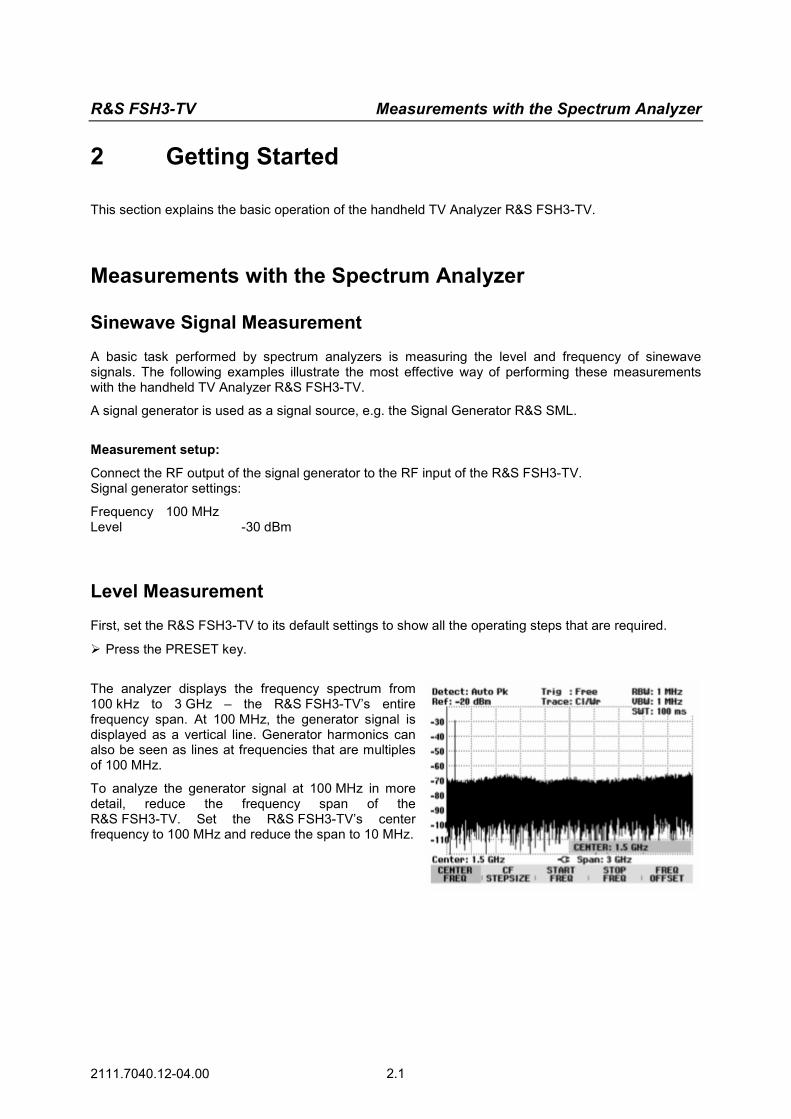
The analyzer displays the frequency spectrum from 100 kHz to 3 GHz – the R&S FSH3-TV’s entire frequency span. At 100 MHz, the generator signal is displayed as a vertical line. Generator harmonics can also be seen as lines at frequencies that are multiples of 100 MHz.
To analyze the generator signal at 100 MHz in more detail, reduce the frequency span of the R&S FSH3-TV. Set the R&S FSH3-TV’s center frequency to 100 MHz and reduce the span to 10 MHz.
Measurements with the Spectrum Analyzer R&S FSH3-TV
2111.7040.12-04.00 2.2
Press the FREQ key.
Enter “100” using the numeric keypad and confirm the entry with the MHz key.
Press the SPAN key.
Enter “10” using the numeric keypad and confirm the entry with the MHz key.
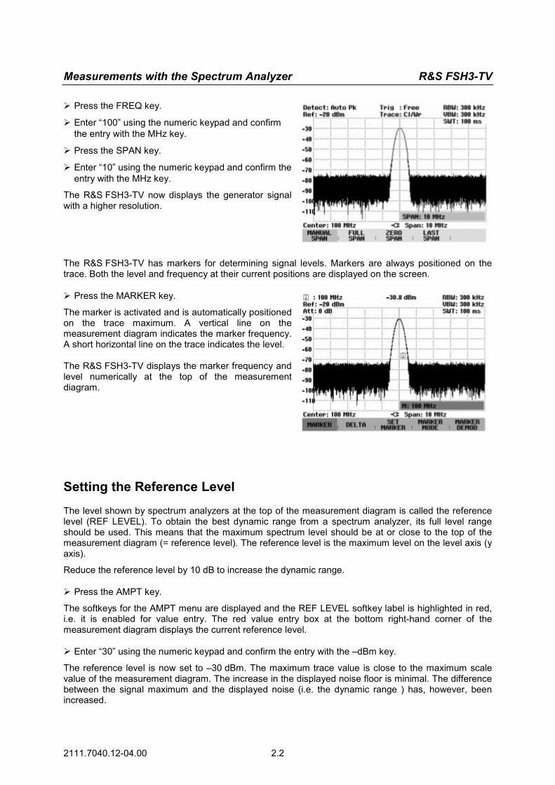
The R&S FSH3-TV now displays the generator signal with a higher resolution.
The R&S FSH3-TV has markers for determining signal levels. Markers are always positioned on the trace. Both the level and frequency at their current positions are displayed on the screen. Press the MARKER key.
The marker is activated and is automatically positioned on the trace maximum. A vertical line on the measurement diagram indicates the marker frequency. A short horizontal line on the trace indicates the level. The R&S FSH3-TV displays the marker frequency and level numerically at the top of the measurement diagram.
Setting the Reference Level
The level shown by spectrum analyzers at the top of the measurement diagram is called the reference level (REF LEVEL). To obtain the best dynamic range from a spectrum analyzer, its full level range should be used. This means that the maximum spectrum level should be at or close to the top of the measurement diagram (= reference level). The reference level is the maximum level on the level axis (y axis).
Reduce the reference level by 10 dB to increase the dynamic range. Press the AMPT key.
The softkeys for the AMPT menu are displayed and the REF LEVEL softkey label is highlighted in red, i.e. it is enabled for value entry. The red value entry box at the bottom right-hand corner of the measurement diagram displays the current reference level. Enter “30” using the numeric keypad and confirm the entry with the –dBm key.
The reference level is now set to –30 dBm. The maximum trace value is close to the maximum scale value of the measurement diagram. The increase in the displayed noise floor is minimal. The difference between the signal maximum and the displayed noise (i.e. the dynamic range ) has, however, been increased.

R&S FSH3-TV Measurements with the Spectrum Analyzer
2111.7040.12-04.00 2.3
Using markers is also an effective way to shift the trace maximum so that it coincides with the top of the measurement diagram. If the marker is positioned on the trace maximum (as in the example), the reference level can be set to the marker level by entering the following keystrokes: Press the MARKER key.
Press the SET MARKER softkey.
Select REF LVL = MRK LVL in the submenu by using the rotary knob or the cursor keys.
Press the ENTER key.
The reference level is then set to the measured level indicated by the marker. Only a few keystrokes are needed to set the optimal reference level.
Frequency Measurements
The R&S FSH3-TV’s trace displays 301 measurement points (frequency points). The marker is always positioned on one of these measurement points. The R&S FSH3-TV calculates the marker frequency from the measurement-point frequency, and the center frequency and frequency span that have been set. The measurement point resolution and, consequently, the accuracy of the marker-frequency readout therefore depend on the frequency span that has been selected.
The R&S FSH3-TV has a frequency counter to increase the accuracy of the marker frequency readout, It stops the sweep at the marker position, counts the frequency and then continues the sweep.
The following measurement example is based on the previous example. Press the MARKER MODE softkey in the marker
menu.
The marker mode selection box opens. Select FREQ COUNT from the selection box using
the rotary knob or the cursor keys.
Press the ENTER key.
The label 'M' at the upper left-hand corner of the measurement diagram changes to 'C' to tell you that the frequency counter has been switched on. The resolution of the frequency readout is now 1 Hz no matter what span has been set. The accuracy is determined by the R&S FSH3-TV’s internal reference frequency. It is far higher than that of pixel-oriented, marker-frequency readout.

Measurements with the Spectrum Analyzer R&S FSH3-TV
2111.7040.12-04.00 2.4
Harmonic Measurements of a Sinewave Signal
Since a spectrum analyzer can resolve different signals in the frequency domain, it is ideal for measuring harmonic levels or harmonic ratios. To speed up these operations, the R&S FSH3-TV has marker functions that deliver fast results with only a few keystrokes.
As above, a signal generator with a 100 MHz output frequency and an output level of –20 dBm is used in the following measurement example.
First, the R&S FSH3-TV is set to its default settings to show all measurement steps that are needed. Press the PRESET key.
The analyzer displays the frequency spectrum from 100 kHz to 3 GHz – the R&S FSH3-TV’s entire frequency span. At 100 MHz, the generator signal is displayed as a line. The generator harmonics are displayed as lines at frequencies that are multiples of 100 MHz.
To measure the second harmonic ratio, set the start and stop frequency as follows: Press the FREQ key.
The softkey menu opens entering the frequency. Press the START softkey.
Enter '50' using the numeric keypad and confirm the entry with the MHz key.
Press the STOP softkey.
Enter '250' using the numeric keypad and confirm the entry with the MHz key.
The R&S FSH3-TV now displays the spectrum from 50 MHz to 250 MHz and thus the signal at 100 MHz and its second harmonic at 200 MHz.
To measure the harmonic ratio, set the marker on the fundamental and the delta marker on the second harmonic. Press the MARKER key.
The softkey menu opens for marker entry and automatically positions the main marker on the trace maximum. Press the DELTA softkey.
The delta marker is activated (vertical dotted line) and is automatically placed on the next trace maximum (= second harmonic). The harmonic ratio in dB can be read directly from the numeric delta-marker display.
R&S FSH3-TV Measurements on Analog TV Signals
2111.7040.12-04.00 2.5
Measurements on Analog TV Signals
Measuring the Video-Signal-to-Noise Ratio
One of the main transmission parameters is the signal-to-noise ratio of the transmitted video signal. The following measurement example shows the individual steps used to effectively perform this measurement with the R&S FSH3-TV. An analog TV test transmitter such as the TV Test Transmitter R&S SFM is used as a signal source together with the CCVS + Component Generator R&S SAF.
Measurement setup:
Connect the R&S SAF video output to the R&S SFM video input, and the RF output of the analog TV test transmitter to the R&S FSH3-TV RF input.
Settings on the video signal generator:
Standard PAL, 625 lines CCIR 17 line 17 CCIR 330 line 330 Settings on the analog TV test transmitter:
Standard B/G, FM-IRT-A2 dual-channel sound Group delay general Frequency 210.25 MHz Level –17 dBm Set the R&S FSH3-TV to its default settings to show all the operating steps that are required.
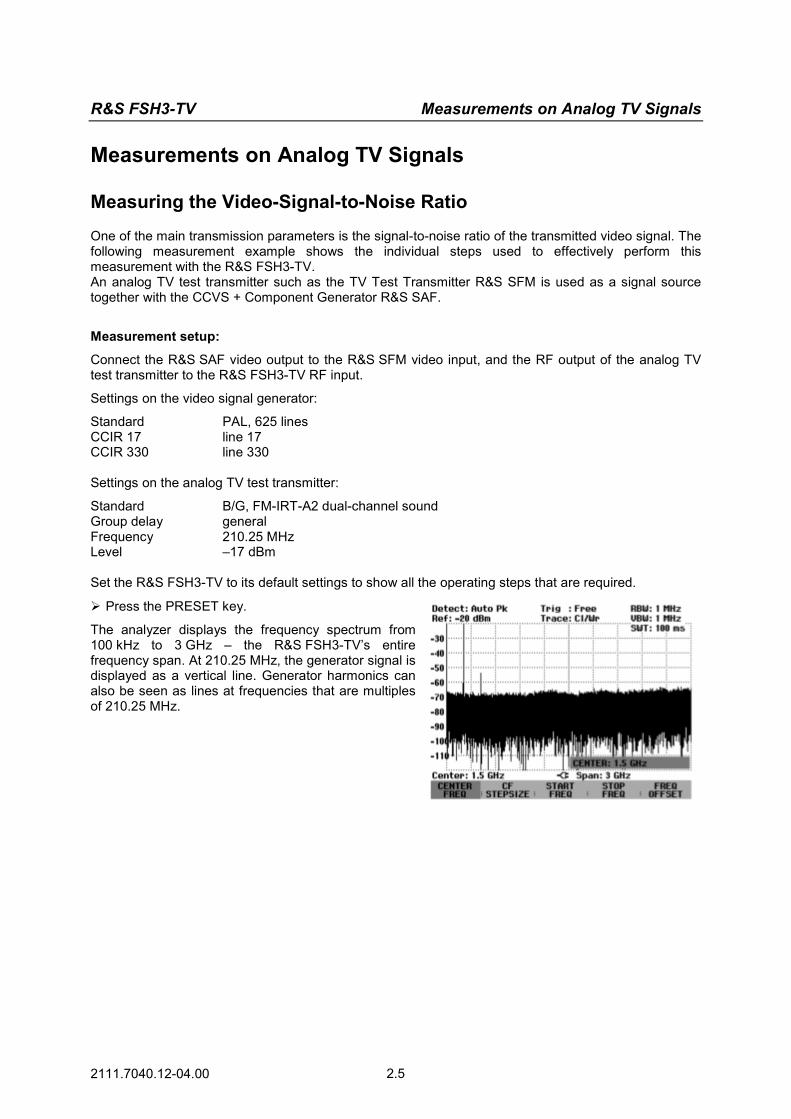
Press the PRESET key.
The analyzer displays the frequency spectrum from 100 kHz to 3 GHz – the R&S FSH3-TV’s entire frequency span. At 210.25 MHz, the generator signal is displayed as a vertical line. Generator harmonics can also be seen as lines at frequencies that are multiples of 210.25 MHz.
Measurements on Analog TV Signals R&S FSH3-TV
2111.7040.12-04.00 2.6
Activating the analog TV receiver:
Activate the ANALOG TV RECEIVER measurement to measure the signal-to-noise ratio.
Press the MEAS key.
Press the MEASURE softkey.
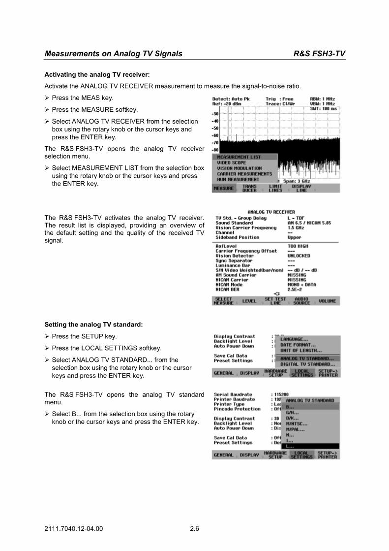
Select ANALOG TV RECEIVER from the selection box using the rotary knob or the cursor keys and press the ENTER key.
The R&S FSH3-TV opens the analog TV receiver selection menu.
Select MEASUREMENT LIST from the selection box using the rotary knob or the cursor keys and press the ENTER key.
The R&S FSH3-TV activates the analog TV receiver. The result list is displayed, providing an overview of the default setting and the quality of the received TV signal.
Setting the analog TV standard:
Press the SETUP key.
Press the LOCAL SETTINGS softkey.
Select ANALOG TV STANDARD... from the selection box using the rotary knob or the cursor keys and press the ENTER key.
The R&S FSH3-TV opens the analog TV standard menu.
Select B... from the selection box using the rotary knob or the cursor keys and press the ENTER key.

R&S FSH3-TV Measurements on Analog TV Signals
2111.7040.12-04.00 2.7
The R&S FSH3-TV opens the menu for setting the country-specific group delay precorrection.
Select GENERAL... from the selection box using the rotary knob or the cursor keys and press the ENTER key.
The R&S FSH3-TV opens the menu for setting the sound transmission standard.
Select FM 5.5 / FM 5.742... from the selection box using the rotary knob or the cursor keys and press the ENTER key.
The R&S FSH3-TV adjusts the analog TV receiver to the B standard using the GENERAL group delay precorrection and the FM sound transmission method in accordance with IRT A2.
Setting the receive frequency:
Press the FREQ key.
The R&S FSH3-TV opens the entry field for setting the vision carrier frequency.
Using the numeric keypad, enter 210.25 and confirm the entry with the MHz key.
The R&S FSH3-TV sets the receive frequency to a vision carrier frequency of 210.250000 MHz.
The measurement screen displays the main status settings and provides an overview of the analog TV signal received.
Setting the Quiet Line test line:
The R&S FSH3-TV measures the noise power of the demodulated video signal in the Quiet Line.
Press the MEAS key.
Press the SET TEST LINE softkey.
Select QUIET LINE from the selection box using the rotary knob or the cursor keys and press the ENTER key.
The R&S FSH3-TV opens the entry field for TV lines.
Using the numeric keypad, enter 6 and confirm the entry with the ENTER key.
Measurements on Analog TV Signals R&S FSH3-TV
2111.7040.12-04.00 2.8
Setting the RF attenuator:
Depending on the selected reference level, the R&S FSH3-TV provides the attenuator at the RF input. It offers two modes, the LOW NOISE mode for maximum sensitivity and the LOW DISTORTION mode for the lowest possible intermodulation products. The two modes differ in that the R&S FSH3-TV sets an RF attenuator attenuation that is 10 dB higher for LOW DISTORTION than it is for LOW NOISE.
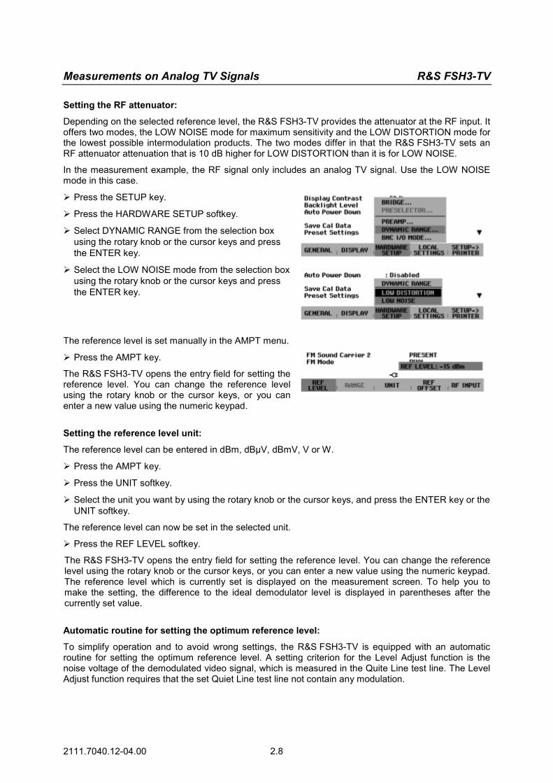
In the measurement example, the RF signal only includes an analog TV signal. Use the LOW NOISE mode in this case.
Press the SETUP key.
Press the HARDWARE SETUP softkey.
Select DYNAMIC RANGE from the selection box using the rotary knob or the cursor keys and press the ENTER key.
Select the LOW NOISE mode from the selection box using the rotary knob or the cursor keys and press the ENTER key.
The reference level is set manually in the AMPT menu.
Press the AMPT key.
The R&S FSH3-TV opens the entry field for setting the reference level. You can change the reference level using the rotary knob or the cursor keys, or you can enter a new value using the numeric keypad.
Setting the reference level unit:
The reference level can be entered in dBm, dBµV, dBmV, V or W.
Press the AMPT key.
Press the UNIT softkey.
Select the unit you want by using the rotary knob or the cursor keys, and press the ENTER key or the UNIT softkey.
The reference level can now be set in the selected unit.
Press the REF LEVEL softkey.
The R&S FSH3-TV opens the entry field for setting the reference level. You can change the reference level using the rotary knob or the cursor keys, or you can enter a new value using the numeric keypad. The reference level which is currently set is displayed on the measurement screen. To help you to make the setting, the difference to the ideal demodulator level is displayed in parentheses after the currently set value.
Automatic routine for setting the optimum reference level:
To simplify operation and to avoid wrong settings, the R&S FSH3-TV is equipped with an automatic routine for setting the optimum reference level. A setting criterion for the Level Adjust function is the noise voltage of the demodulated video signal, which is measured in the Quite Line test line. The Level Adjust function requires that the set Quiet Line test line not contain any modulation.

R&S FSH3-TV Measurements on Analog TV Signals
2111.7040.12-04.00 2.9
Press the MEAS key.
Press the LEVEL softkey.
Select LEVEL ADJUST from the selection box using the rotary knob or the cursor keys and press the ENTER key.
The R&S FSH3-TV sets the optimum reference level.
While the Level Adjust function is searching the optimum instrument setting, the screen displays this information as a message.
Video-signal-to-noise measurement parameter:
The R&S FSH3-TV measures the noise power in the Quiet Line, weights it in accordance with CCIR 567 and calculates its bar amplitude ratio. The R&S FSH3-TV displays two signal-to-noise ratio measurement parameters. It references the measured noise power to the nominal bar amplitude and to the measured bar amplitude. Both measurement values are displayed in the Measurement List screen.
With M/NTSC and M/PAL, the R&S FSH3-TV measures the bar amplitude either in the NTC7 COMP or FCC COMP test line; with all other standards, in the CCIR 17 test line.
To measure the bar amplitude correctly, the line number of the test line must correspond to the input signal.
In the measurement example, the CCIR 17 test line must correspond to line 17.
Press the MEAS key until the analog TV receiver main menu pops up.
Press the SET TEST LINE softkey.
Select CCIR 17 from the selection box using the rotary knob or the cursor keys and press the ENTER key.
The R&S FSH3-TV opens the entry field for TV lines.
Using the numeric keypad, enter 17 and confirm the entry with the ENTER key.

Measurements on Analog TV Signals R&S FSH3-TV
2111.7040.12-04.00 2.10
The signal-to-noise ratio weighted in accordance with CCIR 567 is displayed in the MEASUREMENT LIST screen.
The left measurement value is referenced to the measured bar amplitude, the right value to the nominal bar amplitude.

R&S FSH3-TV Measurements on Analog TV Signals
2111.7040.12-04.00 2.11
Measurements Using the Video Oscilloscope
The R&S FSH3-TV is equipped with a video oscilloscope, which displays the demodulated video signal on the measurement screen. The video oscilloscope can be triggered either by the demodulated video signal or by an external video signal. The R&S FSH3-TV provides marker functions to analyze trace values.
In the following measurement example, the video amplitude is measured in the CCIR 330 test line. The example explains the individual steps used to effectively perform this measurement with the R&S FSH3-TV. The operating steps are based on the settings of the "Measuring the Video-Signal-to-Noise Ratio" measurement example.
An analog TV test transmitter such as the TV Test Transmitter R&S SFM is used as a signal source together with the CCVS + Component Generator R&S SAF.
Measurement setup:
Connect the R&S SAF video output to the R&S SFM video input, and the RF output of the analog TV test transmitter to the R&S FSH3-TV RF input.
Settings on the video signal generator:
Standard PAL, 625 lines CCIR 17 line 17 CCIR 330 line 330 Settings on the analog TV test transmitter:
Standard B/G, FM-IRT-A2 dual-channel sound Group delay general Frequency 210.25 MHz Level –17 dBm
Activating the video oscilloscope:
Press the MEAS key until the ANALOG TV RECEIVER main menu pops up.
Press the SELECT MEASURE softkey.
Select VIDEO SCOPE from the selection box using the rotary knob or the cursor keys and press the ENTER key.
The measurement screen of the video oscilloscope is displayed. In the default setting, line 17 is displayed.
Setting the trigger:
Triggering occurs to a video line of the demodulated video signal.
Measurements on Analog TV Signals R&S FSH3-TV
2111.7040.12-04.00 2.12
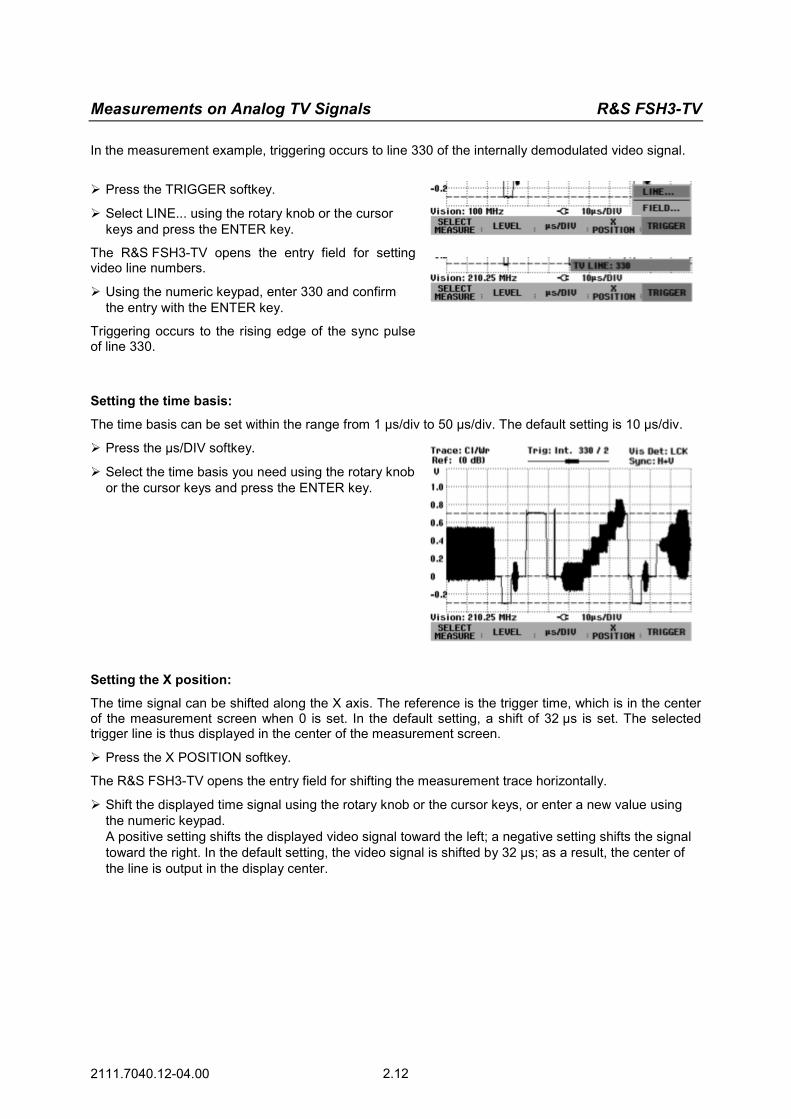
In the measurement example, triggering occurs to line 330 of the internally demodulated video signal.
Press the TRIGGER softkey.
Select LINE... using the rotary knob or the cursor keys and press the ENTER key.
The R&S FSH3-TV opens the entry field for setting video line numbers.
Using the numeric keypad, enter 330 and confirm the entry with the ENTER key.
Triggering occurs to the rising edge of the sync pulse of line 330.
Setting the time basis:
The time basis can be set within the range from 1 µs/div to 50 µs/div. The default setting is 10 µs/div.
Press the µs/DIV softkey.
Select the time basis you need using the rotary knob or the cursor keys and press the ENTER key.
Setting the X position:
The time signal can be shifted along the X axis. The reference is the trigger time, which is in the center of the measurement screen when 0 is set. In the default setting, a shift of 32 µs is set. The selected trigger line is thus displayed in the center of the measurement screen.
Press the X POSITION softkey.
The R&S FSH3-TV opens the entry field for shifting the measurement trace horizontally.
Shift the displayed time signal using the rotary knob or the cursor keys, or enter a new value using the numeric keypad. A positive setting shifts the displayed video signal toward the left; a negative setting shifts the signal toward the right. In the default setting, the video signal is shifted by 32 µs; as a result, the center of the line is output in the display center.

R&S FSH3-TV Measurements on Analog TV Signals
2111.7040.12-04.00 2.13
Setting the markers:
Using the markers, you can perform amplitude and time measurements.
Press the MARKER softkey.
Using the rotary knob, shift the marker approximately to the center of the white reference bar.
In the upper left corner of the measurement screen, the R&S FSH3-TV displays the amplitude of the white level referenced to the black level. An M precedes the measurement value.
Press the DELTA softkey.
Using the rotary knob, shift the delta marker approximately to the center of the sync pulse.
In the upper left corner of the measurement screen, the R&S FSH3-TV displays the amplitude of the video signal. The letter D precedes the measurement value.
Setting the trace averaging:
You can average the trace, which is advisable for noisy signals.
Press the TRACE key.
Press the TRACE MODE softkey.
Select AVERAGE from the selection box using the rotary knob or the cursor keys and press the ENTER key.
The R&S FSH3-TV opens the entry field for setting the averaging factor.
Using the numeric keypad, enter 10 and confirm the entry with the ENTER key.
The R&S FSH3-TV averages the last ten traces. The current and the selected averaging factor are displayed at the lower right of the measurement screen.

Measurements on Analog TV Signals R&S FSH3-TV
2111.7040.12-04.00 2.14
Measuring the Vision Carrier Modulation Depth
To determine the modulation depth or the residual carrier, the R&S FSH3-TV measures the power and the level of the vision carrier versus time and displays the result on the measurement screen.. The R&S FSH3-TV provides marker functions to analyze trace values.
In the following measurement example, the modulation depth is measured in the CCIR 330 test line. The example explains the individual steps used to effectively perform this measurement with the R&S FSH3-TV. The operating steps are based on the settings of the "Measuring the Video-Signal-to-Noise Ratio" measurement example. An analog TV test transmitter such as the TV Test Transmitter R&S SFM is used as a signal source together with the CCVS + Component Generator R&S SAF.
Note: The video output signal and the audio output signals are not available in the VISION MODULATION operating mode.
Measurement setup:
Connect the R&S SAF video output to the R&S SFM video input, and the RF output of the analog TV test transmitter to the R&S FSH3-TV RF input.
Settings on the video signal generator:
Standard PAL, 625 lines CCIR 17 line 17 CCIR 330 line 330 Settings on the analog TV test transmitter:
Standard B/G, FM-IRT-A2 dual-channel sound Group delay general Frequency 210.25 MHz Level –20 dBm
Activating the vision carrier modulation measurement:
Press the MEAS key until the ANALOG TV RECEIVER main menu pops up.
Press the SELECT MEASURE softkey.
Select VISION MODULATION from the selection box using the rotary knob or the cursor keys and press the ENTER key.
The measurement screen for determining the vision carrier modulation depth is displayed.
R&S FSH3-TV Measurements on Analog TV Signals
2111.7040.12-04.00 2.15
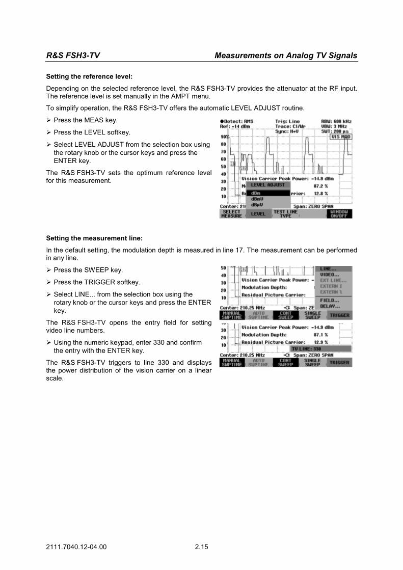
Setting the reference level:
Depending on the selected reference level, the R&S FSH3-TV provides the attenuator at the RF input. The reference level is set manually in the AMPT menu.
To simplify operation, the R&S FSH3-TV offers the automatic LEVEL ADJUST routine.
Press the MEAS key.
Press the LEVEL softkey.
Select LEVEL ADJUST from the selection box using the rotary knob or the cursor keys and press the ENTER key.
The R&S FSH3-TV sets the optimum reference level for this measurement.
Setting the measurement line:
In the default setting, the modulation depth is measured in line 17. The measurement can be performed in any line.
Press the SWEEP key.
Press the TRIGGER softkey.
Select LINE... from the selection box using the rotary knob or the cursor keys and press the ENTER key.
The R&S FSH3-TV opens the entry field for setting video line numbers.
Using the numeric keypad, enter 330 and confirm the entry with the ENTER key.
The R&S FSH3-TV triggers to line 330 and displays the power distribution of the vision carrier on a linear scale.

Measurements on Analog TV Signals R&S FSH3-TV
2111.7040.12-04.00 2.16
Setting the markers:
In the default setting, the marker positions match the test line type that is set in the Measurement List. The markers can be shifted to any position. Using RESET MARKERS, the markers are reset to the default position.
Press the MARKER key.
Press the SYNC MARKER softkey.
Using the rotary knob, shift the marker approximately to the center of the sync pulse.
Press the WHITE MARKER softkey.
Using the rotary knob, shift the marker approximately to the center of the white reference bar.
The R&S FSH3-TV displays the measured peak power, the modulation depth and the residual carrier of the vision carrier in the measurement screen.
Setting the trace averaging:
You can average the trace, which is advisable for noisy signals.
Press the TRACE key.
Press the TRACE MODE softkey.
Select AVERAGE from the selection box using the rotary knob or the cursor keys and press the ENTER key.
The R&S FSH3-TV opens the entry field for setting the averaging factor.
Using the numeric keypad, enter 10 and confirm the entry with the ENTER key.
The R&S FSH3-TV averages the last ten traces. The current and the selected averaging factor are displayed at the lower right of the measurement screen.
The measurement window conceals part of the trace. Using the WINDOW ON/OFF softkey in the MEAS menu, the measurement window can be blanked.

R&S FSH3-TV Measurements on Analog TV Signals
2111.7040.12-04.00 2.17
Measuring the Carrier Levels and Carrier Frequencies
Use the Carrier Measurements mode to determine the carrier levels and carrier frequencies of analog TV signals. The R&S FSH3-TV measures the vision carrier level, the vision carrier frequency offset, the vision carrier to sound carrier power ratios, the intercarrier frequencies of the AM/FM sound carriers, the FM deviation of the FM carriers and displays the measurement results in a parameter list.
In the following measurement example, a standard K analog TV signal with two FM sound carriers is measured. The example explains the individual steps used to effectively perform this measurement with the R&S FSH3-TV.
The operating steps described are based on the analyzer’s default setting.
An analog TV test transmitter such as the TV Test Transmitter R&S SFM is used as a signal source together with the CCVS + Component Generator R&S SAF.
Measurement setup:
Connect the R&S SAF video output to the R&S SFM video input, and the RF output of the analog TV test transmitter to the R&S FSH3-TV RF input.
Settings on the analog TV test transmitter:
Standard D/K, 1st FM sound carrier 6.500 MHz, 2nd FM sound carrier 6.258 MHz Group delay OIRT Frequency 210.25 MHz Level –20 dBm
Activating the Carrier Measurements mode of analog TV signals:
Press the MEAS key.
Press the MEASURE softkey.
Select ANALOG TV RECEIVER from the selection box using the rotary knob or the cursor keys and press the ENTER key.
The menu for selecting the analog TV measurement function opens. Select CARRIER MEASUREMENTS from the
selection box using the rotary knob or the cursor keys and press the ENTER key.
The measurement screen of the carrier levels and carrier frequencies is displayed.
Note: The video output signal and the audio output signals are not available in the CARRIER MEASUREMENTS operating mode.

Measurements on Analog TV Signals R&S FSH3-TV
2111.7040.12-04.00 2.18
Setting the analog TV standard:
Press the SETUP key.
Press the LOCAL SETTINGS softkey.
Select ANALOG TV STANDARD... from the selection box using the rotary knob or the cursor keys and press the ENTER key.
Select D/K... from the selection box using the rotary knob or the cursor keys and press the ENTER key.
Select OIRT... from the selection box using the rotary knob or the cursor keys and press the ENTER key.
Select FM 6.5/FM 6.258... from the selection box using the rotary knob or the cursor keys and press the ENTER key.
The R&S FSH3-TV adjusts the analog TV receiver to the D/K standard using the OIRT group delay precorrection and the FM sound transmission system in accordance with IRT A2 with the intercarrier frequencies 6.5 MHz for the first sound carrier, and 6.258 MHz for the second sound carrier.
Setting the receive frequency:
You can enter the channel center frequency, the vision carrier frequency or the channel number. In the measurement example, the vision carrier frequency is entered.
Press the FREQ key.
Press the VISION CARRIER softkey.
Using the numeric keypad, enter 210.25 and confirm the entry with the MHz key.
The R&S FSH3-TV sets the receive frequency to a vision carrier frequency of 210.25 MHz.
Setting the reference level:
The reference level can be set manually in the AMPT menu or automatically in the MEAS/LEVEL menu. The LEVEL ADJUST function is used in the measurement example.
Press the MEAS key.
Press the LEVEL softkey.
Select LEVEL ADJUST from the selection box using the rotary knob or the cursor keys and press the ENTER key.
The R&S FSH3-TV sets the optimum reference level for the carrier measurement.

R&S FSH3-TV Measurements on Analog TV Signals
2111.7040.12-04.00 2.19
Measurement screen containing the carrier levels and carrier frequencies:
The R&S FSH3-TV measures the level of the vision carrier and its frequency deviation from the set vision carrier frequency, the ratios of vision carrier level to sound carrier levels as well as the sound carrier frequencies referenced to the vision carrier. In addition to the measured values, the R&S FSH3-TV displays the most important settings on the measurement screen.
Measuring the Hum Modulation
To determine the hum modulation of analog TV signals, the R&S FSH3-TV provides the Hum Measurement mode. The R&S FSH3-TV calculates the hum modulation ratio in accordance with the EN 50083 standard. The R&S FSH3-TV must be tuned to the vision carrier. The vision carrier is filtered with a bandwidth of 600 kHz. This ensures that sound carriers and color subcarriers are suppressed and that the sync pulses are transmitted without any power degradation. The filtered vision carrier signal is sampled at the time of the sync pulse. As a result, the video information is removed from the measurement signal. The trace shows the sync pulse amplitude values of the vision carrier.
In the following measurement example, the hum modulation is measured. The example explains the individual steps used to effectively perform this measurement with the R&S FSH3-TV. The operating steps are based on the settings of the "Measuring the Video-Signal-to-Noise Ratio" measurement example.
An analog TV test transmitter such as the TV Test Transmitter R&S SFM is used as a signal source together with the CCVS + Component Generator R&S SAF. The video generator signal is superimposed by a 50 Hz hum signal.
Note: The video output signal and the audio output signals are not available in the HUM MEASUREMENT operating mode.
Activating the Hum Measurement mode:
Press the MEAS key until the ANALOG TV RECEIVER main menu pops up.
Press the SELECT MEASURE softkey.
Select HUM MEASUREMENT from the selection box using the rotary knob or the cursor keys and press the ENTER key.
The R&S FSH3-TV is set in accordance with the hum measurement.

Measurements on Analog TV Signals R&S FSH3-TV
2111.7040.12-04.00 2.20
Setting the reference level:
As a result of the hum modulation, the trace may be above the upper edge of the measurement screen. In this case, shift the trace by means of the reference level setting. The R&S FSH3-TV provides an automatic routine to simplify this procedure.
Press the MEAS key until the hum modulation menu bar pops up.
Press the LEVEL ADJUST softkey.
The R&S FSH3-TV sets the optimum reference level for this measurement.
The R&S FSH3-TV displays the hum modulation trace on the measurement screen. The hum modulation ratio in accordance with the EN 50083 standard is displayed in the lower half of the measurement screen.

R&S FSH3-TV Measurements on Digital TV Signals
2111.7040.12-04.00 2.21
Measurements on Digital TV Signals
(only available with the R&S FSHTV-K21 or R&S FSHTV-K22 software option) Measuring the Transmission Parameters
The main transmission parameters of digital TV signals include carrier frequency, channel power, modulation error and bit error ratio. The following measurement example shows the individual steps used to effectively determine these parameters with the R&S FSH3-TV.
A digital TV test transmitter such as the TV Test Transmitter R&S SFQ is used as a signal source.
Measurement setup:
Connect the RF output of the digital TV test transmitter to the R&S FSH3-TV RF input.
Settings on the digital TV test transmitter:
Standard DVB-C in accordance with J.83/B QAM order 256 Symbol rate 5.360537 Msymb/s Frequency 394.000 MHz Level –15 dBm
Set the R&S FSH3-TV to its default settings to show all the operating steps that are required.
Press the PRESET key.
The analyzer displays the frequency spectrum from 100 kHz to 3 GHz – the R&S FSH3-TV’s entire frequency span. At 394 MHz, the generator signal is displayed as a vertical line. Generator harmonics can also be seen as lines at frequencies that are multiples of 394 MHz.
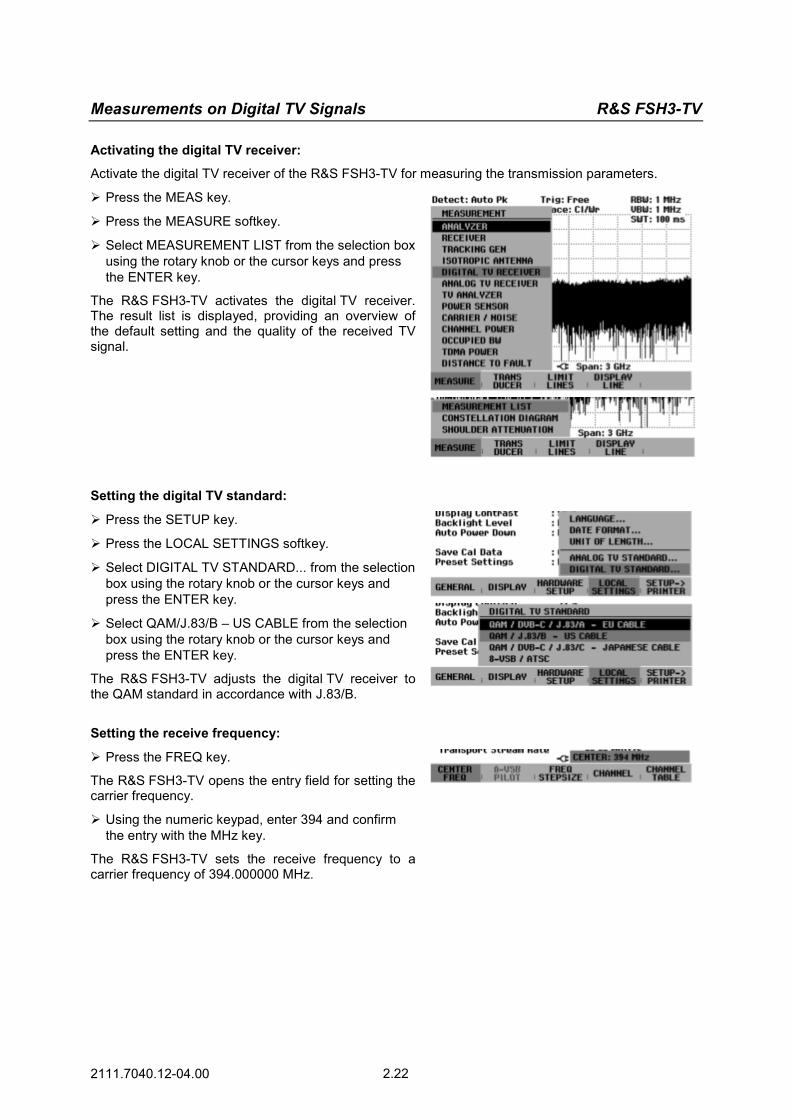
Measurements on Digital TV Signals R&S FSH3-TV
2111.7040.12-04.00 2.22
Activating the digital TV receiver:
Activate the digital TV receiver of the R&S FSH3-TV for measuring the transmission parameters.
Press the MEAS key.
Press the MEASURE softkey.
Select MEASUREMENT LIST from the selection box using the rotary knob or the cursor keys and press the ENTER key.
The R&S FSH3-TV activates the digital TV receiver. The result list is displayed, providing an overview of the default setting and the quality of the received TV signal.
Setting the digital TV standard:
Press the SETUP key.
Press the LOCAL SETTINGS softkey.
Select DIGITAL TV STANDARD... from the selection box using the rotary knob or the cursor keys and press the ENTER key.
Select QAM/J.83/B – US CABLE from the selection box using the rotary knob or the cursor keys and press the ENTER key.
The R&S FSH3-TV adjusts the digital TV receiver to the QAM standard in accordance with J.83/B.
Setting the receive frequency:
Press the FREQ key.
The R&S FSH3-TV opens the entry field for setting the carrier frequency.
Using the numeric keypad, enter 394 and confirm the entry with the MHz key.
The R&S FSH3-TV sets the receive frequency to a carrier frequency of 394.000000 MHz.
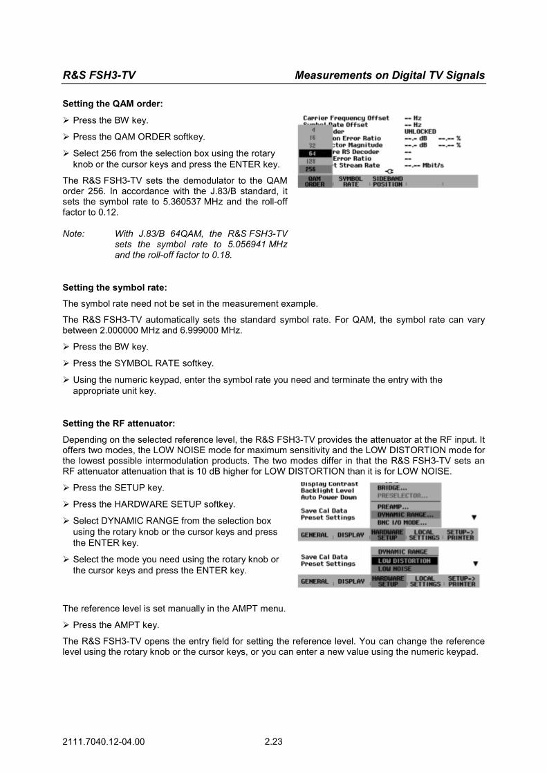
R&S FSH3-TV Measurements on Digital TV Signals
2111.7040.12-04.00 2.23
Setting the QAM order:
Press the BW key.
Press the QAM ORDER softkey.
Select 256 from the selection box using the rotary knob or the cursor keys and press the ENTER key.
The R&S FSH3-TV sets the demodulator to the QAM order 256. In accordance with the J.83/B standard, it sets the symbol rate to 5.360537 MHz and the roll-off factor to 0.12.
Note: With J.83/B 64QAM, the R&S FSH3-TV sets the symbol rate to 5.056941 MHz and the roll-off factor to 0.18.
Setting the symbol rate:
The symbol rate need not be set in the measurement example.
The R&S FSH3-TV automatically sets the standard symbol rate. For QAM, the symbol rate can vary between 2.000000 MHz and 6.999000 MHz.
Press the BW key.
Press the SYMBOL RATE softkey.
Using the numeric keypad, enter the symbol rate you need and terminate the entry with the appropriate unit key.
Setting the RF attenuator:
Depending on the selected reference level, the R&S FSH3-TV provides the attenuator at the RF input. It offers two modes, the LOW NOISE mode for maximum sensitivity and the LOW DISTORTION mode for the lowest possible intermodulation products. The two modes differ in that the R&S FSH3-TV sets an RF attenuator attenuation that is 10 dB higher for LOW DISTORTION than it is for LOW NOISE.
Press the SETUP key.
Press the HARDWARE SETUP softkey.
Select DYNAMIC RANGE from the selection box using the rotary knob or the cursor keys and press the ENTER key.
Select the mode you need using the rotary knob or the cursor keys and press the ENTER key.
The reference level is set manually in the AMPT menu.
Press the AMPT key.
The R&S FSH3-TV opens the entry field for setting the reference level. You can change the reference level using the rotary knob or the cursor keys, or you can enter a new value using the numeric keypad.
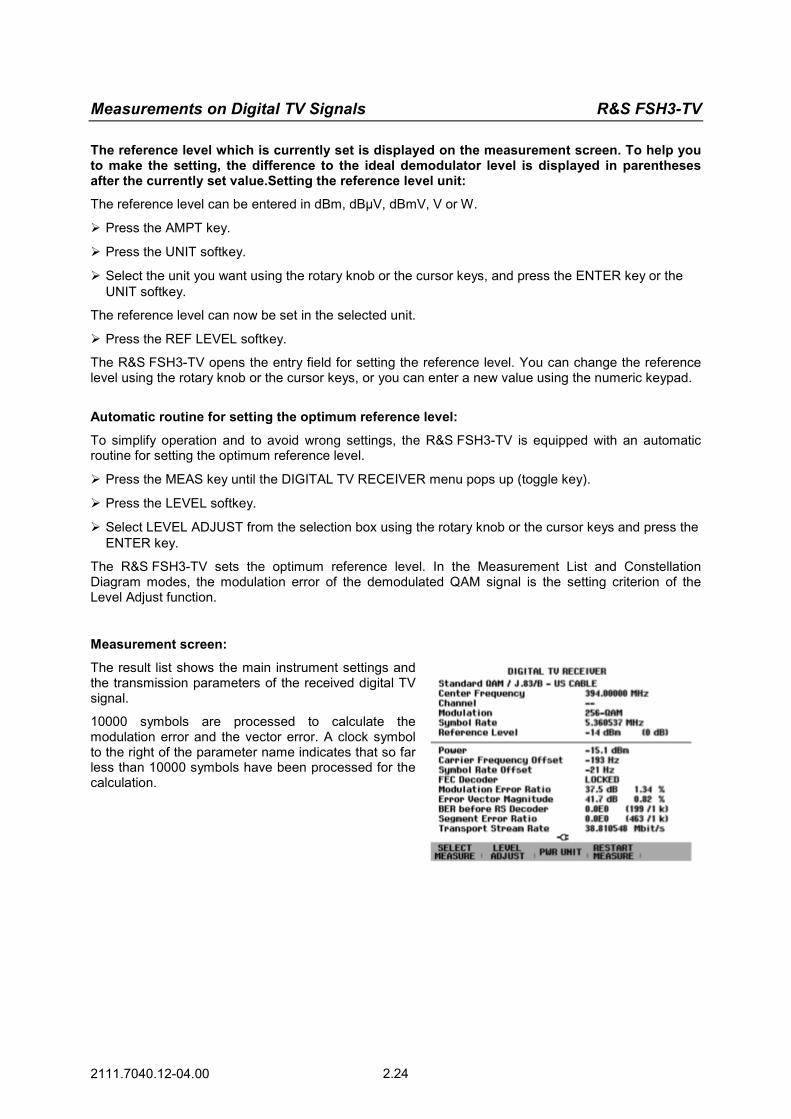
Measurements on Digital TV Signals R&S FSH3-TV
2111.7040.12-04.00 2.24
The reference level which is currently set is displayed on the measurement screen. To help you to make the setting, the difference to the ideal demodulator level is displayed in parentheses after the currently set value.Setting the reference level unit:
The reference level can be entered in dBm, dBµV, dBmV, V or W.
Press the AMPT key.
Press the UNIT softkey.
Select the unit you want using the rotary knob or the cursor keys, and press the ENTER key or the UNIT softkey.
The reference level can now be set in the selected unit.
Press the REF LEVEL softkey.
The R&S FSH3-TV opens the entry field for setting the reference level. You can change the reference level using the rotary knob or the cursor keys, or you can enter a new value using the numeric keypad.
Automatic routine for setting the optimum reference level:
To simplify operation and to avoid wrong settings, the R&S FSH3-TV is equipped with an automatic routine for setting the optimum reference level.
Press the MEAS key until the DIGITAL TV RECEIVER menu pops up (toggle key).
Press the LEVEL softkey.
Select LEVEL ADJUST from the selection box using the rotary knob or the cursor keys and press the ENTER key.
The R&S FSH3-TV sets the optimum reference level. In the Measurement List and Constellation Diagram modes, the modulation error of the demodulated QAM signal is the setting criterion of the Level Adjust function.
Measurement screen:
The result list shows the main instrument settings and the transmission parameters of the received digital TV signal.
10000 symbols are processed to calculate the modulation error and the vector error. A clock symbol to the right of the parameter name indicates that so far less than 10000 symbols have been processed for the calculation.

R&S FSH3-TV Measurements on Digital TV Signals
2111.7040.12-04.00 2.25
I/Q Constellation Display
The R&S FSH3-TV displays the complex baseband signal for the sampling times in the Cartesian coordinates system, the I/Q constellation diagram.
The following measurement example shows the individual steps used to effectively perform this measurement with the R&S FSH3-TV.
The operating steps are based on the settings of the "Measuring the Transmission Parameters" measurement example.
A digital TV test transmitter such as the TV Test Transmitter R&S SFQ is used as a signal source.
Measurement setup:
Connect the RF output of the digital TV test transmitter to the R&S FSH3-TV RF input.
Settings on the digital TV test transmitter:
Standard DVB-C in accordance with J.83/B QAM order 256 Symbol rate 5.360537 Msymb/s Frequency 394.000 MHz Level –15 dBm
Activating the constellation diagram:
Press the MEAS key until the DIGITAL TV RECEIVER menu pops up (toggle key).
Press the SELECT MEASURE softkey.
Select CONSTELLATION DIAGRAM from the selection box using the rotary knob or the cursor keys and press the ENTER key.
The R&S FSH3-TV displays the currently demodulated I/Q symbols. In the default setting, 10000 symbols are used. The constellation data is updated at a clock rate of 1000 symbols. A clock symbol is displayed below the constellation diagram until the requested number of symbols can be displayed. In addition to the constellation diagram, the parameters of the measurement parameter list are displayed.

Measurements on Digital TV Signals R&S FSH3-TV
2111.7040.12-04.00 2.26
Setting the display parameters:
In the CONT display mode, the constellation data is continuously updated. The number of the symbols displayed can be set from 1000 to 1000000 symbols in 1000 symbols steps. If there is no synchronization to the receive signals, 1000 symbols are displayed. CONT is the default setting.
In the measurement example, the constellation data is integrated infinitely.
Press the TRACE key.
Press the HOLD softkey.
As long as the demodulator is synchronized to the receive signal, the constellation data is integrated.
To calculate the modulation error and the vector error, the last 10000 symbols are used.
To calculate the bit error ratio as well as the segment and packet error ratios, all results since the last FEC synchronization are used.
Measuring the Shoulder Attenuation of a QAM Signal
The R&S FSH3-TV measures the shoulder attenuation of the received digital TV signal. With the QAM standards, it performs shoulder attenuation measurements in accordance with the ETSI TR 101 290 standard. The following measurement example shows the individual steps used to effectively measure the shoulder attenuation with the R&S FSH3-TV.
The operating steps are based on the settings of the "Measuring the Transmission Parameters" measurement example.
A digital TV test transmitter such as the TV Test Transmitter R&S SFQ is used as a signal source.
Measurement setup:
Connect the RF output of the digital TV test transmitter to the R&S FSH3-TV RF input.
Settings on the digital TV test transmitter:
Standard DVB-C in accordance with J.83/B QAM order 256 Symbol rate 5.360537 Msymb/s Frequency 394.000 MHz Level –15 dBm

R&S FSH3-TV Measurements on Digital TV Signals
2111.7040.12-04.00 2.27
Activating the shoulder attenuation measurement:
Press the MEAS key until the DIGITAL TV RECEIVER menu pops up (toggle key).
Press the SELECT MEASURE softkey.
Select SHOULDER ATTENUATION from the selection box using the rotary knob or the cursor keys and press the ENTER key.
The R&S FSH3-TV switches to the SHOULDER ATTENUATION measurement screen.
Note: In the SHOULDER ATTENUATION mode, the TS-ASI signal is not present at the multifunction BNC connector.
Setting the reference level:
The reference level is set manually in the AMPT menu. To simplify operation and to avoid wrong settings, the R&S FSH3-TV is equipped with an automatic routine for setting the optimum reference level. The setting criterion in the shoulder attenuation measurement is the measured ideal shoulder attenuation value. The routine can be applied either to the lower or the upper shoulder.
Press the MEAS key until the DIGITAL TV RECEIVER menu pops up (toggle key).
Press the LEVEL softkey.
Select LEVEL ADJUST UPPER SHOULDER or LEVEL ADJUST LOWER SHOULDER from the selection box using the rotary knob or the cursor keys and press the ENTER key.
Measurement screen:
The measurement screen displays the spectrum of the digital TV signal. The measurement parameters channel power as well as upper and lower shoulder attenuation are indicated at the lower half of the screen. Light blue frequency lines mark the frequency ranges where the shoulder attenuation values are measured.
With the 8-VSB/ATSC standard, the frequency marker "C" is additionally set to the pilot carrier. Frequency and level of the pilot carrier are displayed at the upper left of the screen.
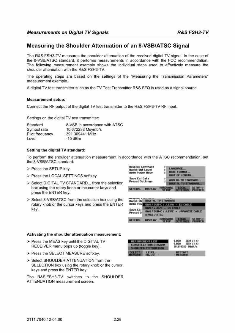
Measurements on Digital TV Signals R&S FSH3-TV
2111.7040.12-04.00 2.28
Measuring the Shoulder Attenuation of an 8-VSB/ATSC Signal
The R&S FSH3-TV measures the shoulder attenuation of the received digital TV signal. In the case of the 8-VSB/ATSC standard, it performs measurements in accordance with the FCC recommendation. The following measurement example shows the individual steps used to effectively measure the shoulder attenuation with the R&S FSH3-TV.
The operating steps are based on the settings of the "Measuring the Transmission Parameters" measurement example.
A digital TV test transmitter such as the TV Test Transmitter R&S SFQ is used as a signal source.
Measurement setup:
Connect the RF output of the digital TV test transmitter to the R&S FSH3-TV RF input.
Settings on the digital TV test transmitter:
Standard 8-VSB in accordance with ATSC Symbol rate 10.672238 Msymb/s Pilot frequency 391.309441 MHz Level -15 dBm
Setting the digital TV standard:
To perform the shoulder attenuation measurement in accordance with the ATSC recommendation, set the 8-VSB/ATSC standard.
Press the SETUP key.
Press the LOCAL SETTINGS softkey.
Select DIGITAL TV STANDARD... from the selection box using the rotary knob or the cursor keys and press the ENTER key.
Select 8-VSB/ATSC from the selection box using the rotary knob or the cursor keys and press the ENTER key.
Activating the shoulder attenuation measurement:
Press the MEAS key until the DIGITAL TV RECEIVER menu pops up (toggle key).
Press the SELECT MEASURE softkey.
Select SHOULDER ATTENUATION from the SELECTION box using the rotary knob or the cursor keys and press the ENTER key.
The R&S FSH3-TV switches to the SHOULDER ATTENUATION measurement screen.

R&S FSH3-TV Measurements on Digital TV Signals
2111.7040.12-04.00 2.29
Setting the reference level:
The reference level is set manually in the AMPT menu. To simplify operation and to avoid wrong settings, the R&S FSH3-TV is equipped with an automatic routine for setting the optimum reference level. The setting criterion for the shoulder attenuation measurement is the measured ideal shoulder attenuation value. The routine can be applied to either the lower or the upper shoulder.
Press the MEAS key until the DIGITAL TV RECEIVER menu pops up (toggle key).
Press the LEVEL softkey.
Select LEVEL ADJUST UPPER SHOULDER or LEVEL ADJUST LOWER SHOULDER from the selection box using the rotary knob or the cursor keys and press the ENTER key.
Measurement screen:
The measurement screen displays the spectrum of the digital TV signal. The measurement parameters channel power as well as upper and lower shoulder attenuation are indicated at the lower half of the screen. Light blue frequency lines mark the frequency ranges where the shoulder attenuation values are measured.
The frequency marker ‘C’ is set to the pilot carrier. Frequency and level of the pilot carrier are displayed at the upper left of the screen.
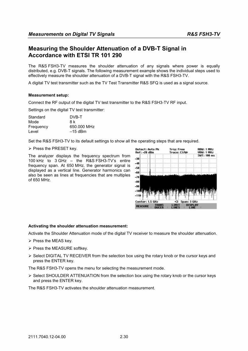
Measurements on Digital TV Signals R&S FSH3-TV
2111.7040.12-04.00 2.30
Measuring the Shoulder Attenuation of a DVB-T Signal in Accordance with ETSI TR 101 290
The R&S FSH3-TV measures the shoulder attenuation of any signals where power is equally distributed, e.g. DVB-T signals. The following measurement example shows the individual steps used to effectively measure the shoulder attenuation of a DVB-T signal with the R&S FSH3-TV.
A digital TV test transmitter such as the TV Test Transmitter R&S SFQ is used as a signal source.
Measurement setup:
Connect the RF output of the digital TV test transmitter to the R&S FSH3-TV RF input.
Settings on the digital TV test transmitter:
Standard DVB-T Mode 8 k Frequency 650.000 MHz Level –15 dBm Set the R&S FSH3-TV to its default settings to show all the operating steps that are required.
Press the PRESET key.
The analyzer displays the frequency spectrum from 100 kHz to 3 GHz – the R&S FSH3-TV’s entire frequency span. At 650 MHz, the generator signal is displayed as a vertical line. Generator harmonics can also be seen as lines at frequencies that are multiples of 650 MHz.
Activating the shoulder attenuation measurement:
Activate the Shoulder Attenuation mode of the digital TV receiver to measure the shoulder attenuation.
Press the MEAS key.
Press the MEASURE softkey.
Select DIGITAL TV RECEIVER from the selection box using the rotary knob or the cursor keys and press the ENTER key.
The R&S FSH3-TV opens the menu for selecting the measurement mode.
Select SHOULDER ATTENUATION from the selection box using the rotary knob or the cursor keys and press the ENTER key.
The R&S FSH3-TV activates the shoulder attenuation measurement.
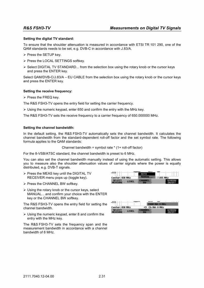
R&S FSH3-TV Measurements on Digital TV Signals
2111.7040.12-04.00 2.31
Setting the digital TV standard:
To ensure that the shoulder attenuation is measured in accordance with ETSI TR 101 290, one of the QAM standards needs to be set, e.g. DVB-C in accordance with J.83/A.
Press the SETUP key.
Press the LOCAL SETTINGS softkey.
Select DIGITAL TV STANDARD... from the selection box using the rotary knob or the cursor keys and press the ENTER key.
Select QAM/DVB-C/J.83/A – EU CABLE from the selection box using the rotary knob or the cursor keys and press the ENTER key.
Setting the receive frequency:
Press the FREQ key.
The R&S FSH3-TV opens the entry field for setting the carrier frequency.
Using the numeric keypad, enter 650 and confirm the entry with the MHz key.
The R&S FSH3-TV sets the receive frequency to a carrier frequency of 650.000000 MHz.
Setting the channel bandwidth:
In the default setting, the R&S FSH3-TV automatically sets the channel bandwidth. It calculates the channel bandwidth from the standard-dependent roll-off factor and the set symbol rate. The following formula applies to the QAM standards:
Channel bandwidth = symbol rate * (1+ roll-off factor)
For the 8-VSB/ATSC standard, the channel bandwidth is preset to 6 MHz.
You can also set the channel bandwidth manually instead of using the automatic setting. This allows you to measure also the shoulder attenuation values of carrier signals where the power is equally distributed, e.g. DVB-T signals.
Press the MEAS key until the DIGITAL TV RECEIVER menu pops up (toggle key).
Press the CHANNEL BW softkey.
Using the rotary knob or the cursor keys, select MANUAL... and confirm your choice with the ENTER key or the CHANNEL BW softkey.
The R&S FSH3-TV opens the entry field for setting the channel bandwidth.
Using the numeric keypad, enter 8 and confirm the entry with the MHz key.
The R&S FSH3-TV sets the frequency span and the measurement bandwidth in accordance with a channel bandwidth of 8 MHz.

R&S FSH3-TV Measuring the Carrier-to-Noise Ratio
2111.7040.12-04.00 2.33
Measuring the Carrier-to-Noise Ratio
The R&S FSH3-TV offers a carrier/noise measurement for measuring the ratio of carrier power to noise power. It performs the measurement in two steps. First, the carrier power of a transmission channel is measured or a reference power determined which is then used for C/N calculation. In the second step, the R&S FSH3-TV measures the noise power of an unoccupied transmission channel and calculates the ratio of carrier power to noise power.
Determining the carrier power (reference power or reference level): The R&S FSH3-TV offers the carrier power measurement for three different types of modulation. • Digital Tx
In the Digital Tx operating mode, the channel power of a reference channel is measured. This is common with digitally modulated carriers where power is equally distributed, i.e. the carrier power is independent of the modulation signal.
• Analog TV In the Analog TV operating mode, the peak power of the vision carrier is measured. This is common with amplitude-modulated TV signals.
• CW Tx In the CW Tx operating mode, the power of an unmodulated carrier is measured.
• Manual entry of a reference power or a reference level You can also enter a reference power or reference level manually. The R&S FSH3-TV then uses this value for C/N calculation.
Noise power and C/N power ratio: For noise power measurements, the R&S FSH3-TV is set to an unoccupied transmission channel where it measures the noise power in accordance with the selected channel bandwidth. If required, the R&S FSH3-TV also displays the power ratio with reference to the noise power density of the transmission channel (C/N0). C/N0 = C/N + 10 lg(channel bandwidth/Hz) Activating the C/N measurement:
Press the MEAS key.
Press the MEASURE softkey.
The menu for measurement functions opens.
Using the rotary knob or the cursor keys, select CARRIER / NOISE from the menu and confirm your choice with the ENTER key or the MEASURE softkey.
The R&S FSH3-TV activates the carrier/noise mode and starts the carrier power measurement that was selected last.
The major measurement parameter settings are available directly in the main menu of the carrier/noise measurement or can be entered using the appropriate keys.

Measuring the Carrier-to-Noise Ratio R&S FSH3-TV
2111.7040.12-04.00 2.34
Reference power/reference level
To determine the reference, you need to enter the type of reference measurement, the reference channel and the channel bandwidth of the reference channel. Selecting the reference measurement:
Press the SELECT MEASURE softkey.
Using the rotary knob or the cursor keys, select the desired measurement method to determine the reference carrier power (Digital Tx, Analog TV or CW Tx) and confirm your choice with the ENTER key or the SELECT MEASURE softkey.
The R&S FSH3-TV measures the reference in accordance with the selected modulation method.
Selecting the reference channel: Press the REF MEASURE softkey.
Using the rotary knob or the cursor keys, select the desired entry (Channel, Vision Carrier Freq, Center Freq or 8VSB Pilot Freq) and confirm your choice with the ENTER key or the F4 softkey.
You can alternatively also enter the channel center frequency after pressing the FREQ function key.
The R&S FSH3-TV measures the reference in the selected transmission channel.
Entering the channel bandwidth of the reference channel: If the reference measurement is active, press the CHANNEL BW softkey.
Enter the desired value and terminate the entry with the appropriate unit key.
The R&S FSH3-TV sets the span in accordance with the selected bandwidth. The channel center frequency is calculated when the vision carrier frequency is entered.
Selecting the reference unit: Press the LEVEL softkey.
Using the rotary knob or the cursor keys, select the desired entry (dBm, dBmV or dBµV) and confirm your choice with the ENTER key or the F2 softkey.
The measurement result of the reference measurement is displayed in the selected unit.
Manual reference entry: Press the REF MEASURE softkey.
Using the rotary knob or the cursor keys, select MAN REF POWER/LEVEL and confirm with the ENTER key or the REF MEASURE softkey.
Enter the desired reference value in the selected reference unit by means of the numeric keypad and terminate the entry with one of the unit keys.
Automatic leveling:
If the reference measurement is active, press the LEVEL softkey.
Using the rotary knob or the cursor keys, select LEVEL ADJUST and confirm your choice with the ENTER key or the F2 softkey.
Depending on the input signal, the R&S FSH3-TV is optimally levelled.
Measuring the Carrier-to-Noise Ratio R&S FSH3-TV
2111.7040.12-04.00 2.34
To determine the reference, you need to enter the type of reference measurement, the reference channel and the channel bandwidth of the reference channel. Selecting the reference measurement: Press the SELECT MEASURE softkey.
Using the rotary knob or the cursor keys, select the desired measurement method to determine the reference carrier power (Digital Tx, Analog TV or CW Tx) and confirm your choice with the ENTER key or the SELECT MEASURE softkey.
The R&S FSH3-TV measures the reference in accordance with the selected modulation method.
Selecting the reference channel: Press the REF MEASURE softkey.
Using the rotary knob or the cursor keys, select the desired entry (Channel, Vision Carrier Freq, Center Freq or 8VSB Pilot Freq) and confirm your choice with the ENTER key or the F4 softkey.
You can alternatively also enter the channel center frequency after pressing the FREQ function key.
The R&S FSH3-TV measures the reference in the selected transmission channel.
Entering the channel bandwidth of the reference channel: If the reference measurement is active, press the CHANNEL BW softkey.
Enter the desired value and terminate the entry with the appropriate unit key.
The R&S FSH3-TV sets the span in accordance with the selected bandwidth. The channel center frequency is calculated when the vision carrier frequency is entered.
Selecting the reference unit: Press the LEVEL softkey.
Using the rotary knob or the cursor keys, select the desired entry (dBm, dBmV or dBµV) and confirm your choice with the ENTER key or the F2 softkey.
The measurement result of the reference measurement is displayed in the selected unit.
Manual reference entry: Press the REF MEASURE softkey.
Using the rotary knob or the cursor keys, select MAN REF POWER/LEVEL and confirm with the ENTER key or the REF MEASURE softkey.
Enter the desired reference value in the selected reference unit by means of the numeric keypad and terminate the entry with one of the unit keys.
Automatic leveling: If the reference measurement is active, press the LEVEL softkey.
Using the rotary knob or the cursor keys, select LEVEL ADJUST and confirm your choice with the ENTER key or the F2 softkey.
Depending on the input signal, the R&S FSH3-TV is optimally levelled.

R&S FSH3-TV Measuring the Carrier-to-Noise Ratio
2111.7040.12-04.00 2.35
Measuring the noise power
Enter an unoccupied transmission channel and its channel bandwidth to determine the noise power. Selecting the result display: Press the SELECT MEASURE softkey.
Using the rotary knob or the cursor keys, select the desired result display (C/N or C/N0) and confirm your choice with the ENTER key or the F1 softkey.
The R&S FSH3-TV outputs the power ratio according to the selected result display.
Selecting the unoccupied transmission channel: Press the NOISE MEASURE softkey.
Using the rotary knob or the cursor keys, select the desired entry (Channel, Vision Carrier Freq, Center Freq or 8VSB Pilot Freq) and confirm your choice with the ENTER key or the F5 softkey.
You can alternatively also enter the channel center frequency after pressing the FREQ function key. The R&S FSH3-TV measures the noise power in the selected transmission channel.
Entering the channel bandwidth of the noise channel: If the noise power measurement is active, press the CHANNEL BW softkey.
Enter the desired value and terminate the entry with the appropriate unit key.
The R&S FSH3-TV sets the span in accordance with the selected bandwidth. The channel center frequency is calculated when the vision carrier frequency is entered.
Automatic leveling: If the noise power measurement is active, press the LEVEL softkey.
Using the rotary knob or the cursor keys, select LEVEL ADJUST and confirm your choice with the ENTER key or the F2 softkey.
Depending on the input signal, the R&S FSH3-TV is optimally levelled.
Blanking out the result display: The C/N ratio or the reference is indicated at the bottom of the display. This insertion can be deactivated.
Press the NOISE MEASURE or REF MEASURE softkey.
Using the rotary knob or the cursor keys, select DISPLAY OFF and confirm your choice with the ENTER key or the F4 or F5 softkey.
The R&S FSH3-TV blanks out the result display. Inserting the result display: Press the NOISE MEASURE or REF MEASURE softkey.
Using the rotary knob or the cursor keys, select DISPLAY ON and confirm your choice with the ENTER key or the F4 or F5 softkey.
The R&S FSH3-TV inserts the result display at the bottom of the display.

Measurements on Cable TV Systems R&S FSH3-TV
2111.7040.12-04.00 2.36
Measurements on Cable TV Systems
Use the Preselector R&S FSHTV-Z60 to perform measurements on cable TV systems. The preselector is connected ahead of the R&S FSH3-TV and reduces the cable TV spectrum and thus the total power at the first mixer. As a result, the dynamic range is increased.
Measuring the Composite Triple Beat Ratio
For measuring the ratio of the composite triple beat (CTB) intermodulation products to the carrier power, the R&S FSH3-TV offers the CTB measurement in the CABLE TV menu. It performs the measurement in two steps in accordance with the EN 50083 standard. First, the reference power is measured, or a reference power is determined which is then used to calculate the CTB ratio. In the second step, the R&S FSH3-TV measures the power of the CTB intermodulation products in an unoccupied transmission channel and calculates their ratio to the reference power. In order to increase the measurement dynamic range, the R&S FSH3-TV measures the noise power at a spacing of 100 kHz from the vision carrier and takes this into account in computing the CTB measured value. The correction is limited to 6 dB. The following measurement example shows the individual steps used to effectively perform this measurement with the R&S FSH3-TV.
For the measurement example to be reproducible, only an analog TV test transmitter such as the TV Test Transmitter R&S SFM together with the CCVS + Component Generator R&S SAF and two signal generators such as the Signal Generator R&S SML are used as signal sources.
Measurement setup:
Connect the R&S SAF video output to the R&S SFM video input. Add the RF output signals via a coupler and connect them to the R&S FSH3-TV RF input. Settings on the video signal generator: Standard PAL, 625 lines Settings on the analog TV test transmitter: Standard B/G, FM-IRT-A2 dual-channel sound Group delay general Frequency 210.25 MHz Level –20 dBm Settings on the first signal generator: Frequency 217.25 MHz Level –20 dBm Settings on the second signal generator: Frequency 224.25 MHz Level –20 dBm
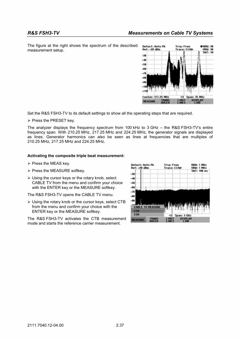
R&S FSH3-TV Measurements on Cable TV Systems
2111.7040.12-04.00 2.37
The figure at the right shows the spectrum of the described measurement setup.
Set the R&S FSH3-TV to its default settings to show all the operating steps that are required.
Press the PRESET key.
The analyzer displays the frequency spectrum from 100 kHz to 3 GHz – the R&S FSH3-TV’s entire frequency span. With 210.25 MHz, 217.25 MHz and 224.25 MHz, the generator signals are displayed as lines. Generator harmonics can also be seen as lines at frequencies that are multiples of 210.25 MHz, 217.25 MHz and 224.25 MHz.
Activating the composite triple beat measurement: Press the MEAS key.
Press the MEASURE softkey.
Using the cursor keys or the rotary knob, select CABLE TV from the menu and confirm your choice with the ENTER key or the MEASURE softkey.
The R&S FSH3-TV opens the CABLE TV menu.
Using the rotary knob or the cursor keys, select CTB from the menu and confirm your choice with the ENTER key or the MEASURE softkey.
The R&S FSH3-TV activates the CTB measurement mode and starts the reference carrier measurement.

Measurements on Cable TV Systems R&S FSH3-TV
2111.7040.12-04.00 2.38
Measuring the Reference Power
The reference power is either measured in an analog TV channel or can be defined manually. If the vision carriers are modulated negatively, the reference power is the vision carrier power at the time of the sync pulse.
In the example, the reference channel is the analog TV signal with a vision carrier frequency of 210.25 MHz.
Press the MEAS key.
Press the REF MEASURE softkey.
Using the cursor keys or the rotary knob, select VISION CARR FREQ... from the menu and confirm your choice with the ENTER key or the REF MEASURE softkey.
The R&S FSH3-TV opens the entry field for setting the vision carrier frequency.
Using the numeric keypad, enter 210.25 and confirm the entry with the MHz key.
The R&S FSH3-TV sets the receive frequency to a vision carrier frequency of 210.250000 MHz.
The measurement screen displays the analog TV channel spectrum with a vision carrier frequency of 210.250 MHz. The frequency span corresponds to the channel bandwidth of the analog TV standard set in the SETUP – LOCAL SETTINGS menu.
The channel bandwidth can also be set manually.
Press the MEAS key.
Press the CHANNEL BW softkey.
The R&S FSH3-TV opens the entry field for setting the channel bandwidth.
Using the numeric keypad, enter 7 and confirm the entry with the MHz key.
The R&S FSH3-TV sets the channel bandwidth to 7 MHz.

R&S FSH3-TV Measurements on Cable TV Systems
2111.7040.12-04.00 2.39
Setting the reference level:
The reference level is set manually in the AMPT menu. To simplify operation and to prevent incorrect measurements, the R&S FSH3-TV has an automatic routine for setting the reference level. During the reference level measurement, the LEVEL ADJUST function measures the maximum receive level and sets the reference level accordingly.
Press the MEAS key.
If the reference measurement is active, press the LEVEL softkey.
Using the rotary knob or the cursor keys, select LEVEL ADJUST and confirm your choice with the ENTER key or the LEVEL softkey.
The measurement screen displays the reference channel spectrum. The measured reference power is displayed in the lower half of the screen. The reference level is output in dBm, dBµV or dBmV.
Press the MEAS key.
Press the LEVEL softkey.
Using the rotary knob or the cursor keys, select the unit you want and confirm your choice with the ENTER key or the LEVEL softkey.
The reference measurement result is displayed in the selected unit.
Measuring the Composite Triple Beat Distortion
Composite triple beat distortion refers to unwanted intermodulation products of the vision carriers that occur at nonlinearities. They are third-order intermodulation products and occur with vision carrier frequencies at the channel spacings. In cable TV systems, the individual intermodulation products are "piling up".
The R&S FSH3-TV measures these interference products in an unoccupied channel and determines their ratio to the reference power.
In the measurement example, CTB products occur at 203.25 MHz, 231.25 MHz and 637.25 MHz, for example. The composite triple beat distortion is measured in a channel with a vision carrier frequency of 203.25 MHz.
The figure at the right shows the frequency spectrum of the measurement example and explains how CTB products occur.

Measurements on Cable TV Systems R&S FSH3-TV
2111.7040.12-04.00 2.40
Switchover to the CTB measurement:
Press the MEAS key.
Press the CTB MEASURE softkey.
Using the cursor keys or the rotary knob, select VISION CARR FREQ... from the menu and confirm your choice with the ENTER key or the CTB MEASURE softkey.
The R&S FSH3-TV opens the entry field for setting the vision carrier frequency.
Using the numeric keypad, enter 203.25 and confirm the entry with the MHz key.
The R&S FSH3-TV sets the receive frequency to a vision carrier frequency of 203.250000 MHz.
Setting the reference level:
The reference level is set manually in the AMPT menu. To simplify operation and to prevent incorrect measurements, the R&S FSH3-TV has an automatic routine for setting the reference level. During the CTB measurement, the LEVEL ADJUST function measures the power of the CTB noise "pile" depending on the reference level and then sets the reference level where the CTB noise power is lowest. This ensures that the R&S FSH3-TV is optimally set, irrespective of the channels and levels of the input signal.
Press the MEAS key.
If the CTB measurement is active, press the LEVEL softkey.
Confirm with the ENTER key or the LEVEL softkey.
The measurement screen displays the frequency spectrum around the vision carrier with a span of 50 kHz. The measurement settings are made in compliance with the EN 50083 test specification.
The measured CTB ratio is displayed in the lower half of the measurement screen. The reference power used for calculations is displayed in the upper left corner of the screen.

R&S FSH3-TV Measurements on Cable TV Systems
2111.7040.12-04.00 2.41
Measuring the Composite Second Order Ratio
For measuring the ratio of the composite second order (CSO) intermodulation products to the carrier power in accordance with the EN 50083 standard, the R&S FSH3-TV offers the CSO measurement in the CABLE TV menu. It performs the measurement in two steps. First, the reference power is measured, or a reference power is determined which is then used to calculate the CSO ratio. In the second step, the R&S FSH3-TV measures the power of the CSO intermodulation products in an unoccupied transmission channel and calculates their ratio to the reference power.
In order to increase the measurement dynamic range, the R&S FSH3-TV measures the noise power at a spacing of 100 kHz from the vision carrier and takes this into account in computing the CSO measured value. The correction is limited to 6 dB.
The following measurement example shows the individual steps used to effectively perform this measurement with the R&S FSH3-TV.
For the measurement example to be reproducible, only an analog TV test transmitter such as the TV Test Transmitter R&S SFM together with the CCVS + Component Generator R&S SAF and a signal generator such as the Signal Generator R&S SML are used as signal sources.
Measurement setup:
Connect the R&S SAF video output to the R&S SFM video input. Add the RF output signals via a coupler and connect them to the R&S FSH3-TV RF input. Settings on the video signal generator: Standard PAL, 625 lines Settings on the analog TV test transmitter: Standard B/G, FM-IRT-A2 dual-channel sound Group delay general Frequency 521.25 MHz Level –20 dBm Settings on the signal generator: Frequency 569.25 MHz Level –20 dBm
The figure at the right shows the spectrum of the described measurement setup.
Set the R&S FSH3-TV to its default settings to show all the operating steps that are required.
Press the PRESET key.
The analyzer displays the frequency spectrum from 100 kHz to 3 GHz – the R&S FSH3-TV’s entire frequency span. With 521.25 MHz and 569.25 MHz, the generator signals are displayed as lines.

Measurements on Cable TV Systems R&S FSH3-TV
2111.7040.12-04.00 2.42
Generator harmonics can also be seen as lines at frequencies that are multiples of 521.25 MHz and 569.25 MHz.
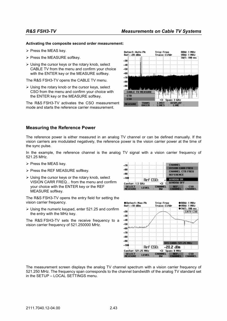
R&S FSH3-TV Measurements on Cable TV Systems
2111.7040.12-04.00 2.43
Activating the composite second order measurement: Press the MEAS key.
Press the MEASURE softkey.
Using the cursor keys or the rotary knob, select CABLE TV from the menu and confirm your choice with the ENTER key or the MEASURE softkey.
The R&S FSH3-TV opens the CABLE TV menu.
Using the rotary knob or the cursor keys, select CSO from the menu and confirm your choice with the ENTER key or the MEASURE softkey.
The R&S FSH3-TV activates the CSO measurement mode and starts the reference carrier measurement.
Measuring the Reference Power
The reference power is either measured in an analog TV channel or can be defined manually. If the vision carriers are modulated negatively, the reference power is the vision carrier power at the time of the sync pulse.
In the example, the reference channel is the analog TV signal with a vision carrier frequency of 521.25 MHz.
Press the MEAS key.
Press the REF MEASURE softkey.
Using the cursor keys or the rotary knob, select VISION CARR FREQ... from the menu and confirm your choice with the ENTER key or the REF MEASURE softkey.
The R&S FSH3-TV opens the entry field for setting the vision carrier frequency.
Using the numeric keypad, enter 521.25 and confirm the entry with the MHz key.
The R&S FSH3-TV sets the receive frequency to a vision carrier frequency of 521.250000 MHz.
The measurement screen displays the analog TV channel spectrum with a vision carrier frequency of 521.250 MHz. The frequency span corresponds to the channel bandwidth of the analog TV standard set in the SETUP – LOCAL SETTINGS menu.

Measurements on Cable TV Systems R&S FSH3-TV
2111.7040.12-04.00 2.44
The channel bandwidth can also be set manually.
Press the MEAS key.
Press the CHANNEL BW softkey.
The R&S FSH3-TV opens the entry field for setting the channel bandwidth.
Using the numeric keypad, enter 8 and confirm the entry with the MHz key.
The R&S FSH3-TV sets the channel bandwidth to 8 MHz.
Setting the reference level:
The reference level is set manually in the AMPT menu. To simplify operation and to prevent incorrect measurements, the R&S FSH3-TV has an automatic routine for setting the reference level. During the reference level measurement, the LEVEL ADJUST function measures the maximum receive level and sets the reference level accordingly.
Press the MEAS key.
If the reference measurement is active, press the LEVEL softkey.
Using the rotary knob or the cursor keys, select LEVEL ADJUST and confirm your choice with the ENTER key or the LEVEL softkey.
The measurement screen displays the reference channel spectrum. The measured reference power is displayed in the lower half of the screen. The reference level is output in dBm, dBµV or dBmV.
Press the MEAS key.
Press the LEVEL softkey.
Using the rotary knob or the cursor keys, select the unit you want and confirm your choice with the ENTER key or the LEVEL softkey.
The reference measurement result is displayed in the selected unit.
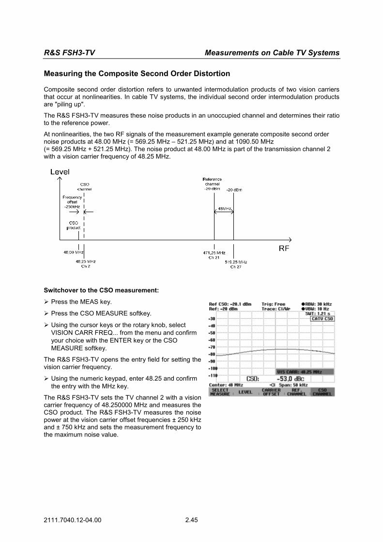
R&S FSH3-TV Measurements on Cable TV Systems
2111.7040.12-04.00 2.45
Measuring the Composite Second Order Distortion
Composite second order distortion refers to unwanted intermodulation products of two vision carriers that occur at nonlinearities. In cable TV systems, the individual second order intermodulation products are "piling up".
The R&S FSH3-TV measures these noise products in an unoccupied channel and determines their ratio to the reference power.
At nonlinearities, the two RF signals of the measurement example generate composite second order noise products at 48.00 MHz (= 569.25 MHz – 521.25 MHz) and at 1090.50 MHz (= 569.25 MHz + 521.25 MHz). The noise product at 48.00 MHz is part of the transmission channel 2 with a vision carrier frequency of 48.25 MHz.
Switchover to the CSO measurement:
Press the MEAS key.
Press the CSO MEASURE softkey.
Using the cursor keys or the rotary knob, select VISION CARR FREQ... from the menu and confirm your choice with the ENTER key or the CSO MEASURE softkey.
The R&S FSH3-TV opens the entry field for setting the vision carrier frequency.
Using the numeric keypad, enter 48.25 and confirm the entry with the MHz key.
The R&S FSH3-TV sets the TV channel 2 with a vision carrier frequency of 48.250000 MHz and measures the CSO product. The R&S FSH3-TV measures the noise power at the vision carrier offset frequencies ± 250 kHz and ± 750 kHz and sets the measurement frequency to the maximum noise value.

Measurements on Cable TV Systems R&S FSH3-TV
2111.7040.12-04.00 2.46
Setting the carrier frequency offset:
The frequency offset to the vision carrier can be set manually.
Press the MEAS key.
Press the CARRIER OFFSET softkey.
Using the cursor keys or the rotary knob, select the carrier frequency offset you need from the menu and confirm your choice with the ENTER key or the CARRIER OFFSET softkey.
The R&S FSH3-TV measures the distortion at the frequency vision carrier frequency plus offset frequency and calculates the CSO ratio.
Setting the reference level:
The reference level is set manually in the AMPT menu. To simplify operation and to prevent incorrect measurements, the R&S FSH3-TV has an automatic routine for setting the reference level. During the CSO measurement, the LEVEL ADJUST function measures the power of the CSO-specific vision carrier offset frequencies. Depending on the reference level, the CSO noise power of the offset frequency is measured which has yielded the highest power. The R&S FSH3-TV sets the reference level where the CSO noise power is lowest. This ensures that the R&S FSH3-TV is optimally set, irrespective of the channels and levels of the input signal.
Press the MEAS key.
If the CSO measurement is active, press the LEVEL softkey.
Using the rotary knob or the cursor keys, select LEVEL ADJUST and confirm your choice with the ENTER key or the LEVEL softkey.
The measurement screen displays the frequency spectrum around the vision carrier with a span of 50 kHz. The measurement settings are made in compliance with the EN 50083 test specification.
The measured CSO ratio is displayed in the lower half of the measurement screen. The reference power used for the calculation is displayed in the upper left corner of the screen.

R&S FSH3-TV Measurements on Cable TV Systems
2111.7040.12-04.00 2.47
Measuring the Frequency Response of the Cable TV System
One of the most important parameters of cable TV systems is the system’s frequency response. To measure this parameter, the R&S FSH3-TV provides the scan mode in the receiver mode. For example, the frequency response can be measured by measuring the vision carrier power of the analog TV channels.
For the receiver mode, you need the option R&S FSH-K3 (Order No. 1157.3429.02).
Using the R&S FSH View PC software, generate a channel table that contains only the analog TV channels to be used for determining the frequency response. Then load this channel table to the R&S FSH3-TV.
Start R&S FSH View on the PC.
Open the Channel Table Editor tool.
Enter the channels for determining the frequency response of the cable network into the channel table.
In the measurement example, the frequency response is to be determined by measuring the vision carriers with the frequencies
48.25 MHz 210.25 MHz 471.25 MHz 703.25 MHz
Save the channel table.
Close the Channel Table Editor.
Open the Channel Table Control tool.
Transfer the channel table to the R&S FSH3-TV.
Select the Receiver mode.
Press the MEAS key.
Press the MEASURE softkey.
Using the rotary knob or the cursor keys, select RECEIVER from the menu and confirm with the ENTER key or the MEASURE softkey.
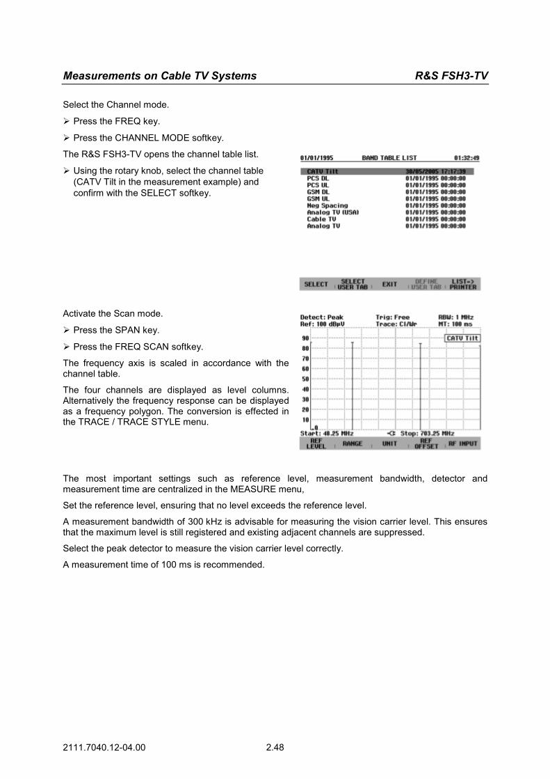
Measurements on Cable TV Systems R&S FSH3-TV
2111.7040.12-04.00 2.48
Select the Channel mode.
Press the FREQ key.
Press the CHANNEL MODE softkey.
The R&S FSH3-TV opens the channel table list.
Using the rotary knob, select the channel table (CATV Tilt in the measurement example) and confirm with the SELECT softkey.
Activate the Scan mode.
Press the SPAN key.
Press the FREQ SCAN softkey.
The frequency axis is scaled in accordance with the channel table.
The four channels are displayed as level columns. Alternatively the frequency response can be displayed as a frequency polygon. The conversion is effected in the TRACE / TRACE STYLE menu.
The most important settings such as reference level, measurement bandwidth, detector and measurement time are centralized in the MEASURE menu,
Set the reference level, ensuring that no level exceeds the reference level.
A measurement bandwidth of 300 kHz is advisable for measuring the vision carrier level. This ensures that the maximum level is still registered and existing adjacent channels are suppressed.
Select the peak detector to measure the vision carrier level correctly.
A measurement time of 100 ms is recommended.

R&S FSH3-TV Measurements on Cable TV Systems
2111.7040.12-04.00 2.49
For a better evaluation of the frequency response, change the level range.
Press the AMPT key.
Press the RANGE softkey.
Using the rotary knob or the cursor keys, select the desired level range and confirm your choice with the ENTER key or the RANGE softkey.
In the measurement example a level range of 1 dB/div has been selected.
Using the marker function, the frequency response results can also be displayed numerically.
Press the MARKER key.
Press the MARKER MODE softkey.
Using the rotary knob or the cursor keys, select MULTI MARKER and confirm your choice with the ENTER key or the MARKER MODE softkey.
Activate markers 1 to 4 and assign them to the four measurement channels.
Activate marker 1 and assign it to channel 2.
Press the MARKER softkey and confirm with the ENTER key or the MARKER softkey.
Using the rotary knob, assign MARKER 1 to channel 2.
Activate marker 2 and assign it to channel 10.
Press the MARKER key.
Using the rotary knob or the cursor keys, select MARKER 2 and confirm your choice with the ENTER key or the MARKER softkey.

Measurements on Cable TV Systems R&S FSH3-TV
2111.7040.12-04.00 2.50
Activate markers 3 and 4 accordingly and assign them to channels 21 and 50.
Activate markers 3 and 4 analogously to the marker 2 example and assign them to channels 21 and 50.
Insert the marker list.
Press the MKR LIST VIEW softkey.
The R&S FSH3-TV inserts the measured level values of the measurement channels.
Instead of the channel information, the frequency of the measurement channels can be alternatively displayed in the list.
Press the MARKER MODE softkey.
Using the rotary knob or the cursor keys, select FREQUENCY and confirm your choice with the ENTER key or the MARKER MODE softkey.
Press the MKR LIST VIEW softkey.
The R&S FSH3-TV inserts the frequency of the measurement channels plus the associated measured level values.
Note: For further detailed operating instructions, refer to the ‘Operation in Receiver Mode’ section.

R&S FSH3-TV Power Measurements Using the Power Sensor
2111.7040.12-04.00 2.51
Power Measurements Using the Power Sensor
For highly accurate power measurements, the R&S FSH3-TV provides the Power Sensors R&S FSH-Z1 or R&S FSH-Z18 as options. They measure power in the span 10 MHz to 8 GHz or 10 MHz to 18 GHz, respectively.
The power sensors are controlled and powered via a special RS-232-C interface at the top of the instrument.
RF connector(Device under Test)
Power SensorR&S FSH-Z1 orR&S FSH-Z18
Power Sensorconnector
The continuous power applied to the power sensor’s input must not exceed 400 mW (26 dBm). However, brief (≤10 µs) power peaks up to 1 W (30 dBm) are permissible. Higher input powers can destroy the sensor. An attenuator pad must be used to ensure that the maximum permissible power for the sensor is never exceeded when measurements are made on high-power transmitters.
Connect the power sensor cable to the R&S FSH3-TV’s power sensor connector and screw it into position.
Press the MEAS key.
Press the MEASURE softkey.
Using the cursor keys or the rotary knob, select the POWER SENSOR menu item and confirm your selection with the ENTER key or the MEASURE softkey.
The R&S FSH3-TV opens the screen for power measurements. If a power sensor has not been connected, no measured value is displayed. If a power sensor has been connected, the R&S FSH3-TV sets up a connection via the RS-232-C interface and, after a few seconds, displays the measured power.
If there are any communications problems with the power sensor, the R&S FSH3-TV outputs error messages (sensor error: error number) indicating the possible causes (see operating manual).
To compensate for internal offset of the power meter, the power sensor needs to be compensated before starting the measurement.
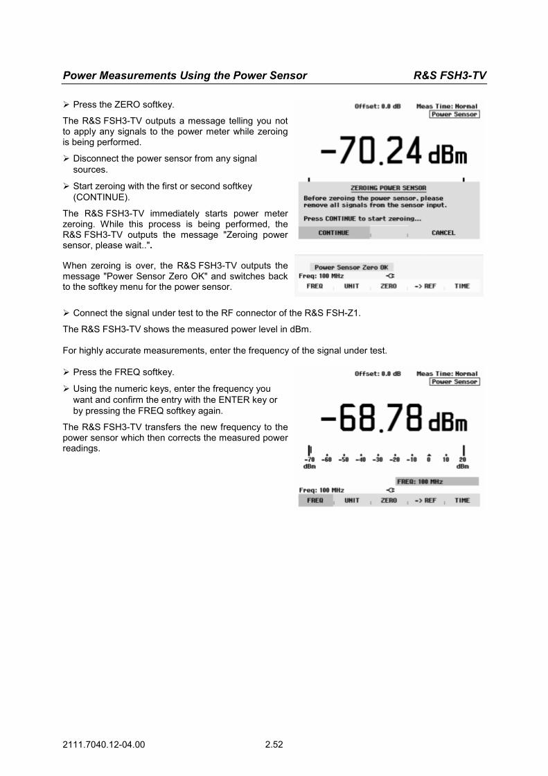
Power Measurements Using the Power Sensor R&S FSH3-TV
2111.7040.12-04.00 2.52
Press the ZERO softkey.
The R&S FSH3-TV outputs a message telling you not to apply any signals to the power meter while zeroing is being performed.
Disconnect the power sensor from any signal sources.
Start zeroing with the first or second softkey (CONTINUE).
The R&S FSH3-TV immediately starts power meter zeroing. While this process is being performed, the R&S FSH3-TV outputs the message "Zeroing power sensor, please wait..".
When zeroing is over, the R&S FSH3-TV outputs the message "Power Sensor Zero OK" and switches back to the softkey menu for the power sensor.
Connect the signal under test to the RF connector of the R&S FSH-Z1.
The R&S FSH3-TV shows the measured power level in dBm. For highly accurate measurements, enter the frequency of the signal under test. Press the FREQ softkey.
Using the numeric keys, enter the frequency you want and confirm the entry with the ENTER key or by pressing the FREQ softkey again.
The R&S FSH3-TV transfers the new frequency to the power sensor which then corrects the measured power readings.
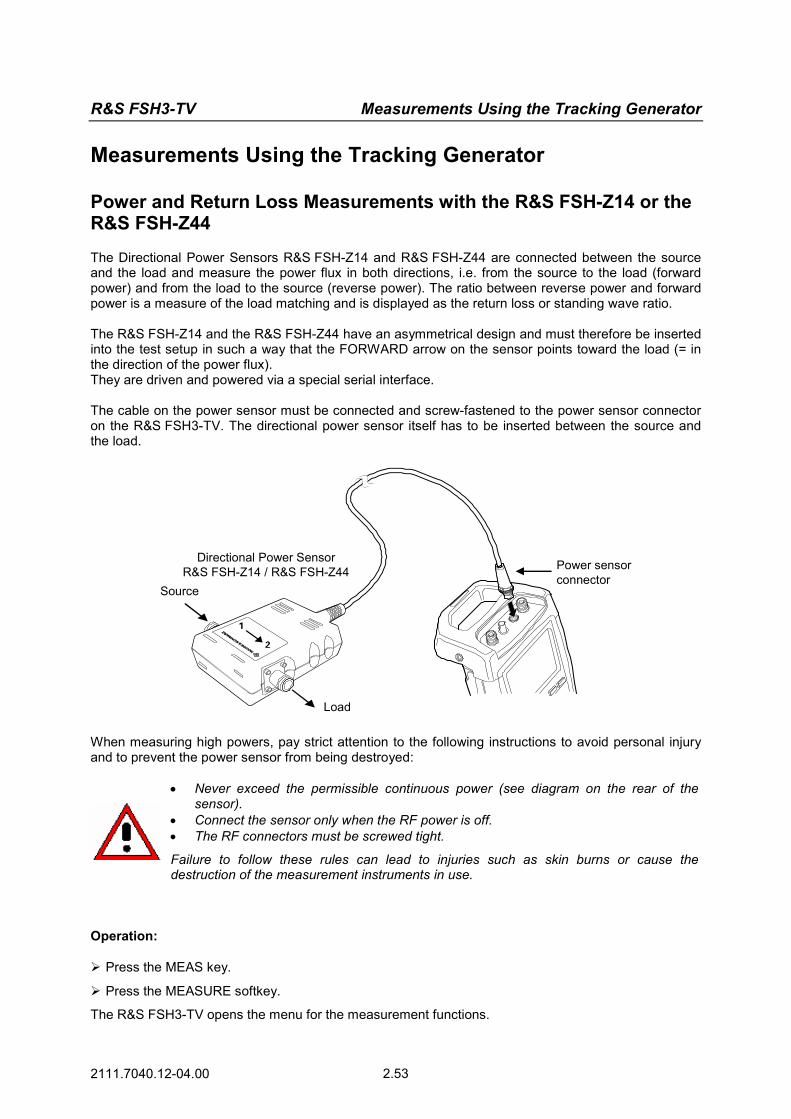
R&S FSH3-TV Measurements Using the Tracking Generator
2111.7040.12-04.00 2.53
Measurements Using the Tracking Generator
Power and Return Loss Measurements with the R&S FSH-Z14 or the R&S FSH-Z44
The Directional Power Sensors R&S FSH-Z14 and R&S FSH-Z44 are connected between the source and the load and measure the power flux in both directions, i.e. from the source to the load (forward power) and from the load to the source (reverse power). The ratio between reverse power and forward power is a measure of the load matching and is displayed as the return loss or standing wave ratio. The R&S FSH-Z14 and the R&S FSH-Z44 have an asymmetrical design and must therefore be inserted into the test setup in such a way that the FORWARD arrow on the sensor points toward the load (= in the direction of the power flux). They are driven and powered via a special serial interface. The cable on the power sensor must be connected and screw-fastened to the power sensor connector on the R&S FSH3-TV. The directional power sensor itself has to be inserted between the source and the load.
Directional Power SensorR&S FSH-Z14 / R&S FSH-Z44
Source
Load
Power sensorconnector
When measuring high powers, pay strict attention to the following instructions to avoid personal injury and to prevent the power sensor from being destroyed:
• Never exceed the permissible continuous power (see diagram on the rear of the sensor).
• Connect the sensor only when the RF power is off. • The RF connectors must be screwed tight.
Failure to follow these rules can lead to injuries such as skin burns or cause the destruction of the measurement instruments in use.
Operation: Press the MEAS key.
Press the MEASURE softkey.
The R&S FSH3-TV opens the menu for the measurement functions.
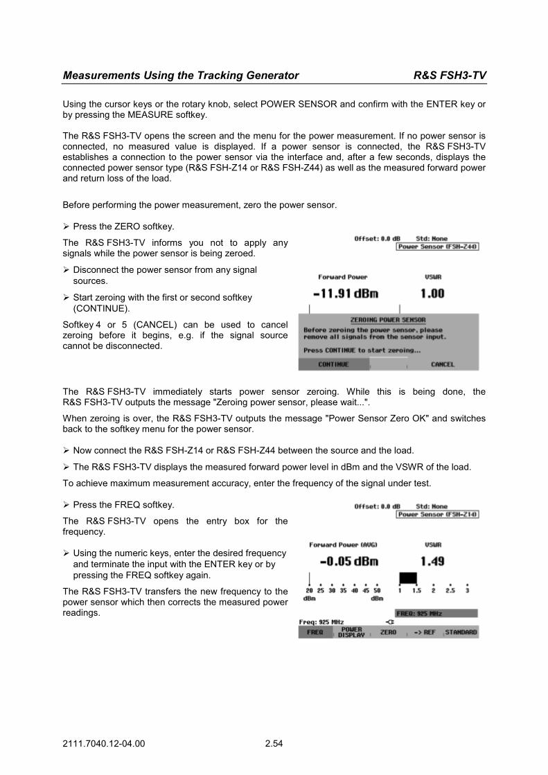
Measurements Using the Tracking Generator R&S FSH3-TV
2111.7040.12-04.00 2.54
Using the cursor keys or the rotary knob, select POWER SENSOR and confirm with the ENTER key or by pressing the MEASURE softkey. The R&S FSH3-TV opens the screen and the menu for the power measurement. If no power sensor is connected, no measured value is displayed. If a power sensor is connected, the R&S FSH3-TV establishes a connection to the power sensor via the interface and, after a few seconds, displays the connected power sensor type (R&S FSH-Z14 or R&S FSH-Z44) as well as the measured forward power and return loss of the load.
Before performing the power measurement, zero the power sensor. Press the ZERO softkey.
The R&S FSH3-TV informs you not to apply any signals while the power sensor is being zeroed.
Disconnect the power sensor from any signal sources.
Start zeroing with the first or second softkey (CONTINUE).
Softkey 4 or 5 (CANCEL) can be used to cancel zeroing before it begins, e.g. if the signal source cannot be disconnected.
The R&S FSH3-TV immediately starts power sensor zeroing. While this is being done, the R&S FSH3-TV outputs the message "Zeroing power sensor, please wait...". When zeroing is over, the R&S FSH3-TV outputs the message "Power Sensor Zero OK" and switches back to the softkey menu for the power sensor. Now connect the R&S FSH-Z14 or R&S FSH-Z44 between the source and the load.
The R&S FSH3-TV displays the measured forward power level in dBm and the VSWR of the load.
To achieve maximum measurement accuracy, enter the frequency of the signal under test. Press the FREQ softkey.
The R&S FSH3-TV opens the entry box for the frequency. Using the numeric keys, enter the desired frequency
and terminate the input with the ENTER key or by pressing the FREQ softkey again.
The R&S FSH3-TV transfers the new frequency to the power sensor which then corrects the measured power readings.

R&S FSH3-TV Measurements Using the Tracking Generator
2111.7040.12-04.00 2.55
Two-Port Transmission Measurements
For measurements of the gain or attenuation of two-port devices, the R&S FSH3-TV provides a tracking generator which generates a signal exactly at the current frequency of the R&S FSH3-TV. Press the MEAS key.
Press the MEASURE softkey.
The measurement function menu opens.
Using the cursor keys or the rotary knob, select the TRACKING GEN menu item and confirm your selection with the ENTER key or the MEAS softkey.
The R&S FSH3-TV switches on the tracking generator and calls up its softkey menu. When the tracking generator is switched on, the R&S FSH3-TV displays Track Gen Uncal . This indicates that tracking generator measurements are uncalibrated.
Before calibration, the span you want should be set because calibration is valid only for the calibrated span and the reference. Changing the parameters after calibration invalidates calibration.
Press the FREQ key.
Using the numeric keys, enter the center frequency.
Press the SPAN key.
Using the numeric keys, enter the span.
Alternately, the start and stop frequencies can be entered using the START and STOP softkeys in the frequency menu. Calibrate the R&S FSH3-TV for the transfer function measurement. The following example shows a scalar measurement of the transmission function. If the option R&S FSH-K2 is installed, the measurement must first be switched to scalar. Press the MEAS key.
Press the MEAS MODE softkey.
Using the rotary knob or cursor keys, select SCALAR.
Confirm with the ENTER key or the MEAS MODE softkey.
In the main menu for the tracking generator, press the MEAS key.
Press the TRANSM CAL softkey.
The R&S FSH3-TV now prompts you to connect the RF input to the tracking generator’s output so that calibration can be carried out.
Connect the RF output to the generator’s input without the DUT.
Press the CONTINUE softkey to start calibration.
During calibration, the R&S FSH3-TV outputs the message "Calibrating THROUGH, please wait...".
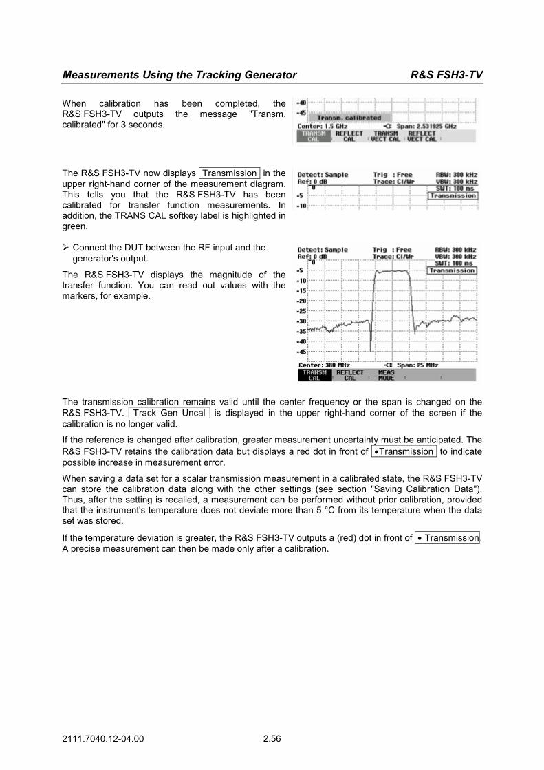
Measurements Using the Tracking Generator R&S FSH3-TV
2111.7040.12-04.00 2.56
When calibration has been completed, the R&S FSH3-TV outputs the message "Transm. calibrated" for 3 seconds.
The R&S FSH3-TV now displays Transmission in the upper right-hand corner of the measurement diagram. This tells you that the R&S FSH3-TV has been calibrated for transfer function measurements. In addition, the TRANS CAL softkey label is highlighted in green. Connect the DUT between the RF input and the
generator's output.
The R&S FSH3-TV displays the magnitude of the transfer function. You can read out values with the markers, for example.
The transmission calibration remains valid until the center frequency or the span is changed on the R&S FSH3-TV. Track Gen Uncal is displayed in the upper right-hand corner of the screen if the calibration is no longer valid.
If the reference is changed after calibration, greater measurement uncertainty must be anticipated. The R&S FSH3-TV retains the calibration data but displays a red dot in front of •Transmission to indicate possible increase in measurement error.
When saving a data set for a scalar transmission measurement in a calibrated state, the R&S FSH3-TV can store the calibration data along with the other settings (see section "Saving Calibration Data"). Thus, after the setting is recalled, a measurement can be performed without prior calibration, provided that the instrument's temperature does not deviate more than 5 °C from its temperature when the data set was stored.
If the temperature deviation is greater, the R&S FSH3-TV outputs a (red) dot in front of • Transmission. A precise measurement can then be made only after a calibration.

R&S FSH3-TV Measurements Using the Tracking Generator
2111.7040.12-04.00 2.57
Measurement of Return Loss
For reflection measurements, the VSWR Bridge and Power Divider R&S FSH-Z2 and a short are needed. The R&S FSH-Z2 is screw-connected to the RF input connector and the generator’s output.
Test port
Control cable
VSWR Bridge andPower DividerR&S FSH-Z2
Connect the control cable of the R&S FSH-Z2 to the power sensor connector of the R&S FSH3-TV.
Connect the RF and generator port of the R&S FSH-Z2 to the RF input and generator output of the R&S FSH3-TV.
The test setup must be calibrated before any measurements are made. This is done with a short and an open at the point were the reflection measurement is to be made. If a cable is to be inserted between the DUT and the bridge, perform the calibration at the measurement end of the cable. Press the MEAS key.
Press the MEASURE softkey.
Using the cursor keys or the rotary knob, select TRACKING GEN from the menu and confirm with the ENTER key or the MEAS softkey.
The R&S FSH3-TV switches on the tracking generator and calls up its softkey menu. Since no calibration has been performed, Track Gen Uncal appears in the upper right-hand corner of the measurement diagram.
Before performing calibration, set the required span because calibration is valid only for the calibrated span. Changing the parameters after calibration invalidates calibration.
Press the FREQ key.
Using the numeric keys, enter the center frequency.
Press the SPAN key.
Using the numeric keys, enter the span.
Alternately, the start and stop frequency can be input using the START and STOP softkeys in the frequency menu. Calibrate the R&S FSH3-TV for the return loss measurement.

Measurements Using the Tracking Generator R&S FSH3-TV
2111.7040.12-04.00 2.58
The following example shows a scalar measurement of return loss. If the option R&S FSH-K2 is installed, measurement must first be switched to scalar. Press the MEAS key.
Press the MEAS MODE softkey.
Using the rotary knob or cursor keys, select SCALAR.
Confirm with the ENTER key or the MEAS MODE softkey.
In the main menu for the tracking generator, press
the REFLECT CAL softkey.
The R&S FSH3-TV prompts you to leave the measurement port open.
Leave the measurement port of the bridge or the cable end open.
Using the CONTINUE softkey, start the OPEN cali-bration.
While calibration is in progress, the R&S FSH3-TV outputs the message "Calibrating OPEN, please wait... ".
After OPEN calibration has been completed, the R&S FSH3-TV prompts you to perform SHORT calibration. Connect a short to the bridge measurement port.
Using CONTINUE, start the SHORT calibration.
While calibration is in progress, the R&S FSH3-TV outputs the message "Calibrating SHORT, please wait... ".
When calibration is over, the R&S FSH3-TV outputs the message "Reflect. calibrated" for 3 seconds.
Reflection is displayed in the upper right-hand corner of the measurement diagram to indicate that the R&S FSH3-TV is calibrated for reflection measurements.
Connect the DUT to the R&S FSH-Z2 measurement port.
The R&S FSH3-TV displays the return loss of the DUT.

R&S FSH3-TV Measurements Using the Tracking Generator
2111.7040.12-04.00 2.59
The transmission calibration remains valid until the R&S FSH3-TV’s center frequency or span is changed. If calibration becomes invalid, the R&S FSH3-TV displays Track Gen Uncal in the upper right-hand corner of the screen.
If the reference is changed after calibration, a larger measurement uncertainty must be anticipated. The R&S FSH3-TV retains the calibration data but places a red dot in front of the • Reflection display to indicate possible increase in measurement uncertainty.
When saving a data set for a scalar reflection measurement in a calibrated state, the R&S FSH3-TV can store the calibration data along with the other settings (see section "Saving Calibration Data"). Thus, after the setting is recalled, a measurement can be performed without prior calibration, provided that the instrument's temperature does not deviate more than 5 °C from its temperature when the data set was stored.
If the temperature deviation is greater, the R&S FSH3-TV outputs a (red) dot in front of • Reflection . A precise measurement can then be made only after a calibration.

Measurements Using the Tracking Generator R&S FSH3-TV
2111.7040.12-04.00 2.60
Performing Distance-To-Fault Measurements
(Only for the R&S FSH3-TV with the installed option R&S FSH-B1 (distance-to-fault measurement) and the VSWR Bridge and Power Divider R&S FSH-Z2)
Control cable
RF connector
VSWR Bridge andPower DividerR&S FSH-Z2 Test port
Generatoroutput
Measurementcable
ShortCable
under test
Connect the control cable of the R&S FSH-Z2 to the power sensor connector of the R&S FSH3-TV.
Connect the RF and generator port of the R&S FSH-Z2 to the RF input and generator output of the R&S FSH3-TV.
Connect the 1 m test cable supplied with option R&S FSH-B1 to the bridge test port.
Note: The 1 m cable must be used. Results are invalid without this cable.
Press the MEAS key.
Press the MEASURE softkey.
Using the cursor keys or rotary knob, select DISTANCE TO FAULT from the menu and confirm with the ENTER key or the MEAS softkey.
The R&S FSH3-TV switches on the distance-to-fault measurement function. The R&S FSH3-TV delivers optimum results if the center frequency is set to the frequency at which the device under test is operated. Press the FREQ key.
Input the center frequency, e.g. frequency of the antenna at the end of the cable under test.

R&S FSH3-TV Measurements Using the Tracking Generator
2111.7040.12-04.00 2.61
To perform distance-to-fault cable measurements, the R&S FSH3-TV needs to be informed about the type of cable and its approximate length. Frequency-dependent cable models can be generated with the supplied R&S FSH View software for Windows and loaded onto the R&S FSH3-TV. The procedure is described in the R&S FSH View manual. The cable parameters for a frequency can also be entered directly.
Selecting a cable model from the list:
Press the MEAS key.
Press the CABLE MODEL softkey.
The R&S FSH3-TV displays the list of loaded cable models.
Using the rotary knob or the cursor keys, select the appropriate cable model.
Using the SELECT softkey, activate the cable model you have selected.
The analyzer returns to the DTF measurement menu and displays the cable used for the measurement in the upper right-hand corner of the screen.
Entering the cable parameters at a specific frequency:
If cables are used that are not listed in cable models stored in the R&S FSH3-TV, it is possible to enter the cable parameters at a specific frequency. It is advisable to use the center frequency of the DTF measurement. Press the MEAS key.
Press the CABLE MODEL softkey.
The R&S FSH3-TV displays the list of loaded cable models (if available).
Press the SELECT USER MOD softkey.
The softkey is highlighted in green to indicate that a user-specific cable model has been chosen.
The cable model is defined with the DEFINE USER MOD softkey.
Press the DEFINE USER MOD softkey.
The R&S FSH3-TV opens a submenu for defining the FREQUENCY, the VELOCITY FACTOR and the ATTENUATION.
Using the rotary knob or the cursor keys, select the appropriate parameter from the submenu and press the ENTER key.
Enter the value (e. g. velocity factor) for the cable used.
Confirm with the ENTER key.
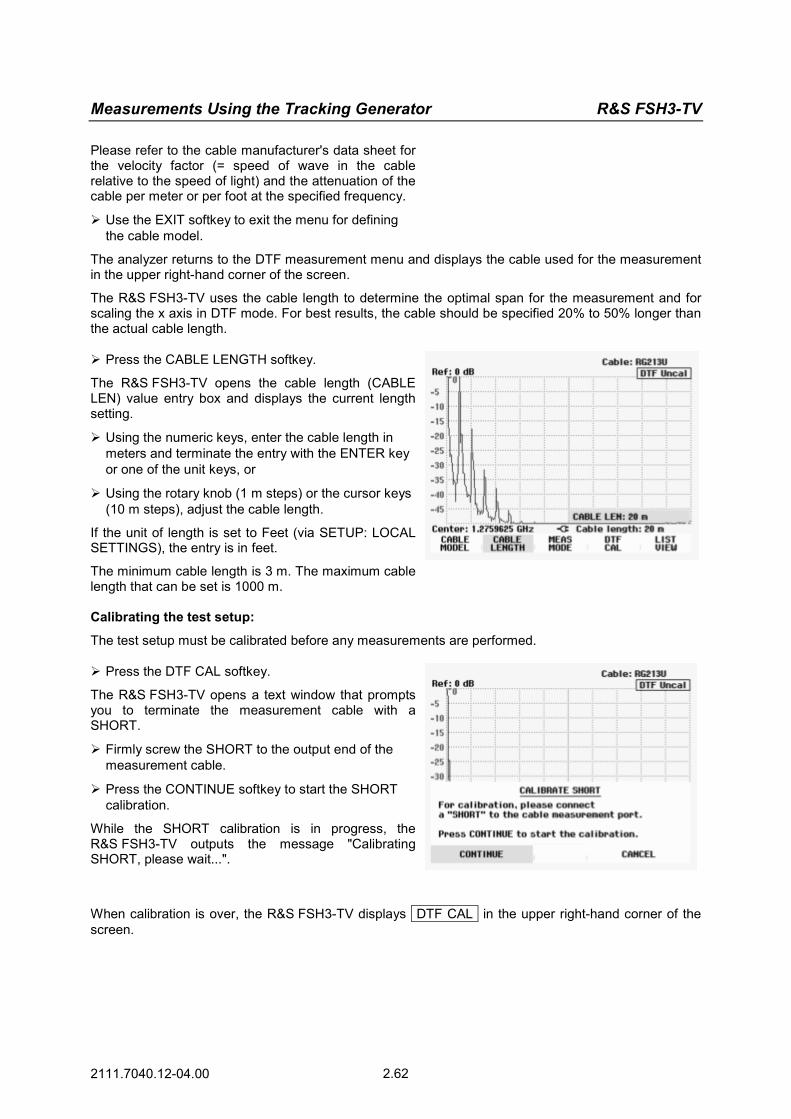
Measurements Using the Tracking Generator R&S FSH3-TV
2111.7040.12-04.00 2.62
Please refer to the cable manufacturer's data sheet for the velocity factor (= speed of wave in the cable relative to the speed of light) and the attenuation of the cable per meter or per foot at the specified frequency.
Use the EXIT softkey to exit the menu for defining the cable model.
The analyzer returns to the DTF measurement menu and displays the cable used for the measurement in the upper right-hand corner of the screen.
The R&S FSH3-TV uses the cable length to determine the optimal span for the measurement and for scaling the x axis in DTF mode. For best results, the cable should be specified 20% to 50% longer than the actual cable length. Press the CABLE LENGTH softkey.
The R&S FSH3-TV opens the cable length (CABLE LEN) value entry box and displays the current length setting.
Using the numeric keys, enter the cable length in meters and terminate the entry with the ENTER key or one of the unit keys, or
Using the rotary knob (1 m steps) or the cursor keys (10 m steps), adjust the cable length.
If the unit of length is set to Feet (via SETUP: LOCAL SETTINGS), the entry is in feet.
The minimum cable length is 3 m. The maximum cable length that can be set is 1000 m.
Calibrating the test setup:
The test setup must be calibrated before any measurements are performed. Press the DTF CAL softkey.
The R&S FSH3-TV opens a text window that prompts you to terminate the measurement cable with a SHORT.
Firmly screw the SHORT to the output end of the measurement cable.
Press the CONTINUE softkey to start the SHORT calibration.
While the SHORT calibration is in progress, the R&S FSH3-TV outputs the message "Calibrating SHORT, please wait...".
When calibration is over, the R&S FSH3-TV displays DTF CAL in the upper right-hand corner of the screen.

R&S FSH3-TV Measurements Using the Tracking Generator
2111.7040.12-04.00 2.63
Calibration tip:
The R&S FSH3-TV performs calibration over its entire span. Therefore, recalibration is not necessary after the cable length is changed. The calibration data is stored in the R&S FSH3-TV memory. Thus, the calibration is valid after the operating mode is changed or after the instrument is switched off. For a calibration to remain valid, the instrument temperature must not deviate more than 5°C. If the temperature deviates more than this amount, the R&S FSH3-TV shows a red dot in front of the • DTF display . A new calibration is then necessary.
Unscrew the short from the measurement cable.
Screw the cable under test to the measurement cable.
The R&S FSH3-TV displays the return loss produced in the cable under test versus the distance.
The R&S FSH3-TV can also list any cable faults. It displays the return loss and distance from the measurement plane of all reflections that exceed a definable threshold. Press the LIST VIEW softkey.
The R&S FSH3-TV opens the threshold value entry box and also displays the threshold as a horizontal line across the measurement diagram.
Set the threshold using the cursor keys (5 dB steps), the rotary knob (1 dB steps) or the numeric keys.
Press the ENTER key or the LIST VIEW softkey again.
The R&S FSH3-TV displays a table listing all the return losses that are above the threshold, sorted according to distance from the measurement plane.
To close the list and to return to the graphical display mode, press the EXIT softkey.

Measurements Using the Tracking Generator R&S FSH3-TV
2111.7040.12-04.00 2.64
Press the MARKER key.
The R&S FSH3-TV opens the marker menu and places the distance marker on the largest return loss. The marker readout provides the distance of the reflection from the measurement plane in meters and its return loss.
Change the distance marker by entering a number, adjusting the rotary knob (pixel by pixel) or by using the cursor keys (step = 10 % of the span).
For higher fault resolution, the R&S FSH3-TV offers a zoom function in the position of the marker. The x axis of the display can be extended up to a span of 3 m. Press the MARKER MODE softkey.
Using the rotary knob or the cursor keys, select ZOOM ON from the menu.
Confirm with the ENTER key.
The entry field for the zoom factor is displayed while the R&S FSH3-TV simultaneously expands the x axis by a factor of 2.
Using the rotary knob or the cursor keys, set the zoom factor to the value you want.
The screenshot on the right shows that the fault of the measured cable consists of two transitions. A coupling of approx. 7 cm in length was used to connect two cables.
Disable the zoom function as follows:
Press the MARKER MODE softkey in the MARKER menu.
Using the rotary knob or the cursor keys, select ZOOM OFF from the menu.
Confirm by pressing the ENTER key or by pressing the MARKER MODE softkey again.
Checking the return loss of the cable under test:
Press the MEAS MODE softkey.
Select REFLECTION using the rotary knob or the cursor keys.
Confirm by pressing the MEAS MODE softkey again or by pressing the ENTER key.
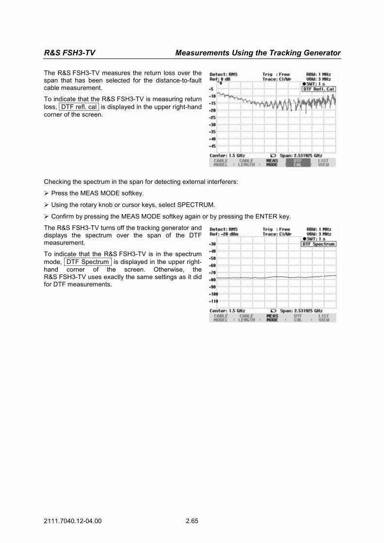
R&S FSH3-TV Measurements Using the Tracking Generator
2111.7040.12-04.00 2.65
The R&S FSH3-TV measures the return loss over the span that has been selected for the distance-to-fault cable measurement.
To indicate that the R&S FSH3-TV is measuring return loss, DTF refl. cal is displayed in the upper right-hand corner of the screen.
Checking the spectrum in the span for detecting external interferers:
Press the MEAS MODE softkey.
Using the rotary knob or cursor keys, select SPECTRUM.
Confirm by pressing the MEAS MODE softkey again or by pressing the ENTER key.
The R&S FSH3-TV turns off the tracking generator and displays the spectrum over the span of the DTF measurement.
To indicate that the R&S FSH3-TV is in the spectrum mode, DTF Spectrum is displayed in the upper right-hand corner of the screen. Otherwise, the R&S FSH3-TV uses exactly the same settings as it did for DTF measurements.

Operation in Receiver Mode R&S FSH3-TV
2111.7040.12-04.00 2.66
Operation in Receiver Mode
(Available only if the option R&S FSH-K3 is installed.) To provide a means of measuring levels at a specific frequency, the R&S FSH3-TV offers the receiver mode as an option (option R&S FSH-K3). With this option, the R&S FSH3-TV functions like a receiver that measures the level at a predefined frequency. Switching on the receiver mode: Press the MEAS key.
Press the MEASURE softkey.
The R&S FSH3-TV opens the menu for measurement functions. Using the cursor keys or the rotary knob, select
RECEIVER and confirm with the ENTER key or MEASURE softkey.
The R&S FSH3-TV activates the receiver mode and measures the level at the specified frequency. The most important settings for the measurement parameters are provided directly in the main menu of the receiver mode, or they can be entered using the corresponding keys.
Setting the frequency:
Press the FREQ softkey in the main menu of the receiver mode.
Using the rotary knob or the cursor keys, adjust the frequency, or, using the numeric keys, enter a new frequency and confirm the entry with the ENTER key.
You can also enter the frequency by using the FREQ key.
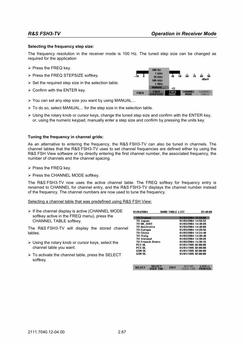
R&S FSH3-TV Operation in Receiver Mode
2111.7040.12-04.00 2.67
Selecting the frequency step size:
The frequency resolution in the receiver mode is 100 Hz. The tuned step size can be changed as required for the application Press the FREQ key.
Press the FREQ STEPSIZE softkey.
Set the required step size in the selection table.
Confirm with the ENTER key.
You can set any step size you want by using MANUAL....
To do so, select MANUAL... for the step size in the selection table.
Using the rotary knob or cursor keys, change the tuned step size and confirm with the ENTER key, or, using the numeric keypad, manually enter a step size and confirm by pressing the units key.
Tuning the frequency in channel grids:
As an alternative to entering the frequency, the R&S FSH3-TV can also be tuned in channels. The channel tables that the R&S FSH3-TV uses to set channel frequencies are defined either by using the R&S FSH View software or by directly entering the first channel number, the associated frequency, the number of channels and the channel spacing. Press the FREQ key.
Press the CHANNEL MODE softkey.
The R&S FSH3-TV now uses the active channel table. The FREQ softkey for frequency entry is renamed to CHANNEL for channel entry, and the R&S FSH3-TV displays the channel number instead of the frequency. The channel numbers are now used to tune the frequency. Selecting a channel table that was predefined using R&S FSH View:
If the channel display is active (CHANNEL MODE softkey active in the FREQ menu), press the CHANNEL TABLE softkey.
The R&S FSH3-TV will display the stored channel tables. Using the rotary knob or cursor keys, select the
channel table you want.
To activate the channel table, press the SELECT softkey.
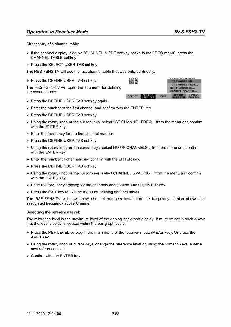
Operation in Receiver Mode R&S FSH3-TV
2111.7040.12-04.00 2.68
Direct entry of a channel table:
If the channel display is active (CHANNEL MODE softkey active in the FREQ menu), press the CHANNEL TABLE softkey.
Press the SELECT USER TAB softkey.
The R&S FSH3-TV will use the last channel table that was entered directly. Press the DEFINE USER TAB softkey.
The R&S FSH3-TV will open the submenu for defining the channel table. Press the DEFINE USER TAB softkey again.
Enter the number of the first channel and confirm with the ENTER key.
Press the DEFINE USER TAB softkey.
Using the rotary knob or the cursor keys, select 1ST CHANNEL FREQ... from the menu and confirm with the ENTER key.
Enter the frequency for the first channel number.
Press the DEFINE USER TAB softkey.
Using the rotary knob or the cursor keys, select NO OF CHANNELS... from the menu and confirm with the ENTER key.
Enter the number of channels and confirm with the ENTER key.
Press the DEFINE USER TAB softkey.
Using the rotary knob or the cursor keys, select CHANNEL SPACING... from the menu and confirm with the ENTER key.
Enter the frequency spacing for the channels and confirm with the ENTER key.
Press the EXIT key to exit the menu for defining channel tables.
The R&S FSH3-TV will now show channel numbers instead of the frequency. It also shows the associated frequency above Channel. Selecting the reference level:
The reference level is the maximum level of the analog bar-graph display. It must be set in such a way that the level display is located within the bar-graph scale. Press the REF LEVEL softkey in the main menu of the receiver mode (MEAS key). Or press the
AMPT key.
Using the rotary knob or cursor keys, change the reference level or, using the numeric keys, enter a new reference level.
Confirm with the ENTER key.

R&S FSH3-TV Operation in Receiver Mode
2111.7040.12-04.00 2.69
Selecting the bandwidth:
The receiver mode provides the same bandwidths as in analyzer operation. In addition, the three bandwidths 200 Hz, 9 kHz and 120 kHz are available for EMI measurements in accordance with CISPR16. Press the BW key
Using the rotary knob or cursor keys, enter the bandwidth you want and confirm by pressing the unit key.
For input of a CISPR bandwidth press the softkey CISPR BW.
Using the rotary knob or cursor keys, change the bandwidth and confirm with the ENTER key, or, using the numeric keypad, manually enter bandwidth and confirm by pressing the unit key.
According to CISPR16 the bandwidth is connected to the frequency. The R&S FSH3-TV allows to couple the bandwidth to the set frequency automatically: Press the softkey AUTO CISPPR BW.
The R&S FSH3-TV uses the suitable bandwidth dependent on the set frequency. Setting the detector:
The receiver mode of the R&S FSH3-TV offers a peak detector, average detector, RMS detector and quasi-peak detector. Set the detector either from the main menu of the receiver mode or by using the TRACE key. Press the DETECTOR softkey in the main menu of
the receiver mode, or press first the TRACE key and then the DETECTOR softkey
Using the rotary knob or cursor keys, select a detector from the selection list.
Press the ENTER softkey.
Setting the measurement time:
The measurement time is the amount of time during which the R&S FSH3-TV collects measured values and compiles them into a display result for the selected detector. Press the MEAS TIME softkey in the main menu of the receiver mode, or press the SWEEP key.
Using the rotary knob or cursor keys, adjust the measurement time, or, using the numeric keys, enter a new measurement time and confirm with the unit.
Note: If the quasi-peak detector is selected, the selected measurement time must be larger than 100 ms in order to ensure that fluctuating or pulse-like signals are measured correctly.

Operation in Receiver Mode R&S FSH3-TV
2111.7040.12-04.00 2.70
Scanning in the receiver mode:
In the receiver mode, the R&S FSH3-TV can scan across a defined number of frequencies and graphically display the results. It performs a measurement at each frequency for the defined measurement time. Press the SPAN softkey.
Press the FREQ SCAN softkey.
The R&S FSH3-TV switches to the scan mode and displays the measurement levels at the individual frequencies as vertical lines. Press the SCAN START softkey.
Enter the start frequency for the scan.
Press the SCAN STOP softkey.
Enter the stop frequency for the scan.
Press the SCAN STEP softkey.
Enter the step size for the scan.
It is also possible to scan the frequencies of a channel table. This requires activating a channel table as follows: Press the FREQ softkey.
Press the CHANNEL MODE softkey.
The R&S FSH3-TV now performs a measurement at the frequencies of the channel table.
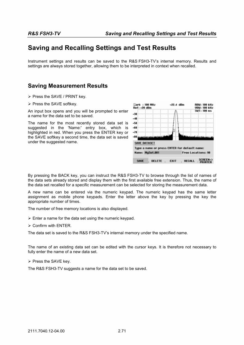
R&S FSH3-TV Saving and Recalling Settings and Test Results
2111.7040.12-04.00 2.71
Saving and Recalling Settings and Test Results
Instrument settings and results can be saved to the R&S FSH3-TV’s internal memory. Results and settings are always stored together, allowing them to be interpreted in context when recalled.
Saving Measurement Results
Press the SAVE / PRINT key.
Press the SAVE softkey.
An input box opens and you will be prompted to enter a name for the data set to be saved.
The name for the most recently stored data set is suggested in the 'Name:' entry box, which is highlighted in red. When you press the ENTER key or the SAVE softkey a second time, the data set is saved under the suggested name.
By pressing the BACK key, you can instruct the R&S FSH3-TV to browse through the list of names of the data sets already stored and display them with the first available free extension. Thus, the name of the data set recalled for a specific measurement can be selected for storing the measurement data.
A new name can be entered via the numeric keypad. The numeric keypad has the same letter assignment as mobile phone keypads. Enter the letter above the key by pressing the key the appropriate number of times.
The number of free memory locations is also displayed. Enter a name for the data set using the numeric keypad.
Confirm with ENTER.
The data set is saved to the R&S FSH3-TV’s internal memory under the specified name.
The name of an existing data set can be edited with the cursor keys. It is therefore not necessary to fully enter the name of a new data set. Press the SAVE key.
The R&S FSH3-TV suggests a name for the data set to be saved.
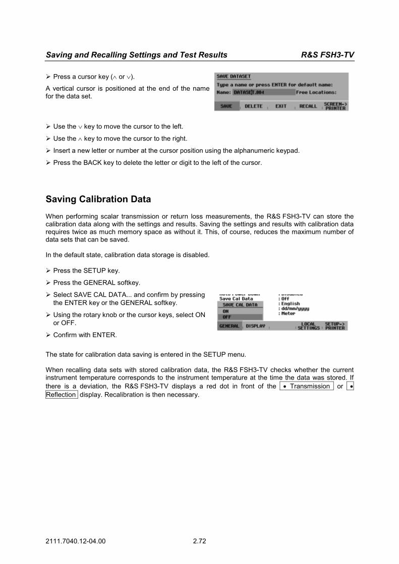
Saving and Recalling Settings and Test Results R&S FSH3-TV
2111.7040.12-04.00 2.72
Press a cursor key (∧ or ∨).
A vertical cursor is positioned at the end of the name for the data set.
Use the ∨ key to move the cursor to the left.
Use the ∧ key to move the cursor to the right.
Insert a new letter or number at the cursor position using the alphanumeric keypad.
Press the BACK key to delete the letter or digit to the left of the cursor.
Saving Calibration Data
When performing scalar transmission or return loss measurements, the R&S FSH3-TV can store the calibration data along with the settings and results. Saving the settings and results with calibration data requires twice as much memory space as without it. This, of course, reduces the maximum number of data sets that can be saved. In the default state, calibration data storage is disabled. Press the SETUP key.
Press the GENERAL softkey.
Select SAVE CAL DATA... and confirm by pressing the ENTER key or the GENERAL softkey.
Using the rotary knob or the cursor keys, select ON or OFF.
Confirm with ENTER.
The state for calibration data saving is entered in the SETUP menu. When recalling data sets with stored calibration data, the R&S FSH3-TV checks whether the current instrument temperature corresponds to the instrument temperature at the time the data was stored. If there is a deviation, the R&S FSH3-TV displays a red dot in front of the • Transmission or •Reflection display. Recalibration is then necessary.

R&S FSH3-TV Saving and Recalling Settings and Test Results
2111.7040.12-04.00 2.73
Recalling Measurement Results
Use the R&S FSH3-TV’s recall function to review previously saved measurement results and settings. Press the SAVE / PRINT key.
Press the RECALL softkey.
A list of all saved data sets opens. The red selection bar marks the last data set to be saved. Select a data set from the list using the rotary knob.
Confirm your selection by pressing the RECALL softkey.
The selected data set is displayed on the screen, but the R&S FSH3-TV is not set to the settings in the data set. You can now check the data set before its settings are activated.
The name of the selected data set is displayed at the lower left-hand corner of the screen. Using the rotary knob or the cursor keys, you can scroll through all the available data sets. The settings and results for each data set are displayed. You now have the following options: Press the STATUS key to see all the instrument
settings in the selected data set. When you press the STATUS key again, the R&S FSH3-TV returns to the graphical display.
Press the ACTIVATE softkey to load the data set.
Press the EXIT softkey to display the list of data sets again. Press EXIT a second time and the R&S FSH3-TV returns to its previous settings without loading a data set.
Press SCREEN->PRINTER to send the displayed data set to a printer.
Pressing the ACTIVATE softkey transfers the stored trace to the R&S FSH3-TV's trace memory. The current trace can be compared with the stored one by switching on the trace memory.
Saving and Recalling Settings and Test Results R&S FSH3-TV
2111.7040.12-04.00 2.74
Press the TRACE key.
Press the SHOW MEMORY softkey.
The R&S FSH3-TV displays the stored trace in white and the current trace in yellow.
Note: The trace is in the R&S FSH3-TV's trace memory. The level and frequency values are displayed correctly only if neither the instrument's frequency setting nor its level setting has been changed.

R&S FSH3-TV Printing Out Measurement Results
2111.7040.12-04.00 2.75
Printing Out Measurement Results
The R&S FSH3-TV can send screenshots to a printer equipped with a serial interface. The type of printer and the baud rate of the serial interface can be defined in the setup menu (SETUP key) by using the GENERAL softkey and selecting 'PRINTER BAUD...' and 'PRINTER TYPE...' from the menu. For printers with a parallel interface, a serial/parallel converter (R&S FSH-Z22) is available. Printer with serial interface:
Connect the printer to the optical interface of the R&S FSH3-TV using the RS-232-C optical interface cable (R&S FSH-Z34).
Printer with parallel interface:
Connect the RS-232-C optical interface cable (R&S FSH-Z34) to the Serial/Parallel Converter R&S FSH-Z22.
Connect the R&S FSH-Z22 parallel interface to the printer.
Switch on the Serial/Parallel Converter R&S FSH-Z22
Operating the R&S FSH3-TV:
Press the SAVE / PRINT key.
The SAVE/PRINT menu with the option for printing out a screenshot to a printer opens. Press the SCREEN->PRINTER softkey.
The R&S FSH3-TV starts printing out the screenshot to a printer.