TURNING AND LIVE TOOL FUNCTIONS · •The G code used to call circular interpolation is G02 or G03,...
152
OKUMA LATHE PROGRAMMING TURNING AND LIVE TOOL FUNCTIONS
Transcript of TURNING AND LIVE TOOL FUNCTIONS · •The G code used to call circular interpolation is G02 or G03,...

OKUMA LATHE PROGRAMMING
TURNING AND LIVE TOOL FUNCTIONS

INTRO/BASIC OSP LATHE PROGRAMMING
PROGRAMMING CODES IN THE ORDER WHICH THEY APPEAR IN THIS MANUAL
COMMON POSITIONING CODES COMMON NON POSITION CODES & FUNCTIONS G40/G41/G42: TOOL NOSE COMP G73/G74/G77: GROOVING, DRILLING, AND TAPPING CYCLES G71: THREADING CYCLES G80-G87: LAP CYCLES SPEEDS AND FEEDS TURNING DRAWINGS LIVE TOOL DRILLING CYCLES Y AXIS PROGRAMMING TORQUE SKIP CONTOUR GENERATION COORDINATE CONVERSION LIVE TOOL DRAWINGS G-CODE AND M-CODE TABLE CLASS EVALUATION

5238-E P-24SECTION 3 MATH FUNCTIONS
SECTION 3 MATH FUNCTIONS
1. Positioning (G00)[Function]Each axis moves independently from the actual position to the target position at its own rapidfeedrate. At the start and end of axis movement, it is automatically accelerated and decelerated.[Programming format]G00 X__ Z__ C__
[Details]
• In G00 mode positioning, execution of the commands in the next block begins only after thepositioning at the target position given in the current block is completed.
• Non-linear interpolation mode:The axes move independently of each other at a rapid feedrate. Therefore, the resultant toolpath is not always a straight line.
LE33013R0600500010001
[Supplement]
2. Linear Interpolation (G01)[Function]The G01 command specifies the axes to move directly from the current position to the specifiedcoordinate values at the specified feedrate.[Programming format]G01 X__ Z__ C__ F__
X/Z/C : Indicates the target position for positioning operation.
The rapid feedrates of each axis are set by the machine specifications.
X, Z, C : Target point (end point)F : Feedrate.
The specified value remains effective until updated by another value.
Target position
Actual position
X
Z

5238-E P-26SECTION 3 MATH FUNCTIONS
3. Circular Interpolation (G02, G03)[Function]Circular interpolation can be used to generate a cutting path which follows an arc. [Programming format]
LE33013R0600500030001
[Details]
• The two directions of rotation, clockwise and counterclockwise, are defined when viewing the X-Z plane from the positive direction of the axis orthogonal to the plane in the right-handorthogonal coordinate system.
LE33013R0600500030002
• The end point of an arc is defined as an absolute value or an incremental value depending onthe G90/G91 selection.
• The center of an arc is expressed by I and K, which correspond to X and Z respectively. That is,I expresses the X coordinate value and K the Z coordinate value of the center of the arc inreference to the starting point of the arc.
G02 : Direction of rotation : Sets clockwise rotationG03 : Direction of rotation : Sets counterclockwise rotationX, Z : G90 mode : Set the end point in the program coordinate systemX, Z : G91 mode : Sets the end point in reference to the starting point
(values should include signs)I, K : Set the distance of the center of the arc from the starting point (values should include
signs)L : Sets the radius of the arcF : Sets the feedrate
G02(G03)
X__ Z__ F__L__
I__ K__{ }
X
G03
G02Z

5238-E P-27SECTION 3 MATH FUNCTIONS
For I and K, signed incremental values are used regardless of the mode, G90 or G91.
LE33013R0600500030003
Determining Sign and Numeric Value of I and K Words:See the figure below. Assume the coordinate system has its origin at the arc start point. Draw aright-angled triangle taking the segment connecting the arc center and arc start point as thehypotenuse. The length of side (b), parallel to the Z-axis, is the value of the K word and that ofside (c), parallel to the X-axis, is the value of the I word.Concerning the sign of these words, when side (b) lies in the positive direction of the assumedcoordinate system, it is taken as a positive value and when it lies in the negative direction, it isnegative. The sign of I words is determined in a similar way. That is, when side (c) lies in thepositive direction of the coordinate system, the I word has a positive value and when it lies inthe negative direction, the I word has a negative value.
LE33013R0600500030004
X(I)Z1
X1 φ
Arc center
Arc end point
R
K1
Z(K)
Arc start point
G02: Both I and K values are positive Z1, X1 indicate the coordinate values of the arc end point.
I
X(I)Z1
X1Arccenter
Arc end point
Arc start point
K
R
Z(K)
G03: Both I and K values are positive Z1, X1 indicate the coordinate values of the arc end point
φ
I
X-axis
Z-axis
Arc start point
Arc center
ID cutting
OD cutting
I +
I +
I -
I -
K +K -
K -
K -
K -
I - K -
I + K -
(a)(c)
(b)

5238-E P-28SECTION 3 MATH FUNCTIONS
• It is possible to execute circular interpolation by specifying the X and Z coordinate values of thetarget point and the radius of the arc instead of using I and K commands.
[Supplement]
In direct radius command programming, the control automatically calculates the coordinates of thecenter of the arc, I and K, from the programmed radius L and the coordinates of the end point, X andZ, to perform circular interpolation.The program for the example in the figure to the right is as follows.Program:
LE33013R0600500030005
• The feedrate during circular interpolation is the feedrate component tangential to the arc.
• The G code used to call circular interpolation is G02 or G03, as when using I and K.• The radius of the arc is expressed by an L word which must have a positive value.• A block containing an L word without a K or I word is an arc radius command.• When expressing an arc by its radius, the commands must contain both X and Z words.
If either of them is omitted, an alarm results.• If an L word is specified in a block containing I and/or K word, an alarm results.• If the distance from the current position to the target point (end point) is larger than two times
the specified radius, an alarm results since circular interpolation cannot be performed.• In direct arc command programming, one arc command yields two arcs; one with central angle
less than 180, and another larger than 180. The arc with central angle less than 180 isselected.To obtain the arc whose central angle is greater than 180, specify "CALRG" in the blockcommanding circular interpolation.
• The direct radius command programming is effective in:LAPTool nose radius compensation modeSubprograms
• Incremental programming mode (G91)
+X
+Z
N2
(Z2,X2) N1(Z1,X1)
Center
r rN1 G01 X1 Z1 F1
N2 G03 X2 Z2 LrWith the commands above, the arc indicated by a thick solid line is obtained.
To move the tool along the arc indicated by dashed lines, program as follows:N1 G01 X1 Z1 F1
N2 G03 CALRG X2 Z2 Lr

5238-E P-30SECTION 3 MATH FUNCTIONS
4. Automatic ChamferingWhen cutting a workpiece, it is often necessary to chamfer a sharp edge (either straight-linechamfering (C-chamfering) or rounding). Although such chamfering can be accomplished usingconventional interpolation commands (G01, G02, G03), the automatic chamfering function permitschamfering to be done with a simple program.For chamfering at any required angle, the automatic any-angle chamfering function should be used.To use the automatic chamfering function, set "1" for optional parameter (OTHER FUNCTION 1)Auto. any-angle chamfering. If the automatic any-angle chamfering function is required, set "any-angle chamfering" for this parameter.
4-1. C-chamfering (G75)
LE33013R0600500050001
To cut the contour shown above along the points A, B, D and E, program as follows:G75 G01 X120 L-5 F∆∆ CRafter positioning the cutting tool at point A.With the commands above, the cutting tool moves from point A to B and then to D, thusautomatically chamfering the corner at 45 with a size of 5 mm.
When the coordinates of point E are commanded, the cutting tool moves from Point D to Point E.[Details]
• G75 is effective only in the G01 mode. If G75 is specified in another mode, it causes an alarm.
• G75 is non-modal and active only in the commanded block.
• If the axis movement dimension specified in the block calling for automatic chamfering (A - C inthe figure above) is smaller than the absolute value of the L word (B - C in the figure above), analarm results.
• If the axis movement dimensions specified in the block calling for automatic chamfering arezero both for X and Z, or if neither the X nor the Z value is zero in such a block, an alarm occurs.The block calling for the automatic chamfering mode can contain only one dimension word,either X or Z.
G75 : Specifies C-chamferingX120 : X coordinate of Point CL-5 : Size of chamfered face
The sign is determined by the direction of axis movement;"+" when the Z-axis (X-axis) moves in the positive direction after X-axis (Z-axis) motion."-" when the Z-axis (X-axis) moves in the negative direction after X-axis (Z-axis) motion.
+X
+Z
(X120.00, Z50.00) (X120.00, Z115.00)
C (X120.00, Z120.00)
B (X110.00, Z120.00)
A (X50.00, Z120.00)
E D
5C

5238-E P-31SECTION 3 MATH FUNCTIONS
• The automatic chamfering program is effective in:LAPTool nose radius compensation mode
[Program example]
LE33013R0600500050002
40.0010.00
60.0090.00
5C 4C
3C2C
160.
00φ
100.
00φ
60.0
0φ
:
:
N101
N102
N103
N104
N105
N106
:
:
G01
G75
G75
G75
G75
X60
X100
X160
Z92
Z60
Z40
Z10
F0.1
F0.05 L3
L-2
L4
L-5

5238-E P-32SECTION 3 MATH FUNCTIONS
4-2. Rounding (G76)
LE33013R0600500060001
To cut the contour shown above along the points A, B, D and E, program as follows:G76 G01 X120 L-5 F∆∆ CRafter positioning the cutting tool at point A.With the commands above, the cutting tool moves from point A to B and then to D, thusautomatically rounding the corner to a radius of 5 mm.
When the coordinates of point E are commanded, the cutting tool moves from point D to point E.[Details]
• G76 is effective only in the G01 mode. If G76 is specified in a mode other than G01, an alarmoccurs.
• G76 is non-modal and active only in the commanded block.
• The rounding describes a 1/4 circle with the radius specified by an L word.
• If the axis movement dimension specified in the block calling for automatic chamfering (A - C inthe figure above) is smaller than the absolute value of the L word (B - C in the figure above), analarm results.
• If the axis movement dimensions specified in the block calling for automatic chamfering arezero both for X and Z, or if neither X nor Z value is zero in such a block, an alarm occurs.The block calling for automatic chamfering mode can contain only one dimension word, either Xor Z.
• The automatic chamfering program is effective in:LAPTool nose radius compensation mode
G76 : Specifies rounding of a cornerX120 : X coordinate of Point CL-5 : Radius of rounding circle
The sign is determined by the direction of axis movement;"+" when the Z-axis (X-axis) moves in the positive direction after the X-axis (Z-axis) motion."-" when the Z-axis (X-axis) moves in the negative direction after the X-axis (Z-axis) motion.
+X
B (X110.00, Z120.00)
A (X50.00, Z120.00)
C (X120.00, Z120.00)
(X120.00, Z115.00)(X120.00, Z50.00)
+Z
5R
E D

5238-E P-33SECTION 3 MATH FUNCTIONS
[Program Example]
LE33013R0600500060002
40.00
10.00
60.00
90.00
5R
4R
3R2R
160.
00φ
100.
00φ
60.0
0φN101
N102
N103
N104
N105
N106
G01
G76
G76
G76
G76
X60
X100
X160
Z92
Z60
Z40
Z10
F0.1
F0.05 L3
L-2
L4
L-5

5238-E P-34SECTION 3 MATH FUNCTIONS
4-3. Automatic Any-Angle Chamfering
When cutting a workpiece, it is often necessary to chamfer the sharp (C-chamfer or R-chamfer)corners and edges. If chamfering is required on edges having an angle other than 90°,programming chamfering using G01, G02 and G03 commands is not easy. This automaticchamfering function can program chamfering easily.[Programming Examples]
(1) C-Chamfering (G75)
LE33013R0600500070001
With the program above, the cutting tool moves from point A to point J in the sequence A, B, D,E, G, H, I and J, thus accomplishing chamfering of B-D, E-G and H-I.
[Supplement]
Angle commands (A) are designated in reference to the Z-axis.
+X
+Z
J (X100, Z30) I (X100, Z72.453)
H (X89.608, Z81.453)
(X68.660, Z87,5) G(X60, Z114)
(X60, Z90) F C (X60, Z120)
B (X48, Z120)
A (X20, Z120)
(X60, Z95)
D
6C
5C
6C
120˚
E
N100N110N120N130N140
G00G75G75G75
G01
A120
X20X60
X100
Z120
Z90
Z30
L6L5L6
F∆∆∆
⋅⋅⋅⋅
⋅⋅⋅⋅

5238-E P-35SECTION 3 MATH FUNCTIONS
(2) R-Chamfering (G76)
LE33013R0600500070002
With the program above, the cutting tool moves from point A to point J in the sequence A, B, D,E, G, H, I and J, thus accomplishing chamfering of B-D, E-G, and H-I.
[Supplement]
With the C-chamfer function, axis movements in the G00, G01, G34 and G35 modes can bedesignated by simply entering an angle command A without X and/or Z coordinate data.
Example:
LE33013R0600500070003
(X1, Z1) should not be designated; it is automatically generated in the NC.
+X
(X70, Z87.113)
(X60, Z90)
(X60, Z95.774)
I (X100, Z73.884)H (X92, Z80.762)
(X60, Z114)D C (X60, Z120)
A (X20, Z120)
B (X48, Z120)
10R8R
6R
120˚
J (X100, Z30)
G
FE
+Z
N100N110N120N130N140
G00G76G76G76
G01
A120
X20X60
X100
Z120
Z90
Z30
L6L10L8
F∆∆
⋅⋅⋅⋅
⋅⋅⋅⋅
(X2, Z2)
(X0, Z0)
(X1, Z1)
-150˚
-160˚
G00
G01
X0
A-150
X2
Z0
Z2
F∆A-160
CR
CR
CR

5238-E P-40SECTION 4 PREPARATORY FUNCTIONS
SECTION 4 PREPARATORY FUNCTIONSG codes are used to specify particular functions which are to be executed in individual blocks. Every G codeconsists of the address "G" plus a 3-digit number (00 to 399)
• Effective G Code Ranges
LE33013R0600600010001
• Special G CodesThe mnemonic codes of subprogram calls and branch instructions are called special G codes. Everyspecial G code must be specified at the beginning of a block, not part way through a block. Note,however, that a "/" (block delete) and a sequence name may be placed before a special G code.
1. Dwell (G04)[Function]If dwell is specified, execution of the next block is suspended for the specified length of time after thecompletion of the preceding block.[Programming format]G04 F__
F : Specify the length of time for which the execution of a program is suspended.The unit of command values is determined by the selected programming unit system.For details, refer to the optional parameter (unit system).The maximum allowable length of a dwell period is 9999.99 seconds.
One-shot : A one-shot G code is effective only in a specified block and is automatically canceled when program execution moves to the next block.Modal : A modal G code is effective until it is changed to another G code in the same group.

5238-E P-41SECTION 4 PREPARATORY FUNCTIONS
2. Zero Shift/Max. Spindle Speed Set (G50)
2-1. Zero Shift
[Function]With the G50 code, zero offset value is automatically calculated and zero setting is carried outaccording to the calculated value.This feature is effective when cutting a workpiece on which the same contour is repeated.[Programming format]G50 X__ Z__ C__
[Details]For the present X- and Z-axis position, the coordinate value specified following G50 are assigned.[Program]
LE33013R0600600030001
With the program above, the axes are positioned to the coordinate point (X0, Z0) by the commandsin block N004 first. When the commands in N005 are executed, the coordinate system is re-established so that (X0, Z0), where the axes have been positioned, now has the coordinate values(X1, Z1) which are specified following G50.This program shifts the origin of the coordinate system:X = X0 - X1Z = Z0 - Z1Provided X0 = 100 mm and X1 = 200 mm, zero offset amount is calculated as;100 - 200 = -100 mmThis amount can be checked on the screen.Dimension words in sequences N006 and after that are all referenced to the origin newlyestablished by the commands in N005.
[Supplement]
X/Z/C : Specify the coordinate value to be taken as the actual position data after zero shift.
1) Axes not specified in the block containing G50 are not subject to zero offset.2) G50 is non-modal and active only in the programmed block. (Zero offset is calculated only in
the G50 block. All dimension words after that block are referenced to the shifted new origin.)3) When the control is reset, all zero set data are cleared and the initial zero offset data become
effective.4) No tool offset number entry is allowed in the block containing the G50 code.
N004
N005
N006
G00
G50
G00
X0
X1
X2
Z0
Z1
Z2

5238-E P-42SECTION 4 PREPARATORY FUNCTIONS
2-2. Max. Spindle Speed Set
[Function]Sometimes the spindle speed must be clamped at a certain speed due to the restrictions on theallowable speed of a chuck, influence of centrifugal force on workpiece gripping force, imbalance ofa workpiece, or other factors. This feature allows a maximum spindle speed to be set in such cases.[Programming format]G50 S__
[Details]Once set, the specified speed remains effective until another spindle speed is specified.
3. Droop Control (G64, G65)[Function]The axis movements of the machine are controlled by a servo system in which the axis moves toeliminate the lag (termed DIFF or droop) between the actual tool position and the commandedcoordinate.Due to existence of DIFF (servo error), the actual path does not precisely agree with thecommanded tool path when cutting a sharp corner, as illustrated below:The Droop Corner Control Function is provided to eliminate or reduce such path tracing error toacceptable amounts by stopping the generation of functions (pulses) at the corner until the DIFFreaches the preset permissible droop amount.
LE33013R0600600050001
[Programming format]
• Droop corner control OFF commandG64(The control is placed in the G64 mode when G64 is turned ON.)
• Droop corner control ON commandG65
[Details]
• With G65 presented, axis movement commands in G00, G01, G02, G03, G31, G32, G33, G34,and G35 mode are completed after the DIFF amount becomes smaller than the permissibledroop amount.
• The permissible droop amount can be set within a range from 0 to 1.000 mm for a userparameter at the NC operation panel.
S : Specify the maximum spindle speed.
Droop
Programmed tool path
Actual tool path

5238-E P-43SECTION 4 PREPARATORY FUNCTIONS
4. Feed Per Revolution (G95)[Function]Specify G95 to control tool movement (feedrate) in terms of "distance per spindle revolution" forturning operations.[Programming format]G95 F__
[Details]
• The allowable maximum feedrate depends on the machine specifications.
• On turning on the power, and after reset, the feed per revolution mode is selected.
5. Feed Per Minute (G94)[Function]Specify G94 to control tool movement (feedrate) in terms of "distance per minute" for turningoperations.[Programming format]G94 F__
[Details]
• The allowable maximum feedrate depends on the machine specifications.
F : Specify movement distance per spindle revolution.The unit of setting is determined according to the setting for the optional parameter (UNIT)
F : Specify tool movement distance per minute.The unit of setting is determined according to the setting for the optional parameter (UNIT)

5238-E P-44SECTION 4 PREPARATORY FUNCTIONS
6. Constant Speed Control (G96/G97)[Function]When the constant speed cutting function is selected, cutting at a constant cutting speed is possible.This feature can reduce cutting time and also assure stable finish in end face cutting operations.
Constant Speed Cutting Command[Programming format]G96 S__
Canceling Constant Speed Cutting[Programming format]G97 S__
[Program Example]
LE33013R0600600080001
[Supplement]
S : Set the cutting speed (setting unit: m/min)
S : Set the spindle speed to be used after canceling the constant speed cutting mode.
1) If the spindle speed exceeds the maximum or minimum speed allowed within the rangeselected by an M code while in the constant speed cutting mode, it is fixed at the allowedmaximum or minimum speed automatically; the LIMIT indication light on the operation panelgoes on.
2) If the X-axis is moved a large distance at the rapid traverse rate while in the constant speedcutting mode, for example from the turret indexing position toward the workpiece or vice versa,there will be sudden changes in the rotational speed which, depending on the chucking method,could be dangerous. Therefore, the constant speed cutting mode must be cancelled before commanding positioningof the cutting tool near the workpiece, return of the tool to the turret indexing position, or anyother operation that causes large X-axis travel.
3) A block containing G96 or G97 must contain an S word.4) Thread cutting programs cannot be executed in the G96 constant speed cutting mode.5) To activate the constant speed cutting mode on turret B, specify G111 with G96. To restore
the constant speed cutting mode to turret A, specify G110.6) To execute the commands over two blocks continuously with control in the constant speed
cutting mode without waiting for the spindle speed arrived signal, specify M61. To cancel this,specify M60.
N ΟΟΟ G96 S100⋅⋅⋅⋅⋅⋅⋅All cutting following this block is executed at a cutting speed of 100 m/min.
N ΟΟΟ G97 S500⋅⋅⋅⋅⋅⋅⋅After this block, cutting is carried out at a spindle speed of 500 min-1.

5238-E P-45SECTION 5 S, T, AND M FUNCTIONS
SECTION 5 S, T, AND M FUNCTIONSThis section describes the S, SB, T, and M codes that specify the necessary machine operations other thanaxis movement commands.
One block can contain: one S code, one T code, and eight M codes.
1. S Functions (Spindle Functions)[Function]By specifying number following address S, spindle speed can be specified.[Programming format]S__[Details]
• S command range: 0 to 65535
• If there is an S command and an axis move command in the same block, the S command isexecuted first and then the axis move command is executed.
• The S command will not be canceled when the NC is reset, however, it will be set to 0 when thepower supply is turned off.
• To rotate the spindle, the S command must be specified in a block that precedes the blockcontaining the spindle start command or in the same block.
[Supplement]
2. SB Code Function[Function]M-tool spindle speed is specified using address SB.[Programming format]SB = __If an address consisting of two or more characters is used, an equal symbol must be entered beforea numeric value.
• SB command range: 0 to 65535
• M-tool spindle rotation (forward, reverse) and stop are specified by M codes.
• The SB command will not be canceled when the NC is reset, however, it will be set to 0 whenthe power supply is turned off.
S : Spindle speedSB : Spindle speed of M-tool spindleT : Tool number, tool offset number, tool nose radius compensation numberM : Miscellaneous function to control machine operation
1) For a machine equipped with the transmission gears, the required gear range should beselected with the corresponding M code.
2) Spindle rotation (forward, reverse) and stop are specified by M codes.

5238-E P-46SECTION 5 S, T, AND M FUNCTIONS
• To rotate the M-tool spindle, the SB command must be specified in a block that precedes theblock containing the M-tool spindle start command or in the same block.
[Supplement]
3. T Functions (Tool Functions)[Function]By specifying a 4-digit number (NC without tool nose radius compensation function) or a 6-digitnumber (NC with tool nose radius compensation function) following address T, tool number, tooloffset number, and tool nose radius compensation number are indicated.[Programming format]
LE33013R0600700040001
The setting ranges for nose radius compensation numbers and tool compensation numbers are asfollows:
(1) For offset 32-set specification
• Tool offset number: 00 to 32
• Tool nose radius compensation number: 00 to 32(if tool nose radius compensation function is supported.)
(2) For offset 64-set specification
• Tool offset number: 00 to 64
• Tool nose radius compensation number: 00 to 64(if tool nose radius compensation function is supported.)
(3) For offset 96-set specification
• Tool offset number: 00 to 96
• Tool nose radius compensation number: 00 to 96(if tool nose radius compensation function is supported.)
[Details]If there is a T command and an axis move command in the same block, the T command is executedfirst and then the axis move command is executed.
[Supplement]
1) For the machine equipped with the transmission gears for driving the M-tool spindle, therequired gear range should be selected by a corresponding M code.
2) M-tool spindle rotation (forward, reverse) and stop are specified by M codes.
The construction of the turret and its direction of rotation (forward, reverse, shorter-path) varyaccording to the machine specifications.
TΟΟ∆∆
ΟΟ : Tool nose radius compensation number
∆∆ : Tool number (00 to 99, assuming maximum number of turret stations)
: Tool offset number

5238-E P-56SECTION 6 OFFSET FUNCTION
SECTION 6 OFFSET FUNCTION
1. Tool Nose Radius Compensation Function (G40, G41, G42)
1-1. General Description
The tool tip point radius of most cutting tools used in turning operation is the cause ofinconsistencies between the designated tool paths and the actually finished workpiece contour.With the tool radius compensation function, such geometric error is automatically compensated forby simple programming.
1-2. Tool Nose Radius Compensation for Turning Operations
Tool Offset and Nose Radius CompensationIn turning operations, various types and different shapes of tools are used to finish one workpiece.ID cutting tools, OD cutting tools, rough cut tools, finish cut tools, drills, etc. Accordingly, the toolnose radius compensation function has to be activated simultaneously with the tool offset function.
LE33013R0600800020001
Tool Nose Radius Compensation at Discontinuous Point
LE33013R0600800020002
Point A in the figure above constitutes a discontinuous point and an angle less than 180°. By usingthe tool nose radius compensation function, the tool path shown above can be generated by simplyentering the coordinates of points A and B.
Nose radiuscompensation
Positioncompensation
B'
A'
A
B

5238-E P-57SECTION 6 OFFSET FUNCTION
1-3. Compensation Operation
Geometrical Cutting Error due to Tool Nose RadiusIf cutting along paths A-B-C-D-E in the figure below is intended but the tool nose radiuscompensation function is not activated, the shaded portions will remain uncut and causegeometrical errors. This is because the tool setting is made to locate the imaginary cutting point Pat the datum point and trace the programmed path as controlled by NC commands. However, theactual cutting tip point is not precisely located on that datum point because of the tool nose radiusand this produces geometrical errors.The tool nose radius compensation function automatically compensates for the inconsistencybetween the designated and actual tool paths caused by the tool nose radius (see the figure below).
LE33013R0600800030001
Nose radius
Point P
Tool Setting Point
Tool Path and Resulting Error Without Tool Nose Radius Compensation
E
D C
B A

5238-E P-58SECTION 6 OFFSET FUNCTION
Compensation MovementWith the tool nose radius compensation function activated, the error in the tool path described in (1)is compensated for as shown below to finish the workpiece to the dimensions specified in aprogram.
LE33013R0600800030002
Nose radius compensation during LAP modeTo use the tool nose radius compensation function in the LAP mode, programs for the respectiveturrets must contain the tool nose radius compensation programs independently as shown below.
LE33013R0600800030003
B'
F
E
D C
B A
Tool Path with Tool Nose Radius Compensation
G81
G85 G85
G81
G42
G42 G42G42
G40 G40
G40
G40
G80 G80
LAP
shape designation
Nose radius
compensation
PossiblePossible
Not possible
Not possible
LAP cycle call

5238-E P-59SECTION 6 OFFSET FUNCTION
1-4. Nose Radius Compensation Commands (G, T Codes)
The programming commands - G and T codes, used to activate the tool nose radius compensationfunction, are detailed in this section.
G Codes
The term indicating the side of the workpiece, right or left, is determined according to the direction inwhich the tool is advancing.
LE33013R0600800040001
Since G41 and G42 codes are selected to agree with the coordinate system (right-hand system) themachine employs, they should be selected as below for lathes which have a coordinate system inwhich the positive direction of the X-axis is directed toward the operator.
LE33013R0600800040002
T CodesSix numerical characters following address character "T" specify the nose radius compensationnumber, tool number, and tool offset number.
LE33013R0600800040003
G40 : Used to cancel the tool nose radius compensation mode.G41 : Tool nose radius compensation - Left
Used when the tool moves on the left side of the workpiece.G42 : Tool nose radius compensation - Right
Used when the tool moves on the right side of the workpiece.
G42 : Right of workpiece
G41 : Left of workpiece
X+
Z+
X+
Z+
G42
G41
TΟΟ∆∆
ΟΟ: Tool nose radius compensation number
∆∆: Tool number
: Tool offset number

5238-E P-60SECTION 6 OFFSET FUNCTION
[Supplement]
Example:
LE33013R0600800040004
Entry of only the tool offset No. (T01 or T11) in G code command (1) or (2) will cancel the noseradius compensation amount.
1-5. Data Display
The screen display during nose radius compensation is described here.
(1) Actual PositionActual position data is displayed on the screen as with the conventional control system.However, the data displayed on the screen may be different from the programmed databecause of the tool nose radius compensation.
LE33013R0600800050001
(2) Alarm DisplayIf an alarm relating to the tool nose radius compensation function occurs, the ALARM lightunder STATUS DISPLAY goes on and the screen displays the message indicating the alarmcontents.
To change the tool offset during the execution of tool nose radius compensation, designate the toolnose radius compensation number and the tool number.
G01
G03
G01
G03
Xa Za T010101......1)
Xb Zb
Zd T110111......2)
Xd Zd
K
I
C
B′ B ACommand point
Point indicated on display unit

5238-E P-61SECTION 6 OFFSET FUNCTION
1-6. Buffer Operation
The NC usually operates in the 3-buffer mode. While the positioning command from point A to pointB is being executed, the positioning point data of points C, D and E are read and stored in the buffer.This is called the 3-buffer function.When the tool nose radius function is activated, the target point E is calculated from straight linesDE and EF. This means that the data in the block four blocks ahead the current target point are readif the tool nose radius compensation function is active.
LE33013R0600800060001
1-7. Path of Tool Nose "R" Center in Tool Nose Radius Compensation Mode
To execute the motion shown below in the following program in the tool nose radius compensationmode, the path of the tool nose R center is obtained as follows:
LE33013R0600800070001
F
E
D
C
B A
Immediate target point
Data in Buffer
Reading point (four blocks ahead)
Second positioning point
Third positioning point
Fourth positioning point
Present tool position
N1
N2
N3
N4
N5
G42
G41
X1
X2
X3
X4
X5
Z1
Z2
Z3
Z4
Z5
X+
Z+
N5′ N4′
N3′ N2′
N1′
N4
N3 N2
N1

5238-E P-62SECTION 6 OFFSET FUNCTION
(1) To obtain point N2’ when the center of the tool nose R is at point N1’, proceed as follows:
• Draw a straight line parallel to the direction of tool advance, N1 - N2, offset in the specifieddirection, (to the right since G42 is specified), by the tool nose radius compensationamount. This yields the straight line passing N1’ and N2’.
• Draw a straight line parallel to the direction of tool advance, N2 - N3, offset in the specifieddirection, (to the right of or above N2 - N3 since G42 dominates the compensation mode)by the tool nose radius compensation amount. This yields the straight line passing N2’ andN3’.
• The nose R center for the commanded point N2’ is the point of intersection of these twostraight lines.The center of the tool nose radius advances from point N1’ to N2’.
(2) To obtain point N3’:
• Draw a straight line parallel to the direction of tool advance, N2 - N3, offset in the specifieddirection, (to the right of or above N2 - N3 since G42 dominates the compensation mode),by the tool nose radius compensation amount. This yields the straight line passing N2’ andN3’.
• Draw a straight line parallel to the direction of tool advance, N3 - N4, offset in the specifieddirection, (to the left since G41 is specified), by the tool nose radius compensation amount.This yields the straight line passing N3’ and N4’.
• The nose R center for commanded point N3 is the point of intersection of these two straightlines.The center of the tool nose radius advances from point N2’ to point N3’.
(3) To obtain point N4’:Follow the same procedure indicated above using points N3, N4 and N5.
1-8. Tool Nose Radius Compensation Programming
1-8-1. G41 and G42
The G41 and G42 codes are used to call out the tool nose radius compensation mode. Since theuses of these G codes are often confused in programming a part, this section deals with theirparticular differences.
G41 : This tool nose radius compensation code is used when the cutting tool moves on the left side of the workpiece in relation to its direction of advance.
G42 : This tool nose radius compensation code is used when the cutting tool moves on the right side of the workpiece in terms of its direction of advance.

5238-E P-63SECTION 6 OFFSET FUNCTION
1-8-2. Behavior on Entering Tool Nose Radius Compensation Mode
LE33013R0600800090001
The following example uses the program above to perform OD cuts with an OD turning tool.
LE33013R0600800090002
Without the tool nose radius compensation function, positioning is performed so that the tool tipreference point is located exactly at the programmed coordinates. At the start up of the tool noseradius compensation mode activated by either G41 or G42, positioning is carried out so that the tooltip circle contacts the segment passing the programmed coordinates in the block containing G41 orG42 and those in the next block. This motion of the axes is called "Start-Up".
• At the start up of the tool nose radius compensation mode, both X- and Z-axis may move evenif the block contains only one dimension word, either X or Z.
LE33013R0600800090003
Although the programmer might expect the axis movement indicated by broken lines becausethe N2 block contains only an X word, the actual tool path generated at the start up of the toolnose radius compensation mode is as shown by solid lines.
N0
N1
G00 X0
G42 X1 TΟΟΟΟΟΟ
N2 G01 X2
Z0
Z1
Z2
Starting point N0 ( Z0, X0 )
N2 ( Z2, X2 ) Workpiece
( Z2c, X2c )
( Z1c, X2c )
( Z0c, X0c )
N1 ( Z1, X1 )
N1
N2
N3
G00
G42
G01
X100
X80
Z100
Z50
S1000 T010101 M3
F0.2
X+
Z+N3
N2
N1

5134-E P-107SECTION 3 TOOL DATA SETTING
The direction of the center of the nose radius is determined by the ascribed X- and Z-axissigns.
Fig.3-6 Signs Ascribed to Compensation Amount Depending on Nose Radius Center PositionEIOELL1D3008r01
If the nose radius compensation amount and the direction of offset are determined usingmethod 2), set a number in the range 1 to 9 to select the direction of the center of the noseradius. The nose radius is taken to be the larger of the absolute values of the set X and Zvalues.When P=9, the center of the nose radius is at the origin (imaginary tool nose).
Fig.3-7 Numbers for Nose radius Center PositionsEIOELL1D3009r01

5238-E P-142SECTION 7 FIXED CYCLES
6. Grooving/Drilling Compound Fixed Cycle
6-1. Longitudinal Grooving Fixed Cycle (G73)
[Function]In the G73 mode, a grooving cycle is performed as shown below.
LE33013R0600900190001
[Programming format]G73 X__ Z__ I__ K__ D__ L__ F__ E__ T__
X : X coordinate of target pointZ : Z coordinate of target pointI : Shift amount in X-axis direction (as a diameter; if no I word is specified the control assumes
I = 0)K : Shift amount in Z-axis direction (if no K word is specified the control assumes K=0)D : Depth of cut (infeed amount)L : Total infeed amount for tool withdrawal motion (as a diameter; tool sequence is not performed
when L word is not specified.)DA
: Retraction amount "a" is specified. When no DA word is specified, the amount set with the optional parameter (long word) No. 7 is used as the retraction amount. This applies both in the G94 and G95 modes.
E : Duration of dwell motion when target point on X-axis is reached(Command unit is the same as for an F word in the G04 mode.)If no E word is specified, this sequence is not performed.
Start point
T when positioning to the coordinates of the target point
End point
T when positioning to the coordinates of the start point
Z
X
E
α/2
L/2
L/2
I/2
D/2D/2
D/2
K

5238-E P-143SECTION 7 FIXED CYCLES
6-2. Example Program for Longitudinal Grooving Compound Fixed Cycle (G73)
LE33013R0600900200001
T : Tool offset number determining the tool offset amount when target point on the Z-axis is reached.(If no T word is specified, the tool offset number selected on positioning to the starting point of the grooving cycle is selected. The T command after this block is the one designated when positioning to the starting point is performed.)
* : (Z-axis tool offset amount of #2) - (Z-axis tool offset amount of #1) = 20
T0102 T0101
210
20
30011
0φ
190φ
240φ
N0001N0002N0003
G00
G73
X1000X240X110
Z1000Z300Z210
S300
I45
T0101
K18
M03
D20
M42
E0.2 F0.3 T0102

5238-E P-144SECTION 7 FIXED CYCLES
6-3. Transverse Grooving/Drilling Fixed Cycle (G74)
In the G74 mode, a grooving cycle is performed as shown below.
LE33013R0600900210001
[Programming format] G74 X__ Z__ I__ K__ D__ L__ F__ E__ T__
X : X coordinate of target pointZ : Z coordinate of target pointI : Shift amount in X-axis direction
(as a diameter; if no I word is specified, the control assumes I = 0)K : Shift amount in Z-axis direction (if no K word is specified, the control assumes K = 0)D : Depth of cut (infeed amount)L : Total infeed amount for tool withdrawal motion
(The sequence is not performed when no L word is specified.)DA
: Retraction amount "a" is specified. When no DA word is specified, the amount set at Pecking amount in grooving and drill cycle of optional parameter (OTHER FUNCTION 1) is used as the retraction amount. This applies both in the G94 and G95 modes.
E : Duration of dwell when target point on Z-axis is reached(Command unit is the same as an F word in G04 mode.)If no E word is specified, this sequence is not performed.
T : Tool offset number determining the tool offset amount when target point on X-axis is reached.(If no T word is specified, the tool offset number selected on positioning to the starting point of the grooving cycle is selected. The T command after this block is the one designated when positioning to the starting point is performed.)
T when positioning to the coordinates of the starting point
T when positioning to the coordinates of the target point
End point
Starting point
Z
X
E
K
I/2
DDDα
L L

5238-E P-145SECTION 7 FIXED CYCLES
6-4. Example Program for Transverse Grooving/Drilling Fixed Cycle (G74)
Example: Drill cycle program
LE33013R0600900220001
[Supplement]
6-5. Axis Movements in Grooving/Drilling Compound Fixed Cycle
(1) The axis moves the amount specified by "I (K)" at a rapid traverse rate along the X (or Z) axisfrom the cycle starting point.
(2) After the axis has been infed by the amount "D", it retracts by the amount "DA" at a rapidtraverse rate.This peck-feeding cycle is repeated until the programmed target point in the infeed axisdirection is reached.
(3) When the infeed amount reaches L word, the axis returns to the cycle start point of the X (Z)axis at a rapid traverse rate. And the axis resumes cutting from the last infeed position by theamount "D". However, this sequence is not performed when L word is not specified.
(4) When the target point in the infeed axis direction is reached, dwell motion is activated for theduration commanded in an E word. If no E word is specified, dwell motion is not performed.After that, the axis returns to the cycle starting point level, and then a shift is executed inanother axis direction by the commanded amount "K" or "I" at a rapid traverse rate.
(5) This completes one grooving cycle. The steps (1) through (4) are repeated to machine thedesired groove.
(6) When the offset tool position (offset number specified in the same block) reaches or goesbeyond the target point in the X or Z axis direction during repetition of a grooving cycle withshift, the target point of the shift operation is taken as the final target point of the cycle; the finalgrooving cycle is performed at that position. When the axis reaches the target depth in the finalgrooving cycle, the axes return to the starting point of the compound fixed cycle.
X and Z coordinates must always be specified in the G74 block.
X
Z
Za
KZs
Xs
N0001
N0002
N0003
G00
G74
XS
XS
S
ZS
Za
T
K
M
D L E F

5238-E P-146SECTION 7 FIXED CYCLES
7. Tapping Compound Fixed Cycle
7-1. Right-hand Tapping Cycle (G77)
[Function]The compound cycle called out by G77 executes a tapping cycle like the one illustrated below.
LE33013R0600900240001
[Programming format]G77 X__ Z__ K__ F__
Axis movements:
G77 : G code to call out tapping compound fixed cycle.Specify this G code immediately after a sequence number (name).
X : X coordinate of tapping cycle start point (target point)Z : Z coordinate of tapping cycle end point (target point)K : Rapid axis feedrate for axis feed from the cycle start point to the cutting start pointF : Feedrate
Q1 : The X-axis is positioned at the specified positioning target point (cycle start point) at a rapid feedrate. In this positioning cycle, no Z-axis movement occurs and thus the turret must be positioned at a point where it will not interfere with the workpiece during this positioning before calling out the G77 cycle.
Q2 : The spindle rotates clockwise at the speed applying before the G77 cycle is called. Therefore, the required spindle speed must be specified before calling the G77 cycle.If this compound fixed cycle is called without designating a spindle speed, axis infeed does not occur since the spindle does not rotate and thus the cycle is halted.
Q3 : The Z-axis is positioned at a position designated by a K word at a rapid feedrate.Q4 : Tapping is performed from the point reached in Q3 to the depth specified by a Z word at a
specified feedrate (F).Q5 : The spindle stops once and then starts in the reverse direction at the same speed as used
in infeeding.Q6 : The Z-axis retracts to a point reached in the Q4 cycle at a cutting feedrate.Q7 : The Z-axis retracts to a point reached in the Q3 cycle at a rapid feedrate.
Q2 Q5
Q6
Q4 Q3
Q7
Q1
Q5Q2X
Q6
Q4 Q3
Q7
Q1
X
KZKZ
(Diagram)(Actual Example)

5238-E P-125SECTION 7 FIXED CYCLES
5. Thread Cutting Compound Cycle
5-1. Longitudinal Thread Cutting Cycle (G71)
[Function]In G71 mode thread cutting cycle as shown below is performed:
LE33013R0600900070001
[Programming format]
LE33013R0600900070002
X : Final diameter of threadZ : Z coordinate of end point of threadA : Taper angleI : Difference in radius between starting point and end point for taper thread
(expressed as a radius)For taper thread, use either an A or I word.
B : Infeed angle(0° ≤ B < 180°; 0 if no designation. Normally it is equal to the cutter tip point angle.)
D : Depth of cut in the first thread cutting cycle(Expressed as a diameter)
U : Finishing allowance(Expressed as a diameter; no finishing cycle is performed if no U word is designated.)
H : Thread height(Expressed as a diameter)
Starting point of thread cutting cycle
X
Z
I
L
D/2
U/2
AH/2
H/2
B
{ }G71X__ Z__ B__D__U__H__L__E__F__J__M__Q I __ A__

5238-E P-126SECTION 7 FIXED CYCLES
5-2. Program Example for Longitudinal Thread Cutting Compound Fixed Cycle (G71)
LE33013R0600900080001
Example 1:Using M32 (one-face cutting mode) and M75 (infeed pattern 3):
LE33013R0600900080002
L : Chamfering distance in final thread cutting cycle(Effective in M23 mode; if no L word is designated in the M23 mode, L is assumed to be the distance equivalent to one lead.)
E : Lead variation rate per lead for variable lead threadF : Thread lead (F/J if a J word specified.)J : Number of threads within a distance specified by F word
(When no J word is designated, the control assumes J=1.)M : Used to select thread cutting pattern and mode of infeed.
(For details, refer to "M Code Specifying Thread Cutting Mode and Infeed Pattern")Q : The number of threads for multi-thread thread cutting (refer to "Multi-thread Thread
Cutting Function in Compound Fixed Thread Cutting Cycle".)
Depth of cut in firstthread cutting cycle
Lead 6, lead increase 0.2
60φ
7.8/
2
0.2/
2
1.5/
2
30φ
28φ
40φ
353 85
87 60°
N001$
G71 X28 I11 B60 D1.5 U0.2 M23
H7.8M32
L3M75
E0.2 F6Z35

5238-E P-127SECTION 7 FIXED CYCLES
Example 2:Using M33 (zigzag cutting mode) and M74 (infeed pattern 2)
LE33013R0600900080003
5-3. Transverse Thread Cutting Compound Fixed Cycle (G72)
[Function]In the transverse thread cutting compound fixed cycle, the thread cutting cycle shown below isperformed.
LE33013R0600900090001
7.8/
2
0.2/
2
1.1/
2
60°
Depth of cut in first thread cutting cycle
N0001$
G71 X28 I11 B60 D1.1 U0.2 M23
H7.8M32
L3M75
E0.2 F6Z35
AA
H
DW
B
H
L
Z K
X
Starting point of thread cutting cycle

5238-E P-128SECTION 7 FIXED CYCLES
[Programming format]
LE33013R0600900090002
5-4. M Code Specifying Thread Cutting Mode and Infeed Pattern
The tool angle, B, thread height, H, depth of cut in first thread cutting cycle, D, and stock removal,W, are indicated below for thread cutting in the longitudinal direction and in the transverse direction.
LE33013R0600900100001
X : X coordinate of end point of threadZ : Z dimension of final thread cutting cycleA : Taper angleK : Distance between starting point and end point for taper thread
For taper thread, use either an A or K word.B : Infeed angle(0° ≤ B < 180°; 0 if no B command is designated.)D : Depth of cut in the first thread cutting cycleW : Finishing allowance
(No finishing cycle is performed if no W word is designated.)H : Thread heightL : Chamfering distance in final thread cutting cycle
(Effective in the M23 mode; if no L word is designated in the M23 mode, L is assumed to be the distance equivalent to one lead.)
E : Lead variation per lead in cutting variable lead thread(When no E word is specified, the control assumes E=0.)
F : Thread lead (F/J if a J word specified.)J : Number of threads within a distance specified by F word
(When no J word is specified, the control assumes J=1.)M : Used to select thread cutting pattern and mode of infeed.
(For details, refer to "M Code Specifying Thread Cutting Mode and Infeed Pattern")Q : The number of threads for multi-thread thread cutting (refer to "Multi-thread Thread Cutting
Function in Compound Fixed Thread Cutting Cycle")
G72 X__ Z__ B__D__ W__H__L__E__F__J__M__Q__ { }K__ A__
B : Tool angleH : Thread heightD : Depth of cut in first thread cutting cycleU(W) : Stock removal
BD/2
U/2
H/2
Thread Cutting in Longitudinal Direction
W D
H
B
Thread Cutting in Transverse Direction

5238-E P-129SECTION 7 FIXED CYCLES
5-4-1. M Codes Specifying Thread Cutting Mode
The thread cutting mode is specified with an M code. The correspondence between modes and Mcodes is as follows:
When none of these M codes is specified, the control automatically selects the M32 mode.If tool angle B is 0°, the cutting tool is fed straight independent of the designated cutting mode.
5-4-2. M Codes Specifying the Infeed Pattern
The infeed pattern is specified with an M code. The correspondence between patterns and M codesis as follows:
M73: Infeed pattern 1
The amount of infeed is D (diameter value) in each thread cutting cycle up to the point D mm awayfrom the position "H - U (W)". After that point is reached, the infeed amount is changed to D/2, D/4,D/8 and D/8, leaving stock removal U (W) if specified. The infeed amount in the finishing cycle is thespecified amount U (W).When no U (W)word is specified, the finishing cycle is not performed.
M74: Infeed pattern 2
The amount of infeed is D (in diameter) in each thread cutting cycle until the position "H - U (W)" isreached. After that, the finishing cycle is carried out with an infeed amount of U (W). If no U (W)word is specified, the finishing cycle is not performed.
M75: Infeed patterns 3 and 4
In each thread cutting path of the thread cutting cycle, depth of cut is determined so that metalremoval rate is optimum. Infeed pattern 3 or pattern 4 can be selected by the setting at Infeedpattern in the M75 mode of optional parameter (OTHER FUNCTION 1).
Infeed pattern 3<When M32, M34 is designated>
• D2 ≥ {H2 - (H - U (W))2}Each thread cutting path in the cycle is determined by the cutting point which is explained asthe depth from the workpiece OD; the first path is created at cutting point "D", the second pathat cutting point "2D", and the "n"th path at cutting point "nD" until the path reaches the cuttingpoint of "H - U (W)". Finally, the cutting tool is fed by "U (W)" to carry out the finishing cycle.The finishing cycle is not carried out if U (W) is not designated in the program.
• D2 < {H2 - (H - U (W))2}In each thread cutting path, assume the thread cutting point d1 (D) and metal removal volumeS1 for the first path, d2 and S2 for the second path, and d2 and Sn for the "n"th path, then cuttingpoints d2 to dn are determined so that S2 to Sn will be the most appropriate metal removalvolume to provide high cutting accuracy while minimizing the number of paths. This cycle isrepeated until the cutting point of "H - U (W)" is reached. Finally, the cutting tool is fed by "U
M32 : Straight infeed along thread face (on left face)M33 : Zigzag infeedM34 : Straight infeed along thread face (on right face)

5238-E P-130SECTION 7 FIXED CYCLES
(W)" to carry out the finishing cycle. The finishing cycle is not carried out if U (W) is notdesignated in the program.
<When M33 is designated>
• D2 ≥ {H2 - (H - U (W))2}The thread cutting cycle is repeated with the cutting point at each even numbered thread cuttingpath being "D" until the cutting point of "H - U (W)" is reached. In each odd numbered toolpaths, the cutting point is calculated as;
LE33013R0600900150001
Finally, the cutting tool is fed by "U (W)" to carry out the finishing cycle. The finishing cycle isnot carried out if U (W) is not designated in the program.
• D2 < {H2 - (H - U (W))2}In each thread cutting path, assume the thread cutting point d1 (D) and metal removal volumeS1 for the first path, d2 and S2 for the second path, and dn and Sn for the "n"th path, then cuttingpoints d2 to dn (n = even number) for the even numbered paths are determined so that S2 to Sn
(n = even number) will be the most appropriate metal removal volume to provide high cuttingaccuracy while minimizing the number of paths. For the odd numbered paths, the cutting pointis determined by dn = 1/2 (dn-1 + dn+1) (d = odd number).This cycle is repeated until the cutting point of "H - U (W)" is reached. Finally, the cutting tool isfed by "U (W)" to carry out the finishing cycle. The finishing cycle is not carried out if U (W) isnot designated in the program.
Infeed pattern 4<When M32, M34 is designated>The following pattern is created regardless of the values of H, D, and U(W).In each thread cutting path, assume the thread cutting point d1 (D) and metal removal volume S1 forthe first path, d2 and S2 for the second path, and dn and Sn for the "n"th path, then cutting points d2
to dn are determined so that S2 to Sn will be the most appropriate metal removal volume to providehigh cutting accuracy while minimizing the number of paths. This cycle is repeated until the cuttingpoint of "H - U (W)" is reached. Finally, the cutting tool is fed by "U (W)" to carry out the finishingcycle. The finishing cycle is not carried out if U (W) is not designated in the program.
<When M33 is designated>In each thread cutting path, assume the thread cutting point d1 (D) and metal removal volume S1 forthe first path, d2 and S2 for the second path, and dn and dn for the "n"th path, then cutting points d2 todn (n = even number) for the even numbered paths are determined so that S2 to Sn (n = evennumber) will be the most appropriate metal removal volume to provide high cutting accuracy whileminimizing the number of paths. For the odd numbered paths, the cutting point is determined by dn = 1/2 (dn-1 + dn+1) (d = odd number).
( n + 1 D + n - 1 D )12

5238-E P-185SECTION 8 LATHE AUTO-PROGRAMMING FUNCTION (LAP)
2. G Codes Used to Designate Cutting Mode (G80, G81, G82, G83)There are five cutting modes available for the lathe automatic program (LAP) function:
Note: "AP" is the abbreviation of "Auto Program".For details on AP modes I through V and programs, refer to sections 10-1 to 10-6.The correspondence between the cutting modes listed above and the G codes that can be used withLAP is as follows.
LE33013R0601000020001
Details of G85, G84, G86, G87 and G88 are given in sections 5. through 9. below.
AP Mode I : for bar turningAP Mode II : for copy turningAP Mode III : for thread cuttingAP Mode IV : for high-speed bar turning (LAP4 only)AP Mode V : for bar copy turning (LAP4 only)
G85 : Used to call out bar rough turning cycle. AP Mode I/AP Mode IV
G84 : Change of conditions for bar rough turning G86 : Used to call out copy turning cycle. AP Mode II/AP Mode V
G87 : Used to call out finish turning cycle.
G88 : Used to call out continuous thread cutting cycle. AP Mode III
G83 : Start of blank shape definition (LAP4 only)
G81 : Start of longitudinal contour definition
G82 : Start of transverse (on end face) contour definition
G80 : End of contour definition

5238-E P-186SECTION 8 LATHE AUTO-PROGRAMMING FUNCTION (LAP)
3. List of Cutting ModesIn LAP, longitudinal or transverse mode can be designated for each of the AP modes I through V.The modes that can be used with LAP are summarized in the table below.
Longitudinal Mode Transverse Mode
LAP4
LAP3
AP mode I
(1) (6)
AP mode II
(2) (7)
AP mode III
(3) (8)
AP mode IV
(4) (9)
AP mode V
(5) (10)
* The numbers assigned to each mode here, (1) to (10), correspond to their descriptions on the following pages.

5238-E P-187SECTION 8 LATHE AUTO-PROGRAMMING FUNCTION (LAP)
(1) AP Mode I, Longitudinal Cutting Mode (G85 + G81 + G80)
LE33013R0601000030011
Cutting is executed while shifting the cutting level by the depth of cut. A part program can becreated by simply designating the finish contour data.
(2) AP Mode II, Longitudinal Cutting Mode (G86 + G81 + G80)
LE33013R0601000030012
Cutting is executed along the finish contour. Cast-iron and forged workpieces can be cut at ahigher speed than in AP Mode I since unnecessary tool motion is reduced.
(3) AP Mode III, Longitudinal Cutting Mode (G88 + G81 + G80)
LE33013R0601000030013
5238-E P-188SECTION 8 LATHE AUTO-PROGRAMMING FUNCTION (LAP)
(4) AP Mode IV, Longitudinal Cutting Mode (G85 + G83 + G81 + G80) (LAP4 only)
LE33013R0601000030014
The area between the blank material shape and the finish contour is cut. The cutting toolmoves at the rapid feedrate in other areas. The time required for cutting is the shortestpossible.
(5) AP Mode V, Longitudinal Cutting Mode (G86 + G83 + G81 + G80) (LAP4 only)
LE33013R0601000030015
Cutting is carried out along the blank material shape. Since the number of tool impacts againstthe forged workpiece surface is small in this mode it is effective for untended night timeoperation where tool life is an important consideration.
(6) AP Mode I, Transverse Cutting Mode (G85 + G82 + G80)
LE33013R0601000030016
5238-E P-189SECTION 8 LATHE AUTO-PROGRAMMING FUNCTION (LAP)
(7) AP Mode II, Transverse Cutting Mode (G86 + G82 + G80)
LE33013R0601000030017
(8) AP Mode III, Transverse Cutting Mode (G88 + G82 + G80)
LE33013R0601000030018
(9) AP Mode IV, Transverse Cutting Mode (G85 + G83 + G82 + G80) (LAP4 only)
LE33013R0601000030019
5238-E P-190SECTION 8 LATHE AUTO-PROGRAMMING FUNCTION (LAP)
(10) AP Mode V, Transverse Cutting Mode (G86 + G83 + G82 + G80) (LAP4 only)
LE33013R0601000030020

5238-E P-191SECTION 8 LATHE AUTO-PROGRAMMING FUNCTION (LAP)
4. Code and Parameter ListsThe G codes, M codes, and parameters used with LAP are summarized below.
G Codes
M Codes
LAP-Related Parameters (1/2)
G Code DescriptionG80 End of contour definitionG81 Start of contour definition, longitudinalG82 Start of contour definition, transverseG83 Start of blank shape definition (LAP4 only)G84 Change of rough turning conditions, bar turningG85 Bar turning rough turning cycleG86 Copy turning cycleG87 Finish turning cycleG88 Continuous thread cutting cycle
M Code Description
M32 Straight infeed along thread face (on left face) in G88
M33 Zigzag infeed in G88
M34 Straight infeed along thread face (on right face) in G88
M73 Infeed pattern 1 in G88M74 Infeed pattern 2 in G88M75 Infeed pattern 3 in G88
M85 No return to the cutting starting point after the completion of rough turning cycle (LAP4 only)
Parameter Description Default Data Setting Range
D Depth of cut in rough turning cycle Alarm D > 0
DA Depth of cut after rough turning condition change point A DA = D DA > 0
DB Depth of cut after rough turning condition change point B DB = DA DB > 0
FA Feedrate after rough turning condition change point A FA = F FA > 0
FB Feedrate after rough turning condition change point B FB = FA FB > 0
E Feedrate in rough turning cycle along finish contour
F active at entry of LAP mode E > 0
XA X coordinate of rough turning condition change point A
No change of cutting conditions |XA| 99999.999
5238-E P-192SECTION 8 LATHE AUTO-PROGRAMMING FUNCTION (LAP)
LAP-Related Parameters (2/2)
NC Parameters
[Supplement]
XB X coordinate of rough turning condition change point B
No change of cutting conditions at point B |XB| 99999.999
ZA Z coordinate of rough turning condition change point A
No change of cutting conditions |ZA| 99999.999
ZB Z coordinate of rough turning condition change point B
No change of cutting conditions at point B |ZB| 99999.999
Parameter Description Default Data Setting Range
U Stock removal in X-axis direction for finish turning cycle U = 0 U 0
W Stock removal in Z-axis direction for finish turning cycle W = 0 W 0
H Thread height in G88 thread cutting cycle Alarm H > 0
B Tip point angle of thread cutting tool in G88 B = 0 0 B < 180
Parameter Contents Initial Value
Optional parameter(OTHER FUNCTION 1)
Relieving amount in LAP-bar turning (0.001 mm) 100LAP clearance (0.001 mm) (LAP4 only) 2000Infeed pattern in thread cutting cycle Infeed pattern 3
The following words must be specified as incremental values.D, DA, DB, U, W and HD, DA, DB, XA, XB, U and H words must be commanded as diameter values.In thread cutting cycles using the M73 pattern, "H - U" must be greater than or equal to D:H - U DIn the M74 and M75 patterns, it must be positive:H - U 0When more than one alphabetic character is used in succession, the control interprets theexpression as a variable. Therefore, it is necessary to use a delimiter for extended addresscharacters:DA =, DB =, FA =, FB =, XA =, XB =, ZA = and ZB =
Parameter Description Default Data Setting Range

5238-E P-193SECTION 8 LATHE AUTO-PROGRAMMING FUNCTION (LAP)
5. Bar Turning Cycle (G85)[Program format]
LE33013R0601000050001
[Function]With the commands above, the control starts searching for the contour definition program beginningwith the sequence name NAT01. After assigning the parameter data of D, F, U, W and G84 toNAT01, the control starts the bar turning cycle.[Details]
• Do not designate an S, T, or M code in the G85 block.
• The D word is used to specify depth of cut in the rough turning cycle. When a G84 commandindicating change of cutting conditions is designated, the D word is effective up to the pointwhere the change is made, XA and ZA.A D word must be always be designated in the G85 block, with a value greater than "0". Illegaldesignation will cause an alarm.
• The F word is used to specify the feedrate in a rough turning cycle. When a G84 commandindicating change of cutting conditions is designated, the F word is effective up to the pointwhere the change is made, XA and ZA.
• If no F word is designated in the G85 block, the feedrate which was effective before theexecution of the G85 block is effective.The F word must be positive. If not, an alarm occurs.
• When a U and/or W word is not designated, U and/or W is assumed to be "0".U and W words must be positive or zero. If not, an alarm occurs.
N0103 D F U W G84
Sequence number
G85
G code calling out bar turning cycleTo be designated right after sequence number (name).
NAT01
Sequence name in the first block of contour defining blocks
Enter either tab or space code.
Depth of cut in rough turning cycle
Feedrate in rough turning cycle
Stock removal in finish turning cycle,X component
Stock removal in finish turning cycle,Z component
Change of roughturning conditions

5238-E P-194SECTION 8 LATHE AUTO-PROGRAMMING FUNCTION (LAP)
6. Change of Cutting Conditions in Bar Turning Cycle (G84)[Program format]
LE33013R0601000060001
[Function]These commands allow the cutting conditions to be changed from the desired point(s) during arough turning cycle. If no change in cutting conditions is necessary, do not use them.[Details]These commands must be programmed in the block containing G85, which calls out the bar turningcycle. Since the number of characters in one line will be very large if these commands are specifiedin the same line, they are written in different lines preceded by "$", which indicates that thecommands in these lines belong to the same block.
• G84 and commands following it must be designated after "N......G85 N......".
• For OD turning, the coordinate values of "LAP starting point", "rough turning condition changepoint A" and "rough turning condition change point B" must be designated so that they becomesmaller in this order. For ID turning, they must be designated so that they become larger in thisorder.
• If both cutting condition change points A and B exist when infeed D is executed, the depth of cutand the feedrate designated for XB = (ZB = ) are effective.
• If the present position is before XA but the tool path will go beyond XA when a cutting cycle isperformed with the depth of cut D from the present position, the cycle is performed with Ddesignated; DA is designated when the present position is on XA.
• In longitudinal cutting, ZA = and ZB = commands must not be designated. In transverse cutting, XA = and XB = commands must not be designated, either.
N • • •$$
N • • •XA = (ZA =)XB = (ZB =)
DA =DB =
FA =FB =
Indicates that the commands are continuous.(Must be specified at the beginning of the block.)
G85G84
Specifies the point wherecutting conditions are changed.
Depth of cut after cuttingcondition change
Feedrate after cuttingcondition change point

5238-E P-195SECTION 8 LATHE AUTO-PROGRAMMING FUNCTION (LAP)
7. Copy Turning Cycle (G86)[Program format]
LE33013R0601000070001
[Function]With the commands above, the control starts searching for the contour definition program beginningwith the sequence name NAT02. After assigning parameter data of D, F, U and W to NAT02, thecontrol starts the copy turning cycle.[Details]
• Do not designate an S, T, or M code in the G86 block.
• The D word is used to specify depth of cut in each cycle and must be designated in the G86block without fail.The D word value must be positive. If not, an alarm results.
• The F word specifies the feedrate for the blocks until an E word is designated in the contourdefinition program.If no F word is designated in the G86 block, the feedrate which was effective before theexecution of the G86 block is effective.The F word must be positive. If not, an alarm occurs.
• When no U and/or W word is designated, U and/or W is assumed to be "0".
• U and W words must be positive or zero. If not, an alarm occurs.
NO123 G86 NAT02Sequence number
G code calling out copy turning cycleTo be designated right after sequence number (name).
Sequence name in the first block of contour defining blocksEnter either tab or space code.
Depth of cut
Feedrate
Stock removal in finish turning cycle, X component
Stock removal in finish turning cycle, Z component
D F U W

5238-E P-196SECTION 8 LATHE AUTO-PROGRAMMING FUNCTION (LAP)
8. Finish Turning Cycle (G87)[Program format]
LE33013R0601000080001
[Function]With the commands above, the control starts searching for the contour definition program beginningwith the sequence name NAT03. After assigning the parameter data of U and W to NAT03, thecontrol starts the finish turning cycle.[Details]
• Do not designate an S, T, or M code in the G87 block.
• The feedrate designated in the contour definition program is the effective one.If no F word is designated in the contour definition program, the feedrate which was effectivebefore this block becomes effective.
• When no U and/or W word is designated, U and/or W are/is assumed to be "0".U and W words must be positive or zero. If not, an alarm occurs.
NO203 G87Sequence number
Sequence name in the first block of contour defining blocksEnter either tab or space code.
U W
G code calling out finish turning cycleTo be designated right after sequence number (name).
NAT03
Stock removal in finish turning cycle,X component
Stock removal in finish turning cycle,Z component

SPEEDS AND FEEDS
SPEEDS
Surface speed is a term used to describe the machinability of a material. It refers to the amount of material that can be cut in one minute. Material that can be machined at a rate of 500 feet per minute is more “machinable” than material that can be machined at a rate of 250 feet per minute.
The machinability rating of material can be found in tooling catalogs, the “Machinist Handbook”, and on line. To calculate the RPM of a tool (for a machining center) or material to be turned (lathe), use these simple formulas. Inch (imperial):
(3.82 / DIA) X the rating or (3.82 / DIA) X SFM (SFM = surface feet per minute)
An example is a 3” diameter workpiece, in material with a machinability rating of 500SFM. RPM = (3.82 / 3.0) X 500
RPM = (1.27) X 500 RPM =637
Millimeter (metric):
(318/ DIA) X the rating (318 / DIA) X SMM (SMM = surface meters per minute)
An example is a 75mm workpiece, in material with a machinability rating of 150SMM. RPM = (318 / 75) X 150
RPM = (7.24) X 150 RPM = 636
RPMs that are too high generally cause the tool to generate too much heat, and the cutting edge is burned or deformed by the excessive heat.

FEEDS
Most lathes are programmed in inches per revolution (IPR). This is primarily because manual lathes’ cross slides are mechanically linked to the spindle, and because tools are designed to feed into the material at a distance per each revolution of the tool (Feed per Rev), or a distance per tooth. Some prefer to program live tools (side working end mills and drills) in inches per minute (IPM). The conversion from IPR to IPM (or mm/rev to mm/min) is simple. Simply multiply the feed per revolution by the RPM to get the feed per minute. Inch (Imperial):
An example is a four flute end mill, intended to feed at .0015” per flute, cutting at 2200rpm. IPM = RPM X IPR IPM = 2200 X (4 X .0015”)
IPM = 2200 X .006” IPM = 13.2 F13.2
Millimeter (metric):
An example is a four flute end mill, intended to feed at .040mm per flute, cutting at 3000rpm.
MPM (MM per MIN) = RPM X MMPR (MM per REV) MPM = 3000 X (4 X .040mm)
MPM = 3000 x .16mm MPM = 480 F480.0
Feed rates that are too high generally cause to the tool to wear prematurely. G95 is the code for feed per rev. G94 is the code for feed per min.

CLAMP ON THISDIAMETER.
2.00
3.00 5.00
4.00
SIZE
TITLE:
5 4 3 2
LD1SHEET 1 OF 1SCALE: NONE
REVDWG. NO.
A1

1.50
5.0
.75
2.00
PROGRAM ZEROCLAMP ON THISDIAMETER.
TITLE:
5 4 3 2
LD2SHEET 1 OF 1SCALE: NONE
REVDWG. NO.
ASIZE
1

3 2
LD3SHEET 1 OF 1SCALE: NONE
REVDWG. NO.
ASIZE
TITLE:
5 4 1
1.50 1.16
.50
.75
2.38
2.00
3.50
2.50
1.60
.75
3.00
2.50
CLAMP ON THISDIAMETER.

2.85
.50 1.25
3.50
7.50°
SIZE
TITLE:
5 4 3 2
LD4SHEET 1 OF 1SCALE: NONE
REVDWG. NO.
A1

4 3 2
LD5SHEET 1 OF 1SCALE: NONE
REVDWG. NO.
ASIZE
TITLE:
5 1
DIAMETER.GRIP ON THIS
PROGRAMZERO.
2.00
4.00
3.00
6.00
5.00
3.50
7.00

R.10R.25
R.25
GRIP ON THISDIAMETER.
PROGRAM ZERO
1.125
2.00
1.375 .375 .875 2.25
.50
3.5
4 3 2
LD6SHEET 1 OF 1SCALE: NONE
REVDWG. NO.
ASIZE
TITLE:
5 1

5946-E P-170SECTION 7 FIXED CYCLE FUNCTIONS
7-8. Compound Fixed Cycles
7-8-1. List of Compound Fixed Cycle Commands
Code Cycle NameProgram
CommandDetails
G181Drilling Cycle(With repeat function)
G181,X,Z,C,R,I(K),F,Q,E
Used for drilling operation.
G182Boring Cycle(With repeat function)
G182,X,Z,C,R,I(K),F,Q,E
Used for boring operation carried out with a boring bar or a similar tool.
G183Deep Hole Drilling Cycle(With repeat function)
G183,X,Z,C,R,I(K),F,Q,D,E,L
Permits cutting chips to be broken while drilling a deep hole.
G184Tapping Cycle(With repeat function)
G184,X,Z,C,R,I(K),F,Q,E
Used for tapping operation.
G185Thread Cutting Cycle (Longitudinal)(Without repeat function)
G185,X,Z,C,I,K,F,SA=
Used for longitudinal thread cutting operation.
G186Thread Cutting Cycle (Transverse)(Without repeat function)
G186,X,Z,C,I,K,F,SA=
Used for transverse thread cutting operation on end face.
G187Straight Thread Cutting (Longitudinal)(Without repeat function)
G187,X,Z,C,I,K,F,SA=
Used for continuous longitudinal thread cutting operation.
G188Straight Thread Cutting (Face)(Without repeat function)
G188,X,Z,C,I,K,F,SA=
Used for continuous transverse thread cutting operation on end face.
G189Reaming/Boring Cycle(With repeat function)
G189,X,Z,C,R,I(K),F,Q,E
Used for reaming operation.
G190Key Way Cutting Cycle(With repeat function)
G190,X,Z,C,I(K),D,U(W),E,F,Q,M211(M212),M213(M214)
Used for key way cutting.
G178Synchronized tapping-forward(With repeat function)
G178,X,Z,C,R,I(K),F,D,J,Q
Used for tapping with a rigid tapper.
G179Synchronized tapping-reverse(With repeat function)
G179,X,E,C,R,I(K),F,D,J,Q
Used for tapping with a rigid tapper.
G180 Cancel of Fixed Cycle G180
Used to cancel a fixed cycle mode presently selected. G180 must be programmed in a block without other commands.

5946-E P-171SECTION 7 FIXED CYCLE FUNCTIONS
[Supplement]
7-8-2. Basic Axis Motions
This section describes the basic axis motions in each cycle. Refer to "SECTION 7 7-8-3. Address Characters" for details on address characters. Refer to "7-8-4. M-code" for details on M codes.
G181, G182, G183, G184, G178, G179 and G189 Modes
For each cycle, the next operation is performed with a one block command.
Face machining
1) In the G185, G186, G187, and G188 fixed cycle modes, feed rates can be programmed only in the G95 (mm/rev) mode. In this case, an F command indicates the feed per C-axis revolution.
2) In the modes G181 through G184, G189, and G190, feed rates can be programmed only in the G94 (mm/min) mode. Feed rate commands in units of mm/rev are not accepted.
3) In G181 through G184, G189, and G190 modes, the control judges the cutting direction on the basis of the programmed I and K words: I for cutting in the X-axis direction and K for cutting in the Z-axis direction.
4) The "SA =" command is effective only in modes G185 through G188.
C90°
C0°
(Diagram)
Program zero
Q2
Q1Q3
Q4
Q2
Q1
Q3
Q4
Cutting starting point
X/2
X/2C
KZ
Z K
(Actual Example)
Starting point
LE33019R0600900280001

5946-E P-172SECTION 7 FIXED CYCLE FUNCTIONS
Side face machining
Thereafter, the Q3 and Q4 cycles are repeated with either a C command or Q command.
[Supplement]
Face machining (K command) Side face machining (I command)
Q1X- and C-axis rapid traverse rate positioning is performed.
Z- and C-axis rapid traverse rate positioning is performed.
Q2Positioning of Z-axis at the point from which shift I is subtracted at the rapid feed rate
Positioning of X-axis at the point from which shift I is subtracted at the rapid feed rate
Q3Cutting feed is performed to the Z position from a position that is nearer by amount K.
Cutting feed is performed to the X position from a position that is nearer by amount I.
Q4
X-axis returns to the point where cutting started (Q3) at either a specified feed rate or the rapid feed rate depending on the called fixed cycle mode.
X-axis returns to the point where cutting started (Q3) at either a specified feed rate or the rapid feed rate depending on the called fixed cycle mode.
1) For K or I commands, only positive values are allowed. If a negative value is specified, an alarm occurs.
2) The axis feed direction is determined automatically. The axis is then fed by amount K or I.
3) In the Q3 cycle, the end point of cutting may be specified by an R command.
C90°
C0°
(Diagram)
Program zero Q2
Q1
Q3 Q4
Q2
Q1
Q3 Q4
Cutting startingpoint
X/2
I/2
X/2
I/2
C
Z
Z
(Actual Example)
Starting point
LE33019R0600900280002

5946-E P-173SECTION 7 FIXED CYCLE FUNCTIONS
Return point designation for the fixed cycle
In the Q4 cycle, the axis is returned to the cutting start point after the completion of cutting. However, this return point may be changed to the cycle start point by changing the setting at Multi cycle return point of optional parameter (MULTIPLE MACHINING) or the M code specified in a part program.<M code>
An M code is given priority over the optional parameter setting. When no M code is designated, the optional parameter setting becomes effective.
Basic operation with M136 command
The basic axis motions of the tapping cycle (G184), synchronized tapping cycle (G178/G179), and milling/boring cycle (G189) are shown below when the setting for the optional parameter indicated above is "1" or if an M136 command exists in the program.
Face machining
M136 : Designation of shape in compound fixed cycleBy specifying this M code, it is possible to return the axis to the start point (rapid feed start point) after the completion of a Q4 cycle, as in the case when "1" is set for the optional parameter.This M code is cleared by the reset operation and it is effective only in the specified block.
C90°
C0°
(Diagram)
Program zero
Q2Q1
Q3
Q4
Q2 Q1
Q3
Q4X/2
X/2K
K
C
Z
Z
(Actual Example)
LE33019R0600900300001

5946-E P-174SECTION 7 FIXED CYCLE FUNCTIONS
Side face machining
C-axis clamp effective/ineffective command
When the workpiece is cut using a small-diameter drill in the compound fixed cycle, or when the material to be cut is soft, the C-axis does not need to be clamped during cutting.<M code>
Ignoring the M-tool constant speed rotation answer for M140 (tapping cycle)
In the tapping cycle, cutting feed starts after receiving the M-tool constant speed rotation answer. Because of this, a time lag occurs between the start of tool rotation and the start of cutting feed. Normally, the time lag is adjusted by a mechanism in the tapping unit. If the time lag cannot be adjusted, designate M140. The M-tool constant speed rotation answer is ignored.M140: Ignoring the M-tool constant speed rotation answer
a. Face machining (K command) b. Side face machining (I command)
Q1X- and C-axis rapid traverse rate positioning is performed.
Z- and C-axis rapid traverse rate positioning is performed.
Q2Positioning of Z-axis at the point from which shift K is subtracted at the rapid feed rate
Positioning of X-axis at the point from which shift I is subtracted at the rapid feed rate
Q3Cutting feed is performed from a position that is nearer by amount K to the Z position.
Cutting feed is performed from a position that is nearer by amount I to the X position.
Q4
X-axis returns to Q3 where cutting started at a cutting feed rate and then to Q2 at the rapid feed rate.
X-axis returns to Q3 where cutting started at a cutting feed rate and then to Q2 at the rapid feed rate.
M141 : C-axis clamp ineffective commandM141 is only effective within one block.
C90°
C0°
(Diagram)
Program zero Q2
Q1
Q3
Q2
Q1
Q3 Q4X/2
I/2
X/2
I/2
C
Z
Z
(Actual Example)
LE33019R0600900300002

5946-E P-175SECTION 7 FIXED CYCLE FUNCTIONS
G190 Mode
In this mode, the following cycle is carried out in a single block of commands.
Face machining
Side face machining
Face machining (K command) Side face machining (I command)
Q1 Positioning of C-axis at the rapid feed rate Positioning of C-axis at the rapid feed rate
Q2Positioning of Z-axis at the point from which shift K is subtracted at the rapid feed rate
Positioning of X-axis at the point from which shift I is subtracted at the rapid feed rate
Q3Cutting along X-axis from point Q2 to the commanded point X
Cutting along Z-axis from point Q2 to the commanded point Z
Q4
Z-axis returns to the Q3 cycle start point at the rapid feed rate. The cycle is repeated until Z-axis reaches the programmed Z level.
X-axis returns to the Q3 cycle start point at the rapid feed rate. The cycle is repeated until X-axis reaches the programmed X level.
C90°
C0°
(Diagram)
Program zero Q2Q3
Q4 Q4
Q2Q1
Q1
Q3
Cutting starting point
X/2
Z
Z
K
XK
(Actual Example)
Starting point
LE33019R0600900330001
C90°
C0°
(Diagram)
Program zeroQ2
Q3
Q4
Q2Q1
Q3
Q4
Cutting starting point
X/2
I/2
X/2
I/2
Z
Z
(Actual Example)
Starting point
LE33019R0600900330002

5946-E P-176SECTION 7 FIXED CYCLE FUNCTIONS
Axis movement sub cycles Q3 and Q4 are repeated each time a C command is given or according to the commanded Q word.
[Supplement]
G185, G186, G187, and G188 Modes
In these modes, the following cycle is carried out in a single block of commands.
Longitudinal Thread Cutting
Transverse Thread Cutting
1) For K or I commands, only positive values are allowed. If a negative value is specified, an alarm occurs.
2) The axis feed direction is determined automatically. The axis is then fed by amount K or I.
C90°
C0°
(Diagram)
Program zero
Q2
Q1Q3
Q4
Q2Q1 Q3
Q4
X/2
I/2
X/2
I/2C
Z
Z
(Actual Example)
KK
LE33019R0600900340001
C90°
C0°
(Diagram)
Program zeroQ2
Q1
Q3
Q4Q2
Q1
Q3
Q4
X/2
X/2I/2
I/2
C
Z
Z
(Actual Example)
K
K
LE33019R0600900340002

5946-E P-177SECTION 7 FIXED CYCLE FUNCTIONS
In G187 or G188 mode operation, only sub cycles Q1 and Q2 are carried out.
7-8-3. Address Characters
Longitudinal Thread Cutting (G185 and G187)
Transverse Thread Cutting (G186 and G188)
Q1Positioning of X-, Z ± K- and C-axis at the rapid feed rate
Positioning of X-, Z ± I- and C-axis at the rapid feed rate
Q2 Cutting along Z-, X ± I, and C-axis Cutting along X-, Z ± K- and C-axis
Q3Positioning of X-axis to the starting point of sub cycle Q1 at the rapid feed rate
Positioning of Z-axis at the starting point of sub cycle Q1 at the rapid feed rate
Q4Positioning of Z-axis at the starting point of sub cycle Q1 at the rapid feed rate
Positioning of X-axis to the starting point of sub cycle Q1 at the rapid feed rate
X : For cutting on an end face and longitudinal thread cutting, "X" indicates the X-coordinate of the cycle starting point.For cutting on an OD and transverse thread cutting as well as key way cutting, "X" indicates the X-coordinate of the end point of the cycle.
Z : For cutting on an end face and longitudinal thread cutting as well as key way cutting, "Z" indicates the Z-coordinate of the end point of the cycle.For cutting on an OD and transverse thread cutting, "Z" indicates the Z-coordinate of the starting point of the cycle.
C : C-axis indexing angle
I : Shift amount in the G00 mode for cutting on an OD, cutting starting point in transverse thread cutting cycle, end point of taper thread in longitudinal thread cutting cycle
J : Number of threads
K : Shift amount in the G00 mode for cutting on an end face, cutting starting point in longitudinal thread cutting cycle, end point of taper thread cutting in transverse thread cutting cycle
F : Amount of cutting feed
D : Depth of cut per peck feed in deep-hole drilling and key way cuttingStart position of tapping with M-tool spindle in synchronized tapping.
E : Duration of dwell motion at the end point in drilling, boring and tapping cycle (omissible) Infeed amount in key way cutting
L : Axis relieving amount in deep-hole drilling cycle
U : Finish allowance in side key way cutting
W : Finish allowance in face key way cutting
SA = : Programmable only in multiple-fixed cycle of G185 through G188 (thread cutting cycles).C-axis rotation speed command. This SA= command is programmed to obtain the axis movement amount of the C-axis in G185 through G188 thread cutting cycles.
R : Infeed amount for drilling cycle Specify the distance from the cutting starting point.Set the distance from the cutting start point for the infeed amount. The sign at this time indicates the cutting direction.An R command in the X-axis direction should be given as a diameter value.
Q : The number of holes (equally spaced) to be machined using the multiple-fixed cycle repeat function

5946-E P-178SECTION 7 FIXED CYCLE FUNCTIONS
7-8-4. M code
For designating key way cutting directionM211: One-directional cuttingM212: Zigzag cutting
For designating key way cutting methodM213: Designated infeedM214: Equal infeed
7-8-5. Drilling Cycle (G181)
[Program format]
Cycle operation
Q1 : The axes are positioned in the G00 mode to the point specified by (X, Z0)and the C command value. After the completion of positioning, the M-tool spindle starts rotation in the forward direction.
Q2 : The Z-axis is positioned in the G00 mode at a point "-K" from Z0. After the completion of positioning, the C-axis is clamped.
Q3 : Cutting is performed with G01 for the Z1 command value.
Q4 : The axes are positioned at the starting point in the G00 mode. After the completion of axis movement, the C-axis is unclamped.
Cutting starting point
xQ3
Q1
Q2Q4
Z1
K
Z
(X0, Z0)
(X1, Z0)
LE33019R0600900370001
N100
N101
N102
N103
G0
G94
G181
G180
X0
X1
Z0
Z1 C
SB=
K F
:
:
LE33019R0600900370002

5946-E P-179SECTION 7 FIXED CYCLE FUNCTIONS
7-8-6. Boring Cycle (G182)
[Program format]
Cycle operation
An E command in the Q3 cycle should be programmed in the same manner as an F command in the G04 mode.
Q1 : The axes are positioned in the G00 mode to the point specified by (X, Z0)and the C command value. After the completion of positioning, the M-tool spindle starts rotation in the forward direction.
Q2 : The Z-axis is positioned in the G00 mode at a point "-K" from Z0. After the completion of positioning, the C-axis is clamped.
Q3 : Cutting is performed with G01 for the Z1 command value. After the completion of axis movement (cutting), the axis dwells for the time specified by "E" (omissible). After the completion of the dwell command, the M-tool spindle stops rotating.
Q4 : The axes are positioned at the cutting starting point in the G00 mode after the M-tool spindle has been stopped. After the completion of positioning, the C-axis is unclamped and the M-tool spindle rotates in the forward direction.
Cutting starting point
xQ3
Q1
Q2Q4
Z1
K
Z
(X0, Z0)
(X1, Z0)
LE33019R0600900380001
N100
N101
N102
N103
G00
G94
G182
G180
X0
X1
Z0
Z1
SB=
C K F E
:
:
LE33019R0600900380002

5946-E P-180SECTION 7 FIXED CYCLE FUNCTIONS
7-8-7. Deep Hole Drilling Cycle (G183)
[Program format]
Q1Q2
Q3
Q4
(X1, Z1)
(X0, Z0)(X0, Z1)
Z
E
a/2
a/2
a/2
2D
2L
2L
2D
21
Cutting starting point
X
LE33019R0600900390001
N100
N101
N102
N103
G00
G94
G183
G180
X0
X1
Z0
Z1
SB=
C I F E D L
:
:
LE33019R0600900390002

5946-E P-181SECTION 7 FIXED CYCLE FUNCTIONS
Cycle operation
For "α", the value set at Pecking amount in drilling cycle of optional parameter (MULTIPLE MACHINING) is used.
Q1 : The axes are positioned in the G00 mode to the point specified by (X1, Z0) and the C command value. The rotary tool is rotated in the clockwise direction after the axis moves.
Q2 : The X-axis is positioned at a point "-I" from X0. After the completion of positioning, the C-axis is clamped.
Q3 : A drilling cycle in step feed mode is carried out up to X1. "Step feed" means the axis movement illustrated in the diagram. That is, the axis is fed by "D" and then it retracts by "α" at the rapid feed rate. This infeed and rapid retraction cycle is repeated until the total infeed amount reaches "L", where the axis is returned up to the cutting starting point. The axis is then infed to the previous drilled depth and then the cycle indicated above is repeated up to the target point X1.At the bottom of the hole, the dwell function is activated for time duration "E" (omissible).
Q4 : The axes are positioned at the cutting starting point in the G00 mode. After the completion of positioning, the C-axis is unclamped.

5946-E P-182SECTION 7 FIXED CYCLE FUNCTIONS
7-8-8. Tapping Cycle (G184)
[Program format]
Cycle operation
Q1 : The axes are positioned in the G00 mode to the point specified by (X1, Z0) and the C command value. The rotary tool is rotated in the clockwise direction after the axis moves.
Q2 : The Z-axis is positioned in the G00 mode at a point "-K" from Z0. After the completion of positioning, the C-axis is clamped.
Q3 : Cutting is performed with G0 for the Z1 command value. After the completion of axis movement (cutting), the axis dwells for "E" (omissible). After the completion of dwell command, the M-tool spindle stops and then reverses its rotating direction.
Q4 : After the M-tool spindle has started to rotate in the reverse direction, the axis is fed up to the cutting starting point in the G01 mode. After the axis has returned to the cutting starting point, the C-axis is unclamped, and the M-tool spindle stops and rotates in the forward rotation.
Cutting starting point
Q3
Q1
Q2
Q4
Z1
K
(X0, Z0)
(X1, Z0)
LE33019R0600900400001
N100
N101
N102
N103
G00
G94
G184
G180
X0
X1
Z0
Z1
SB=
C K F E
:
:
LE33019R0600900400002

5946-E P-183SECTION 7 FIXED CYCLE FUNCTIONS
7-8-9. Longitudinal Thread Cutting Cycle (G185)
[Program format]
Cycle operation
In G185 thread cutting mode operation, cutting feed is synchronized with the rotation of the C-axis (G95). Therefore, the F command must be equivalent to one pitch of the thread.
Q1 : The axes are positioned in the G00 mode at the point specified by (X1, Z0 - K) and the C command value. The rotary tool is rotated in the clockwise direction after the axis moves.
Q2 : After the C-axis has started rotating, thread cutting is performed with G01 for the (X1+I, Z1) command value. After the completion of thread cutting, the C-axis stops rotation.
Q3 : The axes are positioned in the G00 mode at X0
Q4 : The axes are positioning in G00 at the starting point
Starting point(X0, Z1)
(X1, Z0)
(X0, Z1)
K
X1
I/2
Q1Q2
Q3Q4
LE33019R0600900410001
N100
N101
N102
N103
G00
G95
G185
G180
X0
X1
Z0
Z1
SB=
C I K F SA=
:
:
LE33019R0600900410002

5946-E P-184SECTION 7 FIXED CYCLE FUNCTIONS
7-8-10.Transverse Thread Cutting Cycle (G186)
[Program format]
Cycle operation
In G186 thread cutting mode operation, cutting feed is synchronized with the rotation of the C-axis. Therefore, the F command must be equivalent to one pitch of the thread.
Q1 : The axes are positioned in the G00 mode to the point specified by (X0 - I, Z1) and the C command value. After the completion of positioning, the M-tool spindle starts rotation in the forward direction.
Q2 : After the C-axis has started rotating, thread cutting is performed with G01 for the (X1, Z1+K) command value. After the completion of thread cutting, the C-axis stops rotation.
Q3 : The axes are positioned in the G00 mode at Z0
Q4 : The axes are positioning in G00 at the starting point
Q1
Q2
Q3
Q4
(X1, Z0)
(X0, Z0)(X0, Z1)
2I
K
LE33019R0600900420001
N100
N101
N102
N103
G00
G95
G185
G180
X0
X1
Z0
Z1
SB=
C I K F SA=
:
:
LE33019R0600900420002

5946-E P-185SECTION 7 FIXED CYCLE FUNCTIONS
7-8-11.Longitudinal Straight Thread Cutting (G187)
[Program format]
The G187 cycle consists only of a Q1 and Q2 cycle, and therefore continuous thread cutting is possible by continuously designating G187 as in the above program.
Cycle operation
After performing thread cutting to (X1+I, Z2), the turret moves at the rapid traverse rate to the start point with N104 sequence G180 (cancel).
Q1 : The axes are positioned in the G00 mode to the point specified by X1 and Z0 - K. After the completion of positioning, the M-tool spindle starts rotation in the forward direction.
Q2 : The C-axis starts rotation. The thread cutting cycle is carried out up to point (X1 + I, Z) in the G01 mode.
Q1Q2
(X1, Z0)
(X0, Z0)
(X1 + I, Z0)
(X1 + I, Z1)
K
I/2
Starting point
LE33019R0600900430001
N100
N101
N102
N103
N104
G00
G95
G187
G180
X0
X1
Z0
Z1
Z2
SB=
C I K SA=
SA=
:
:
LE33019R0600900430002

5946-E P-186SECTION 7 FIXED CYCLE FUNCTIONS
7-8-12.Transverse Straight Thread Cutting (G188)
[Program format]
Since the G188 cycle contains only Q1 and Q2 cycles, repeated designation of G188 in succession as in the program above can cut threads continuously.
Cycle operation
The thread cutting cycle is carried out in accordance with the commands in sequence N103 up to the commanded target point (X2, Z1+K). Then, the axes are returned to the starting point at the rapid feed rate by the command G180 (cancel) specified in the N104 sequence.
Q1 : The axes are positioned in the G00 mode to the point specified by (X0 - I, Z1). After the completion of positioning, the M-tool spindle starts rotation in the forward direction.
Q2 : The C-axis starts rotation and the thread cutting cycle is carried out up to point (X1, Z1 + K) in the G01 mode.
Q1
Q2
(X0, Z1)(X0, Z0)
(X1, Z1 + K)
(X2, Z1 + K + K1)
K
Starting point2I
K1
LE33019R0600900440001
N100
N101
N102
N103
N104
G00
G95
G188
G180
X0
X1
X2
Z0
Z1
Z2
SB=
I K
K1
F C
C
SA=
SA=
:
:
LE33019R0600900440002

5946-E P-187SECTION 7 FIXED CYCLE FUNCTIONS
7-8-13.Reaming/Boring Cycle (G189)
[Program format]
Cycle operation
Q1 : The axes are positioned in the G00 mode to the point specified by (X1, Z0) and the C command value. After the completion of positioning, the M-tool spindle starts rotating in the forward direction.
Q2 : The Z-axis is positioned at a point "-K" from Z0. After the completion of positioning, the C-axis is clamped.
Q3 : Cutting is performed with G01 for the Z1 command value. After the completion of cutting, dwelling for "E" is carried out (omissible).
Q4 : Cutting is performed up to the cutting starting point in the G01 mode. After the completion of axis movement, the C-axis is unclamped.
Cutting starting point
Q3
Q1
Q2
Q4
Z1
K
(X0, Z0)
(X1, Z0)
LE33019R0600900450001
N100
N101
N102
N103
G00
G94
G189
G180
X0
X1
Z0
Z1
SB=
C K F Q E
:
:
LE33019R0600900450002

5946-E P-188SECTION 7 FIXED CYCLE FUNCTIONS
7-8-14.Key Way Cutting (G190)
[Program format]
Q3
Q4
(X1, Z1)α/2
α/2
α/2
Cutting starting point
D/2
D/2
D/2
I/2
U/2
Start point (X0, Z0)Side Key Way Cutting
Q1
Q2
LE33019R0600900460001
N100
N101
N102
N103
G00
G94
G190
G180
X0
X1
Z0
Z1
SB=
C I D U E M211 M213
:
:
F
LE33019R0600900460002

5946-E P-189SECTION 7 FIXED CYCLE FUNCTIONS
[Program format]
Cycle operation
For "α", the value set at Pecking amount in drilling cycle of optional parameter (MULTIPLE MACHINING) is used.
Q1 : The X and Z axes are positioned at the designated position on the C-axis in the G00 mode. After the completion of positioning, the M-tool spindle starts rotating in the forward direction.
Q2 : The X-axis (Z-axis for face key way cutting) is positioned at a point -I (-K for face key way cutting) from X0 (Z0 for face key way cutting) in the G00 mode. After the completion of positioning, the C-axis is clamped.
Q3 : Unidirectional specified infeed cutting is performed up to point (X1, Z1). (Refer to "Key Way Cutting Modes" below for details on "unidirectional specified infeed cutting".)
Q4 : The axes are positioned at the starting point in the G00 mode. After the completion of positioning, the C-axis is unclamped.
Q1
Q2
Q3
Q4
(X1, Z1)
W
α
α
α
Cutting starting point
Start point (X0, Z0)
D D D K
Face Key Way Cutting
LE33019R0600900460003
N100
N101
N102
N103
G00
G94
G190
G180
X0
X1
Z0
Z1
SB=
C K D W E F M211 M213
:
:
LE33019R0600900460004

5946-E P-190SECTION 7 FIXED CYCLE FUNCTIONS
Key Way Cutting Modes
In key way cutting cycles, it is possible to select the cutting direction and cutting method with M codes.
(1) Selection of cutting direction (M211, M212)
(2) Selection of infeed mode (M213, M214)
[Details]In either cutting mode, the finish allowance U or W is left on the workpiece in the rough cutting cycle; this finish allowance is finally removed in the finish cutting cycle.
Before starting fixed cycle mode operation, the C-axis must be placed in the unclamped (M146) state.
In the G181 through G184, G189, G190, G178 and G179 modes, the first cycle is executed in the order Q1, Q2, Q3, then Q4. However, Q3 and Q4 are repeated after that, when a C or Q command is specified.The C-axis clamp and unclamp commands (M147 and M146) necessary for repeating sub cycles Q3 and Q4 are automatically generated.
Cutting direction changesalong the cutting path
Cutting in one direction
One-directional Cutting Mode (M211) Zigzag Cutting Mode (M212)
LE33019R0600900460005
Infeed amount "a", obtained by dividing the totaldepth of cut to the target point into equal parts isdetermined so that "a" is not greater than "D".
Designated Infeed Mode (M213) Equal Infeed Mode (M214)
Finish allowanceFraction to target value
Finish allowance
The tool is infed by the designated amount "D"; in the final cutting path, the depth equivalentto the fraction is cut.
a
a
a
a
a<D
D/2
D/2
D/2
LE33019R0600900460006

5946-E P-191SECTION 7 FIXED CYCLE FUNCTIONS
When the called fixed cycle mode is canceled, the control is in the M146 and M13 mode. Specify M147 and M12, if necessary.
The block right after the one canceling the fixed cycle mode must contain both X- and Z-axis commands.
7-8-15.Synchronized Tapping Cycle
[Command format]G178 X__ Z__ C__ R__ K (I)__ F__ D__ J__ Q__ M141 M136(G179)
[Supplement]
G178 : Forward tapping cycle commandForward tapping cycles can be designated with G184 instead of G178, however, it is necessary to set the optional parameter (MULTIPLE MACHINING) G184 tap mode to "1". (The current float tap cycle will be performed with G184 if this parameter is "0".)
G179 : Reverse tapping cycle command
X, C : Tapping on the front surface (if not designated, tapping is performed at the position where the previous tapping cycle was carried out.)
Z, C : Tapping on the side surface (if not designated, tapping is performed at the position where the previous tapping cycle was carried out.)
Z : Hole bottom level for tapping on the front surface
X : Hole bottom level for tapping on the side surface
R : Depth of cutThe tap length from the cutting start position is designated, and the sign this time shows the cutting direction.When tapping is carried out on the side surface along the X-axis, a diametrical value is designated for R.However, note that the R command and the hole bottom level command, Z (X), cannot be designated simultaneously.
K : Shift amount to the cutting start point for tapping in the front surface
I : Shift amount to the cutting start point for tapping in the side surfacePositioning is performed by G00 at the point shifting from the Z (X) command point before specifying this command to the tapping end point by the amount of K (I) amount.
F : Cutting feed rateSets the feed rates for cutting feed during the cycle.Determine a value so that the M-tool spindle feed per revolution is equal to the thread pitch.Cutting feed rate F in the G94 and G95 modes is as follows, where P is the thread pitch (mm) and SB stands for the M-tool spindle speed (min-1).G94 mode: F = P x SB (mm/min)G95 mode: F = P (mm/rev)
In the synchronized tapping cycle, G95 (feed per revolution for the M-tool spindle) can be used.

5946-E P-192SECTION 7 FIXED CYCLE FUNCTIONS
[Supplement]
Forward Tapping Cycle (G178)
[Program format]
D : Tapping start point of the M-tool spindleThe position where the M-tool spindle starts tapping is designated as "D". The M-tool spindle is governed by "constant start point control". This is used when no new D command is assigned, therefore the M-tool spindle starts tapping at the position defined by the previously designated D command.
When the one-point clutch specification is not selected for the M-tool spindle clutch, its start point is not guaranteed even when a D command is designated.
J : Number of threads Whenever the number of threads per inch is specified with inch taps, it is convenient to use J as an indicator, to avoid confusion with metric measurements.
Q : Refer to "SECTION 7 7-8-16. Repeat Function" for details on the number of holes.
Q1
Q3
Q4
Q2
(X1, Z0)
(X0, Z0)
K
Z1
Cutting start point
Rapid feed
Cutting feed (synchronized feed)
Cycle start point
LE33019R0600900480001
N100
N101
N102
N103
G00
G94
G178
G180
X0
X1
Z0
Z1 C
SB=
K F D
:
:
LE33019R0600900480002

5946-E P-193SECTION 7 FIXED CYCLE FUNCTIONS
Cycle operation
[Supplement]
Reverse Tapping Cycle (G179)
Axis motion is the same as in the forward tapping cycle but the M-tool spindle rotates in the reverse direction in steps Q2, Q3, and Q4.
Synchronized Deep Hole Tapping Cycle
When a deep hole is cut with synchronized tapping cycle, there is a case where the tap stops in the middle of cutting. The synchronized deep hole tapping cycle allows deep holes to be cut by tapping the hole while repeating cutting and escape motion alternately according to the command, not cutting through to the target point in one operation.
Q1 : The axes are positioned at the coordinates (X1, C) at the rapid feed rate, and M-tool spindle rotation is stopped.
Q2 : The axes are positioned at the cutting start point (Z0, -K) at the rapid feed rate.With M-tool spindle one-point clutch models, the M-tool spindle oscillates after the completion of positioning at (Z0, -K) to engage the clutch.When a D command had been designated, the M-tool spindle is positioned at point D along the tapping rotation direction.
Q3 : After the C-axis had been clamped, the M-tool spindle is synchronized with the Z-axis to point Z1 while being rotated in the forward direction.Axis motion is suspended at point Z1 until the M-tool spindle and the Z-axis come within the droop.
Q4 : The M-tool spindle rotates counterclockwise and is synchronized with the Z-axis to point (Z0-K).Axis motion is suspended at point Z0-K until the M-tool spindle and the Z-axis come within the droop. Then, the C-axis is unclamped.When the return point of cutting is set at the cycle start point, the axes are positioned at point Z0 at the rapid feed rate.
1) During the execution of steps Q3 and Q4, the M-tool spindle override and feed axis override are set at 100%.
2) When slide hold is designated during the execution of the steps Q3 and Q4, the axes are moved as follows.
Step Q3
Both the M-tool spindle and the feed axis stop at that point, the M-tool spindle then returns to the cutting start point in synchronized feed while rotating in the opposite direction, and then it stops. Operation is performed from Q3 by restarting after stopping.
Step Q4
The axes are returned to the cutting start point in synchronized feed, and the slide hold state is established.
3) The dry run function is not effective during the execution of steps Q3 and Q4.
4) The M-tool spindle is stopped when the synchronized tapping cycle is complete.

5946-E P-194SECTION 7 FIXED CYCLE FUNCTIONS
[Programming format]L, LD and LK commands are added to synchronized tapping commands.G178 X_ Z_ C_ R_ K (I)_ F_ D_ J_ Q_ L_ LD_ LK_(G179)
Other commands are the same as those of regular synchronized tapping cycle.
L : Return amount for cutting start in synchronized deep hole tapping cycle
LD : Cutting amount for one motion in synchronized deep hole tapping cycle
LK : Escape amount in synchronized deep hole tapping cycle
Q1 : The axes are positioned at the cycle start point (X1, Z0, C) at a rapid traverse rate. Then the M-tool spindle rotation is stopped.
Q2 : The axes are positioned at the cutting start point (Z0 - K) at a rapid traverse rate.When a D command had been designated, the M-tool spindle is positioned at point D along the tapping rotation direction.After the axis travel, clamp the C-axis.
Q3 : Rotate the M-tool spindle in the rotation direction of tapping cycle, and feed the M-tool spindle and Z-axis in synchronized cutting motion for the amount specified by the LD command.After the axis travel, operation is halted until the M-tool spindle and the Z-axis come within droop.
Q4 : Rotate the M-tool spindle in the reverse direction, and feed the M-tool spindle and the Z-axis in synchronized cutting motion for the amount specified by the LK command.After the axis travel, operation is halted until the M-tool spindle and the Z-axis come within droop.
Q5 : Cut the hole by repeating steps Q3 and Q4 for the amount specified by the L command.
Q6 : Rotate the M-tool spindle in the reverse direction, and feed the M-tool spindle and the Z-axis in synchronized cutting motion to the cutting start point (Z0 - K).At the point (Z0 - K), operation is halted until the M-tool spindle and the Z-axis come within droop.
(X0,Z0)
(X1,Z0)
KZ1Q1
Q4
Q3
Q2
LDLD
LKLK
Q5Q6
L
LK
LD
LK
Q9 Q8 Q7Q10
Synchronized deep hole tapping movements:Start point
Cycle start point
Cutting start point
Rapid feedCutting feed(synchronized feed)
LE33019R0600900580001

5946-E P-195SECTION 7 FIXED CYCLE FUNCTIONS
When both L and LD commands are set to “0” or neither command is specified, a regular synchronized tapping cycle is performed.
When LD is set to “0” or no LD command is given, the L command value is used as cutting amount, the axis escapes to the cutting start point each time the cutting amount is cut.
When L is set to “0” or no L command is given, the LD command value is used as cutting amount, and escape motion to the cutting start point is not performed.
Q7 : Rotate the M-tool spindle in the rotation direction of tapping cycle, and feed the M-tool spindle and the Z-axis in synchronized cutting motion from the position cut immediately before to the position before the amount specified by the LK command. In-position check is not performed for the M-tool spindle and the Z-axis in this step.In addition, the operation above is not performed when the optional parameter “synchronized tapping return override” is set at 100%.
Q8 : Rotate the M-tool spindle in the rotation direction of tapping cycle, and feed the M-tool spindle and the Z-axis in synchronized cutting motion for the amount specified by the LD + LK commands. After the axis travel, operation is halted until the M-tool spindle and the Z-axis come within droop.
Q9 : Cut the hole by repeating steps Q3 to Q8 to the target point Z1.
Q10 : Rotate the M-tool spindle in the reverse direction, and feed the M-tool spindle and the Z-axis in synchronized cutting motion to the cutting start point (Z0- K).At the point (Z0 - K), operation is halted until the M-tool spindle and the Z-axis come within droop. After that, unclamp the C-axis.When the setting at optional parameter “multi cycle return point” is “cycle start point”, the axis is positioned to the cycle start point at rapid traverse.

5946-E P-196SECTION 7 FIXED CYCLE FUNCTIONS
7-8-16.Repeat Function
When cutting equally spaced holes, the use of the repeat function simplifies programming.
The repeat function allows repeated designation in two blocks.Note that the repeat function is effective for G178, G179 and G181 through G184 and G189, G190 cycles.
When no Q word is specified or Q0 is specified, the control regards the designation as "Q1".
The fixed cycle command associated with the Q word is effective only in one block. Be sure to specify G180 in the block following such a block.
When a Q command is specified, positioning in intervals of 360°/Q is executed automatically from the commanded C position.
Specify the number of holes to be drilled.
G183
G180
X40 Z80 C0 I46 D10 E1 F40 Q6
LE33019R0600900500001
G181
G180
X100
X80 C90
Z150 C30 I46 E1 Q4
*: The command in this block cannot be given.
*
LE33019R0600900500002

5946-E P-197SECTION 7 FIXED CYCLE FUNCTIONS
7-8-17.Tool Relieving Command in Deep-hole Drilling Cycle for Chip Discharge.
As explained before, in deep-hole drilling cycle (G183), the use of D and E codes executes step feed and breaks the chips in which the drill will otherwise tend to get entangled. In addition to this, it is possible to program drilling with discharge of chips outside the hole being drilled.
L : Infeed amount (as a diameter) for tool relieving motionWhen an L** command is programmed in a deep-hole drilling cycle, peck feeding is repeated until the total infeed amount reaches "L" and then the drill returns to the cycle start point at the rapid traverse. The drill is then positioned to a point -α mm (*) away from (above) the depth of the previous cut at the rapid traverse rate; the programmed drilling cycles is repeated until the commanded X (Z) value is reached.
* : To execute a drilling with chip discharge command in a fixed cycle program, program a block of commands like that shown below.
G183 X40 Z80 C0 146 D10 E1 F40 L50
LE33019R0600900510001
E
α/2
α/2
α/2
α/2L/2
L/2
I/2I/2
D/2
D/2
D/2
D/2
When L is programmed as 0,an alarm results.
Cycle start point Cycle start point
With L command Without L command
LE33019R0600900510002

5946-E P-198SECTION 7 FIXED CYCLE FUNCTIONS
7-8-18.Drilling Depth Setting (Only for drilling cycles)
For the drilling cycles called by G178, G179, G181, G182, G183, G184, and G189, the drill hole depth may be specified by an R command (see below) from the position shifted to by I or K, instead of specifying the end point of the drilling cycles.
When using an R command in a fixed cycle program, program a block of commands like that shown below.
Program example using a T command
The direction of drilling is determined by the plus or minus sign of the R command. If R27 were specified instead of R-27 in the program above, the direction of the drilling cycle would be as indicated below.
±R : Drilling hole depth in drilling cycle In a drilling cycle, the drill hole depth (distance) is specified by an R command.The R command in the X-axis direction must be specified as a diameter.The use of an R command allows the drilling cycle to be programmed by reference to the hole depth instead of the end point of the cycle.
N102
N103
G 94
G181
X200
X 60
Z150
R - 27
T0101
C0 K48
SB=400
F40
LE33019R0600900520001
(200, 150)
(60, 150)(60, 102)(60, 75)
Q1
Q2Q3
Q4
LE33019R0600900520002
(200, 150)
(60, 150)
(60, 225)(60, 198)
Q1
Q2
Q3
Q4
LE33019R0600900520003

5946-E P-199SECTION 7 FIXED CYCLE FUNCTIONS
Face machining
Side face machining
Face Machining (With K command) Side Machining (With I command)
Q1Positioning of X- and C-axis at the rapid feed rate
Positioning of Z- and C-axis at the rapid feed rate
Q2
Positioning of Z-axis to the point defined by incremental amount "±K" from the present position at the rapid feed rate
X-axis rapid traverse rate positioning is performed to the ±I position.
Q3
Cutting feed to the point defined by incremental amount "±R" from the point that of "±K"
Cutting feed to the point defined by incremental amount "±R" from the point that of "±I"
C90°
C0°
(Diagram)
Program zero
Q2
Q1
Q3 Q2
Q1
Q3
Q4
Q4
K K
RR
C
X
X
(Actual Example)
LE33019R0600900520004
C90°
C0°
(Diagram)
Program zero Q2
Q1
Q3
Q2
Q1
Q3
Q4
Q4
2
C
Z
Z
I
(Actual Example)
2I
2R2
R
LE33019R0600900520005

5946-E P-200SECTION 7 FIXED CYCLE FUNCTIONS
For I and K commands, only a positive value is allowed. If a negative value is specified, an alarm occurs.
The direction of axis feed is automatically determined. The axis is fed in the determined direction by the amount specified by the I or K command.
With an R command, the direction of drilling is determined by the plus or minus sign.In the example above, the R value is negative.
Q4
Z-axis returns to the point where cutting started (Q3) either at a specified feed rate or the rapid feed rate depending on the called fixed cycle mode.
X-axis returns to the point where cutting started (Q3) either at a specified feed rate or the rapid feed rate depending on the called fixed cycle mode.
Face Machining (With K command) Side Machining (With I command)

5946-E P-201SECTION 7 FIXED CYCLE FUNCTIONS
7-8-19.Selection of Return Point
In the G178, G179, G181 through G184, G189 and G190 cycles, the return point after the completion of cutting can be selected by setting at Multi cycle return point of optional parameter (MULTIPLE MACHINING).
When the setting at Multi cycle return point is "rapid feed rate start point":
When the setting at Multi cycle return point is "cutting start point":
Start point
Z K
Q4
Q3 Q2
Q1
X/2
LE33019R0600900530001
Z K
Q4
Q3 Q2
Q1
X/2
Cutting start point
LE33019R0600900530002

5946-E P-202SECTION 7 FIXED CYCLE FUNCTIONS
7-8-20.M-tool spindle Interlock Release Function (optional)
Usually, an attempt to rotate the M-tool spindle while the C-axis is not in the joined state causes an alarm. However, using the M-tool spindle interlock release M code in the optional operation time reduction function allows rotation of the M-tool even if the C-axis is not in the joined state.M-tool spindle interlock M codes:
When M153 is designated, M13 and M14 commands are effective regardless of the C-axis joining state.
When the control is reset, M152 (interlock ON) is effective.
When the power is turned on, M152 (interlock ON) is effective.
7-8-21.Other
No incremental data can be specified during fixed cycle mode operation.
After the programmed fixed cycle is completed, the C-axis is in the unclamped state and the M-tool is rotating (M146 and M13 modes).Specify M147 and M12, if necessary.
If the pattern is repeated by the Q command in a fixed cycle, the Q2 sequence is executed after the C-axis has rotated if the cycle start point is selected as the return point.
M152 : M-tool spindle interlock release cancel (interlock ON)
M153 : M-tool spindle interlock release (interlock OFF)

5946-E P-203SECTION 7 FIXED CYCLE FUNCTIONS
7-8-22.Program example (using a T command)
[Example 1]
When drilling the four 15 mm dia. holes shown above, program as below using G181 for the drilling cycle.
Command point
ø15 holeTool No. : T0101
Program zero
Tool : ø15 drill
80100
A
B
C
D C270
C180 C0
C90
60φ
120φ
SB = 400 min-1
LE33019R0600900560001
N099
N100
N101
N102
N103
N104
N105
N106
N107
N108
N109
N110
G00
G094
G181
G180
G00
G95
X1000
X200
X60
X120
X60
X1000
X1000
Z150
Z75
(R-27)
Z1000
C0
C90
C180
C270
K48 F40
M05
M110
M15
T0101
SB=400
M146
M12
M109
M02
Continued from turning operation program
Both X and Z axes are programmed.
The spindle (C-axis) indexes to the 0°position. After the drill is positioned atX60 at the rapid feedrate, it startsrotating in the leftward direction at400 min-1.
The drill is positioned at Z102 at therapid feedrate.
The drill is fed to Z75 at 40 mm/min,thereby drilling hole A.
The drill is returned to Z102 at therapid feedrate.
The spindle indexes to the 90° position.After the drill is positioned at X120 atthe rapid feedrate, it drills hole B in thsame manner as N103.
After the spindle indexes to the 180°position, the same drilling cycle is executed for hole C.After the spindle indexes to the 270°position, the drill is positioned at X60and then the same drilling cycle isexecuted for hole D.G180 cancels the fixed cycle mode.
LE33019R0600900560002

5946-E P-204SECTION 7 FIXED CYCLE FUNCTIONS
[Supplement]
[Example 2]
When drilling the six equally spaced 10 mm dia. holes shown above, program as below using G183 for the deep hole drilling cycle.
Tool rotation, C-axis clamp, and unclamp commands need not be designated in blocks N103 through N106 as they are generated automatically.
In block N104, which calls out drilling cycle on the second hole, program only the commands differing from those specified in the previous block N103. In addition, program the commands differing from the second hole for the third hole (N105). Thereafter it is the same.
S, M and T codes must not be programmed during fixed cycle mode operation.
Command point
Tool No. : T0303
Program zero
Tool : ø10 drill
80
A
B
FE
C
D
C240
C120
C180C0
C300
C60
50φ
150φ
ø120
SB = 400 min-1
ø10 hole
LE33019R0600900560003

5946-E P-205SECTION 7 FIXED CYCLE FUNCTIONS
The deep-hole drilling cycle is executed in the peck feed mode.D → tool step feed amount (mm), E → tool stop time (sec.)In the program shown above, peck feed in 10 mm increments (diameter value) is repeated until the programmed depth is reached, where dwell motion is executed for one second.
[Supplement]
Tool rotation, C-axis clamp, and unclamp commands in block N103 through N108 need not be designated as they are generated automatically.
In block N104, which calls out drilling cycle on the second hole, program only the commands differing from those specified in the previous block N103. In addition, program the commands differing from the second hole for the third hole (N105). Thereafter it is the same.
S, M and T codes must not be programmed during fixed cycle mode operation.
The value D of the peck feed stroke is specified in absolute value and is always preceded by a plus sign.
The peck feed stroke D command is effective for deep-hole drilling cycle. The duration, E, of dwell motion is effective for deep-hole drilling, boring, and reaming cycles.
N099
N100
N101
N102
N103
N104
N105
N106
N107
N108
N109
N110
N111
N112
M05
M110
M15
T0303
SB=400
M12
M109
M02
G00
G94
G183
G180
G00
G95
X1000
X200
X40
X1000
Z1000
Z100
Z80
Z1000
C0
C60
C120
C180
C240
C300
I46 D10 E1 F40
Continued from turning operation program1. The spindle indexes to the 0° position. After the drill is positioned at X80 mm at the rapid feedrate, it starts rotating at 400 min-1.
2. The drill is positioned at X154 at the rapid feedrate.
3. The drill is fed to X40 at the commanded feedrate 40 mm/min.
4. The drill is returned to X154 at the rapid feedrate. This completes drilling of hole A.
Drilling cycle at point B
Drilling cycle at point C
Drilling cycle at point D
Drilling cycle at point E
Drilling cycle at point F
LE33019R0600900560004

5946-E P-206SECTION 7 FIXED CYCLE FUNCTIONS
[Example 3]
When cutting a thread having a width of 5 mm and 60 mm long as shown above, program as below using G185 to call out the thread cutting fixed cycle.
Command point
Tool No. : T0505
Program zero
Tool : ø5 drill
80 100
60
100
SB = 400 min-1
ø120
LE33019R0600900560005
N099
N100
N101
N102
N103
N104
N105
N106
N107
N108
N109
N110
M05
M110
M15
T0505
SB=400
SA12
M12
M109
M02
G00
G095
G185
G180
G00
G95
X1000
X110
X95
X90
X85
X80
X1000
Z1000
Z120
Z60
Z1000
C0 F10
Continued from turning operation program
The spindle indexes to the 0° position.After the end mill is positioned to X95at the rapid feedrate, it starts rotatingin the leftward direction at400 min-1.
The end mill is fed to Z60 at thecommanded feedrate, 10 mm/rev.
The end mill is returned to X110 atthe rapid feedrate.
The end mill is returned to Z120 atthe rapid feedrate.
The spindle indexes to the 0° position.After the end mill is positioned at X90at the rapid feedrate, the threadcutting cycle is executed.
In the same way, the spindle indexesand thread cutting cycle is executedup to X85In the same way, the thread cuttingcycle is executed at X80
G180 cancels the fixed cycle mode.
LE33019R0600900560006

5946-E P-207SECTION 7 FIXED CYCLE FUNCTIONS
[Supplement]
[Example 4]
When cutting a key way having a width of 5 mm and 20 mm long as shown above, program as below using G190 to call out the key way cutting fixed cycle.
Command SA = 12 in the N103 block specifies the feed rate along the C-axis as 12 min-1.
The repeat function is not available for the thread cutting fixed cycles called by G185 through G188.
In the thread cutting fixed cycle called for by G185 through G188, only the G95 feed rate mode is selectable. Programming G94 in these modes results in alarm. In this mode, the feed rate of the C-axis is referred to.
In the thread cutting cycles called by G185 through G188, only constant pitch thread can be cut.
In the G183 mode, an F code specifies thread pitch.
Command point
Tool No. : T0707
Program zero
Tool : ø5 end mill
80100
A
B CC330°
C0°
C210°
C90°
75452015
100
8040
SB = 1000 min-1
ø120
LE33019R0600900560007

5946-E P-208SECTION 7 FIXED CYCLE FUNCTIONS
[Supplement]
Tool rotation, and C-axis clamp and unclamp command in blocks N104 through N106 are unnecessary as they are generated automatically.
In block N105, which calls out drilling cycle on the second hole, program only the commands differing from those provided in the previous block N104. In blocks N106 and N107, the same programming manner applies.
S, M, and T codes must not be programmed during fixed cycle mode operation.
N099
N100
N101
N102
N103
N104
N105
N106
N107
N108
N109
N110
M05
M110
M15
T0707
SB=400
M211
M213
M12
M109
M02
G00
G94
G190
G180
G00
G95
X1000
X200
X75
X45
X1000
Z1000
Z100
Z120
Z80
Z1000
C90
C210
C330
K15 D8 W0.2 E15 F30
Continued from turning operation program1. The spindle is indexed to the 90° position. The end mill is positioned at the Z105 mm position at the rapid feedrate and the M-tool spindle starts rotating in the CCW direction at 1000 min-1.
2. The end mill cuts to the Z97 mm position at 15 mm/min.
3. The end mill cuts to the X45 mm position at 30 mm/min.
4. The end mill returns to the Z105 mm position at the rapid feedrate.
5. The end mill returns to the X75 mm position at the rapid feedrate
6. The end mill cuts to a position 8 mm from the previous infeed position.7. Steps 3) - 6) are repeated until the Z-axis reaches the 80 mm position.
Machining of groove B
Machining of groove CLE33019R0600900560008

Y axis programming The programming section from the P300 Y axis manual

6147-E P-24SECTION 3 PROGRAMMING
SECTION 3 PROGRAMMING
3-1. Overview
The program is created with 3dimensional coordinates of X, Y and Z-axes. In this case, the X and Y-axis commands are given with radius values. Therefore, in order to distinguish these axes from those used for turning, they are expressed as Xl, YI and ZI in the Y-axis control mode.
3-2. Y-axis Control Commands
3-2-1. Y-axis Control Mode Commands
Use the following G codes to enter or exit Y-axis control mode.
Y-axis control mode ON command : G138
Y-axis control mode OFF command: G136
[Supplement]
3-2-2. Precautions for Executing Y-axis Control Mode Commands
(1) If you execute the Y-axis control mode OFF command (G136), the YS axis is positioned at the spindle center and the Y-axis control mode goes OFF regardless of the Y-axis position.
(2) During the Y-axis control mode, you cannot use the coordinate conversion function. Turn off the Y-axis control mode before using the coordinate conversion function.
(3) Before executing the sequence return in the Y-axis control mode, return the Y-axis in the Y-axis control mode beforehand.
(4) The Y-axis control mode remains effective even after NC reset or power ON/OFF. In the Y-axis control mode, the X-axis commands are given with radius values.For these reasons, before attempting axis movement by MDI commands immediately after turning on the power, be sure to check whether the Y-axis control mode is established or not.
(5) The machine that moves the Y-axis by synthesized movements of two axes (YS and X-axis) uses the X-axis movements to compensate the deviation in X-axis direction caused by YS axis slant movement.If the movable range of X-axis is limited to the variable limit range, the movable range in a plane made of Y and X-axes is not fully covered (refer to Fig.3-1).For the X-axis compensation movement, therefore, the X-axis can move in the range between the travel end limits exceeding the variable limits (a and b in Fig.3-2). Keep this in mind when creating a part program.
1) During the Y-axis control mode, the Y-axis mode ON lamp lights on the SETTING CONFIRMATION DISPLAY screen.
2) On receiving the Y-axis control mode OFF command, the NC automatically returns the Y-axis to the turning position.

6147-E P-25SECTION 3 PROGRAMMING
Fig. 3-1
Fig. 3-2
YI
X
70
50
Negative( ) travelend limit
Negative( ) variable limit
Positive( ) variable limit
Positive( ) travel end limit
LE61588R0200500030001
YI
X
a
b
70
50
Negative( ) travelend limit
Negative( ) variable limit
Positive( ) variable limit
Positive( ) travel end limit
LE61588R0200500030002

6147-E P-26SECTION 3 PROGRAMMING
3-2-3. Axis Motion Commands
G codes which can initiate axis motion in the Y-axis control mode are G00 and G01.
(1) Usable G codes
G00:Positioning at the rapid feedrate
G01:Linear interpolation
In both G00 and G01 modes, X, Y, and Z commands can be designated simultaneously.
a. In Y-axis control mode, even a rapid traverse command is executed by linear interpolation.Therefore, when X-axis and Y-axis commands are designated in the same block, the rapid feedrate is limited to the rapid feedrates of XI-axis and YI-axis.
b. Since the spindle is stopped in the Y-axis control mode, designate the cutting feedrate in units of "feed per minute".
(2) Y-Z, X-Y plane arc commandsArc commands can be designated in the Y-Z plane or the X-Y plane by selecting the Y-Z plane or the X-Y plane in the Y-axis control mode.
a. Plane designation code
G19: Y-Z plane designationG18: X-Z plane designationG17: X-Y plane designation
G19 and G17 can be designated only in the Y-axis control mode.When the NC has been reset, when the Y-axis control mode has been turned off, or when the power has been turned on, G18 (X-Z plane designation) is effective.
b. Arc designation methodY-Z plane arcG02 Y Z J K(L) F . . ClockwiseG03 Y Z J K(L) F . . CounterclockwiseX-Y plane arc
G02 X Y I J(L) F. . Clockwise
G03 X Y I J(L) F. . Counterclockwise
X: X-coordinate of the arc end pointY: Y-coordinate of the arc end pointZ: Z-coordinate of the arc end pointI: Component of arc radius in the X-axis directionJ: Component of arc radius in the Y-axis directionK: Component of arc radius in the Z-axis directionL: Radius designated as the arc radius valueF: Feedrate

6147-E P-27SECTION 3 PROGRAMMING
[Supplement]
1) In the Y-Z plane, X-axis commands can not be designated as arc commands. In the same way, Z-axis values cannot be given to the X-Y plane arc command.
2) In the Y-Z plane, the arc rotating direction, CW or CCW, should be specified by viewing the plane from the X-axis positive direction to its negative direction. On the X-Y plane, the arc rotating direction should be specified by viewing the plane from the Z-axis positive direction to its negative direction.
3) The plus and minus signs of I, J and K commands are defined viewing the arc center from the arc start point.
4) The arc radius can be designated by using an L command or by using I, J and K commands. When the arc radius is designated using an L command, the arc whose center angle is within 180° is selected.
Arc start point
Arc end point
LJ
XI
I
G03YI
Arc start point
Arc end point
LJ
XI
I
G02YI
Arc start point
Arc end point
LJ
ZI
K
G02YI
Arc start point
Arc end point
L J
ZI
K
G03YI
LE61588R0200500040001

6147-E P-28SECTION 3 PROGRAMMING
3-2-4. X and Y Commands
In the Y-axis control mode, YI and XI commands are designated in radius in reference to the program zero. Note that YI commands can be designated only in the Y-axis control mode.If they are designated in other than the Y-axis control mode, an alarm occurs.
3-2-5. Y-axis Zero Shift
As in the case of X- and Z-axes, the Y-axis zero point can be shifted with the Y-axis control mode ON. However, since the Y-axis control mode is effective, specify the shift amount of X-axis with a radius value.
G50 X Y Z C
3-3. Y-axis Compound Fixed Cycles
3-3-1. Compound Fixed Cycles Usable in the Y-axis Control Mode
The following compound fixed cycles can be used in the Y-axis control mode.
[Supplement]
Code Compound Fixed Cycle Name Programming Format
G181 Drilling cycle with repeat function G181, X, Y, Z, C, R, I, F, Q, E
G182 Boring cycle with repeat function G182, X, Y, Z, C, R, I, F, Q, E
G183 Deep-hole drilling cycle with repeat function G183, X, Y, Z, C, R, I, F, Q, D, E, L
G184 Tapping cycle with repeat function G184, X, Y, Z, C, R, I, F, Q, E
G189 Reaming/boring cycle with repeat function G189, X, Y, Z, C, R, I, F, Q, E
G178Synchronized tapping cycle in the reverse direction with repeat function
G178, X, Y, Z, C, R, I, F, D, J, Q
G179Synchronized tapping cycle in the forward direction with repeat function
G179, X, Y, Z, C, R, I, F, D, J, Q
0190 Keyway cutting cycle with repeat functionG190, X, Y, Z, C, I, D, U, E, F, Q, M211/M212/M213/M214
G191 Vertical groove cycle with repeat function G191, X, Y, Z, C, R, J, F, Q, I
0180 Cancel of compound fixed cycle G180
The compound fixed cycles usable in Y-axis control mode are limited to side face machining. For end face machining, carry out contour generation as in the conventional way.

6147-E P-29SECTION 3 PROGRAMMING
3-3-2. Basic Axis Motions
Axes move as illustrated below by designating a block of programs in the G181, G182, G183, G184, G189, G178, or G179 mode.In the Y-axis control mode, use radial values for designating commands.
Basic Axis Motion
Q1 Y-,Z-,and X-axes are positioned at the rapid feedrate.
Q2 The X-axis is positioned at the (Q1-shift amount I) point at the rapid feedrate.
Q3 The tool moves at a cutting feedrate from point Q2 to point X.
Q4 The tool returns to the start point of the Q3 cycle at the rapid feedrate or at a cutting feedrate.
Q4
Q4
Q3
Q3
Q2
Q2
Q1
Q1
I
I
XX
X
Z
Y
Y
ZZ
Y
Y
LE61588R0200500080001

6147-E P-30SECTION 3 PROGRAMMING
3-3-3. Axis Motion Specific to Each Compound Fixed Cycles
Drilling Cycle (G181)
<Programming Format>
<Details of Motion>
N100 G00 Xa Ya ZaN101 G94 SB=N102 G181 Xb Yb Zb C I FN103 G180
Q1 Positioning at (Xa, Yb, Zb) in the G00 mode with the C-axis at its commanded position
→After the completion of positioning, the M-tool rotates in the forward direction.
Q2 Positioning at the (Xa - I) point in the G00 mode
→After the completion of positioning, the C-axis is clamped.
Q3 The tool moves up to point Xb at a cutting feedrate in the G01 mode.
Q4 Positioning at the cutting start point in the G00 mode →
After the completion of positioning at the cutting start point, the C-axis is unclamped.
Q4
Q3
Q2
(Xb, Yb, Zb)
(Xa-l, Yb, Zb)
(Xa, Yb, Zb)
(Xa, Ya, Za)
Q1
I
X
Z
Y
LE61588R0200500090001

6147-E P-31SECTION 3 PROGRAMMING
Boring Cycle (182)
<Programming Format>
<Details of Motion>
N100 G00 Xa Ya ZaN101 G94 SB=N102 G182 Xb Yb Zb C I F EN103 G180
Q1 Positioning at (Xa, Yb, Zb) in the G00 mode with the C-axis at its commanded position
→After the completion of positioning, the M-tool rotates in the forward direction.
Q2 Positioning at the (Xa - I) point in the G00 mode
→After the completion of positioning, the C-axis is clamped.
Q3 The tool moves up to point Xb at a cuffing feedrate in the G01 mode.
→
After point Xb has been reached, the cycle is interrupted for dwell duration "E". (can be omitted)After the completion of the dwell, the M-tool stops.
Q4 Positioning at the cutting start point in the G00 mode
→
After the completion of positioning at the cutting start point, the C-axis is unclamped. The M-tool rotates in the forward direction.
Q4
Q3
Q2
(Xb, Yb, Zb)
(Xa-l, Yb, Zb)
(Xa, Yb, Zb)
(Xa, Ya, Za)
Q1
I
X
Z
Y
LE61588R0200500100001

6147-E P-32SECTION 3 PROGRAMMING
Deep-hole Drilling Cycle (G183)
<Programming Format>
<Details of Motion>
N100 G00 Xa Ya ZaN101 G94 SB=N102 G183 Xb Yb Zb C I F E D LN103 G180
Q1 Positioning at (Xa, Yb, Zb) in the G00 mode with the C-axis at its commanded position
→After the completion of positioning, the M-tool rotates in the forward direction.
Q2 Positioning at the (Xa - I) point in the G00 mode
→After the completion of positioning, the C-axis is clamped.
Q3 The tool moves toward point Xb by "step feed" in the G01 mode.In the "step feed" mode, cutting is performed following the steps below.The tool is fed by "D". Then it is retracted by "a" at the rapid feedrate. That is repeated until the depth of cut reaches "L". The tool returns to the cutting start point at the rapid feedrate. The tool is fed by "D" from the previous infeed point. That is repeated until target point Xb is reached.
→
After point Xb has been reached, the cycle is interrupted for dwell duration "E". (can be omitted)
Q4 Positioning at the cutting start point in the G00 mode →
After the completion of positioning at the cutting start point, the C-axis is unclamped.
/2/2 Q4
Q3
Q2
(Xb, Yb, Zb)
(Xa-l, Yb, Zb)
(Xa, Yb, Zb)
(Xa, Ya, Za)
Q1
DL
L
I
X
Z
Y
LE61588R0200500110001

6147-E P-33SECTION 3 PROGRAMMING
Tapping Cycle (G184)
<Programming Format>
<Details of Motion>
N100 G00 Xa Ya ZaN101 G94 SB=N102 G184 Xb Yb Zb C I F EN103 G180
Q1 Positioning at (Xa, Yb, Zb) in the G00 mode with the C-axis at its commanded position
→After the completion of positioning, the M-tool rotates in the forward direction.
Q2 Positioning at the (Xa - I) point in the G00 mode
→After the completion of positioning, the C-axis is clamped.
Q3 The tool moves up to point Xb at a cutting feedrate in the G01 mode.
→
After point Xb has been reached, the cycle is interrupted for dwell duration "E". (can be omitted)After the completion of the dwell, the M-tool once stops and then rotates in the reverse direction.
Q4 Positioning at the cutting start point in the G01 mode
After the completion of positioning, the C-axis is unclamped.
→ ↓
The M-tool rotates in the forward direction.
Q4
Q3
Q2
(Xb, Yb, Zb)
(Xa-l, Yb, Zb)
(Xa, Yb, Zb)
(Xa, Ya, Za)
Q1
I
X
Z
Y
LE61588R0200500120001

6147-E P-34SECTION 3 PROGRAMMING
Reaming/Boring Cycle (G189)
<Programming Format>
<Details of Motion>
N100 G00 Xa Ya ZaN101 G94 SB=N102 G189 Xb Yb Zb C I F EN103 G180
Q1 Positioning at (Xa, Yb, Zb) in the G00 mode with the C-axis at its commanded position
→After the completion of positioning, the M-tool rotates in the forward direction.
Q2 Positioning at the (Xa - I) point in the G00 mode
→After the completion of positioning, the C-axis is clamped.
Q3 The tool moves up to point Xb at a cutting feedrate in the G01 mode. →
After point Xb has been reached, the cycle is interrupted for dwell duration "E". (can be omitted)
Q4 Positioning at the cutting start point in the G01 mode
→After the completion of positioning, the C-axis is unclamped.
Q4
Q3
Q2
(Xb, Yb, Zb)
(Xa-l, Yb, Zb)
(Xa, Yb, Zb)
(Xa, Ya, Za)
Q1
I
X
Z
Y
LE61588R0200500130001

6147-E P-35SECTION 3 PROGRAMMING
Synchronized Tapping Cycles (G178,G179,optional)
<Programming Format>
<Details of Motion>
N100 G00 Xa Ya ZaN101 G94 SB=N102 G178 Xb Yb Zb C I D FN103 G180
Q1 Positioning at (Xa, Yb, Zb) in the G00 mode with the C-axis at its commanded position
→After the completion of positioning, the M-tool stops.
Q2 Positioning at the (Xa - I) point in the G00 mode
→
After the completion of positioning, if a D command has been designated, the M-tool spindle is positioned at the D command point. Then the C-axis is clamped.
Q3 The M-tool spindle and the X-axis are fed simultaneously up to point Xb while rotating the M-tool spindle in the forward direction.
Q4 The M-tool spindle and the X-axis are fed simultaneously up to the cutting start point while rotating the M-tool spindle in the reverse direction.
Q4
Q3
Q2
(Xb, Yb, Zb)
(Xa-l, Yb, Zb)
(Xa, Yb, Zb)
(Xa, Ya, Za)
Q1
I
X
Z
Y
LE61588R0200500140001

6147-E P-36SECTION 3 PROGRAMMING
Keyway Cutting Cycle (G190)
This command executes the cycle of cutting keyways which are offset in Y-axis direction or the keyways on the Y-Z plane.This command is not used for keyway cutting on the end face (X-Y plane), since it can be carried out by contour machining.
<Programming Format>
<Details of Motion>
[Supplement]
N100 G00 Xa Ya ZaN101 G94 SB=N102 G190 Xb Yb Zb C I D F U E M211 (M212) M213 (M214)N103 G180
Q1 Positioning at the C-axis command value in the G00 mode with X-, Y-, and T-axes remaining at the positions specified in N100
Q2 Positioning at the (Xa - I) point in G00 mode
Q3 The tool moves to the (Xb, Yb, Zb) point with a cutting depth D in the specified cutting direction and according to the specified cutting method.
Q4 Positioning at the cutting start point in G00 mode
For designation of cutting direction, cutting method, and others, refer to the description of keyway cutting cycle in the operation and programming manuals.
Q4
Q4
Q3
Q3Q3
Q3
I
Q2
Cycle start point(Xa, Ya, Za)
Cutting target point(Xb, Yb, Zb)
Q1
D
D
U D
X
Z
Y
LE61588R0200500150001
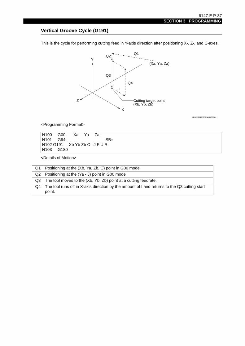
6147-E P-37SECTION 3 PROGRAMMING
Vertical Groove Cycle (G191)
This is the cycle for performing cutting feed in Y-axis direction after positioning X-, Z-, and C-axes.
<Programming Format>
<Details of Motion>
N100 G00 Xa Ya ZaN101 G94 SB=N102 G191 Xb Yb Zb C I J F U RN103 G180
Q1 Positioning at the (Xb, Ya, Zb, C) point in G00 mode
Q2 Positioning at the (Ya - J) point in G00 mode
Q3 The tool moves to the (Xb, Yb, Zb) point at a cutting feedrate.
Q4 The tool runs off in X-axis direction by the amount of I and returns to the Q3 cutting start point.
Q4
Q3
I
Q2
(Xa, Ya, Za)
Cutting target point(Xb, Yb, Zb)
Q1
X
Z
Y
LE61588R0200500160001

5946-E P-40SECTION 3 MATH FUNCTIONS
3-5. Torque Limit and Torque Skip Function
To transfer a workpiece from the first-process chuck to the second-process chuck with multi-process models*, the end face of the second-process chuck jaws must be pushed against the workpiece for stable workpiece seating. The torque limit command and the torque skip command are used to control the torque of the second-process chuck feed servomotor and to push the workpiece with the optimal thrust.
3-5-1. Torque Limit Command (G29)
[Function]Prior to workpiece transfer, designate the torque limit command to control the maximum torque of the second-process chuck feed servomotor.[Command format]G29 P Δ __
[Details]
The torque limit value is set as a percentage (%), proportionally to the rated torque of the axis feed servomotor.
The maximum torque limit value is set for optional parameter (OTHER FUNCTION 2).
3-5-2. Torque Limit Cancel Command (G28)
[Function]The torque limit cancel command cancels the maximum torque limit designated with G29.When this command is designated, the axis feed motor can output its maximum output torque.[Command format]G28
3-5-3. Torque Skip Command (G22)
[Command format]G22 Z__ D__ L__ F__ PZ =__
[Details]
For the target point and the set torque value, designate the axis to be fed.
An alarm (alarm A 1220) occurs if the preset torque value is not reached when the second-process chuck has moved to the virtual approaching point.
* : * Multi-process models include sub spindle models, opposing two-spindle models, etc.
Δ : Designate the feed axis name. Example: Z or W
Z : Target point (mm)
D : Distance between the target point and the approaching point as an incremental value (mm)
L : Distance between the target point and the virtual approaching point as an incremental value (mm)
F : Feed rate (mm/min or mm/rev)
PZ : Preset torque value (%)

5946-E P-41SECTION 3 MATH FUNCTIONS
Designate a value equal to or smaller than "2.5 m/min (8.20 fpm)" for F.
Before setting a value for PZ, check the actual motor torque value** at axis feed at the feed rate designated by F, and set a value for PZ which is larger than the actual torque value by 10%.
Feed rate F → F/5
* : Check the RLOAD value displayed on the axis data page of the CHECK DATA screen. If the preset torque value is too small, it is reached during approaching motion, resulting in an occurrence of alarm 1219.
Z : Target point
D : Distance between the target point and the approaching point as an incremental value
L : Distance between the target point and the virtual approaching point as an incremental value
First-process chuck Second-process chuck
The explanation here is for a case in which aworkpiece is transferred from the first-processchuck to the second-process chuck.
1. The second-process chuck approaches the workpiece at feedrate F.
2. The feedrate is reduced to 1/5 of F at the approaching point (Z - D) point).
3. The second-process chuck contacts the workpiece at target point Z. The servomotor is controlled so that the second-process chuck is kept pushed against the workpiece.
4. When the motor torque reaches the preset value, the NC recognizes workpiece seating to be complete, and the next program block is executed.
L D
Z
LE33019R0600500110001

5946-E P-42SECTION 3 MATH FUNCTIONS
3-5-4. Parameter Settings
Torque skip torque monitoring delay time
If motor torque monitoring is started at the start of torque skip feed designated by G22, the preset torque value could, in some cases, be exceeded on starting up the motor.To avoid this, set the torque monitoring delay time t for a parameter. Motor torque is not monitored for the time duration set for t.
Optional parameter (OTHER FUNCTION 2)
Torque skip torque upper limit
The upper limit for the P command value in the G29 block can be set.
Optional parameter (OTHER FUNCTION 2)
Setting unit
: 10 (ms)
Setting range
: 0 to 9999
Default : 0
Setting unit
: 1 (%)
Setting range
: 1 to 100
Default : 0
Motor torque
Set torque value
Torque monitor OFF
t
Torque monitor ON
Time
LE33019R0600500120001

5946-E P-43SECTION 3 MATH FUNCTIONS
3-5-5. Program example
This is a program example for transferring a workpiece to the sub spindle chuck.
60 50 45
W W
t
1000 mm/mim
200 mm/mim
Feedrate
::
::
G29 PW=30⋅⋅⋅⋅⋅⋅Limits the maximum torque of the sub spindle feed motor (W-axis motor). (30 %)G94 G22 W50 D5 L10 F1000 PW=25⋅⋅⋅⋅⋅⋅Pushes the sub spindle chuck against the workpiece end face by torque skipG29 PW=5⋅⋅⋅⋅⋅⋅Lowers the W-axis motor torque.M248⋅⋅⋅⋅⋅⋅Sub spindle chuck closeM84⋅⋅⋅⋅⋅⋅Main spindle chuck openG28⋅⋅⋅⋅⋅⋅Cancels W-axis torque limit.G90 G00 W300⋅⋅⋅⋅⋅⋅Returns the W-axis to the retract position at the rapid feedrate.
LE33019R0600500130001

5946-E P-281SECTION 9 CONTOUR GENERATION
SECTION 9 CONTOUR GENERATION
9-1. Contour Generation Programming Function (Face)
9-1-1. Overview
The contour generation function can cut straight lines or arcs on the end face of a workpiece by simultaneous two-axis interpolation of the C- and X-axes on multi-machining models.Note that simultaneous three-axis control of X, Z, and C axes is possible for straight line cutting on a plane.
9-1-2. Program Format
Straight line cutting
: G101 X Z C F
X, Z, C : Coordinates of target point on straight line
F : Cutting feed rate (mm/min)
Arc cutting : G102 X C L F
X, C : Coordinates of end point of clockwise arc
L : Arc radius
F : Cutting feed rate (mm/min)
: G103 X C L F
X, C : Coordinates of end point of counterclockwise arc
L : Arc radius
F : Cutting feed rate (mm/min)

5946-E P-282SECTION 9 CONTOUR GENERATION
9-1-3. Program example
Tool command
The specification method of tool command varies depending on the machine specification.Execute a tool command using any of T command, TL command, and TD command.The TL command and TD command are used with a multitasking machine.
The programs below are described using a T command.To use the TL command and TD command, create the program according to each command format.
Straight line cutting (G101)
Example 1:
Program 1: Simultaneous 2-axis control of X and C axes
C90
C270
C180 C0CA
CB
XB2
XA2
A′
XB = 100, ZB = 160CB = 60
(
XA = 100, ZA = 120CA = 300
(
X
Z
End point B
Start point A
Direction of C-axis rotation
Front View Section View of Point A′
LE33019R0601100030001
N101
N102
N103
N104
N105
M15
X100 C300
Z120
C60
T0101
M13
F30
SB = 250
M110
M146
G00
G94
G101
C-axis join
C-axis unclamp
Positioning
Start point A
End point B
……
……
……
……
……LE33019R0601100030002

5946-E P-283SECTION 9 CONTOUR GENERATION
Program 2: Simultaneous 3-axis control of X, Z and C axes
N101
N102
N103
N104
N105
M15
X100
Z160
C300
Z120
C60
T0101
M13
F30
SB = 250
M110
M146
G00
G94
G101
C-axis join
C-axis unclamp
Positioning
Start point A
End point B
……
……
……
……
……
LE33019R0601100030003

5946-E P-284SECTION 9 CONTOUR GENERATION
Example 2:
Program:
B
D
AC
XB2
XA2
XC2
XD2
XB = 100CB = 90
(
XA = 100CA = 0
(
XD = 100CD = 270
(
XC = 100CC = 180
(
Direction of C-axis rotation
LE33019R0601100030004
N101
N102
N103
N104
N105
N106
N107
N108
:
:
M15
X100
:
:
C0
Z120
C90
C180
C270
C0
T0101
M13
F30
SB = 250
M110
M146
G00
G94
G101
C-axis join
C-axis unclamp
Positioning
Start point A
End point B
End point C
End point D
End point A
……
……
……
……
……
……
……
……
LE33019R0601100030005

5946-E P-285SECTION 9 CONTOUR GENERATION
Arc cutting (G102, G103)
Example 1: G102
Program:
XB
CACB
2
C180 C0
XA2
XB = 100CB = 30
(
XA = 100CA = 330
(
C90
G102
L50
C270
Direction of C-axis rotation
End point B
Start point A
LE33019R0601100030006
N101
N102
N103
N104
N105
:
:
M15
X100
:
:
C330
Z120
C30
T0101
M13
L50
SB = 250
F30
M110
M146
G00
G94
G102
C-axis join
C-axis unclamp
Positioning
Start point A
End point B
………
………
………
………
………
LE33019R0601100030007

5946-E P-286SECTION 9 CONTOUR GENERATION
Example 2: G103
Program:
XA = 100CA = 30
(
XB = 100CB = 330
(
XC = 100CC = 270
(
XD = 100CD = 210
(
XE = 100CE = 150
(
XF = 100CF = 90
XA2
(
C90
G102
G103
L50
C0C180
A
B
C
C
D
E
C270
F
Direction of C-axis rotation
LE33019R0601100030008
N101
N102
N103
N104
N105
N106
N107
N108
N109
N110
:
:
M16
X100
:
:
C30
Z120
C330
C270
C210
C150
C90
C30
T0101
L50
L50
L50
L50
L50
L50
SB = 250
M13
F30
M110
M146
G00
G94
G103
C-axis join
C-axis unclamp
Positioning
Start point A
End point B
End point C
End point D
End point E
End point F
End point A
……
……
……
……
……
……
……
……
……
……
LE33019R0601100030009

5946-E P-287SECTION 9 CONTOUR GENERATION
Example 3: G103
Program:
C90
C270
C180 C0
C
B
A
L50
XB = 80CB = 180
( XA = 120CA = 0
(
XC = 120CC = 0
(
LE33019R0601100030010
N101
N102
N103
N104
N105
N106
:
:
M15
X120
Z120
X80
X120
:
:
C0
M13
C80
C0
T0101
L50
L50
SB = 250
F30
M110
M146
G00
G94
G103
C-axis join
C-axis unclamp
Positioning
Start point A
End point B
End point C
……
……
……
……
……
……
LE33019R0601100030011

5946-E P-288SECTION 9 CONTOUR GENERATION
Combination with Coordinate System Conversion Function
Example 1:
V1 = R (cutter radius)The cutter radius value should be set for common variable V1 in advance.Program:
C90+Y
+X
100
100
-Y
-X
C270
C180 C0
Point BStart point A
R (Cutter radius)
Point CPoint D
Direction of C-axis rotation
LE33019R0601100030012
N101
N102
N103
N104
N105
N106
N107
N108
N109
N110
:
:
M15
C0
X100+V1
X-100-V1
X-100-V1
X100+V1
X100+V1
:
:
Y100+V1
Z100
Y100+V1
Y-100-V1
Y-100-V1
Y100+V1
T0101
F30M13
SB = 250
M110
M146
G137
G00
G94
G101
G136
C-axis join
C-axis unclamp
Start of coordinate system conversion
Positioning at start point A
Cutting up to point B
Cutting up to point C
Cutting up to point D
Cutting up to point A
End of coordinate system conversion
……
……
……
……
……
……
……
……
……
LE33019R0601100030013

5946-E P-289SECTION 9 CONTOUR GENERATION
Example 2:
Where:
By setting r = 220 mm, ς = 60 mm, θ = 30°, R = 20 mm, and D = 250 mm,A will be 35°, a value greater than 29.6° based on formula (*).V1 = R (cutter radius)The cutter radius R should be set for common variable V1 in advance.
+Y
A C90
C180 C0
rR
Al D /2
+X
-X
-Y
C270
Start point A
End point B
r = radius of arc to be cutç = depth of cutθ = angleR = cutter radiusD = workpiece diameter
Data to be
designated:
The X and Y coordinate values of the start point can be calculated as follows:X = (r - R) sinAY = r + ç - (r - R) cosA
LE33019R0601100030014
A = cos-1 …………………(ς + r)2 + (r - R)2 - (D/2 + R)2
2(ς + r)(r - R)(*)
LE33019R0601100030015

5946-E P-290SECTION 9 CONTOUR GENERATION
Program:
[Supplement]
If the control does not support user task 2 (optional), it cannot perform trigonometric function calculations. Therefore, programming must be done by directly entering numeric values.
N101
N102
N103
N104
N105
N106
N107
:
:
M15
C30
X[200-V1]∗SIN[35]
SB=250
Z100 M13
X-[200-V1]∗SIN[35]
F30
:
:
Y220+60-[200-V1]∗COS[35]
Y220+60-[200-V1]∗COS[35]
M110
M146
G137
G00
T0101
G94
G102
L220-20
G136
C-axis join
C-axis unclamp
Start of coordinate system conversion
Positioning at start point A
Cutting up to point B
End of coordinate system conversion
……
……
……
……
……
……
LE33019R0601100030016

5946-E P-291SECTION 9 CONTOUR GENERATION
9-1-4. Supplementary Notes
Special operation in the G101 mode
If the tool paths commanded without the cutter radius compensation function or the tool paths calculated as a result of activation of the cutter radius compensation function are straight lines passing through the center of the X-C coordinate, the following special operation occurs.
(1) When the C commands of the start and end points are the same:
Although the G101 command calls for compound X- and C-axis motion, only the X-axis moves in this case (the same as G01 motion).
(2) When the start point lies at the center and the C commands of the start and end points differ:
In this case, only the C-axis moves until the commanded value is reached; then X-axis motion occurs.
(3) When the end point lies at the center and the C commands of the start and end points differ:
This case is the opposite of (2) above; only the X-axis moves until the commanded value is reached; then C-axis motion occurs.
C = 90°
C = 0°
End point
Start point
LE33019R0601100040001
C = 90°
C = 0°
End point
Start point
LE33019R0601100040002
C = 90°
C = 0°End point
Start point
LE33019R0601100040003

5946-E P-292SECTION 9 CONTOUR GENERATION
(4) When the start and end points lie at the opposite sides of the C-axis center with the C-axis commands at these points 180 degrees apart:
In this case, first only the X-axis moves until it reaches "0".Then, the C-axis moves by 180 degrees; after the completion of the 180-degree motion, the X-axis moves again.
In motions in (2), (3), and (4) above, C-axis motion is also controlled by the commanded feed rate. It is possible to activate the C-axis feed rate override by the setting at C-axis center override (%) of optional parameter (MULTIPLE MACHINING).
Special operation during G101 mode: Override value for C-axis feed is set.
Automatic feed rate control functionIf the commanded paths pass close the center of the X-C coordinate, the C-axis feed rate calculated from the designated compound feed rate (compound feed rate of X and C axes) might be excessively large.
For the commanded feed rate F, the C-axis feed rates change in the sequence Ca, Cb, Cc and Cf.In this case, the C-axis feed rate is the maximum at Cd.
Setting range : 1 ~ 1000 (%)
Default : 100 (%)
C = 90°
C = 0°
End point
Start point
LE33019R0601100040004
Ce
Cd
Cc
CbCa
Cf
F
Programmed tool path
LE33019R0601100040005

5946-E P-293SECTION 9 CONTOUR GENERATION
An excessively large C-axis feed rate to provide the commanded feed rate will cause the CON velocity alarm.The feed rate is limited automatically so that the C-axis feed rate will not exceed the CON velocity limit.In this case, however, the programmed feed rate changes during the execution of the commands.If not wishing to automatically control the feed rate, automatic control can be turned OFF at the parameter settings.Optional parameter: Contour generation face C-axis feed rate automatic control disable
In the G101, G102, and G103 mode, the direction of C-axis rotation is determined by the control according to the programmed shape, regardless of M15 or M16.
An alarm occurs if a C-axis command is designated in the M109 or M147 mode.
In the G102 or G103 mode, two arcs, satisfying the start and end points and arc radius L, are obtained. The control selects the arc with a center angle of less than 180 degrees. This means an arc having a center angle of larger than 180 degrees cannot be machined with a single block of commands. In this kind of case, divide the arc to make a program.If the G102 or G103 block does not contain an L command, the L value is not positive, or L is too small to define an arc, an alarm occurs.
Z-axis control cannot be performed for G102 and G103 designations. (An alarm will occur if the Z-axis is designated.)
To carry out the contour generation machining with the cutter radius compensation function ON, program the final shape.To carry out the contour generation machining with the cutter radius compensation function OFF, program the cutter center paths.
To give the face contour generation machining commands, the X-axis must be at a position greater than "0" in the program coordinate system. An alarm occurs if the face contour generation machining commands are specified although the X-axis is at a position not greater than "0" and an alarm occurs.

5946-E P-294SECTION 9 CONTOUR GENERATION
9-2. Contour Generation Programming Function (Side)
9-2-1. Overview
This function carries out arc-form machining on the periphery (side face) of a workpiece on a multiple machining model by feeding the Z-axis while rotating the C-axis.Programming is performed on the plane which is obtained by developing the cylindrical surface. Two different planes can be assumed: one is the "outer plane" as shown in Figs. 1 and 2, and the other is the "inner plane" as shown in Figs. 3 and 4. The plane used for programming, that is, the outer plane or inner plane, can be selected with the parameter indicated below:
Z-CE coordinate screen of optional parameter (MULTIPLE MACHINING)
Outer plane selection (Figs. 1 and 2)
Inner plane selection (Figs. 3 and 4)
<Outer Plane>
<Inner Plane>
The circular interpolation direction, tool nose radius compensation direction, and other factors are determined based on the selected plane.
C0
C360
Z
0
360
G132
G133
CFig. 1 Fig. 2
LE33019R0601100050001
C360
C0
Z
Fig. 3 Fig. 4
360
0 Z
G132
G133
C
LE33019R0601100050002

5946-E P-295SECTION 9 CONTOUR GENERATION
9-2-2. Program Format
9-2-3. Precautions
An alarm occurs if the X coordinate value of the start and end points are different.This is because the coordinate plane will be changed if the X coordinate values are different.
For circular interpolation between two points A and B on the side face, there are two possible paths which have the same radius.In this case, the arc whose center angle is less than 180 degrees is selected.In Fig. 5 below, the arc "a" is generated.
If performing circular interpolation for two points on the side face, even if the radius is the same and the center angle is within 180°, the C-axis coordinate is the rotational axis, and therefore the coordinates continue in 360° units.
Circular interpolation (CW) on side face
: G132 Z C L F
Z, C : Coordinates of end point for circular interpolation (CW) on contour generation side face
L : Radius of arc on side face
F : Cutting feed rate (mm/min)
Circular interpolation (CCW) on side face
: G133 Z C L F
Z, C : Coordinates of end point for circular interpolation (CCW) on contour generation side face
L : Radius of arc on side face
F : Cutting feed rate (mm/min)
* : The values in parentheses are for the inner plane.
(C360) C0
(C0) C360
Ba L
AL
b
Fig.5
LE33019R0601100070001

5946-E P-296SECTION 9 CONTOUR GENERATION
Consequently, two types of path are selected based on how the target points are obtained.
In such a case, an arc is generated according to M15/M16 (C-axis forward/reverse rotation command) designated preceding the arc command.Arc "a" (b) is generated when M15 is designated.Arc "b" (a) is generated when M16 is designated.
[Supplement]
Side Contour Generation Programming Mode Function
Making the mode valid/invalidThe side contour generation programming mode function is valid when "1" is set at optional parameter (bit) No. 39 bit 0.1: Side contour generation mode function - Enabled2: Side contour generation mode function - Disabled (default)
Designating the Side Contour Generation Programming ModeThe system enters the side contour generation programming mode when G119 is designated and the mode is turned off when G119 is canceled.Although G119 is originally used for the designation of the Z-C plane as the offset plane in the nose R compensation mode, it is also used to call out the side contour generation programming mode when this function is used.G119 is canceled in the following cases:
Designation of G138 (Y-axis mode ON)
Designation of G136 (Y-axis mode OFF)Note that G136 is used as the cancel code for G137 (coordinate conversion ON)
* : The values in parentheses are for the inner plane (in both the figures and the text).
When the C-axis is joined, machining is possible within a C-axis rotation range of 5965 turns (596 turns for the 0.1 μm specification) in one direction. If side contour generation machining that exceeds this limit is carried out, the following alarm message is displayed.Alarm B 2480 Profile generation calculation.If this alarm message is displayed, use the side contour generation programming mode function. The setting method is described below.
(C359.999) C0
(C0) C359.999
(C0) C359.999
(C359.999) C0
Fig.6
point A C80 (C280)point B C260 (C100)
Bb
AL
L
a
B
LE33019R0601100070002

5946-E P-297SECTION 9 CONTOUR GENERATION
Designation of M109 (C-axis control OFF)
Reset
RestrictionsWhen the side contour generation programming mode function is set as valid, the following restrictions apply. The side contour generation programming commands G132 and G133 may be designated only in the side contour programming mode. If G132 or G133 is designated other than in the side contour programming mode, the following alarm message is displayed.Alarm B 2224 UNUSABLE contour generation command

5946-E P-299SECTION 10 COORDINATE SYSTEM CONVERSION
SECTION 10 COORDINATE SYSTEM CONVERSION
10-1. Overview
Multiple-machining models have a function to convert the program commands designated in the Cartesian coordinate system into X and C-axis data in the polar coordinate system on-line. This function simplifies programming when a hole on the end face of a workpiece is not specified by the angle but by the vertical distance from a radius vector.
[Command format]
Start of coordinate system conversionG137 C__ __ __C Angle of C-axis that defines the orthogonal coordinate system (θ)
Cancellation of coordinate system conversionG136
[Details]
The rectangular coordinate system using the straight line in the angle C direction designated in the G137 block (zero: Z-axis) as the + X-coordinate axis is set. Thereafter, the designation is made with X and Y instead of X and C. In this case, both X and Y and radius commands.After the designation, commands are given using the X and Y words instead of using the X and C words. Values for the X and Y words are given as radius values. Prefix X and Y words of the specified Cartesian coordinate system with a plus (+) or minus (-) sign. (First quadrant X > 0 Y > 0 Second quadrant X < 0 Y > 0 Third quadrant X < 0 Y < 0 Fourth quadrant X > 0 Y < 0.)
Following the G137 command, either a fixed cycle or G01 can be used as the machining command after positioning with the X and Y commands. However, G00, G01, and the fixed cycle G code are canceled with the coordinate conversion command, and therefore they must be designated again at the next block.
If the coordinate conversion command is designated while the X- or Z- axis is at its travel end limit position, an alarm occurs.
+Y
+X
Z C = 0°θ
LE33019R0601200010001

5946-E P-300SECTION 10 COORDINATE SYSTEM CONVERSION
10-2. Conversion Format
The radius vector and C-axis angle after coordinate conversion are calculated with the formula below.
θ C = 0°
+Y
+X
X
Y
CX′
Radius vector, X′ = X2 + Y2
Angle, C = tan-1(Y/X) + θ
LE33019R0601200020001

5946-E P-301SECTION 10 COORDINATE SYSTEM CONVERSION
10-3. Program example
G137 is effective until G136 is designated. Do not designate other commands in the G136 block.For the C command in a G137 block, designate the angle in reference to the C-axis zero point.This angle is equivalent to "θ" in the figure in 2. "Conversion Format" above.After designation of G137, use X and Y words instead of X and C words as positioning commands until G136 is designated.Example 1: Fixed cycle machining at P1
Example 2: G01 mode machining at P2
Note: Use X and Y words only for positioning.
N01
N02
N03
N04
G137
G181
G180
G136
C20
X10 Y50 Z125 Q2 F30 K10
LE33019R0601200030001
+Y
+X
10
C = 0°
10
50
50
20°
P1
P2
N011
N012
N013
N014
N015
N016
G137
G00
G94
G01
G00
G136
C20
X-10
Z125
Z150
Y-50
F30
LE33019R0601200030002

5946-E P-302SECTION 10 COORDINATE SYSTEM CONVERSION
10-4. Supplementary Notes
When creating the orthogonal coordinate system by the coordinate system conversion command, it is possible to select whether or not the C-axis zero shift is included by the setting at the following parameter:C-axis zero shift in G137 of optional parameter (MULTIPLE MACHINING)
[Supplement]
1) Designate both X and Y words in the first block after the G137 block.When only an X or Y word is designated, an alarm occurs. This does not apply to the subsequent blocks.
2) When an incremental command is designated in the G137 mode, an alarm occurs.To designate incremental commands in the G137 mode, proceed as follows. Cancel the incremental programming mode in the block before the G137 block. Designate X and Y words in the absolute programming mode in the first block following the G137 block. Designate the incremental programming mode.<Example Program>
When the G90 before the G137 block is omitted, an alarm occurs.
3) An alarm will occur if an incremental command (G91) is designated without even oncedesignating an absolute command after the coordinate conversion command (G137).If G91 is designated in the block right after the G137 block, an alarm occurs.
:
:
:
:
:
:
:
:
G91
G90
G137
G00
G91
G00
G90
G136
Incremental programming mode ON machining
Machining
Cancel the incremental programming mode before designating G137
Coordinate system conversion
Designate an absolute value for X and Y
Incremental programming mode ON
Machining
Cancel the incremental programming mode
Cancel coordinate system conversion
C180
X50
X-50
Y50
.............
.............
.............
.............
.............
.............
.............
LE33019R0601200040001

AXIAL LIVE DRILLING
5.00
2.00
4.00
3.00
.5 dia x 1 dp
.75
.63
3 2
ALD1SHEET 1 OF 1SCALE: NONE
REVDWG. NO.
ASIZE
TITLE:
5 4 1

1.50
4.72
2.00
.75
3 2
ALD2SHEET 1 OF 1SCALE: NONE
REVDWG. NO.
ASIZE
TITLE:
5 4 1
.76
1.74
.40 2PLCS
RADIAL LIVE DRILLING

AXIAL LIVE DRILLINGMULTIPLE POSITIONS
1/4-20, .5DP4 BHC, AS SHOWN
3 2
ALD3SHEET 1 OF 1SCALE: NONE
REVDWG. NO.
ASIZE
TITLE:
5 4 1
3.00
5.00
5.00
6.00

R1.50
3 2
ALD4SHEET 1 OF 1SCALE: NONE
REVDWG. NO.
ASIZE
TITLE:
5 4 1
RADIAL LIVE MILLINGOPTIONAL Y AXIS FOR SIZE
3.00
.50 X .5DP
2.00
5.00
6.00

.70 .70
3 2
ALD5SHEET 1 OF 1SCALE: NONE
REVDWG. NO.
ASIZE
TITLE:
5 4 1
1.00 4.00
4.75
2 PLCS.38 X .88DP, 3.50
R2.00
1.60
3.00
7.00
5.00
2.00
6.00
Y AXIS MILLING, DRILLINGAND TAPPING

3 2
ALD6SHEET 1 OF 1SCALE: NONE
REVDWG. NO.
ASIZE
TITLE:
5 4 1
1.00
2.00
2.00
2.00
4.00
3.00
1/4-20 X 1.0 DP.05 X 45 CHAMFER
3.00 TYP
A
A
RADIAL DRILING AND TAPPINGSUB SPINDLE PICK OFF,& ORIENTATION
SECTION A-A5/16-18 X 1DP
.05 X 45 CHAMFER

3 2
ALD7SHEET 1 OF 1SCALE: NONE
REVDWG. NO.
ASIZE
TITLE:
5 4 1
2.50 .50 .50
R.05 TYP.
AXIAL AND RADIAL MILLING,CONTOUR GENERATION AND Y AXIS, SUB SPINDLE PICK-OFF
1.25 HEX
1.00
1.50

1.22
4PLCS.50 x .75DP
.99 .59
.74 .93
.83
.93 .65
4.00
SECTION A-A
1.0
1.011.00
A
A
4.25
COORDINATE CONVERSION & MILLING WITH X AXIS
3 2
ALD8SHEET 1 OF 1SCALE: NONE
REVDWG. NO.
ASIZE
TITLE:
5 4 1

2
ALD9SHEET 1 OF 1SCALE: NONE
REVDWG. NO.
ASIZE
TITLE:
5 4 3 1
2.50
5.00
2.00
2.80
R.50 TYP.
CONTOUR GENERATION
2.00
8.00
2.70

2
ALD10SHEET 1 OF 1SCALE: NONE
REVDWG. NO.
ASIZE
TITLE:
5 4 3 1
4.50
4.00
5.00
2.00
1.00
4.00
.50 THRU,2 PLCS
LIVE DRILLING, MILLING, SUB SPINDLE PICK-OFF, CONTOURGENERATION, Y AXIS.
.25WIDE X .3 DPKEYWAY
.63
2.75
2.50
.50
3.00
2.00

5238-E P-352SECTION 15 APPENDIX
SECTION 15 APPENDIX
1. G Code Table
Code Function Standard/OptionalG00 Positioning StandardG01 Linear interpolation StandardG02 Circular interpolation (CW) StandardG03 Circular interpolation (CCW) StandardG04 Dwell StandardG05G06G07G08G09G10 Canceled of G11 OptionalG11 Parallel and rotational shift of coordinate system OptionalG12G13 Turret selection: Turret A OptionalG14 Turret selection: Turret B OptionalG15 Selection of work coordinate system (Modal) OptionalG16 Selection of work coordinate system (One-shot) OptionalG17 Cutter radius compensation: X-Y plane OptionalG18 Cutter radius compensation: Z-X plane OptionalG19 Cutter radius compensation: Y-Z plane OptionalG20 Home position return command OptionalG21 ATC home position return command OptionalG22 Torque skip command OptionalG23
G24 ATC home position movement command (without linear interpolation) Optional
G25 Joint position movement command (without linear interpolation) OptionalG26G27G28 Torque limit command cancel OptionalG29 Torque limit command OptionalG30 Skip cycle OptionalG31 Fixed thread cutting cycle: Longitudinal StandardG32 Fixed thread cutting cycle: End face StandardG33 Fixed thread cutting cycle StandardG34 Variable lead thread cutting cycle: Increasing lead StandardG35 Variable lead thread cutting cycle: Decreasing lead StandardG36 M-tool spindle - feed axis synchronized feeding (forward) OptionalG37 M-tool spindle - feed axis synchronized feeding (reverse) Optional
5238-E P-353SECTION 15 APPENDIX
G38G39G40 Cutter radius compensation: Cancel StandardG41 Cutter radius compensation: Left StandardG42 Cutter radius compensation: Right StandardG43G44G45G46G47G48G49G50 Zero shift, Maximum spindle speed designation StandardG51G52 Turret index position error compensation OptionalG53G54G55G56G57G58G59G60G61G62 Mirror image designation OptionalG63G64 Droop control OFF StandardG65 Droop control ON StandardG66G67G68G69G70G71 Compound fixed thread cutting cycle: Longitudinal StandardG72 Compound fixed thread cutting cycle: Transverse StandardG73 Longitudinal grooving compound fixed cycle StandardG74 Transverse grooving compound fixed cycle StandardG75 Automatic chamfering StandardG76 Automatic rounding StandardG77 Tapping compound fixed cycle StandardG78 Tapping cycle reverse thread StandardG79G80 End of shape designation (LAP) OptionalG81 Start of longitudinal shape designation (LAP) Optional
Code Function Standard/Optional
5238-E P-354SECTION 15 APPENDIX
G82 Start of transverse shape designation (LAP) OptionalG83 Start of blank material shape definition (LAP) OptionalG84 Change of cutting conditions in bar turning cycle (LAP) OptionalG85 Call of rough bar turning cycle (LAP) OptionalG86 Call of rough copy turning cycle (LAP) OptionalG87 Call of finish turning cycle (LAP) OptionalG88 Call of continuous thread cutting cycle (LAP) OptionalG89G90 Absolute programming StandardG91 Incremental programmingStandard StandardG92G93G94 Feed per minute mode (mm/min) StandardG95 Feed per revolution mode (mm/rev) StandardG96 Constant speed cutting ON StandardG97 Cancel of G96 StandardG98G99
G100 Priority designating for turret A or B independent cutting OptionalG101 Linear interpolation in contour generation OptionalG102 Circular interpolation in contour generation (Face) (CW) OptionalG103 Circular interpolation in contour generation (Face) (CCW) OptionalG104G105G106G107 Spindle synchronization tapping, RH thread OptionalG108 Spindle synchronization tapping, LH thread OptionalG109G110 Constant speed cutting on turret A StandardG111 Constant speed cutting on turret B StandardG112 Circular thread cutting CW OptionalG113 Circular thread cutting CCW OptionalG114G115G116 Z-W axis superimpose mode cancel OptionalG117 Z-W axis superimpose mode effect OptionalG118G119 Nose-R compensation: C-X-Z plane OptionalG120G121G122 W-axis command for sub spindle on turret A (G13) OptionalG123 W-axis command for sub spindle on turret B (G14) OptionalG124 A-chuck coordinate system selection (ACC) OptionalG125 B-chuck coordinate system selection (ACC) Optional
Code Function Standard/Optional
5238-E P-355SECTION 15 APPENDIX
G126 Slant process mode cancel OptionalG127 Slant process mode effect OptionalG128 Machining mode cansel OptionalG129 Machining mode OptionalG130G131G132 Circular interpolation in contour generation (Side)(CW) OptionalG133 Circular interpolation in contour generation (Side)(CCW) OptionalG134G135G136 End of coordinate conversion or Y-axis mode OFF OptionalG137 Start of coordinate conversion OptionalG138 Y-axis mode ON OptionalG139G140 Designation of machining mode using main spindle OptionalG141 Designation of machining mode using sub spindle OptionalG142 Designation of machining mode using pick-off spindle OptionalG143G144 W-axis control OFF command OptionalG145 W-axis control ON command OptionalG146G147G148 B-axis mode OFF commandOptional OptionalG149 B-axis mode ON commandOptional OptionalG150 M/C cutting mode cancelOptional OptionalG151 M/C cutting mode effectOptional OptionalG152 Programmable tailstock positioning (tow-along tailstock) OptionalG153 Programmable steadyrest G code (tow-along) OptionalG154 W-axis unidirectional positioning command OptionalG155 Accurate contouring mode ON command OptionalG156 Accurate contouring mode OFF command OptionalG157 Grinding mode effect OptionalG158 Tool length offset in tool axis direction Optional
G159 Tool length offset in tool axis direction (without rotary position offset) Optional
G160 Tool length offset in tool axis direction cancelG161 G code macro function MODIN OptionalG162 G code macro function MODIN OptionalG163 G code macro function MODIN OptionalG164 G code macro function MODIN OptionalG165 G code macro function MODIN OptionalG166 G code macro function MODIN OptionalG167 G code macro function MODIN OptionalG168 G code macro function MODIN Optional
Code Function Standard/Optional

5238-E P-356SECTION 15 APPENDIX
G169 G code macro function MODIN OptionalG170 G code macro function MODIN OptionalG171 G code macro function CALL (fixed sub-program name) OptionalG172 G code macro function CALL (fixed sub-program name) OptionalG173 G code macro function CALL (fixed sub-program name) OptionalG174 G code macro function CALL (fixed sub-program name) OptionalG175 G code macro function CALL (fixed sub-program name) OptionalG176G177G178 M-tool compound fixed cycle: Synchronized tapping cycle (CW) Optional
G179 M-tool compound fixed cycle: Synchronized tapping cycle (CCW) Optional
G180 M-tool compound fixed cycle: Cancel OptionalG181 M-tool compound fixed cycle: Drilling OptionalG182 M-tool compound fixed cycle: Boring OptionalG183 M-tool compound fixed cycle: Deep hole drilling OptionalG184 M-tool compound fixed cycle: Tapping OptionalG185 M-tool compound fixed cycle: Longitudinal thread cutting OptionalG186 M-tool compound fixed cycle: End face thread cutting Optional
G187 M-tool compound fixed cycle: Longitudinal straight thread cutting Optional
G188 M-tool compound fixed cycle: Transverse straight thread cutting OptionalG189 M-tool compound fixed cycle: Reaming/boring OptionalG190 M-tool compound fixed cycle: Keyway cutting cycle OptionalG191 M-tool compound fixed cycle: Longitudinal keyway cutting cycle OptionalG192G193G194G195G196G197G198G199G200G201G202G203G204G205 G code macro function CALL OptionalG206 G code macro function CALL OptionalG207 G code macro function CALL OptionalG208 G code macro function CALL OptionalG209 G code macro function CALL OptionalG210 G code macro function CALL Optional
Code Function Standard/Optional
5238-E P-357SECTION 15 APPENDIX
G211 G code macro function CALL OptionalG212 G code macro function CALL OptionalG213 G code macro function CALL OptionalG214 G code macro function CALL OptionalG215G216G217G218G219G220G221G222G223G224G225G226G227G228G229G230G231G232G233G234G235G236G237G238G239G240G241G242G243G244G245G246G247G248G249G250G251G252G253G254
Code Function Standard/Optional
5238-E P-358SECTION 15 APPENDIX
G255G256G257G258G259G260G261G262G263G264 Super-NURBS control OFF OptionalG265 Super-NURBS control ON OptionalG266G267G268G269G270 Turnning mode OptionalG271 C-axis machining mode OptionalG272 Y-axis machining mode OptionalG273G274G275G276G277G278G279G280
Code Function Standard/Optional
5238-E P-359SECTION 15 APPENDIX
2. M Code Table
Code Function Standard/OptionalM00 Program stop StandardM01 Optional stop StandardM02 End of program Standard
M03 Spindle CW [Rotates the work spindle counterclockwise when viewed from the workpiece.] Standard
M04 Spindle CCW [Rotates the work spindle clockwise when viewed from the workpiece.] Standard
M05 Spindle stop StandardM06 Tool change OptionalM07M08 Coolant 1 ON StandardM09 Coolant 1 OFF StandardM10 Spindle inching OFF OptionalM11 Spindle inching ON OptionalM12 M-tool spindle stop OptionalM13 M-tool spindle CW OptionalM14 M-tool spindle CCW OptionalM15 C-axis positioning (positive direction) OptionalM16 C-axis positioning (negative direction) OptionalM17 Post-pro OptionalM18 Oriented spindle stop cancel OptionalM19 Oriented spindle stop 1 OptionalM20 Tailstock barrier OFF or spindle interference monitoring OFF StandardM21 Tailstock barrier ON or spindle interference monitoring ON StandardM22 Chamfering OFF StandardM23 Chamfering ON StandardM24 Chuck barrier OFF,tool interference OFF StandardM25 Chuck barrier ON,tool interference ON StandardM26 Thread lead along Z-axis StandardM27 Thread lead along X-axis StandardM28 Tool interference check function OFF StandardM29 Tool interference check function ON StandardM30 End of program StandardM31M32 Straight infeed along thread face mode (on left face) StandardM33 Zig-zag infeed in thread cutting StandardM34 Straight infeed along thread face mode (on right face) StandardM35 Loader gripper Z slide retract OptionalM36 Loader gripper Z slide advance OptionalM37 Loader arm retract OptionalM38 Loader arm advance to unloading position OptionalM39 Loader arm advance to chuck position Optional

5238-E P-360SECTION 15 APPENDIX
M40 Spindle gear range neutral StandardM41 Spindle gear range 1 or low-speed coil selection StandardM42 Spindle gear range 2 or high-speed coil selection StandardM43 Spindle gear range 3 StandardM44 Spindle gear range 4 StandardM45M46M47M48 Spindle speed override ignore cancel OptionalM49 Spindle speed override ignore OptionalM50 Air blower B OFF OptionalM51 Air blower B ONOptional OptionalM52M53M54 Automatic indexing of index chuck OptionalM55 Tailstock spindle retract OptionalM56 Tailstock spindle advance OptionalM57 Cancel of M63 OptionalM58 Chuking pressure low StandardM59 Chuking pressure high StandardM60 Cancel of M61 StandardM61 Ignoring fixed speed arrival in constant speed cutting StandardM62 Cancel of M64 OptionalM63 Ignoring spindle ratation M code answer OptionalM64 Ignoring general M code answer OptionalM65 Ignoring T code answer OptionalM66 Turret indexing position free OptionalM67 Synchronized mode cancel in cam turning cycle OptionalM68 Synchronized mode A ON OptionalM69 Synchronized mode B ON OptionalM70 Manual tool change command OptionalM71M72M73 Thread cutting pattern 1 OptionalM74 Thread cutting pattern 2 OptionalM75 Thread cutting pattern 3 OptionalM76 Parts catcher retract OptionalM77 Parts catcher advance OptionalM78 Steady rest unclamp OptionalM79 Steady rest clamp OptionalM80 Overcut advance OptionalM81 Overcut retract OptionalM82M83 Chuck clamp Standard
Code Function Standard/Optional
5238-E P-361SECTION 15 APPENDIX
M84 Chuck unclamp Standard
M85 No return to the cutting starting point after the rough turning cycle Optional
M86 Turret indexing direction reverse StandardM87 Cancel of M86 StandardM88 Air blower A OFF StandardM89 Air blower A ON StandardM90 Cover close OptionalM91 Cover open OptionalM92 Bar feeder retract OptionalM93 Bar feeder advance OptionalM94 Loader loading OptionalM95 Loader unloading OptionalM96 Parts catcher for sub spindle retract OptionalM97 Parts catcher for sub spindle advance OptionalM98 Tailstock spindle thrust low StandardM99 Tailstock spindle thrust high StandardM100 Waiting for synchronization command StandardM101 External M codeOptional OptionalM102 External M codeOptional OptionalM103 External M codeOptional OptionalM104 External M codeOptional OptionalM105 External M codeOptional OptionalM106 External M codeOptional OptionalM107 External M codeOptional OptionalM108 External M codeOptional OptionalM109 Cancel of M110 OptionalM110 C-axis joint OptionalM111M112M113M114M115 Unloader open OptionalM116 Unloader close OptionalM117 Sensor head advance OptionalM118 Sensor head retract OptionalM119 Work count special OptionalM120 No work confirmation OptionalM121 Steady rest close end OptionalM122 Steady rest retract OptionalM123 Steady rest advance OptionalM124 STM time over check ON OptionalM125 STM time over check OFF OptionalM126 Air blower D OFF Optional
Code Function Standard/Optional
5238-E P-362SECTION 15 APPENDIX
M127 Air blower D ON OptionalM128 Tailstock swing retract OptionalM129 Tailstock swing advance OptionalM130 Chucking error detecting air OFF OptionalM131 Chucking error detecting air ON OptionalM132 Chucking error detection OFF OptionalM133 Chucking error detection ON OptionalM134 Z-axis thrust monitoring OFF OptionalM135 Z-axis thrust monitoring ON OptionalM136 Shape designation for compound fixed cycle OptionalM137 Touch setter interlock release ON OptionalM138 Touch setter interlock release OFF OptionalM139 Lead machining function - learning operation OptionalM140 Tapping cycle M-tool constant rotation answer ignored OptionalM141 C-axis clamp or not selection OptionalM142 Coolant pressure low OptionalM143 Coolant pressure high OptionalM144 Coolant 1 OFF OptionalM145 Coolant 1 ON OptionalM146 C-axis unclamp OptionalM147 C-axis clamp OptionalM148M149M150 Synchronized rotation OFF OptionalM151 Synchronized rotation ON OptionalM152 M-tool spindle interlock ON OptionalM153 M-tool spindle interlock OFF OptionalM154 Air blower C OFF OptionalM155 Air blower C ONOptional OptionalM156 Center work interlock OFF StandardM157 Center work interlock ON StandardM158M159M160 Cancel of M161 StandardM161 Feedrate override fix (100%) StandardM162 Cancel of M163 OptionalM163 M-tool spindle speed override fix (100%) OptionalM164 Cancel of M165 StandardM165 Ignoring slide hold and single block StandardM166 Ignoring tailstock spindle advance/retract interlack OFF OptionalM167 Ignoring tailstock spindle advance/retract interlack ON OptionalM168 Loader mode OFF OptionalM169 Loader mode ON OptionalM170 C-Axis brake release mode ON Optional
Code Function Standard/Optional
5238-E P-363SECTION 15 APPENDIX
M171 C-Axis brake release mode OFF OptionalM172 Robot inside the lathe interlock release OFF OptionalM173 Robot inside the lathe interlock release ON OptionalM174 Coolant 2 OFF OptionalM175 Coolant 2 ON OptionalM176 Y-axis unclamp OptionalM177 Y-axis clamp OptionalM178M179M180 Robot/loader request 1 OptionalM181 Robot/loader request 2 OptionalM182 Robot/loader request 3 OptionalM183 Robot/loader request 4 OptionalM184 Chuck internal interlock release OFF OptionalM185 Chuck internal interlock release ON OptionalM186 Air blower F OFF OptionalM187 Air blower F ON OptionalM188 Tailstock joint OFF OptionalM189 Tailstock joint ON OptionalM190 Designation of G00 possible with tailstock joint OptionalM191 M-tool spindle orientation direction specified CW OptionalM192 M-tool spindle orientation direction specified CCW OptionalM193 Cancel of M194 OptionalM194 Phasing for thread cutting OptionalM195 Cancel of M196 OptionalM196 Thread cutting phasing stroke effective OptionalM197 Thread cutting phasing stroke clear OptionalM198M199M200 Z-axis synchronized feeding cancel OptionalM201 Z-axis synchronized feeding G13 OptionalM202 Z-axis synchronized feeding G14 OptionalM203 Turret unclamp OptionalM204 ATC shutter close OptionalM205 ATC shutter open OptionalM206 A/B saddle synchronaized feed mode OFF OptionalM207 A/B saddle synchronaized feed mode ON OptionalM208 Door interlock release OFF StandardM209 Door interlock release ON StandardM210 Cancel of phasing for synchronized rotation or flat turning OptionalM211 Keyway cutting cycle: Minus direction OptionalM212 Keyway cutting cycle: Zigzag OptionalM213 Keyway cutting cycle: Designated depth infeed OptionalM214 Keyway cutting cycle: Equal depth infeed Optional
Code Function Standard/Optional

5238-E P-364SECTION 15 APPENDIX
M215 Load monitor G00 ignore OFF OptionalM216 Load monitor G00 ignore ON OptionalM217 M-tool orientation for turret index OptionalM218 Air blower E OFF OptionalM219 Air blower E ON OptionalM220 Flat turning OFF OptionalM221 Flat turning ON (1:1) OptionalM222 Flat turning ON (1:2) OptionalM223 Flat turning ON (1:3) OptionalM224 Flat turning ON (1:4) OptionalM225 Flat turning ON (1:5) OptionalM226 Flat turning ON (1:6) OptionalM227 ATC operation completion waiting command OptionalM228 ATC next tool return command OptionalM229 M-tool spindle orientation OptionalM230 External M signal OptionalM231 External M signal OptionalM232 External M signal OptionalM233 External M signal OptionalM234 External M signal OptionalM235 External M signal OptionalM236 External M signal OptionalM237 External M signal OptionalM238 M-spindle phase variation OptionalM239 Sub spindle orientation OptionalM240 Steady rest 2 close end OptionalM241 M-tool spindle low-speed range OptionalM242 M-tool spindle high-speed range OptionalM243 Chip conveyer stop OptionalM244 Chip conveyer start OptionalM245 M246 Sub spindle chuck interlock release OFF OptionalM247 Sub spindle chuck interlock release ON OptionalM248 Sub spindle chuck clamp OptionalM249 Sub spindle chuck unclamp OptionalM250 Work pusher retract OptionalM251 Work pusher advance OptionalM252 Laser interferometer data write OptionalM253 Laser interferometer data verify OptionalM254 M255 M256 Robot/loader request 5 OptionalM257 Robot/loader request 6 OptionalM258 Robot/loader request 7 Optional
Code Function Standard/Optional
5238-E P-365SECTION 15 APPENDIX
M259 Robot/loader request 8 OptionalM260 Step feed mode OFF OptionalM261 Step feed mode ON OptionalM262 Tool holder Coolant OFF OptionalM263 Tool holder Coolant ON OptionalM264 Restriction on overlap mode rapid feed release OFF OptionalM265 Restriction on overlap mode rapid feed release ON OptionalM266M267M268M269 Optical sensor power off OptionalM270 Optical sensor start/stop , Optical sensor power on OptionalM271 Spindle extreme low speed rotation mode ON OptionalM272 Spindle extreme low speed rotation mode OFF OptionalM273 2nd software limit effective OptionalM274 2nd software limit ineffective OptionalM275M276 ATC 1st shutter close OptionalM277 ATC 1st shutter open OptionalM278 Steady rest 2 unclamp OptionalM279 Steady rest 2 clamp OptionalM280M281 M282 M283 M284 M285 M286 M287 M288 Sub spindle air blower OFF OptionalM289 Sub spindle air blower ON OptionalM290 Ceiling door close OptionalM291 Ceiling door open OptionalM292 M293 M294 M295 M296 Time constant switching (for less cut marks) OptionalM297 Time constant switching (for efficient shaping) OptionalM298 Cancel of M299 OptionalM299 Repeat function OFF in cam turning cycle OptionalM300 Hand A close (Y Hand close) OptionalM301 Hand A open (Y Hand open) OptionalM302 Hand index A position Optional
Code Function Standard/Optional
5238-E P-366SECTION 15 APPENDIX
M303 Hand index B position OptionalM304M305M306 Workpiece pusher A advance (Y Slide advance) OptionalM307 Workpiece pusher A retract (Y Slide retract) OptionalM308 Swing hand A (Y hand Swing A) OptionalM309 Swing hand B (Y hand Swing B) OptionalM310 Hand B close (V Hand close) OptionalM311 Hand B open (V Hand open) OptionalM312 Tandem loader turn over OptionalM313 Hand clamp miss check effective OptionalM314 Hand clamp miss check ineffective OptionalM315 Wrist turn angle 90 OptionalM316 Workpiece pusher A advance (V Slide advance) OptionalM317 Workpiece pusher A retract (V Slide retract) OptionalM318 Robot/loader air blower ON OptionalM319 Robot/loader air blower OFF OptionalM320 Robot/loader general M code 1 OptionalM321 Robot/loader general M code 2 OptionalM322 Robot/loader general M code 3 OptionalM323 Robot/loader general M code 4 OptionalM324 Robot/loader general M code 5 OptionalM325 Robot/loader general M code 6 OptionalM326 Robot/loader general M code 7 OptionalM327 Robot/loader general M code 8 OptionalM328 Request home position valid OptionalM329 Request home position invalid OptionalM330 NC start OptionalM331 Buffering prohibit OptionalM332 Clamp check effective OptionalM333 Clamp check ineffective OptionalM334 Interference with NC lathe OFF OptionalM335 Interference with NC lathe ON OptionalM336 External start OptionalM337 Work count OptionalM338 A-workpiece designation OptionalM339 B-workpiece designation OptionalM340 Robot/loader general M code 9 OptionalM341 Robot/loader general M code 10 OptionalM342 Robot/loader general M code 11 OptionalM343 Robot/loader general M code 12 OptionalM344 Robot/loader general M code 13 OptionalM345 Robot/loader general M code 14 OptionalM346 Robot/loader general M code 15 Optional
Code Function Standard/Optional
5238-E P-367SECTION 15 APPENDIX
M347 Robot/loader general M code 16 OptionalM348 External program selection (BCD) OptionalM349 Lot completion OptionalM350 NC lathe selection 1 (LFS-2SP: R machine) OptionalM351 NC lathe selection 2 (LFS-2SP: L machine) OptionalM352 NC lathe selection 3 OptionalM353 Work pusher retract OptionalM354 Work pusher advance OptionalM355 Tailstock spindle retract 2 OptionalM356 Tailstock spindle advance 2 OptionalM357 Work kind data change OptionalM358 NG shoot full work OptionalM359 Spindle orientation 2nd position OptionalM360 2nd chucking error detection air OFF OptionalM361 2nd chucking error detection air ON OptionalM362 R turn over device hand close OptionalM363 R turn over device hand open OptionalM364 R turn over device retract OptionalM365 R turn over device advance OptionalM366 NC lathe home positoin move command 1 OptionalM367 NC lathe home positoin move command 2 OptionalM368 NC lathe home positoin move command 3 OptionalM369 NC lathe home positoin move command 4 OptionalM370 Robot/loader general M code 17 OptionalM371 Robot/loader general M code 18 OptionalM372 Robot/loader general M code 19 OptionalM373 Robot/loader general M code 20 OptionalM374 Robot/loader general M code 21 OptionalM375 Robot/loader general M code 22 OptionalM376 Robot/loader general M code 23 OptionalM377 Robot/loader general M code 24 OptionalM378 Swing V-hand A OptionalM379 Swing V-hand B OptionalM380 NC lathe power saving OFF OptionalM381 NC lathe power saving ON OptionalM382 NC lathe home positoin move command 5 OptionalM383 NC lathe home positoin move command 6 OptionalM384 NC lathe home positoin move command 7 OptionalM385 NC lathe home positoin move command 8 OptionalM386 Work turn over return OptionalM387 Work turn over OptionalM388 2nd air blower A OFF OptionalM389 2nd air blower A ON OptionalM390 2nd door close Optional
Code Function Standard/Optional

5238-E P-368SECTION 15 APPENDIX
M391 2nd door open OptionalM392 Spindle oscillation OptionalM393 2nd spindle head down OptionalM394 2nd spindle head up Optional
M395 Feed interlock release when 2nd spindle not up or down position OFF Optional
M396 Feed interlock release when 2nd spindle not up or down position ON Optional
M397 T-No. for loader in permission pot OptionalM398 Measure unit on machine measurement start OptionalM399 2nd NC lathe home position move command 4 OptionalM400 Stopper lock off OptionalM401 Stopper lock on OptionalM402 Notice of program end OptionalM403 B-axis unclamp OptionalM404 B-axis clamp OptionalM405 Ignoring loader feed hold OptionalM406 Steady rest joint OFF (clamp) OptionalM407 Steady rest joint ON (unclamp) OptionalM408 Robot/loader interface interlock release OFF OptionalM409 Robot/loader interface interlock release ON OptionalM410 Tail stock quill thrust 1 OptionalM411 Tail stock quill thrust 2 OptionalM412 Robot/loader request 9 OptionalM413 Robot/loader request 10 OptionalM414 Robot/loader request 11 OptionalM415 Robot/loader request 12 OptionalM416 Robot/loader request 13 OptionalM417 Robot/loader request 14 OptionalM418 Robot/loader request 15 OptionalM419 2nd spindle orientaion OptionalM420M421 M code macro function CALL (fixed sub-program) OptionalM422 M code macro function CALL (fixed sub-program) OptionalM423 M code macro function CALL (fixed sub-program) OptionalM424 M code macro function CALL (fixed sub-program) OptionalM425 M code macro function CALL (fixed sub-program) OptionalM426 Ring sensor selection cancel OptionalM427 Ring sensor selection ON OptionalM428 Tailstock position data request OptionalM429 Chuck pressure select OptionalM430M431M432 Tail stock error detect OFF Optional
Code Function Standard/Optional
5238-E P-369SECTION 15 APPENDIX
M433 Tail stock error detect ON OptionalM434M435M436 Bar feeder assist command 1 OptionalM437M438M439 Coolant 4 OFF OptionalM440 Coolant 4 ON OptionalM441 M code macro function CALL OptionalM442 M code macro function CALL OptionalM443 M code macro function CALL OptionalM444 M code macro function CALL OptionalM445 M code macro function CALL OptionalM446 M code macro function CALL OptionalM447 M code macro function CALL OptionalM448 M code macro function CALL OptionalM449 M code macro function CALL OptionalM450 M code macro function CALL OptionalM451 M code macro function CALL OptionalM452 M code macro function CALL OptionalM453 M code macro function CALL OptionalM454 M code macro function CALL OptionalM455 M code macro function CALL OptionalM456 M code macro function CALL OptionalM457 M code macro function CALL OptionalM458 M code macro function CALL OptionalM459 M code macro function CALL OptionalM460 M code macro function CALL OptionalM461 Work stopper retract OptionalM462 Work stopper advance OptionalM463 Turn over device unclamp OptionalM464 Turn over device clamp OptionalM465M466M467M468 Cut finish notice, Spindle in center SOL 1 OFF OptionalM469 Spindle in center SOL 1 ON OptionalM470 Work ejector unit down, Spindle in center SOL 2 OFF OptionalM471 Work ejector unit up, Spindle in center SOL 2 ON OptionalM472 Steady rest interlock ON, Spindle in center SOL 3 OFF OptionalM473 Steady rest interlock OFF, Spindle in center SOL 3 ON OptionalM474 Coolant 5 OFF, Spindle in center SOL 4 OFF OptionalM475 Coolant 5 ON, Spindle in center SOL 4 ON OptionalM476 Unload shutter interlock release OFF Optional
Code Function Standard/Optional
5238-E P-370SECTION 15 APPENDIX
M477 Unload shutter interlock release ON OptionalM478 Unloader call possible OptionalM479M480 Turn over device receive side OptionalM481 Turn over device loader side OptionalM482 Tailstock advance to work support position OptionalM483 Chuck 2 (Finger/Collet chuck) clamp OptionalM484 Chuck 2 (Finger/Collet chuck) unclamp OptionalM485 Natural clamp clamp OptionalM486 Natural clamp unclamp OptionalM487 Compe chuck clamp OptionalM488 Compe chuck unclamp OptionalM489 Lubrication oil discharge OFF OptionalM490 Lubrication oil discharge ON OptionalM491 Unloader shutter open OptionalM492 Unloader shutter close OptionalM493 Unload carrier left OptionalM494 Unload carrier right OptionalM495 Unloader hand open ,Work unloading device hand unclamp OptionalM496 Unloader hand close ,Work unloading device hand clamp OptionalM497 Unload arm swing advance OptionalM498 Unload arm swing retract OptionalM499 Index chuck interlock release OptionalM500 Unload fixed cycle OptionalM501 Tool count 1 OptionalM502 Tool count 2 OptionalM503 Tool count 3 OptionalM504 Tool count 4 OptionalM505 Tool count 5 OptionalM506 Tool count 6 OptionalM507 Tool count 7 OptionalM508 Tool count 8 OptionalM509M510M511 Rear air chuck clamp OptionalM512 Rear air chuck unclamp OptionalM513 X-axis plus variable limit check ON OptionalM514 X-axis plus variable limit check OFF OptionalM515M516M517M518 Measure finish OptionalM519M520
Code Function Standard/Optional
5238-E P-371SECTION 15 APPENDIX
M521 Status lamp green blink ON OptionalM522 Status lamp green blink OFF OptionalM523 Status lamp yellow blink ON OptionalM524 Status lamp yellow blink OFF OptionalM525 Status lamp red blink ON OptionalM526 Status lamp red blink OFF OptionalM527 Oil mist Off OptionalM528 Oil mist On OptionalM529M530M531 Oil level Max OptionalM532 Oil level Std OptionalM533 Oil level Min OptionalM534M535M536M537M538M539M540M541M542M543 Work stand movement upper to middle OptionalM544 Work stand movement middle to upper OptionalM545 Work stand movement lower to middle OptionalM546 Work stand movement middle to lower OptionalM547 Work rest pull position OptionalM548 Work rest insert position OptionalM549M550M551M552M553M554M555 HOB cutting synchronized rotation OFF OptionalM556 HOB cutting synchronized rotation ON OptionalM557 Move to Z-axis direction by slide hold during HOB cutting OptionalM558 Move to X-axis direction by slide hold during HOB cutting OptionalM559
M560 C.scratch u. gripper cl. ,TailSt. side deburring u. ret. ,Equipment ret. Optional
M561 C.scratch u. gripper op. ,TailSt. side deburring u. adv. ,Equipment adv. Optional
M562 Nip measurement feeler close Optional
Code Function Standard/Optional

5238-E P-372SECTION 15 APPENDIX
M563 Nip measurement feeler open OptionalM564 C-axis positioning pin out OptionalM565 C-axis positioning pin in OptionalM566 Vibration cutting tool ON OptionalM567 Vibration cutting tool OFF OptionalM568 B turret optional index control OFF OptionalM569 B turret optional index control ON OptionalM570 External M code 9 OptionalM571 External M code 9 OptionalM572 External M code 10 OptionalM573 External M code 10 OptionalM574 External M code 11 OptionalM575 External M code 11 OptionalM576 External M code 12 OptionalM577 External M code 12 OptionalM578 Spindle brake OFF OptionalM579 Spindle brake ON OptionalM580M581M582M583M584 Gauging start OptionalM585M586M587 2nd Spindle head brake OptionalM588 2nd Spindle head clamp OptionalM589M590M591M592 External M code 13 OptionalM593 External M code 13 OptionalM594 External M code 14 OptionalM595 External M code 14 OptionalM596 External M code 15 OptionalM597 External M code 15 OptionalM598 External M code 16 OptionalM599 External M code 16 OptionalM600 M-tool spindle clamp angle 90 OptionalM601 M-tool spindle clamp angle 270 OptionalM602 M-tool spindle clamp angle 0 OptionalM603 M-tool spindle clamp angle 180 OptionalM604 B-axis one side positioning mode OFF OptionalM605 B-axis one side positioning mode ON OptionalM606
Code Function Standard/Optional
5238-E P-373SECTION 15 APPENDIX
M607M608 2nd coolant 1 ON OptionalM609 2nd coolant 1 OFF OptionalM610 2nd spindle inching OFF OptionalM611 2nd spindle inching ON OptionalM612 Move to Y-axis direction by slide hold during HOB cutting OptionalM613M614M615M616 Shutter close OptionalM617 Shutter open OptionalM618 2nd spindle orientation cancel OptionalM619 2nd spindle orientation 1 OptionalM620 2nd spindle orientation 2 OptionalM621M622M623M624M625 B-axis contouring ON OptionalM626 2nd air blower D OFF OptionalM627 2nd air blower D ON OptionalM628 2nd air blower E OFF OptionalM629 2nd air blower E ON OptionalM630 2nd spindle chucking error detecting air OFF OptionalM631 2nd spindle chucking error detecting air ON OptionalM632M633M634 Interference with NC lathe OFF (2nd spindle/R spindle) OptionalM635 Interference with NC lathe ON (2nd spindle/R spindle) OptionalM636M637M638M639M640M641M642M643M644 2nd coolant 2 OFF OptionalM645 2nd coolant 2 ON OptionalM646 Magnet level 1 OptionalM647 Magnet level 2 OptionalM648 Magnet level 3 OptionalM649M650 2nd air blower B OFF Optional
Code Function Standard/Optional
5238-E P-374SECTION 15 APPENDIX
M651 2nd air blower B ON OptionalM652 Main magazine tool cancel OptionalM653M654 2nd air blower C OFF OptionalM655 2nd air blower C ON OptionalM656 Low load check OFF OptionalM657 Low load check ON OptionalM658 Chuck pressure low OptionalM659 Chuck pressure high OptionalM660 ACC air blower OptionalM661 ACC A-Chuck index OptionalM662 ACC B-Chuck index OptionalM663M664M665M666M667 Main drive jig unit retract OptionalM668 Main drive jig unit forward OptionalM669 Main drive jig unit oscillation OptionalM670 Sub drive jig unit oscillation OptionalM671 Spindle low acceleration mode ON OptionalM672 Spindle low acceleration mode OFF OptionalM673M674 2nd coolant 3 OFF OptionalM675 2nd coolant 3 ON OptionalM676 Loader request answer OptionalM677 Time over check ON OptionalM678 Time over check OFF OptionalM679 Work cover downturn OptionalM680 Work cover upturn OptionalM681 Rolling-head close OptionalM682 Rolling-head open OptionalM683 2nd spindle chuck clamp OptionalM684 2nd spindle chuck unclamp OptionalM685 Setup finish OptionalM686 Status indication lamp OFF OptionalM687 Status indication lamp ON OptionalM688 2nd air blower A OFF OptionalM689 2nd air blower A ON OptionalM690 2nd door close OptionalM691 2nd door open OptionalM692 Tool breakage detection interlock release ON OptionalM693 Tool breakage detection interlock release OFF OptionalM694 Spindle revolution speed change control OFF Optional
Code Function Standard/Optional
5238-E P-375SECTION 15 APPENDIX
M695 Spindle revolution speed change control ON OptionalM696 Spindle phase synchronous mode OFF OptionalM697 Spindle phase synchronous mode ON OptionalM698 Tool breakage detection sensor advance OptionalM699 Tool breakage detection sensor retract OptionalM700 Mist collector OFF OptionalM701 Mist collector ON OptionalM702 Mist collector retract OptionalM703 Mist collector advance OptionalM704 Work support retract OptionalM705 Work support advance OptionalM706 Centering unit middle advance OptionalM707 Centering unit advance OptionalM708 Centering unit middle retract OptionalM709 Centering unit retract OptionalM710 Centering unit unclamp OptionalM711 Centering unit clamp OptionalM712 Tool breakage detection ON OptionalM713 Tool breakage detection OFF OptionalM714 Work change request OptionalM715 Work out request OptionalM716 Tool load request OptionalM717 Tool unload request OptionalM718 Loader cycle start OptionalM719 Loader cycle stop OptionalM720M721M722M723 Tailstock advance limit switch effective OptionalM724 Tailstock advance limit switch ineffective OptionalM725 Loader time over check start OptionalM726 Loader time over check stop OptionalM727 Loader axis interlock OptionalM728 Cancel of M727 OptionalM729 Workpiece stand downturn OptionalM730 Workpiece stand upturn OptionalM731M732M733M734M735M736M737M738
Code Function Standard/Optional

5238-E P-376SECTION 15 APPENDIX
M739M740 Work stand movement interlock ON OptionalM741 Work stand movement interlock OFF OptionalM742M743M744 Spindle orientation speed override limit OFF OptionalM745 Spindle orientation speed override limit ON OptionalM746 Ball valve open OptionalM747 Ball valve close OptionalM748M749M750 Centering unit machining cycle OptionalM751M752M753 Work conveyer start OptionalM754M755 Work conveyer stop OptionalM756M757M758M759M760 Water coolant select OptionalM761 Oil coolant select OptionalM762 Coolant reverse pump OFF OptionalM763 Coolant reverse pump ON OptionalM764 Chuck 2 (Pickoff/Collet chuck) interlock release OFF OptionalM765 Chuck 2 (Pickoff/Collet chuck) interlock release ON OptionalM766M767M768M769M770M771M772M773M774M775M776M777M778 Steady rest pressure low OptionalM779 Steady rest pressure high OptionalM780M781M782 Setup program button off Optional
Code Function Standard/Optional
5238-E P-377SECTION 15 APPENDIX
M783 Tailstock chuck clamp OptionalM784 Tailstock chuck unclamp OptionalM785M786M787 Air drill OFF OptionalM788 Air drill ON OptionalM789M790M791M792 Cut across confirmation unit retract OptionalM793 Cut across confirmation unit advance OptionalM794 Parts conveyer ON OptionalM795 Parts conveyer OFF OptionalM796 Traverse excute OptionalM797M798M799M800 Air blower H OFF OptionalM801 Air blower H ON OptionalM802 Cycle Airblow ON OptionalM803 High-pressure coolant level A OptionalM804 High-pressure coolant level B OptionalM805 High-pressure coolant level C OptionalM806 High-pressure coolant level D OptionalM807 Cutting feed interlock release OFF OptionalM808 Cutting feed interlock release ON OptionalM809M810M811M812M813 ATC shutter interlock release OFF OptionalM814 ATC shutter interlock release ON OptionalM815M816 Spindle override effective in threading OptionalM817 Spindle override ineffective in threading OptionalM818M819M820 MG TOOL Re-positioning cycle OptionalM821M822M823 2nd spindle CW OptionalM824 2nd spindle CCW OptionalM825 2nd spindle stop OptionalM826
Code Function Standard/Optional
5238-E P-378SECTION 15 APPENDIX
M827M828 Roller vanishing OFF OptionalM829 Roller vanishing ON OptionalM830M831M832 Interlock release for M-tool index command OptionalM833 Interlock release cancel for M-tool index command OptionalM834 Lube motor output fix OFF OptionalM835 Lube motor output fix ON OptionalM836 Air blower F OFF OptionalM837 Air blower F ON OptionalM838M839M840M841 2nd spindle low-speed coil selection OptionalM842 2nd spindle high-speed coil selection OptionalM843 Tool end face air blower OFF OptionalM844 Tool end face air blower ON OptionalM845M846M847 Tailstock retract end OptionalM848 Tailstock measurement OptionalM849 Opposite spindle 2 chuck interlock release OFF OptionalM850 Opposite spindle 2 chuck interlock release ON OptionalM851 Opposite spindle 2 chuck clamp OptionalM852 Opposite spindle 2 chuck unclamp OptionalM853 Air blower G OFF OptionalM854 Air blower G ON OptionalM855 Coolant 7 OFF OptionalM856 Coolant 7 ON OptionalM857 Coolant 8 OFF OptionalM858 Coolant 8 ON OptionalM859M860M861M862M863M864M865M866 Collision Avoidance System interference search cancel OFF OptionalM867 Collision Avoidance System interference search cancel ON OptionalM868 Chip air blower OFF OptionalM869 Chip air blower ON OptionalM870 Air blower I OFF Optional
Code Function Standard/Optional
5238-E P-379SECTION 15 APPENDIX
M871 Air blower I ON OptionalM872 Touch setter shutter open OptionalM873 Touch setter shutter close OptionalM874M875M876 Touch setter interlock release OFF OptionalM877 Touch setter interlock release ON OptionalM878 Data hold OptionalM879 Data hold cancel OptionalM880 2nd air blower H OFF OptionalM881 2nd air blower H ON OptionalM882M883 Spindle synchronous rotation both chuck clamp interlock cancel OptionalM884 Data clear OptionalM885 Data clear 2 OptionalM886 2nd Air blower F OFF OptionalM887 2nd Air blower F ON OptionalM888 C-axis synchronous control mode OFF OptionalM889 C-axis synchronous control mode ON (A-turret) OptionalM890 C-axis synchronous control mode ON (B-turret) OptionalM891 Opposite spindle C-axis joint OFF OptionalM892 Opposite spindle C-axis joint ON OptionalM893 M-tool spindle inching CW ON OptionalM894 M-tool spindle inching CCW ON OptionalM895 M-tool spindle inching OFF OptionalM896M897M898 Parts turnover hand air blower OFF OptionalM899 Parts turnover hand air blower ON OptionalM900 Opposite spindle oscillation OptionalM901 Work washer shutter close OptionalM902 Work washer shutter open OptionalM903 Work washer fixed cycle OptionalM904 Machining mode interlock cansel OptionalM905M906M907M908 ATC air blower OFF OptionalM909 ATC air blower ON OptionalM910 M-axis unclamp OptionalM911 Chuck grasp diameter 1 OptionalM912 Chuck grasp diameter 2 OptionalM913 Chuck grasp diameter 3 OptionalM914 Chuck grasp diameter 4 Optional
Code Function Standard/Optional

5238-E P-380SECTION 15 APPENDIX
M915 Chuck grasp diameter 5 OptionalM916 No tool interlock release OFF OptionalM917 No tool interlock release ON OptionalM918 Chuck Center LOW pressure OptionalM919 Chuck Center HIGH pressure OptionalM920 Lamp OFF command OptionalM921 Spindle inching CCW ON OptionalM922 System link output OFF OptionalM923 System link output ON OptionalM924 Slider retract OptionalM925 Slider advance OptionalM926 TOOL 1 gripper close OptionalM927 TOOL 1 gripper open OptionalM928 TOOL 2 gripper close OptionalM929 TOOL 2 gripper open OptionalM930 M-axis unclamp OptionalM931 M-axis clamp OptionalM932 Long tool interlock release OFF OptionalM933 Long tool interlock release ON OptionalM934 Pallet change OptionalM935 Work setup completed OptionalM936 Tailstock approach position OptionalM937 2nd hand A close (Y Hand close) OptionalM938 2nd hand A open (Y Hand open) OptionalM939 2nd Optional stop OptionalM940 Interrupt program disable OptionalM941 Interrupt program enable (O941) OptionalM942 Interrupt program enable (O942) OptionalM943 Interrupt program enable (O943) OptionalM944 Interrupt program enable (O944) OptionalM945 Interrupt program enable (O945) OptionalM946 2nd hand B close (V Hand close) OptionalM947 2nd hand B open (V Hand open) OptionalM948M949M950M951M952M953M954M955M956M957M958
Code Function Standard/Optional