TurboCAD® Pro Version 15downloads.imsidesign.com/HelpFiles/TurboCad Pro 15 Getting Started... ·...
26
TurboCAD® Pro Version 15 Getting Started Guide IMSI/Design LLC, US 100 Rowland Blvd. Novato. CA 94945, USA Tel: +1-415-878-4000 Fax: +1-415-897-2544 Web Site www.imsisoft.com www.turbocad.com The material presented in this publication is copyright-protected, © 1986-2008 by IMSI/Design and may not be reproduced in any form, by any method for any purpose without the prior written consent of IMSI/Design. Information in this document is subject to change without notice. It is against the law to copy the software, except in accordance with the terms of the licensing agreement.
Transcript of TurboCAD® Pro Version 15downloads.imsidesign.com/HelpFiles/TurboCad Pro 15 Getting Started... ·...

TurboCAD® Pro Version 15
Getting Started Guide
IMSI/Design LLC, US100 Rowland Blvd.
Novato. CA 94945, USATel: +1-415-878-4000Fax: +1-415-897-2544
Web Sitewww.imsisoft.comwww.turbocad.com
The material presented in this publication is copyright-protected, © 1986-2008 by IMSI/Design and may not be reproduced in any form, by any method for any purpose without the prior written consent of IMSI/Design. Information in this document is subject to change without notice. It is against the law to copy the software, except in accordance with the terms of the licensing agreement.

TurboCAD, FloorPlan 3D and the IMSI logo are registered trademarks of IMSI/Design.TurboCAD Professional®, TurboCAD ® 1987-2008, IMSI. All rights reserved.FloorPlan® 3D 1997-2001, IMSI. All rights reserved. Spatial Technologies Copyright - ACIS© 1994-2008.LightWorks Design Copyright - LightWorks© 1990-2008.Corel OCR-TRACE Copyright (c) 1996 Corel Corporation.ImageCELs® copyright© 1989-1999 IMAGETECTS, All Rights Reserved. ImageCELs® is a registered trademark of IMAGETECTS.The RealNet logo and technology are copyright 1998-2000 RealNet Software Productions, Inc.Adobe, Acrobat, and the Acrobat logo are trademarks of Adobe Systems Incorporated, which may be registered in certain jurisdictions.Flash is a registered trademark of Macromedia.Portions Copyright © 2008 by:Arthur D. ApplegateOpenDWG AllianceLithonia LightingTidestone TechnologiesAll other trademarks are acknowledged.

1
Getting Started GuideWelcome to the TurboCAD Pro Getting Started Guide.The goal of this book is to get you quickly up and running,and to introduce you to the user interface and a variety ofdrawing and editing tools.
System Requirements• Pentium IV Processor
• Microsoft® Windows XP 512 MB RAM, MicrosoftVista 1GB RAM
• 300 MB of free hard disk space depending onaccessory applications installed, 64+ MB of swapspace
• Super VGA (1024 x 768) display
• High Color (16 bit) graphics card
• 4X CD-ROM drive with 32 bit driversThe following items are recommended but not required:
• 2+ GHz Processor, 2GB RAM
• 3D Graphics accelerator card
• Wheel mouse
• Internet connection
• Microsoft Internet Explorer (tm) required forInternet registration
• Macromedia® Flash (tm) plug-in required foron-line tutorials.
Installing TurboCADTo install TurboCAD, insert the CD into your CD-ROM.If the installation process does not start automatically,select Start / Run from the Windows taskbar and typeD:\setup.exe (where D is the drive letter of the CD-ROM).After you have installed TurboCAD, the Setup programcreates a program folder. If you choose the defaultsettings, TurboCAD is installed in the C:\ProgramFiles\IMSIDesign\TC15 folder. This folder containsseveral subfolders that contain TurboCAD program filesand related files such as templates, sample drawings, andsymbols.
The Setup program also creates a program groupcontaining the TurboCAD application icon, as well asshortcuts to the Help and the Readme file.
RegistrationRegistration and activation are automatic for electronicdownloads.For manual installation you can register online. If you donot have Internet access, please call 800-833-8082 toregister. Becoming a TurboCAD registered user has manyadvantages, including technical support, access toextensive online support databases, and program updates.
Starting TurboCADIf you accepted the default installation settings,TurboCAD can be accessed via the Windows Start /Programs menu.
1. Click the Start button on the Windows taskbar.2. Select Programs / IMSI, and select the version you
have installed.
NOTE: You can also start TurboCAD by double-clicking the desktop icon.
3. The introductory screen appears, in which you can open an existing file or create a new one. Click New.
TurboCAD Pro Getting Started Guide
2
The TurboCAD User InterfaceThe main area of the TurboCAD window is the drawingarea. By default, the background color is white, but youcan change that by selecting Options / BackgroundColor and choosing another color.We will now look at some components of the UserInterface (UI). What appears in the UI can be controlledin the Workspace menu.All tools and options are available by selecting them fromthe Menu Bar at the top of the window - File, Edit, View,etc. (Most tools are available in toolbar icons as well).
Toolbars are groups of related icons. They can be locatedalong the top, bottom, and sides of the window.
By default, the Standard toolbar appears at the top of thewindow, and the Property toolbar appears just below it.Drawing Tools appear along the left side. You can drag atoolbar to another location by picking it on its top orbottom edge.Located at the lower left corner of the window, the StatusBar lets you know the current status of the model, andprompts you for the next action.
By default, the Inspector Bar is located immediatelybelow the drawing window.
The Inspector Bar usually contains icons for cancelling anaction and opening an object’s properties, as well asnumeric fields relevant to the current tool. The right sideof the Inspector Bar contains options relevant to thecurrent tool or mode. All options that appear here can alsobe accessed from the local menu, opened byright-clicking.When creating or sizing objects, you can define points byentering them directly into the Coordinate Fields. Bydefault, this toolbar is located at the lower right corner ofthe window.
Located by default on the right side of the window, thePalette Area provides convenient access to manyfeatures, such as Blocks, the Internet, Selection Info, etc.
Here is a description of some of the available palettes:
• Library Palette: Used to display, save, and insertsymbols and parts found in the various symbollibraries - both those included with TurboCADinstallation and those you create yourself.
• Blocks: A block is a collection of objects combinedinto a single object. This palette enables you to createand insert blocks.
Version 15
3
• Selection Info: Displays information about thecurrently selected object or objects, such as entitytype, measurements, location in the drawing, andphysical and engineering properties. Properties canalso be edited here.
• Measurement Info: Displays measurementscalculated by the Measure tools.
• Internet Palette: Provides access to the Internetfrom within the TurboCAD window.
• Color Palette: Displays all colors currentlyavailable.
• Tools Palette: Displays commonly-used groups oftools, and you can create your own.
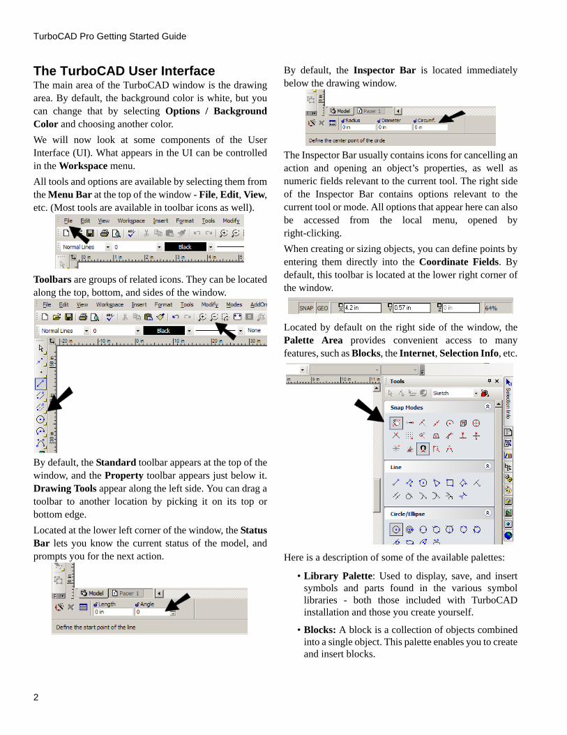
The Program Setup pages contain general options thatapply to TurboCAD all the time, not just for the currentdrawing. These pages can be accessed from the Optionsmenu, or from the flyout icon on the Standard toolbar.
The following are the available Program Setup pages:
• General Setup: Sets file opening and savingparameters, as well as user information.
• Desktop: Controls what appears on the window.
• Preference: General program options, such as cursorshape, axis color, zoom factor, and display ofcoordinate system icons.
• Toolbars and Menu: Usage and appearance oftoolbars and menus, plus access to customizationoptions for toolbars, menus, and keyboard shortcuts.
• Auto-Naming: Controls how groups, blocks, andsymbols are named.
• File Locations: Enables you to specify the folderswhere TurboCAD places several types of programfiles.
• Symbol Libraries: Displays the folders containingsymbols.
• Colors: Enables you to add, modify, or delete colorsfrom the TurboCAD palette.
• Warning Dialogs: Controls the display ofTurboCAD warning messages.
Drawing Setup pages are file-specific options, which areonly valid for the current file. They can be accessed fromthe Options menu, or from the flyout icon on theStandard toolbar.
The following are the available Drawing Setup pages:
• Display Options: Options for adjusting the qualityand redraw speed of the display, and options fordisplaying block attribute values.
• Grid Options: Controls the grid type, size, anddisplay.
• Advanced Grid Options: Advanced controls for thefrequency and locations of grid lines.
• Space Units: Controls for setting units in Model andPaper Space.
• Angle Options: Controls the measurement anddisplay of angles, as well as control over the Orthoangle.
• Layers: Layers can be used for placing objectsaccording to individual categories, and can be used tochange which objects are visible.
• Line Styles: View predefined line styles, modify ordelete them, and create new ones.
• Background Color: Changes the background color,which is white by default.
• Print Style Table: Select the print styles you want inyour drawing.

TurboCAD Pro Getting Started Guide
4
2D ProjectThis exercise will get you familiar with many of thecommonly-used 2D drawing tools.
Drawing Lines1. Start by displaying the grid. From the Standard
toolbar along the top of the window, click Show/Hide Grid.
2. The grid appears, with lines 1/2” apart. You can change grid spacing and colors by selecting Options / Grid. If rulers are displayed (Workspace / Rulers), you can see the measurements.
3. The first tool we will use is Line. From the Drawing Tools toolbar (along the left side), make sure Line is active. If it is not, click the icon to activate it.
NOTE: You can access any tool from the menu as well. For Line, select Insert / Line / Single.
4. Before clicking the first point, look at the Coordinates Field in the lower right corner of the window. Move your mouse around, and you can see the coordinates of the cursor location update dynamically.
5. Click anywhere to place the first point, and move the cursor toward a second point, but do not click yet.
6. Look in the Inspector Bar, in the lower left corner of the window. As you move your cursor, the Length and Angle of the line update.
7. Click anywhere to place the second point of the line.
8. For the next object, we will use snaps. Snaps enable you to place the cursor on an exact point, preventing you from having to approximate a point’s location.
9. To display the Snap Modes toolbar, right-click in the blank, gray space on any toolbar. From the list, select Snap Modes. Then close the Customize window.
10. The Snap Modes toolbar should appear along the top of the window. Click Grid. (A snap is enabled when it appears pressed in, and you can click a snap again to disable it.)
11. Also make sure Show Magnetic Point is enabled. This means that the nearest snap point will be marked when the cursor is close to it.
Version 15
5
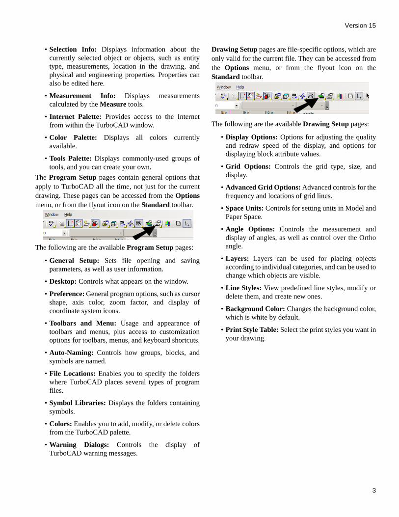
12. Finally, turn off No Snap, located at the top of the toolbar. If this is on, the other snaps will not work.
13. If any other snaps are active, turn them off.
NOTE: Snaps can also be set by selecting Modes / Snaps.
14. Now look to the left of the Coordinate Fields. The SNAP button should be on (if it is grayed out, click it to enable it). SNAP enables you to quickly turn on / off all permanent snaps, and when off, whatever snaps you set on the Snap Modes toolbar will not work.
TIP: If you right-click on the SNAP or GEO (geometric aids) button, you will see a window in which you can set permanent snaps. This is equivalent to using the Snap Modes toolbar.
15. With the Grid snap on, you can move your cursor in the drawing area and see the magnetic point whenever you are on or near a grid point.
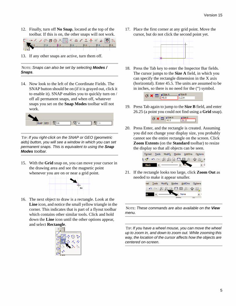
16. The next object to draw is a rectangle. Look at the Line icon, and notice the small yellow triangle in the corner. This indicates that is part of a flyout toolbar which contains other similar tools. Click and hold down the Line icon until the other options appear, and select Rectangle.
17. Place the first corner at any grid point. Move the cursor, but do not click the second point yet.
18. Press the Tab key to enter the Inspector Bar fields. The cursor jumps to the Size A field, in which you can specify the rectangle dimension in the X axis (horizontal). Enter 45.5. The units are assumed to be in inches, so there is no need for the (“) symbol.
19. Press Tab again to jump to the Size B field, and enter 26.25 (a point you could not find using a Grid snap).
20. Press Enter, and the rectangle is created. Assuming you did not change your display size, you probably cannot see the entire rectangle on the screen. Click Zoom Extents (on the Standard toolbar) to resize the display so that all objects can be seen.
21. If the rectangle looks too large, click Zoom Out as needed to make it appear smaller.
NOTE: These commands are also available on the View menu.
TIP: If you have a wheel mouse, you can move the wheel up to zoom in, and down to zoom out. While zooming this way, the location of the cursor affects how the objects are centered on-screen.
TurboCAD Pro Getting Started Guide
6
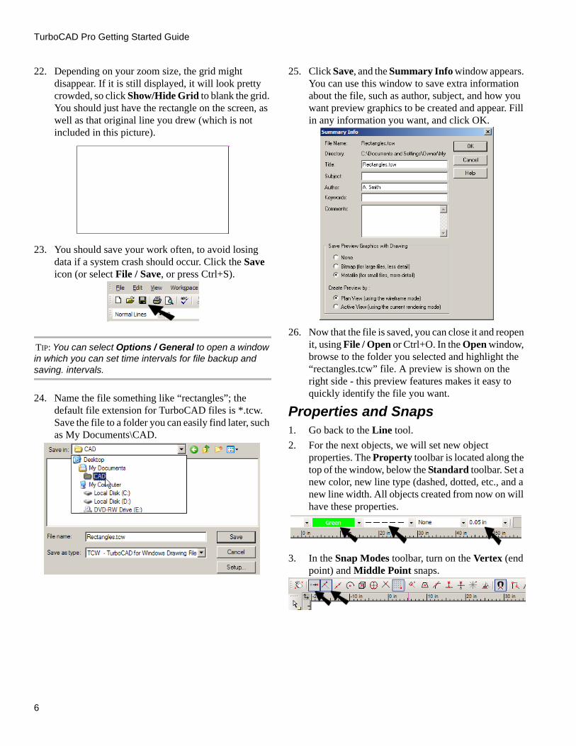
22. Depending on your zoom size, the grid might disappear. If it is still displayed, it will look pretty crowded, so click Show/Hide Grid to blank the grid. You should just have the rectangle on the screen, as well as that original line you drew (which is not included in this picture).
23. You should save your work often, to avoid losing data if a system crash should occur. Click the Save icon (or select File / Save, or press Ctrl+S).
TIP: You can select Options / General to open a window in which you can set time intervals for file backup and saving. intervals.
24. Name the file something like “rectangles”; the default file extension for TurboCAD files is *.tcw. Save the file to a folder you can easily find later, such as My Documents\CAD.
25. Click Save, and the Summary Info window appears. You can use this window to save extra information about the file, such as author, subject, and how you want preview graphics to be created and appear. Fill in any information you want, and click OK.
26. Now that the file is saved, you can close it and reopen it, using File / Open or Ctrl+O. In the Open window, browse to the folder you selected and highlight the “rectangles.tcw” file. A preview is shown on the right side - this preview features makes it easy to quickly identify the file you want.
Properties and Snaps1. Go back to the Line tool. 2. For the next objects, we will set new object
properties. The Property toolbar is located along the top of the window, below the Standard toolbar. Set a new color, new line type (dashed, dotted, etc., and a new line width. All objects created from now on will have these properties.
3. In the Snap Modes toolbar, turn on the Vertex (end point) and Middle Point snaps.
Version 15
7
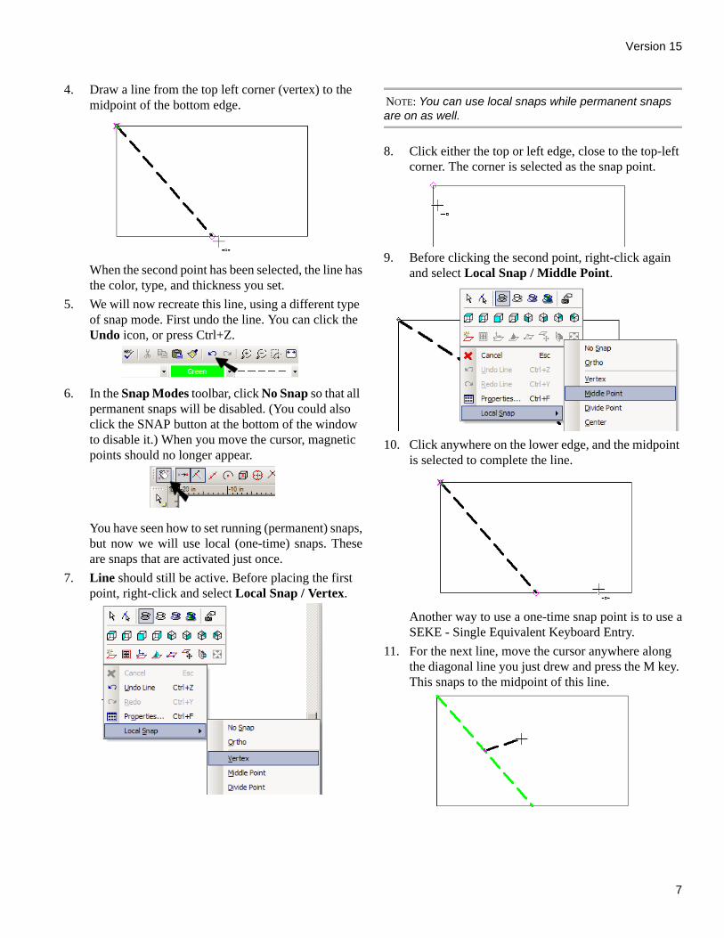
4. Draw a line from the top left corner (vertex) to the midpoint of the bottom edge.
When the second point has been selected, the line hasthe color, type, and thickness you set.
5. We will now recreate this line, using a different type of snap mode. First undo the line. You can click the Undo icon, or press Ctrl+Z.
6. In the Snap Modes toolbar, click No Snap so that all permanent snaps will be disabled. (You could also click the SNAP button at the bottom of the window to disable it.) When you move the cursor, magnetic points should no longer appear.
You have seen how to set running (permanent) snaps,but now we will use local (one-time) snaps. Theseare snaps that are activated just once.
7. Line should still be active. Before placing the first point, right-click and select Local Snap / Vertex.
NOTE: You can use local snaps while permanent snaps are on as well.
8. Click either the top or left edge, close to the top-left corner. The corner is selected as the snap point.
9. Before clicking the second point, right-click again and select Local Snap / Middle Point.
10. Click anywhere on the lower edge, and the midpoint is selected to complete the line.
Another way to use a one-time snap point is to use aSEKE - Single Equivalent Keyboard Entry.
11. For the next line, move the cursor anywhere along the diagonal line you just drew and press the M key. This snaps to the midpoint of this line.

TurboCAD Pro Getting Started Guide
8
12. Now move to either the top or right edge, near the corner, and press V. This snaps to the endpoint of the line.
Editing 2D GeometryThe next step is to trim lines to get one closed chain. Atthis point, the rectangle cannot be used to trim otherobjects, because it is one object comprised of foursub-objects. The rectangle must be broken down into itsindividual parts first.
1. Activate the Select tool, located at the top of the Drawing Tools toolbar. (Or from the menu, select Edit / Select.)
2. Click the rectangle to select it. All four lines are contained in the selection box.
3. While the rectangle is selected, click Explode (or select Format / Explode). This icon is near the bottom of the Drawing Tools toolbar. If you cannot see it, click the small arrow at the bottom of the toolbar to see the remaining icons.
4. Click outside the rectangle to deselect it, and select the rectangle again. Now only the segment you clicked is selected.
5. Open the Modify flyout toolbar and select Trim.
NOTE: All tools on this toolbar can be found in the Modify menu.
6. When in doubt about what steps to perform, you can always look in the Status Bar - located below the Inspector Bar at the lower left corner. The first step in the Trim tools is to define the cutting edge.
7. Select the second diagonal line you drew to be the cutting edge.
Version 15
9
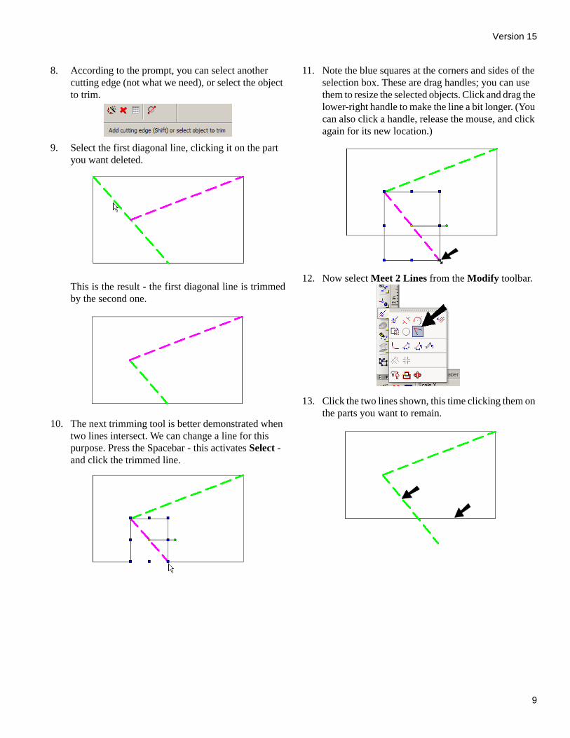
8. According to the prompt, you can select another cutting edge (not what we need), or select the object to trim.
9. Select the first diagonal line, clicking it on the part you want deleted.
This is the result - the first diagonal line is trimmedby the second one.
10. The next trimming tool is better demonstrated when two lines intersect. We can change a line for this purpose. Press the Spacebar - this activates Select - and click the trimmed line.
11. Note the blue squares at the corners and sides of the selection box. These are drag handles; you can use them to resize the selected objects. Click and drag the lower-right handle to make the line a bit longer. (You can also click a handle, release the mouse, and click again for its new location.)
12. Now select Meet 2 Lines from the Modify toolbar.
13. Click the two lines shown, this time clicking them on the parts you want to remain.

TurboCAD Pro Getting Started Guide
10
Here is the result - both lines were trimmed to oneanother.
TIP: We have just used several tools from the Modify toolbar. If you often use a particular toolbar, you can keep it permanently displayed in its entirety. Right-click in any toolbar area and select the toolbar you want to see, in this case the Modify toolbar.
14. Activate Select once again and press Shift so that you can select multiple objects. Click both lines shown, and they are both selected. (When using Shift, you can also click a selected object to deselect it.)
15. Press the Delete key to erase these lines.
The remaining four lines are each separate objects,which you can verify by selecting each line one byone.
16. Make sure no lines are selected (click away from an object to deselect it). To join the lines into one object, select the menu option Modify / Join Polyline.
17. A polyline is a chain of connected line and arc segments, that is considered to be a single object (like the rectangle you created). A polyline can be open or closed.
18. You could select each line one by one, but it is easier if you select Auto Joining. This option can be activated by the icon on the Inspector Bar or in the local (right-click) menu.
19. Click any line, and the chain is automatically identified. We now have a single object, which has uniform properties - line type, line weight, and color.
20. Use Select to select the polyline - it is one object.
To change its properties, click the Properties icon inthe Inspector Bar. (You could also select Format /Properties or press Ctrl+F.)

Version 15
11
In the Properties window, open the Pen page. Setthe line type to Continuous, and change the color andweight. This does not affect the settings in theProperty toolbar, it only changes the properties ofwhatever is selected.
Click OK to close the Properties window, and hereis the modified polyline (click outside the polyline todeselect it).
TIP: You can set properties in advance for a group of tools - i.e. all tools located on the same toolbar. For example, you can right-click on the current icon in the Line toolbar. This opens the Properties window. Once you modify the properties, all objects created via the Line toolbar (rectangles, polylines, polygons, etc.) will now share these properties.
21. For another way to open the Properties window, activate Select and double-click the polyline. Now open the Brush page. Here you can set the pattern, or solid-colored fill, that fills a closed shape. Select a brick pattern and reduce the scale.
NOTE: Brush patterns can also be set on the Property toolbar.
Here is the result:

TurboCAD Pro Getting Started Guide
12
Creating a Polyline1. Start a new file by clicking the New icon (or select
File / New, or press Ctrl+N).
2. Select New from Scratch.
TIP: Another useful option in the above window is Page Setup Wizard. This is a step-by-step guide for setting up your file. You can set units, precision, paper size / orientation, printing scale, and viewports (used in paper space).
3. Start by changing the units. Select Options / Space Units and set the units to Metric, with mm as the base unit.
4. Click OK, and the rulers should now show mm measurements.
5. Open the Line toolbar and select Polyline.
6. For the first point, press Shift + Tab to enter the Coordinate fields. This way you can start the object at a specific point in space. Enter 5.5 for X, and press Tab and enter 2.5 for Y. Press Enter.
7. The polyline’s first point is now set at point (5.5mm, 2.5mm). Do not select more points yet.
8. Until now we have been using Absolute coordinates, but if you know an object’s measurements already, it is easier to enter distances from the last point, rather than entering exact coordinates each time. Therefore, use the icon on the Standard toolbar to switch to Relative coordinates
NOTE: Coordinate systems can also be changed via the Modes menu.
Now a red circle marks the last specified point.
9. For the next point, return to the Coordinate fields. Now the X and Y fields have a +/- sign, indicating that distances you enter here are measured relative to the last point you set. Enter 4 for X and 0 for Y to create a line 4 mm long to the right (in the positive X direction).
Version 15
13
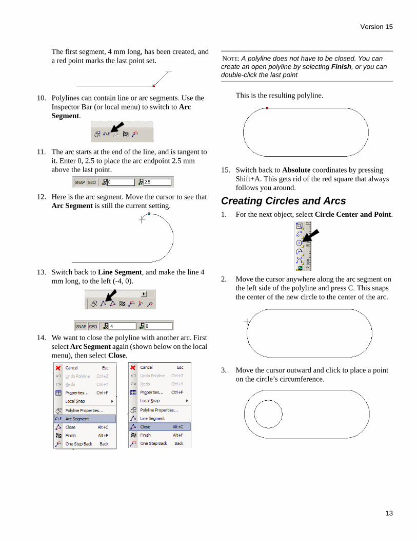
The first segment, 4 mm long, has been created, anda red point marks the last point set.
10. Polylines can contain line or arc segments. Use the Inspector Bar (or local menu) to switch to Arc Segment.
11. The arc starts at the end of the line, and is tangent to it. Enter 0, 2.5 to place the arc endpoint 2.5 mm above the last point.
12. Here is the arc segment. Move the cursor to see that Arc Segment is still the current setting.
13. Switch back to Line Segment, and make the line 4 mm long, to the left (-4, 0).
14. We want to close the polyline with another arc. First select Arc Segment again (shown below on the local menu), then select Close.
NOTE: A polyline does not have to be closed. You can create an open polyline by selecting Finish, or you can double-click the last point
This is the resulting polyline.
15. Switch back to Absolute coordinates by pressing Shift+A. This gets rid of the red square that always follows you around.
Creating Circles and Arcs1. For the next object, select Circle Center and Point.
2. Move the cursor anywhere along the arc segment on the left side of the polyline and press C. This snaps the center of the new circle to the center of the arc.
3. Move the cursor outward and click to place a point on the circle’s circumference.

TurboCAD Pro Getting Started Guide
14
4. Select the circle, and move the cursor over the small yellow dot at the center. This dot is the reference point, which can be used to move the selected objects. Click this point.
5. Move the reference point so that it is concentric with the arc on the right side. You can use the C key as before, or use a local snap, or even set the Center snap on the Snap Modes toolbar.
TIP: When using the Snap Modes toolbar, keep in mind that these snaps stay active even when you might not want them. If you are having trouble selecting a certain point, check the Snap Modes toolbar to make sure the right snaps are set.
6. Now for an arc - select Arc Center and Radius.
7. Place the arc center at the midpoint of the lower line, and click again to set the radius.
8. The next two clicks set the start and end angles. Arcs are created in the counter-clockwise direction. Keep Shift pressed, which puts you in Ortho mode. This
means you can only move the cursor horizontally or vertically. Start the arc by clicking to the right (zero degrees).
9. End the arc by clicking to the left (180 degrees).
TIP: Ortho mode can also be set on the Snap Modes toolbar.
10. The next tool is Arc Start / End / Included, located on the Arc flyout toolbar.
11. Use Vertex snaps to place the start and end points at the ends of the upper line. Click again to set the arc bulge.
Version 15
15
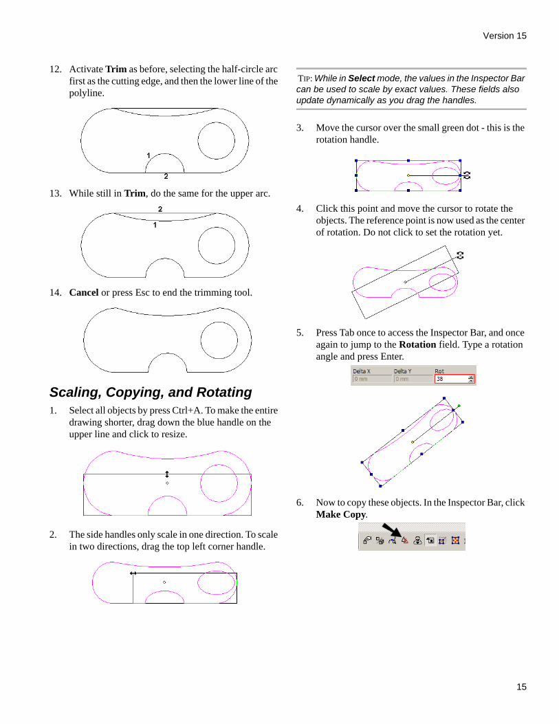
12. Activate Trim as before, selecting the half-circle arc first as the cutting edge, and then the lower line of the polyline.
13. While still in Trim, do the same for the upper arc.
14. Cancel or press Esc to end the trimming tool.
Scaling, Copying, and Rotating1. Select all objects by press Ctrl+A. To make the entire
drawing shorter, drag down the blue handle on the upper line and click to resize.
2. The side handles only scale in one direction. To scale in two directions, drag the top left corner handle.
TIP: While in Select mode, the values in the Inspector Bar can be used to scale by exact values. These fields also update dynamically as you drag the handles.
3. Move the cursor over the small green dot - this is the rotation handle.
4. Click this point and move the cursor to rotate the objects. The reference point is now used as the center of rotation. Do not click to set the rotation yet.
5. Press Tab once to access the Inspector Bar, and once again to jump to the Rotation field. Type a rotation angle and press Enter.
6. Now to copy these objects. In the Inspector Bar, click Make Copy.
TurboCAD Pro Getting Started Guide
16
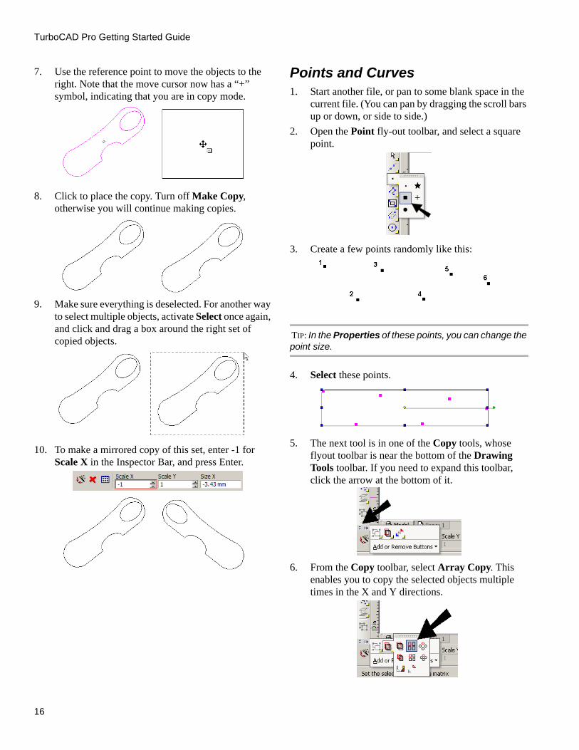
7. Use the reference point to move the objects to the right. Note that the move cursor now has a “+” symbol, indicating that you are in copy mode.
8. Click to place the copy. Turn off Make Copy, otherwise you will continue making copies.
9. Make sure everything is deselected. For another way to select multiple objects, activate Select once again, and click and drag a box around the right set of copied objects.
10. To make a mirrored copy of this set, enter -1 for Scale X in the Inspector Bar, and press Enter.
Points and Curves1. Start another file, or pan to some blank space in the
current file. (You can pan by dragging the scroll bars up or down, or side to side.)
2. Open the Point fly-out toolbar, and select a square point.
3. Create a few points randomly like this:
TIP: In the Properties of these points, you can change the point size.
4. Select these points.
5. The next tool is in one of the Copy tools, whose flyout toolbar is near the bottom of the Drawing Tools toolbar. If you need to expand this toolbar, click the arrow at the bottom of it.
6. From the Copy toolbar, select Array Copy. This enables you to copy the selected objects multiple times in the X and Y directions.

Version 15
17
7. Press Tab to enter the Inspector Bar, and enter values like this. Adjust your Y Step value as needed to get a reasonable spacing - the preview line will update as you change the value. Enter three rows and one column.
8. Press Enter. You should have three rows (and one column) of the selected points.
9. Now find the Curves toolbar and select the first tool: Spline by Control Points. This draws a spline using points as a guide, but the curve does not actually pass through the points.
10. Click the points in the top set, one by one. If you want to snap to them, use the V key, or turn the Vertex snap on.
11. From the Inspector Bar or local menu, select Finish. (You can also press Alt+F.)
The spline looks like this - it passes through the firstand last points only, and the other points guide itscurvature.
NOTE: If you had selected Close instead of Finish, the spline would make a loop, and would not pass through any points. Also, if you want to finish an open spline, you can double-click its last point.
12. For the second set of points, activate the second curve tool - Spline by Fit Points.
13. Select the points in order like before. This time the spline does pass through the selected points.
14. For the third and last set, use Bezier.
15. This creates a curve similar to Spline by Fit Points, but with different tangency and curvature properties.

TurboCAD Pro Getting Started Guide
18
Selection Info PaletteMenu: View / Selection Info Displays information about the currently selected objector objects. You can also change properties of objects here.
1. Create few objects, then select them all.
All types of objects are listed in the upper window ofthe Selection Info Palette.
2. Highlight any item, such as the polyline. If the Highlighting icon is activated. . .
. . . the object will also be highlighted onscreen.
3. For the highlighted object, its properties are listed in the lower section of the palette. You can change colors, line widths, etc., as well as geometric
properties such as radius or point coordinates. (If a field cannot be edited, it will be grayed out.) In this example, the Line color of circle was changed.
The change is made automatically.
NOTE: For 3D ACIS objects, physical properties are not automatically listed. Click the Physical Metrics icon in the palette toolbar if you want to see engineering properties (volume, moments of inertia, etc.).
Version 15
19
Working in 3DThe rest of the guide will give a basic overview of somethings you can do in 3D.
3D ViewsWhile working in 3D, there are many ways to change howyou view your drawing. Views are seen by the “camera” -equivalent to your eye. The camera is located in a specificplace and faces a specific direction. There are several standard orthographic and isometricviews, and if you need additional perspective you canchange how the camera is oriented. You can move thecamera using the Move Camera commands, anddynamically examine the model using the Walk Throughtools. To save and display additional views, you can createcamera objects.
TIP: If you use a wheel mouse, keep the middle mouse button pressed, and drag the cursor around the screen to dynamically rotate the model.
The ten standard views can be accessed from theStandard toolbar, or from the View / Camera menu. Youcan also display this toolbar separately by right-clickingin the toolbar area and selecting Standard Views.
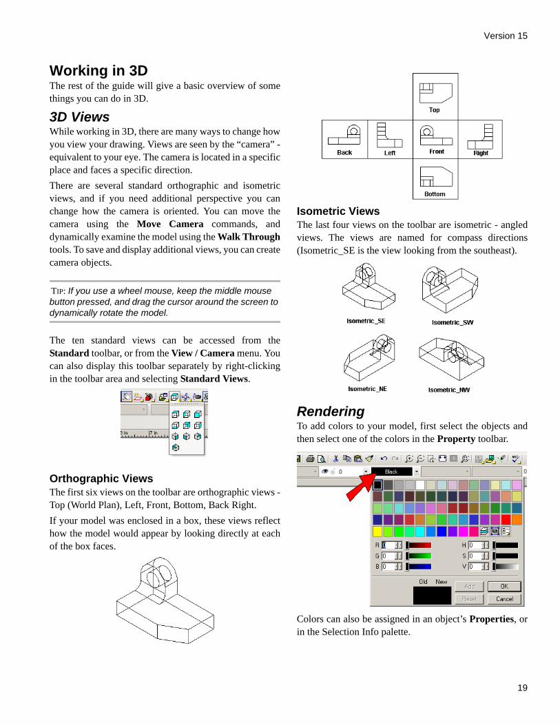
Orthographic ViewsThe first six views on the toolbar are orthographic views -Top (World Plan), Left, Front, Bottom, Back Right. If your model was enclosed in a box, these views reflecthow the model would appear by looking directly at eachof the box faces.
Isometric ViewsThe last four views on the toolbar are isometric - angledviews. The views are named for compass directions(Isometric_SE is the view looking from the southeast).
RenderingTo add colors to your model, first select the objects andthen select one of the colors in the Property toolbar.
Colors can also be assigned in an object’s Properties, orin the Selection Info palette.
TurboCAD Pro Getting Started Guide
20
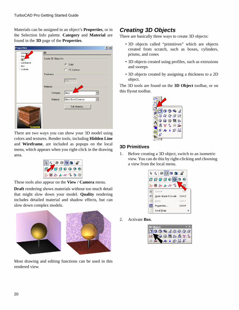
Materials can be assigned in an object’s Properties, or inthe Selection Info palette. Category and Material arefound in the 3D page of the Properties.
There are two ways you can show your 3D model usingcolors and textures. Render tools, including Hidden Lineand Wireframe, are included as popups on the localmenu, which appears when you right-click in the drawingarea.
These tools also appear on the View / Camera menu.Draft rendering shows materials without too much detailthat might slow down your model. Quality renderingincludes detailed material and shadow effects, but canslow down complex models.
Most drawing and editing functions can be used in thisrendered view.
Creating 3D ObjectsThere are basically three ways to create 3D objects:
• 3D objects called “primitives” which are objectscreated from scratch, such as boxes, cylinders,prisms, and cones
• 3D objects created using profiles, such as extrusionsand sweeps
• 3D objects created by assigning a thickness to a 2Dobject.
The 3D tools are found on the 3D Object toolbar, or onthis flyout toolbar.
3D Primitives1. Before creating a 3D object, switch to an isometric
view. You can do this by right-clicking and choosing a view from the local menu.
2. Activate Box.

Version 15
21
3. Click two opposite corners for the rectangular base.The third click sets the height of the box.
You can also enter the length, width, and height in theInspector Bar. (You can press Tab to jump to theInspector Bar.)
4. Next, activate Sphere.
5. Click the center point, then a point on the outside.
6. To change the way the sphere is displayed, select Options / Display, and check Draw form-building edges.
7. In the same Drawing Setup window, open the ACIS page, and make sure Degenerative Faceting is not checked.
8. This is how the sphere should look:
3D Profile Objects1. Start with a profile like this, which you can create
using the Polyline tool.
2. Activate Simple Extrude.
3. Click the profile, then move the mouse to create the 3D object.

TurboCAD Pro Getting Started Guide
22
NOTE: You can also extrude an open profile, which would result in a 3D surface.
4. Switch to Hidden Line mode.
Now the hidden edges are not visible.
2D Object with Thickness1. To make this object, start with the same 2D polyline
used for Simple Extrude.
2. Using the Select tool, double-click on the polyline to open its Properties. On the 3D page, enter a value for Thickness. And while you’re here on this page, also select a Category and Material.
Here is the resulting object, shown in Quality rendermode.
Version 15
23
Combining 3D ObjectsBoolean operations can be used to add, subtract, orintersect 3D objects.
3D AddMenu: Modify / 3D Boolean Operations / 3D Add
Combines two 3D objects into one object. Anyoverlapping volume is removed.Select two objects to combine, and the second object isjoined to the first object. Selection order is important,because the new object will have all the properties of thefirst object selected, such as layer and material.
The resulting object is one object.
The selected objects do not have to overlap. If youcombine non-overlapping objects, they will still becombined into one object.
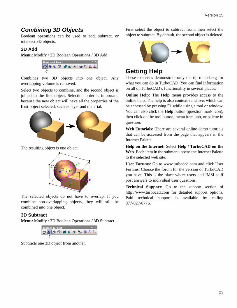
3D SubtractMenu: Modify / 3D Boolean Operations / 3D Subtract
Subtracts one 3D object from another.
First select the object to subtract from, then select theobject to subtract. By default, the second object is deleted.
Getting HelpThese exercises demonstrate only the tip of iceberg forwhat you can do in TurboCAD. You can find informationon all of TurboCAD’s functionality in several places:Online Help: The Help menu provides access to theonline help. The help is also context-sensitive, which canbe accessed by pressing F1 while using a tool or window.You can also click the Help button (question mark icon),then click on the tool button, menu item, tab, or palette inquestion.Web Tutorials: There are several online demo tutorialsthat can be accessed from the page that appears in theInternet Palette.Help on the Internet: Select Help / TurboCAD on theWeb. Each item in the submenu opens the Internet Paletteto the selected web site.User Forums: Go to www.turbocad.com and click UserForums. Choose the forum for the version of TurboCADyou have. This is the place where users and IMSI staffpost answers to individual user questions.Technical Support: Go to the support section ofhttp://www.turbocad.com for detailed support options.Paid technical support is available by calling877-827-8776.

TurboCAD Pro Getting Started Guide
24