TurboCAD Deluxe V21 - Caboose SAMPLE - Textual Deluxe V21 - Caboose SAMPLE.pdf · TurboCAD Deluxe...
20
Donald B. Cheke www.textualcreations.ca 1 TurboCAD Deluxe V21 – Caboose Donald B. Cheke
Transcript of TurboCAD Deluxe V21 - Caboose SAMPLE - Textual Deluxe V21 - Caboose SAMPLE.pdf · TurboCAD Deluxe...

Donald B. Cheke www.textualcreations.ca
1
TurboCAD Deluxe V21 – Caboose
Donald B. Cheke

Donald B. Cheke www.textualcreations.ca
2
All rights reserved No part of this document may be reproduced, copied, stored on a retrieval system or transmitted in any form without written permission from the author. The purchaser may, however, print one copy of the document to paper and may make one backup copy of the downloaded material for personal safe keeping. Limitation of Liability While every effort has been taken in the preparation and the writing of this document the author assumes no responsibility for errors and/or omissions nor for the uses of the material and the decisions based on such use. No warranties are made, express or implied with regard to either the contents of the document, its merchant ability or fitness for a particular purpose. The author should not be liable for direct, indirect, special, incidental or consequential damages arising out of the use or inability to use the contents of this document. Special Note All of the work presented within this tutorial is based on TurboCAD Deluxe V21 (64-Bit). Although users of previous versions are welcome to try the tutorial it cannot be stated what results will be achieved. Many changes, some subtle and others not so subtle, are made with each program revision. Although many steps and directions would be generic some may not be. The same can be said for tools between versions. Older versions may not have the same tools as Deluxe V21 and if the same tools are available the tools themselves may have been revised and hence, work in a different manner than they previously did.
Copyright © 2014 Donald B. Cheke TurboCAD is a registered trademark of IMSI/Design.
Published by: Donald B. Cheke Saskatoon, SK Canada Visit: www.textualcreations.ca

Donald B. Cheke www.textualcreations.ca
3
Table of Contents Table of Contents ......................................................................................................................................................... 3 Introduction .................................................................................................................................................................. 4 Setup .............................................................................................................................................................................. 6 2D Wheel, Hub and Track Profiles .......................................................................................................................... 24 3D Wheels and Hubs ................................................................................................................................................. 44 2D Wheel Carriage Profiles ...................................................................................................................................... 47 3D Wheel Carriage .................................................................................................................................................... 69 2D Bolster Profile to 3D Bolster .............................................................................................................................. 87 3D Axels ...................................................................................................................................................................... 96 2D Main Car Profiles .............................................................................................................................................. 103 3D Main Car ............................................................................................................................................................. 117 2D Car End Entry ..................................................................................................................................................... 131 3D Car End Entry ..................................................................................................................................................... 141 3D Windows & Widow Frames ............................................................................................................................. 147 End Gear – 2D/3D Stairs ....................................................................................................................................... 159 End Gear – 2D/3D Wheel Brake .......................................................................................................................... 174 End Gear – 2D/3D Ladder .................................................................................................................................... 193 End Gear – 2D/3D Hand Rail ............................................................................................................................... 201 End Gear – 2D/3D Coupler ................................................................................................................................... 207 Car Side Windows ................................................................................................................................................... 223 Far End Components .............................................................................................................................................. 234 2D Cupola Profiles .................................................................................................................................................. 237 3D Cupola ................................................................................................................................................................ 242 Cupola Windows ..................................................................................................................................................... 252 2D/3D Chimney ...................................................................................................................................................... 259 Signage ..................................................................................................................................................................... 265 Panel Ribs ................................................................................................................................................................ 271 3D Track ................................................................................................................................................................... 278 Materials Application ............................................................................................................................................. 282 Ground Plane (Shadow Catcher) .......................................................................................................................... 304 Named Views ........................................................................................................................................................... 308 Render Scene Luminance ..................................................................................................................................... 312 Render Scene Environment .................................................................................................................................. 316 Saving the Rendered Image ................................................................................................................................. 324

Donald B. Cheke www.textualcreations.ca
4
Introduction There is something romantic about the Caboose. It conjures up all kinds of feeling about the past, about solitude and life on the rails. Many folks have a fascination with railroading and the author is no exception, so a tutorial to create such a thing seemed the perfect way to introduce new users to TurboCAD. An HO scale wide vision Caboose, purchased from the local hobby store, will be used as the basis of the tutorial. The reader is not required to purchase one, as the author will measure and provide the required dimensions.
Digital calipers with the model. Within this comprehensive tutorial the reader will be led through each keystroke to produce all components of the caboose and track that is illustrated on the cover of the tutorial. The reader will learn how to create each object by manipulating 2D profiles and 3D primitive shapes. The reader will learn how to set up their drawing, how to insert standard lighting and how utilize render scene luminance. The reader will learn how to establish a render scene environment and the reader will learn how to render their drawing and save it in a high resolution image format. This tutorial is in no way intended to teach mechanical design but rather it is intended to teach the use of some of the tools that TurboCAD has to offer and to introduce the new user to a drawing methodology. The author feels confident that the techniques outlined within the tutorial can help lay the foundation for future successful TurboCAD drawing and illustration for even the newest user.
As with any technically advanced software, the user is generally faced with a steep learning curve. It is the hope of the author that the money and time spent working through a Textual Creations tutorial will help ease the learning and allow the reader to come away feeling confident that they made a wise decision. This tutorial will assume that the reader has TurboCAD Deluxe V21. There are many ways to approach a project and it is likely that each person using the program would proceed in very different ways, so be open to alternative methods as experience builds. This tutorial assumes that the beginner has studied the desktop to some degree and can locate most of the tools. Since there are endless desktop configurations that can be set up in TurboCAD the author has opted to illustrate the required tools with the TurboCAD Classic user interface with its Office 2003 theme and the default toolbars in their undocked format.

Donald B. Cheke www.textualcreations.ca
5
Please remember that any supplied images and files are for use within the tutorial only and may not be shared or sold to others. Place all tutorial images in a permanent location on the hard drive. For those working through the tutorial in pre-V18 versions please note that most of the functions described in the tutorial, as being on the Modify menu, were on the Format menu in previous versions of the program. Lastly, the Copy in Place tool was reintroduced into TurboCAD V18 as a permanent tool. Users who don't have this new tool will need to use the Make Copy method. That is to select the object to copy in place, select the Make Copy tool to turn it on, tab into the first field on the Inspector Bar – but don't change anything – simply press Enter. Select the Make Copy tool again to turn it off.

Donald B. Cheke www.textualcreations.ca
24
2D Wheel, Hub and Track Profiles The scale model will be, for the most part, created from the ground up beginning with the track. The image below illustrates what is being worked towards in this section.
Switch to Left view. Select Plane by Active View from the Workplane toolbar.
Select the Rectangle tool from the Line toolbar.
Place the cursor in the drawing area over one of the grid intersection and G SEKE snap (press the G key on the keyboard) the first point of the railroad tie profile to the grid. Move the cursor in a right upwardly direction for a short distance and then Tab into the Inspector Bar and enter 28.5 in the Size A field and 1.8 in the Size B field. Press Enter.
Press the Space Bar to exit the tool. Select (left mouse click) the rectangle that was just created. Tab into the Inspector Bar and enter 0 in the X, Y and Z Position fields. Press Enter. This will move the entity to a common location in the drawing for all readers.
Donald B. Cheke www.textualcreations.ca
42
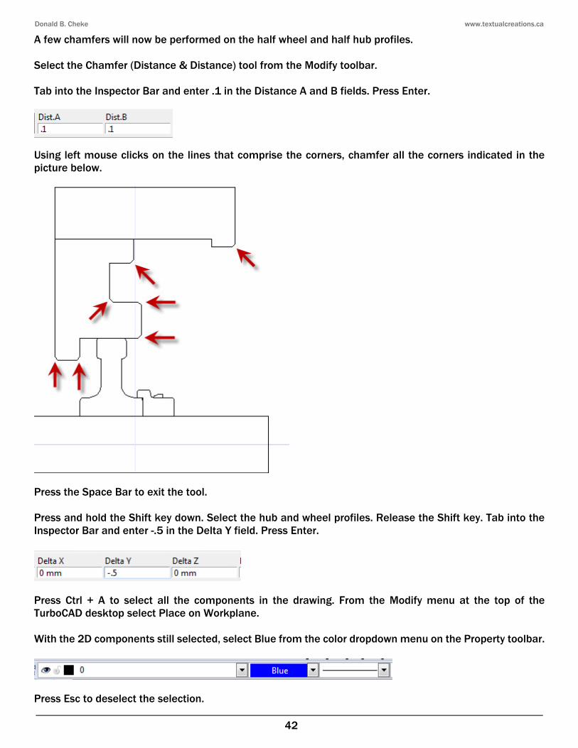
A few chamfers will now be performed on the half wheel and half hub profiles. Select the Chamfer (Distance & Distance) tool from the Modify toolbar. Tab into the Inspector Bar and enter .1 in the Distance A and B fields. Press Enter.
Using left mouse clicks on the lines that comprise the corners, chamfer all the corners indicated in the picture below.
Press the Space Bar to exit the tool. Press and hold the Shift key down. Select the hub and wheel profiles. Release the Shift key. Tab into the Inspector Bar and enter -.5 in the Delta Y field. Press Enter.
Press Ctrl + A to select all the components in the drawing. From the Modify menu at the top of the TurboCAD desktop select Place on Workplane. With the 2D components still selected, select Blue from the color dropdown menu on the Property toolbar.
Press Esc to deselect the selection.

Donald B. Cheke www.textualcreations.ca
43

Donald B. Cheke www.textualcreations.ca
63
Using left mouse clicks on the lines that comprise the corners, fillet the two small corners as indicated in the picture below.
Tab into the Inspector Bar and enter 1 in the Radius field. Press Enter.
Using left mouse clicks on the lines that comprise the corners, fillet the two corners as indicated in the picture below.
Press the Space Bar to exit the tool. The complete half wheel carriage profile will now be mirror copied and then mock coil profiles will be created within the central area. Press and hold the Shift key down. Select the half wheel carriage profile and the rounded triangle. Release the Shift key.

Donald B. Cheke www.textualcreations.ca
64
Select the Mirror Copy tool from the Copy toolbar. V SEKE snap the bottom left corner of the selection to define the first point of the mirroring line. Move the cursor to the top left corner of the selection and V SEKE snap to define the second point of the mirroring line. In progress below.
Press Esc to deselect the selection. The central area requires three coil springs that travel from the bottom of the opening upward to a point where they contact the bottom of the bolster. Simplified representations of springs will be used. Select the Rectangle tool from the Line toolbar. Left mouse click in an area below the carriage profiles to place the first point of the rectangle. Move the cursor in a right downwardly direction for a short distance and then Tab into the Inspector Bar and enter 1.5 in the Size A field and 3 in the Size B field. Press Enter.
Press the Space Bar to exit the tool. Select the rectangle that was just created. Press D SEKE and relocate (M SEKE) the reference point to the bottom line of the selection. In progress below.
Left mouse click on the reference point of the rectangle to pick it up. Move the cursor to the bottom of the central opening and V SEKE snap it in place as indicated in the picture below. In progress below.

Donald B. Cheke www.textualcreations.ca
99
Place the cursor by the edge of the central circle and C SEKE snap to define the first point of the mirroring line. Press and hold the Shift key down. Move the cursor upward a short distance and left mouse click to define the second point of the mirroring line. Release the Shift key. In progress below.
Press Esc to deselect the selection. Switch to Isometric SE view. Open the Design Director and create a new layer called Axel and then turn off all layers except layer 0.
Press and hold the Shift key down. Select the two axels. Release the Shift key. Assign the selection to the Axel layer. In progress below.

Donald B. Cheke www.textualcreations.ca
100
Select the Workplane by Facet tool from the Workplane toolbar. Move the cursor over the top of the central cylinder and when the top is highlighted left mouse click to assign the workplane. In progress below.
Select the larger red circle. From the Modify menu at the top of the TurboCAD desktop select Place on Workplane. The circle moves to the top of the cylinder.
Select Plane by World from the Workplane toolbar. Press Esc to deselect the selection. Press and hold the Shift key down. Select the three 3D objects. Release the Shift key.

Donald B. Cheke www.textualcreations.ca
141
3D Car End Entry Select the Simple Extrude tool from the 3D Object toolbar. Turn off the Two sided extrude option. Select the end wall profile as the object to extrude. Tab into the Inspector Bar and enter -.5 in the Height field. Press Enter. In progress below.
Select the central panel profile that was node edited as the object to extrude. Tab into the Inspector Bar and enter .5 in the Height field. Press Enter.
Select the other four profiles, one at a time, and extrude them into the car. Left mouse click when moved clearly through the end wall to define the extent of the extrusion.

Donald B. Cheke www.textualcreations.ca
142
Select the 3D Subtract tool from the Boolean & Facet toolbar. Select the back wall as the object to subtract from and then select the left window extrusion as the object to subtract. In progress below.

Donald B. Cheke www.textualcreations.ca
171
Press Ctrl + A to select all of the objects in the drawing area. Select the Suppress Hidden Line render tool on the Render toolbar to have a look so far at the back end.
Press Esc to deselect the selection. The floor needs to have two small boxes added to the ends.
Select the Wireframe tool render toolbar to end the render.
Select the Box tool from the 3D Object toolbar. Using three V SEKE snaps place a box on the right side as indicated in the pictures below. First V SEKE snap.

Donald B. Cheke www.textualcreations.ca
191
Tab into the Inspector Bar and type the minus sign in the Delta X field and then paste (Ctrl + V) the copied number in as well. Press Enter.
Create a new layer called Wheel Brake and turn it off.
Select and assign all the visible components to the new layer. The wheel brake needs to be move over to make room for the upcoming ladder. Turn on the Roof, Floor and Wheel Brake layers. Switch to Isometric NE view. Press Ctrl + L to open the Select by Layer dialogue. Select Wheel Brake and click OK.

Donald B. Cheke www.textualcreations.ca
192
With the wheel brake now selected, Tab into the Inspector Bar and enter 6.455 in the Delta Y field. Press Enter.

Donald B. Cheke www.textualcreations.ca
276
Turn off the Windows layer and turn on the Floor layer. Now the wall text, logo and ribs will be placed on the other side of the car. Press and hold the Shift key down. Select all the wall rib components, the text and the CN logo (16 objects). Release the Shift key. Press D SEKE and relocate (M SEKE) the reference point to upper middle line of the floor.
Select the Make Copy tool to turn it on. Tab into the Inspector Bar and enter 180 in the Z Rotation field. Press Enter.
Disengage the Make Copy tool. Press Esc to deselect the selection. Turn off all layers, except layer 0. Create three new layers, one called Signage, one called Chimney and one called Wall Ribs. Turn off the new layers.

Donald B. Cheke www.textualcreations.ca
294
Select the Wireframe tool to end the render. Turn off the visible 3D layers and then turn on the layers as illustrated below.
Press Ctrl + A to select all the visible objects. Open the Materials palette and the locate Gloss Paint category. Right mouse click over the Black A thumbnail and select Edit LightWorks Material.
Right mouse click the Black A and select Copy Material Here.
Enter Red A in the New Material dialogue and click OK.
Expand Red A in the window on the left and select the Pattern tab. Left mouse click on the color box to open the color menu. Enter an RGB of 175, 0, 0. Click OK.

Donald B. Cheke www.textualcreations.ca
295
Click OK to exit the Render Manager. Open the Materials palette. Locate the Gloss Paints category and then double click on the Red A thumbnail to apply the material. The blacked out thumbnail below is another bug in this version of TurboCAD. Double click on the new thumbnail to apply the material to the selection.
Select Quality Rendering tool on the Render toolbar. Allow the screen to render and then press Esc to deselect the selection.
Select the Wireframe tool to end the render.