Turbo Molecular Pump · Doc No. BTS-46E-000 Ver.05 2 Edwards Japan Limited 1 Introduction Turbo...
20
Doc No. BTS-46E-000 Ver.05 Turbo Molecular Pump STP-A1603 series Specification Edwards Japan Limited Pump Type - STP-A1603C - STP-A1603CV
Transcript of Turbo Molecular Pump · Doc No. BTS-46E-000 Ver.05 2 Edwards Japan Limited 1 Introduction Turbo...
Doc No. BTS-46E-000 Ver.05
Turbo Molecular Pump STP-A1603 series
Specification
Edwards Japan Limited
Pump Type - STP-A1603C - STP-A1603CV

Doc No. BTS-46E-000 Ver.05
Edwards Japan Limited 1
TABLE OF CONTENTS 1 Introduction ............................................................................................................................... 2
1.1 Application ................................................................................................................................. 2 1.2 Configuration .............................................................................................................................. 3
2 STP Pump ................................................................................................................................... 4 2.1 STP pump specification .............................................................................................................. 4 2.2 Precaution before installing the STP pump ................................................................................ 5
2.2.1 How to secure the STP pump .......................................................................................... 5 2.2.2 Purge gas for STP pump .................................................................................................. 6
3 STP control unit specification ...................................................................................................... 7 4 Power cable specification ........................................................................................................... 8 5 STP connection cable specification .............................................................................................. 8 6 TMS unit specification ................................................................................................................ 9
6.1 TMS connection cable ................................................................................................................ 9 6.2 TMS valve (with cable) ............................................................................................................... 9
7 STP pump detailed specification ............................................................................................... 10 7.1 Pumping speed graph ............................................................................................................... 10 7.2 Throughput graph (P-Q curve) ................................................................................................. 10 7.3 STP pump external views ......................................................................................................... 11
8 STP control unit detailed specification ...................................................................................... 14 8.1 I/O Remote ............................................................................................................................... 14 8.2 RS232/RS485 ............................................................................................................................ 15
9 Attachment component ........................................................................................................... 15 10 Accessory ................................................................................................................................. 15
PRECAUTIONS
1) No part of this documents may be reproduced and transmitted in any means without prior written permission from Edwards.
2) Edwards pursues a policy of continuing improvement in design and performance of this product. The right is, therefore, reserved to vary specifications and design without notice. Understand that the product you purchased and its contents including specifications described in this manual may differ.
Doc No. BTS-46E-000 Ver.05
Edwards Japan Limited 2
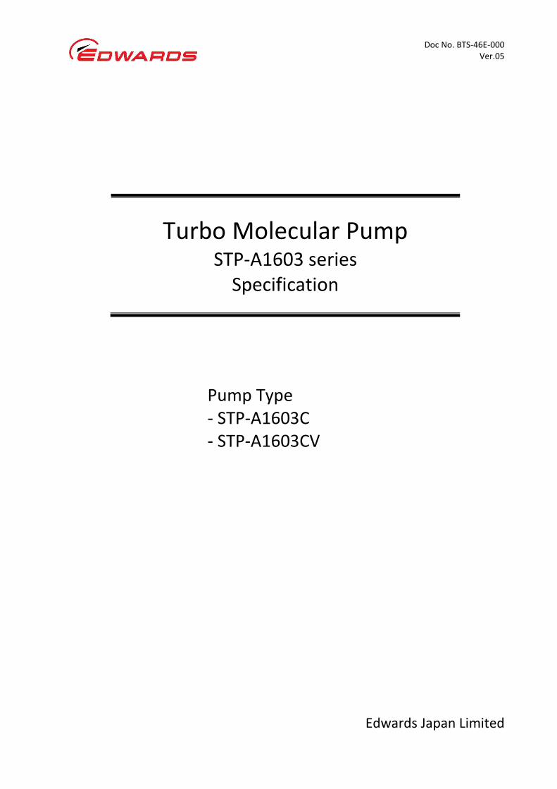
1 Introduction Turbo Molecular pump is one of the most important Vacuum Components in the most- advanced technologies field like Semiconductor and LCD manufacturing tools, high- energy physics, etc. This document describes the standard specification for the magnetically levitated turbo molecular pumps of STP-A1603C and STP-A1603CV.
STP-A1603C is one of A (Advanced high throughput) series turbomolecular pump and has features of high throughput performance.
STP-A1603CV is one of A series turbomolecular pump with TMS*1 in order to reduce the deposition inside the pump from by-products.
*1: TMS (Temperature Management System) keeps the pump inside temperature high. TMS controls the pump temperature based on TMS sensor information in order to make ON/OFF control of TMS heater band and TMS water control valve. If by products deposition is expected, Edwards recommends the customer to use TMS Unit as an option.
1.1 Application
Semiconductor and LCD manufacturing tools like Dry Etching, CVD, Sputtering, Ion implantation, etc. * The backing pump is needed to operate the turbomolecular pump.
Intakes a large amount of gases
Exhausts Immediately
TMS keeps exhaust gases at high temperature
through the pump
(TMS spec.)
* Backing Pump
Heated by TMS heater
(TMS spec.)
Doc No. BTS-46E-000 Ver.05
Edwards Japan Limited 3
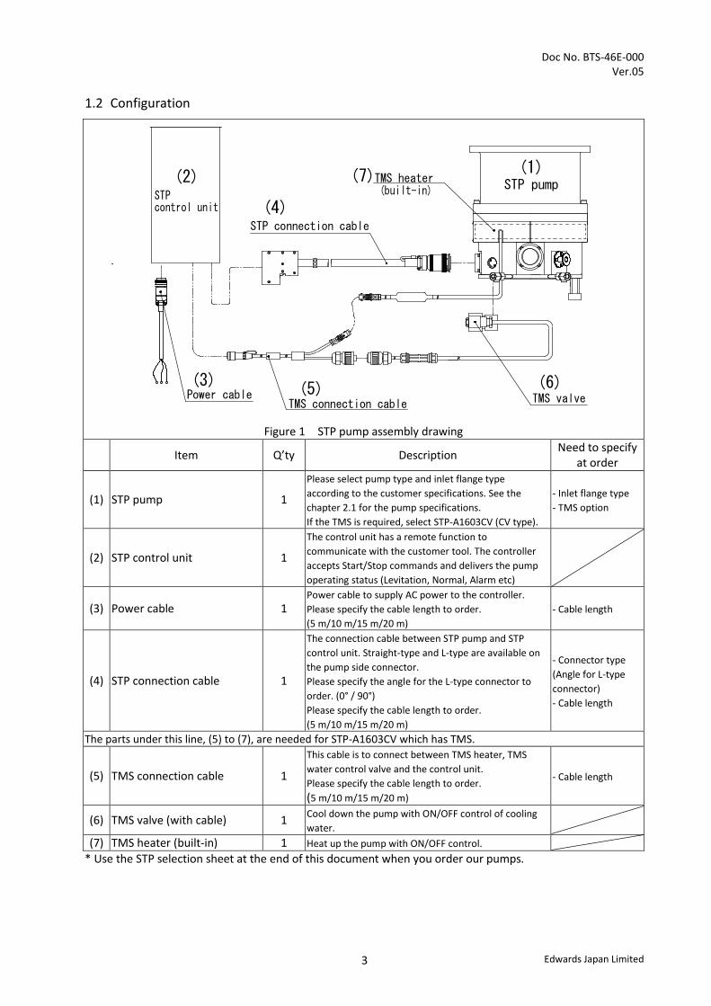
1.2 Configuration
* Use the STP selection sheet at the end of this document when you order our pumps.
TMS heater
STP connection cable
(2)
Power cable(3)
TMS connection cable(5)
TMS valve(6)
(4)
(1)
STPcontrol unit
(7)STP pump(built-in)
Figure 1 STP pump assembly drawing
Item Q’ty Description Need to specify at order
(1) STP pump 1
Please select pump type and inlet flange type according to the customer specifications. See the chapter 2.1 for the pump specifications. If the TMS is required, select STP-A1603CV (CV type).
- Inlet flange type - TMS option
(2) STP control unit 1
The control unit has a remote function to communicate with the customer tool. The controller accepts Start/Stop commands and delivers the pump operating status (Levitation, Normal, Alarm etc)
(3) Power cable 1 Power cable to supply AC power to the controller. Please specify the cable length to order. (5 m/10 m/15 m/20 m)
- Cable length
(4) STP connection cable 1
The connection cable between STP pump and STP control unit. Straight-type and L-type are available on the pump side connector. Please specify the angle for the L-type connector to order. (0° / 90°) Please specify the cable length to order. (5 m/10 m/15 m/20 m)
- Connector type (Angle for L-type connector) - Cable length
The parts under this line, (5) to (7), are needed for STP-A1603CV which has TMS.
(5) TMS connection cable 1
This cable is to connect between TMS heater, TMS water control valve and the control unit. Please specify the cable length to order. (5 m/10 m/15 m/20 m)
- Cable length
(6) TMS valve (with cable) 1 Cool down the pump with ON/OFF control of cooling water.
(7) TMS heater (built-in) 1 Heat up the pump with ON/OFF control.

Doc No. BTS-46E-000 Ver.05
Edwards Japan Limited 4
2 STP Pump
2.1 STP pump specification
Pump Type STP-A1603C STP-A1603CV TMS unit Without TMS With TMS
Flange size
Inlet port flange VG200/ISO200F/ISO250F Outlet port flange KF40 Purge port flange KF10
Pumping speed (L/s) *1 (see chapter 7.1)
N2 1600 H2 1200
Compression ratio *1 N2 >108 H2 7×10³
Allowable maximum continuous flow rate
*1,*2 (sccm) N2 2500 1000
Ultimate pressure *1, *3 Pa 10-7 order (10-9 Torr order) <after baking> Allowable maximum backing pressure *1 Pa 266 (2 Torr)
Enable exhaust gas Chlorine and Fluorine gas can be used. When you want to use the following gas, pleae contact Edwards. The gas including alkali metal, but except “Li”. The gas including “Ga”, “Hg”, “In” and “Sn”. HBr
Purge gas flow rate sccm 20 to 50 (see chapter 2.2.2) Back pump size L/min > 1300
Rated speed Rpm 36,500 (Allowable speed range: 18,000 to 36,500)
Starting time min 7 Stopping time min 9 Baking temperature °C <120 No baking possible with TMS Lubricating oil Not necessary Installation position Free Cooling method Water cooling Water cooling controlled by TMS TMS temperature setting °C - 60
Water Cooling
Flow rate L/min 2 Temperature °C 5 to 25 Pressure MPa < 0.3
Water cooling fitting Size Rc 1/4 (ISO standard)
Material Stainless steel Mass kg 35 Dimension mm See chapter 7.3 Pump Overview Chart Ambient air temp. range °C 0 to 40 Storage temp. range °C -25 to 55 Connection cable length m 30 (maximum) The data inside above table are the typical measured value. It’s not guaranteed performance.
*1 : Pumping speed, compression ratio, allowable maximum continuous flow rate, ultimate pressure and allowable backing
pressure are measured by Edwards method *2 : Allowable maximum continuous flow rate varies depend on the cooling methods. The pumping speed of 1300 (L/min) dry
pump was used for the measurements. *3 : Ultimate pressure is a value after baking.
Doc No. BTS-46E-000 Ver.05
Edwards Japan Limited 5
2.2 Precaution before installing the STP pump
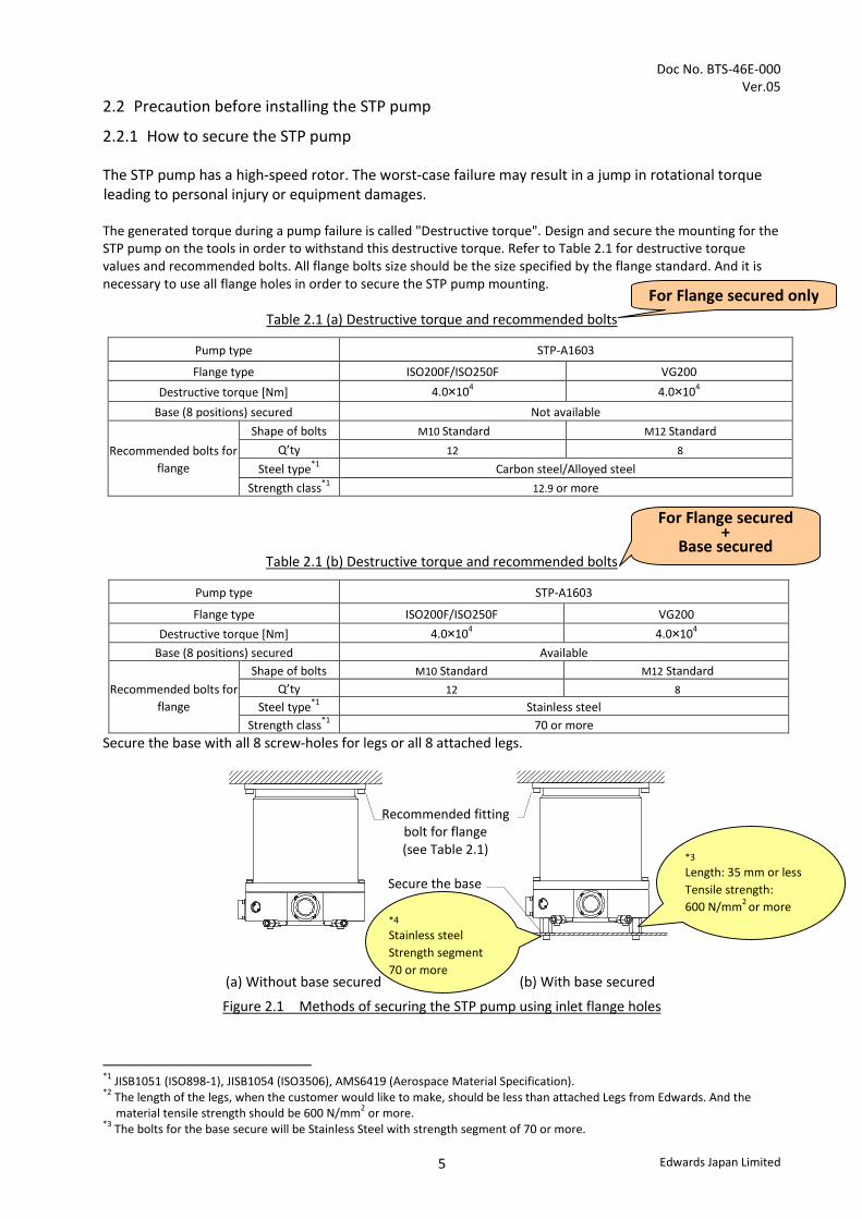
2.2.1 How to secure the STP pump The STP pump has a high-speed rotor. The worst-case failure may result in a jump in rotational torque leading to personal injury or equipment damages. The generated torque during a pump failure is called "Destructive torque". Design and secure the mounting for the STP pump on the tools in order to withstand this destructive torque. Refer to Table 2.1 for destructive torque values and recommended bolts. All flange bolts size should be the size specified by the flange standard. And it is necessary to use all flange holes in order to secure the STP pump mounting.
Table 2.1 (a) Destructive torque and recommended bolts
Pump type STP-A1603
Flange type ISO200F/ISO250F VG200 Destructive torque [Nm] 4.0×10⁴ 4.0×10⁴
Base (8 positions) secured Not available
Recommended bolts for flange
Shape of bolts M10 Standard M12 Standard
Q’ty 12 8
Steel type*1 Carbon steel/Alloyed steel Strength class*1 12.9 or more
Table 2.1 (b) Destructive torque and recommended bolts
Pump type STP-A1603
Flange type ISO200F/ISO250F VG200 Destructive torque [Nm] 4.0×10⁴ 4.0×10⁴
Base (8 positions) secured Available
Recommended bolts for flange
Shape of bolts M10 Standard M12 Standard Q’ty 12 8
Steel type*1 Stainless steel Strength class*1 70 or more
Secure the base with all 8 screw-holes for legs or all 8 attached legs. *3
(a) Without base secured (b) With base secured
Figure 2.1 Methods of securing the STP pump using inlet flange holes
*1 JISB1051 (ISO898-1), JISB1054 (ISO3506), AMS6419 (Aerospace Material Specification). *2 The length of the legs, when the customer would like to make, should be less than attached Legs from Edwards. And the
material tensile strength should be 600 N/mm2 or more. *3 The bolts for the base secure will be Stainless Steel with strength segment of 70 or more.
For Flange secured +
Base secured
For Flange secured only
*3 Length: 35 mm or less Tensile strength: 600 N/mm2 or more
*4
Stainless steel Strength segment 70 or more
Recommended fitting bolt for flange (see Table 2.1)
Secure the base
Doc No. BTS-46E-000 Ver.05
Edwards Japan Limited 6
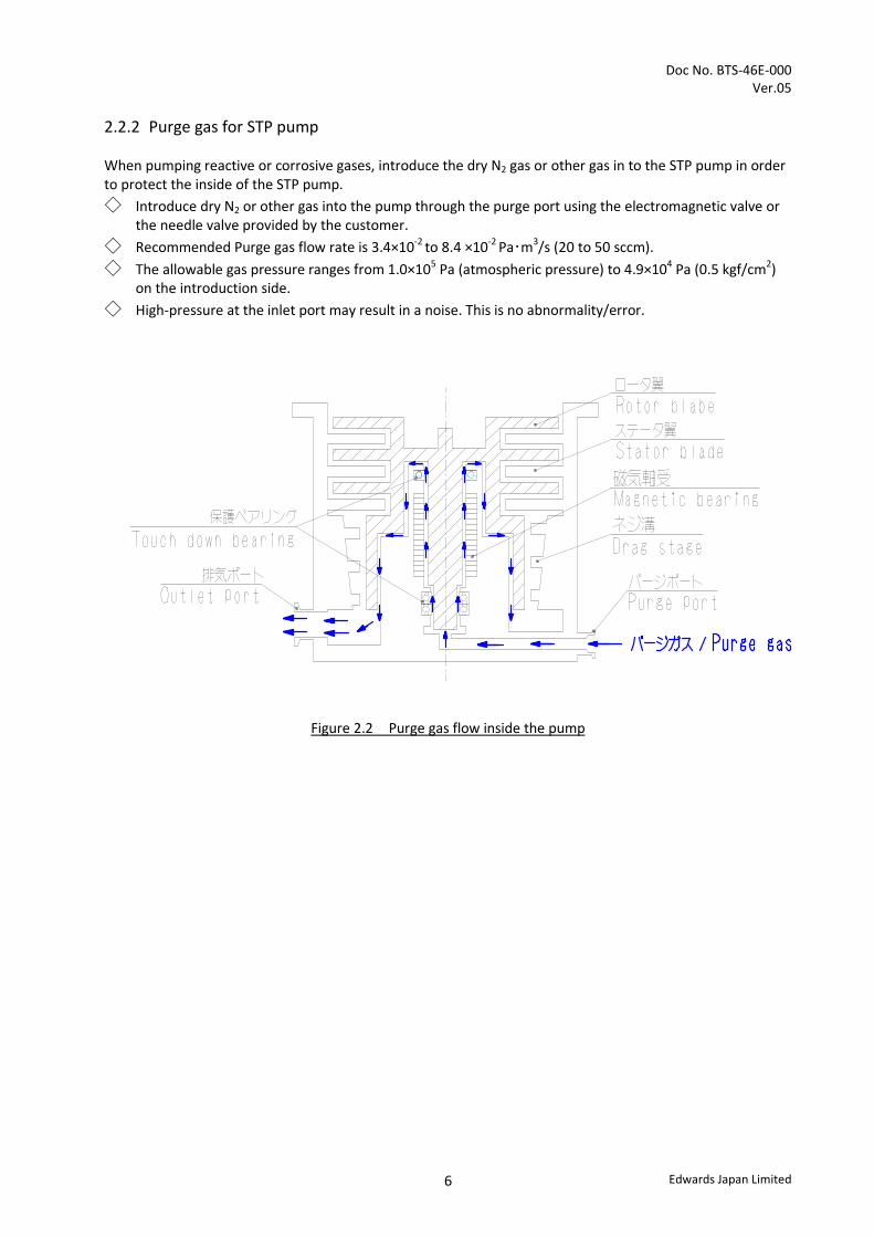
2.2.2 Purge gas for STP pump
When pumping reactive or corrosive gases, introduce the dry N2 gas or other gas in to the STP pump in order to protect the inside of the STP pump. ◇ Introduce dry N2 or other gas into the pump through the purge port using the electromagnetic valve or
the needle valve provided by the customer. ◇ Recommended Purge gas flow rate is 3.4×10⁻² to 8.4 ×10⁻² Pa・m3/s (20 to 50 sccm). ◇ The allowable gas pressure ranges from 1.0×10⁵ Pa (atmospheric pressure) to 4.9×10⁴ Pa (0.5 kgf/cm2)
on the introduction side. ◇ High-pressure at the inlet port may result in a noise. This is no abnormality/error.
Figure 2.2 Purge gas flow inside the pump

Doc No. BTS-46E-000 Ver.05
Edwards Japan Limited 7
3 STP control unit specification
Item Specification Controller type SCU-800
Input voltage Vac 200 to 240 Input frequency Hz 50/60+/-2 Input phase Single phase Input power (Maximum value)
Without TMS VA 850 With TMS VA 1200
Inrush current A 25 0-P Leakage current mA 3.5 or less
Main breaker Rated current A 15 AIC:Ampere Interrupting Capacity
A 1000 (240 Vac: 50/60 Hz)
Allowable operating temperature °C 0 to 40 Allowable storage temperature °C -25 to 55 Mass kg 9 Remote interface I/O Remote (see 8.1)
RS232/RS485 (see 8.2)
External view of STP control unit SCU-800

Doc No. BTS-46E-000 Ver.05
Edwards Japan Limited 8
4 Power cable specification
Control unit side Primary power source side Unit: mm
Lm+5%
ー0%
2mm ×3core2
Specify the length (Lm) in ordering
Crimp TypeTerminal Lug M4
φ10
.1
(91.3)
φ34
.13
4pin(socket type)
(41.3)30
+5 0
black1(L)black2(N)green/yellow(PE)
N.CN
L
Key
PE( )
X2
External view of Power cable (Maximum length is 30 m)
5 STP connection cable specification
Control unit side Pump side Unit: mm
External view of STP connection cable (Maximum length is 30 m)

Doc No. BTS-46E-000 Ver.05
Edwards Japan Limited 9
6 TMS unit specification
6.1 TMS connection cable
Control unit side Pump side Unit: mm
65.3
17
1821.7
98
φ31
L m
100
200 57
φ30
φ10
External view of TMS connection cable (Maximum length is 30m)
6.2 TMS valve (with cable)
Unit: mm
66.523.5
11
8
2
50
62
27.5
2-φ6
2-Rc1/4
Valve:AB41-02-3-D2EB-AC220V (CKD)
Cable(Cable length:1.5m)
Connector(male)
80.5
30 18
36
External view of TMS valve (with cable)

Doc No. BTS-46E-000 Ver.05
Edwards Japan Limited 10
7 STP pump detailed specification
7.1 Pumping speed graph
Graph 1
7.2 Throughput graph (P-Q curve)
Graph 2
Doc No. BTS-46E-000 Ver.05
Edwards Japan Limited 11
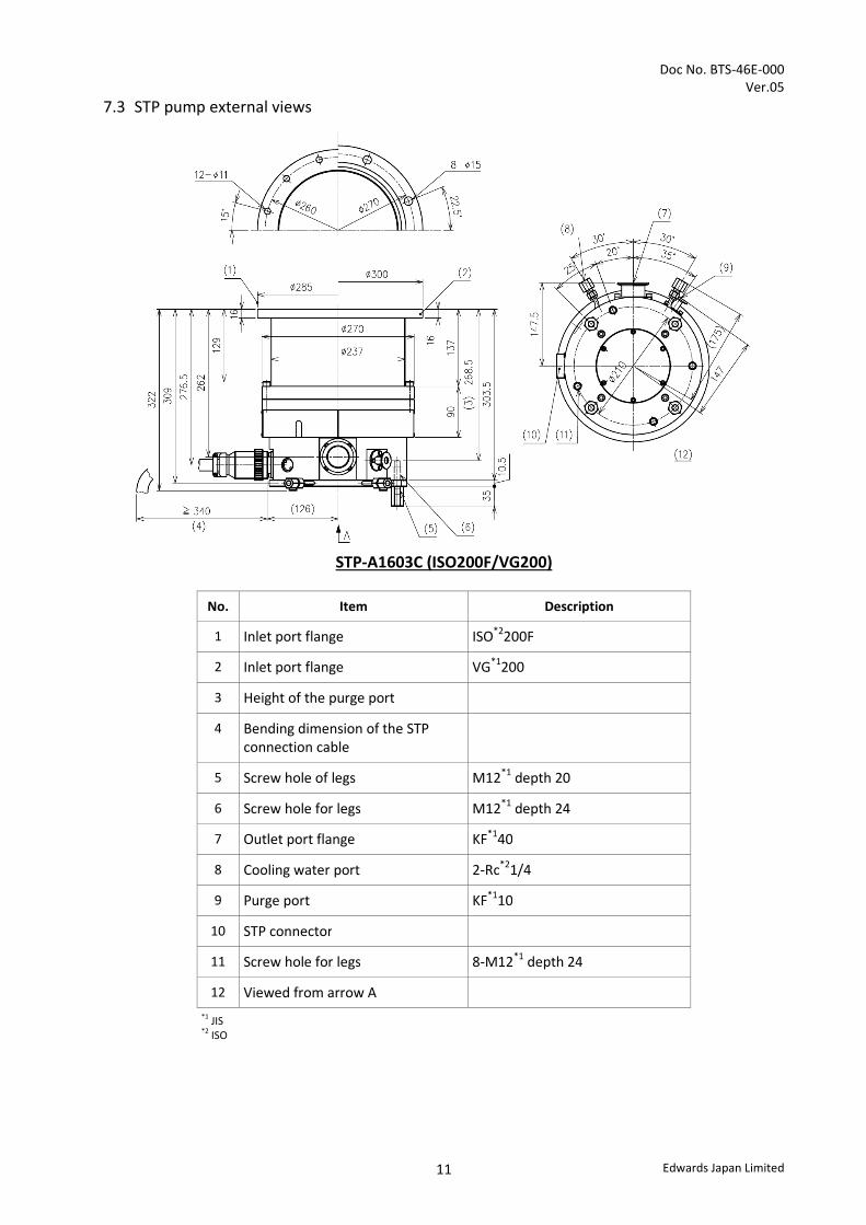
7.3 STP pump external views
STP-A1603C (ISO200F/VG200)
No. Item Description
1 Inlet port flange ISO*2200F
2 Inlet port flange VG*1200
3 Height of the purge port
4 Bending dimension of the STP connection cable
5 Screw hole of legs M12*1 depth 20
6 Screw hole for legs M12*1 depth 24
7 Outlet port flange KF*140
8 Cooling water port 2-Rc*21/4
9 Purge port KF*110
10 STP connector
11 Screw hole for legs 8-M12*1 depth 24
12 Viewed from arrow A *1 JIS *2 ISO
Doc No. BTS-46E-000 Ver.05
Edwards Japan Limited 12
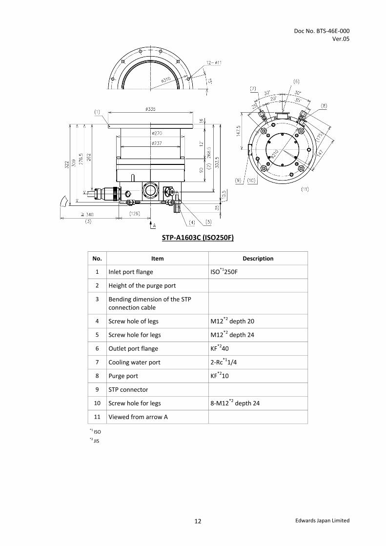
STP-A1603C (ISO250F)
No. Item Description
1 Inlet port flange ISO*1250F
2 Height of the purge port
3 Bending dimension of the STP connection cable
4 Screw hole of legs M12*2 depth 20
5 Screw hole for legs M12*2 depth 24
6 Outlet port flange KF*240
7 Cooling water port 2-Rc*11/4
8 Purge port KF*210
9 STP connector
10 Screw hole for legs 8-M12*2 depth 24
11 Viewed from arrow A
*1 ISO *2 JIS
Doc No. BTS-46E-000 Ver.05
Edwards Japan Limited 13
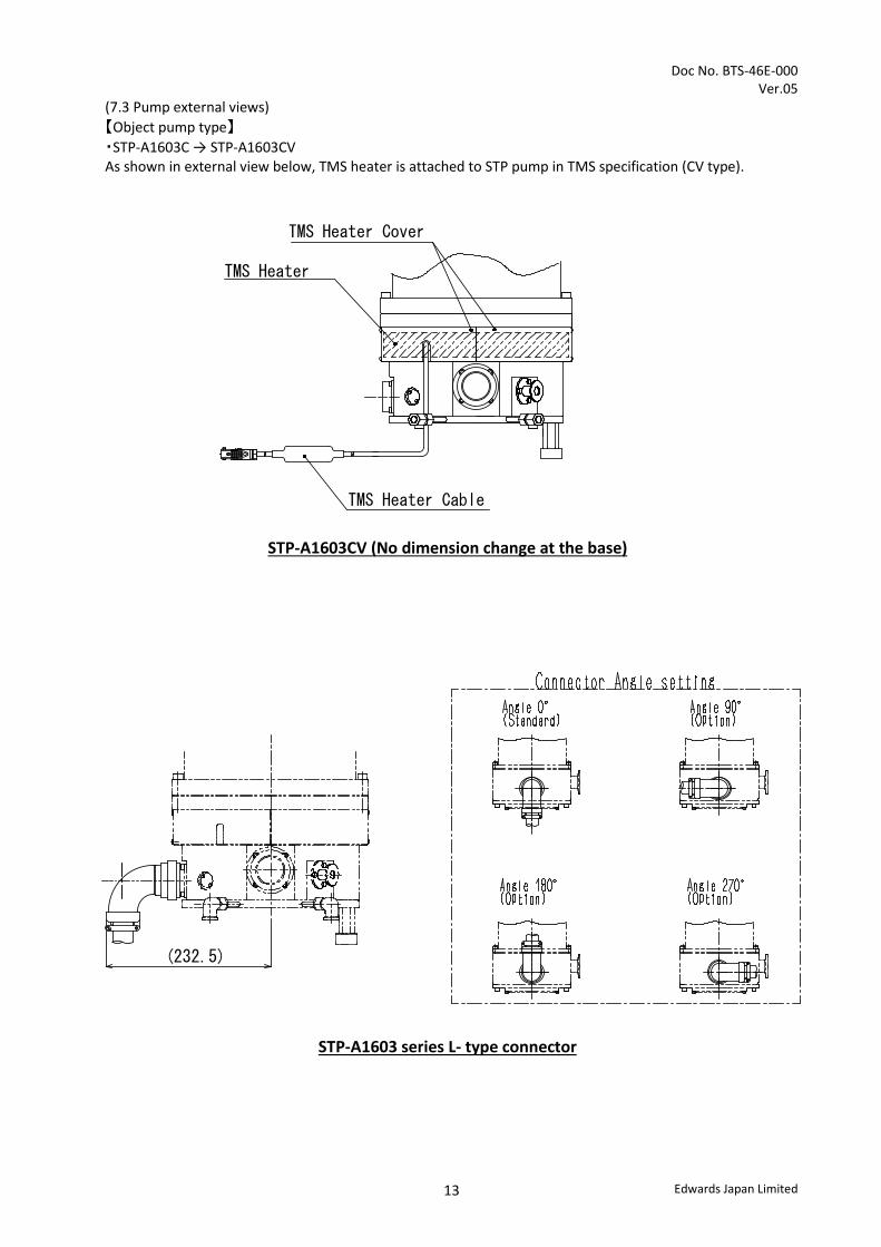
(7.3 Pump external views) 【Object pump type】 ・STP-A1603C → STP-A1603CV As shown in external view below, TMS heater is attached to STP pump in TMS specification (CV type).
TMS Heater
TMS Heater Cable
TMS Heater Cover
STP-A1603CV (No dimension change at the base)
(232.5)
STP-A1603 series L- type connector

Doc No. BTS-46E-000 Ver.05
Edwards Japan Limited 14
8 STP control unit detailed specification
8.1 I/O Remote
Specification for Remote input and output signal on Remote Connector X7 *1 Pin No. Description Pin No. Description
1 COM. (IN) 20 2 21 STOP IN 3 START IN 22 RESET IN 4 REM_IN_OPT1 *2 23 REM_IN_OPT2 *2 5 INHIBIT IN 24 WARNING OUT (N.O.) 6 WARNING OUT (COM) 25 WARNING OUT (N.C.) 7 L.VALVE OUT (N.O.) *2 26 L.VALVE OUT (N.O.) *2 8 REMOTE OUT (N.O.) 27 REMOTE OUT (N.O.) 9 POWER OUT (N.O.) 28 POWER OUT (N.O.)
10 ACCELERATION OUT (N.O.) 29 ACCELERATION OUT (N.O.) 11 NORMAL OUT (N.O.) 30 NORMAL OUT (COM.) 12 NORMAL OUT (N.C.) 31 13 BRAKE OUT (N.O.) 32 BRAKE OUT (N.O.) 14 ALARM OUT (N.O.) 33 ALARM OUT (COM.) 15 ALARM OUT (N.C.) 34 16 AT TEMP. OUT (N.O.) *3 35 AT TEMP. OUT (N.C.) *3 17 AT TEMP. OUT (COM.) *3 36 OPT.1 OUT (N.O.) *2 18 OPT.1 OUT (COM) *2 37 OPT.1 OUT (N.C.) *2 19
IN: Input pin, OUT: Output pin. COM.: Common, N.O.*4 : Normal Open, N.C.*5 : Normal Close, Input signal specification: Operation by Close/Open between COM. (IN) and each Input pin. Output signal specification: Relay contact output. Contact point ratings is 125Vac/0.5A, 24Vdc/1A Connector type: D-sub 37 pin (Socket), The screw for the remote connector is M2.6.
Connector for the remote cable needs to be provided by the customer. It is recommended to use a remote cable with shield type, and connect both terminals to ground.
*1 : Please refer to the Instruction Manual for the detail explanations. *2 : This is not used in the standard specification pump. *3 : This signal will be set when TMS detects the measured temperature is inside +/- 10 °C from the setting temperature. *4 : N.O; The contact will close when the STP pump status becomes the stated status. *5 : N.C; The contact will open when the STP pump status becomes the stated status.

Doc No. BTS-46E-000 Ver.05
Edwards Japan Limited 15
8.2 RS232/RS485
Specification of Serial port COM1 (X3A, X3B) for both RS232 and 485 *1
STP control unit side X3A
STP control unit side X3B
PC side connector (example of DOS/V compatible machine)
(D-sub 9 pin, Socket) (D-sub 9 pin, Socket) D-sub 9 pin D-sub 25 pin RS232 2 (TxD) - 2 (TxD) 3 (TxD)
3 (RxD) - 3 (RxD) 2 (RxD) 5 (GND) - 5 (GND) 7 (GND)
RS485 7 (D-) 7 (D-) - - 8 (D+) 8 (D+) - -
Not for use 1, 4, 6, 9 1, 2, 3, 4, 5, 6, 9 - - Screw size of the connector housing for X3A and X3B is M2.6. The connectors for the serial cables need to be provided by the customer. It is recommended to use a serial communication cable with shield type, and connect both terminals to ground. DO NOT connect anything to these unused pins.
9 Attachment component Below parts are attached with the pump as standard.
Item Q’ ty Note Blank Flange for Parge port (KF10) 1 Clamper for purge port (KF10) 1 O-ring for the purge port (KF10) 1 Leg 8 Instruction Manual 1 10 Accessory There is no accessory available for STP-A1603 series.
Attached to Doc No. BTS-46E-000 Ver.05
Turbo Molecular Pump STP-A1603 series Selection Guide
Edwards Japan Limited
Pump Type - STP-A1603C - STP-A1603CV

Attached to Doc No. BTS-46E-000 Ver.05
Edwards Japan Limited
STP-A1603 series Selection Guide
Please complete a kit using the Product Structure and the Selection Flow Chart. <Product Structure>
< Selection Flow Chart >
Select pumping speed or the flange size
1600L/s VG200/ISO200F/ISO250F
Is any by-products deposition expected?
Type:STP-A1603C
Yes
No
Type:STP-A1603CV
Please check the Selection Guide Sheet of STP-A1603C
Please check the Selection Guide Sheet of STP-A1603CV
TMS unit is needed
No TMS unit is needed
Item Q’ty (1) STP pump 1 (2) STP control unit 1 (3) Power cable 1 (4) STP connection cable 1
Parts (5) to (7) under this line are for STP-A1603CV (with TMS) only (5) TMS connection cable 1 (6) TMS valve (with cable) 1 (7) TMS heater (built in the pump) 1
TMS heater
STP connection cable
(2)
Power cable(3)
TMS connection cable(5)
TMS valve(6)
(4)
(1)
STPcontrol unit
(7)STP pump(built-in)
Attached to Doc No. BTS-46E-000 Ver.05
Edwards Japan Limited
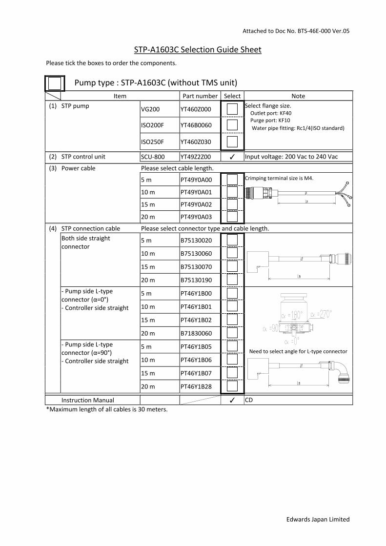
STP-A1603C Selection Guide Sheet Please tick the boxes to order the components.
Pump type : STP-A1603C (without TMS unit)
Item Part number Select Note (1) STP pump VG200 YT460Z000
Select flange size. Outlet port: KF40 Purge port: KF10 Water pipe fitting: Rc1/4(ISO standard)
ISO200F YT46B0060
ISO250F YT460Z030
(2) STP control unit SCU-800 YT49Z2Z00 ✓ Input voltage: 200 Vac to 240 Vac
(3) Power cable Please select cable length. 5 m PT49Y0A00 Crimping terminal size is M4.
10 m PT49Y0A01
15 m PT49Y0A02
20 m PT49Y0A03
(4) STP connection cable Please select connector type and cable length. Both side straight
connector 5 m B75130020
10 m B75130060 15 m B75130070 20 m B75130190 - Pump side L-type
connector (α=0°) - Controller side straight
5 m PT46Y1B00
Need to select angle for L-type connector
10 m PT46Y1B01 15 m PT46Y1B02 20 m B71830060 - Pump side L-type
connector (α=90°) - Controller side straight
5 m PT46Y1B05 10 m PT46Y1B06 15 m PT46Y1B07 20 m PT46Y1B28
B75130020 Instruction Manual ✓ CD *Maximum length of all cables is 30 meters.

Attached to Doc No. BTS-46E-000 Ver.05
Edwards Japan Limited
STP-A1603CV Selection Guide Sheet Please tick the boxes to order the components.
Pump type : STP-A1603CV (without TMS unit)
Item Part number Select Note (1) STP pump VG200 YT4616003
Select flange size. Outlet port: KF40 Purge port: KF10 Water pipe fitting: Rc1/4(ISO standard)
With TMS heater (7) ISO200F YT4616004
ISO250F YT4616030
(2) STP control unit SCU-800 YT49Z2Z00 ✓ Input voltage: 200Vac to 240Vac
(3) Power cable Please select cable length. 5 m PT49Y0A00 Crimping terminal size is M4.
10 m PT49Y0A01
15 m PT49Y0A02
20 m PT49Y0A03
(4) STP connection cable Please select connector type and cable length. Both side straight
connector 5 m B75130020
10 m B75130060 15 m B75130070 20 m B75130190 - Pump side L-type
connector (α=0°) - Controller side straight
5 m PT46Y1B00
Need to select angle for L-type connector
10 m PT46Y1B01 15 m PT46Y1B02 20 m B71830060 - Pump side L-type
connector (α=90°) - Controller side straight
5 m PT46Y1B05 10 m PT46Y1B06 15 m PT46Y1B07 20 m PT46Y1B28
(5) TMS connection cable Kit Please select cable length. Include TMS connection
cable and TMS valve (6). TMS heater (7) is included in the Pump.
5 m PT461V000 L m 10 m PT461V001
15 m PT461V002
20 m PT461V003
Instruction Manual ✓ CD *Maximum length of all cables is 30 meters.


![Turbo Molecular Pump [UTM Series] - หน้าแรก...Turbo Molecular Pump [UTM Series] The UTM series is an all the blades type turbo molecular pump which carries a pivot bearing](https://static.fdocuments.in/doc/165x107/613fcae8b44ffa75b8047402/turbo-molecular-pump-utm-series-aaaaaaa-turbo-molecular-pump.jpg)