LEAK DETECTORS - Turbo Pump Repair, Turbomolecular Pump Repair
36
EDITION 2007 CATALOG LEAK DETECTORS
Transcript of LEAK DETECTORS - Turbo Pump Repair, Turbomolecular Pump Repair

EDITION 2007
CATALOGLEAK DETECTORS
INF_CatalogB5_0705 16.05.2007 14:59 Uhr Seite 1

ContentsLeak Detectors
Leak Detectors Catalog 2007.2
General
Applications and Accessories. . . . . . . . . . . . . . . . . . . . . . . . . . . . . . . . . . . . . . . . 03
Leak Detection - Leak Testing . . . . . . . . . . . . . . . . . . . . . . . . . . . . . . . . . . . . . . . 04
Leak Detection Methods . . . . . . . . . . . . . . . . . . . . . . . . . . . . . . . . . . . . . . . . . . . . 05
Operating Principles of the INFICON Helium Leak Detectors . . . . . . . . . . . . . . . 07
Products
Modular System Leak Detectors for universal integration into industrial leak testing systems
LDS2010 . . . . . . . . . . . . . . . . . . . . . . . . . . . . . . . . . . . . . . . . . . . . . . . . . . . . . . . 10
Modular Helium Leak Detectors for integration into medium automated test benches
Modul1000 . . . . . . . . . . . . . . . . . . . . . . . . . . . . . . . . . . . . . . . . . . . . . . . . . . . . . 12
Helium Leak Detectors (vacuum)
UL1000 . . . . . . . . . . . . . . . . . . . . . . . . . . . . . . . . . . . . . . . . . . . . . . . . . . . . . . . . 14
UL1000 Fab . . . . . . . . . . . . . . . . . . . . . . . . . . . . . . . . . . . . . . . . . . . . . . . . . . . . 16
UL5000 . . . . . . . . . . . . . . . . . . . . . . . . . . . . . . . . . . . . . . . . . . . . . . . . . . . . . . . 18
Helium Sniffer Leak Detectors
Protec P3000 . . . . . . . . . . . . . . . . . . . . . . . . . . . . . . . . . . . . . . . . . . . . . . . . . . . 20
Refrigerant Sniffer Leak Detectors
Ecotec E3000 for Refrigerants and other gases. . . . . . . . . . . . . . . . . . . . . . . . . 22
Ecotec E3000A Multi-gas Leak Detector for Airbus airplanes . . . . . . . . . . . . . . 24
HLD5000 Refrigerant Sniffer Leak Detector . . . . . . . . . . . . . . . . . . . . . . . . . . . . 26
Accessories
Calibrated Test Leaks . . . . . . . . . . . . . . . . . . . . . . . . . . . . . . . . . . . . . . . . . . . . . . 28
Calibrated Leaks for System Applications. . . . . . . . . . . . . . . . . . . . . . . . . . . . . . . 30
Sample Probes (Sniffers) and Accessories. . . . . . . . . . . . . . . . . . . . . . . . . . . . . . 32
Connection Flanges and Components . . . . . . . . . . . . . . . . . . . . . . . . . . . . . . . . . 34
INF_CatalogB5_0705 16.05.2007 14:59 Uhr Seite 2
Leak Detectors
Leak Detectors Catalog 2007.3
B5B5
General
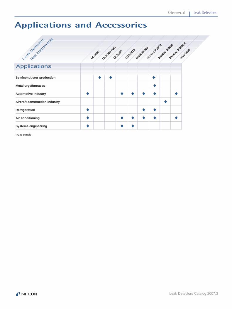
Semiconductor production
Metallurgy/furnaces
Automotive industry
Aircraft construction industry
Refrigeration
Air conditioning
Systems engineering
*) Gas panels
Applications
UL1000
UL1000
Fab
UL5000
Ecote
c E30
00
Prote
c P30
00
◆ ◆ ◆ *)
◆
◆ ◆ ◆ ◆ ◆ ◆
◆
◆ ◆ ◆
◆ ◆ ◆ ◆ ◆ ◆
◆ ◆ ◆
HLD5000
Applications and Accessories
Test In
stru
men
ts
Leak
Det
ecto
rs
LDS2010
Ecote
c E30
00A
Modul1000
INF_CatalogB5_0705 16.05.2007 14:59 Uhr Seite 3

Leak Detectors
Leak Detectors Catalog 2007.4
General
Whether a component or a system is leak-tight depends onthe application and its acceptable leak rate. Absolutely leak-tight components and systems do not exist. A component isconsidered leak-tight if its leak rate remains below a valuedefined for that particular component. In order to provide aquantitative measure, the term “leak rate” with the symbol “qL”was introduced.In vacuum technology, mbar l/s is used as the unit for leakrates.
A leak rate of 1 mbar l/s exists in a closed vessel having avolume of 1 liter when the pressure increases by 1 mbar with-in one second, or in case of an overpressure it decreases by1 mbar within one second.
qL = V · ∆p (mbar l/s)∆t
The wide range of leak rates from several 100 mbar l/s to below 10-11 mbar l/s as they occur in practice necessitatesthe use of different leak detection principles and hence leakdetectors (see figure 1).
Besides the determination of the total leak tightness, it is usually important to locate the leak, quickly and precisely, inorder to seal it. Instruments for local leak detection are calledleak detectors. The leak detectors presented in this catalogcan be used for the localization of leaks, and in addition someare suitable for determining the total leak rate of test objects.
Leak Detection – Leak Testing
Pressure drop test
Bubble test
Overp
ressu
re m
eth
od
Vacu
um
meth
od
Helium sniffer Protec P3000
Refrigerant sniffer HLD5000
Multi-gas sniffer Ecotec E3000
Helium sniffer Protec P3000
Refrigerant sniffer HLD5000
Multi-gas sniffer Ecotec E3000
Helium leak detector UL1000 / UL1000 FAB / UL5000
Helium leak detector LDS2010 / Modul1000
Pressure rise method
Fig.1: Overview of the leak rate detection ranges
atm cm3/s* kg/h-1 g/ambar l/s * cm3 x s-1 * torr l/s* Pa m3/s air C2H2F4 (R134a)
1 mbar l/s (He) 1 0.99 0.75 0.1 4.3 x 10⁻³ 2.28 x 10⁵
1 atm cm3/s = cm3 (STP) s-1 * 1.01 1 0.76 0.101 4.3 x 10⁻³ 2.3x 10⁵
1 torr l/s* 1.33 1.33 1 0.133 5.7 x 10⁻³ 3.0 x 10⁵
Pa m3/s 10 9.87 7.5 1 4.28 x 10⁻² 2.28 x 10⁶
1 kg/h-1 air 234 234 175 23.4 1 –
1 g/a C2H2F4 (R134a) 7.58 x 10⁻⁶ 6.3 x 10⁻⁶ 4.8 x 10⁻⁶ 6.41 x 10⁻⁷ – 1
* According to international system of units only Pa m3/s is permissible
SPECIFICATIONS
Fig.2:
INF_CatalogB5_0705 16.05.2007 14:59 Uhr Seite 4

Leak Detectors
Leak Detectors Catalog 2007.5
B5
General
There are two main groups of leak detection methods:Vacuum and overpressure. Many variations exist dependingon the particular application.
Vacuum Methods
The equipment to be tested is evacuated. The pressure ratiobetween inside and outside is 0:1.
Overpressure Methods
The equipment to be tested is pressurized with a search gasor a search gas mixture. The pressure ratio between insideand outside is over 1:1.
General Notes
1. The lowest leak rates can only be measured by employingthe vacuum method, whereby the following applies: The lowerthe leak rate, the higher the requirements are concerningcleanness and ultimate vacuum.
2. If possible the test objects should be tested under the sameconditions that will be used in their final application. That isparts for vacuum operation should be tested according to the vacuum method and parts for overpressure operation shouldbe tested using the overpressure method.
Leak Testing Based on VacuumMethods
Pressure Rise Method
With this method it is only possible to determine the total leakrate. The test object is evacuated with a vacuum pump or avacuum pump system. A valve is used to isolate the testobject from the vacuum pump. The pressure will then riseas a function of time (see fig. 3).
Curve (a) shows the theoretical pressure rise if there is only aleak. Curve (b) shows the pressure rise due to outgassingfrom the surfaces of the test object. This pressure rise tendsto tail off in the direction of a saturation level. If in such a casethe time allowed for monitoring the pressure rise is too short,a leak will be indicated which in reality does not exist. If onewaits long enough for the pressure to rise, i.e. after the bendof curve (b), the outgassing process can then be disregarded.The leak rate can be determined from the known volume ofthe test object and the measured pressure rise over a fixedrise time (see equation on page 4). Curve (c) shows the pressure rise as it occurs in practice, where outgassing andleak rate combine. The detectable leak rate depends on the volume of the test object, the obtained ultimate pressure andthe outgassing from the test object. In connection with verylarge test objects this method is time consuming if extremelylow leak rates are to be determined in the fine and rough vacuum range.
Local Leak Detection
The test object is evacuated by a vacuum pump (auxiliarypump) until the pressure is low enough for the leak detector tooperate (refer to fig.4). When using a helium leak detector, itsown pump system will take care of further evacuation.Suspicious spots on the test object will then be sprayed with afine jet of search gas. Search gas entering through leaks intothe test object is pumped out by the vacuum pump and isconverted by the leak detector into an electrical signal whichis then displayed. This permits rapid detection and determina-tion of the size of even the smallest leaks.
Leak Detection Methods
1
2
3
4
5
LD
HELIUM
Key to Figure1 Test object, 2 Leak detector, 3 Search gas cylinder, 4 Vacuum pump,5 Spray gun for search gas
Fig. 4: Local leak detection – Evacuated test object
a) Pressure rise due to leakageb) Pressure rise due to outgassing from the chamber wallsc) Both effects combined
Fig. 3: Pressure rise in a vacuum chamber after switching off the pump; double log. plot
INF_CatalogB5_0705 16.05.2007 14:59 Uhr Seite 5

Leak Detectors
Leak Detectors Catalog 2007.6
Local Leak Detection with LeakDetectors – Sniffing
The test object is filled with the search gas or the searchgas/air mixture to which the leak detector is sensitive. Theleak detector is equipped with a sniffer probe, with low pressure at the probe tip. As the sniffer tip passes suspiciouspoints on the test object, the search gas coming out of theleak is sucked in and transferred to the detection system ofthe leak detector. After conversion into electrical signals theleaks are displayed optically and acoustically by the leakdetector.
Integral Method – Hood Test 0
To determine the total leak rate of a test object subjected to asearch gas overpressure, the test object is surrounded by ahood of a known volume (refer to fig. 7). The search gaswhich escapes through the leaks collects in the hood.After a fixed accumulation period a sniffer probe is used tomeasure the concentration of the search gas which has collected in the hood. The leak detector should be previouscalibrated by a reference measurement using a known searchgas concentration. The leak rate can then be determined bythe equation for qL where V is the volume of the hood, ∆p is the partial pressure difference of the search gas (concentration change) and t is the accumulation period.Uncertainties in the determination of the volume, leaks in thehood and a wrong accumulation period make precise leakrate measurements based on this method very questionable.
Integral Method – Vacuum Hood Test
This test is a variation of the hood test described above, providing considerable advantages (refer to fig. 8). A vacuumchamber which is evacuated by an auxiliary pump and whichis connected to a leak detector is used as the hood.The search gas escaping through the leaks is converted bythe leak detector into electrical signals which are immediately displayed. After calibration of the leak detector with a calibrated leak, it is possible to quantitatively determine thetotal leak rate. This method permits the detection of very smallleaks and is especially suited for automatic industrial leakdetection.
General
Integral Method
Determination of the total leak rateof a test object
The testing arrangement is the same as for local leak detection, but in this case the test object is not sprayed withsearch gas on selected areas, but it is surrounded by a hoodor a chamber which is filled with the search gas (refer to fig. 5). Thus the entire outer surface of the test object comesinto contact with the search gas. If the search gas enters thetest object, the total leak rate is indicated independently of the number of existing leaks. With helium leak detectors it ispossible to determine the helium content of the air. This is utilized in the detection of gross leaks.
Leak Testing Based on Overpressure Methods
Pressure Drop Method
The test object is filled with a gas (for example air or nitrogen)until the testing pressure is reached (refer to fig. 6). Precisionvacuum gauges are used to detect a possible pressure dropduring the testing period. This method is simple to implement,it is suitable for the determination of gross leaks and can beimproved upon by using differential pressure gauges. Byapplying soap solutions or similar, leaks can be located.
2
3
4
LD
HELIUM
1
5
Fig. 5: Integral method – Evacuated test object
Key to Figure1 Test object, 2 Leak detector, 3 Search gas cylinder, 4 Vacuum pump, 5 Hood
2
3
LD
HELIUM
1
7
Fig. 6: Leak detection – Search gas overpressure in the test object
2
3
LD
HELIUM
1
7
5
Fig. 7: Integral method (search gas accumulation)Search gas overpressure in the test object
Key to Figure1 Test object, 2 Leak detector, 3 Search gas cylinder, 5 Hood, 7 Sniffer probe
Key to Figure1 Test object, 2 Leak detector, 3 Search gas cylinder, 7 Sniffer probe
INF_CatalogB5_0705 16.05.2007 14:59 Uhr Seite 6

Leak Detectors
Leak Detectors Catalog 2007.7
B5
General
Integral Method – Bombing-Test
This method is used for testing hermetically sealed compo-nents such as transistors, IC-packages or dry reed relays.
It is basically a variation of the vacuum hood test. Here thetest objects are placed in a vessel which is pressurized withthe search gas - preferably helium. At a fairly high search gaspressure after a period of up to several hours, search gas isforced inside leaky test objects. This is the actual so called“bombing” process.
After this, the test objects are transferred to a vacuum chamber and their total leak rate is determined in the sameway as in the vacuum hood test. During evacuation of thevacuum chamber down to the required testing pressure, those test objects which have a gross leak may already losttheir accumulated search gas. These parts are not detectedas leaking during the actual leak test. Therefore the test withthe vacuum chamber is often preceded by a “bubble test”.
This method permits the detection of the lowest leak ratesand is used mainly in automatic industrial leak testing especially when it is not possible to fill the parts with gasin any other way.
2
3
4
LD
HELIUM
1
5
Fig. 8: Integral method – Search gas overpressure in the test object
Operating Principles of the Helium LeakDetectors from INFICONOperating Principle
A helium leak detector permits the localization of leaks andthe quantitative determination of the leak rate, i.e. the gas flowthrough the leak. Such a leak detector is a helium flow meter.
The leak detector performs this task by firstly evacuating thepart to be tested, so that gas from the outside may enterthrough a leak due to the pressure difference present.If only helium is brought in front of the leak (for example, byusing a spray gun) this helium flows through the leak and ispumped out by the leak detector. The helium partial pressurepresent in the leak detector is measured by a sector massspectrometer and is displayed as a leak rate. This is usuallygiven in terms of volume flow of the helium (pV-flow).
Important Specifications
The two most important features of a leak detector are its measurement range (detection limits) and its response time.
The measurement range is limited by the lowest and the highest detectable leak rate. The lowest detectable leak rate is defined by the sum of drift and noise in the most sensitivemeasurement range. Usually the sum of noise amplitude andzero drift per minute is equivalent to the lowest detectableleak rate. With INFICON leak detectors the amount of drift is so low, that the noise amplitude alone determines thedetection limit.
The highest detectable leak rate depends strongly on themethod employed. Especially the counterflow method andpartial flow operation (see description below) permit the measurement of very high leak rates even with a sensitivehelium leak detector.
The multi-stage switchable high impedance input amplifiers ofthe INFICON leak detectors also permit the measurement ofhigh leak rates.
In practical applications, especially in the localization of leaksthe response time is of great significance. This is the time ittakes from spraying the test object with helium until a measured value is displayed by the leak detector.The response time of the electronic signal conditioning circuitry is an important factor in the overall response time.In INFICON leak detectors the response time of the electroniccircuitry is well below 1 s.
The volume flow rate for helium at the point of the test objectis of decisive significance to leak detection on componentswhich are pumped down solely by the leak detector.The volume flow rate provided by the leak detector takes careof the helium entering through a leak and it ensures quickdetection by the leak detector.The volume of the test object delays the arrival of the heliumsignal. The response time can be calculated on the basis ofthe following simple equation:
VResponse time for helium tA = 3 · _______SHe
(for 95% of the final value)
with V = Volume of the test objectSHe = Volume flow rate for helium at the point of the test
object (or at the inlet of the leak detector, if it alone pumps down the test object).
Key to Figure1 Test object, 2 Leak detector, 3 Search gas cylinder, 4 Vacuum pump, 5 Hood
INF_CatalogB5_0705 16.05.2007 14:59 Uhr Seite 7

Leak Detectors
Leak Detectors Catalog 2007.8
General
Main Flow Method
The classic operating principle of helium leak detectors isbased on the main flow method (refer to fig. 9). The entirehelium flow passes through the high vacuum system of theleak detector, where the mass spectrometer measures thepartial pressure of the helium. The use of a liquid nitrogencold trap is essential to remove water vapor or other conden-sible gases in the vacuum system which impair the operation.Moreover, the use of a cold trap permits the low operatingpressures for the mass spectrometer to be reached (below10-4 mbar) despite the directly connected (and possibly conta-minated) test object.
The advantages of the main flow method are:– Highest sensitivity, i.e. low detection limit– Short response time due to a high volume flow rate
at the inlet.
The main flow method is thus especially suitable for stationaryleak detection on components. Leak detection on systemshaving their own pump sets and at higher pressures requiresthe use of an external throttling valve, i.e. a partial flow withsubsequently reduced sensitivity is utilized.
Counterflow Method
With this method shown in figure 10, the test object is notconnected to the high vacuum. Instead it is connected to theforevacuum (between the turbomolecular pump and backingpump), so that the entire gas flow (especially water vapor)does not contribute to the pressure increase in the massspectrometer. A cold trap is no longer required.
The helium that enters the forevacuum can still be detected,as it is able to flow against the pumping direction of the turbo-molecular pump into the mass spectrometer. This is due tothe high particle velocity of the helium. The sensitivity of thiscounterflow arrangement is equal to that of the main flow principle, provided the right combination of volume flow rate of the backing pump and helium compression of the turbo-molecular pump is used.
The advantages of the counterflow method are:– No liquid nitrogen is required– High permissible inlet pressures (i.e. pressure within the
test object)
This makes the counterflow method especially suitable formobile leak detection on systems. For leak detection on largercomponents where a short response time is essential (i.e.high volume flow rate) an additional turbomolecular pumpstage is required at the inlet of the leak detector. All INFICONhelium leak detectors offer this optimized counterflow method.
Partial Flow Method
In order to expand the measurement range in the direction ofhigher leak rates and for operation at higher inlet pressures,helium leak detectors incorporate a partial flow or a grossleak system (refer to fig. 11). This consists of a throttle and a rotary vane pump. At pressures above the normal inlet pressure (main flow: above 10-2 mbar, counterflow: above 10-1 mbar) or in the case of high helium leak rates, the inletvalve is closed and the main flow is allowed to enter the partial flow pump, whereas only a small part enters the leakdetector via the partial flow throttle. The total pressure and thehelium pressure are dropped to values suitable for operationof the leak detector.
Fig. 9: Main flow method
Fig. 10: Counterflow method
Fig. 11: Partial flow method
Main flow orcounterflow leak detector
INF_CatalogB5_0705 16.05.2007 14:59 Uhr Seite 8

Leak Detectors
Leak Detectors Catalog 2007.9
B5
General
To obtain correct leak rate readings in the partial flow mode,the partial flow ratio, i.e. the ratio between the actually measured gas flow and the total gas flow, must be known andstable.
Calibration of Helium LeakDetectors with Calibrated Leaks
In the process of leak detection, a test object which does nothave a leak produces a zero reading on the leak detector.In this any malfunctions are excluded. Calibrated leaks, i.e.artificial leaks which produce a known helium leak rate, areessential for reliable results.
To obtain a quantitatively correct leak rate, the sensitivity ofthe leak detector must also be adjusted.This requires the use of a calibrated leak.
INFICON offers calibrated helium leaks of various designscovering the range between 10-7 to 10-4 mbar x l x s-1 as partof the standard range of products. All leak rates are traceableto the standards of the German Calibration Service controlledby the PTB (Federal Institution of Physics and Technology).If requested, each helium calibrated leak can be supplied witha calibration certificate issued by the German CalibrationService.
The calibration itself is performed by the German CalibrationService for Vacuum which is run by Leybold Vacuum onbehalf of the PTB.
INF_CatalogB5_0705 16.05.2007 14:59 Uhr Seite 9

Leak Detectors
Leak Detectors Catalog 2007.10
LDS2010 Modular Leak Detection SystemLeak Detectors
USER ADVANTAGES
· Very fast signal response time due to a very high heliumpumping speed
· No loss of pumping speed caused by long connectiontubes between the system and the leak detector, as thesmall mass spectrometer module can be placed close tothe vacuum chamber
· The rugged and reliable high compression turbo pump- makes the unit insusceptible for rising helium back-
grounds caused by contaminated roughing pumps- allows the use of cost -effective single stage roughing
pumps.
· Short pumping time due to a high max. inlet pressure (20 mbar)
· Variety of data control and acquisition options via:- RS232- RS485- PLC- Profibus compatible with optional converter- Lin/log chart recorder
· Rugged mass spectrometer system with dual filament ionsource (3 years warranty) ensures high uptime andlow maintenance cost
· Switching over from vacuum leak detection to sniffer leakdetection allows for immediate pin-pointing of the leakduring the same test step
· Calibration via internal calibrated leak; also external ordynamic calibration is possible while pumping down is inprogress (faster start-up)
TYPICAL APPLICATIONS
The flexibility of the LDS2010 makes the instrument ideal forthe integration into complex helium leak detection systems.- Evaporators- Condensers- Valves- Compressors- Airbags- Brake lines- Fuel lines- Hydraulic components- Engines
Modular Leak Detector LDS2010 for System Integration in Industrial Leak Testing SystemsThe LDS2010 is a modular helium leak detectors for universalintegration into industrial leak testing systems. This leakdetector was especially designed to speed up industrial leaktest processes.To guarantee a maximum of flexibility in system design thesmall mass spectrometer and the electronics unit are separatemodules. Due to its compact shape the mass spectrometermodule can be placed directly at the test chamber of the system. The electronics module that is prepared for a 19” rackcan be integrated into the control enclosure of the leak testingsystem up to ten meters away from the mass spectrometermodule.
System schematics LDS2010
243 [9 9 /16"]
355,7 [1" - 2"]
CAL. LEAK ULTRA
CAL. LEAK FINE
GAUGE
Dimensional drawing of the mass spectrometer module in mm (inch).
INF_CatalogB5_0705 16.05.2007 14:59 Uhr Seite 10

Leak Detectors
Leak Detectors Catalog 2007.11
B5B5
Leak DetectorsLDS2010 Modular Leak Detection System
B5
Smallest detectable leak rate:ULTRA mode ≤ 2 · 10-11 mbar l/s (5 l/s Helium pumping speed)FINE mode ≤ 2 · 10-10 mbar l/s (1.7 l/s Helium pumping speed)GROSS mode ≤ 8 · 10-8 mbar l/sSNIFFER mode ≤ 5 · 10-8 mbar l/s
Units of measurement (selectable) mbar l/s, Pa m3/s, atm cc/s, g/a, ppm
Max. inlet pressure 20 mbar (FINE 3 mbar, ULTRA 0.4 mbar)
Response time < 1 s
Ion source 2 yttrium/iridium longlife cathodes
Vacuum connections DN 16 KF / DN 25 KF
Relays 4
Control inputs SPS compatible (max. 35 V)
Chart recorder output lin/log 0 - 10 V PLC
Interface RS232, RS485, and Fieldbus options
Dimensions (L x W x H)Mass spectrometer module 348 x 244 x 267 mm (13.7 x 9.6 x 10.5 in.)Electronics module 482.6 x 359.9 x 134.1 mm (19 x 14.17 x 5.28 in.)
LDS2010 consisting of electronic module with integrated operating unit and mass spectrometer 560-100
LDS2010 consisting of electronic module with integrated operating unit and mass spectrometer and 10 m cable 560-101
Connection cable:Electronic module / mass spectrometer module
1.5 m (4.8 ft.) 560-1113 m (10 ft.) 560-1125 m (16 ft.) 560-11310 m (32 ft.) incl. MSV board 560-114
Options:
Pump module (complete with connection accessories)TRIVAC D 4 B, single-phase motor, 230 V, 50/60 Hz 145 11
Sniffer valve 145 20
Sniffer line, incl. handle with sniffer tip, 200 mmLine lengths:
3 m (10 ft.) 145 215 m (16 ft.) 145 2210 m (32 ft.) 145 23
Replacement sniffer probe, 400 mm length 200 04 642
Connection cableElectronics module / operating unit
5 m (16 ft.) 146 4010 m (32 ft.) 146 4115 m (48 ft.) 146 42
Internal calibrated leak TL7 145 49
Profibus converter TIC255 560-021
SPECIFICATIONS LDS2010
ORDERING INFORMATION PART NUMBER
INF_CatalogB5_0705 16.05.2007 14:59 Uhr Seite 11

Leak Detectors
Leak Detectors Catalog 2007.12
Modul1000 Helium Leak Detector
Helium Leak Detector Modul1000Building up a leak test bench was never easier.The Modul1000 is the world first leak detector that fulfills jobs which are normally done by a PLC. The detector itselfprovides all necessary valves for a vacuum leak test and controls the complete leak test process from charging the test object with helium until venting of the test chamber.
USER ADVANTAGES
· Implemented “Commander” software menu for direct control of test benches and the complete leak test process.
· Easy to operate
· The choice between two different types of optional displayunits which can be placed up to 5 m away from the mainunit for a maximum flexibility in test bench design.
· Low impact for rising helium background andcontamination as a consequence of the high compressionratio of the turbo molecular pump
· The high compression turbo molecular pump allows theuse of cost-effective single stage roughing pumps.
· Rugged mass spectrometer system with dual filament ionsource (3 years warranty) ensures high uptime and lowmaintenance cost
· Switching over from vacuum leak detection to sniffer leakdetection allows for immediate pin-pointing of the leakduring the same test step
TYPICAL APPLICATIONS
The Modul1000 was especially designed for the integrationinto medium automated test benches.
· Evaporators
· Condensers
· Valves
· Compressors
· Brake lines
· Fuel lines
· Hydraulic components
· Engines
Example: Test station with Helium supply.Implemented “Commander” software menu for direct control of test systems
Modul1000 system schematics
INF_CatalogB5_0705 16.05.2007 14:59 Uhr Seite 12

Leak Detectors
Leak Detectors Catalog 2007.13
B5
Modul1000 Helium Leak Detector
B5B5
Minimum detectable leak rate < 5 x 10-12 mbar l/s
Maximum inlet pressure 0.4 mbar
Operational mode wide range without crossover (12 decades)
Helium pumping speed at inlet 2.5 l/s
Ion source 2 filaments, Iridium/Yttria-oxide coated
Start-up time < 3 minutes
Inlet port / Fore-vacuum port DN 25 KF
Power supply 100 - 240 V, 50/60 Hz
Control inputs 8 x PLC compatible (max. 35 V)
Status / Valve control / Trigger outputs 9 / 11 / 3 x relay contacts (max. 60 V AC / 25 V DC / 1 A)
Chart recorder output lin/log 2 x 0-10 V, programmable
Recommended fore-vacuum pump 2.5 - 16 m3/h, wet or dry
Dimensions (width x depth x height) 535 x 350 x 339 mm (21 x 13.8 x 13.4 in)
Weight 30 kg (66 lbs)
Modul1000, vacuum version 550-300
Modul1000, vacuum and sniffer version 550-310
Display unit for table-top use 551-100Display unit for rack installation 551-101Connecting cable for display unit, 5 m 551-102
Set of connecting plugs 551-110
Sniffer line SL200 140 05
Hand unit 200 99 022Connecting cable for hand unit, 4 m 200 99 027
Test chamber TC1000 551-005
SPECIFICATIONS MODUL1000
ORDERING INFORMATION PART NUMBER
INF_CatalogB5_0705 16.05.2007 14:59 Uhr Seite 13
Leak Detectors
Leak Detectors Catalog 2007.14
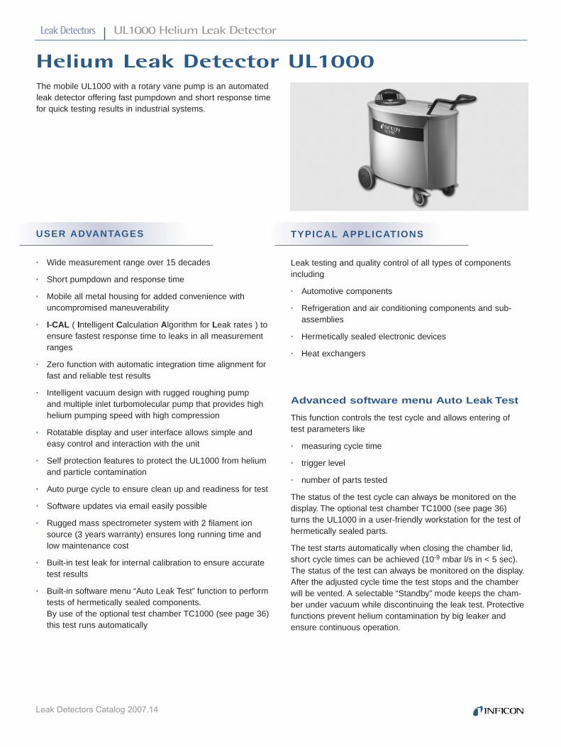
UL1000 Helium Leak Detector
USER ADVANTAGES
· Wide measurement range over 15 decades
· Short pumpdown and response time
· Mobile all metal housing for added convenience withuncompromised maneuverability
· I-CAL ( Intelligent Calculation Algorithm for Leak rates ) toensure fastest response time to leaks in all measurementranges
· Zero function with automatic integration time alignment forfast and reliable test results
· Intelligent vacuum design with rugged roughing pump and multiple inlet turbomolecular pump that provides highhelium pumping speed with high compression
· Rotatable display and user interface allows simple andeasy control and interaction with the unit
· Self protection features to protect the UL1000 from heliumand particle contamination
· Auto purge cycle to ensure clean up and readiness for test
· Software updates via email easily possible
· Rugged mass spectrometer system with 2 filament ionsource (3 years warranty) ensures long running time andlow maintenance cost
· Built-in test leak for internal calibration to ensure accuratetest results
· Built-in software menu “Auto Leak Test” function to performtests of hermetically sealed components.By use of the optional test chamber TC1000 (see page 36)this test runs automatically
Helium Leak Detector UL1000The mobile UL1000 with a rotary vane pump is an automatedleak detector offering fast pumpdown and short response timefor quick testing results in industrial systems.
TYPICAL APPLICATIONS
Leak testing and quality control of all types of componentsincluding
· Automotive components
· Refrigeration and air conditioning components and sub-assemblies
· Hermetically sealed electronic devices
· Heat exchangers
Advanced software menu Auto Leak Test
This function controls the test cycle and allows entering oftest parameters like
· measuring cycle time
· trigger level
· number of parts tested
The status of the test cycle can always be monitored on thedisplay. The optional test chamber TC1000 (see page 36)turns the UL1000 in a user-friendly workstation for the test ofhermetically sealed parts.
The test starts automatically when closing the chamber lid,short cycle times can be achieved (10-9 mbar l/s in < 5 sec).The status of the test can always be monitored on the display.After the adjusted cycle time the test stops and the chamberwill be vented. A selectable “Standby” mode keeps the cham-ber under vacuum while discontinuing the leak test. Protectivefunctions prevent helium contamination by big leaker andensure continuous operation.
INF_CatalogB5_0705 16.05.2007 14:59 Uhr Seite 14

Leak Detectors
Leak Detectors Catalog 2007.15
B5
UL1000 Helium Leak Detector
SPECIFICATIONS UL1000
UL1000, 230 Volts, 50 Hz, EU mains plug 550-000UL1000, 115 Volts, 60 Hz, US mains plug 550-001UL1000, 110 Volts, 60 Hz, Japan mains plug 550-002Test chamber TC1000 551-005Tool box with lock, attachable 551-000Helium bottle holder 551-001ESD mat 551-002Remote control kit
Hand unit 200 99 022Cable (required), 4 m length 200 99 027Extension cable, 10 m (max length of extension 34 m) 140 22
PC software LeakWare 140 90Sniffer line SL200, 4 m length 140 05
Min. detectable leak rate for helium (Vacuum mode) *) < 5 x 10-12 mbar l/sMin. detectable leak rate for helium (Sniffer mode) *) < 5 x 10⁻⁸ mbar l/sMax. detectable leak rate for helium that can be displayed 0.1 mbar l/sMax. inlet pressure GROSS mode: 15 mbar
FINE mode: 2 mbarULTRA mode: 0.4 mbar
Pumping speed during evacuation 16 m3/h (11.2 cfm) at 50 HzHelium pumping speed GROSS mode: max. 8 l/s
FINE mode: 7 l/sULTRA mode: 2.5 l/s
Time constant of the leak rate signal (blanked off, 63% final value) < 1 s
Pumpdown time until ready to detect leaks (Background 5 x 10⁻⁹)Without additional volume 5 sAt a test volume of 1 litre 10 sAt a test volume of 10 litre 80 s
Response time (for a leak rate of 10-9 mbar l/s)Up to a volume of 1 litre < 1 sUp to volume of 10 litre < 2 s
Time until ready for operation < 3 minDetectable masses 2,3,4Mass spectrometer 180° magnetic sector fieldIon source 2 filaments, Iridium/Yttria oxide coatedCalibrated leak TL7 (built-in) leak rate in the range 10-7 mbar l/sUnits of measurement (selectable) mbar l/s, Pa m3/s,Torr l/s, atm cc/s,
ppm, g/a (only in sniffer mode)Test port 25 KFAdjustable triggers 2Interface RS 232In/outputs PLC compatible for control and status informationChart recorder output 2 x 10 VSupply voltages 230 V (±10%) 50 Hz
115 V (±10%) 60 Hz100 V (±10 %) 50/60 Hz
Power consumption 1100 VADimensions (L x W x H) 1068 x 525 x 850 mm (42 x 21 x 33 inch)Weight 110 kg (242 lbs)Type of protection IP 40Permissable ambient temperature (during operation) +10 °C …..+40 °C*) per AVS and EN 1518
ORDERING INFORMATION PART NUMBER
INF_CatalogB5_0705 16.05.2007 14:59 Uhr Seite 15

Leak Detectors
Leak Detectors Catalog 2007.16
UL1000 Fab Helium Leak Detector
Dry Helium Leak Detector UL1000 FabThe mobile UL1000 Fab with its dry vacuum system is an automatic leak detector offering fast pumpdown and shortresponse time to meet the demanding requirements in semiconductor applications.
USER ADVANTAGES
· Wide measurement range over 15 decades
· Short pumpdown and response time
· Mobile all metal housing for added convenience withuncompromised maneuverability
· I-CAL (Intelligent Calculation Algorithm for Leak rates) toensure fastest response time to leaks in all measurementranges
· Zero function with automatic integration time alignment forfast and reliable test results
· Intelligent vacuum design with rugged scroll pump andmultiple inlet turbomolecular pump that provides high helium pumping speed with high compression
· Rotatable display and user interface allows simple andeasy control and interaction with the unit
· Self protection features to protect the UL1000 Fab fromhelium and particle contamination
· Auto purge cycle to ensure clean up and readiness for test
· Software updates via email easily possible
· Rugged mass spectrometer system with 2 filament ionsource (3 years warranty) ensures long running time andlow maintenance cost
· Built-in test leak for internal calibration to ensure accuratetest results
· Built-in software menu “Auto Leak Test” function to performtests of hermetically sealed components.By use of the optional test chamber TC1000 (see page 36)this test runs automatically
TYPICAL APPLICATIONS
· Leak testing of
· Components
· Chambers
· Subassemblies
used on
· Semiconductor tools
· Flat display tools
· Leak testing of hermetically sealed electronically devices
Advanced software menu Auto Leak Test
This function controls the test cycle and allows entering of testparameters like
· measuring cycle time
· trigger level
· number of parts tested
The status of the test cycle can always be monitored on thedisplay. The optional test chamber TC1000 (see page 36)turns the UL1000 in a user-friendly workstation for the test ofhermetically sealed parts.
The test starts automatically when closing the chamber lid,short cycle times can be achieved (10-9 mbar l/s in < 5 sec).The status of the test can always be monitored on the display.After the adjusted cycle time the test stops and the chamberwill be vented. A selectable “Standby” mode keeps the cham-ber under vacuum while discontinuing the leak test. Protectivefunctions prevent helium contamination by big leaker andensure continuous operation.
INF_CatalogB5_0705 16.05.2007 14:59 Uhr Seite 16

Leak Detectors
Leak Detectors Catalog 2007.17
B5
UL1000 Fab Helium Leak Detector
UL1000 Fab, 230 Volts, 50 Hz, EU mains plug 550-100UL1000 Fab, 100/115 Volts, 50/60 Hz, US mains plug 550-101Test chamber TC1000 551-005Tool box with lock, attachable 551-000Helium bottle holder 551-001ESD mat 551-002Remote control kit
Hand unit 200 99 022Cable (required ),4 m length 200 99 027Extension cable, 10 m (max length of extension 34 m) 14022
PC software LeakWare 14090Sniffer line SL200, 4m length 14005
Min. detectable leak rate for helium (Vacuum mode) *) < 5 x 10-12 mbar l/sMin. detectable leak rate for helium (Sniffer mode) *) < 5 x 10⁻⁸ mbar l/sMax. detectable leak rate for helium that can be displayed 0.1 mbar l/sMax. inlet pressure GROSS mode: 15 mbar
FINE mode: 2 mbarULTRA mode: 0.4 mbar
Pumping speed during evacuation 25 m3/h (17.6 cfm) at 50 Hz30 m3/h (21.1 cfm) at 60 Hz
Helium pumping speed GROSS mode: max. 8 l/sFINE mode: 7 l/s
ULTRA mode: 2.5 l/sTime constant of the leak rate signal
(blanked off, 63% final value) < 1 sPumpdown time until ready to detect leaks (Background 5 x 10⁻⁹)
Without additional volume 5 sAt a test volume of 1 litre 10 sAt a test volume of 10 litre 80 s
Response time (for a leak rate of 10 E-9 mbar l/s)Up to a volume of 1 litre < 1 sUp to volume of 10 litre < 2 s
Time until ready for operation < 3 minDetectable masses 2,3,4Mass spectrometer 180° magnetic sector fieldIon source 2 filaments, Iridium/Yttria oxide coatedCalibrated leak TL7 (built-in) leak rate in the range 10-7 mbar l/sUnits of measurement (selectable) mbar l/s, Pa m3/s,Torr l/s, atm cc/s
ppm, g/a (only in sniffer mode)Test port 25 KFAdjustable triggers 2Interface RS 232In/outputs PLC compatible for control and status informationChart recorder output 2 x 10 VSupply voltages 230 V (±10%) 50 Hz
115 V (±10%) 60 Hz100 V (±10 %) 50/60 Hz
Power consumption 1100 VADimensions (L x W x H) 1068 x 525 x 850 mm (42 x 21 x 33 inch)Weight 110 kg (242 lbs)Type of protection IP 40Permissable ambient temperature (during operation) +10 °C …..+40 °C*) per AVS and EN 1518
SPECIFICATIONS UL1000 FAB
ORDERING INFORMATION PART NUMBER
INF_CatalogB5_0705 16.05.2007 14:59 Uhr Seite 17

Leak Detectors
Leak Detectors Catalog 2007.18
UL5000 Helium Leak Detector
Dry Helium Leak Detector UL5000The mobile UL5000 is designed to meet the most critical and demanding semiconductor applications, providing fastpumpdown time and delivering fast response time.
It is an ideal tool for bigger testing volumes > 50 l volume.
TYPICAL APPLICATIONS
Leak testing of
· Components
· Bigger chambers (> 50 l volume)
· Subassemblies
used on
· Semiconductor tools
· Flat display tools
USER ADVANTAGES
· Wide measurement range over 15 decades
· Short pumpdown and response time
· Mobile all metal housing for added convenience withuncompromised maneuverability
· Software algorithm HYDRO·S (HYDROgen-Suppression)to enable test conditions to be reached quickly
· I-CAL (Intelligent Calculation Algorithm for Leak rates ) toensure fastest response time to leaks in all measurementranges
· Zero function with automatic integration time alignment forfast and reliable test results
· Intelligent vacuum design with rugged Sroll pump and multiple inlet turbomolecular pump that provides high helium pumping speed with high compression
· Rotatable display and user interface allows simple andeasy control and interaction with the unit
· Self protection features to protect the UL5000 from heliumand particle contamination
· Auto purge cycle to ensure clean up and readiness for test
· Software updates via email easy possible
· New workstation design with optimal height work surfacethat includes an ESD mat and a lockable tool box
· Rugged mass spectrometer system with 2 filament ionsource (3 years warranty) ensures long running time andlow maintenance cost
· Built-in test leak for internal calibration to ensure accuratetest results
INF_CatalogB5_0705 16.05.2007 14:59 Uhr Seite 18

Leak Detectors
Leak Detectors Catalog 2007.19
B5
UL5000 Helium Leak Detector
Min. detectable leak rate for helium (Vacuum mode) *) < 5 x 10-12 mbar l/sMin. detectable leak rate for helium (Sniffer mode) *) < 5 x 10⁻⁸ mbar l/sMax. detectable leak rate for helium that can be displayed 3 mbar l/sMax. inlet pressure GROSS mode: 15 mbar
FINE mode: 2 mbarULTRA mode: 0.4 mbar
Pumping speed during evacuation 25 m3/h (17.6 cfm) at 50 Hz30 m3/h (21.1 cfm) at 60 Hz
Helium pumping speed GROSS: max. 8 l/sFINE: max. 20 l/s
ULTRA: > 20 l/sTime constant of the leak rate signal (blanked off, 63% final value) < 1 sPumpdown time until ready to detect leaks in the range of 10-9 mbar l/s
Without additional volume < 5 sAt a test volume of 10 litre < 48 sAt a test volume of 50 litre < 150 s
Response time (for a leak rate of 10-9 mbar l/s )Up to a volume of 10 litre < 1 sUp to volume of 50 litre < 3 s
Venting (with test volume of 100 litres) approx. 25 sTime until ready for operation < 3 minDetectable masses 2,3,4Mass spectrometer 180° magnetic sector fieldIon source 2 filaments, Iridium/Yttria oxide coatedCalibrated leak TL7 (built-in) leak rate in the range 10-7 mbar l/sUnits of measurement (selectable) mbar l/s, Pa m3/s, Torr l/s, atm cc/s
ppm, g/a (only in sniffer mode)Test port 40 KFAdjustable triggers 2Interface RS 232In/outputs PLC compatible for control and status informationChart recorder output 2 x 10 VSupply voltages 230 V (±10%) 50 Hz
115 V (±10%) 60 Hz100 V (±10%) 50/60 Hz
Power consumption 1200 VADimensions (L x W x H) 1068 x 525 x 850 mm (42 x 21 x 33 inch)Weight 140 kg (308 lbs)Type of protection IP 40Permissable ambient temperature (during operation) +10 °C …..+40 °C*) per AVS and EN 1518
UL5000, 230 Volts, 50 Hz, EU mains plug 550-500UL5000, 100/115 Volts, 50/60 Hz, US mains plug 550-501Tool box with lock, attachable 551-000Helium bottle holder 551-001ESD mat 551-002Remote control kit
Hand unit 200 99 022Cable (required), 4 m length 200 99 027Extension cable, 10 m (max length of extension 34 m) 14022
PC software LeakWare 14090Sniffer Line SL200, 4 m 14005Reduction piece 40/25 KF to connect SL200 to UL5000 inlet port 211-283
SPECIFICATIONS UL5000
ORDERING INFORMATION PART NUMBER
INF_CatalogB5_0705 16.05.2007 14:59 Uhr Seite 19

Leak Detectors
Leak Detectors Catalog 2007.20
Protec P3000 Helium Sniffer Leak Detector
Helium Sniffer Leak Detector Protec P3000INFICON Protec P3000 Helium Sniffer Leak Detector isspecifically designed for full-time sniffing applications indemanding production environments.
The Protec P3000 brings increased levels of productivityand reliability to the sub-assembly and mid-production testing of refrigerators, freezers, air conditioners, auto-motive air conditioners, RAC components and similar products. Numerous features make it easy and comfortableto use, while making it more immune to careless or un-trained operation. It is also fast to make the best use of your available cycle time. Protec P3000 uses innovativeINFICON Wise Technology in its robust, reliable and maintenance-free sensor that combined with the uniquedesign and ruggedness of the leak detector, provides a very low cost of ownership and high up-time.
USER ADVANTAGES
· Improved system design compensates for operator errorreducing the potential for missed leaks.
· Multiple alarm functions make sure alarms can not beoverlooked.
· Built-in PRO-Check reference leak allows for easy and fast calibration at the production line at any time.
· A small display in the ergonomically-designed probe handle shows the leak rate, so the operator can concentrate on the sniffing process and monitoring the leak rate at the same time.
· I·Guide operator guiding mode ensures your operator istesting the right locations with the correct technique.
· Leak rates can be displayed in refrigerant equivalents from a gas library.
· Built-in illumination source of the probe helps preciselyposition the sniffer tip.
· New, low-maintenance sensor yields high reliability and low cost of ownership.
· Automatic standby prevents intake of contaminants into the sniffer probe, thus saving filter and sensor life.
· Operating software is available in many languages.
TYPICAL APPLICATIONS
The Protec P3000 is ideal for all helium sniffing applicationsof pressurized components that need to be leak tested.
· Refrigerating / air conditioning industries- Evaporators- Condensers- Valves- Compressors- Testing of pre-assembled air condition systems before
filling with refrigerant- Testing of pre-assembled refrigerators and freezers
before filling with refrigerant- Testing of pre-assembled heat pump systems before
filling with refrigerant
· Automotive industry- Brake lines- Fuel lines- Hydraulic components- Engines- Testing of pre-assembled air conditioning systems
before filling with refrigerant
Protec P3000RC with external display unit for rack mounting
INF_CatalogB5_0705 16.05.2007 14:59 Uhr Seite 20

Leak Detectors
Leak Detectors Catalog 2007.21
B5
Protec P3000 Helium Sniffer Leak Detector
Detectable gases Helium
Smallest detectable leak rate 1 x 10⁻⁷ mbarl/s
Measuring scale 5 decades
Sensor response time 450 ms
Response time incl. sniffer line < 0.7 s
Leak rate units mbar l/s; Pa m3/s; ppm
Refrigerant equivalent leak rates g/a; oz/yr; lb/yr
Start-up time < 3 min
Dimensions (width x depth x height) 610 x 265 x 370 mm24 x 10.4 x 14.6 in
Weight 27 kg (60 lbs)
Gas flow 300 sccm
Ambient temperature range 10-45°C (50-113°F)
Protec P3000230 V, 50 Hz 520-001110/115 V, 50/60 Hz 520-002
Protec P3000RC230 V, 50 Hz 520-103110/115 V, 50/60 Hz 520-104
Sniffer line with integrated display and push-buttonsSL3000-3, 3 m length 525-001SL3000-5, 5 m length 525-002SL3000-10, 10 m length 525-003SL3000-15, 15 m length 525-004
Sniffer line adapter for system integration 525-005Sniffer tips
ST 312, 120 mm, rigid 12213FT 312, 120 mm, flexible 12214ST 200, 200 mm, rigid 12218FT 250, 250 mm, flexible 12266ST 385, 385 mm, rigid 12215FT 385, 385 mm, flexible 12216FT 600, 600 mm, flexible 12209ST 400, 400 mm, 45° angled 12272
Holder for sniffer probe 525-006PRO-Check reference leak - optional(Not included with delivery of Protec P3000.) 521-001Display unit for Protec P3000RC
Table top version 551-100Rack version 551-101
Connecting cable for display unit, 5 m 551-102
Protec and Wise Technology are trademarks of INFICON.
SPECIFICATIONS PROTEC P3000
ORDERING INFORMATION PART NUMBER
INF_CatalogB5_0705 16.05.2007 14:59 Uhr Seite 21

Leak Detectors
Leak Detectors Catalog 2007.22
Ecotec E3000 Multi-Gas Leak Detector
Multi-Gas Sniffer Leak Detector Ecotec E3000The Ecotec E3000 leak detector brings new levels of productivity and reliability to the final testing of refrigerators,freezers, automotive air conditioners and similar products. It isspecifically designed for demanding production environments.Numerous features make it easy and comfortable to use whilemaking it more immune to careless operation and minimizingoperator errors. It is also fast to make the best use of youravailable cycle time. Innovative design and robustness keepthe cost of ownership down and ensure very high up-time.
USER ADVANTAGES
· Improved system design compensates for poor sniffingoperation reducing the potential for missed leaks
· IGS (Interfering Gas Suppression) ensures only leaks are detected
· Built-in ECO-Check reference leak allows for easy and fast calibration at the production line at any time
· Multiple alarm functions make sure alarms cannot be overlooked
· I·Guide (operator guiding mode) ensures your operatortests the right locations with the right technique
· Unit can be operated via the probe display and probe buttons without access to the main unit
· Built-in illumination source on the probe helps preciselyposition the sniffer tip
· Ergonomic probe design allows for easy and comfortableuse
· Operating software is available in many languages
TYPICAL APPLICATIONS
· Refrigerators and deep freezers
· Transportation refrigeration
· Cooling and refrigeration systems
· Air conditioning units
· Water coolers
· Compressors and evaporators
· Halogen lamps
· Gas panels
Ecotec P3000RC with external display unit for table top use
INF_CatalogB5_0705 16.05.2007 14:59 Uhr Seite 22

Leak Detectors
Leak Detectors Catalog 2007.23
B5
Ecotec E3000 Multi-Gas Leak Detector
Ecotec E3000, 230 V, 50 Hz 530-001100/115 V, 50/60 Hz 530-002
Ecotec E3000RC230 V, 50 Hz 530-103100/115 V, 50/60 Hz 530-104
Sniffer line with integrated display and push-buttonsSL3000-3, 3 m length 525-001SL3000-5, 5 m length 525-002SL3000-10, 10 m length 525-003SL3000-15, 15 m length 525-004
Sniffer line adapter for system integration 525-005Sniffer tips
ST 312, 120 mm, rigid 122 13FT 312, 120 mm, flexible 122 14ST 200, 200 mm, rigid 122 18FT 250, 250 mm, flexible 122 66ST 385, 385 mm, rigid 122 15FT 385, 385 mm, flexible 122 16FT 600, 600 mm, flexible 122 09ST 400, 400 mm, 45° angled 122 72
Holder for sniffer probe 525-006ECO-Check reference leak R134a - optional(Not included with delivery of Ecotec E3000.) 531-001Display unit for Ecotec E3000RC
Table top version 551-100Rack version 551-101
Connection cable for display unit, 5 m 551-102Test leaks for refrigerants (2 - 5 g/a)
R134a 122 20R600a 122 21R404A 122 22R502 122 23R22 122 25R152a 122 27R407C 122 28R410A 122 29R401a 122 30R290 122 31Forming gas (10% hydrogen, 90% helium) 122 33Halon 1301 122 34
Smallest detectable leak rate R134a 0.05 g/a (0.002 oz/yr)R600a 0.05 g/a (0.002 oz/yr)Helium 1 x 10⁻⁶ mbar l/s
Measuring scale 0.05 – 999.99 g/a (0.015 – 99.999 oz/yr)Sensor response time 0.3 sResponse time incl. sniffer line 0.8 sMax no. of gases detected simultaneously 4Leak rate units g/a, oz/y, mbar l/s, ppm, Pa m3/sGas flow 160 sccmStart-up time < 2 minAmbient temperature range 10 – 45 °C (50 – 113 °F)Dimensions (W x H x D) 610 x 370 x 265 mm (24 x 14.6 x 10.4 in)Weight 34 kg (75 lbs)
SPECIFICATIONS ECOTEC E3000
ORDERING INFORMATION PART NUMBER
INF_CatalogB5_0705 16.05.2007 14:59 Uhr Seite 23

Leak Detectors
Leak Detectors Catalog 2007.24
Ecotec E3000A Multi-Gas Leak Detector
Multi-Gas Leak Detector Ecotec E3000AThe Ecotec E3000A multi-gas leak detector is the reliable andlow-cost solution for testing cooling circuits in Airbus air-planes. Simpler and measurably faster than conventional leak-testing methods, the Ecotec E3000A does not require evacua-tion. It simply “sniffs” for refrigerant leaks while the system isin use, reducing downtime and waste. The Ecotec E3000A isrecommended for use in the A340 (for more information seeAMM chapter 25-34-00) and will also be recommended for the next-generation A380. It comes with a library of more than 100 detectable gases including all refrigerants and heat transfer fluids used in Airbus airplanes as well as many other commonly used gases.
USER ADVANTAGES
· Improved system design compensates for poor sniffingoperation reducing the potential for missed leaks
· Simpler and measurably faster than conventional testingmethods
· Does not require evacuation
· Less downtime for airplanes
· Fewer instances where food cannot be served because ofrefrigeration issues, resulting in better customer service
· Pinpoints the exact location of the leak
· Detected leak rate can be read from the probe display asnumerical value
· Can detect up to four different gases at the same time
· Built-in, adjustable illumination helps operators preciselyposition the tip even in tight compartments where light islimited
· Wheeled transportation case that holds all accessories tobe easily hauled around the airplane
· Recommended in AMM A340, Chapter 25
TYPICAL APPLICATIONS
Leak testing of
· Galley systems
· Transfer lines
· Main chiller system
· Air conditioning system
INF_CatalogB5_0705 16.05.2007 14:59 Uhr Seite 24

Leak Detectors
Leak Detectors Catalog 2007.25
B5
Ecotec E3000A Multi-Gas Leak Detector
Ecotec E3000A including:
5 m sniffer line, power plug adapter for all major regions, 120 mm rigid sniffer tip, 385 mm flexible sniffer tip, built-in ECO-Check reference leak, transportation case
230 V, 50 Hz 530-101100/115 V, 50/60 Hz 530-102
Smallest detectable leak rate 0.05 g/a (0.02 oz/yr)Measuring scale 0.5 – 50 g/a (0.02 – 1.76 oz/yr)Response time < 1sLeak rate units g/a; oz/yr; lb/yr; mbar l/s; Pa m3/s Start-up time < 2 minMax no. of gases detected simultaneously 4Interfaces RS232Dimensions (diameter; height) 580 x 260 x 350 mm (22.8 x 12.2 x 13.8 in)Weight 34 kg (75 lbs)Gas flow 160 sccmAmbient temperature range 10-45 °C (50-113 °F)Software available in English, German, Spanish, French, Italian, Portugese,
Chinese, Japanese (Katakana)Warranty 2 years
SPECIFICATIONS ECOTEC E3000A
ORDERING INFORMATION PART NUMBER
INF_CatalogB5_0705 16.05.2007 14:59 Uhr Seite 25

Leak Detectors
Leak Detectors Catalog 2007.26
HLD5000 Refrigerant Leak Detector
Refrigerant Sniffer Leak Detector HLD5000 The HLD5000 refrigerant leak detector uses an innovativetechnology to find leaks quickly and reliably with dramaticallyfewer false alarms.
With its IR sensor it is designed to only detect refrigerantleaks. It reliably suppresses any signals caused by othergases present in the atmosphere. Numerous other featuresenhance the units convenience, reliability and durability.A selection of probes for single gases as well as a universalprobe for all halogen-based refrigerants is available.
USER ADVANTAGES
Highly reliable detection of leaks
· No false alarms due to background compensation by dualinlet technology
· No cross sensitivity to non-halogens (water, breath, alcohols, etc)
· No undetected leaks due to undetected malfunctioning ofthe leak detector as functionality is constantly monitored
· Short response time for fast use
Universal base unit for high flexibility
· Universal base unit with different probes
· Selection of different probes for single refrigerants including non-halogens (CO2, SF6)
· Universal probe for all halogen-based refrigerants
· Unit can be switched over by simply connecting a differentsniffer line
Easy to operate
· ATM-like display
· Visual (probe and base unit) and acoustic alarm
· Integrated test leak for easy and traceable calibration atthe line as well as regular verification of the calibration
· May be used in automated testing systems with digital processing of test data via RS232 interface
Low cost of operation
· Reliable operation of the unit and very low cost of operation
· Long sensor life, resistant to water intake
TYPICAL APPLICATIONS
· Air conditioning systems
· Automotive air conditioning units
· Heat pumps
· Compressors and tubing
· CO2 components
· Components or systems filled with SF6
INF_CatalogB5_0705 16.05.2007 14:59 Uhr Seite 26

Leak Detectors
Leak Detectors Catalog 2007.27
B5
HLD5000 Refrigerant Leak Detector
HLD5000 including hand piece, sniffer tip (100 mm, 3.9 in.) and calibrated leak
R134a 510-010R744 (CO2)* 510-015SF6* 510-016Universal Smart probe 510-017
Additional sniffer line for different refrigerantsR134a 511-030R744 (CO2) 511-035SF6 511-036Universal Smart probe 511-037
Replacement calibrated leak COOL-CHECK 511-010Extra sniffer tip, 100 mm (3.9 in.) 511-021Extra sniffer tip, 400 mm (15 in.) 511-024Extra extension, 400 mm (15 in.) for sniffer tip 511-020Extra extension, 500 mm (19.7 in.) for sniffer tip, 45° offset 511-029Set of tip filter holders (20 pcs) 511-027Set of filter cartridges (20 pcs) 511-018Test leaks for refrigerants (2 - 5 g/a)
R134a 12220R404A 12222R407C 12228R410a 12229R744 (CO2) 12232
*without calibrated leak COOL-Check
Detectable refrigerant (depends on version) R134a; R404A; R407C; R410A; R22; R744 (CO2); SF6;all halogen-based refrigerants
Min. detectable leak rate for single gas probes 1.0 g/afor universal probe 0.5 g/a
Measuring scale 0.5 - 50 g/aResponse time < 1 sLeak rate units mbar l/s, g/a, oz/y, Pa m3/s, lb/yrWarm-up time 30 sDimensions (diameter; height) 260 mm; 14.4 in.Weight 4.5 kgLength of sniffer line 4.8 mSniffer tip length 100 mmGas flow 320 sccmAmbient temperature range 5 - 50 °C
SPECIFICATIONS HLD5000
ORDERING INFORMATION PART NUMBER
INF_CatalogB5_0705 16.05.2007 14:59 Uhr Seite 27

Leak Detectors
Leak Detectors Catalog 2007.28
Accessories
Calibrated Test LeaksIn order to perform reliable quantitative measurements ofleak rates, the used leak detection equipment must be cali-brated by inlet of a known leakage flow delivered by a testleak.
USER ADVANTAGES
· Highly accurate and reliable due to the profile of the quartz capillary
· Metal-free capillary for low temperature dependance
· Inspection certificate (included) in accordance to DIN EN 10204:2004-3.1
Calibrated Test Leakswith Gas Reservoir for Sniffer ApplicationsThe function of these leaks is based on a special quartzcapillary which is customized to deliver a specific reducedflow from a test gas reservoir.This type of calibrated test leaks is available in different leakrates and test gases (see ordering information).
CALIBRATED LEAK LEAK RATE RANGE PART NUMBER
S-TL 4, with helium gas reservoir 10-4 mbar l/s 122 37S-TL 5, with helium gas reservoir 10-5 mbar l/s 122 38S-TL 6, with helium gas reservoir 10-6 mbar l/s 122 39Calibrated sniffer test leaks for refrigerants
2 - 5 g/a, 0.07 - 0.18 oz/y R22 122 25R134a 122 20R152a 122 27R290 122 31R401a 122 30R404a 122 22R407c 122 28R410a 122 29R502 122 23R600a 122 21R744 (CO2) 122 3210% H2 / 95% He 122 33R13B1 (Halon 1301) 122 34
10 - 14 g/a, 0.36 - 0.5 oz/y R134a 122 40R404a 122 42R502 122 43R600a 122 41
ORDERING INFORMATION
· Determination of the nominal leak rate by comparison with a calibrated leak having a PTB certificate
· DKD certificate (optional) traceable to PTB
INF_CatalogB5_0705 16.05.2007 14:59 Uhr Seite 28

Leak Detectors
Leak Detectors Catalog 2007.29
B5
Accessories
USER ADVANTAGES
· Inured to pollution
· Metal-free flow reduction for low temperature dependence
· Inspection certificate (included) in accordance to DIN EN 10204:2004-3.1
Calibrated Test Leaks with with Gas Reservoirfor Vacuum ApplicationsTL7
Capillary leak with helium reservoir and manual valve.Leak rate range 10-7 mbar l/s.
TL8 / TL9
Helium test leak with helium reservoir and manual valve.A special quartz bulb with a high helium permeation rateadjusts the constant gas flow.
CALIBRATED LEAK LEAK RATE RANGE PART NUMBER
TL 7, with helium gas reservoir 10-7 mbar l/s 142 10 / 115 14TL 8, with helium gas reservoir 10-8 mbar l/s 165 57TL 8, with helium gas reservoir, DKD calibrated 10-8 mbar l/s 165 57DKDTL 9, with helium gas reservoir 10-9 mbar l/s 144 08
ORDERING INFORMATION
· Highly accurate and reliable
· Determination of the nominal leak rate by comparison with a calibrated leak having a PTB certificate
· DKD certificate (optional) traceable to PTB
Calibrated Test Leaks with with Gas Reservoirfor Vacuum and Sniffer ApplicationsTL4-6
Universal gas source for the fast insert in a variety of applications
Helium capillary leak for vacuum and sniffing applications.Adjustable leak rate in the range between 10-4 to 10-6 mbar l/s. Besides helium, which is included in delivery, the TL4-6 is also usable with different kind ofgases.
CALIBRATED LEAK LEAK RATE RANGE PART NUMBER
TL4-6, with helium gas reservoir 10-4 to 10-6 mbar l/s 155 80
ORDERING INFORMATION
INF_CatalogB5_0705 16.05.2007 14:59 Uhr Seite 29

Leak Detectors
Leak Detectors Catalog 2007.30
Leak rate range
Leak rate as a function of applied test pressure vs. 0 bar
Accessories
Calibrated Leaks for System ApplicationsManufacturers of helium leak testing systems require calibrated leaks of various sizes with individually adjusted leak rates for the purpose of setting up and calibrating theirsystems.
Depending on the type of application, these calibrated leaksare either installed in the test sample as a master leak or areinstalled in the test chamber itself.
INFICON offers a family of calibrated leaks which are capableof meeting the requirements concerning type and requiredleak rate.
Calibrated leaks with screw-in sleeve (left), pin-type casing (center), cylindrical casing (right)
USER ADVANTAGES
· Various types adapted to different customer requirements
· Simple to operate
· Easy to install
· Ideal installation dimensions
· All calibrated leaks are supplied with a factory certificateindicating their leak rate
TYPICAL APPLICATIONS
· As a master calibrated leak built directly into the test sample
· Directly installed to the test chamber
· Use as a calibrated leak for sniffer applications
Integral test leak
Test pressure pV
Lea
k ra
te q
L
B5
INF_CatalogB5_0705 16.05.2007 14:59 Uhr Seite 30

Leak Detectors
Leak Detectors Catalog 2007.31
B5B5
Accessories
Calibrated leak with screw-in sleeve
Calibrated leak with pin type casing and VCO fitting
Calibrated leak with pin type casing and hose nozzle
Calibrated leak with cylindrical casing and VCO fitting
CALIBRATED LEAK WITH SCREW-IN SLEEVE
Used as a master leak to check the entire helium leak testingsystem.
Two leak tight test samples are equipped with these calibratedleaks. These will ensure proper separation between passedand rejected parts. To be fitted to the customer’s test sampleseither by a welded joint or the screw-in sleeve is glued inplace.
CALIBRATED LEAK WITH PIN TYPE CASING
Serves as a calibrated leak for the entire helium leak testingsystem without being influenced by the presence of a testsample.
Here a dummy is placed in the test chamber. The connectionto the test chamber is directly by a DN 10 KF fitting. The testgas connection is either by a VCO fitting or a 10 mm hosenozzle for flexible connections.
CALIBRATED LEAK WITH CYLINDRICALCASING
The test gas connection is either by a VCO fitting or a 10 mmhose nozzle for flexible connections.
All calibrated test leaks for systems are designed for a max.working temperature of 80 °C.
CALIBRATED INTEGRAL LEAK WITH HELIUMRESERVOIR
The integral Helium test leak is for use in a vacuum testchamber and is designed for easy filling and refilling by thecustomer. It is used for
- Calibration of the vacuum system- Evaluation of the machine factor for the system- Verification of the test procedure Integral test leak
CALIBRATED INTERNAL LEAK MAX. OPERATING PRESSURE PART NUMBER
Integral test leak 1 bar against vacuum 143 15SCalibrated leak with screw-in sleeve 20 bar (up to 40 bar if the
capillary is glued-in by the customer) 143 00Calibrated leak
with pin-type casing and hose nozzle 6 bar 143 08casing only 143 07
Calibrated leak with pin-type casing and VCO fitting 6 bar 143 04casing only 143 03
Calibrated leak 20 bar (up to 40 bar if thewith cylindrical casing and VCO fitting capillary is glued-in by the customer) 143 12casing only 143 11
ORDERING INFORMATION
B5
INF_CatalogB5_0705 16.05.2007 14:59 Uhr Seite 31

Leak Detectors
Leak Detectors Catalog 2007.32
SPECIFICATIONS
Accessories
Sample Probes (Sniffers) and AccessoriesHelium sniffers in connection with the UL1000, UL5000 andthe Modul1000 leak detectors are used for leak testing test samples in which a helium overpressure is present.Besides pinpointing the leaks, it is possible to determine theleak rate of the escaping helium.
Helium sniffer line SL 200 P
Helium sniffer QUICK-TEST QT 100 with sniffer
Test chamber TC1000
HELIUM SNIFFER LINE SL200 FOR THE UL1000/5000 ANDMODUL1000
· Sniffer line connects directly to the inlet port
· Very fast response
· Extremely low detection limit < 1 x 10⁻⁷ mbar l/s
· Rigid 120 mm sniffer tip (included)
HELIUM SNIFFERS QUICK-TEST QT100 FOR THE UL1000/5000,AND THE MODUL1000
· For greater distances up to 20 m between test object and leak detector
· Diaphragm pump for sucking the search gas
· Smallest detectable leak rate 1 x 10⁻⁶ mbar l/s
· Short response and decay times
· High sniffer velocity
· Built-in transformer for adaptation to any required power supply voltage
TEST CHAMBER TC1000 FOR THE UL1000/UL1000 FAB ANDMODUL1000
· Turns the UL1000 / UL1000 FAB and the Modul1000 into a reliable and user-friendly workstation for testing of hermetically sealed parts (also according to MIL-STD 843, Method 1014)
· Easy to install
· Maintenance-free
· Volume (hemispherical shape): approx. 430 ccm
· Upper diameter / depth: 130 / 40 mm
· Material: Aluminum alloy, low outgasing rate
· Weight: 2.5 kg
· Vacuum connection: DN 25 KF
· Integrated sensor switch to start test in combination with UL1000 / UL1000 Fab and the Modul1000
· Clearly visible red/green LED’s to display test results
· Calibration by an external test leak easy possible by using an optional adapter plate
· Protection of tested parts against static discharge by the standard ESD wrist band and an optional ESD mat (Cat. No. 551-002) for UL1000 / UL1000 Fab
TC1000 in operation; exemplary menufunction showed on the display
INF_CatalogB5_0705 25.05.2007 10:09 Uhr Seite 32

Leak Detectors
Leak Detectors Catalog 2007.33
B5B5SAMPLE PROBES
SL200 QT100
Accessories
Helium sniffer line, SL200 P,4 m long, straight handlewith red / green LED for go / no-go indication,rigid sniffer tip 120 mm 140 05
Helium sniffer QUICK-TEST QT100 155 94Test chamber TC1000 incl. ESD wrist band 551-005Test leak adapter for TC1000, DN 25 KF flange 200 001 797Sniffer line adapter for system integration 525-005Sniffer line for the QT100, 5 m 140 08
20 m 140 09PC software LeakWare 140 90Search gas spray gun 165 55Rubber bladder (Helium reservoir for spray gun) 200 20 218Hose clamp for rubber bladder 200 20 217
Smallest detectable leak rate < 10-7 mbar l/s 10-6 mbar l/sSupply voltage - 110 - 220 V, 50/60 HzSignal response time, approx.
at a length of 5 m < 1 s 1 s20 m - 8 s
Connection flange DN 25 KF DN 25 KFWeight 0.6 kg (1.32 lbs) 3.5 kg (7.72 lbs)
SPECIFICATIONS
ORDERING INFORMATION PART NUMBER
Search gas spray gun
SNIFFER LINE ADAPTER FOR PROTEC P3000 AND ECOTEC E3000
Sniffer line adapter for system integration matching to Protec P3000 Helium leak detectors andEcotec E3000 multi-gas leak detectors.
SEARCH GAS SPRAY GUN
The search gas spray gun with PVC hose (5 m long) is used for well aimed spraying of searchgas at places where a leak is suspected.
PC SOFTWARE LEAKWARE
Windows PC software used for data acquisition, documentation of measurements,and to control the operation of the leak detector.
Sniffer line adapter
INF_CatalogB5_0705 16.05.2007 14:59 Uhr Seite 33

Leak Detectors
Leak Detectors Catalog 2007.34
Accessories
LEAK DETECTORS HELIUM SNIFFERS CALIBRATED LEAKUL1000 – DN 25 KF SL200 – DN 25 KF TL8 – DN 10 KF
UL1000 Fab – DN 25 KF SL200 – DN 25 KF TL8 – DN 10 KF
UL5000 – DN 40 KF SL200 – DN 25 KF* TL8 – DN 10 KF* Reducer for connection required
Connection Flanges
Connection ComponentsWhen connecting accessories (helium sniffer probe and calibrated leaks) to a vacuum leak detector, the following reducers and components may be necessary:
Reduction Reducers Centering RingsStainless steel / FPM
DN 25 / 16 KF Part No. 211-281, stainless steel DN 16 KF, Part No. 211-066
DN 40 / 25 KF Part No. 211-283, stainless steel DN 40 KF, Part No. 211-070
DN 40 / 16 KF Part No. 211-282, stainless steel DN 40 KF, Part No. 211-070
The following metal hoses are recommended to connect theleak detectors to systems:
Nominal Width Length Part NumberDN 16 KF 1.0 m 211-338
DN 16 KF 0.5 m 211-336
DN 25 KF 1.0 m 211-342
DN 25 KF 0.5 m 211-340
DN 40 KF 1.0 m 211-346
DN 40 KF 0.5 m 211-344
If components of the same nominal width are connected, onlyone centering ring and one clamping ring is required.
INF_CatalogB5_0705 16.05.2007 14:59 Uhr Seite 34

B5
INF_CatalogB5_0705 16.05.2007 14:59 Uhr Seite 35

12,7 / 207,127
www.inf icon.com reachus@inf icon.comDue to our continuing program of product improvements, specifications are subject to change without notice.
mila01e1-f (0704) ©2007 INFICON
INF_CatalogB5_0705 16.05.2007 14:59 Uhr Seite 36