
Turbines for very low head - NTNU · Turbines for very low head Torbjørn K. Nielsen 14.okt 2005...
29
Turbines for very low head Torbjørn K. Nielsen 14.okt 2005
Transcript of Turbines for very low head - NTNU · Turbines for very low head Torbjørn K. Nielsen 14.okt 2005...

Turbines for very low head
Torbjørn K. Nielsen14.okt 2005

• The oldest known text that mentions a water-powered machine is over 2000 years old
• Norse mills had then already been used for a long time in the mediterraneancountries
Vitruvius mill with gear

Ramelli 1588 Barker 1740Segner 1750
Besson 1568

• 1750 J.A.Segner – reaction turbine• 1750-54 Euler develops the turbine theory• 1827 Forneyron - radial turbine, 30 – 40 hp, D = 0.5 m• 1840 Henschel/Jonval – aksial turbine
Jonval – draft tube• 1849 Francis – Francis turbine
Fink – Load regulation with guide vanes• 1890 Pelton – Pelton turbine, impilse turbine• 1913 Kaplan – Kaplan turbine, propeller
Turbine development – modern time

• 1855: J. B. Francis presents a inward-flow turbine
• Hydraulically well-shaped vanes and blades
• Efficiency equal to Fourneyron and Jonval turbines
• 1873: Voith and Kankelwitz addadjustable guide vanes
Francis turbin

• 1926: First large Kaplan turbineinstalled at Lilla Edet
• Efficiency up to 92,5%• Part load efficiency above 83%• Final break-trough for Kaplan turbines
Kaplan

Pelton turbine – impulse turbine

Fourneyron turbine Jonval-Henschel turbine
The Girard turbine
Thomson
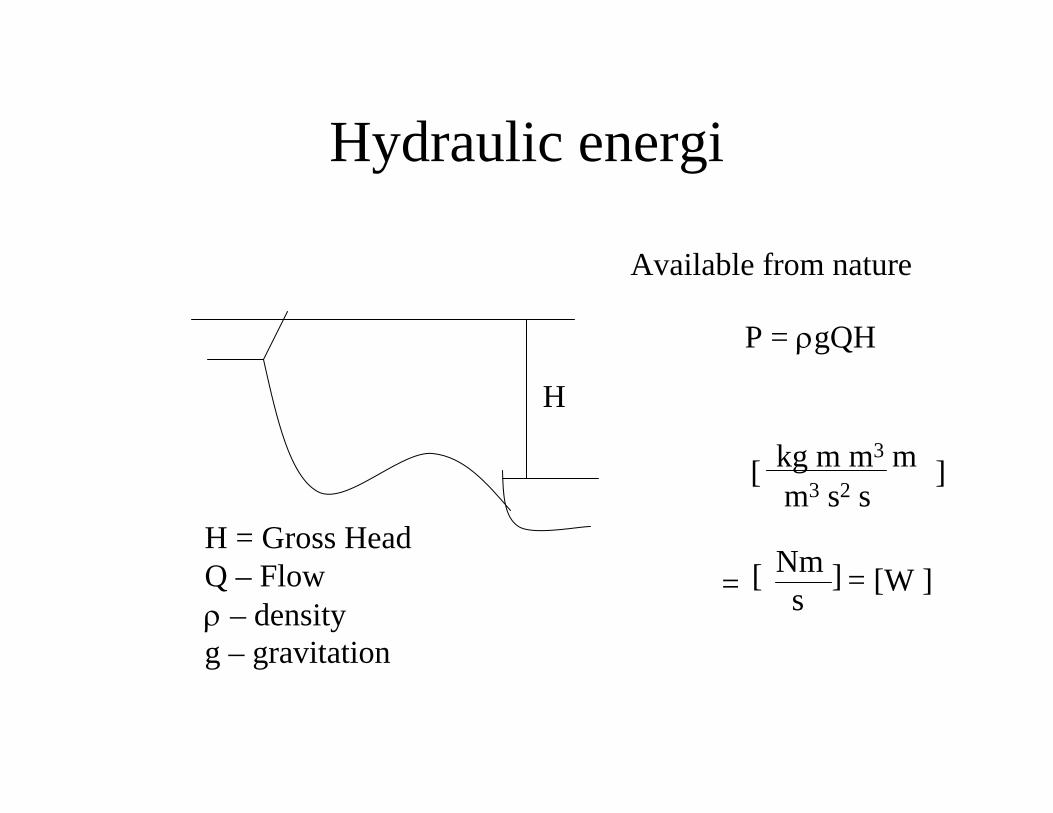
Hydraulic energi
P = ρgQH
kg m m3 mm3 s2 s
[ ]
=Nms = [W ][ ]
H = Gross HeadQ – Flowρ – densityg – gravitation
H
Available from nature

Power transformation
UIMgQH ⇒⇒ ωρ
Hydraulic power
Mechanical rotating power
Electric energy
Turbine Generator
⇒⇒

cu1
cu2c1
c2
o
v1v2
u1
u2
)( 2211 uu cucuQP −= ρ
Velocity components
ω
u – peripheral velocityv – relative velocityc – absolute velocity
vuc +=

u1
v1
v2
c1
c2
u2
Inlet – and outlet velocity triangle
β2
α1 β1
Runner vane
Guide vane

Dimensionless velocities
All velocities are scaled related to the velocity of”Toricellis theorem” - Reduced velocities:
He
e
e
e
gHcv
gHcu
gHcc
2
2
2
=
=
=
egH2

Hydraulic efficiency:
enatur
uu
gQHPcucuQTP
ρρω
=−== )( 2211
naturh P
P=η
e
uu
e
uuh gH
cucugQH
cucuQ )()( 22112211 −=
−=
ρρη
)( 2211 uuhe cucugH −=η
Or:

Introducing reduced velocities:
)(12211 uueh cucu
gH −=η
ee gHgH 21
21
)22
(12
2211
e
u
e
u
e
eh
gHcu
gHcu
ggHH
−=η
( )22112 uuh cucu −=η

Redused flow:
Redused angular speed:
[ ]2
2m
gHQQ
e
=
⎥⎦⎤
⎢⎣⎡=mgHe
12ωω
Then the following equations still applies:
ω=
=
u
cAQ

Speed number – classification of turbinesGeometric similar turbines but different in size, Shall have the same specification – a speed number
Two geometric similarturbines has the same redusedvelocity triangles:
12
22
:1.
1:2.
konstkonstQ
eqinPut
konstDeqFrom
=
=
ω
ω
cm
cmD
2
122
)24
)1
konstDDu
konstDQ
D
Qcm
=⇒=
=⇒=
ωω
π
konstQ =ω
Qω=Ω Speed number

The turbine must be designet optimal for a given operational point defined by:Q, H og w (or RPM) *- denotes BEP :
Q*** ω=Ω
Another classification number is ”spesific speed ”:
4/3HQn
nq =
Ω= *89qn

How the form of a turbine changes with the speed number:
Speed number: Qω=Ωee gH
QgH 22ω
=Ωeller:
2
22
22
2
44 m
m
c
QD
D
Qc ππ =⇒=
D2
cm2
ωω egH
uDDu22
2 111
1 =⇒=
D1
The redused velocities areapproximate constant
B
momo cD
QBcBDQ
11 π
π =⇒=
cmo
Incresed speed number: D2 andB increases

Turbine types
∗Ω=0.1 ∗Ω =0.2 ∗Ω =0.4 ∗Ω =1.0 ∗Ω =2.5
ChoosePelton
To much friction
KAPLAN: ∗Ω = 1.5 − 2.5FRANCIS: ∗Ω = 0.2 − 1.2PELTON: ∗Ω = 0.08 − 0.15


TurbindimensjonerLavtrykks vannkraft:
H 3 3 5 5 m 35 mQ 5 10 10 100 m3/s 80 m3/sPolpar 15 20 14 40 10n 200 150 214,2857 75 RPM 300 RPMeta 0,8 0,8 0,8 0,8 0,8Effekt 117,84 235,68 392,8 3928 kW 21996,8 kW
w 20,94 15,71 22,44 7,85 rad/s 31,42 rad/ssqrt(2gH) 7,67 7,67 9,90 9,90 m/s 26,20 m/s
Qred 0,65 1,30 1,01 10,10 3,05wred 2,73 2,05 2,27 0,79 1,20
Fartstall 2,20 2,34 2,28 2,52 2,09
u2 40,00 40,00 40,00 40,00 m/s 40,00 m/sD2 3,82 5,09 3,57 10,19 m 2,55 m

Turbin i fri strøm
32
VACP RV
P ⋅=ρ
0 5 10 150
1
2
3
4
Rotor radius [m]
Effe
kt [M
W]
3 m/s 2.5 m/s
2 m/s 1.5 m/s
Cp ≈ 0.4

Wells turbinen
• Luftturbin• Roterer samme vei uansett
retning på strømningen• Negativt startmoment

Voith-Schneider propellDarrius turbin

SeawaveSeawave SlotSlot--Cone Cone
• Turbin:1-3 m fallhøyde
• Flertrinns

Turbin
Ledeskovler
SugerørSug
erør
skon
us
Generator Utgangspunkt: Jonval turbin
• Uten sugerøret avløpstap:
• Gjenvinnes i sugerøret
mg
ch 62,062,195,3
2
22
===Δ

• Low head gives– low speed of rotation– huge dimensions on turbine and
generator– High torque
• How to increase head?– Amplification– Displacement pump

Q
t
Peltonturbin
SynkrongeneratorAkkumulator
• En- eller to strålers PeltonH = 155 mQ = 46 l/sP = 5,6 kW
• Turtall 1500• Diameter 340mmEller:• Turtall 3000 o/min• Diameter 170 mm


![Pelton Turbines [Compatibility Mode]](https://static.fdocuments.in/doc/165x107/55cf92f8550346f57b9ab6bd/pelton-turbines-compatibility-mode.jpg)


