Turbine Blade Fixture for Inspection and Grinding
69
Turbine Blade Fixture for Inspection and Grinding Team 33: Blades & Lasers Patrick Maloney, Nick Moroz, Craig Stanfill, Nick Zalenski ME450, Winter 2008 Section 7: Dr. Lalit Patil 15 April 2008
Transcript of Turbine Blade Fixture for Inspection and Grinding

Turbine Blade Fixture for Inspection and Grinding Team 33: Blades & Lasers
Patrick Maloney, Nick Moroz, Craig Stanfill, Nick Zalenski
ME450, Winter 2008 Section 7: Dr. Lalit Patil
15 April 2008

2
EXECUTIVE SUMMARY The turbine blade inspection station is designed to detect imperfections of 100-200 microns in size, using
a laser which has a precision on the submicron level. In order for this process to work properly, the
fixture must be repeatable on a very precise scale. As much of the blade as possible should be exposed so that the laser can inspect the entire blade. The fixture must also be able to withstand grinding forces
without allowing much movement of the turbine blade. The inspection station will eventually be placed
on the factory floor, so it must be robust, easy to use, and be quick to load and unload.
SPECIFICATIONS Each blade mounted on the fixture must be repeatable within +/- 20 microns. The
fixture must not occlude the grinder or the laser, which scans the blade’s surface. The fixture must also
be able to withstand grinding forces while staying within the 20 micron requirement. While this will presumably take a large amount of force at the base of the turbine blade, neither the blade nor the fixture
may plastically deform. The fixture must be able to be loaded within 20 seconds, a third of the current
load time at GE, and it must fit the bolt pattern on the turntable. The inspection station will be subject to
temperature changes of approximately 10°F, and all design specifications must be met throughout this temperature range.
PROBLEM ANALYSIS The greatest challenge of the design is creating a mechanism that does not
occlude the laser scanning device or the robotic grinder. The blade can only be fixtured at the base or up the finished sides of the blade that are not where scanning or grinding will occur. When a new blade is
placed in the fixture, the location of the blade at every point must be repeatable within an absolute vector
of 20 microns. While the grinder is modifying the blade in the fixture, the blade’s deflection must be minimized. The blade is on a rotating table with a bolt pattern, and the fixture must match this pattern to
be mounted to the table and the center of mass of the blade and the fixture must be over the center of the
bolt pattern with the blade upright for scanning and grinding. In addition to fulfilling these requirements, the fixture must be lightweight, easy and quick to operate.
CONCEPT GENERATION A functional decomposition was done in order to determine sub functions
of the fixture. Brainstorming by the team resulted in several means to accomplish each sub function.
Once these means were established the logical combinations were developed for each feature which resulted in approximately twenty concepts. Of these, the five best concepts were chosen and evaluated
against the customer requirements using the Pugh chart. Ultimately, an α-design was developed by
combining key features from multiple concepts.
FINAL DESIGN The α-design was later refined and a final design has been fabricated. The fixture was
created using standard machining techniques and is predominantly made of aluminum alloys. All parts
that were not ordered from a supplier as stock items were machined to high accuracy. The parts were then finished and inspected for quality. The fixture was assembled and installed on the turntable in the
ERC lab.
VALIDATION The fabricated fixture was tested using the laser scanner and multiple turbine blades. The
data was analyzed and the repeatability of the fixture to hold a turbine blade was an absolute difference of
37 microns, which falls within the +/- 20 micron requirement. The fixture is fully-functioning and
successfully accomplishes securing the turbine blade under the loading conditions of grinding and inspection. The fixture complies with all specifications and will be used by the ERC lab to inspect
turbine blades with high precision and efficiency. The fixture is now ready to be used as it was intended.
3
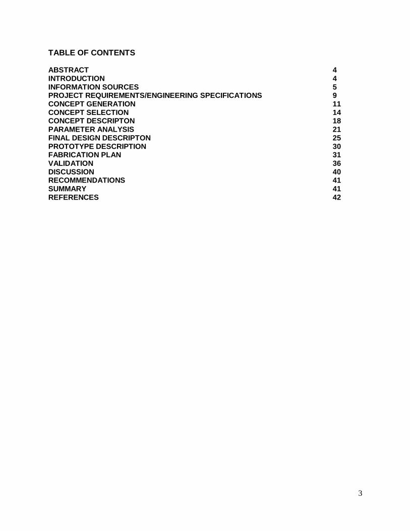
TABLE OF CONTENTS ABSTRACT 4 INTRODUCTION 4 INFORMATION SOURCES 5 PROJECT REQUIREMENTS/ENGINEERING SPECIFICATIONS 9 CONCEPT GENERATION 11 CONCEPT SELECTION 14 CONCEPT DESCRIPTON 18 PARAMETER ANALYSIS 21 FINAL DESIGN DESCRIPTON 25 PROTOTYPE DESCRIPTION 30 FABRICATION PLAN 31 VALIDATION 36 DISCUSSION 40 RECOMMENDATIONS 41 SUMMARY 41 REFERENCES 42

4
1. ABSTRACT
A given turbine blade is inspected using a high precision laser while mounted on a turntable. When a
defect is detected, material is removed using a robotic grinder. The blade must be held at the base, as to
not occlude the laser or grinder. The location and orientation of the blade in the fixture must be repeatable to a very high level of precision. The fixture must also be easy and quick to load and unload.
2. INTRODUCTION 2.1 PROBLEM BACKGROUND Turbine blades are typically inspected and modified in separate
processes, each of which requires a different fixture for each application. In order to optimize production,
the Engineering Research Center (ERC) at the University of Michigan is seeking a single fixture that
allows for inspection by laser scanner and modification through a grinding process. This fixture should be designed for gas turbine blades manufactured by TTC and utilized by GE in gas turbine engines.
The prototype built will be immediately used in the ERC lab on a turntable built by Aerotech Inc. The
turntable has a bolt pattern that the fixture will utilize. A laser attached to a three-axis motion system will inspect the critical surfaces of the turbine blade. The laser will detect defects of 100-200 microns in size
by comparing its scan with a CAD model of the blade. The ERC has created a system which transforms
the physical coordinate system to that of the CAD model. The turntable is supported by a robot which can rotate the turntable up to 45 degrees from horizontal, and the grinding forces applied by the robot can
be up to 5 lbs of force.
Figure 1: Orientation of blade in fixture and also showing the rotation of the turntable while
suspended by the robot during grinding.
2.2 PROBLEM ANALYSIS The most significant challenge is creating a fixture that will repeatedly
hold the turbine blade in the same orientation while not occluding the laser from inspecting any key
surfaces of the blade for defects. This limits our fixture design to only contact the lower surfaces and the
machined locator pins on the base of the blade, as well as up the sides of the blade where the machining processes have been completed which allows us to use latches higher up on the blade to increase precision
when grinding. The goal of this fixture is to repeatedly hold the turbine blade to within an absolute error
vector of 20 microns. To test the repeatability of the blade’s position in the fixture, the blade will be
placed in the fixture and a chosen surface on the blade will be scanned. The blade will be removed and reinserted with 5 lbs of force applied to critical areas and the laser will generate a second scan of the same
area which will be compared to the first.
The engineering fundamentals that will govern the design concepts and completion will be jig and fixture
design, material properties, manufacturing processes, and static mechanics. All of these concepts will be
Turntable Fixture
Turbine Blade
45 degrees 45 degrees

5
integral in determining how the blade will be positioned and held in the fixture. Jig and fixture design
fundamentals will important in pinning theory and proven means of stabilizing and precisely positioning the blade in the fixture. The material properties will determine if the fixture will deform or if it will
damage the blade, and the fixture’s longevity. Manufacturing processes will ensure the fixture’s
feasibility in design. Static mechanics will describe the force loading and deflection of the blade under
grinding and clamping loads.
There are many difficulties that we will face in creating a working prototype to achieve our goals. The
most apparent difficulty will be in creating a fixture that holds onto a small amount of the blade while still holding the blade rigidly and precisely under loading conditions to our specifications. There are very few
key surfaces that we can pin the blade with while maintaining the repeatability of the hold. In addition,
fabricating the fixture must be done with precision if the fixture is to meet its repeatability specification. The lack of a CAD model of the blade also poses difficulties in building a fixture to accurately hold the
blade.
3. INFORMATION SOURCES Many forms of literature on the subject of turbine blade fixtures were researched. After consulting our
sponsor, Dr. Vijay Srivatsan, and contacting outside sources about fixtures and turbine blades a satisfactory list of references was created to aide in the design and creation of a fixture.
Two textbooks were very helpful in determining the tolerances, design characteristics, and integral parts
of jigs and fixtures: Advanced Fixture Design by Nee, Whybrew and Senthil Kumar [1], and Jigs and Fixtures Design Manual by P.H. Joshi [2]. These books provided clear insight into how to design a
fixture for the problem.
ISO Standard 10360-2 was found as a commercial standard that would help in testing the new fixture. It
defined a method of determining the error in fit of a fixture by measuring it with a coordinate measuring
machine (CMM). The standard described positioning a set of blocks of known volume into the fixture, measuring the height, length, and width of the blocks with the CMM, and then comparing the empirically
calculated volume to the accepted value to determine an uncertainty. Although this does not directly
apply to the turbine blade fixture, it does describe a method that can be found helpful in determining the
accuracy of a fixture.
Patents were also searched to identify specifications and gain knowledge of the task of building a fixture.
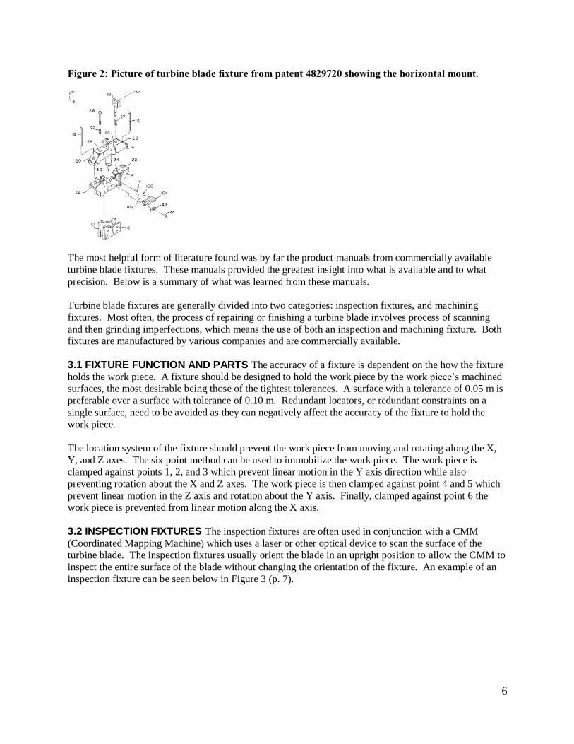
Patent number 4829720 by Cavalieri describes a horizontally positioned turbine blade fixture used for machining defects on the surface of the turbine blade. The fixture presented in this patent, Figure 2 (p. 6),
is not precise enough to use for inspection, but does show how a turbine blade can be mounted using only
a small portion of its base and still be held rigidly against grinding forces.
6
Figure 2: Picture of turbine blade fixture from patent 4829720 showing the horizontal mount.
The most helpful form of literature found was by far the product manuals from commercially available
turbine blade fixtures. These manuals provided the greatest insight into what is available and to what
precision. Below is a summary of what was learned from these manuals.
Turbine blade fixtures are generally divided into two categories: inspection fixtures, and machining
fixtures. Most often, the process of repairing or finishing a turbine blade involves process of scanning
and then grinding imperfections, which means the use of both an inspection and machining fixture. Both fixtures are manufactured by various companies and are commercially available.
3.1 FIXTURE FUNCTION AND PARTS The accuracy of a fixture is dependent on the how the fixture
holds the work piece. A fixture should be designed to hold the work piece by the work piece’s machined surfaces, the most desirable being those of the tightest tolerances. A surface with a tolerance of 0.05 m is
preferable over a surface with tolerance of 0.10 m. Redundant locators, or redundant constraints on a
single surface, need to be avoided as they can negatively affect the accuracy of the fixture to hold the
work piece.
The location system of the fixture should prevent the work piece from moving and rotating along the X,
Y, and Z axes. The six point method can be used to immobilize the work piece. The work piece is clamped against points 1, 2, and 3 which prevent linear motion in the Y axis direction while also
preventing rotation about the X and Z axes. The work piece is then clamped against point 4 and 5 which
prevent linear motion in the Z axis and rotation about the Y axis. Finally, clamped against point 6 the work piece is prevented from linear motion along the X axis.
3.2 INSPECTION FIXTURES The inspection fixtures are often used in conjunction with a CMM
(Coordinated Mapping Machine) which uses a laser or other optical device to scan the surface of the turbine blade. The inspection fixtures usually orient the blade in an upright position to allow the CMM to
inspect the entire surface of the blade without changing the orientation of the fixture. An example of an
inspection fixture can be seen below in Figure 3 (p. 7).

7
Figure 3: Turbine blade inspection fixture made by Flow Systems. Picture taken from
www.flowsystemsinc.com.
The standard insertion of the blade into the fixture is by positioning the machined pins on the side of the
blade into rigid slides which guide the blade into a mechanical stop. The pins on the sides of the blades
are used to guide the blade into the plenum on the turbine assembly and are very precisely machined. The rigid slides are usually made of carbide. The blade is then clamped down, either automatically or
manually. In some situations pneumatics and hydraulics have been used to aide clamping mechanisms.
Clamping forces on the turbine blade in inspection fixtures do not have to be as great as the clamping forces in machining fixtures. The standard of tolerances for inspection fixtures is roughly 2/10 of the
tolerance of the machined fixture parts.
Companies that manufacture and sell inspection fixtures include:
AeroCad Design Inc. - 4012 W. Kitty Hawk Chandler, AZ 85226 USA
Flow Systems Inc. – 220 Bunyan Ave. Berthoud, CO 80513 USA
NEXTEC Technologies 2001 Ltd. Carmel Business Park, Haetgar St., Tirat Hacarmel 39120
Israel
3.3 GRINDING Fixtures used to hold turbine blades during grinding serve multiple purposes. They can
be used to scan parts of the turbine blade, final machining of the blade, but more generally they are used
for grinding away imperfections on the surface of the blade. Fixtures used for grinding need to hold the
turbine blade rigidly as a grinding force is applied. This force tends to be around 5 lbs. This can generate a considerable moment on the turbine blade, therefore grinding fixtures usually hold the blade
horizontally, or parallel to the base surface. An example of this type of fixture can be seen in Figure 4
(p. 8).

8
Figure 4: AeroCad Design Inc. example of machining fixture for turbine blade with horizontal
mount. Picture taken from www.aerocaddesign.com.
The blade is similarly inserted into the grinding fixture as it was in the inspection fixture; by aligning the machined surfaces of the turbine blade with precision machined carbide surfaces. Grinding fixtures place
a considerably larger clamping force on the blade than do the inspection fixtures. The clamping force can
be manually or automatically applied to the blade. Strain gauges or other gauges to determine the alignment and force applied to the blade are typically used to ensure uniformity in force clamping force
applied to the blade. These gauges can also be used to signal that the blade is in correct position to be
machined. Supports for the blade in various positions along its chord length can also be implemented to
keep the blade more rigid. Again, the precision grinding of the fixture’s parts will determine the precision and repeatability of the fixture’s hold on the turbine blade. As is with inspection fixtures, the industry
standard for grinding the fixture is roughly 2/10 the tolerance of the machined fixture parts.
Companies that manufacture and sell inspection fixtures include:
AeroCad Design Inc. - 4012 W. Kitty Hawk Chandler, AZ 85226 USA
3.4 COMMERICIALLY AVAILABLE FIXTURES 3.4.1 WIZBLADE BY NEXTEC The Wizblade is a system of turbine blade inspection for both machine finished and unfinished turbine blades. The Wizblade is accompanied by the Wizprobe, which is the non-
contact laser used for scanning the surface of the turbine blade. The Wizprobe is self-calibrating and can
adapt to changing conditions during scanning. The Wizblade’s software automatically calibrates to the
position of the turbine blade using the Wizprobe. The Wizprobe is attached to a 4-axis motion controller. The Wizblade’s platform can come with a variety of fixtures to suit most turbine blades. The Wizblade’s
fixture is for inspection only, not machining.
Performance (taken from www.nextec-wiz.com):
Automatic alignment time: 50 seconds
Typical cross-section scanning time (both sides): 8 seconds
Platform accuracy: (3+3.5L) microns (L = length in meters)
Total machine accuracy: 14 microns
Total machine repeatability: 4 microns
Data capture rate: 50 points per second
3.4.2 AEROCAD DESIGN FIXTURES AeroCad Design Inc. develops custom built turbine blade fixtures for either inspection or machining. Their fixtures are built with high precision and can hold a tolerance of
2/10 of the tolerance of the machining of the actual fixture. The fixtures are made of tool steel and the
pinning surfaces are made of carbide to give a very repeatable and exact fit. These fixtures are not

9
automatically clamping, but do provide outstanding support of the blade. Displacement gauges and strain
gauges can be incorporated in AeroCad fixtures to ensure repeatable positioning of the turbine blade. 3.4.3 MULTIPURPOSE FIXTURES Unfortunately, no literature or products that we have researched are
used for both grinding and inspecting, it is seems to be that there is one fixture used for one, and one for
the other. Therefore, we are led to believe that our project is a new idea that either has not been done, or has not been largely researched. Therefore, we will be using components from both of these fixture types
that we have researched into our final design.
4. PROJECT REQUIREMENTS/ENGINEERING SPECIFICATIONS After meeting with our project sponsor we were able to break the project down so that we could assess the
customer needs efficiently. We determined that the project constraints were based on seven customer
needs: 1. The fixture must hold the prescribed gas turbine blade.
2. The fixture must have high precision, in which the loading of blades cannot vary by an absolute
magnitude of +/- 20 microns. 3. This precision must be repeatable over time.
4. The fixture must be easy to use.
5. The cost must remain under $400.
6. The fixture must not obstruct any laser or grinding operations. 7. The fixture must be lightweight (under 7 kg).
Table 1: Technical Specifications used for engineering analysis and their descriptions.
Technical Specification Description
Mass How heavy the fixture is Material What the fixture is made of Geometry The shape of the fixture Withstanding Tolerances How accurate the fixture will be in positioning the blade Fit Surroundings Must fit to the bolt pattern on the bolt plate and hold the
blade Thermal Expansion Expansion due to temperature change No Plastic Deformation Permanently changing the blade or fixture Withstanding Grinding Forces Rigidity of the blade while grinding occurs Quality Control Robustness and durability of the fixture Loading Time How long it takes to load and unload the blade Safety and Transport How safe the fixture is to use and easiness of
transportation Kinematics Moving parts in the fixture Signals Any sort of light or buzzer warnings
From these customer needs, we needed to determine the engineering specifications of this fixture. These specifications were used in the Quality Function Deployment (QFD) analysis of the project. This analysis
takes the technical specifications and compares them with the customer needs in order to see how they
compare with one another. This allowed us to easily come up with a ranking of importance of the
technical specifications which is shown on our QFD diagram (Figure 5, p. 10). The QFD also allowed us to come up with relations between technical specifications.

10
Figure 5: Quality Function Deployment analysis spreadsheet
The QFD also took into account the competitor’s products, so that we could see the strengths and
weaknesses of the fixture. The strengths and weaknesses were compared only to the customer needs, since they will be the ones evaluating the final product. There were three competitors that were taken into
consideration, and were chosen because of relevance to our project and the quality of the product. The
first competitor, represented by the letter A in the QFD, is a vice that is used in the lab that we are trying to directly replace. This is very easy to install, but can be inaccurate and transforms need to be run every
time a new blade is loaded. The next competitor represented by B, is the current system that General
Electric uses, which is mentioned earlier in this report. The multi-step process that the blade goes through is very inefficient, however it is very accurate. The third, competitor C, is the Nextec Wizblade. The
advantages and disadvantages of each device are rated in the QFD in comparison with our customer
needs.

11
5. CONCEPT GENERATION
5.1 FUNCTIONAL DECOMPOSITION In order to better display and organize our conceptual
challenges and their component, we developed a thorough functional decomposition. The functional
decomposition is segmented into two layers. The first layer, Figure 6, describes the inputs and outputs of the turbine blade fixture. The second layer, Figure 7 (p. 12), describes the path which the inputs will take
in conjunction with certain functions to produce the desired output.
The first layer shows the inputs energy, blade, bolt pattern, and signal. Each of these represents a known
input to the system, a combination of which are transformed into the corresponding outputs. The outputs
included a force in the x, y, and z directions on the blade, the orientation of the blade, and an output
signal. It is important to note that this decomposition showed that positioning the blade and restraining the blade were two separate outputs. These outputs must be addressed individually; however, a singular
function can accomplish more than one output.
Figure 6: First layer of the functional decomposition showing the inputs and outputs of the turbine
blade fixture.
F unctional Decompos ition
T urbine B lade F ixture
E nergy
B lade
B olt P attern
S ignal
F orce (x,y,z)
Orientation of B lade
S ignal
The purpose of the second layer of the functional decomposition was to conceptually detail the paths and
interactions of the inputs until they produce the desired output. The second layer is shown in Figure 7 (p.
12). On the left are the inputs derived from the first layer, and on the right are the outputs also derived from the first layer. The paths of the inputs are shown with the arrows, accompanied by a small
description along the path. The white boxes represent a task or transformation of their inputs, relaying an
output. In this way, the individual functions of the turbine fixture are displayed in a visual manner. This allowed us to develop features of the fixture to accomplish the individual tasks in order to complete the
overall task of positioning the blade with high repeatability firmly while withstanding grinding forces.

12
Figure 7: Second layer of functional decomposition showing the individual paths the inputs, left
side, will take as well as their tasks to achieve the outputs, right side.
B lade
E nergy
S ignal
B olt P attern
P os ition B ladeIn F ixture
C ontact
Move C lamping F aces
S ignal
F orce on B lade
F inal Orientation
L ocking
F as ten to Table
Ma
nu
al
Hydraulic, electrical,
mechanical
Hydraulic, electrical, mechanical
Ma
nu
al
The inputs and outputs have already been described by the above paragraph concerning the first layer of
the decomposition. The important second layer functions are positioning the blade in the fixture,
contacting the blade, moving the clamping faces, locking the blade into place, and fastening the fixture to the table. The diagram can be read as follows:
1. The fixture is fastened to the table via the bolt pattern
2. The blade is positioned in the fixture using manual energy 3. Energy, in the form of hydraulic, electrical, or manual, is used to move the clamping
faces
4. The blade comes into contact with the clamping faces. The input signal to the contact faces changes
5. Energy is used to lock the clamping faces and blade into place
a. An output signal is sent to either a feedback loop, controller, or interface
b. A force is placed on the blade in the x, y, and z directions to hold it in place c. The blade is in the final orientation
This is a loose description of the diagram, but it highlights the main components that must be accomplished by the fixture. The main use of the functional decomposition was to add structure and
guidance to our concept generation.
5.2 BRAINSTORMING The main portion of our concept generation can be divided into three
categories: brainstorming, a morphological chart, and consensus. After concluding the functional
decomposition, the individual functions to be satisfied became the structure of our brainstorming session.
For our brainstorming session we thought of concepts to satisfy the functions of loading the blade into position, signals (I/O), initial contact faces, and locking mechanisms. Approximately twenty minutes was
spent on each category, the results can be seen in Table 2 (p. 13).

13
Table 2: Results of brainstorming based on the functions described in the functional decomposition.
After brainstorming, the most feasible concepts in each category were chosen as the basis of a morphological chart. The morphological chart, Figure 8 (p. 14), was used as a method of forming fully-
functional concepts by simply means of “brute force”. After generating “brute force” concepts, we were
able to visualize which concepts would work and which ones would not, and to be more selective in our design selection process.
The morphological chart represents combinations of means to satisfy the overall function of the fixture. It is important to note that none of the means on the chart are mutually exclusive, meaning that any and all
means can be incorporated into a single concept. The consequence of using too many means of
constraining the blade is redundancy, which can lead to a decrease in the accuracy of the fixture. Also,
none of these means limit the geometry, accuracy, precision, or repeatability of the final fixture. Since this fixture is being designed for use in a specific laboratory, the production means of each of these
features on the final design are moot at this point. The morphological chart and brainstorming session did
not include the subfunction of fastening the fixture to the rotary table; bolts will be used for that operation. Some of the means on the morphological chart might not necessarily be used in a prototype,
due to cost issues. However, they were considered as they could be part of a final design in which the
economics of producing multiple fixtures would allow for more expensive means, such as the linear variable displacement transducers (LVDT).
Loading
Guide for the pins on the blade
Collets for the pins
Protrusions on the top and sides
Latch like the plenum
Spring-loaded sides
Magnets
Initial contact faces
V-blocks/wedge sides
V-block pins
Latching arm on hooks
Wedge entire bottom
Profile fit
Pins
Inverted cone for guide pins
Pin bed
Locking
Threads for pinning collets
Differentials for loads
Torque wrench
Eccentrically loaded lever
Lock ratchet
Pneumatics
Linkage
Springs
Plastically deforming surface
Chucks for pins
Signals
Force transducer
Strain gauge
Laser limit switch
Locking faces completes a
circuit
Visual
LVDT

14
Figure 8: Morphological chart formed from brainstorming means to satisfy the subfunctions of the
turbine blade fixture.
We utilized the morphological chart to create almost twenty minor concepts that could complete the
subfunctions and, ultimately, the overall function of the turbine blade fixture. Each team member then used these minor functions to create their own individual concept. These concepts utilized each of the
team member’s creativity, which would later translate into the alpha design. Each of these concepts can
be seen in Appendix F, Designs 1, 2, 3, 4, 5, 6, 7, 8, and 9 and Table F.1. The CAD representations of these concepts were constructed in Unigraphics NX 5.0. Each of these initial concepts was designed to
complete the task of the final fixture and all of its subfunctions.
6. CONCEPT SELECTION Initial concepts were compared by determining how well each concept met each design requirement.
Each requirement was given a weighting from one to three, and this scoring method can be seen in a Pugh chart, Table 3 (p.15). The linkage clamp concept was chosen as a datum due to its simplicity, and given a
score of zero. All other concepts were compared against the datum and given a score from -3 to 3 for
each design requirement.

15
Table 3: Pugh chart comparing initial concepts based on meeting design criteria.
Design Criteria Wt. Linkage
Clamp
Protrusion
Channel
Bottom Profile
Wedge
Rotating
Frame
Pin Holes α-Design
Manufacturability 1
D A
T
U M
-2 -2 0 0 0
High repeatability 3 1 0 1 0 2
Easy to use 2 0 1 -1 1 -1
Cost 1 -1 -1 -3 0 -3
Can't obstruct robot 2 -1 0 0 0 0
Lightweight 1 0 0 0 0 0
CG of blade over turntable center 2 0 0 0 0 0
Withstand grinding
forces 3 2 0 2 -2 2
Load time 2 -1 2 -2 1 -2
Accurate placement 2 0 0 0 1 1
0 2 3 0 0 5
6.1 LINKAGE CLAMP The linkage clamp design was chosen as the Pugh chart datum, and when
comparing to other designs, there are a few advantages and disadvantages of the design. Its advantages are ease of manufacturability, cost, and loading time. The main disadvantage of the design is the potential
for low ability to withstand grinding forces and slightly reduced repeatability since all clamping surfaces
are close to the blade’s base. 6.2 PROTRUSION CHANNEL The protrusion channel design’s overall advantages include high
repeatability and high ability to withstand grinding forces. These advantages are due to the incorporation
of profile clamping faces which accurately mesh with the blade, and the fact that the blade is held far from the base. Disadvantages include the cost and manufacturing issues associated with creating
extremely precise profiled clamping faces.
6.3 BOTTOM PROFILE WEDGE The bottom profile wedge has similar advantages and disadvantages due to the use of profiled clamping faces. The main advantage is high repeatability and disadvantages are
again cost and manufacturability. Since this design holds the blade closer to the base, it is not as able to
withstand the forces due to grinding. However, advantages to this design include quick loading time and
ease of use. 6.4 ROTATING FRAME The rotating frame design’s main feature is being able to tightly hold the blade
in place while holding it close to the base, to ensure minimal laser/grinder occlusion. However, a
potentially slow load time and high cost are disadvantages due to the complexity of the design. The individual parts of the concept, however, would not be difficult to manufacture.
6.5 PIN HOLES The pin hole concept has the advantage of design simplicity. This results in a fixture
that is easy and inexpensive to manufacture. It is also easy to use and has a short loading time. However, its main disadvantage concerns its potential inability to withstand grinding forces.
6.6 ALPHA DESIGN GENERATION Our Pugh chart analysis gave us scores for each concept which
were very close to each other. Because of this small differentiation, we designed our alpha concept to be

16
a combination of some of the initial concepts. Since only some aspects of each design work together, it
was not feasible to produce a true combination of all five designs. Our alpha design is built off the rotating frame concept, but a base wedge has been added to improve repeatability and accurate placement.
The design was incorporated into the Pugh chart (Table 3, p.15) to verify the fact that it is indeed the best
concept we have generated. It scored a total of five points, which is the highest scoring of the designs.
Figure 9: Complete α-Design
From here it will be discussed how and what feature in the concept ensures the turbine blade is
constrained in each of the axes of motion. The V-blocks were chosen to support the pins located at the base of the blade. This constrains any displacements in the negative z-axis (downwards) as well as
rotation about the y-and z-axis. The V-blocks also allow for quick installation and removal of the blade
since there are no moving components. A CAD model of the V-blocks is provided in Figure 10.
Figure 10: CAD model of V-blocks

17
Tapered beams, provided in Figure 11, are utilized to constrain the blade from rotation about the x-axis,
whereas the pins on V-blocks would have acted as a pin joint. Furthermore, the tapered beams constrain any displacements in the positive or negative y-axis. In addition, since the tapered beams are intended to
match the profile of the blade base, the purpose of this feature also lends to ease of installation and
removal by the user.
Figure 11: CAD model of tapered beams
An adjustable pin is located in line with the V-blocks which are intended to contact the pin feature. By
contacting and apply a force the blade is now constrain from displacement in both the positive and
negative x-axis.
Figure 12: CAD model of adjustment pin location
Adjustment Pin

18
The intent of this design is to have all of the previously mentioned components be initial contact surfaces.
Once this condition is met the user can release the blade and initialize an input signal which would activate the rotating frame feature provided in Figure 13 (p.18). This rotating frame component contacts
the blade on the bracket features located at the mid-section of the base of the blade (the bracket features
will be much more evident once a CAD model of the turbine blade is available) and these frames
constrain motion in the positive z axis. The brackets also have a slight curvature which is duplicated on the contacting face of the rotating frame. Once a prescribed amount of force is applied, via the rotating
frame, the turbine blade is now fully constrained and ready for any laser inspection or modification
processes that are necessary.
Figure 13: CAD model of rotating frames
Once the blade is ready for removal a signal is input by the user to then release the applied force acting on
the blade by retracting the rotating frames and adjustable pin. The user can then remove the blade and the
cycle can re-start.
7. CONCEPT DESCRIPTION In finalizing our alpha design, key measurements were taken of blade and the fixture was scaled accordingly. The rotating frames were simplified and directly hinged using clevis pins to another frame
which moves vertically along the outside of the fixture. This vertical frame applies the clamping force to
the turbine blade through the use of toggle clamps which move the frame in relation to the fixture base
plate.
Rotating Frame

19
Figure 14: Revised rotating clamps (Top) attach to the vertical clamp (Bottom).
The tapered beams have been omitted from design, and to fix the blade in this direction, the rotating frames now have spring plungers. These spring plungers were screwed into the rotating frames,
contacting the hooks on the blade and properly positioning the blade. The V-blocks (Figure 10, p. 16)
were chosen to support the pins located at the base of the blade. This constrains any displacements in the negative z-axis (downwards) as well as rotation about the y-and z-axis. Also, to fix the blade between the
V-blocks a knob has been fabricated to attach to a spring plunger and contact the blade and the end of one
of the pins (Figure 29, p. 36). By contacting and apply a force the blade is now constrain from
displacement in both the positive and negative x-axis. An in-depth exploded view is seen in Figure 15 (p. 20) and a detailed design description is to be found in Section 9 (p. 25).
20
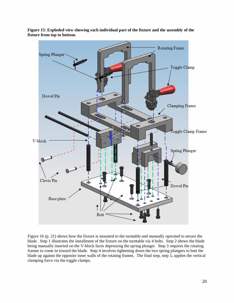
Figure 15: Exploded view showing each individual part of the fixture and the assembly of the
fixture from top to bottom.
Figure 16 (p. 21) shows how the fixture is mounted to the turntable and manually operated to secure the
blade. Step 1 illustrates the installment of the fixture on the turntable via 4 bolts. Step 2 shows the blade
being manually inserted on the V-block faces depressing the spring plunger. Step 3 requires the rotating frames to come in toward the blade. Step 4 involves tightening down the two spring plungers to butt the
blade up against the opposite inner walls of the rotating frames. The final step, step 5, applies the vertical
clamping force via the toggle clamps.

21
Figure 16: Conceptual use of the fixture bolting to turntable and securing blade.
8. PARAMETER ANALYSIS 8.1 FORCE ANALYSIS When clamping the turbine blade into place, forces are exerted in 3 locations.
The clamping frame is pulled down toward the base on each end. These two equal forces can be adjusted
after assembly of the fixture. The third force is the adjustment pin acting on the blade, which has a
magnitude between one and five pounds. This force acts through a spring-loaded pin. With these static forces acting on the fixture and blade during inspection, proper analyses must be done to ensure that the
blade and fixture do not deform.
The grinding force, which will be 5 lbs at maximum, creates a moment on the blade. This moment will
have the highest magnitude when the grinding wheel is contacting the tip of the blade. With this added
moment the fixture must be able to hold the turbine blade correctly. A static force analysis summing all
forces and moments to zero, found the grinding force to exert a maximum of 12.5 lbs of force upward and 13.2 lbs laterally on each rotating clamp. All resulting forces can be seen in Figure 17 (p. 22). To ensure
the blade remains fixed under grinding operations, each clamp will provide 15 lbs of downward force.
This clamping force is designed to be adjustable, and will be calibrated when the fixture is assembled. A large safety factor is unnecessary because even if opposing force overcomes the pre-load force exerted by
the clamps, the clamps will still react with enough force since they are locked into place.
1
2
3
4
5

22
Figure 17: Resulting forces due to grinding loads
a) Lateral grinding load on blade b) Axial grinding load on blade
c) Lateral grinding load on rotating clamp
5 lbs grinding
force
13.2
lbs
8.2 lbs
6.6 lbs
3.3 lbs 3.3 lbs
7.4 lbs 7.4 lbs
5 lbs
12.5 lbs
12.5 lbs
5 lbs grinding
force

23
The resulting force on the V-blocks will be the sum of the downward force exerted by the clamps and the
grinding force, which will be a maximum of 27.5 lbs of force on each V-block. To ensure proper support of this load on a small surface area, steel has been chosen over aluminum as the V-block material.
Maximum lateral loads due to grinding will be 6.6 lbs on each rotating clamp, 8.2 lbs on each V-block,
and 5 lbs on the V-block pin. The force on the rotating clamp will be passed on through the pins connecting the rotating clamps to the vertical clamp. These forces will be 7.4 lbs vertical and 3.3 lbs
lateral on each pin. Lateral loads on the V-block will result in matching upward loads on the turbine
blade. This is to be of concern since the blade must remain properly seated in the V-blocks. However, since the clamping force is 25 lbs, 8 lbs of upward force will not be an issue. The V-block pin, which is
spring loaded, is rated for 5 lbs at maximum spring deflection. While the grinder may exert 5 lbs in this
direction, the pin will require far less than 5 lbs of force acting on the turbine blade due to large frictional forces at the V-blocks and rotating clamps.
To further ensure that our fixture can withstand the aforementioned forces, a simplified FEA simulation
was ran. This analysis only included the top half of the design: the vertical clamp and rotating clamps, including the pins which connect them together. 250 N of downward force was applied to each end of the
fixture, where the toggle clamps would be mounted. The base of the blade is fixed and the vertical clamp
is constrained to move only vertically at the four dowel pin locations. Figure 18 shows where the highest stresses occur (15 MPa on the fixture, 30 MPa on the blade). Since these stresses are well below the yield
stresses of the given material, we are confident that our fixture and turbine blade will resist yielding.
Figure 18: FEA analysis showing stress of the top half of fixture and bottom half of blade.
15 MPa
30 MPa

24
While more rigorous FEA simulations could be ran, not only does time not allow for this, but we feel a
full analysis is unnecessary. Side loads due to grinding and tilting the fixture are low and we are confident these forces will not cause any yielding of our fixture. Any micron-level deflections due to
these forces are not important since these deflections will only be seen during grinding and not during
inspection. However, if the V-block faces, which are the most critical parts from a repeatability
standpoint, deflect on the micron level, this could hinder repeatability. This is of concern since these faces bear a lot of the vertical load and have small surface areas. To ensure the V-block faces will
withstand these forces without deflection, we performed another FEA simulation (Figure 19).
Figure 19: FEA simulation showing deformation of the V-block face.
In this simulation we imposed a force of 250 N downward on the V-block faces and fixed the faces
contacting the base plate and the dowel pins. We found the maximum deflection to be on the tenth of a micron scale, which ensures that the V-blocks will withstand all forces and repeatability will not be
compromised.
8.2 AXIS OF ROTATION The mass of the fixture is between 4 and 5 kg, with its exact weight currently
unknown due to the use of outside parts. For the lab prototype, mass and center of gravity is not critical,
however when the fixture is designed for the factory, the CG can be altered by counter weighting. If the
CG is aligned with the robotic axis of rotation, a small enough moment will be acting on the rotating axis.
We have ensured that the clamping force is high enough to keep the blade fixed in any orientation.
8.3 THERMAL EXPANSION The most critical parts for ensuring repeatability are the V-block faces,
and changes in temperatures could affect the overall position of a turbine blade in the fixture. The largest
dimension on the V-block is 60mm, and when undergoing a 10C temperature change, this dimension could change by 7 microns (Eq. 1). In the lab setting, a 10C temperature swing is unlikely, and even so, 7
microns falls within the 20 micron repeatability target.
∆𝐿
𝐿=∝ ∆𝑇 𝐸𝑞. 1

25
8.4 LOADING TIME Loading the fixture requires four steps: Initial positioning of the blade, tightening
the knobs on the clamps, tightening the adjustment pin at the V-blocks, and finally clamping down the
blade using the toggle clamps. It is reasonable to allow 5 seconds for each step, resulting in 20 seconds of total load time of the fixture which meets our requirement.
8.5 OTHER PARAMETERS In addition to technical parameters, other aspects were taken into
consideration such as material selection, assembly, environmental sustainability, safety, and manufacturing. Higher detail regarding our design in regard to these topics is in Appendix C.
8.5.1 DESIGN FOR MATERIALS When choosing material for the V-block faces, it is important to choose a material that is hard yet still able to machine. The top choice for this component is Nickel-Cobalt-
Chromium Alloy, AEREX 350. For the rest of the components, it is important to choose a material that is
lightweight, low in cost, and able to machine, but it still must not deform from the clamping loads
imposed on the fixture. This leads to the use of Aluminum Alloy 7055 for the other major components of the fixture.
8.5.2 DESIGN FOR ASSEMBLY In order to improve efficiency in the assembly process, we found that the original assembly time of 5 minutes could be cut down by 40%, resulting in a 3 minute assembly
process. This was done by reducing the number of parts in our design. However, since our fixture is to
be machined, this reduction in parts results in an increase of material usage and machining time. This is a tough balancing act but it was found that some of the assembly changes could be made without adversely
affecting the manufacturability of the fixture.
8.5.3 DESIGN FOR ENVIRONMENTAL SUSTAINABILITY When considering environmental sustainability, our fixture has a relatively low impact on the environment. The bulk of its impact (90%) is
due to drain on resources in the form of energy required in creating the materials. The remainder of the
environmental impact is due to waste in the material creation and disposal processes. Our design is generally environmentally friendly due to its manual energy input, low mass, and recyclability. With the
exception of the V-block faces and dowel pins, the fixture is made of recyclable aluminum alloys.
8.5.4 DESIGN FOR SAFETY Since the only energy input for our fixture is manual user-applied forces, risks to the operator are minimal. The locking force required to lock down the toggle clamps lets the
operator know that the blade is adequately held by the fixture. This prevents the risk of the grinding robot
coming into contact with a poorly held turbine blade. Eye protection is recommended for the user in case the blade is incorrectly loaded into the fixture which could result in flying small parts. Warning signs
should also be posted nearby so passers-by are informed that a laser may be in use.
8.5.5 DESIGN FOR MANUFACTURING Machining has been chosen as a manufacturing process because
of the small amount of fixtures being produced (100-500). A CNC mill can achieve tolerances tight
enough to meet our repeatability requirements. Our materials have all been chosen with how easy they
are to machine in mind, and the hardest of materials we have chosen require minimal material to be machined away.
9. FINAL DESIGN DESCRIPTION The final design of the fixture to house the turbine blade for both machining and inspection purposes derived from the refinement of the alpha design and input from material selection and individual part
makeup. The final design stresses the importance of the six-point method to constrain the turbine blade
while providing a securing force during machining of the blade. There are two main final designs: one designed for the ERC lab at the University of Michigan Ann Arbor, and one designed for production used

26
in conjunction with Western Robotics. The design for the ERC lab has priority over the design for
Western Robotics. There are a few differences in the engineering specifications for both designs, but they are relatively minor and leave the main mechanisms and dimensions of the fixture unchanged. The
working prototype will ultimately server as the final design for the ERC lab. Therefore, the materials,
dimensions, and specifications that are described in the final design for the ERC lab will coincide with the
materials, dimensions, and specifications of the working prototype. The completed fixture in operation is pictured in Figure 20.
Figure 20: Completed fixture mounted on turntable
9.1 OVERVIEW A CAD representation of the final design of the fixture housing the turbine blade can be seen in Figure 21
(p. 27). The fixture holds the blade in a vertical position with the base of the blade at the bottom. The fixture does not obstruct the scanning laser or the grinding robot from accessing the important faces of the
blade; the sides of the blade base are not targeted during the inspection and grinding phases. The ERC lab
has a different AEROTECH turntable than the Western Robotics turntable. The bolt holes on the base plate of the ERC lab’s final design are designed to fit onto the turntable in the ERC lab.

27
Figure 21: Isometric view of final design of turbine blade fixture housing CAD representation of the
blade. The blade is shown in blue to differentiate it from the fixture.
Figure 15 (p. 20) shows an exploded view of all the components and fasteners that compose the fixture.
The exploded view does not show the blade. The exploded view also shows the names and quantities of
the parts. Figure 15 also represents the order of assembly, from top to bottom. The final design is assembled in this manner in order to assure that the dowel pins will effectively and precisely position
each individual part before it is fastened by bolts. An itemized bill of materials can be seen in Appendix
D. The following section will describe major component in detail and its function. In addition, a list of
the major components is as shown:
(1) Base plate
(1) V-block base
(1) Threaded V-block base
(2) V-block faces
(1) Clamping frame
(2) Rotating frames
(1) Spring plunger
(2) Toggle clamps
28
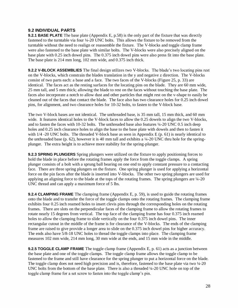
9.2 INDIVIDUAL PARTS 9.2.1 BASE PLATE The base plate (Appendix E, p.58) is the only part of the fixture that was directly fastened to the turntable via four ¼-20 UNC bolts. This allows the fixture to be removed from the
turntable without the need to realign or reassemble the fixture. The V-blocks and toggle clamp frame
were also fastened to the base plate with similar bolts. The V-blocks were also precisely aligned on the
base plate with 0.25 inch dowel pins. The 0.375 inch dowel pins were also press fit into the base plate. The base plate is 214 mm long, 102 mm wide, and 0.375 inch thick.
9.2.2 V-BLOCK ASSEMBLIES The final design utilizes two V-blocks. The blade’s two locating pins rest
on the V-blocks, which constrain the blades translation in the y and negative z direction. The V-blocks
consist of two parts each: a base and a face. The two faces of the V-blocks (Figure 25, p. 33) are
identical. The faces act as the resting surfaces for the locating pins on the blade. They are 60 mm wide, 25 mm tall, and 5 mm thick; allowing the blade to rest on the faces without touching the base plate. The
faces also incorporate a notch to allow dust and other particles that might rest on the v-shape to easily be
cleaned out of the faces that contact the blade. The face also has two clearance holes for 0.25 inch dowel pins, for alignment, and two clearance holes for 10-32 bolts, to fasten to the V-block base.
The two V-block bases are not identical. The unthreaded base, is 35 mm tall, 15 mm thick, and 60 mm wide. It features identical holes to the V-block faces to allow the 0.25 dowels to align the two V-blocks,
and to fasten the faces with 10-32 bolts. The unthreaded base also features ¼-20 UNC 0.5 inch deep
holes and 0.25 inch clearance holes to align the base to the base plate with dowels and then to fasten it
with 1/4 -20 UNC bolts. The threaded V-block base as seen in Appendix E (p. 61) is nearly identical to the unthreaded base (p. 62), however it is 40 mm tall and exhibits a ¼-20 UNC thru hole for the spring-
plunger. The extra height is to achieve more stability for the spring-plunger.
9.2.3 SPRING PLUNGERS Spring plungers were utilized on the fixture to apply positioning forces to
hold the blade in place before the rotating frames apply the force from the toggle clamps. A spring
plunger consists of a bolt with a sprung ball bearing on one end to apply constant pressure to a contacting face. There are three spring plungers on the fixture. One spring plunger is used for applying a horizontal
force on the pin faces after the blade is inserted into V-blocks. The other two spring plungers are used for
applying an aligning force to the blade at the tops of the rotating frames. The spring plungers are ¼-20 UNC thread and can apply a maximum force of 5 lbs.
9.2.4 CLAMPING FRAME The clamping frame (Appendix E, p. 59), is used to guide the rotating frames onto the blade and to transfer the force of the toggle clamps onto the rotating frames. The clamping frame
exhibits four 0.25 inch reamed holes to insert clevis pins through the corresponding holes on the rotating
frames. There are slots on the perpendicular faces of the clamping frame to allow the rotating frames to rotate nearly 15 degrees from vertical. The top face of the clamping frame has four 0.375 inch reamed
holes to allow the clamping frame to slide vertically on the four 0.375 inch dowel pins. The inner
rectangular cutout in the middle of the frame is for clearance of the V-blocks. The ends of the clamping
frame are raised to give provide a longer area to slide on the 0.375 inch dowel pins for higher accuracy. The ends also have 5/8-18 UNC holes to thread the toggle clamps into place. The clamping frame
measures 102 mm wide, 214 mm long, 30 mm wide at the ends, and 15 mm wide in the middle.
9.2.5 TOGGLE CLAMP FRAME The toggle clamp frame (Appendix E, p. 61) acts as a junction between
the base plate and one of the toggle clamps. The toggle clamp frame allows the toggle clamp to be
fastened to the frame and still have clearance for the spring plunger to put a horizontal force on the blade. The toggle clamp does not need high precision and is, therefore, fastened to the base plate via two ¼-20
UNC bolts from the bottom of the base plate. There is also a threaded ¼-20 UNC hole on top of the
toggle clamp frame for a set screw to fasten into the toggle clamp’s pin.

29
9.2.6 ROTATING FRAMES The rotating frames (Appedix E, p. 60) transfer the clamping force from the
clamping frame to the turbine blade itself. The rotating frames act as the mechanism that holds the blade in place during inspection and grinding. The top of the rotating frame is shaped to contact the hook-like
protrusions on the upper sides of the blade and also to constrain the blade from dramatically rotating on
the horizontal axis. At the top of the rotating frame is a ¼-20 UNC threaded hole for a spring-plunger to
apply an additional aligning force on the blade. The bottom of the rotating frame has a 0.25 inch hole for a clevis pin that fastens the frame to the clamping frame. The rotating frames are sized 87 mm tall, 92
mm wide, and 0.5 inch thick.
9.2.7 TOGGLE CLAMPS The fixture utilizes two toggle clamps. The clamps were bought as an
assembled unit from McMaster-Carr. The toggle clamps have two locking positions: extended and
retracted. The pin in the center of the toggle clamp has a stroke of 0.75 inches. The pin also has a ¼-20 UNC threaded hole on the bottom side for fastening to the base plate via a bolt. The base of the toggle
clamp also has 5/8-18 UNC threads to fasten to the base plate. As mentioned earlier, the toggle clamp’s
pin will be fastened to the base plate and remain fixed such that the force of the extension and retraction of the clamp will be transferred into the motion of the clamping frame. The toggle clamp also has a nut
on the 5/8-18 UNC threads in order to change the stroke length, ultimately changing the clamping force.
The maximum clamping force available is 200 lbs.
9.2.8 DOWEL PINS Dowel pins of various sizes are used to align the individual components of the fixture
to the base plate. They are made of stainless steel.
For detailed drawings of each part see Appendix E.
9.3 ASSEMBLY
1. Insert 0.25 inch diameter 0.75 inch length dowel pins into base plate holes to align V-blocks. 2. Insert V-blocks onto dowel pins and fasten to base plate using ¼-20 UNC bolts from the bottom
of base plate.
3. Insert 0.25 inch diameter 4 inch length dowel pins horizontally into V-blocks while also aligning
V-block faces to 4 inch dowel pins. 4. Fasten V-block faces to V-block bases using 10-32 bolts.
5. Fasten rotating frame to top of base plate with ¼-20 UNC bolts from the bottom of base plate.
6. Insert 0.375 inch diameter 2.5 length dowel pins to four corner holes on top of base plate. 7. Slide clamping frame onto 0.375 diameter dowel pins.
8. Thread 5/8-18 UNC threaded toggle clamps onto clamping frame.
9. Thread ¼-20 UNC bolt into toggle clamp pin from bottom of base plate.
10. Thread ¼-20 UNC set screw from bottom of toggle clamp frame into toggle clamp pin. 11. Attach rotating frames to clamping frame using clevis pins.
12. Thread ¼-20 UNC spring plunger into threaded V-block base.
13. Thread ¼-20 UNC spring plungers into top of rotating frames. 14. Insert four ¼-20 UNC bolts to top of base plate to fasten to turntable.
9.4 OPERATION
1. Insert blade into V-blocks.
2. Use spring plunger in threaded V-block base to add force in the horizontal direction to the pins on
the blade, bumping the blade against the opposite V-block. 3. Manually move clamping frame and rotating frames to touch the hook-like protrusions on the
blade.
4. Apply light force to blade by moving toggle clamps to partially retracted position. 5. Apply aligning force to top of blade using spring plungers on tops of rotating frames.

30
6. Simultaneously move toggle clamps to fully retracted position to apply force to blade.
7. To remove, repeat above steps in reverse.
9.5 ENGINEERING CHANGES The final product differs slightly from the final design plan due to
ordered parts working differently than expected and discrepancies in the final fit. Each engineering
change is documented in Appendix B.
10. PROTOTYPE DESCRIPTION The ERC has asked for a fully functional working fixture that meets all specifications. Because of this,
our prototype is essentially the final product. This description of the prototype coincides with the
description of the final design. We have successfully created a fully functional fixture, meeting all specifications, which the ERC is planning to immediately use to inspect turbine blades. The only changes
that may take place when preparing for use on the factory floor involve a different turntable and possible
material differences.
10.1 ROTARY TABLES The different bolt patterns on the turntables should not be a large issue for the
two different designs. The only differences in the designs are the different base plates. Since everything
bolts directly to the base plate, the only thing that will change for the different bolt patterns are where the holes will be drilled in the base plate to fit the bolt pattern. Figure 22 shows the two different rotary
tables. Even though they look approximately the same size in the figure, the ERC rotary table is in fact
quite a bit larger, however, this should not affect the design of the fixture.
Figure 22: (Left) ERC lab rotary table for prototype, (Right) Western Robotics rotary table for
final design (not to scale).
10.2 MATERIAL DIFFERENCES As was stated earlier, the materials for the prototype and for the
final design are the same. This is because our force analysis shows that our current material selection can easily withstand the loads put on by clamping and grinding the blade. The repeatability, however, is the
larger question that we have with the material. Even though we are certain that our design is repeatable to
within the desired 20 micron goal with mainly aluminum and steel, this repeatability may not hold with
these materials over many uses. This is something that will not be known until the prototype is thoroughly tested. If the tests do not meet the specified conditions, then there are material changes that
can be made which are known to improve repeatability. This includes making all surfaces that contact the
31
blade out of carbide, and making some of the larger components out of steel or even stainless steel instead
of aluminum. The main reason for not doing this on the prototype is that these materials could not be afforded on a $400 budget for the prototype.
11. FABRICATION PLAN 11.1 MATERIAL SELECTION The material selection per component is presented in Table 4. The selection process was conducted with the following factors in mind:
Force or Load applied to each component
Cost and Availability of material
Manufacturability of material
Thermal Expansion
Table 4: Listing of Components with corresponding material
Material Components
Aluminum 6061 Base plate, Rotating Frames, Clamping Frame, Alignment Pin Handle
Aluminum 2024 (Aircraft Grade) V-block Base
01 Oil Tool Steel V-block Face
11.2 MANUFACTURING PROCESS The manufacturing processes of each component are described
below. Overall, the three means of manufacturing are namely a vertical CNC mill, water jet cutter and
lathe. The water jet cutter is implemented instead of purely milling functions since there is no issue with
heating of the part and the resulting finish exceeds expectations for this application.
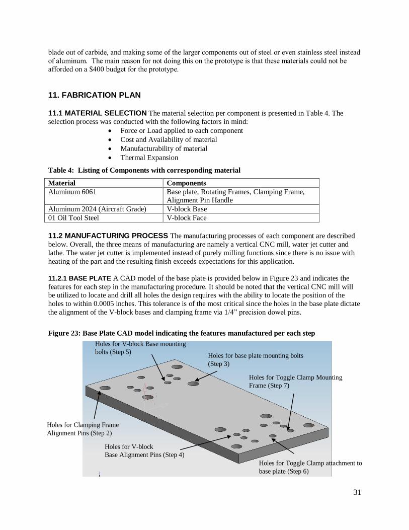
11.2.1 BASE PLATE A CAD model of the base plate is provided below in Figure 23 and indicates the
features for each step in the manufacturing procedure. It should be noted that the vertical CNC mill will be utilized to locate and drill all holes the design requires with the ability to locate the position of the
holes to within 0.0005 inches. This tolerance is of the most critical since the holes in the base plate dictate
the alignment of the V-block bases and clamping frame via 1/4” precision dowel pins.
Figure 23: Base Plate CAD model indicating the features manufactured per each step
Holes for Clamping Frame
Alignment Pins (Step 2)
Holes for V-block
Base Alignment Pins (Step 4)
Holes for base plate mounting bolts
(Step 3)
Holes for Toggle Clamp attachment to
base plate (Step 6)
Holes for Toggle Clamp Mounting
Frame (Step 7)
Holes for V-block Base mounting
bolts (Step 5)

32
The manufacturing procedure is as follows:
1.) Machine the purchased blank to the correct outer dimensions using a ban saw, then refining with a vertical mill.
2.) Drill holes for the dowel pins with a jobber drill that is 1/64 inch less than the diameter of the
dowel pins, then reamed with a reamer that is within 0.002 inch of the diameter of the dowel pin.
3.) Drill holes for base plate mounting with clearance for ¼-20 UNC bolts 4.) Drill holes for dowel pins used for V-block alignment
5.) Drill holes for V-block base mounting with clearance for ¼-20 UNC bolts
6.) Drill and tap holes for Toggle Clamp attachment to ¼-20 thread 7.) Drill holes for toggle clamp mounting frame with clearance for ¼-20 UNC bolts
All clearance holes for ¼-20 UNC bolts will be drilled accurately with a ¼ inch jobber drill. The clearance holes for the bolts which fasten the base plate to the turntable are counter bored to allow the
head of the bolts to be flush with the base plate.
11.2.2 V-BLOCK BASE A CAD model of the V-block base is provided below in Figure 24 and indicates the features described in each step in the manufacturing procedure.
Figure 24: CAD models of the V-blocks indicating the features manufactured. Bottom-Back
Isometric view (Left), Front Isometric view including V-block face (Right).
The manufacturing procedure is as follows:
1.) Machine the purchased blank to the correct outer dimensions using a ban saw, then refining with
a vertical mill. 2.) Drill dowel pin holes for horizontal and vertical alignment
3.) Drill and tap anchoring holes to ¼-20 thread
4.) Drill and tap alignment pin hole to ¼-20 thread 5.) Drill and tap anchoring holes for V-block face mounting to 10-32 thread
The required dowel pin holes were machined in the same fashion as the in the base plate since the dowel pins are used to align the V-block base onto the base plate. A separate V-block base is manufactured in
the same fashion with the exception of the threaded alignment pinhole, which does not exist in that
design.
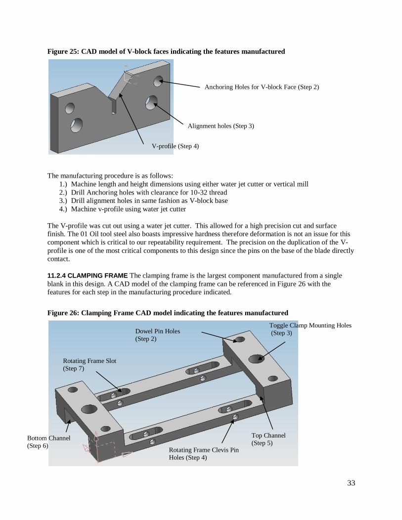
11.2.3 V-BLOCK FACE The 01 Oil tool steel will be bought as a 5 mm thick blank thus the thickness
dimension will not need to be altered. A CAD model of the V-block face is provided in Figure 25 (p. 33) with the features for each step in the manufacturing procedure indicated.
Anchoring Holes for
V-block Face (Step 5)
Dowel Pin Holes
(Step 2)
Anchoring Holes to Base Plate (Step 3)
Threaded Alignment Pin
Hole (Step 4)
Dowel Pin Holes (Step 2)
33
Figure 25: CAD model of V-block faces indicating the features manufactured
The manufacturing procedure is as follows:
1.) Machine length and height dimensions using either water jet cutter or vertical mill
2.) Drill Anchoring holes with clearance for 10-32 thread 3.) Drill alignment holes in same fashion as V-block base
4.) Machine v-profile using water jet cutter
The V-profile was cut out using a water jet cutter. This allowed for a high precision cut and surface finish. The 01 Oil tool steel also boasts impressive hardness therefore deformation is not an issue for this
component which is critical to our repeatability requirement. The precision on the duplication of the V-
profile is one of the most critical components to this design since the pins on the base of the blade directly contact.
11.2.4 CLAMPING FRAME The clamping frame is the largest component manufactured from a single
blank in this design. A CAD model of the clamping frame can be referenced in Figure 26 with the features for each step in the manufacturing procedure indicated.
Figure 26: Clamping Frame CAD model indicating the features manufactured
Dowel Pin Holes
(Step 2)
Toggle Clamp Mounting Holes
(Step 3)
Rotating Frame Slot
(Step 7)
Rotating Frame Clevis Pin
Holes (Step 4)
Top Channel
(Step 5) Bottom Channel
(Step 6)
Anchoring Holes for V-block Face (Step 2)
Alignment holes (Step 3)
V-profile (Step 4)

34
The manufacturing procedure is as follows: 1.) Machine the purchased blank to the correct outer dimensions using a ban saw, then refining with
a vertical mill.
2.) Drill dowel pin holes with same tooling and procedure as base plate
3.) Drill and tap holes to 5/8”-18 thread to mount toggle clamp 4.) Drill and ream four holes to 3/8” to house clevis pins for rotating frame pivot
5.) Remove top channel material using vertical mill ½” end mill
6.) Remove bottom channel material using vertical mill and ½”end mill 7.) Remove material for rotating frame slot using vertical mill and 3/8” end mill
It should be noted that since dowel pins are used to align the clamping frame to the base plate, the required holes were machined in the same fashion as the outer four dowel pin holes in the base plate.
11.2.5 ROTATING FRAME A CAD model of the rotating frame is provided below in Figure 27 which
indicates the features described in each step in the manufacturing procedure.
Figure 27: Rotating Frame CAD model indicating the features manufactured
The manufacturing procedure is as follows: 1.) Machine the purchased blank to the correct outer dimensions using a ban saw, then refining with
a vertical mill.
2.) Drill and tap alignment pin hole to ¼-20 thread 3.) Drill and ream clevis pin holes to same diameter as clevis pin
4.) Machine top width of part to correct thickness
5.) Machine inner profile using water jet cutter
Clevis Pin Joint Hole (Step 3)
Alignment Pin Hole (Step 2)
Bracket Contact
Face Profile (Step 5)
Top Width (Step 4)

35
The thickness of the top width and the inner profile are the most critical dimensions to this component. If
either dimension is much larger than specified the fixture cannot function.
11.2.6 TOGGLE CLAMP MOUNTING FRAME Provided below is a CAD model in Figure 28 which
indicates the features described in each step in the manufacturing procedure.
Figure 28: Toggle Clamp Mounting Frame CAD model indicating the features manufactured
The manufacturing procedure is as follows: 1.) Machine the purchased blank to the correct outer dimensions using a ban saw, then refining with
a vertical mill.
2.) Drill and tap mounting hole to ¼-20 thread 3.) Drill and tap Toggle Clamp Connecting anchor to ¼-20 thread
4.) Machine profile using vertical mill
11.2.7 ALIGNMENT PIN HANDLE Since the spring plunger alignment pin requires a handle, the following cylindrical handle was designed (Figure 29, p. 36). This design will thread into the spring
plunger alignment pin.
The manufacturing procedure is as follows:
1.) Machine the purchased round stock to max diameter
2.) Drill and tap mounting hole to ¼-20 thread at center of end of stock
3.) Turn the handle extension to specified diameter
Mounting Holes (Step 2)
Toggle Clamp Connecting anchor (Step 3)
Frame Profile (Step 4)

36
Figure 29: Knob attaching spring plunger allowing it to be adjusted by the operator
12. VALIDATION 12.1 REPEATABILTY To determine how well our prototype worked, the turbine blade was inserted
into the fixture and measurements were taken of the blade using the laser scanner. The setup is shown in
Figure 30. Then the blade was taken out of the fixture and re-inserted, and another measurement of the
blade was taken with the laser scanner. This will gave us an error vector and so we can see if the desired goal of +/- 20 microns is attained. This test also showed that the necessary parts of the blade were
exposed for scanning.
Figure 30: Setup for the laser scanning of the turbine blade for repeatability validation.
Handle max diameter (Step 1)
Handle Extension (Step 3)
Mating thread to spring plunger (Step 2)

37
The first test we performed was a 2.5 mm X 2.5 mm scan of a corner of the blade near the upper clamping
points. Three scans were done, and Figure 31 below shows the two scans which differ the most. Magnitudes of the difference among points were found to be 16µm +/- 5µm.
Figure 31: 2.5mm X 2.5mm scan of the turbine blade near upper clamping face
In order to determine the main sources of error, two more scans were done, with three trials for each scan.
The first of these tests involved a scan across the vane at a fixed z-coordinate about halfway up the blade.
This part of the blade would be expected to show larger magnitudes of error than before since it is farther away from the clamping faces. A curve was fit to the points taken across the x-axis, and these three
curves were compared against each other. The apex of each curve was measured and a maximum error of
14 µm +/- 9 µm was found in the x-direction and 37 µm +/- 20 µm in the y-direction.

38
Figure 32: Horizontal scan across the turbine blade, approximately halfway up the vane.
A vertical scan was done on the same part of the turbine blade to determine repeatability in the z-direction. Only two of the three trials of the vertical scan show the same profile of the surface roughness.
This is due to the fact that a slight shift in x-direction would cause the laser scanner to read a different line
on the blade. The same profile must be read to compare error in the z-direction, so this error was calculated by taking error between the green and red plots shown in Figure 33 (p. 39). Error in the z-
direction was found to be 2 µm +/- 1 µm, and in the y-direction the error is 31µm +/- 20 µm.

39
Figure 33: Vertical scan of the blade approximately halfway up the vane.
Since there are six error values for the y-direction, three from the horizontal scans and three from the
vertical scans, error is in the y-direction has been determined to be 34 µm +/- 24 µm. Table 5 below shows a summary of error, including absolute error, between six scans on the vane of the turbine blade.
Table 5: Summary of the error in each direction, including absolute error.
X error Y error Z error Absolute error
14 µm +/- 9 µm 34 µm +/- 24 µm 2 µm +/- 1 µm 37 µm +/- 23 µm
From Table 5 it is seen that the y-direction is the primary source of the absolute error. This direction is constrained by the threaded knobs and set screws on the rotating frames. The absolute error of 37 µm
falls within the specification since +/- 20 µm corresponds to an absolute difference of 40 µm.
12.2 WITHSTAND GRINDING FORCES Using a scale, we imposed 5 lb. forces in various spots on
the blade. After several forces had been exerted on the blade, the blade was be scanned again to ensure that previous measurements still hold. This was to ensure that the fixture will withstand grinding forces.
12.3 MASS OF FIXTURE The fixture needed to have a reasonably low mass for two reasons. The
fixture needed to be light enough to be transportable and it needed to be light for the stand that it may be implemented on, which has a rating of a maximum moment, as stated earlier in this paper. The test
associated with this is a simple one, simply obtain the mass of the fixture once it has been completed
using a scale or other mass reading device. The recorded mass of the fixture is 2.1 kg which falls under our 5 kg goal.

40
12.4 MATERIAL The material of the fixture has an impact on many areas. Unfortunately the material
used in our final design will not necessarily be the same material of our prototype. The prototype used
primarily aluminum due to cost restrictions. Therefore, a physical test will not suffice for seeing if the choice of material was correct for every part of the fixture. However, if we observe no yielding or
excessive deformation while the blade is being held, the material choice for the prototype will be
considered sufficient, and this would only be improved by our final design.
12.5 GEOMETRY The geometry of the fixture is important as to whether or not it achieved the desired
task. There is not a true scientific test for this technical specification; it was proved sufficient by the
loading test. Since the necessary faces of the blade are exposed for grinding and scanning, then this has proven to be a good geometry. This can also be proven in the CAD model of the fixture with a CAD
model of the blade inserted in the fixture. This way, we can easily see which faces of the blade are
exposed for scanning and grinding. Therefore, this specification was proven well before the prototype
was built. Also, the fixture fitting the bolt pattern in the lab is part of the geometry as well, and was proved simply by attaching the fixture to the bolt pattern.
12.6 THERMAL EXPANSION In order to keep high repeatability in a non rigorously temperature
controlled environment, our fixture must not be sensitive due to thermal expansion. However, the environment that this will be in will not be subjected to sudden temperature changes during operation.
Even though this design may be on a factory floor at one point, we are still making the prototype for the
ERC lab, which only will see a change in temperature of a few degrees, and could see none while the fixture is in use. Therefore, there is no real need to test for thermal expansion if the change will be
negligible in the testing of the prototype.
12.7 QUALITY CONTROL To test durability and robustness of the fixture, we loaded and unloaded
several blades multiple times. While we do not have the resources to test the fixture against long-term
fatigue or durability, we were able to see key wearing points and determine whether or not there are any
points of concern.
12.8 LOADING TIME We timed how long it takes to insert the blade in the fixture and clamp down all
toggle clamps and spring plungers. This process should be completed within 20 seconds. Mr. Zalenski
boasts an impressive loading and unloading time within 14 seconds.
12.9 SIGNALS The signal involved will be a very simple one. The toggle clamps that we are using will
go into a locking position when the blade is completely fixture down. This locking is very apparent to the
user and will serve as an adequate signal for whoever is using the fixture.
13. DISCUSSION Our validation results show that the error in the z-direction is extremely precise due to our choice in using
V-blocks to hold the blade vertically. Another strong advantage of our fixture is that the only energy input is manual energy from the operator. Additionally the fixture is constructed from readily available
materials and after its life cycle can be stripped down and recycled.
In looking closely at the validation data, the main source of the error is due to the blade rotating on the V-
blocks. This error is most likely due to the fact that the reference points (the set screws in the rotating
frames) in that direction are not directly fixed to the base. Any movement in the rotating joints at the
clevis pins or the axial movement at the dowel pins will result in the reference points not being repeatable. This could be fixed by designing a bracket coming up from the base which specifically
contacts the blade, fixing it in the axis of rotation about the V-blocks. The corresponding clamping face

41
could be in the form of a rotating knob, as it is currently, but mounted to another fixed bracket on the
opposite side of the blade.
14. RECOMMENDATIONS Upon validation of our final design, we realized some potential problems with our final product. This
section will describe these potential problems in detail, as well as provide a recommended solution so that
these problems do not arise during later use of the final design.
The first recommendation is to modify the bolts on the rotating frames of the fixture. Currently, the bolts
directly contact the turbine blade as they align the turbine blade, which creates metal to metal contact
while they are moving relative to each other. This can cause wear and minor deformations on the blade itself. Our recommendation is to put a piece of rubber on the bolt that will contact the blade. This will
eliminate the metal to metal contact in this instance, and allow the blade to contact a softer surface that
would not scratch or deform the blade.
The next recommendations also involve the bolts on the rotating frame. When doing the validation tests,
we not only saw the precision errors involved with the fixture, but in exactly what direction those errors
were located in. From this, we were able to see that in the z-direction, the blade varied by only two microns. This was the direction controlled by the V-blocks, which leads us to believe that design
improvements are not necessary on those parts. Since the vast majority of the error was related in the
blade rotating about its pins on the V-blocks, we could attribute this error to the bolts in the rotating frames. The first recommendation for improving this would be careful alignment of the set screws on the
rotating frames, so that they are perfectly aligned and do not cause an unwanted torque on the blade that
could lead to inaccuracies. Another way of doing this would be re-cutting the rotating frames with small contacting protrusions so that the frame contacts the blade directly, improving the error in this aspect.
Finally, the dowel pins that align the clamping frame must be periodically lubricated to keep the fixture
from binding up. After months of use, there is a chance that the fixture could bind up, and keeping the pins lubricated will decrease wear over time that leads to inaccuracies.
15. SUMMARY During turbine inspection, it is desirable to be able to correct imperfections at the same station. In order
to accomplish this, the fixture must be able to both hold the blade to a very high level of repeatability, and
withstand grinding forces without deflection of the blade. In addition, the fixture must not occlude key features of the blade to be scanned by the laser. The fixture is to be mounted on a rotating turntable with
a tilting axis, and the fixture must be lightweight as to not exert a high moment on the tilting axis. Since
the fixture is intended for factory use in the long-term, it is to be quick and easy to use.
Our fixture solves the problem in two steps: one by accurately positioning the blade, and the second by
securing the blade with accurate force to withstand the grinding and tilting conditions. Our fixture uses
the 6-point jig and fixture method to prevent the blade from rotating and traversing in the x, y and z directions. The fixture was fabricated using a high precision CNC mill and water jet cutting which
produced very accurate parts. A combination of superior design and stellar machining resulted in a
product that sufficiently satisfies all design requirements and specifications. The fixture elegantly solves the design problem by simple design and ease to use, while maintaining high accuracy and repeatability.
We are proud to report that the fixture holds the blade to a position within 37 µm.

42
16. REFERENCES
[1] Nee, A.Y.C.; Whybrew, K.; Senthil Kumar, A. Advanced Fixture Design. Springor-Verlag, London,
1995.
[2] Joshi, P.H. Jigs and Fixture Design Manual. McGraw-Hill Company, New York, 2003.

43
APPENDIX A: ABOUT THE TEAM Nick Zalenski, the team treasurer, is from Birmingham, MI. From the
beginning of his college career he knew he wanted to go in Mechanical
Engineering because of his interests in physics and the automotive field. In his past internships he has gained experience in research on fuel tank
inerting at Boeing and testing prototype components of emission systems at
Ford. His future plans are to intern as a business analyst for Capital One after graduating this coming April, and returning to University of Michigan
in the fall in pursuit of a Master’s degree in Industrial and Operations
Engineering. In his free time he enjoys golfing in the summer and skiing in
the winter. His most recent hobby is in the art of disc jockeying.
Craig Stephen Stanfill was born on October 12, 1985 in Monroe, Michigan. Fittingly enough he was named after his father Stephen Craig who has the
same birthday date in 1958. Craig graduated Summa Cum Laude from
Monroe High School in 2004 where he also lettered in both varsity Football and Baseball. He was enrolled at the University of Michigan in the fall of
2004 and is currently pursuing a degree in Mechanical Engineering. In
January 2006 Craig was employed as a Co-Op engineer at TRW Automotive
until that September and returned again for a second summer the following year (2007). While at TRW he has worked in the hydraulic braking
department with the slip control systems development group. Currently his
summer hobbies include fishing, water sports namely skiing and wakeboarding, golfing, and ultimate Frisbee.
Nick Moroz was born on October 2, 1983 in Chicago, Illinois. He was raised in Northville, Michigan and graduated from Northville High School in 2002. He
attended Albion College and received a Bachelor’s of Arts degree in Physics
and Mathematics in 2006. He then enrolled in the Mechanical Engineering
program at the University of Michigan in Ann Arbor. He has conducted research on particle accelerators at Albion College and published a paper for a
novel design for a faraday cup, Performance Enhancement Study of an
Electrostatic Faraday Cup Detector (J.D. Thomas, G.S. Hodges, D.G. Seely, N.A. Moroz, T.J. Kvale). He is currently employed at the University of
Michigan Dearborn’s Additive Manufacturing and Processing Laboratory as a
full-time Research Engineer. His current research projects include a new
technique for silicon deposition and directional cooling.
Patrick Henry Maloney was born on December 20, 1985 in Walnut Creek,
California, located just east of San Francisco. He was raised in Danville, CA and there he graduated from Monte Vista High School in 2004 with honors.
He then enrolled at the University of Michigan in Mechanical Engineering.
While attending Michigan, Patrick was a member of the Michigan Marching Band for four years, and is still an avid musician. He has worked for various
mechanical contractors doing construction labor, as well as estimation and
project management. Last summer, he worked for the Trane Company
focusing on research for heat exchangers on screw and centrifugal compressor based chillers. His current hobbies include alpine skiing, water
skiing, football, golf, and playing music.

44
APPENDIX B: ENGINEERING DESIGN CHANGES B.1 ELIMINATION OF ADJUSTMENT KNOB
Figure B.1: Omitted adjustment knob
The purpose of this knob was to aid in tightening down the spring plunger against the turbine blade. The
decision to eliminate this knob was made since the spring plunger had adequate displacement, making its movement unnecessary. Instead of the blade being placed straight down into the V-blocks, one end is
loaded first, with the user pushing it against the spring plunger to allow for the other end to be loaded into
the V-blocks.
B.2 ELIMINATION OF TOGGLE CLAMP MOUNTING FRAME
Figure B.2:Omitted toggle clamp mounting frame
The purpose of this frame was to give the adjustment knob (previously mentioned) clearance, otherwise it
would interfere with the toggle clamp mounting bolt. Since the adjustment knob was deemed unnecessary, this extra mounting frame was not needed.

45
B.3 REPLACEMENT OF SPRING LOADED KNOB WITH THREADED KNOB
The displacement of the spring loaded knobs was less than expected and as a result the spring loaded
knobs were replaced with simple threaded knobs. Both knobs are pictured below.
Figure B.3: Spring loaded knob (Left), Threaded knob (Right)
B.4 ADDITION OF SET SCREWS In order to increase repeatability, set screws were used as reference points in aligning the blade against the rotating frames. These set screws were put in the rotating frames opposite from the knobs. The
increased hardness of these screws over the aluminum rotating frame makes it a better reference face for
the blade.
Figure B.4: Added set screws

46
APPENDIX C: DESIGN ANALYSIS C.1 DESIGN FOR MATERIALS Major Component: V-block Face Function: Support the load of the blade’s locating pins when the clamping force is applied.
Objectives: 1. Maximize hardness and stiffness
2. Support 100 lb load
3. Machinable Constraints: Shape is specified, support 100 lb load without failing, readily available, economical. Can be
cleaned easily with organic solvents. Recyclable.
Indices: M = yield strength * Young’s modulus / cost Price < $100 per lb
Yield strength > 200 ksi
Recyclable Very good with organic solvents and fresh water
Top 5 Choices:
-Nickel-Cobalt-Chromium Alloy, AEREX 350 (cold worked & aged) This material was chosen because it has the highest stiffness and strength. It is typically used as a
high temperature fastener for gas turbines. It has very low creep and thermal expansion making it
ideal for precision parts. It can be machined with carbide tools or with laser or water jet cutting.
It is also the most expensive of the materials.
-Wroght martens. Stainless steel, AISI 420, tempered @204C
This material also has sufficient stiffness and strength but is also very cheap, $0.5364-0.6509. It is also readily available and can be machined using standard tools.
-Multiphase alloy, MP159, ST, Cold drawn and aged This material also boasts high strength and stiffness. However, it is difficult to obtain. It can be
machined with carbide tools or with laser or water jet cutting.
-Tungsten, Commercial Purity, annealed

47
Very strong and stiff, but also expensive compared to the other materials. Readily available. It
can be machined with carbide tools or with laser or water jet cutting.
-Multiphase alloy, MP35N, ST; Cold drawn and aged
Very similar to MP159; very strong and very stiff. It can be machined with carbide tools or with
laser or water jet cutting.
Major Component: Clamping Frame
Function: Slides on dowel pins and transfers clamping force from toggle clamps to rotating frames. Objectives: 1. Maximize stiffness
2. Support 100 lb load
3. Machinable 4. Maximize cost
5. Minimize weight
Constraints: Shape is specified, support 100 lb load without failing, readily available, economical. Can be
cleaned easily with organic solvents. Recyclable. Indices: M = yield strength * Young’s modulus / cost * density
Price < $10 per lb
Yield strength > 200 ksi Recyclable
Very good with organic solvents and fresh water
Top 5 Choices:
-Wrought aluminum alloy, 7055 Very lightweight, yet still strong enough to handle the loads applied. Also very cheap and readily
available. Can be machined with standard parts. Not very durable.
-Wroght magnesium alloy (EA55RS)
Similar to aluminum in density and price, but a bit stronger. Can be machined with standard
parts. Again, not very durable.
-Zinc-Aluminum Alloy, “Kolroy 2573”

48
This material also boasts high strength and stiffness and also has good impact durability. Very
good machining properties and cheaper than stainless steel.
-Wrought Aluminum alloy, 8091, T6
Highest strength casting aluminum alloy with good stiffness and durability. Poor machining
properties.
-Duralcan Al-20Al203
Aluminum alloy 2014 matrix with alumina particulates. Very hard and stiff and durable. Difficult to machine. It can be machined with carbide tools or with laser or water jet cutting.
C.2 DESIGN FOR ASSEMBLY Each part of the assembly process requires the following assembly times:
Inserting ¼” dowel pin: 2 X 3.5s
Inserting 3/8” dowel pin: 2 X 3.5s
Inserting and securing 10-32 bolt: 1.8 + 6s
Inserting and securing ¼” bolt: 1.8 + 6s
Inserting and securing ¼” bolt (obstructed access): 1.8 + 8.5s
Securing ¼” nut: 1.13 + 6s
Inserting clevis pin: 1.5s
Securing clevis pin retainer ring: 9s
Inserting ¼” set screw: 1.9 + 6s
Inserting ¾” threaded knobs: 1.5 + 6s
Inserting toggle clamps: 1.5 + 6s
Inserting ¼” spring plunger: 1.8 + 8.5s
Number of parts required to assemble:
(6) ¼” dowel pins
(4) 3/8” dowel pins
(4) 10-32 bolts
(6) ¼” bolts
(4) ¼” bolts (obstructed access)
(2) ¼” nuts
(4) clevis pins
(4) clevis pin retainer rings
(2) ¼” set screws
(2) ¾” threaded knobs
(2) toggle clamps
(1) spring plunger
Total assembly time: 302 seconds, or approximately 5 minutes.
In order to reduce assembly time, the blocks with attach to the base and the V-block faces and become one part with the base. This reduces three parts into one, and eliminates four dowel pins and four bolts.

49
The V-block faces must still be separate parts since aluminum is not hard enough for this part, and steel is
too heavy to make up the entire base. In securing the V-block faces to the base, two dowel pins are still necessary for precise alignment, however only one bolt per V-block is necessary for securing the parts
together. The four bolts which securing the base to the turntable can be reduced to three, and if they are
spaced out away from the dowel pins securing the V-block faces, they will no longer be obstructed, thus
reducing assembly time. Furthermore, the set screws can be eliminated if protrusions are designed in the rotating frames providing accurate reference faces.
The new parts list required for assembly is as follows:
(2) ¼” dowel pins
(4) 3/8” dowel pins
(2) 10-32 bolts
(5) ¼” bolts
(2) ¼” nuts
(4) clevis pins
(4) clevis pin retainer rings
(2) ¾” threaded knobs
(2) toggle clamps
(1) spring plunger
This results in an improved assembly time of 193s or approximately 3.2 minutes. This is a reduction of
approximately 40% in assembly time.
C.3 DESIGN FOR ENVIRONMENTAL SUSTAINABILITY
The two materials that were chosen from using CES are Nickel-Cobalt-Chromium Alloy,
AEREX 350 (cold worked & aged), used for the V-block faces, and Wrought aluminum alloy,
7055, used for the clamping frame. NiCr20Co18Ti I and AlZnCuMg (7075) I were chosen in
SimaPro 7.0 to simulate these materials. The materials were compared using Eco-Indicator 99. Determining the mass of each element used:
Volume of V-block face: 6445.17 mm3
Density of AEREX 350: 8.62 g/cm3
Mass of AEREX 350: 0.056 Kg
Volume of V-block face: 147702.56 mm
3
Density of Al 7055: 2.80 g/cm3
Mass of Al 7055: 0.41 Kg
SimaPro 7.0 comparison of materials (Single score)
The single score plot, Figure C.1 (p. 50), reports on the environmental indicators that are aggregated into
normalized scores using weighting factors. The single score gives a visual comparison of the two material’s overall effect on the environment in the form of their impact on human health, ecosystem
quality, and use of resources. The single score shows that for both materials the environmental footprint
caused by the use of resources overwhelms that of human health and ecosystem quality. For this reason,
the resources category is the most important of the study. It also shows that the super-nickel alloy, AEREX 350, has a much higher environmental impact than the aluminum alloy.

50
Figure C.1: Normalized single score comparison of AEREX 350 and Al 7055.
The damage assessment plot, Figure C.2 (p. 51), shows the comparison of discrete damages that the
materials have on the environment. These damages account for items such as minerals, land use, climate
change, etc. The plot shows that the super-nickel alloy, again, has the higher impact on the environment in most categories. However, this plot is not normalized; it is misleading to suggest that the damage
assessment describes the super-nickel alloy as having the overall larger environmental footprint.

51
Figure C.2: Damage assessment comparison of AEREX 350 and Al 7055.
SimaPro 7.0 also produces a normalized plot, Figure C.3 (p. 52), of the damage assessment that shows the actual values of the affects on human health, ecosystem quality, and resources that each material has.
This direct comparison shows how much each material actually affects each category. The normalized
plot shows how massive the drain on resources the super-nickel alloys is compared to the aluminum alloy.

52
Figure C.3: Normalized plot of environmental impact comparison of Al 7055 and AEREX 350.
SimaPro 7.0 also outputs an inventory of the amounts of resources used by each material. The masses of these resources were then converted into kilograms (kg) and then plotted in Figure C.4 (p. 53). The
material comparison does not normalize the resources used to the masses of each material used in the
fixture. The plot shows that the aluminum alloy actually used more overall resources, however the mass
of the aluminum alloy used in the fixture is almost ten times larger than that of the super-nickel alloy.

53
Figure C.4: Comparison of resources used to create materials.
After a thorough comparison of the two materials using SimaPro 7.0, it is quite obvious that the AEREX
350 has an overall larger impact on the environment. The aluminum is also recyclable, in that it can be melted and reused for another application, whereas the super-nickel alloy cannot be economically
recycled. Overall, the Al 7055 has a much smaller environmental impact than the AEREX 350, even
though nearly ten times as much Al 7055 is used in the fixture than AEREX 350. C.4 DESIGN FOR SAFETY Resulting from a risk assessment of our final design and prototype is the table provided below which
indicates the major risks and who is involved with each. The differences in the final design intended for use as an inspection only and on the factory floor as to sustain grinding forces also impacts the risk
assessment.
Table C.1: Risk Assessment of Fixture Design for inspection purposes only
Major Risk Who is Involved
Pinch Points in fixture motion Operator of Fixture
Loading Force/Fatigue Operator
Exposure to Laser Operator/ Passer by
Table C.2: Risk Assessment of Fixture Design for grinding purposes
Major Risk Who is Involved
Pinch Points in fixture motion Operator of Fixture
Loading Force/Over exertion Operator
Fracture of Fixture during Grinding Operator/ Passer by
Improper Loading resulting in flying objects Operator/ Passer by
Jamming of Part in fixture Operator
0
0.2
0.4
0.6
0.8
1
1.2
1.4
1.6
1.8
2
raw air water waste
Mas
s (K
g)
NiCr20Co18Ti I
AlZnCuMg (7075) I

54
The output from the design safe analysis is very similar in nature to the tables described above. In all
cases simple safety measures and proper training would be implemented which results in an overall low risk design. The design safe analysis was also very sensitive to the application of the fixture. In both
cases labels should be implemented to warn of any pinch points as well as signs posted warning passers-
by of a laser in use. Eye protection is recommended for the operator in case the fixture is incorrectly
loaded and small parts break off the fixture. Adequate training around either the laser inspection or grinding stations will reduce this risk. Overall the calibration of the fixture clamping mechanism results
in the user not requiring a great deal of force to operate and thus this risk is very low.
The differences between FMEA (Failure Mode Effects Analysis) and a risk assessment are very subtle. In both cases the risk or failure is ranked by the severity, how often there is exposure to this risk and the
probability of the risk or failure occurring. The difference however is that FMEA actually goes more in
depth in the effects analysis of the failure. This is most commonly with the effects to the customer but also deals with the level of design changes required to alleviate the chance of failure.
The difference between acceptable risk and functional risk is related to who or what is involved in the
risk. If the operator or passerby is involved in the risk then a zero risk level must be maintained. However,
if the functionality of a part is involved then an acceptable amount of risk maybe be developed. This distinction shows up in our design as to ensure a zero risk to the failure of any component since the
operator is directly contacting the fixture design. There is an acceptable amount of risk taken with regards
to possible deformation of the fixture over time which may result in faulty performance however still maintaining a zero risk to the user and operator. The design also incorporates a manual insertion of the
turbine blade to the fixture as well as manual clamping force. The design was optimized as to require
minimal user input force which results in a minimal risk level. C.5 DESIGN FOR MANUFACTURING The fabricated final design fixture is to be immediately used in the ERC/RMS Laboratory to aid in the
inspection of the specific turbine blades. The initial scope of the project requires only one fixture to be produced. However if the process that the ERC/RMS lab uses becomes useful to a company such as
General Electric, the production volume would be closer to 100 units. The ultimate goal of the fixture is
to be implemented on the factory floor in an assembly line styled inspection and grinding station for this specific turbine blade design. Realistically, the maximum number of fixtures that would ever need to be
produced is 500; incorporating producing spare fixtures.
The two components chosen in the Material Selection Assignment are the V-block faces, made from Nickel-Cobalt-Chromium Alloy, AEREX 350 (cold worked & aged), and the clamping frame, made from
Wrought aluminum alloy, 7055.
The V-blocks faces are made from a super-nickel alloy which is can be shaped using a few techniques.
The V-block faces have a simplistic shape. Since the maximum production volume of the V-block faces,
1000 parts, is relatively low computer numerically controlled (CNC) milling, Figure C.5 (p. 55), should be used to shape and form the part. Since the pieces can be machined from a rectangular blank CNC
milling should be the most cost effective method; the economic batch size for milling is 1 to 1 x 10⁷ parts.
Any production quantity can be economic. CNC milling can achieve tolerances of 7 x 10⁻⁴ to 0.01 inches,
which is sufficient for the V-block faces. The surface roughness is 0.04 to 0.98 mil which is also sufficient for the fixture. The relative tooling cost is low, the relative equipment cost is high, and the
labor intensity is medium. The only impact on the environment would be problems posed by cutting
fluids and lubricants. Since AEREX 350 is a hard material, lubricants and cutting fluids would be necessary to form parts. Yet, the parts are small and the amount of machining per part is low. Surface
treatment should not be necessary for the V-block faces. Bolts can be used as fasteners to join the V-
block faces to the rest of the fixture.

55
Figure C.5: Examples of methods of milling workpieces. Computer numerical control (CNC) is
used to guide the mills.
The clamping frame is made from aluminum alloy 7055, which is a harder form of aluminum than the
6000 series. The clamping frame is made from a blank of aluminum which needs to be shaped, drilled,
threaded, and surface treated. Since there is already the capitol cost associated with the CNC machining for the V-block faces and the production volume of clamping frames is low, the best method for shaping
the clamping frame would be CNC machining. CNC machining of aluminum 7055 is a very quick and
easy process, the material shows little resistance or tool wear. Need for the use of lubricants and cutting
fluids when milling aluminum is also minimal. The same parameters for tolerance, surface finish, costs, and environmental concerns that applied to the machining of the V-block faces apply to the machining of
the clamping frame. In addition to shaping the clamping frame, an anodizing surface finish shown in
Figure C.6, will be utilized to harden the outer layer of the clamping frame and increase the scratch resistance. The machine cost of anodizing is high, but the tooling cost is very low. The anodizing layer
will act as a protecting coat from damage to the clamping frame.
Figure C.6: The process of anodizing a workpiece, which acts as the cathode of the process, in order
to achieve an oxidizing surface finish that is harder and more wear resistant than the original
material.

56
Utilizing these manufacturing processes allows the production of approximately 100 fixtures to be made
with high accuracy and consistency; two key concerns of the fixture. Since the fixtures main components will be CNC machined they will be economical, but they will also receive a great deal of instantaneous
critique. The manufacturer is in close proximity to the CNC machining processes and act as quality
control as well as production. This marriage of manufacture and critique will produce consistently
working fixtures that can be utilized on the factory floor or in the laboratory.

57
APPENDIX D: BILL OF MATERIALS Part Name Qty Material Color/Finish Size
Clevis Pin with retaining ring 4 18-8 Stainless Steel Brushed 1" length 5/16" diameter
Toggle Clamp 2 18-8 Stainless Steel Brushed 3-9/64" height
1/4"-20 X 3/4" Socket Cap Screw 8 Alloy Steel Black Oxide 1/4-20 thread 3/4" length
1/4"-20 X 2" Socket Cap Screw 2 Alloy Steel Black Oxide 1/4-20 thread 2" length
Dowel Pin Stock 1 High Speed Steel Ground 1/4" diameter 12" length
3/8" Diameter Dowel Pin 4 Alloy Steel Ground 3/8" diameter 2-/12" length
1/4" Diameter Dowel Pin 4 Alloy Steel Ground 1/4" diameter 3/4" length
Set Screw 1 18-8 Stainless Steel Brushed 1/4"-20 thread 1-1/4" length
Loctite 271 Adhesive 0.5 ml Liquid Adhesive Black 0.5 ml
Aluminum Blank 1 Al Alloy 6061 Ground 3-1/2" diameter 3" thick
Steel Blank 1 01 Tool Steel Ground 5mm thick 25mm width 1m length
10-32 1/2" length Socket Cap Screw 4 Alloy Steel Black Oxide 10-32 thread 1/2" length
Aluminum Blank 1 Al Alloy 2024 Ground
5/8" Thick, 1-1/2" Width, 1'
Length
Aluminum Blank 1 Al Alloy 6061 Ground 3/8" Thick, 5" Width, 1' Length
Aluminum Blank 1 Al Alloy 6061 Ground
1-1/2" Thick X 6" Width X 1'
Length
Aluminum Blank 1 Al Alloy 6013 Ground 1/2" Thick, 4" X 12"
Spring Plunger without handle 2 18-8 Stainless Steel Brushed 1/4"-20 thread 1-1/4" length
Steel Knob with Threaded Stud 2 Alloy Steel Black Oxide
1/4" - 20 X 1-1/4" Threaded Stud,
3/4" Diameter

58
APPENDIX E: INDIVIDUAL PART DRAWINGS

59

60

61
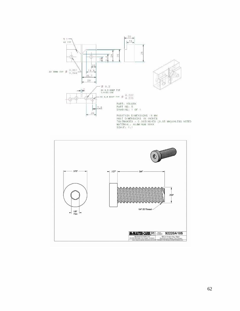
62
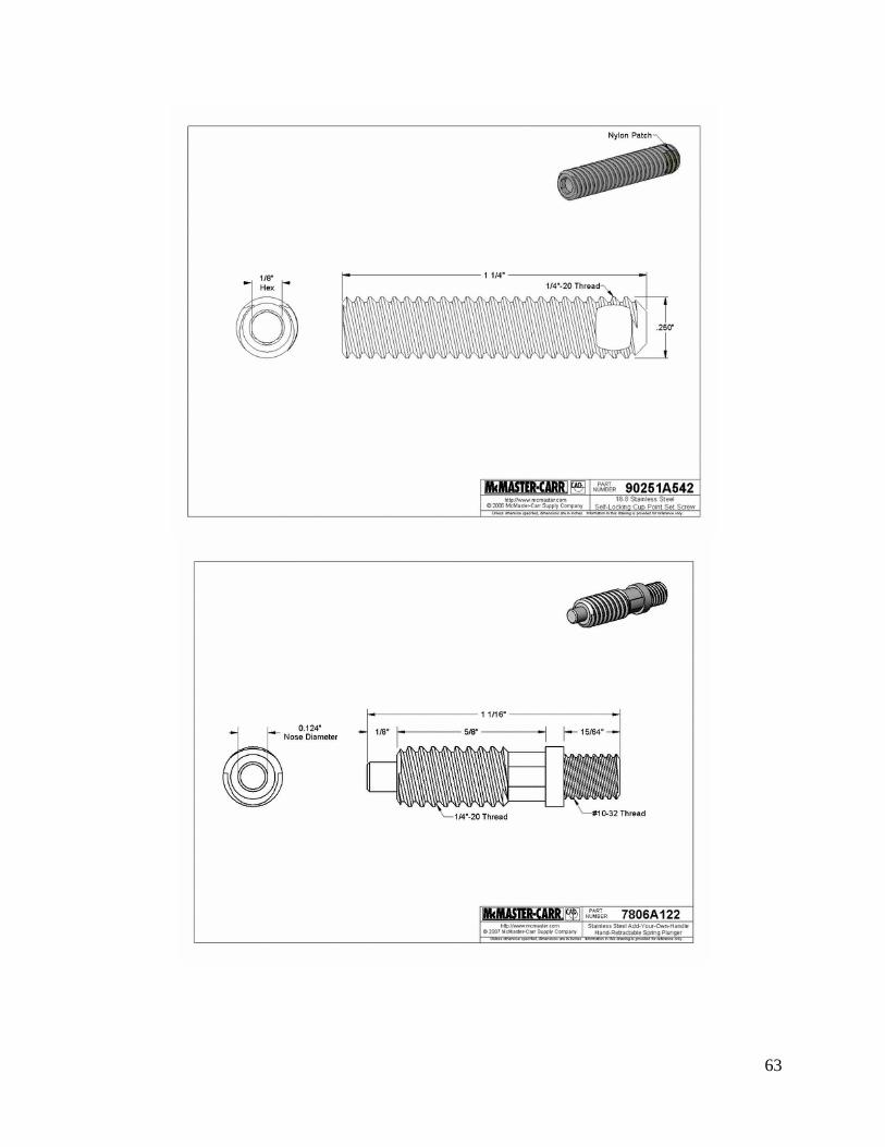
63

64

65
APPENDIX F: DESIGN CONCEPTS Design 1: Clamp and Hammers
Design 2: Total Profiles

66
Design 3: Wedge and Pin
Design 4: Use Inverted Cone Design 5: Rotate Clamps Design 6: Sprung Sides

67
Design 7: Clamp down on rollers

68
Design 8: Spring Loading

69
Design 9: Linkage profile with V-blocks
Table F.1: Other concepts
Positioning Locking Contacting
Design 10 Rigid Guides Eccentric Pins
Design 11 Sprung Sides Eccentric Profiles
Design 12 Wedges Piston Torque Wrench
Design 13 Rigid Guides Linkage V-block
Design 14 Collets Torque Wrench Wedge