Three-Face Blade Technology · the tool life, compared to 2-face grinding with permanent front face...
9
Three-Face Blade Technology Dr. Hermann J. Stadtfeld The Gleason Works, Rochester, New York Three-Face vs. Two-Face In order to utilize the full potential of 3-face ground and all around coated blades the cutter head slot inclination of 4.42° as it is used in the Pentac-FH cutter system is not sufficient. In case of 2-face ground blades, the front face remains untouched during the re-sharpening of only pressure angle and clearance side of the blade. The front face of 2-face blades is parallel to the blade shank and has a permanent coating. After re-sharpening, the blades are ready to be built in the cut- ter head. If blades should be all around coated, then it is recommended to grind in addi- tion to the side relief surfaces also the front face. The reason is the continuous buildup of coating layer on the front face if no stripping between coatings occurs. Although it is possible to strip the front face coating chemically before every re- coating, this would involve additional cost and results in a degradation of the carbide under the repeatedly stripped surface. In case of all-around coating it is recommended to grind the front face of the blades also in order to remove the previous coating and utilize the possibil- ity to achieve more optimal top rake and side rake angles with a different front face orientation. The “package” 3-face grind- ing and all-around coating can double the tool life, compared to 2-face grinding with permanent front face coating. Three-face grinding of blades which will be utilized in a cutter head with 4.42° of slot tilt angle is very limited with the maximal achievable top rake angle, which is around zero in the left graphic in Figure 1. If the same blade was used in a cutter head with a 12° slot tilt angle as shown to the right in Figure 1, then the achieved top rake angle would be 7.58°. This freedom allows in all cases of differ- ent gear geometries and cutting kinemat- ics to maintain a slightly positive top rake angle. Another important factor for manu- facturing cost per part is the relationship between slot tilt angle and number of re-sharpenings. In order to accomplish an effective top rake angle of e.g. 2° on a blade which is built in a cutter head with a 4.42° slot inclination angle, a Δ δ (Fig. 1) of 2.42° is required. This is represented by the left graphic in Figure 2. The cleanup amount of Δs normal to the surface will require a large blade top down Δl 1 . If a top rake angle of 2° in the cutting pro- cess should be realized in a cutter with 12° slot tilt angle, then the blade hook angle in blade grinding will be 10°, as shown in the right graphic in Figure 2. The relationship between top down Δl 2 and front face clean up Δs is becoming more favorable by increasing the slot tilt angle. The number of resharpenings for 3-face grinding in case of a 12° cutter slot tilt angle is 2.7 times higher than that of a 4.42° cutter slot tilt angle. The limits for the highest realistic slot inclination angles in cutter heads are given Figure 1 Top rake angle as function of slot inclination (slot tilt angle). Δγ min Δγ min Figure 2 Relationship between top down amount and blade hook angle. Δs Δs Δl 1 φ 1 φ 2 Δl 1 = Δs sin φ 82 GEAR TECHNOLOGY | November/December 2017 [www.geartechnology.com] technical
Transcript of Three-Face Blade Technology · the tool life, compared to 2-face grinding with permanent front face...
Three-Face Blade TechnologyDr. Hermann J. StadtfeldThe Gleason Works, Rochester, New York
Three-Face vs. Two-FaceIn order to utilize the full potential of 3-face ground and all around coated blades the cutter head slot inclination of 4.42° as it is used in the Pentac-FH cutter system is not sufficient. In case of 2-face ground blades, the front face remains untouched during the re-sharpening of only pressure angle and clearance side of the blade. The front face of 2-face blades is parallel to the blade shank and has a permanent coating. After re-sharpening, the blades are ready to be built in the cut-ter head.
If blades should be all around coated, then it is recommended to grind in addi-tion to the side relief surfaces also the front face. The reason is the continuous buildup of coating layer on the front face if no stripping between coatings occurs. Although it is possible to strip the front face coating chemically before every re-coating, this would involve additional cost and results in a degradation of the carbide under the repeatedly stripped surface. In case of all-around coating it is recommended to grind the front face of the blades also in order to remove the previous coating and utilize the possibil-ity to achieve more optimal top rake and side rake angles with a different front face orientation. The “package” 3-face grind-ing and all-around coating can double the tool life, compared to 2-face grinding with permanent front face coating.
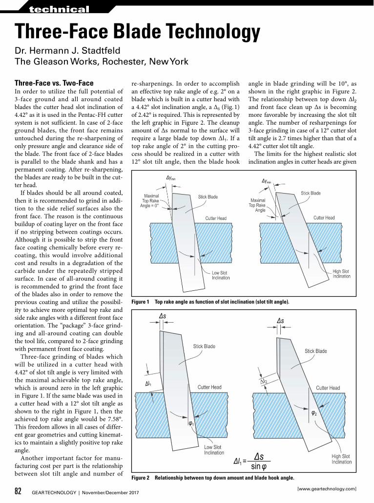
Three-face grinding of blades which will be utilized in a cutter head with 4.42° of slot tilt angle is very limited with the maximal achievable top rake angle, which is around zero in the left graphic in Figure 1. If the same blade was used in a cutter head with a 12° slot tilt angle as shown to the right in Figure 1, then the achieved top rake angle would be 7.58°. This freedom allows in all cases of differ-ent gear geometries and cutting kinemat-ics to maintain a slightly positive top rake angle.
Another important factor for manu-facturing cost per part is the relationship between slot tilt angle and number of
re-sharpenings. In order to accomplish an effective top rake angle of e.g. 2° on a blade which is built in a cutter head with a 4.42° slot inclination angle, a Δδ (Fig. 1) of 2.42° is required. This is represented by the left graphic in Figure 2. The cleanup amount of Δs normal to the surface will require a large blade top down Δl1. If a top rake angle of 2° in the cutting pro-cess should be realized in a cutter with 12° slot tilt angle, then the blade hook
angle in blade grinding will be 10°, as shown in the right graphic in Figure 2. The relationship between top down Δl2 and front face clean up Δs is becoming more favorable by increasing the slot tilt angle. The number of resharpenings for 3-face grinding in case of a 12° cutter slot tilt angle is 2.7 times higher than that of a 4.42° cutter slot tilt angle.
The limits for the highest realistic slot inclination angles in cutter heads are given
Figure 1 Top rake angle as function of slot inclination (slot tilt angle).
Δγmin Δγmin
Figure 2 Relationship between top down amount and blade hook angle.
Δs Δs
Δl1
φ1
φ2
Δl1 = Δssin φ
82 GEAR TECHNOLOGY | November/December 2017[www.geartechnology.com]
technical

by the cutter design and manufacturing, as well as the higher tendency of the cutting forces to push the blades axially into the slots during the cutting process.
Blade Parameter Definitions and Geometry CalculationTwo of the most important input parame-ters of the blade geometry calculation after the pressure angle are the effective side rake angle, which indicates the “sharp-ness” of the blade, and the effective cut-ting edge hook angle, which indirectly defines the top rake angle. It might be important at this point to mention that for cutting performance and good tool life, the effective cutting edge hook angle is the most important parameter. Because top rake angle and effective cutting edge hook angle are connected, the 3-face blade calculation program attempts to define a blade geometry which achieves the desired effective cutting edge hook angle. Only in cases where this is not possible due to geometry limitations, the closest possible value will be used as the result.
In order to obtain the effective angles, the relationship between the cutting velocity vector (Fig. 3) and the blade coordinate system in Figure 4 has to be considered. The blade side rake angle shown in Figure 4 is equal to the effec-tive side rake angle, if the indicated cut-ting direction is equal to the x-axis of the blade coordinate system. The effective cutting edge hook angle (vs. the blade hook angle) is shown in Figure 5. Each material removal from the blade front will change the cutting velocity vector direction in Figure 4 and therefore will also change the orientation of the cutting plane. This will in turn change the effec-tive side rake angle as well as the effective cutting edge hook angle. If the gear engi-neer chooses a particular effective side rake angle, then the blade related side rake angle target has to be reduced or increased depending on the relationship between the cutting velocity vector and the X-axis of the blade coordinate system. This still would not deliver the desired kinematic side rake angle in one calcula-tion step, because the slightly changed blade side rake angle will require a dif-ferent front clean-up amount, which in turn changes the relative cutting velocity direction again. A complete and a partial front clean-up is shown in Figure 6.
Figure 3 Cutting plane and kinematic velocity vector.
Figure 4 Blade coordinate system of 2-face blade (left) and 3-face blade (right).
Figure 5 Effective cutting edge hook angle and effective top rake angle.
83November/December 2017 | GEAR TECHNOLOGY

Because the amount of front clean-up depends on the chosen side rake and cut-ting edge hook angle, the physical blade offset (Fig. 3) will change, which also changes the cutting plane orientation rel-ative to the blade. Because of the cross influences between the three parameters which are present in the solution for-mulae, a closed analytic solution of the 3-face blade geometry is impossible. In order to achieve a sufficient front clean-up and realize the effective input values, three imbedded iterations are required. The problem with imbedded iterations is to achieve a stable and convergent behav-ior of the calculations while keeping the iterations fast. This goal was achieved with the iteration strategy, symbolized in Figure 7.
The inner iteration loop No. 1 (Fig. 7) influences the top rake angle on the blade front face in order to achieve the given effective cutting edge hook angle. At the end of each calculation step, the effective cutting edge hook angle is calculated and the difference between this number and the desired input value is multiplied with a damping factor and then subtracted from the top rake angle used in the last step. After that, the calculation loop is repeated until the deviation between the actual and the nominal value is below the pre-determined limit.
The iteration loop No. 2 (Fig. 7) is next in the arrangement of iterations. The lead parameter of this iteration is the grind depth (Fig. 8). The calculation begins with the minimally required grind depth. This iteration has to accomplish two things at the same time. Firstly, the front clean-up has to cover the entire length of the cutting edge in order to cor-rectly cut the whole depth of the gear. Secondly, the clean-up thickness at the tip of the blade needs to be equal or above a given minimal value. The calculation is a single direction step approximation rath-er than a true iteration. Figure 8 shows 9 steps, starting at the minimal grind depth to the final grind depth. After each step the clean-up thickness is checked if it is still below the minimal value, which will enable the next step with an incremen-tally increased grind depth. If the clean-up thickness calculated at the end of the loop passes for the first time the target value, the front clean-up loop ends and loop No. 3 (Fig. 7) completes the first step
Figure 6 Complete front clean-up (left), partial but sufficient front clean-up (right).
Figure 7 Blade angle and clean-up iterations.
Figure 8 Front clean-up calculation strategy.
84 GEAR TECHNOLOGY | November/December 2017[www.geartechnology.com]
technical
of calculating the effective side rake angle for a blade geometry which already shows the correct effective cutting edge hook angle as well as the correct front clean-up.
The result of the effective side rake after finishing the first step of the itera-tion will not deliver the desired value because the two inner loops (Fig. 7) suffi-ciently changed the cutting direction rela-tive to the blade coordinate system that several corrective repetitions of this loop are required. Corrective input is the devi-ation (with negative sign) between actual and nominal effective side rake angle. Although this procedure makes this loop an iteration, the loop ends either if the deviation limit is satisfied or after maxi-mally 5 steps.
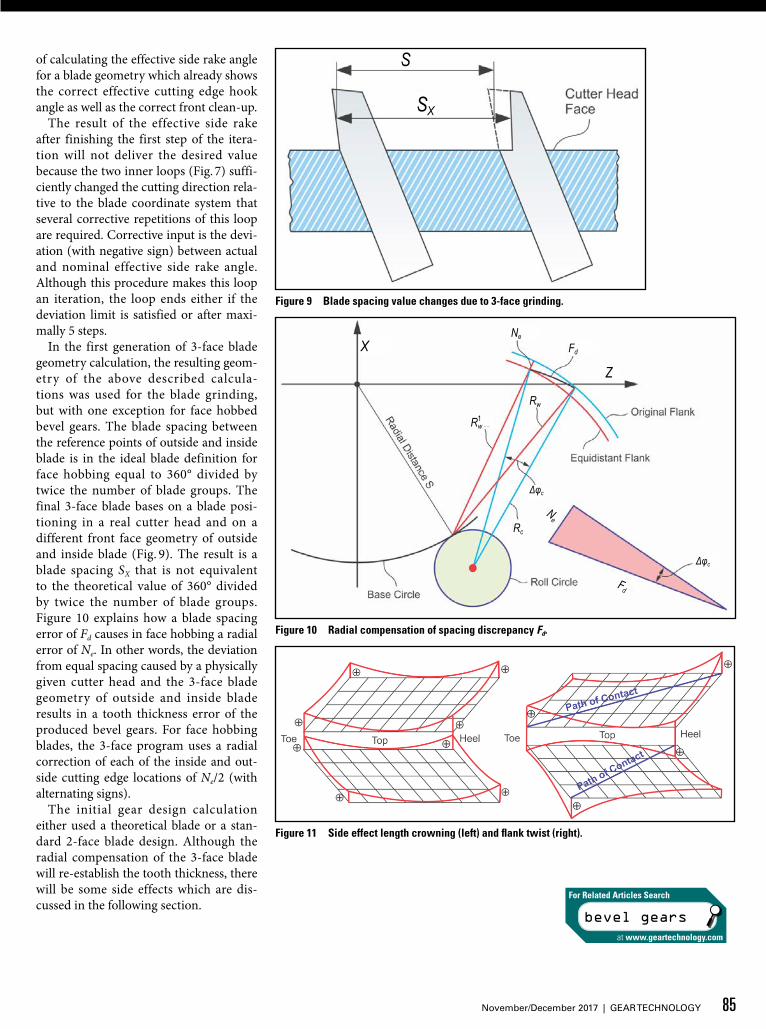
In the first generation of 3-face blade geometry calculation, the resulting geom-etry of the above described calcula-tions was used for the blade grinding, but with one exception for face hobbed bevel gears. The blade spacing between the reference points of outside and inside blade is in the ideal blade definition for face hobbing equal to 360° divided by twice the number of blade groups. The final 3-face blade bases on a blade posi-tioning in a real cutter head and on a different front face geometry of outside and inside blade (Fig. 9). The result is a blade spacing SX that is not equivalent to the theoretical value of 360° divided by twice the number of blade groups. Figure 10 explains how a blade spacing error of Fd causes in face hobbing a radial error of Ne. In other words, the deviation from equal spacing caused by a physically given cutter head and the 3-face blade geometry of outside and inside blade results in a tooth thickness error of the produced bevel gears. For face hobbing blades, the 3-face program uses a radial correction of each of the inside and out-side cutting edge locations of Ne/2 (with alternating signs).
The initial gear design calculation either used a theoretical blade or a stan-dard 2-face blade design. Although the radial compensation of the 3-face blade will re-establish the tooth thickness, there will be some side effects which are dis-cussed in the following section.
Figure 9 Blade spacing value changes due to 3-face grinding.
Figure 10 Radial compensation of spacing discrepancy Fd.
Figure 11 Side effect length crowning (left) and flank twist (right).
bevel gears
For Related Articles Search
at www.geartechnology.com
X
S
SX
Ne
Fd
Z
Fd
Rw
Rc
Ne
Δφc
Δφc
R1w
85November/December 2017 | GEAR TECHNOLOGY

Length Crowning and Flank Twist PhenomenonThe change from 2-face ground blades in Pentac-FH cutter heads to 3-face ground and all-around coated blades in PentacPlus-FH cutter heads also requires a relocation of the blade front faces, as described in the previous sec-tion. Different front relocations of outside and inside blades cause a tooth thickness change, which can be compensated with small changes of the inside blade and outside blade radii as mentioned above. The alteration of the blade point radii compared to the calculated values causes a major side effect which is a length crowning error on both flanks (Fig. 11, left). The second side effect relates to the change of the effective cutting edge hook angle versus the initial 2-face value (or theoretical blade definition) which results
in a flank twist (Fig.11, right).An effective possibility to reduce the
twist in the measurement result is to adjust the 3-face blade geometry closer to the standard 2-face blade geometry. This requires maintaining the original effec-tive cutting edge hook angle; however, the length crowning error still remains in the flank surfaces without any available correction freedoms.
Influence of Blade SteppingIf the outside and inside blades in a face hobbing cutter are built to equal height above the cutter head, then a degrada-tion of the tooth root geometry will occur if a gearset member has length crown-ing which is created by a cutter head tilt κ (Fig. 12). Figure 12 also aids in the understanding that if the lower outside blade was built to the same blade height
above the face of the cutter head as the upper inside blade, then the root of the work would be severely stepped between the two flanks. In order to eliminate the stepping in the work gear root fillet, a stepping between the outside and the inside blade height above the cutter head face is required.
The initial blade stepping calculation uses the length crowning tilt compo-nent and applies the objective to keep the blade tips within the vertical generating plane (Fig. 12). After the stepping amount in the direction of the cutter head axis is determined, the cutting edge tangent vector is used to calculate the precise, extended or shortened blade tip locations by maintaining the correct radius and offset at the blade reference point. The effective blades with their original calcu-lation point locations and their stepped blade tips (Fig. 12) are used in the gen-erating software to calculate the correct effective tooth slot and root fillet geom-etry.
The described blade stepping proce-dure will not influence the blade refer-ence point location and the geometry of the cutting edge surrounding surfac-es. The blade stepping merely extends or shortens the blade dedendum S890 (Fig. 12).
Blade Spacing Correction in TREFACE ProgramThe 3-face blade calculation program TREFACE applies the strategy to estab-lish the required cutter radii at the cal-culation point and define side rake and top rake angle correctly with respect to the relative cutting direction, given by the kinematic blade offset angle. While pro-viding the requested blade geometry, the program has to assure a sufficient front face cleanup, which has an influence on the resulting timing angle between the outside blade and the following inside blade. The initial timing angle φ (Fig. 13) is derived from the original 2-face cal-culation that is always exactly or close to 360° divided by twice the number of blade groups (which is the slot spacing angle of the cutter head). This original timing angle in connection with the orig-inal point radius adjustment in the 2-face calculation assures the cutting of the cor-rect tooth thickness.
Figure 12 Stepping calculation in blade software.
Figure 13 Cutting edge spacing φ.
Spacing ErrorΔφc = φc – φFd = Sx – s
86 GEAR TECHNOLOGY | November/December 2017[www.geartechnology.com]
technical

Three-face ground blades result in a spacing angle φx, which will — accord-ing to Figure 10 — lead to a tooth thick-ness error Ne. As previously mentioned in the section “Length Crowning and Flank Twist Phenomenon,” if the cor-rect tooth thickness is re-established with small cutter point radius changes, then a length crowning side effect of gears cut with such a cutter will occur that cannot be corrected without changes in blade geometry and alterations of the machine settings.
An uncommon solution was devel-oped, which achieves the correct blade spacing angle φ instead of φx (Fig. 13), and at the same time delivers the desired values for the effective cutting edge hook angle, the effective side rake angle, as well as providing a complete front face clean-up.
The new method is based on the idea that φx (Fig. 13) can be increased if the IB-blade receives a larger front clean-up thickness and φx can be reduced if the front clean-up thickness of the OB-blade is increased (Fig. 8). Only increasing of the front face clean-up thickness is per-missible because only then is the minimal clean-up preserved.
The algorithm of iterations and approximation loops in Figure 7 now becomes even more complex in order to achieve the desired goal of re-establishing the original blade spacing. Two addition-al outer loops have to be added (Fig. 14). The first added loop (loop No. 4) repeats all previously discussed calculation loops for both blades involved in cutting one pinion or gear slot (“Inside & Outside Blade Loop” in Fig. 14). The additional outer loop (Loop No. 5) will calculate the actual blade spacing angle (which required that both, IB- and OB-blade calculations have been finished at this point) and processes this value in order to decide which blade (inside or outside) has to receive what amount of additional front clean-up thickness ∆Sx. The cor-rective repetition of all four inner loops uses a dampened amount of ∆Sx (reduced amount). All inner loops are repeated as described in the section “Blade Parameter Definitions and Geometry Calculation.”
The outer blade spacing iteration loop repeats the calculations until the actually achieved blade spacing deviation from the original (desired) spacing is below a
defined iteration limit, or if the deviation value changes its sign (or it aborts after maximally 6 steps). The dampening fac-tor and the number of steps have been adjusted so that the overall system of loops works stably and the final results in all evaluated cases are within the accept-able accuracy limits (Fig. 15).
Figure 16 is the blade grinding sum-mary output section with the effective blade geometry. The highlighted yellow shows the effective cutting edge hook angle of 1.00° and the effective cutting side rake angle of 4.50°. Those are exact-ly identical with the input values of the TREFACE program where the correct val-ues have been achieved with one single run of TREFACE. The blade spacing was kept precisely at the value of the refer-ence cutter. In the output in Figure 16 the blade spacing correction is evident by the fact that the effective tip clean-up thick-ness of the outside blade varies by a large
Figure 14 Five imbedded loops for 3-face blade calculation.
Figure 15 Regaining of correct blade spacing.
S
87November/December 2017 | GEAR TECHNOLOGY

amount from the target value (2.47 mm versus 1.00 mm ).
Face milling designs do not require the outer iteration loop in Figure 14 because the tooth thickness is independent from the blade spacing.
A3F Feedback File to Create Relevant CMM-FileThe goal of a 3-face ground blade is to duplicate the theoretical blade geome-try used during flank form and tooth contact analysis development. This theo-retical blade has in all common cases a standard, 2-face geometry. The deci-
sion of which system is used (2-face or 3-face) and the decision of which par-ticular angles (especially the effective cutting edge hook angle) will be cho-sen for a 3-face blade geometry is made long after the original design calculation was conducted. In cases where the effec-tive cutting edge hook angle of a 3-face blade geometry deviate largely from the original 2-face blade, a specially calcu-lated feedback file (A3F-file) can be used to calculate the actual flank form of the gears that will be later manufactured with these blades (software function “create effective design”). The A3F-file contains
the effective 3-face blade geometry and is processed in the standard flank form generator.
The two possibilities to arrive at a coor-dinate file for 3-D flank form measure-ment are shown in the data flow and pro-cessing chart in Figure 17. It begins with the basic settings and basic blade geom-etry AAA-file or SPA-file. The standard case is the CMM-download file calcula-tion in CAGE, for example (Fig. 17, left). Parts cut with 2-face blades in a cutter head with 4.42° slot inclination are mea-sured directly with this CMM-download file (right pointing blue arrow to the cen-ter bottom graphic in Fig. 17).
In the case of 3-face ground blades used in a cutter head with 12° slot incli-nation to cut a bevel gear, it is possible to use the parallel generated A3F-file with the effective blade geometry and go the path to generate the CMM-effective geometry calculation (Fig. 17, right) and measure the parts with this coordinate file (left pointing blue arrow to center bottom graphic in Fig. 17).
In cases where the post-revision 3-face blade calculation is used, and if the effec-tive blade hook angle is between -1° and +1°, then the manufactured bevel gears can be directly measured with the stan-dard CMM-download file (calculated for 2-face blades in a cutter with 4.42° slot inclination) which is indicated with the red arrow (Fig. 17).
Example Results: Pre- and Post-Revision SoftwareIn order to judge the cutting results after the software revision, some baseline cal-culations have been made and will be dis-cussed in the following paragraph. All measurement results in this section result from blades ground on the same BPG blade grinder which have been used to cut sample pinions on the same Phoenix cutting machine by utilizing a cutter head with 4.42° slot inclination and a cutter head with 12° blade inclination. The “sum-of-errors-squared” is defined as the sum-mation of the squared deviation amounts of all 90 surface grid points (of both flanks, measuring a 9 × 5 grid). Per con-vention, the unit “inch²” is used — even if the surface evaluation is done in metric units, as in the present case.
The flank form measurement results in Figure 18 are the baseline for a pinion
Figure 17 Two-face vs. three-face nominal CMM data file.
Figure 16 Effective blade geometry output in program TREFACE.
88 GEAR TECHNOLOGY | November/December 2017[www.geartechnology.com]
technical

cut with a 2-face ground blade built in a cutter head with 4.42° slot inclination and measured with the standard CAGE download file, which is also based on a 2-face blade in a cutter with 4.42° slot inclination. The corner point deviation of less than 4 μm (Fig. 18) lead to a sum-of-errors-squared of 0.000 000 40 inch2, which is an excellent result for cutting before heat treatment.
The second baseline measurement also uses the standard CAGE download file, but the measured pinion was cut with a 3-face ground blade that was built in a cutter head with 12° slot inclination; the blade grinding summary for this test had been calculated with the pre-revi-sion software. Figure 19 shows the devia-tions of the cut pinion, which are near-ly 14 μm. The sum-of- errors-squared is 0.000 00 231 inch², which is still accept-able for a soft cut pinion before heat treatment. However, the surface devia-tions are significantly larger than the ones in Figure 18. The 3-face blade geome-try featured 4.5° effective side rake angle and 1° effective cutting edge hook angle, which compares to the 2-face blades with side rake angles of 12° and effective cut-ting edge hook angles between +1° and -1°. In particular the effective cutting edge hook angle causes the flank sur-face twist, visible on the concave flank (Fig. 19). The ∆RW blade point radii cor-rection that was used in the pre-revision software to maintain the correct tooth thickness causes the length crowning, which is more visible on the convex flank.
As a first step to represent the 3-face blade geometry and subsequently the flank geometry of the manufactured gears, a file that contains the effective blade geometry was created (so-called A3F-file). The same 3-face cut pinion measured before with the standard CAGE download file (Fig. 19) was also measured with a download file generated with the new A3F-file. The results of this mea-surement are shown (Fig. 20). This mea-surement achieved a sum-of-errors-squared of 0.000 000 20 inch², with cor-ner point deviations in the single micron range — an excellent result.
However, the intention of using 3-face blades is the improvement of the cutting conditions without changing the initial-ly developed flank surfaces. If the A3F-file was used to re-run the tooth con-
tact analysis, then small changes in the path of contact bias direction, as well as changes in the length crowning amount, could be observed.
The development goal of the revised TREFACE software was to eliminate or reduce any differences between 2-face
and 3-face blades and subsequently elimi-nate the differences between cutter heads with different slot inclination.
It became evident during a theoreti-cal study of the cause of flank twist and length crowning that side rake angle and top rake angle are only indirect parame-
Figure 18 Standard CAGE download file, part cut with 4.42° cutter slot inclination and 2-face blade.
Figure 19 Standard CAGE download file, part cut with 12° cutter slot inclination and 3-face blade with blade calculation before software revision.
Figure 20 A3F download file, part cut with 12° cutter slot inclination and 3-face blade.
89November/December 2017 | GEAR TECHNOLOGY

ters with limited significance to the flank twist. The investigations resulted in the acknowledgement that the effective cut-ting edge hook angle is the sole blade fea-ture causing the flank surface twist. And yet the theoretical investigations and the verification in practical cutting trials also showed that the flank twist is minimized if the effective cutting edge hook angle is selected between 0° and +1°.
The addition of the two outer calcu-lation loops (Fig. 14) with the strategy of increasing one of the front clean-up depths (either on the inside blade or on the outside blade) resulted in a 3-face blade spacing that duplicated precise-ly the original 2-face reference blade. Calculations with the post-revision TREFACE program in connection with an input value for the effective cutting edge hook angle between 0° and +1° deliver new-generation 3-face blades that eliminate all length crowning errors and reduce about 85% of the flank twist expe-rienced with the pre-revision software.
Practical proof of this is shown in the flank deviation graphic (Fig. 21). The 3-face blade calculation was repeated with the post-revision TREFACE pro-gram. As input for the effective hook angle values of inside and outside blade, the recommendation above was applied. Pinions manufactured with the new 3-face blade geometry in a cutter head with 12° slot inclination angle are mea-sured with the standard CAGE down-load file (based on 2-face blades with 12° blade side rake angle used in a cut-ter with 4.42° slot inclination) result in a single micron flank form deviation with an excellent sum-of-errors-squared of 0.000 000 46 inch².
In face hobbing the cutting edge hook angle — as well as the spacing between outside and inside blades — has an influ-ence on the flank geometry of the man-ufactured bevel gears. In an industrial environment the basic blade geometry (reference blade) is defined with the orig-inal job design early on, but the deci-sion “2-face or 3-face blades” is made much later in the process. Manufacturers were not comfortable with the fact that their decision to use 3-face ground blades could change the flank geometry development of their already approved designs. This was the reason for a major revision of the Gleason blade summary
calculation program TREFACE.Three-face blades ground with sum-
maries calculated with the post-revision TREFACE software do not create length crowning differences, compared to the 2-face reference blade. All flank twist or bias differences between gears cut with 3-face blades versus the 2-face refer-ence blade can be eliminated, or great-ly reduced, if the effective cutting edge hook angle is chosen between 0° and 1°. The new calculation allows the user to make the decision to use cutters with slot inclinations higher than the reference cutter in connection with 3-face ground blades much later than the development of the gearset design. This enables a man-ufacturer to develop and manufacture in different location without the poten-tial of discrepancies between desired and achieved flank geometry. It also makes manufacture of the same gearset design possible in different locations without noticeable differences.
In cases where a manufacturer likes to apply an effective cutting edge hook angle that is several degrees away from the rec-ommendation, a certain flank surface twist in the manufactured parts versus the original development (and the standard CAGE download file) will occur. This problem can be resolved by utilizing the A3F-file with the effective blade geometry. A tooth contact analysis using the A3F-file will confirm that Ease-Off and tooth contact still reflect the original devel-opment, or will show that fine tuning is required in order to adjust the 3-face gen-erated (and manufactured) gearsets to the original development. In either case, a download file generated with the basic
data of the A3F-file (no standard CAGE download file) has to be utilized for the coordinate measurement.
References1. Stadtfeld, H.J. Gleason Bevel Gear
Technology — the Science of Gear Engineering and Modern Manufacturing Methods for Angular Transmissions, Gleason Publication, ISBN 978-0-615-96492-8, 2014.
2. Stadtfeld, H.J. Stick Blade Definition Manual, Gleason Company Publication, Rochester, New York, Feb. 2014.
3. Stadtfeld, H.J. The New Freedoms-Multi-Face Ground Bevel Gear Cutting Blades, Gleason Company Publication, Rochester, New York, June 2010.
Dr. Hermann J. Stadtfeld received in 1978 his B.S. and in 1982 his M.S. in mechanical engineering at the Technical University in Aachen, Germany; upon receiving his Doctorate, he remained as a research scientist at the University’s Machine Tool Laboratory. In 1987, he accepted the position of head of engineering and R&D of the Bevel Gear Machine Tool Division of Oerlikon Buehrle AG in Zurich and, in 1992, returned to academia as visiting professor at the Rochester Institute of Technology. Dr. Stadtfeld returned to the commercial workplace in 1994 — joining The Gleason Works — also in Rochester — first as director of R&D, and, in 1996, as vice president R&D. During a three-year hiatus (2002–2005) from Gleason, he established a gear research company in Germany while simultaneously accepting a professorship to teach gear technology courses at the University of Ilmenau. Stadtfeld subsequently returned to the Gleason Corporation in 2005, where he currently holds the position of vice president, bevel gear technology and R&D. A prolific author (and frequent contributor to Gear Technology), Dr. Stadtfeld has published more than 200 technical papers and 10 books on bevel gear technology; he also controls more than 50 international patents on gear design,
gear process, tools and machinery.
Figure 21 Standard CAGE download file, part cut with 12° cutter slot inclination and 3-face blade with bade calculation after software revision.
90 GEAR TECHNOLOGY | November/December 2017[www.geartechnology.com]
technical