Boiler & Auxiliaries Maintenance Manuall Qn1 Sec g 04 Tp 009
Upload
bui-vanluongCategory
view
94download
6
SEC
QUANG NINH THERMAL POWER JOINT STOCK COMPANY 2×300 MW
TURBINE & AUXILIARIES MAINTENANCE MANUAL
Date: 2008-10-20 No.:QN1-SEC-G-04-TP-010 Rev. : A
1
QUANG NINH THERMAL POWER JOINT STOCK COMPANY
2 × 300 MW – Anthracite Coal Fired Power Station
Turbine & Auxiliaries
Maintenance Manual
SEC
QUANG NINH THERMAL POWER JOINT STOCK COMPANY 2×300 MW
TURBINE & AUXILIARIES MAINTENANCE MANUAL
Date: 2008-10-20 No.:QN1-SEC-G-04-TP-010 - 1 - Rev. : A
- 1 -
INDEX
1 MAIN TECHNOLOGICAL SPECIFICATION AND CONFIGURATION OF TURBINE ...................- 1 -
1.1 SUMMARIZE ............................................................................................................................................... - 1 - 1.2 TECHNICAL SPECIFICATIONS AND THERMAL PARAMETERS ........................................................................ - 1 - 1.3 MAIN TECHNICAL DATA............................................................................................................................. - 2 - 1.4 TURBINE STRUCTURE................................................................................................................................. - 3 - 1.4.1 STEAM INLET CHAMBER ......................................................................................................................... - 3 - 1.4.2 HP, IP & LP CASING ............................................................................................................................... - 3 - 1.4.3 ROTOR .................................................................................................................................................... - 4 - 1.4.4 BEARING................................................................................................................................................. - 4 - 1.4.5 LUBRICATION OIL TANK.......................................................................................................................... - 4 - 1.4.6 TURNING GEAR....................................................................................................................................... - 4 - 1.5 THERMAL SYSTEM ..................................................................................................................................... - 5 - 1.6 TURBINE CONTROL SYSTEM ...................................................................................................................... - 5 - 1.6.1 SOLID STATE ELECTRONIC CONTROLLER................................................................................................ - 5 - 1.6.2 STEAM VALVE ACTUATOR....................................................................................................................... - 5 - 1.6.3 EH OIL SUPPLY SYSTEM ......................................................................................................................... - 5 - 1.6.4 EMERGENCY TRIP SYSTEM...................................................................................................................... - 6 -
2 TURBINE PROPER ......................................................................................................................................- 6 -
2.1 MAINTENANCE OF TURBINE CASING.......................................................................................................... - 6 - 2.2 STATIC CARRIER RING AND BALANCE PISTON CARRIER RING ................................................................ - 10 - 2.3 MAINTENANCE OF GLAND STEAM AND SHAFT SEALING SYSTEM............................................................ - 12 - 2.4 MAINTENANCE OF SLIDING PIN SYSTEM.................................................................................................. - 16 - 2.5 MAINTENANCE OF TURBINE ROTOR......................................................................................................... - 18 - 2.6 MAINTENANCE OF SHAFTING................................................................................................................... - 20 - 2.7 MAINTENANCE OF BEARING AND TURNING GEAR ................................................................................... - 23 - 2.8 CYLINDER BOX-UP .................................................................................................................................. - 33 -
3 MAINTENANCE DESCRIPTION OF STEAM INLET VALVES..........................................................- 36 -
3.1 MAINTENANCE OF HP MAIN STOP VALVE................................................................................................ - 36 - 3.2 MAINTENANCE OF HP CONTROL VALVE .................................................................................................. - 40 - 3.3 MAINTENANCE OF REHEAT STEAM MAIN STOP VALVE........................................................................... - 42 - 3.4 INSPECTION OF REHEAT CONTROL VALVE............................................................................................... - 45 -
4. INSPECTION OF INSPECTION, PROTECTION AND OIL SYSTEM ..............................................- 47 -
4.1 INSPECTION OF MAIN OIL PUMP .............................................................................................................. - 47 - 4.2 INSPECTION OF EMERGENCY GOVERNOR................................................................................................. - 47 - 4.3 MAINTENANCE OF AC & DC LUBRICATION OIL PUMP............................................................................ - 48 -
SEC
QUANG NINH THERMAL POWER JOINT STOCK COMPANY 2×300 MW
TURBINE & AUXILIARIES MAINTENANCE MANUAL
Date: 2008-10-20 No.:QN1-SEC-G-04-TP-010 - 2 - Rev. : A
- 2 -
4.4 MAINTENANCE OF JACK OIL PUMP .......................................................................................................... - 50 - 4.5 MAINTENANCE OF MAIN OIL TANK AND OIL COOLER............................................................................. - 53 - 4.5.1 MAINTENANCE OF MAIN OIL TANK .................................................................................................... - 53 - 4.5.2 OIL COOLER ....................................................................................................................................... - 54 - 4.6 MAINTENANCE OF STANDBY SEALING OIL PUMP .................................................................................... - 55 - 4.7 DEH CONTROL SYSTEM .......................................................................................................................... - 57 - 4.7.1 INSPECTION OF DEH CONTROL SYSTEM STRUCTURE ........................................................................... - 57 - 4.7.2 MAINTENANCE OF EH OIL TANK .......................................................................................................... - 60 - 4.7.3 MAINTENANCE OF HP ACCUMULATOR.................................................................................................. - 61 -
5 MAINTENANCE OF ELECTRIC BOILER FEED PUMP ....................................................................- 63 -
5.1GENERAL.................................................................................................................................................. - 63 - 5.1.1 ELECTRIC FEED PUMP........................................................................................................................... - 63 - 5.1.2 BOOSTER PUMP..................................................................................................................................... - 64 - 5.1.3 HYDRAULIC COUPLING......................................................................................................................... - 65 - 5.2 BASIC PARAMETERS OF FEED PUMP......................................................................................................... - 65 - 5.3 MAINTENANCE OF BOOSTER PUMP .......................................................................................................... - 66 - 5.4 MAINTENANCE OF FEED PUMP................................................................................................................. - 74 - 5.5 MAINTENANCE OF HYDAULIC COUPLING ................................................................................................ - 86 -
6 AUXILIARY EQUIPMENTS .....................................................................................................................- 92 -
6.1 MAINTENANCE OF CONDENSER ............................................................................................................... - 92 - 6.2 MAINTENANCE OF CONDENSATE WATER PUMP........................................................................................ - 95 - 6.3 MAINTENANCE OF CLOSED AND OPEN COOLING WATER PUMP ............................................................... - 98 - 6.4 MAINTENANCE OF WATER RING VACUUM PUMP.................................................................................... - 101 - 6.5 MAINTENANCE OF CIRCULATING PUMP ................................................................................................. - 104 - 6.6 MAINTENANCE OF HIGH PRESSURE HEATER.......................................................................................... - 113 - 6.7 MAINTENANCE OF LOW PRESSURE HEATER........................................................................................... - 116 -
7 VALVE MAINTENANCE......................................................................................................................... - 117 -
7.1 GENERAL REQUIREMENT OF VALVE MAINTENANCE ............................................................................. - 117 - 7.2 MAINTENANCE OF GATE VALVE OF HIGH PRESSURE SELF-SEALING ..................................................... - 118 - 7.2.1 MAINTENANCE OF HIGH PRESSURE GLOBE VALVE ............................................................................. - 120 - 7.2.2 MAINTENANCE OF SAFETY VALVE ...................................................................................................... - 122 - 7.2.3 MAINTENANCE OF BUTTERFLY VALVE ................................................................................................ - 123 - 7.2.4 MAINTENANCE OF CHECK VALVE ....................................................................................................... - 125 - 7.2.5 MAINTENANCE OF EXTRACTION CHECK VALVE.................................................................................. - 127 - 7.2.6 MAINTENANCE OF PNEUMATIC STEAM TRAP VALVE........................................................................... - 129 - 7.2.7 MAINTENANCE OF HP WATER INLET THREE-WAY VALVE ................................................................... - 130 - 7.2.8 MAINTENANCE OF BFP RECIRCULATION VALVE ................................................................................. - 132 - 7.2.9 MAINTENANCE OF OTHER VALVES...................................................................................................... - 133 -

SEC
QUANG NINH THERMAL POWER JOINT STOCK COMPANY 2×300 MW
TURBINE & AUXILIARIES MAINTENANCE MANUAL
Date: 2008-10-20 No.:QN1-SEC-G-04-TP-010 - 1 - Rev. : A
1 Main Technological Specification and Configuration of Turbine
1.1 Summarize
The turbine of Vietnam Quang Ninh Thermal Power Plant, which is domestically produced by introduce technique, is a kind of condensing steam turbine with the features of 300MW sub-critical, reheat, tandem, double cylinder, double-flow. It is applied with digital electro-hydraulic regulating system, manufactured by Shanghai Turbine Works introducing the technique of Westinghouse Electric Company LLC. Its rated steam admission parameter is 16.7MPa/538℃/538℃ accompanied with 8 level recuperative & extraction steam.
The HP&IP turbine is impulse & reaction mixed type, whose HP&IP section is supplied with combined casing countercurrent structure; the LP cylinder is applied with three layer cylinder structure with double current reaction type. This turbine type basicly belongs to the reaction type and its through flow section includes 35 level in total, of which the HP section consist of 1 uniserial velocity stage and 11 pressure stage, the MP section of 9 pressure stage and LP section (2×7)pressure stage, associated with 1025t/h sub-critical, reheat, forced circulation steam drum boiler, as well as water-hydrogen-hydrogen cooling generator. Both boiler & turbine thermal system adopts the unit arrangement.
Main machine oil system is equipped with embedded type oil pipeline and composite type oil tank, and the HP oil pipe and lubricating oil pipe shall be concentrated-welded in the protection casing, its lubricating oil use the #32 turbine oil. The turbine generator unit consist of 7 bearing liner, of which the #1 & #2 bearing of turbine body applied with 4 pieces of tilting type liner, the #3 bearing be 3 pieces, the #4 bearing be spool tile structure, the generator is equipped with 2 pieces of spool tile, exciter be 1 of spool tile, both LP #3 & #4 bearing be head shaft oil device and at the #4 tile position is equipped with engine turning gear.
This machine control system is composed of two parts: EH oil supply and control part, the control part consists of hydraulic actuator on the steam valve, a emergency trip control block and solenoid valve, a EH oil test block component, a oil drive control pilot valve, a diaphragm valve with contact function as well as electronic controller. The EH oil supply part can supply oil and pressure for control part, which is composed of a oil tan with oil cooler, oil cooler, HP accumulator, LP accumulator, variety pressure control valve, oil pump and motor.
The bypass system, which is divided into two parts of HP bypass and LP bypass, is the electric drive turbine bypass control system produced by Shanghai Electric Power Company.
The feed water & regenerative heat system is applied with 8 heaters including 3 HP heaters, 1 deaerator, 4 LP heaters. All HP & LP heater belongs to surface type, 3 HP heaters equipped with superheated steam cooling, every heater is tandem arrangement, and water drain is cascade flow automatically without the drain valve.
1.2 Technical Specifications and Thermal Parameters
Items Main Equipment Specifications
Type Sub-critical, Intermediate-reheat, Combined HP&IP Casing, Double-shell, Dual-exhaust, Single-shaft, Condensing
Model N300—16.7/538/538
Turning Clockwise direction deemed from turbine end to generator end
Regenerative Stages Three (3) HP Heaters, Four (4) LP Heaters, One (1) Deaerator
SEC
QUANG NINH THERMAL POWER JOINT STOCK COMPANY 2×300 MW
TURBINE & AUXILIARIES MAINTENANCE MANUAL
Date: 2008-10-20 No.:QN1-SEC-G-04-TP-010 - 2 - Rev. : A
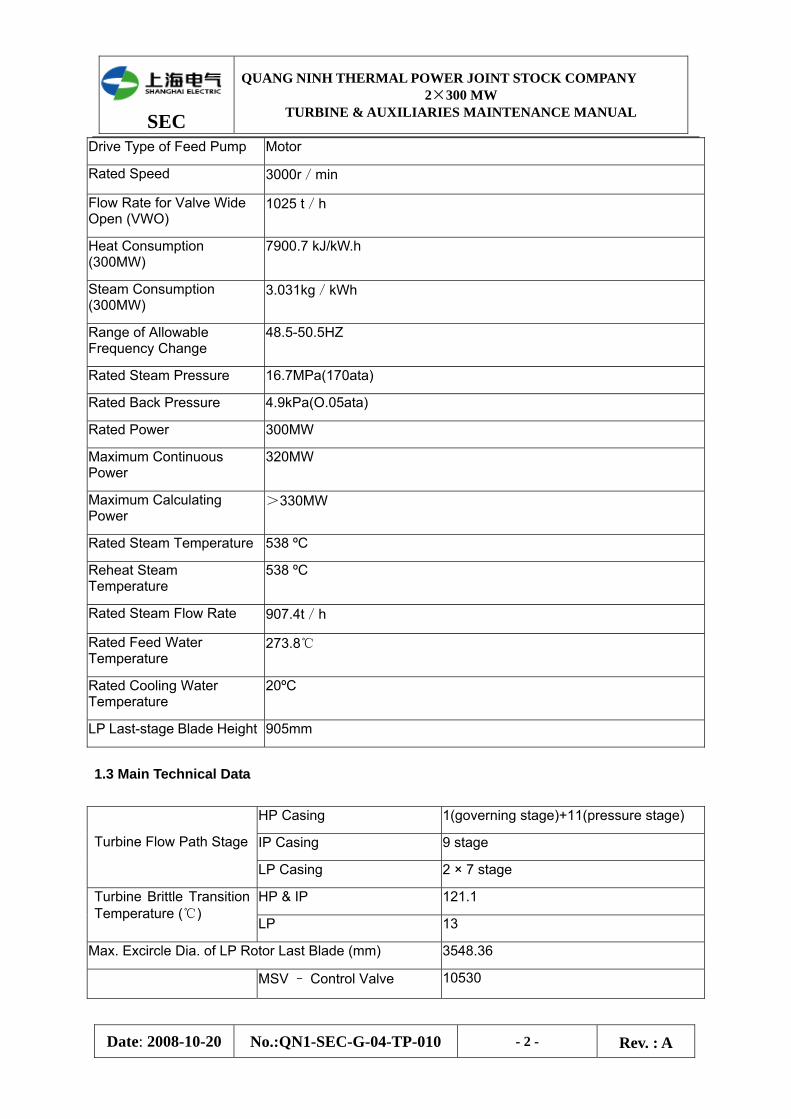
Drive Type of Feed Pump Motor
Rated Speed 3000r/min
Flow Rate for Valve Wide Open (VWO)
1025 t/h
Heat Consumption (300MW)
7900.7 kJ/kW.h
Steam Consumption (300MW)
3.031kg/kWh
Range of Allowable Frequency Change
48.5-50.5HZ
Rated Steam Pressure 16.7MPa(170ata)
Rated Back Pressure 4.9kPa(O.05ata)
Rated Power 300MW
Maximum Continuous Power
320MW
Maximum Calculating Power
>330MW
Rated Steam Temperature 538 ºC
Reheat Steam Temperature
538 ºC
Rated Steam Flow Rate 907.4t/h
Rated Feed Water Temperature
273.8℃
Rated Cooling Water Temperature
20ºC
LP Last-stage Blade Height 905mm
1.3 Main Technical Data
HP Casing 1(governing stage)+11(pressure stage)
IP Casing 9 stage
Turbine Flow Path Stage
LP Casing 2 × 7 stage
HP & IP 121.1 Turbine Brittle Transition Temperature (℃)
LP 13
Max. Excircle Dia. of LP Rotor Last Blade (mm) 3548.36
MSV – Control Valve 10530
SEC
QUANG NINH THERMAL POWER JOINT STOCK COMPANY 2×300 MW
TURBINE & AUXILIARIES MAINTENANCE MANUAL
Date: 2008-10-20 No.:QN1-SEC-G-04-TP-010 - 3 - Rev. : A
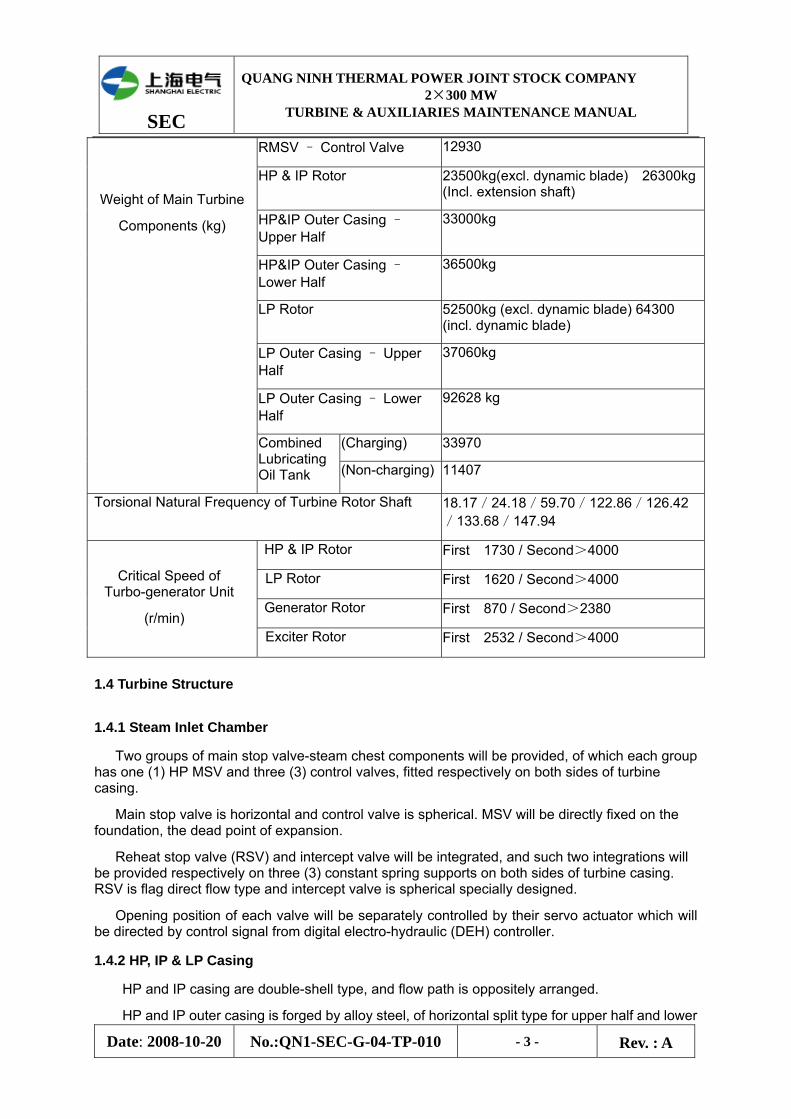
RMSV – Control Valve 12930
HP & IP Rotor 23500kg(excl. dynamic blade) 26300kg (Incl. extension shaft)
HP&IP Outer Casing – Upper Half
33000kg
HP&IP Outer Casing – Lower Half
36500kg
LP Rotor 52500kg (excl. dynamic blade) 64300 (incl. dynamic blade)
LP Outer Casing – Upper Half
37060kg
LP Outer Casing – Lower Half
92628 kg
(Charging) 33970
Weight of Main Turbine
Components (kg)
Combined Lubricating Oil Tank (Non-charging) 11407
Torsional Natural Frequency of Turbine Rotor Shaft 18.17/24.18/59.70/122.86/126.42/133.68/147.94
HP & IP Rotor First 1730 / Second>4000
LP Rotor First 1620 / Second>4000
Generator Rotor First 870 / Second>2380
Critical Speed of Turbo-generator Unit
(r/min) Exciter Rotor First 2532 / Second>4000
1.4 Turbine Structure
1.4.1 Steam Inlet Chamber
Two groups of main stop valve-steam chest components will be provided, of which each group has one (1) HP MSV and three (3) control valves, fitted respectively on both sides of turbine casing.
Main stop valve is horizontal and control valve is spherical. MSV will be directly fixed on the foundation, the dead point of expansion.
Reheat stop valve (RSV) and intercept valve will be integrated, and such two integrations will be provided respectively on three (3) constant spring supports on both sides of turbine casing. RSV is flag direct flow type and intercept valve is spherical specially designed.
Opening position of each valve will be separately controlled by their servo actuator which will be directed by control signal from digital electro-hydraulic (DEH) controller.
1.4.2 HP, IP & LP Casing
HP and IP casing are double-shell type, and flow path is oppositely arranged.
HP and IP outer casing is forged by alloy steel, of horizontal split type for upper half and lower
SEC
QUANG NINH THERMAL POWER JOINT STOCK COMPANY 2×300 MW
TURBINE & AUXILIARIES MAINTENANCE MANUAL
Date: 2008-10-20 No.:QN1-SEC-G-04-TP-010 - 4 - Rev. : A
half, and the lower half casing is supported by four bending claws upward integrated forged with casing end, and the direction of claw bearing face will be same with that of casing split surface.
Separated HP and IP inner casing is also forged by alloy steel, of horizontal split type for upper half and lower half. On the horizontal split joint, the inner casing will be placed on outer casing with locating pins fixed at top and bottom to maintain correctness of turbine axial line, and to allow free expansion and contraction as temperature changed.
LP casing will be composed of one (1) outer casing, two (2) inner casings and thermal enclosure, and the differential temperature from steam inlet to condenser will be distributed by three (3) walls.
LP outer and inner casing is of welded type, outer casing being vertically split, and both casings are separated to be upper half and lower half on horizontal split. Steam will come in at center and flow to various sides, and then flow downwards to steam exhaust and enter condenser.
1.4.3 Rotor
HP and IP rotor is integrally manufactured with alloy metal forging (30CrlMo1V), and connected to steam inlet terminal by one short shaft fixing by bolt, forming a thrust collar installed with main oil pump impeller and emergency governor.
LP rotor is also manufactured with alloy metal forging (30Cr2Ni4MoV). Integral rotor shall go through hot-box device test and accurate dynamic balance test after all blades installed and processing completed.
HP&IP casing will be connected with LP casing by rigid flange coupling. Such rotator unit formed will be axially posited by HP & IP rotor thrust collar and thrust bearing. LP rotor will be connected with generator rotor through intermediate shaft by rigid flange coupling one by one, and turning gear is provided between intermediate shaft and generator coupling. So, main rotary units therefore formed (incl. HP and IP rotor, LP rotor and generator rotor, exciter rotor, etc.) will be supported on sever (7) bearings.
1.4.4 Bearing
Turbine has four (4) radial bearing with two (2) for HP & IP rotor and two (2) for LP rotor. Two (2) HP&IP bearings are of tilting pad radial bearing. LP front bearing is of tilting pad type for lower half, and column type for upper half, and LP rear bearing is of column type. Thrust bearing is of Babbitt alloy structure, six (6) thrust pads in front and rear, automatically keeping even load on each pad in operation. Generator has two (2) bearings an exciter has one (1).
1.4.5 Lubrication Oil Tank
Lubrication oil tank is a combined oil tank of volume approx. 26.5m3. Oil system members are oil injector, AC/ DC oil pump, demister, smoke exhauster.
Air fan and spare HP sealing oil pump are all installed in the said system, and whole oil tank shall be of compacted structure. Oil tank shall have electric heater for warming lubrication oil at startup. Lubrication oil piping is of sleeve type. HP oil piping will be covered by oil returning piping to avoid any possible oil leakage in control room for safety purpose.
1.4.6 Turning Gear
Turning gear is used for rotor turning at low speed in turbine startup and shut-down phase, so as to enable rotor receive even heating and cooling and to minimize the deflection caused by uneven rotor temperature.
Turning gear will be fixed on bearing seat at LP casing terminal of generator side, driven by 30kW motor, moved by sprocket, worm gear and double-reduction rear, as well as bull gear
SEC
QUANG NINH THERMAL POWER JOINT STOCK COMPANY 2×300 MW
TURBINE & AUXILIARIES MAINTENANCE MANUAL
Date: 2008-10-20 No.:QN1-SEC-G-04-TP-010 - 5 - Rev. : A
between driving turbine and generator coupling, to achieve rotor speed aprrox. 2.51r/min. Pinion shaft and gear bush will be made of porous bronze containing polyvinyl fluoride, not need lubrication.
1.5 Thermal System
New steam will go through MSV first, then control valve, and last flow into HP casing for doing work. Control valve will control the steam flow rate in HP casing. Such steam will go through three (3) ducts connected with steam inlet bushing on casing upper half and another three (3) ducts connected with inlet bushing on casing lower half, and each bushing will be connected with a nozzle chamber by sliding connector.
After doing work by expansion in HP casing, steam will flow from exhaust outlet on the lower of outer casing to boiler reheater, and reheat steam will pass through IP MSV and control valve, and flow into IP casing for doing work. IP control valve outlet will connect with steam inlet chamber of lower IP casing by sliding connector. Steam, finishes doing work by expansion in IP casing, will pass through cross-over pipe and enter in the center of LP flow path, go to exhaust outlets at both terminals and flow into condenser.
Extraction outlet will be set on each turbine casing. Steam extracted from first stage outlet after turbine 7 stage being supplied for HP heater no.1; that from second outlet after turbine 11 stage for HP heater no.2 and auxiliary purpose; that from third outlet after turbine 16 for HP heater no.3; that from fourth outlet after turbine stage 20 for deaerator and other auxiliary purpose; that from fifth outlet after turbine stage 22 (control valve end) for LP heater no.5; that from sixth outlet after turbine stage 31 (end of generator) for LP heater no.5; that from seventh outlet after turbine stage 25/32 for LP heater no.7; and that from eighth outlet after turbine stage 26/33 for LP heater no.8.
1.6 Turbine Control System
Control system of this unit will adopt digital electro-hydraulic (DEH) control system for two purposes: turbine speed governing and turbine load control. Control system consists of five parts as follows:
1.6.1 Solid State Electronic Controller
Electronic controller will process basic calculation of setting value of speed or load and calculation of turbine feedback signals, and send output signal for controlling various steam valve servo actuators. The hardware of this controller will consist of one (1) set of digital computer with magnetic core memory and one (1) set of printed circuit card of module set on the frame.
1.6.2 Steam Valve Actuator
Position of steam valve will be controlled by their own actuator. Such actuator will consist of a hydraulic oil tank whose opening will be driven by EH oil pressure and closing by spring force, the oil tank will be connected with one control block on which isolation valve, quick unloading valve and check valve are fixed.
1.6.3 EH Oil Supply System
EH oil supply system is to supply EH oil for driving of servo actuator, so as to govern opening of various steam valves. EH oil is a type triaryl-phosphate grease, with good performance of fire-resistance and fluid stability.
Oil discharged from EH oil pump will go through oil filter, unloading valve, check valve and oil overflow valve fixed on control block, and enter HP header and accumulator. Unloading valve will interconnect the oil pump outlet with accumulator and HP header, and supply oil to system in normal pressure 14.47MPa. Check valve on piping can prevent EH oil return. Over-pressure valve
SEC
QUANG NINH THERMAL POWER JOINT STOCK COMPANY 2×300 MW
TURBINE & AUXILIARIES MAINTENANCE MANUAL
Date: 2008-10-20 No.:QN1-SEC-G-04-TP-010 - 6 - Rev. : A
on HP header can prevent over high pressure in EH oil system. In case oil pressure increases to 15.85-16.2MPa, the oil on outlet will flow into oil tank.
EH return oil will be led to oil cooler by a directional control valve and flow into oil tank.
1.6.4 Emergency Trip System
Emergency governor shall have one mechanical over speed protection bolt and one trip handle hand-operated at site, any action of one of them will release mechanical-manual governing oil and make diaphragm unable to achieve upper oil pressure, and open the diaphragm valve under spring force, release EH governing oil and therefore shut down the unit. Mechanical-manual governing oil and EH governing oil will not be interconnected.
Emergency governing block posited in front bearing pedestal shall have six (6) solenoid valves, four (4) of which are automatic shutdown governing solenoid valve 20/AST. In normal operation, they will close subject to excitation, and therefore the oil release path of EH governing oil in automatic shutdown governing manifolds is closed and oil pressure of lower piston of steam valve actuator; when the solenoid valve open subject to power supply failure, the EH governing oil in manifold will be released and the said lower oil pressure will be disappeared, and steam valve closed and unit shut down. 20/AST solenoid valve adopt arrangement in parallel and series for multi-protection purpose. At least one solenoid valve in the flow path must be opened for unit shutdown.
Pressure switch and sensor causing shut down include: overlow of bearing oil pressure, overlow of EH oil pressure, overhigh wearing of thrust bearing, overlow of condenser vacuum, overspeed and shutdown by one user.
The rest two solenoid valves are overspeed protection governor solenoid valve 20/OPC. They are governed by DEH controller and OPC protection part, arranged in series. In normal condition, these two valves will be closed by excitation, so release path of oil flow in OPC manifold be closed, and oil pressure of lower piston of HP & IP control valve actuator be acquired. In case unit speed is up to 103% of rated speed, OPC behaves and these two valves above said will open subject to power supply failed, oil liquid in OPC manifold be released, quick unloading valve of control valve actuator be opened, and such actuators will be closed quickly subject to oil pressure of lower pison being eliminated. In case unit speed is reduced to rated speed, these two solenoid valve will be closed by excitation and control valve will be opened again, and unit speed will be controlled by main steam control valve.
Check valve between automatic shutdown emergency governing oil circuit and OPC oil circuit will be used to maintain the oil pressure in oil circuit when OPC behaves.
2 Turbine Proper
2.1 Maintenance of Turbine Casing
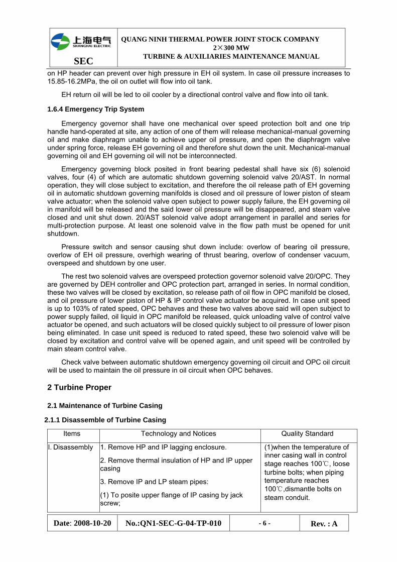
2.1.1 Disassemble of Turbine Casing
Items Technology and Notices Quality Standard
I. Disassembly
1. Remove HP and IP lagging enclosure.
2. Remove thermal insulation of HP and IP upper casing
3. Remove IP and LP steam pipes:
(1) To posite upper flange of IP casing by jack screw;
(1)when the temperature of inner casing wall in control stage reaches 100℃, loose turbine bolts; when piping temperature reaches 100℃,dismantle bolts on steam conduit.
SEC
QUANG NINH THERMAL POWER JOINT STOCK COMPANY 2×300 MW
TURBINE & AUXILIARIES MAINTENANCE MANUAL
Date: 2008-10-20 No.:QN1-SEC-G-04-TP-010 - 7 - Rev. : A
Items Technology and Notices Quality Standard
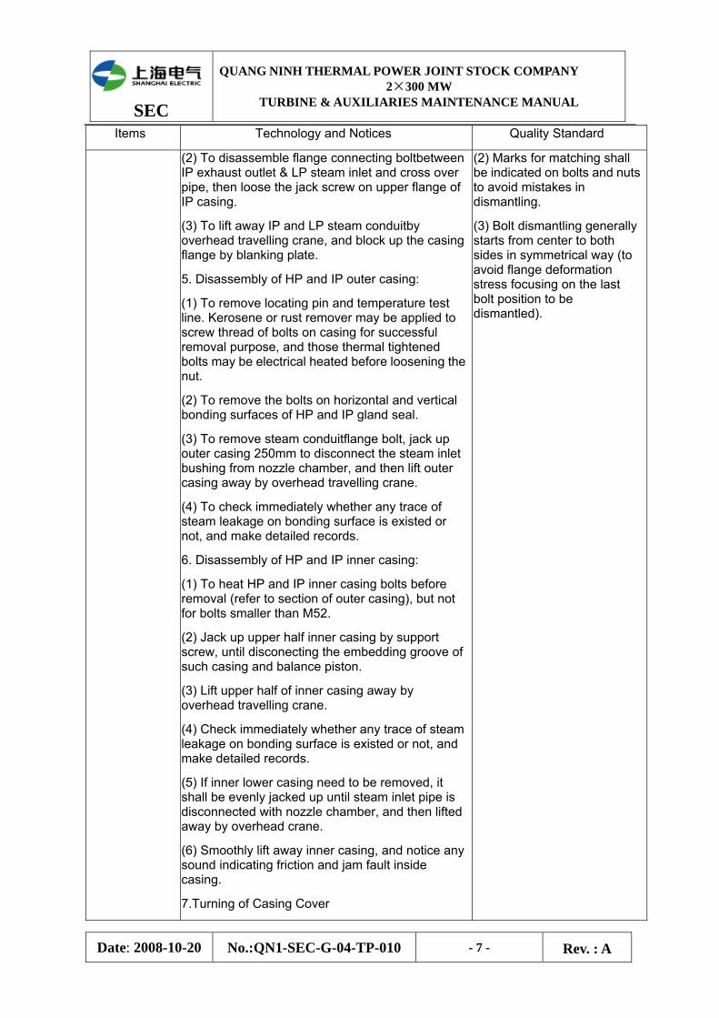
(2) To disassemble flange connecting boltbetween IP exhaust outlet & LP steam inlet and cross over pipe, then loose the jack screw on upper flange of IP casing.
(3) To lift away IP and LP steam conduitby overhead travelling crane, and block up the casing flange by blanking plate.
5. Disassembly of HP and IP outer casing:
(1) To remove locating pin and temperature test line. Kerosene or rust remover may be applied to screw thread of bolts on casing for successful removal purpose, and those thermal tightened bolts may be electrical heated before loosening the nut.
(2) To remove the bolts on horizontal and vertical bonding surfaces of HP and IP gland seal.
(3) To remove steam conduitflange bolt, jack up outer casing 250mm to disconnect the steam inlet bushing from nozzle chamber, and then lift outer casing away by overhead travelling crane.
(4) To check immediately whether any trace of steam leakage on bonding surface is existed or not, and make detailed records.
6. Disassembly of HP and IP inner casing:
(1) To heat HP and IP inner casing bolts before removal (refer to section of outer casing), but not for bolts smaller than M52.
(2) Jack up upper half inner casing by support screw, until disconecting the embedding groove of such casing and balance piston.
(3) Lift upper half of inner casing away by overhead travelling crane.
(4) Check immediately whether any trace of steam leakage on bonding surface is existed or not, and make detailed records.
(5) If inner lower casing need to be removed, it shall be evenly jacked up until steam inlet pipe is disconnected with nozzle chamber, and then lifted away by overhead crane.
(6) Smoothly lift away inner casing, and notice any sound indicating friction and jam fault inside casing.
7.Turning of Casing Cover
(2) Marks for matching shall be indicated on bolts and nuts to avoid mistakes in dismantling.
(3) Bolt dismantling generally starts from center to both sides in symmetrical way (to avoid flange deformation stress focusing on the last bolt position to be dismantled).
SEC
QUANG NINH THERMAL POWER JOINT STOCK COMPANY 2×300 MW
TURBINE & AUXILIARIES MAINTENANCE MANUAL
Date: 2008-10-20 No.:QN1-SEC-G-04-TP-010 - 8 - Rev. : A
Items Technology and Notices Quality Standard
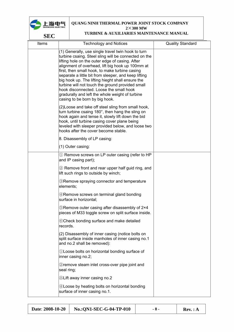
(1) Generally, use single travel twin hook to turn turbine csaing. Steel sling will be connected on the lifting hole on the outer edge of casing. After alignment of overhead, lift big hook up 100mm at first, then small hook, to make turbine casing separate a little bit from sleeper, and keep lifting big hook up. The lifting hieght shall ensure the turbine will not touch the ground provided small hook disconnected. Loose the small hook gradurally and left the whole weight of turbine casing to be born by big hook.
(2)Loose and take off steel sling from small hook, turn turbine csaing 180°, then hang the sling on hook again and tense it, slowly lift down the bid hook, until turbine casing cover plane being leveled with sleeper provided below, and loose two hooks after the cover become stable.
8. Disassembly of LP casing:
(1) Outer casing:
① Remove screws on LP outer casing (refer to HP and IP casing part);
② Remove front and rear upper half guid ring, and lift such rings to outside by winch;
③Remove spraying connector and temperature elements;
④Remove screws on terminal gland bonding surface in horizontal;
⑤Remove outer casing after disassembly of 2×4 pieces of M33 toggle screw on split surface inside.
⑥Check bonding surface and make detailed records.
(2) Disassembly of inner casing (notice bolts on split surface inside manholes of inner casing no.1 and no.2 shall be removed):
①Loose bolts on horizontal bonding surface of inner casing no.2;
②remove steam inlet cross-over pipe joint and seal ring;
⑧Lift away inner casing no.2
④Loose by heating bolts on horizontal bonding surface of inner casing no.1.
SEC
QUANG NINH THERMAL POWER JOINT STOCK COMPANY 2×300 MW
TURBINE & AUXILIARIES MAINTENANCE MANUAL
Date: 2008-10-20 No.:QN1-SEC-G-04-TP-010 - 9 - Rev. : A
Items Technology and Notices Quality Standard
⑤Lift away inner casing no.1;
⑥Check bonding surface of inner casing no.1 and no.2, and make detailed records;
⑦Smoothly lift away inner casing, and notice any sound indicating friction and jam fault inside casing.
II. Cleaning, checking and renovation
1. Steam Conduit:
(1) Clean and check flange plane of steam conduit, and grind if necessary to avoid leakage.
(2) Clean up rust and sundries inside steam conduit, and check crack, especially bending and weld seam, in general.
2. Turbine Casing
(1) Clean bonding surface, interface and flow path of turbine casing and components insides, remove burr, oxide scale, welding beading, rust and other sundries.
(2) Clean and check crack and leakage on inner and outer casing wall, as well as horizontal bonding surface;
(3) Check nozzle set and correct;
(4) Adjust and renovate working washer;
(5) Check LP casing manhole and safety valve;
3. Turbine Casing Bolt and Nut:
(1) Clean screw thread of bolt and nut by wire brush;
(2) Carry out turbine bolt hardness testing, NDT and metallographic examination, and creep elongation testing of bolt on control stage side
(3) Clean and check interface between spherical washer surfaces and interface between turbine casing and bolt nut for smoothness, burrless and good contact, and grind if necessary.
(4) Use black power to clean thread and interface of renovated bolts, nuts and washers or apply lubricant special for high temperature bolt before assembly.
(5) Clean and check locating pin and pin hole for smoothness and correctness, and use black power to clean pin and pin hole.
(6) Check flexibility of jack screw and clean burr on
(1) No crack or blow loss in turbine apperance inspection, bonding surface smooth and flat without steam leakage.
(2) No blow loss and crake on high pressure nozzle, no loosing, abrasion and deflection of gland sealing gears.
(3)Washer shall be flat and smooth without burr and bump.
(4) Bolts and nuts shall be cleaned, heating gate smooth, thread without defects such as crack and burr, and matching not over-tightening and loosing or jamming fault.
(5) Quality assessment of bolt shall refer to DL439-91 Technical Guide for High Temperature Fastener of Thermal Power Plant.
(6) Good contact of washer with nut and turbine, not for 0.05mm feeler gauge.
(7) Locating pin and pin hole smooth, wihtout burr and bite mark, and bolt and screw nut be flexible.
SEC
QUANG NINH THERMAL POWER JOINT STOCK COMPANY 2×300 MW
TURBINE & AUXILIARIES MAINTENANCE MANUAL
Date: 2008-10-20 No.:QN1-SEC-G-04-TP-010 - 10 - Rev. : A
Items Technology and Notices Quality Standard
thread which can be reformed by screw tap if necessary, apply special lubricant to thread.
2.1.2 Maintenance of Turbine Casing
I. Surveying and Adjusting
1.Measure transversal and longitudinal level of split surface of turbine casing: place adjustable gradienter in the position indicated in the first overhaul to measure level directly, twice measurement for each position (the second time the gradienter turning 180 degree), take the mean value of two measurements and make record.
2.Combine casings and check deformation: lift upper half casing on the lower half, measure the gp of horizontal split surface of inner casing holes by feeler gauge in free state and cold tightening 1/2 or 1/3 of casing bolt, meanwhile check the roundness of each groove and undercut of slit surface of inner circle, and make record.
3.Measure and adjust the clearances of inner and outer casing in support and locating position.
4.Meaure and adjust turbine casing groove center: implement after rotor centering.
1. No abnormal changes of turbine level by comparison with last records.
2. After free combination of HP and IP inner and outer casing, general plane clearance shall be less than 0.05mm, and no abnormal changes of turbine deformation by comparison with last records.
Horizontal deviation of center of turbine casing groove shall not be greater than 0.10mm, and longitudinal deviation shall not be greater than 0.05mm by comparing with installation values.
2.2 Static Carrier Ring and Balance Piston Carrier Ring
Items Technology and Notices Quality Standard
2.2.1 Cleaning and Maintenance of Carrier Ring
Dismantling of Carrier Ring:
1. Heat and dismantle screw and locating pin on horizontal split surface of various retaining ring.
2. Jack up upper half of retaining ring by support screw, and lift it up stably and slowly by overhead crane.
3. Dismantle pressure plate and screw on horizontal split surface of lower half carrier ring, measure relevant clearances and lift the lower half ring out.
1. Horizontal bonding surface of retaining rings and of diaphragms shall be air tightening without leakage, and 0,03mm feeler gauge can not be inserted in case of provision of bolting fastening.
2. Diaphragm being without crack, bending and deformation, and position matching groove being
SEC
QUANG NINH THERMAL POWER JOINT STOCK COMPANY 2×300 MW
TURBINE & AUXILIARIES MAINTENANCE MANUAL
Date: 2008-10-20 No.:QN1-SEC-G-04-TP-010 - 11 - Rev. : A
Items Technology and Notices Quality Standard
2.2.2 Measurement and Maintenance of Static Carrier Ring
1. Check integrity of static blades on diaphragm of static carrier ring and on HP last two stage diaphragm board, and any cracks and other damages, as well as bending and deformation of diaphragm.
2. Clean static blade by sand-blasting as that for blade.
3. After alignment of rotor coupling, measure and adjust centers of carrier rings and diaphragm groove by false -shaft.
(1) Dismantle all gland steam blocks, lift in false-shaft, measure horizontal clearance a between carrier rings and b between diaphragm grooves at both sides by inside micrometer, as well as bottom clearance c.
(2)Deviation of groove center in horizontal is (a-b)/2, and that in vertical is c-(a+b)/2.
(3) Adjustment shall be done in case turbine groove center exceeds the standard. Adjust vertical deviation by increasing washer under bearing surface at both sides of diaphragm; adjust horizontal deviation by repairing welding of one side of bottom pin and rimming the other side, to achieve horizontal movement purpose.
4. Lift carrier rings into turbine casing, fix one dial gauge on turbine with gauge head vertically contacting the end surface of carrier ring, dig’s axial expansion clearance one by one. If digging failed, jacking up by jack can be used.
5. Check contact of bearing surface of supporting key of carrier rings by red lead powder (reaming if necessary): measure clearance of supporting position of carrier ring, adjust if clearance not satisfied.
smooth without burr.
3 .Expansion clearance at top of diaphragm remains at 1.5±0.25mm.
4. Retaining ring bolts shall be without loosening, disorder, crack and creep extension.
5. Standard of bore center of retaining rings: a-b≤±0.lOmm; c-(a+b)/2≤±0.05mm
6. Axial clearance between carrier ring and turbine casing:
HP & IP: 0.20±0.05mm;LP: 0.4±0.10mm.
7. Clearance of Supports of Carrier rings:
(1) Plane clearance between supporting key and upper half carrier ring: a=0~0.05mm;
(2) Clearance between supporting key and upper washer: b=0.15~0.20mm
(3)Radial clearance between outer circle of carrier ring and turbine casing: c=3mm
(4) Inner side of upper and lower washer shall be retracted d=0.75~0.80mm compared with that of inner wall of turbine casing.
(5) Plane clearance between lower washer and lower half carrier ring: e=0.40~0.50mm;
8. Radial clearance of LP diaphragm plate:
Grade Axial Clearance
1, 2 0.15~0.25mm
SEC
QUANG NINH THERMAL POWER JOINT STOCK COMPANY 2×300 MW
TURBINE & AUXILIARIES MAINTENANCE MANUAL
Date: 2008-10-20 No.:QN1-SEC-G-04-TP-010 - 12 - Rev. : A
Items Technology and Notices Quality Standard
3,4 0.20~0.30mm
5 0.21~0.29mm
6 0.28~0.44mm
7 0.32~0.48mm
9. Expansion clearance of horizontal bonding surface of LP diaphragm:
Grade.1: 0.20~1.OOmm
Grade 2~7: 1.54±.25mm
2.2.3 Adjustment of Static Carrier Ring and Blade
Assembly of Carrier Ring:
(1) Clean by blowing with compressed air.
(2) Install gland steam ring and spring inside, fix stop pin, and the following procedures refer to Section 2.1 Boxing-up of Turbine
2.3 Maintenance of Gland Steam and Shaft Sealing System
Items Technology and Notices Quality Standard
SEC
QUANG NINH THERMAL POWER JOINT STOCK COMPANY 2×300 MW
TURBINE & AUXILIARIES MAINTENANCE MANUAL
Date: 2008-10-20 No.:QN1-SEC-G-04-TP-010 - 13 - Rev. : A
Items Technology and Notices Quality Standard
2.3.1 Dismantling of Gland Steam and shaft seal blocks
1.Dismantle and rectify HP and LP rotor end shaft seal.
(1)\Remove four shell keys or locating pins, as well as bolts on bonding surface.
(2) Lift upper half of shaft seal shell out, check any leakage mark on plane, and wearing on gland stem section of rotor, and observe the correctness of relative axial position of dynamic and static parts, and inspect iprimarily the diameter of lower casing shaft seal shell and loosening in axial direction,
(3) Lift out upper and lower shaft seal shell, inject kerosene or anti-rust angent in position of gland steam block, mark on the block before dismantling and number the blocks in accordnce with steam flowing direction, and restore these parts in accordance with these marks.
(4)After placing aluminum spacer on gland steam block, slightly tap the block until it can move , draw out gland block by hand, and the tapping concentration being on gland root but not tooth. If dismantling is difficult subject to serious rust corrosion, steel plate can be filed to a smaller spacer with similar sectional profile of gland steam block, and then bend the copper rod to be arc shape and go against spacer on end surface of the said gland block, and tap by hammer. Gland stam blocks and spring sheethes dismantled shall be fastened togetehr and hung with signs.
1.Horizontal bonding surface of terminal gland steam sleeve being air tightening without trace of steam leakage, gooc contact, and feeler gauge 0.03mm failed in condition of locking screw provided.
2.Tapping on end of gland steam block shall be forbidden in dismantling of such block.
3.HP, IP and LP carrier ring, diaphragm serrated gland being complete, wihtout ommission, rupture and damages; spring with normal elasticity and without deformation and rupture.
2.3.2 Dismantling, Re-assembling, cleaning/Maintenance of gland steam and shaft seal block
(1) Clena gland steam block and outer casing bore groove and other parts by sand paper, grinding wheel or steel brush.
(2)Check spring sheet for flexibity, deforation and rupture.
(3)Check stop pin for rupture and loosening.
(4) Combine two upper shells, check condition of horizonal bonding surface, and scraping if necessary.
(5) Trim all gland steam tooth point and make it sharp, maintain original gear shape in scraping, and gear end in 0,3mm thickness.
(6) Dismantling and maintenance of static blade carrier ring gland steam, diaphragm gland steam, and balance piston gland steam shall be same with those for terminal shaft sal.
1.Horizontal bonding surface of terminal gland steam sleeve being air tightening without trace of steam leakage, gooc contact, and feeler gauge 0.03mm failed in condition of locking screw provided.
2.Tapping on end of gland steam block shall be forbidden in dismantling of such block.
3.HP, IP and LP carrier ring, diaphragm serrated gland being complete, wihtout ommission, rupture and damages; spring with normal
SEC
QUANG NINH THERMAL POWER JOINT STOCK COMPANY 2×300 MW
TURBINE & AUXILIARIES MAINTENANCE MANUAL
Date: 2008-10-20 No.:QN1-SEC-G-04-TP-010 - 14 - Rev. : A
Items Technology and Notices Quality Standard
elasticity and without deformation and rupture.
1. Standard of radial clearance of HP & IP casing gland is as follows:
Static blade and rotor gland: (0.75±0.05)mm;
Dynamic Blade and carrier ring gland: (0.75±0.05)mm;
HP & IP end gland:
Inner three (3) channels: (0.50±0.05)mm,
Outer one (1) channel: (0.75±0.05)mm;
Balance piston gland: (0.75±0.05)mm.
2.Contact well between arc sections of gland block, and can not insert feeler gauge 0.05mm.
3. Radial clearance of LP carrier ring gland:
Grade
Control Valve End
Motor End
1 1.1mm 1.1mm
2.3.3 Measurement and adjustment of gland steam and shaft seal clearance
1. Measuring and adjusting radial clearance of gland steam and shaft seal:
(1) Measure radial clearance of gland steam sheet on both sides by feeler gauges, and make detailed record.
(2) In order to adjust gland steam clearance, generally, false shaft disc will be used to measure radial clearance of each gland steam block, and decide to adjust specific gland steam block or to adjust bore center of carrier ring, in accordance with condition inside each carrier ring,
(3) In case no false shaft provided, stick several adhesive plasters on tooth of each gland steam block, plaster being with difference thickness in accordance with specification of clearance and applied with red leader powder, lift in and turn the rotor, and do necessary adjusting as contact mark on the said plaster.
(4)In restoration, apply rubber adhesive plaster to form a step of certain thickness at rotor gland steam as required clearance, apply red lead powder on the plaster, turn rotor to inspect contact of such powder (upper first, and then lower), if not, apply additional layer before recheck, and measure the min. clearance one by one. In measuring clearance of upper half, it is better to remove the lower half gland block, so as to identify the bumping position.
(5) Generally, turning of protruding shoulder bearing surface at back of gland block will be used to limit the gland clearance. In turning, the thickness of bearing face shall be measured at first and the face be marked on with turning amount, to avoid any mistakes. 2
1.Omm l.3mm

SEC
QUANG NINH THERMAL POWER JOINT STOCK COMPANY 2×300 MW
TURBINE & AUXILIARIES MAINTENANCE MANUAL
Date: 2008-10-20 No.:QN1-SEC-G-04-TP-010 - 15 - Rev. : A
Items Technology and Notices Quality Standard
3 l.5mm 1.9mm
4 1.3mm 1.4mm
5 1.3mm 1.6mm
6 Clearance of labyrinth ring:6.1mm
7 Clearance of labyrinth ring:6.1mm
4. Radial clearance of LP diaphragm gland:
Grade
Control Valve End
Motor End
l 0 0
2 1.Omm 1.Omm
3 1.3mm 1.Omm
4 1.3mm 1.Omm
5 1.5mm 1.Omm
6 1.65mm 1.65mm
2. Measure and adjust axial clearance of gland steam and shaft seal block: in general overhaul, only measuring record of monitoring on axial position, if adjusting needed, add washer at axial control ring of shaft seal block or carrier ring. If it is specific group of gland steam block that need to be adjusted, turning on one site; and spot welding or m.Measure and adjust circumferential expansion clearance of gland steam and shaft seal block:
(1) After adjustment of radial clearance of gland and shaft seal and renovation of contact end surface of gland block, measure difference between end surface of upper half gland block and shell split surface, and measure that for lower half gland block also, the sum of these differences are the expansion clearance (no clearance among end surfaces of gland blocks).
(2)In case circumferential expansion clearance is over-low, surface of gland block shall be grinded; if the clearance is over-high, cut off one thin sheet from wasted block, attach the sheet by flat head screw to or weld on end surface of gland block for filling up the clearance.
7 2.50mm 2.50mm
SEC
QUANG NINH THERMAL POWER JOINT STOCK COMPANY 2×300 MW
TURBINE & AUXILIARIES MAINTENANCE MANUAL
Date: 2008-10-20 No.:QN1-SEC-G-04-TP-010 - 16 - Rev. : A
Items Technology and Notices Quality Standard
5. Standard of radial clearance of LP end gland:
Inner three (3) channles: 0.50±0.05mm;
outer one channel: 0.75±0.05mm.
6. Axial fit clearance between gland block and shell groove: 0.05~0.10mm.
7. Axial expension clearance of HP & IP gland blocks: 0.20~0.30mm; Axial expension clearance of HP & IP gland blocks: 0.8~1.2mm
2.3.4 Re-assembly of gland steam and shaft seal blocks
1. Wipe gland steam, groove containing block inside turbine casing, gland steam block and spring sheet.
2. Re-assemble gland steam block and spring sheet in accordance with marks made in dismantling.
3.For restoration of lower half gland steam block, blow it with compressed air. Carefully recheck gland steam block and placed into turbine casing after confirming correct installation, and lift rotor in.
4. After restoration of upper half gland steam block, fasten the stop pin of gland steam block, blow with compressed air, and carefully recheck to prevent any wrong of instillation, then close upper half gland steam and shaft seal shell, place locating pin (key) in, and fasten bolts.
5.After restoration of all gland steam and shaft seal blocks, turn rotor and listen to make sure no abnormal sound inside gland steam and shaft seal block.
After restoration, each gland block shall react flexibly when pressing by hand, no jam fault, and connector of gland block being smooth, no opening on bonding surface, and contact well.
2.4 Maintenance of Sliding Pin System
2.4.1 Cleaning, Measurement and Maintenance of Sliding Pin on Front Bearing Box Seat
Items Technology and Notices Quality Standard
SEC
QUANG NINH THERMAL POWER JOINT STOCK COMPANY 2×300 MW
TURBINE & AUXILIARIES MAINTENANCE MANUAL
Date: 2008-10-20 No.:QN1-SEC-G-04-TP-010 - 17 - Rev. : A
1. Generaly, ordinary checking is not carried out for longitudinal and transversal pin at the bottome of turbine asing and bearing box, except some cases that damage caused by deformation or abnormals are emerged. Clean and check the claw block, pad block, connecting bolt between turbine casing and foundation fram, as well as platen of front and intermediate bearing box in each overhaul, in which measure and adjust clearance accordingly.
1.Clearance in each position shall meet requirement shown in fig.2-43.
2.Various sliding surfaces shall be without trace of wearing and jam fault.
3.Clearance of sliding pins shall be evenly distributed in the whole length.
2.4.2 Maintenance, Measurement and Location of HP, IP and LP Casing
1.Clean and check claw platen (only for those units bringing claw platen in support structure): polish the bearing surface and sliding surface by sandpaper, and ensure accurate clearance. The cleareance of claw platens can be adjusted by adding washer on bearing surface under platen.
2. Check any cracks on weld seam of vertical pin, seat and various guid keys between inner and outer casing, if any, polish the position with crack and implement repair welding; if to lift out inner casing, remove oxided skin on side face of vertical pin, check clearance and
3.Check interconnection bolts between support frame of IP exhaust casing and front & rear exhaust LP casing and bed plate; dismantle all interconnection bolts for cleaning, brush black lead powder on the bolts and restore in original position, and make sure clearance being satisified.
4.Check clearance between pressing plates of bearing seat: clean the plate, apply black lead powder on it before restoring for clearance measuring, if clearance not satisifed, file the bearing surface or adding washer for adjusting purpose.
5. Check various vertical pin, longitudinal pin and transversal pin:
(1)Draw out vertical pin between support frame and IP & LP exhaust casing, clean pin and pin groove by sand paper before applying black lead powder, and restore the pin to measure the adjusted clearance (exclude in non-regular projects).
(2)If difficulty existed to clean the longitudinal
4. After cleaning sliding pin system, seal up by adhesive cloth to prevent dirt dropping in.
5. Reducing tightening force of bolt or adding more washers to adjust clearance between interconnection bolts is forbidden.
6. For repair welding of pin side face, plane off 2mm of pin at first, then implement bead welding (welding material shall not have hardness lower than that of original pin), forbid using spot welding, twiddle or extrusion to repair bid gap.
7. Pay attention to strengthen the inpsection of pin groove corners, no cracks caused by stress concentration.
8. Inspection of pin welding seam shall be strengthen, and reaming locating pin hole and fixing locating pin can be

SEC
QUANG NINH THERMAL POWER JOINT STOCK COMPANY 2×300 MW
TURBINE & AUXILIARIES MAINTENANCE MANUAL
Date: 2008-10-20 No.:QN1-SEC-G-04-TP-010 - 18 - Rev. : A
and transversal pin, use compressed air to blow away dirt and sundries, apply black lead powder to measure clearance, and thoroughly clean bearing seat and turbine casing when they are dismantled.
implemented in case weld strength is inadequate.
2.5 Maintenance of Turbine Rotor
2.5.1 Blade Checking, Cleaning and Frequency Testing
1)Clean dynamic blade: liquid sand wash required in normal case. Special place shall be prepared if sand blasting by compressed air will be applied, to prevent environmental pollution, and wrapping and sealing the area on rotor forbidden for sand blasting, and solid dirties can be removed manually by non-quenched knife edge if sand wash does not work.
2)After inspection of rotor cleaning, measure frequency of LP blades at various stages, and compare them with setting values (except loosing installed blades).
2.5.2 Maintenance of Impeller
(1)Pay attention to inspection of blade shroud, riveting jig head, transmission from profile line to blade root, inlet and outlet edge, hardening section and blade root, etc.
(2) Check and confirm any damages on blade surface, such as gap, wearing, crack and so on, shroud loosing, deformation or friction, seal blade and other blade loosing, drawing outwards, tilting and displacement.
(3) Examine any suspect blades by NDT test (e.g. penetrate, magnetic particle and ultrasonic testing, etc.)
(4) Round and grind sharp gap and groove trace of blade inlet and outlet edge.
(5) Check water corrosion of last stage blade and last-but-one stage blade, make detailed record for comparison purpose.
(6) Tap with small hammer to check any loosing of balance block and bolt lock.
1. Liquid sand is preferred to clean the blade if conditinos provided. In case applying blast-sand by compressed air, wind pressure and jetting distance be appropriately limited, jetting time be controlled, to prevent possible damage caused to blade. In case jetting gun being blocked, air supply must be cut-off before checking valve and conduit.
2. Prior to blade washing, the scalling on it shall be sampled for analysis, if any rupture is found in dismantling, the section shall be appropriately protected for testing
SEC
QUANG NINH THERMAL POWER JOINT STOCK COMPANY 2×300 MW
TURBINE & AUXILIARIES MAINTENANCE MANUAL
Date: 2008-10-20 No.:QN1-SEC-G-04-TP-010 - 19 - Rev. : A
and analysis.
3. The sand particle used for cleaning blade shall be sieved by 40-mesh screen. Cleaned blade shall be wihtout rust.
2.5.3 Checking, Measuring and Renovation of Shaft and Shaft Diameter Check shaft surface, journal, thrust disk collar
and coupling:
(1) Check any friction trace and damage on journal, thrust disk collar, coupling outer surface, gland packing step and oil retaining ring outer face.
(2) Measure outer circle shaking of rotor parts (shaft sleeve, various stage impeller gland distributors, coupling thrust disc, etc.) and spoon-shape deflection of coupling, thrust disc and impeller, make detailed records and compare the record with standard and record made in last overhaul, and find reason and implement necessary treatment if any value exceeding standard one are found.
(3) Grind bearing journal and polish thrust disk collar by fine milling oil stone.
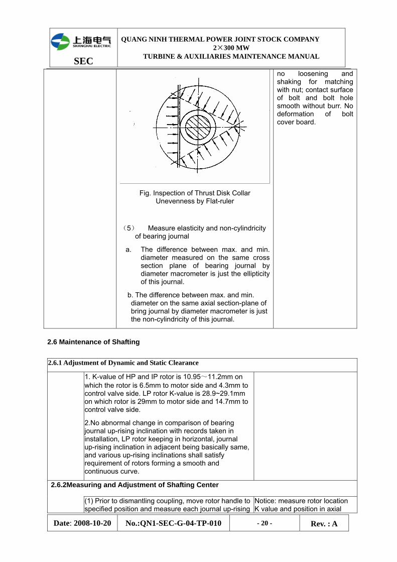
(4) Check plane unevenness of thrust disk collar, as shown in fig.2-23 below, put flat-ruler against end face of thrust disk collar, and measure gap between ruler and collar surface by feeler gauge.
1. Max. main shaft bending shall not greater than 0.04mm.
2. Thrust disc plane: spoon-shape deflection less than 0.02mm; unevenness less than 0.02mm. Others shall be referred to instructions of manufacturer.
3. Spoon-shape deflection of coupling plane shall be less than 0.03mm.
4. Working surface of shaft journal and thrust disc shall be smooth without pockmark or groove thread. Oil oil stone to grind the journal, move come-and-go along circumference but not in axial direction.
5. Ellipticity and un-roundness of shaft journal shall be less than 0.02mm.
6. No crack on coupling bolt, no interruption or disorder of thread, and
SEC
QUANG NINH THERMAL POWER JOINT STOCK COMPANY 2×300 MW
TURBINE & AUXILIARIES MAINTENANCE MANUAL
Date: 2008-10-20 No.:QN1-SEC-G-04-TP-010 - 20 - Rev. : A
Fig. Inspection of Thrust Disk Collar Unevenness by Flat-ruler
(5) Measure elasticity and non-cylindricity of bearing journal
a. The difference between max. and min. diameter measured on the same cross section plane of bearing journal by diameter macrometer is just the ellipticity of this journal.
b. The difference between max. and min. diameter on the same axial section-plane of bring journal by diameter macrometer is just the non-cylindricity of this journal.
no loosening and shaking for matching with nut; contact surface of bolt and bolt hole smooth without burr. No deformation of bolt cover board.
2.6 Maintenance of Shafting
2.6.1 Adjustment of Dynamic and Static Clearance
1. K-value of HP and IP rotor is 10.95~11.2mm on which the rotor is 6.5mm to motor side and 4.3mm to control valve side. LP rotor K-value is 28.9~29.1mm on which rotor is 29mm to motor side and 14.7mm to control valve side.
2.No abnormal change in comparison of bearing journal up-rising inclination with records taken in installation, LP rotor keeping in horizontal, journal up-rising inclination in adjacent being basically same, and various up-rising inclinations shall satisfy requirement of rotors forming a smooth and continuous curve.
2.6.2Measuring and Adjustment of Shafting Center (1) Prior to dismantling coupling, move rotor handle to
specified position and measure each journal up-rising Notice: measure rotor location K value and position in axial
SEC
QUANG NINH THERMAL POWER JOINT STOCK COMPANY 2×300 MW
TURBINE & AUXILIARIES MAINTENANCE MANUAL
Date: 2008-10-20 No.:QN1-SEC-G-04-TP-010 - 21 - Rev. : A
inclination. In measuring, place gradienter in the center of bearing journal, rectify transversal level of this gradienter, measure axial level and make detailed record. And then turn the gradienter 180°, measure again in the same position and make detailed record, and take a average of results in two measuring.
(2). After dismantling bolts on rotor couplings, jack two rotors along axial direction about 12mm, enable coupling washer completely disconnected with rotor concavo-convex surface, and then remove the washer. Measure again the journal up-rising declinations of rotor in free state, and make detailed record.
3.Measure again centers of various rotor coupling, and take this measured value as reference of adjustment in renovation phase.
4. Measure swing of various rotors (bending).
5.Measure spoon-shaped deflection of upper rotor components.
6. Measure ellipticity and taper.
7.Move rotor to specified position, accurately set K-value, measure gap of flow path of HP, IP and LP rotor, and then turn rotor 90° and measure again.
8.Mesure dynamic and static gap of dynamic and static blade gland in axial and radial direction.
9.Lift out rotor: remove thrust pad, use special tools for lifting rotor and posited the overhead crane in specified position, slightly lift up rotor to make it disconnect with bearing, level by use of square level, and slowly and smoothly lift out rotor.
prior to dismantling of HP & IP rotor and LP rotor, for reference in assembly.
2.6.3 Measuring and Adjustment of Rotor Center Items Technology and Notices Quality Standard
Aligning of Coupling:
(1) After dismantling of coupling, carry out center measuring before overhaul, make record as pre-record and compare it with record made in last overhaul.
(2) After grinding bearing pad pillow and sphere, align rotor in overhaul.
(3) Place rotor in by lifting , install device limiting rotor’s axial displacement, and adjust axial positions of two rotors to leave appropriate clearance between coupling plans of two rotors. Use special clip to measure
Standard of HP&IP rotor and LP rotor center:
(1)Circumference deviation: LP rotor height (0.20±0.02)mm, alignment of two sides ≤0.02mm.
Plane deviation: downward opening(0.152±0.02)mm; deviation of two sides ≤0.02mm
(2) Standard of LP rotor and generator rotor center:
Circumference deviation: LP rotor height (0.05± O.02)mm,

SEC
QUANG NINH THERMAL POWER JOINT STOCK COMPANY 2×300 MW
TURBINE & AUXILIARIES MAINTENANCE MANUAL
Date: 2008-10-20 No.:QN1-SEC-G-04-TP-010 - 22 - Rev. : A
clearance between coupling circumference and plane.
(4) Decide the adjusting value in accordance with measured value.
(5) Adjust spacer between pad pillow or iron mat, and grind up to requirement.
(6) Re-measure center, if not satisfied, keep adjusting until meeting the standard.
(7) After turbine boxing-up, verify various centers again and make records,
Notices in measurement of rotor bending, deflection and alignment:
(1) When turning rotor, securely press the plane of bearing pad by press plate, to prevent the pad from turning out.
(2) If turning rotor by overhead crane for measuring, loose hook a little bit after rotor turning to specified position, do measurement when the rotor is in free state.
(3) Direction (positive and negative) of reading value shall not be mistaken in measurement with dial gauge.
(4) In verifying rotor center line, frame and dial gauge used for alignment shall be securely fixed, and the transmission pin used for turning two rotors can not be too thin, generally smaller 1~2mm in diameter than that of hole.
(5) In recording center data, do not mistake the reading direction, and mark the card position and instruments. When measuring with feeler gauge, all procedures shall be carried out by one man only. In order to prevent error, continuously measure for two times, only after confirming the reading is stable, can the calculation adjustment be done.
(6) Use flat stainless steel sheet to adjust spacer under bearing pad, notice the number of steel sheet will not exceed 3~5 pieces in general and half piece of spacer is forbidden. After adjusting, recheck the contact condition of iron mat, and do grinding if necessary.
(7) In adjusting spacers on side face of bearing oil inlet hole, pay attention to hole opening which shall be smaller than oil inlet throttle orifice.
alignment of two sides ≤0.02mm;
Plane deviation: downward opening 0.152mm±0.02)mm; deviation of two sides ≤0.03mm
(3) Centers of generator rotor and exciter rotor:
Circumference deviation: high and low ≤0.05mm, left and right ≤0.05mm.
Plane deviation: downward opening 0.10~0.12mm; deviation of two sides <0.03mm
4. Rotor bending ≤0.04mm; shaking of coupling circumference ≤0.05mm
5. Thrust disc end cover deflection: ≤0.02; coupling end cover deflection ≤0.02mm.
6. Ellipticity and taper of various rotor journals shall not be greater than 0.02mm.
7. Rotor lifting require levelness with deviation not exceeding 2 division in gradienter.
SEC
QUANG NINH THERMAL POWER JOINT STOCK COMPANY 2×300 MW
TURBINE & AUXILIARIES MAINTENANCE MANUAL
Date: 2008-10-20 No.:QN1-SEC-G-04-TP-010 - 23 - Rev. : A
Restoration of coupling:
(8) Clean coupling plane and screw hole by cloth prior to assembly. Turn rotor to make two couplings being in opposite to marks previously done; apply a little turbine oil on bolt, drive the bolt into relevant screw hole by 2-pound hammer together with copper bar. After all bolts driven in, fasten pairs of bolts in diagonal one by one, and then fasten all again.
Measure shaking of coupling after connection, if measured value exceeding the standard, find out reason and eliminate it.
2.7 Maintenance of Bearing and Turning Gear
Front bearings of HP and IP casing shall be of self-setting tilting-pad bearing with two half parts, with locating pin on horizontal split surface, of which each half will be installed in the bearing body with spherical spacer for supporting and locating; Spherical spacer surface shall contact with washer in pad middle, so as to align the centers of bearing and rotor. Bearing body will be supported by five pieces of steel spacer on round hole of bearing seat, with washer between spacer and bearing body for adjusting bearing center, and axial locating device to prevent bearing’s axial movement. Rear bearing of HP and IP casing shall be of tilting-pad bearing, except no spherical spacer provided between bearing body and seat, others are same with those of front bearing.
Upper half pad of front bearing of LP casing shall be cylinder shape, and lower half will be formed by two pieces of titling pad. Spherical adjusting spacer will be provided between bearing body and seat. Rear bearing shall be cylinder shape, provided with spherical adjusting spacer.
Thrust bearing shall be posited before front bearing of HP and IP casing, and on one bearing seat. Thrust bearing shall be of self-setting type, and each pad will bear same load through pressure distributor. The pad and pressure distributor are all fixed in support ring which is fixed in the casing. Axial position of thrust bearing shell can be adjusted by positioning mechanism.
Front and rear bearing of generator shall be supported by end cover and be insulated, upper half being elliptic pad and lower half being cylinder pad.
Exciter shall have only one bearing, and the bearing shall be of tilting-pad bearing and supported by separated seat.
Items Technology and Notices Quality Standard
2.7.1 Maintenance
of Radial Bearing
1. Dismantling of Radial Bearing
(1) Dismantle temperature and vibration measuring elements, remove bolts and locating pins on horizontal split surface of bearing outer shell, jack up in the joint by supporting screw, and lift away bearing cover (front end cover of bearing no.1 removed first)
(2) Dismantle bolt and locating pin on split surface of spherical pillow, appropriately lift up rotor, switch split surface of bearing pad to horizontal position, and remove pins and
SEC
QUANG NINH THERMAL POWER JOINT STOCK COMPANY 2×300 MW
TURBINE & AUXILIARIES MAINTENANCE MANUAL
Date: 2008-10-20 No.:QN1-SEC-G-04-TP-010 - 24 - Rev. : A
Items Technology and Notices Quality Standard
connection bolts on horizontal surface of bearing pad shell (connector of jacking oil pipe first, if any).
(3) Lift away upper half pad, dismantle oil sealing ring, and lift away rotor before lower half pad.
2. Check bearing pad Babbitt metal interface, pad pillow interface, and check wearing, crack and integrity of Babbitt metal.
3. Measure gap and tightening force between bearing pads:
(1) When dismantle bearing, to number the pads, washers, spherical base block and bearing base block, as well as number their matching parts, to avoid mistakes.
(2) Measure side gap at four (4) corners of split surface of bearing pad by feeler gauge (insertion
depth about 1/10~1/12 of shaft diameter), and make detailed records
(3) Method of pressing lead wire to measure top oil gap: place two lead wire (fuse) with diameter 0.5mm greater than top gap width in transversal at both ends of journal (inner side of oil retaining ring), combine thicknesses of lead wires pressed out from upper and lower pad along arc length not less than 40° on journal cross section, viz. bearing pad top gap; if no suitable lead wire, place flat washers in same thickness at four corners of horizontal bonding surface, such thickness plus lead wire diameter being 0.5mm greater than top gap width, press lead wire its thickness, deduct washer thickness from remaining gap width, viz. bearing pad top gap width.
SEC
QUANG NINH THERMAL POWER JOINT STOCK COMPANY 2×300 MW
TURBINE & AUXILIARIES MAINTENANCE MANUAL
Date: 2008-10-20 No.:QN1-SEC-G-04-TP-010 - 25 - Rev. : A
Items Technology and Notices Quality Standard
(4) Measurement of top tightening force (or clearance) of bearing pad and pad pilling is same with method shown in (3). In case tightening force (or clearance) do not satisfy requirements, adjust thickness of spherical washer or spacer or add washer or spacer on split surface. Contact of washre on spherical surface can be checked by applying red lead powder, and those with poor contact shall be grinded and polished. The lower bearing pad bring three (3) washers, and washer 0.05~0.07mm will e placed at the bottom first in grinding. After sphere surface contact being accepted by testing, remove all washers added, lift rotor on it to check the satisfaction of its contact sate. Check tightness of split surface of bearing pad and pad pillow, and re-adjust tightening force if grinding is necessary.
(5) Measure directly the gap of oil seal in radial and axial direction with feeler on shaft and bearing.
4. Meauring gap of bridge gauge:
(1) Clean horizontal split surface of bearing seat, place bridge gauge in specified position on middle split surface of journal (
(2) Measure gap between journal and bridge gauge by feeler gauge, and make detailed record.
(3) For first measuring, indicate permanent mark where locate bridge gauge on horizontal split surface of bearing seat. Difference of two measured values is just tightening force of bearing pillow.
5. Maintenance and Adjustment Characteristic of Tilting Lobe Bearing
(1) Before remove the bearing, firstly loosen off the bolt and gasket of axial direction positioning as well as the plug of bearing body, and then mount the temporary bolt used for fastening the pad.
(2) The temporary bolt used for assembly of every pad end must be dismantled before rotor mounted, and then screw in the plug. It shall be attention that the plug must be below the bearing body surface after it has been screwed in..
(3) Check anti-braking spring of every upper half tile is integrated or not, its elasticity whether in condition. it shall be paid attention not to miss in
1. Babbitt metal of bearing pad shall be without wearing, crack and displacement, and axial contact with journal shall be greater than 80%.
2. No misalignment for combination of upper and lower pad, and 0.05mm feeler gauge can not be inserted into split surface of such combination.
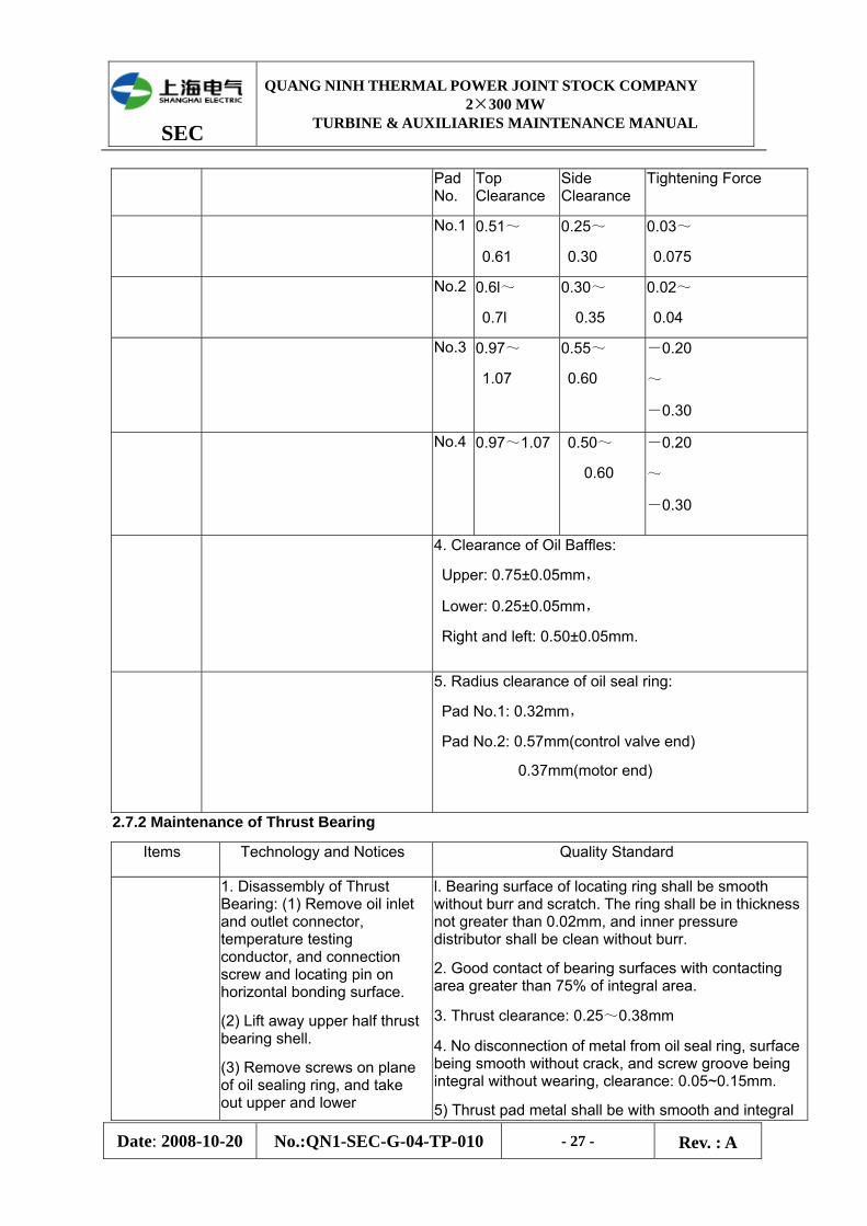
3. Clearance of bearing pads (unit: mm):

SEC
QUANG NINH THERMAL POWER JOINT STOCK COMPANY 2×300 MW
TURBINE & AUXILIARIES MAINTENANCE MANUAL
Date: 2008-10-20 No.:QN1-SEC-G-04-TP-010 - 26 - Rev. : A
Items Technology and Notices Quality Standard
assembly.
(4) When the clearance between bearing bush of tilting lobe and rotor needs adjustment, the adjustment shall be carried out as per the instruction requirement supplied by manufactory
(5) If the testing shaft is used for adjustment of tiling lobe clearance, then:
(1)Regard the sum of the diameter clearance of bearing bush and shaft neck actual size as the diameter to machining a bar of test shaft.
(2)Put the test shaft into bearing bush, and then adjust and shave the tiling lobe and testing shaft until meet the requirement of clearance being zero.
(3)Put in the rotor, and then readjust the bearing center to satisfy.
SEC
QUANG NINH THERMAL POWER JOINT STOCK COMPANY 2×300 MW
TURBINE & AUXILIARIES MAINTENANCE MANUAL
Date: 2008-10-20 No.:QN1-SEC-G-04-TP-010 - 27 - Rev. : A
Pad
No. Top Clearance
Side Clearance
Tightening Force
No.1 0.51~
0.61
0.25~
0.30
0.03~
0.075
No.2 0.6l~
0.7l
0.30~
0.35
0.02~
0.04
No.3 0.97~
1.07
0.55~
0.60
-0.20
~
-0.30
No.4 0.97~1.07 0.50~
0.60
-0.20
~
-0.30
4. Clearance of Oil Baffles:
Upper: 0.75±0.05mm,
Lower: 0.25±0.05mm,
Right and left: 0.50±0.05mm.
5. Radius clearance of oil seal ring:
Pad No.1: 0.32mm,
Pad No.2: 0.57mm(control valve end)
0.37mm(motor end)
2.7.2 Maintenance of Thrust Bearing
Items Technology and Notices Quality Standard
1. Disassembly of Thrust Bearing: (1) Remove oil inlet and outlet connector, temperature testing conductor, and connection screw and locating pin on horizontal bonding surface.
(2) Lift away upper half thrust bearing shell.
(3) Remove screws on plane of oil sealing ring, and take out upper and lower
l. Bearing surface of locating ring shall be smooth without burr and scratch. The ring shall be in thickness not greater than 0.02mm, and inner pressure distributor shall be clean without burr.
2. Good contact of bearing surfaces with contacting area greater than 75% of integral area.
3. Thrust clearance: 0.25~0.38mm
4. No disconnection of metal from oil seal ring, surface being smooth without crack, and screw groove being integral without wearing, clearance: 0.05~0.15mm.
5) Thrust pad metal shall be with smooth and integral
SEC
QUANG NINH THERMAL POWER JOINT STOCK COMPANY 2×300 MW
TURBINE & AUXILIARIES MAINTENANCE MANUAL
Date: 2008-10-20 No.:QN1-SEC-G-04-TP-010 - 28 - Rev. : A
semi-ring.
(4) Take out supporting ring, washer and pad.
2.Measuring gap between thrust pads: restore thrust bearing, one dial gauge measuring axial displacement of outer shell and another one on rotor disk measuring rotor displacement, and difference on dial gauge is total movement, so the gap is just the result of such movement subtracting bearing shell displacement.
3. Checking Thrust pad
(1) Check the pad’s Babbitt metal working face and measure the pad thickness, compare measured value with initial value, any abnormal shall be analyzed and treated.
(2) Check pin on pad back, and check pad swaying after assembly of thrust pad.
(3) Check and verify temperature measuring elements, under C&I assistance, and check measuring conductor.
(4) Check wedge-shape oil inlet gap between thrust pads: measure oil gap between outer openings by feeler gauge, and review shape of oil mark based on trace on bearing and Babbitt metal, and decide its conformance to drawing requirements.
surface without crack, flaking off, disconnection, wearing, electric corrosion and overload mark, overheating fusion or other mechanical damages.
Working mark on bearing pad shall be uniform and similar, with metal contact surface greater than 75% of whole area.
6. No obvious wearing found by comparing pad thickness with original record, and pad thickness difference shall be less than 0.02mm.
(5) Check contact state on flat plate after pad assembly.
4. Check Babbitt metal of oil sealing ring and the gap.
5. Check thrust bearing outer shell and accessories.
6. Assemble in inverted sequence, stick pad and

SEC
QUANG NINH THERMAL POWER JOINT STOCK COMPANY 2×300 MW
TURBINE & AUXILIARIES MAINTENANCE MANUAL
Date: 2008-10-20 No.:QN1-SEC-G-04-TP-010 - 29 - Rev. : A
balance block approaching to horizontal split surface with thick grease, to prevent falling off, ensure their free swaying and measure again the thrust gap after assembly.
7. Obey manufacturer’s instruction if axial position of thrust bearing shell need to be adjusted.
Bearing Cleaning and Restoration
1. Clean completely the sundries and grease stain in bearing oil chamber by kerosene and cloth.
2. Clean bearing cover and seat plane by knife.
3. Remove cloth remaining inside bearing seat and junk at dead corner by wet paste.
4. Disassemble bearing oil inlet and outlet pipe, blow compressed air, and restore the pipe or close up by clean cloth.
5. Blow compressed air, and put in various bearing components.
6. Put in rotor by lifting, restore upper half bearing pad and pillow, and connect jacking oil pipe.
7. After fastening coupling bolt, carefully check the inside of bearing chamber, and ensure no sundries left behind.
8. Install enclosure of upper half coupling, and fasten all screws.
9. Apply seal coating on split surface of bearing seat, except area along inner side of plane and peripheral area within 10mm from locating pin, close upper bearing cover, drive in locating pin, and fasten bolts.
SEC
QUANG NINH THERMAL POWER JOINT STOCK COMPANY 2×300 MW
TURBINE & AUXILIARIES MAINTENANCE MANUAL
Date: 2008-10-20 No.:QN1-SEC-G-04-TP-010 - 30 - Rev. : A
2.7.3 Maintenance of Generator Bearing
1.In bearing dismantling, exciter end removed first and then steam end:
(1)Dismantle the following parts: bearing labyrinth seal cover, oil baffle, vibration detector, insulation bearing pad support, semi-circle seat for bearing labyrinth seal cover (only at exciter end), temperature testing elements, jacking oil inlet pipe, and so on.
(2) Install rotor supporting tools on lower end cover support, and place copper board in 6mm thickness at contact of jack and rotary shaft, in order to protect the later.
(3) Fix bearing dismantling tools on side face of bearing pad, then remove fixing bolts and positioning pin of upper and lower pad, and lift out upper bearing pad.
(4) Mount M33 suspending ring in the screw hole on right side of split surface, remove blocking spacer at positioning pin, jack up rotor 0.25mm by jack, remove lower bearing pad and turn it up to be over shaft journal by overhead crane and steel rope, details see 2-12(e). Notice not to make steel rope rub the shaft journal.
(5) Mount bearing dismantling tools on side face of lower bearing pad, lift the lower pad out and dismantle support of insulation bearing pad.
l. Clearance of Bearings:
Top: 0.54~0.60mm;
Side face: 0.37~0.43mm;
Bearing fastening force: -0.13 ~ -0.38mm.
2. Clearance of Inner Oil Baffles:
Upper: 0.9mm;Lower: 0.5mm
Right and Left: 0.1mm.
3. Clearance of Labyrinth Seal:
Upper: 1.30~1.35mm;
Lower: 0.10~0.15mm;
Left and Right: 0.70~0.75mm
Clearance of lower center of plastic seal strip may be 0, and the min. of upper center may be 0.64mm.
4. Size of jacking oil bag shall be kept as 40×80×2mm.
5. Insulation performance of insulated gasket shall be tested by electric and satisfy requirement
6. Other quality requirements refer to Maintenance of Turbine Bearing.
SEC
QUANG NINH THERMAL POWER JOINT STOCK COMPANY 2×300 MW
TURBINE & AUXILIARIES MAINTENANCE MANUAL
Date: 2008-10-20 No.:QN1-SEC-G-04-TP-010 - 31 - Rev. : A
2.Clean, check and measure relevant clearances as procedures for maintenance of turbine bearing, and restore the fittings in inverted sequence of that for dismantling.
3. Prior to restore upper end cover, clean and check as requirements for restoration of turbine bearing.
Maintenance of Exciter Bearing and Mechanical Fittings
Refer to maintenance of turbine bearing.
l. Diameter clearance of exciter bearing pads:
0.25~0.30mm
2.Clearance of oil baffles of exciter bearing:
Upper: 0.30~0.35mm;
Lower: 0.20~0.25mm;
Right and Left: 0.05~0.10mm
3. Diameter clearance of oil baffles of exciter bearing: 0.40~0.45mm;
Fit tolerance of oil baffle in groove: ±0.01mm
4. Insulation performance of insulated gasket shall be tested by electric and satisfy requirement.
5. Other requirements refer to Maintenance of Turbine Bearing.
2.7.4 Maintenance of Turning Gear
Items Technology and Notice Quality Standard
I. Dismantling 1. After turning gear stopped, contact electric staff to dismantle motor and stroke switch wire.
2. Remoe oil inlet tube of turning gear.
3. Remove coupling botls of motor and gear box, and lift away motor.
4. Draw out locating pin, remove bolts on bonding surface of gear box and bearing suport, and lift away gear box in stable condition.
5. Turn gear box up to make bonding surface upward.
6. Dismantle connection pivot of swing link and balance wheel shell, to make them separated,
1. All bearings being intact, and fit clearance between bearing and shaft and between bearing and outer housing being within standard scope.
2. All components being intact, no crack and damages, oil inlet and outlet being smooth.
3. contacting spot of driving gear and gear on transmission device
SEC
QUANG NINH THERMAL POWER JOINT STOCK COMPANY 2×300 MW
TURBINE & AUXILIARIES MAINTENANCE MANUAL
Date: 2008-10-20 No.:QN1-SEC-G-04-TP-010 - 32 - Rev. : A
remove screw on bearing cover at both ends, and lift out balance wheel shell and large gear.
7. Pull out small pin on both sides of small balance wheel shaft, draw out small shfat, and take down balance wheel.
8. Remove screws on scillating cover at both sides, take down f balance wheel cover on one side, and draw out big gear and intermediate shaft from wheel shell, and check bearing pad on balance wheel cover on the other side.
9. Remove end cover of thrust bearing, take out thrust bearing and tie-rod, and separte various gears.
along gear width shall not be less than 65% and not be less than 40% for that along gear height,. Top clearance in gear meshing shall not be less than 1.25mm.
4. Contacting spot of driving gear and gear on oscillating gear along gear width shall not be less than 65% and not be less than 40% for that along gear height,. Top clearance in gear meshing shall not be less than 1.5mm.
5. Standard of turning gear shall be same with above-said.
6. Total clearance between two end faces of oscillating gear and balance wheel shell shall be 0.9~1.1mm.
II. Cleaning, Maintenance, Measurement
1. check contact state of meshing surfaces of various gears, and repair and grind gears with burr on edge.
2. Check contact of bearing pads and fit clearance, and scrape if necessary; replace gears with overlarge clearance or serious wearing.
3. Check any cracks and damages, etc. on components, check smoothness of oil inlet, and ensure no foreign matters in oil intake pipe.
4. Measure fit clearance between components.
7. Axle and trip shall be flexible.
8. Stop buffer spring shall be regular in shape without crack and rupture.
9. Turning gear quitting device and tail wheel for motor turning shall run smoothly without jam fault.

SEC
QUANG NINH THERMAL POWER JOINT STOCK COMPANY 2×300 MW
TURBINE & AUXILIARIES MAINTENANCE MANUAL
Date: 2008-10-20 No.:QN1-SEC-G-04-TP-010 - 33 - Rev. : A
III. Restoration
1. Clean components by gasoline, remove rust and apply appropriate turbine oil.
2. Assemble components in inverted sequence of dismantling.
3. After restoration of gear box, turn gear by hand to see if gear turning is flexible, and move operation handle to observe swing condition of balance wheel shell.
4. Check gear box and ensure no foreign matter inside, turn gear box and restore it on bearing pedestal.
5. After restoration of bearing pedestal, connect oil intake pipe.
6. Contact electric staff, connect motor and stroke switch wire..
7. Put lubrication oil pump into operation for power transmission purpose, and ensure electric steering in non-load test being correct.
8. Clear and count tools, clean the working site.
9. Place relevant technical documents on file.
2.8 Cylinder Box-up
2.8.1 Conditions required for boxing-up cylinder
Items Technology and Notices Quality Standard
1. Prepare cylinder box-up after maintenance of all components inside turbine casing are completed.
2.Technical materials below must be prepared before boxing-up:
(1) Record of turbine casing level;
(2) Record of clearance on horizontal bonding surface of turbine casing.
(3)Record of groove center inside turbine casing.
(4)Record of radial and axial clearance of flow paths.
(5) Record of support position and clearance of inner casing and retaining ring.
(6) Problems occurred in maintenance of all parts inside turbine casing and relevant testing report.
(7)Acceptance and signing report in each authorized
(1) The whole process of cylinder box-up shall be continuous without interruption, from lifting the first part of inner casing until the cover casing cover.
(2) Prior lifting each part into turbine casing, blow and clean the part with compressed air.
(3) In application of paint, reserve inner side of split surface and area 10mm around locating pin for exclusion of painting scope.
(4) Top clearance between bolts and cover nut shall be greater than 2mm, and that

SEC
QUANG NINH THERMAL POWER JOINT STOCK COMPANY 2×300 MW
TURBINE & AUXILIARIES MAINTENANCE MANUAL
Date: 2008-10-20 No.:QN1-SEC-G-04-TP-010 - 34 - Rev. : A
level. between inner casing nuts and inner wall of outer casing be greater than 4mm, and circumference clearance of bolts inside screw hole be greater than 0.5mm.
(5) Tightening of bolts on bonding surface between retaining ring and outer casing shall conform to Instruction of Bolt Tightening on Split surface of Introduced 300MW Unit Turbine.
(6) cold tightening value of bellow joint on LP cross over pipe shall be 6.5mm, and that of lower joint be 6mm.
(7) No deformation of cosmetic plate, and repairing or refinishing by painting after restoration in accordance with actual conditions.
2.8.2 Pre-work for boxing-up cylinder
Items Technology and Notices Quality Standard
(1) Maintenance of inside of inner and outer upper half casing shall have been completed, and turned to appropriate positions.
(2)Paints required by various bonding surfaces shall have been prepared.
(3)Tools, heating rod and power supply for tightening turbine casing bolts shall have been prepared and tested normal.
(4) Box-up working staff shall have worn special work cloth and shoe with soft sole, and take all stuff inside pocket out.
(5) Each matching surface in turbine casing shall have been wiped by black lead powder.
(1) The whole process of cylinder box-up shall be continuous without interruption, from lifting the first part of inner casing until the cover casing cover.
(2) Prior lifting each part into turbine casing, blow and clean the part with compressed air.
(3) In application of paint, reserve inner side of split surface and area 10mm around locating pin for exclusion of painting scope.
(4) Top clearance between bolts and cover nut shall be greater than 2mm, and that between inner casing nuts and inner wall of outer casing be greater than 4mm, and circumference clearance of bolts inside screw hole be greater than 0.5mm.
(5) Tightening of bolts on
SEC
QUANG NINH THERMAL POWER JOINT STOCK COMPANY 2×300 MW
TURBINE & AUXILIARIES MAINTENANCE MANUAL
Date: 2008-10-20 No.:QN1-SEC-G-04-TP-010 - 35 - Rev. : A
bonding surface between retaining ring and outer casing shall conform to Instruction of Bolt Tightening on Split surface of Introduced 300MW Unit Turbine.
(6) cold tightening value of bellow joint on LP cross over pipe shall be 6.5mm, and that of lower joint be 6mm.
(7) No deformation of cosmetic plate, and repairing or refinishing by painting after restoration in accordance with actual conditions.
2.8.3 Boxing-up Procedures and Notices
1) Clean inside of turbine casing, take all sealing fittings and non-relevant matters, and blow tiny sundries out with compressed air.
2) Clean inside of relevant bearing pedestal, and clean tiny sundries or particles by paste, and blow the oil intake and discharge pipe with compressed air.
3) Lift various lower half bearing pad one by one (incl. thrust pad) to place in position.
4) Lift lower half HP & IP inner casing, retaining ring of lower half static blade, balance piston gland ring and shaft seal housing one by one to place in position, prior to lifting, blow these components with compressed air, align level and apply special high temperature seal gel on outer edge, check and ensure no sundries among static blades stage by stage, and press gland steam blocks to check their flexibility and accurate mounting, and check contact with lugs.
5) Lift HP & IP rotor inside, when journal is going to enter bearing pad, pour clean turbine oil on journal.
6) Restore thrust clearance and recheck positions of rotor and turbine casing.
7) Re-measure clearance between flow parties.
8) Restore upper half static blade retaining ring and balance piston steam seal ring one by one, with same requirements shown in (4), and apply special high temperature seal gel on horizontal split surface.
9) Fasten bolts on horizontal split surface of static blade retaining ring and of balance piston ring as required.
10) Restore upper half HP & IP inner casing, with same requirements in (8), and fasten bolts on split surface as required.
11) Restore upper half HP & IP outer casing, and apply special high temperature seal gel on split surface, and fasten bolts on split surface as required.
12) Turn rotor and confirm no abnormal sound in casing by use of special device.
SEC
QUANG NINH THERMAL POWER JOINT STOCK COMPANY 2×300 MW
TURBINE & AUXILIARIES MAINTENANCE MANUAL
Date: 2008-10-20 No.:QN1-SEC-G-04-TP-010 - 36 - Rev. : A
13) Process of box-up of LP casing shall be similar with that of HP and IP casing.
5. Restoration of IP and LP Guide Steam Pipe:
1) Fasten flange bolts on LP casing at first.
2) Jack up flange on IP casing to position by jacking bolts, and then fasten this flange bolt.
6. Restore other piping.
7. Recover thermal insulation of IP and LP steam conduit.
8. Implement new thermal insulation of HP and IP upper half casing.
9. Restore cosmetic plate and repair by painting.
3 Maintenance Description of Steam Inlet Valves
This unit is provided with two (2) pieces of HP main stop valve fixed on both sides of HP casing, with outer shell cast together with control valve steam cabinet. This valve is of “double disc” combination type, provided with two (2) pieces of balance valve disc, and pre-lift valve is fixed inside main valve disc. Steam inlet pressure and spring fastening force will close such valve discs at the same time. Pre-lift valve is composed of two pieces for flexible connection between valve stem. When valve is closed and pre-lift valve can open intermediate valve inside main valve disk, this pre-lift vale will open to limit position at first, and further opening will open main valve disc; when main valve is fully opened, the back of main valve will go against door pole sleeve, so as to prevent steam leakage at valve stem.
3.1 Maintenance of HP Main Stop Valve
Items Technology and Notices Quality Standard
I. Dismantling and Measuring of Main Stop Valve
1. Remove the connection pin shaft of lever bait and lever & connection rod, then loosen off the lever and measure the clearance between every pin shaft and its lining of lever and connection rod.
2. Loose the fasten screw of spring gland in partition, then equably loose and screw out 3 long screws until the combined spring entirely loosen off.
3.Remove the long screw, gland and 4 springs, measure every spring free length (from large to small H1、H2、H3、H4) to check the spring condition.
4. Take out the spring seat and its sphere seat from spring seat casing, then loose the fasten screw of joint surface between spring seat and valve cover, lastly suspend down the spring seat casing.
5. Fit up the compression lever on the spring guide, then check it block or not, that the block can be removed by the means of repeated pressing the guide with lever after lubricated.
l. Clearance between level pivot and bush: 0.03—0,10mm, without abnormal wearing on surface.
2. Make record of free length of compressed spring and compare it with original record; spring being without crack; end surface and center with serious deformation in vertical being corrected or replaced.
3. Returning stroke of spring guide rod: S1=3.0+-0.5mm
4. Flange surface being flat without rust, washer being without deformation and rupture; no leakage after restoration.
5. Thread of bolts on valve
SEC
QUANG NINH THERMAL POWER JOINT STOCK COMPANY 2×300 MW
TURBINE & AUXILIARIES MAINTENANCE MANUAL
Date: 2008-10-20 No.:QN1-SEC-G-04-TP-010 - 37 - Rev. : A
Items Technology and Notices Quality Standard
Put the cent meter on the top of guide, press the guide by lever to bottom and then loosen so as to rebound the lever helped with small spring force, lastly measure the rebound travel of spring guide. The measure shall be carried out repeatedly to confirm inerrably.
6. Press the spring guide by lever to make its closed side self-sealing contact, at this point measure the axial clearance S2 between spring lever plane and its lining.
7. Slowly pull out the spring guide to seal slope of main valve rod so as to contact with inner lining seal surface of main steam valve, measure the axial clearance S3 between spring lever plane and its lining, then make the value minus S2.
8 .Draw out spring guide pole, make seal surface of inner bush of main stop valve contact with seal surface of bush of spring guide pole, measure axial clearance S4 between plane of spring guide pole and its bush. Subtract S3 from axial clearance S4 is just stroke of main stop valve.
9. Remove flange or connector of lower drain pipe of valve surface, check contact and washer.
10. Heat bolts on valve cover by electric heating rod until the sound emitted by tapping nut with hammer become dumb, loose the nut by spanner, remove nut and spherical washer.
11. Lift out valve cover (valve tie-rod and valve disc) in horizontal and take off washer, if the valve body doesn’t move subject to high tightening force, special wedge iron will be driven into bonding surface uniformly on both sides to make valve body move outwards. The dismantled valve body shall be placed on special support in horizontal for convenience of further dismantling.
12. Check valve cover bonding surface and valve shell inner wall, contact of main valve disc and valve seat, and prepare protective measures for sealing of main stop valve opening.
cover being without crack, roughening and deformation; bolt hardness satisfying design requirement.
6. Spherical washer complete without crack, with good contact of upper and lower bearing surface.
7.. Seal surface of valve cover being dry and complete, no cross-through or deep mark and burr; washer being complete without damage and serious deformation.
8. Valve shell being without crack, sand hole and serious inclusion; valve seat being secure without loosening. Valve disc contacting continuously with seat in full circle, with average width, and do grinding if necessary until reface roughness reaching Ra0.400um.
II. Disassembly of Main Valve Disk and Valve Stem
1. Pull out spring guide rod, tap out locating pin on fixed guide rod and main valve stem, remove pin and spring guide pin.
2.Draw valve disc and main valve stem out of valve cover, and check and clean valve stem.
3. Set up main butterfly valve and valve stem
1. Valve stem shall be without serious wearing and bending, and the bending shall be less than 0.05mm.
2. Pre-lift valve disc line shall contact continuously
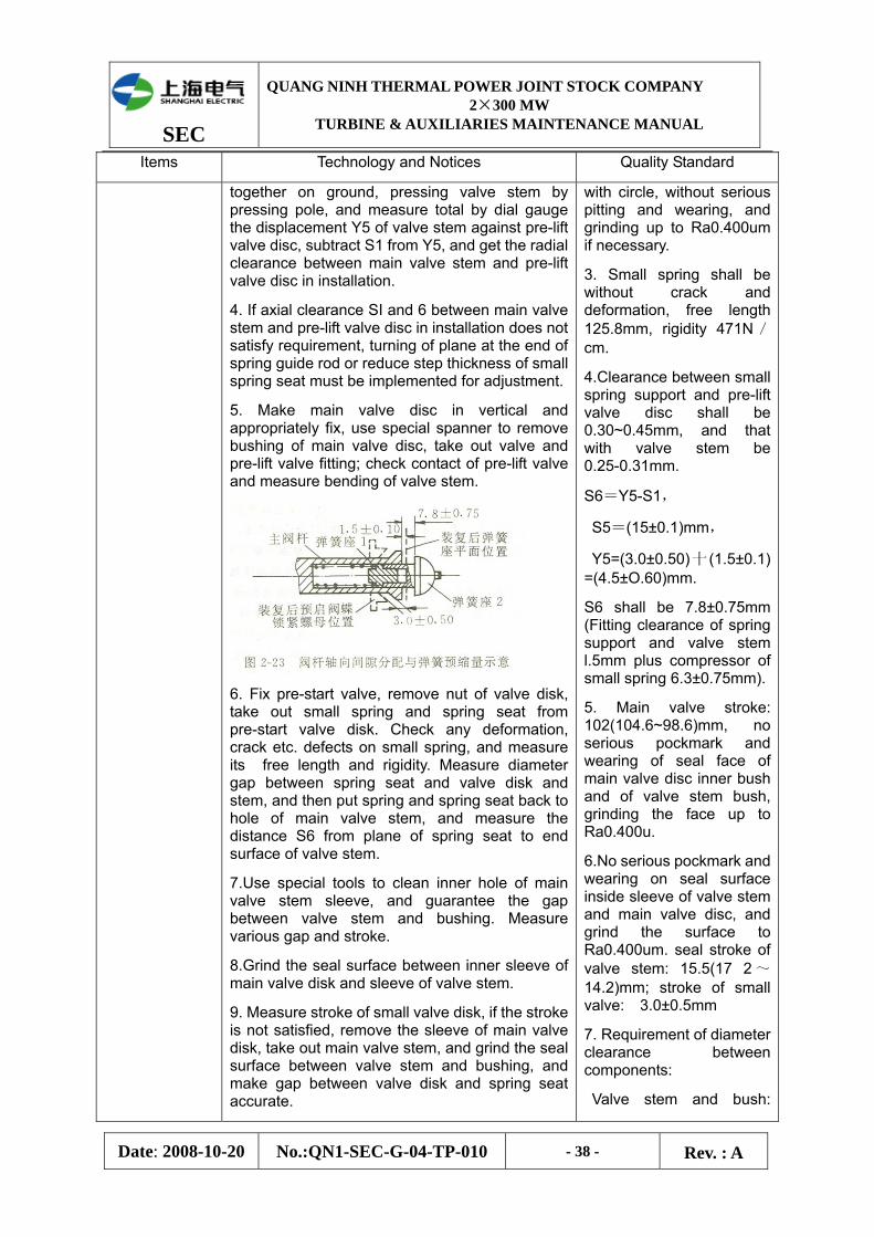
SEC
QUANG NINH THERMAL POWER JOINT STOCK COMPANY 2×300 MW
TURBINE & AUXILIARIES MAINTENANCE MANUAL
Date: 2008-10-20 No.:QN1-SEC-G-04-TP-010 - 38 - Rev. : A
Items Technology and Notices Quality Standard
together on ground, pressing valve stem by pressing pole, and measure total by dial gauge the displacement Y5 of valve stem against pre-lift valve disc, subtract S1 from Y5, and get the radial clearance between main valve stem and pre-lift valve disc in installation.
4. If axial clearance SI and 6 between main valve stem and pre-lift valve disc in installation does not satisfy requirement, turning of plane at the end of spring guide rod or reduce step thickness of small spring seat must be implemented for adjustment.
5. Make main valve disc in vertical and appropriately fix, use special spanner to remove bushing of main valve disc, take out valve and pre-lift valve fitting; check contact of pre-lift valve and measure bending of valve stem.
6. Fix pre-start valve, remove nut of valve disk, take out small spring and spring seat from pre-start valve disk. Check any deformation, crack etc. defects on small spring, and measure its free length and rigidity. Measure diameter gap between spring seat and valve disk and stem, and then put spring and spring seat back to hole of main valve stem, and measure the distance S6 from plane of spring seat to end surface of valve stem.
7.Use special tools to clean inner hole of main valve stem sleeve, and guarantee the gap between valve stem and bushing. Measure various gap and stroke.
8.Grind the seal surface between inner sleeve of main valve disk and sleeve of valve stem.
9. Measure stroke of small valve disk, if the stroke is not satisfied, remove the sleeve of main valve disk, take out main valve stem, and grind the seal surface between valve stem and bushing, and make gap between valve disk and spring seat accurate.
with circle, without serious pitting and wearing, and grinding up to Ra0.400um if necessary.
3. Small spring shall be without crack and deformation, free length 125.8mm, rigidity 471N/cm.
4.Clearance between small spring support and pre-lift valve disc shall be 0.30~0.45mm, and that with valve stem be 0.25-0.31mm.
S6=Y5-S1,
S5=(15±0.1)mm,
Y5=(3.0±0.50)十 (1.5±0.1) =(4.5±O.60)mm.
S6 shall be 7.8±0.75mm (Fitting clearance of spring support and valve stem l.5mm plus compressor of small spring 6.3±0.75mm).
5. Main valve stroke: 102(104.6~98.6)mm, no serious pockmark and wearing of seal face of main valve disc inner bush and of valve stem bush, grinding the face up to Ra0.400u.
6.No serious pockmark and wearing on seal surface inside sleeve of valve stem and main valve disc, and grind the surface to Ra0.400um. seal stroke of valve stem: 15.5(17 2 ~14.2)mm; stroke of small valve: 3.0±0.5mm
7. Requirement of diameter clearance between components:
Valve stem and bush:

SEC
QUANG NINH THERMAL POWER JOINT STOCK COMPANY 2×300 MW
TURBINE & AUXILIARIES MAINTENANCE MANUAL
Date: 2008-10-20 No.:QN1-SEC-G-04-TP-010 - 39 - Rev. : A
Items Technology and Notices Quality Standard
10. Clean and check any abnormal condition of big and small disk and other components.
11. Check any off-welding, crack etc. of steam strainer, if any, implement repair welding before heat treatment for stress elimination.
12. Check any off-welding and crack on weld of inlet steam damper, if any, implement repair welding of such damages (special measures prepared).
13. Check tightening of diffuser and outer shell, and ensure integrity of safety pin stem (one check for two overhauls)
0.26~0.33mm,
main valve disc and inner bush: 0.03~0.1lmm,
main valve disc and outer bush: 0.28~0.43mm,
valve stem and spring guide rod:O.13~0.18mm,
Spring guide rod and bush: 0.25~0.33mm,
Valve stem bush and valve cover: 0.03~0.13mm
Valve stem and valve disc nut: l.45~01.75mm,
Strainer frame and valve body edge at support: 0.22~ 0.48mm,
8. Plane clearance of inner ring of main valve disc: 0.25~ 0.33mm
II. Restoration
1.To restore the disassembled components in reversed sequence of disassembly, and check contact of valve line in restoration.
2. Sixteen (16) bolts M64×410mm for valve cover, cold fastening of the bolts with moment 680Nm at first, and hot fastening according to different materials.
1. In restoration, each movable bonding surface shall be surface without burr, wiped by black lead powder, and paint applied on flange bonding surface shall satisfy paint performance requirement for turbine casing.
2.Valve line shall be complete in full circle, without interruption and damage.
3. Bolts on valve cover (hot fastening corner valve/ elongation):
For 20Cr1MolVNbTiB, it is 94.5°/0.42mm;
For WR26, it is13.5° /0.5mm.
SEC
QUANG NINH THERMAL POWER JOINT STOCK COMPANY 2×300 MW
TURBINE & AUXILIARIES MAINTENANCE MANUAL
Date: 2008-10-20 No.:QN1-SEC-G-04-TP-010 - 40 - Rev. : A
3.2 Maintenance of HP Control Valve
Items Technology and Notices Quality Standard
I. Disassembly, Cleaning, and check.
1.Stop EH oil supply system, remove oil piping connected with operation seat of control valve. Note: in the future disassembling, check any marks indicating responding positions on matched components or not, if not, additional ones shall be made to avoid mistake in restoration.
2. Remove stop screw on connection axis pin at both ends of connection shaft, take out axis pin, and dismantle connection shaft.
3.Loosen hexagon socket screw on M27 cylinder head on bracket of servomotor.
4.Dismantle flange of steam drain piping of HP control valve stem bushing.
5. Replace stud on spring bracket with the long one, slowly loosen the cover on spring bracket to eliminate initial tightening force of spring.
6.Loosen bolts on HP control valve cover.
7.Lift out control valve and brackets for spring, servomotor and switch and place them on special inspection bracket, and prepare in time the protection of seal up of opening for control valve.
8.Dismantle cover on spring bracket, take out inner and outer spring, check spring cylinder, and measure spring’s free length and compare the measured value with initial one, and measure gap x between lower plane of spring seat and bracket.
9. Take spring seat out of support, pull out cylinder pin in center hole of sliding block by special tools.
10. Loose stop screw of branch lever pivot; dismantle pivot; dismantle connection pivot between lever and sliding block; loose control screw under pulling spring, and dismantle connection pivot between pulling spring and lever, and remove lever by lifting of overhead crane toward side of servo motor.
1. Lever pivots being flexible without jam fault; no wearing of bush and pin; fit clearance between pin and bush: two ends 0.01~0.05mm; middle 0. 05 ~ 0.20mm
2. Stop pressure plate screws on each pivot being integral and reliable.
3. Level and connection rod being straight without bending and deformation, bush mounting secure and reliable without loosening.
4. No scuffing of support fasteners and thread fittings being secure.
5. No rust, crack and over-deformation of cylinder spring. Free extension of spring in inner circle: 447mm; Free extension of spring in peripheral: 41 5mm.
6. No deformation and crack of spring cylinder, and no roughening of shoulder blades at both ends and of inner holes.
7. Flexible fitting between sliding block and pins with clearance: 0.01~0.05mm.
8. clearance between sliding block and guide sleeve: 0.33~0.38mm; fitting between guide sleeve and valve cover: interference 0~0.08mm.
9.Sliding block shall closely contact plane at valve stem end, and pin connecting well.
10. Contact surface of spring support with spring and with spring cylinder being smooth without wearing.
SEC
QUANG NINH THERMAL POWER JOINT STOCK COMPANY 2×300 MW
TURBINE & AUXILIARIES MAINTENANCE MANUAL
Date: 2008-10-20 No.:QN1-SEC-G-04-TP-010 - 41 - Rev. : A
Items Technology and Notices Quality Standard
11. Measure gap Y between lower plane of sliding block and valve stem sleeve.
12. Pull sliding block and check any jam fault of valve stem, and use dial gauge to measure stroke S of pre-start valve at top of sliding block, and seal stroke m of valve stem.
13. Use special punch to push out fixed pin for sliding block and valve stem, and remove the block from valve stem and measure gap between block and bushing.
14 Take out the valve rod from valve cover sheath. Measure gap between valve steam and disk sleeve and enclosure bushing, and then take out the valve disk and stem from valve cover bushing.
15. Loose jointing screw between valve disc and connection cap, then loose the cap, take out valve stem, check pre-lift valve line, and do grinding if necessary.
16. Check upper line on valve disk and seat with red lead powder, and grind if necessary.
17. Grind the bonding surface between control valve cover and steam chamber enclosure for continuous contact of such surface.
18.Clean and check axis pin and sleeve of level which shall be smooth, round and not damaged, draw spring and disk spring which shall be without rust corrosion and abnormal deformation, and measure gap between axis pin and shaft sleeve.
19. Clean dismantled components off rust and old dirty, and check any defects such as deformation and crack, and brighten by molybdenum disulfide or black powder.
20.Use compressed air to blow steam chamber.
1l. Valve stem surface being smooth, complete and round, without rust and wearing, bending being less than 0.05mm, and top thread of valve stem being complete without burr.
12. Inner sleeve hole shall be bright and clean, without serious deformation and wearing, steam drain hole inside sleeve being smooth.
13. Fit clearance between valve stem and seal sleeve: 0.25~0.30mm
14. Fit clearance of seal sleeve and valve cover: interference 0~0.06mm.
15. Pre-lift valve core and seat shall be bright and clean without spot and blowing mark, valve line connecting well.
16. Pre-lift valve stroke: (3 .26+-0.25)mm
17. Clearance between valve disc connection cap and gland sleeve: 0.25~0.31mm.
18. Seal stroke of control valve door rod: 46.10mm
19. Level stroke at servo motor end: 185.03mm
20. Contact mark of valve core and seat being uniform, contact surface being smooth, complete and round without spot, scar and damages.
21. Bonding surface between valve cover and shell being flat without spot and radial groove.
22.Valve housing shall be without crack, spelling, loosening or other serious defects, and no sundries left inside when assembling.
23. Bolts on valve cover shall
SEC
QUANG NINH THERMAL POWER JOINT STOCK COMPANY 2×300 MW
TURBINE & AUXILIARIES MAINTENANCE MANUAL
Date: 2008-10-20 No.:QN1-SEC-G-04-TP-010 - 42 - Rev. : A
Items Technology and Notices Quality Standard
be sampled for test as required by Department of Metal Supervision. If the test value exceeds standard value, implement treatment and replacement of the bolts. No crack and creep extension on bolts, no burr on thread, and brush black powder when in restoration.
24. Drain pipe flange being air tight, bonding surface smooth and flat, no radial scratch and groove, washer flat and intact.
II. Distortion 1.Distore the dismantled components in inverted sequence of dismantling.
2.Fasten sliding block at top of valve stem with 4511N·m, adjust any misalignment of fixed pin hole by adding one adjustment pad between valve stem and sliding block, and adjust the pad thickness for tightening of valve stem and sliding block, and align fixed pin hole.
3.Make detailed record of distance between binder plate of disk spring screw stem and bracket of servomotor, and restore in inverted sequence of dismantling.
4.Special pressure tools shall be used to replace SF-I bushing on level and connection shaft.
1. Cold tightening moment of bolts shall be 1000N·m, and initial extension 0.257mm.
2. After assembly, door rod inside valve shall go up and down smoothly without jam fault.
3.3 Maintenance of Reheat Steam Main Stop Valve
Items Technology and Notices Quality Standard
(I) Disassembly, cleaning and checking
1. Stop the EH oil system; remove the oil pipe joint to seal in time.
2 The fitting components shall be marked before disassembly to avoid mistake in assembly.
3. Suspend firmly the automatic interceptor valve, then loosen off bolt and oil drive interceptor valve.
4. Loose the bolt between the hydraulic actuator and spring bracket to separate them. Suspend well by overhead crane
1. The contact plane of every oil pipe joint is in condition and no leakage after assembly.
2. The motion of oil drive interceptor valve shall be flexible, the valve wire tight and no leakage.
3. Every fastener bolt and nut no burr, loose, tooth lack, deformation, the sphere gasket no deformation and crack, in
SEC
QUANG NINH THERMAL POWER JOINT STOCK COMPANY 2×300 MW
TURBINE & AUXILIARIES MAINTENANCE MANUAL
Date: 2008-10-20 No.:QN1-SEC-G-04-TP-010 - 43 - Rev. : A
Items Technology and Notices Quality Standard
before remove the control seat bracket.
5. Loosen off the hexagonal-head bolt between rocker arm frame and valve casing, then suspend away the rocker arm frame to put down the protective ring outside valve cover, remove the nut and gasket from valve cover.
6. Suspend firmly the valve disc, then slowly remove the shaft and put at a fixed place.
7 . After suspend out the valve disc, check the seal surface of valve disc and valve seat whether undamaged, and valve body inner wall whether crack and other damage.
8. Loose the bolt between the spring seat and frame, and then take off the spring seat.
9. Loose slowly the spring plank with long bolt, and take out the outer & inner spring to check whether crack, measure its free length and hardness.
10. Take off the connection rod in frame, clean and check the lever inner hole on connection rod, then measure the bore diameter.
11. Check the shaft , key way and key, and measure related size, clear up the ferric oxide dirty.
12. Clean and check the inner hole of every lining on shaft, and measure its size.
13. Clean and check the rocker arm inner hole and key way.
14. Loose the valve disc standby cap, then separate the valve disc with rocker arm, clean and check every components and measure relevant size.
15.The convex side and spheroid gasket contact spherical surface need be grinded before assembly, and check its contact condition.
every overhaul spot check them as per requirement of metal supervisory personnel.
4. The valve body and control seat shall be no damage such as crack.
5. The particularity sphere gasket on shaft must be grinded in installation, and required the100% surface contact on completed circle
6. Cover and spacer no damage and serious deformation.
7. The contact surface between valve disc and valve seat shall be 100% contact, and no deflation and wearing trace.
8. The pin on the spring outer shell shall be firmly fitting, and on the flange be loosening fitting.
9. Two of special long screw for disassembly & assembly spring with drawing No. W1066, after the spring assembly, the tool shall be keeping in condition.
10. The spring surface no crack and overage deformation, the free length and hardness keep a record and no obvious difference compared with original record. The spring shell no deformation and crack.
11. The every pin and shaft of connection rod flexible without block, contact well between key and its key way, the surface no serious wearing.
12. The connection rod straight without bending, every pin hole smooth, no wearing, corrosion and burr.
13.both sides clearance of
SEC
QUANG NINH THERMAL POWER JOINT STOCK COMPANY 2×300 MW
TURBINE & AUXILIARIES MAINTENANCE MANUAL
Date: 2008-10-20 No.:QN1-SEC-G-04-TP-010 - 44 - Rev. : A
Items Technology and Notices Quality Standard
connection rod and its joint respectively : 0.75±O.05mm
14. All the clearance between shaft and lining: 0.38 ~0.48mm
15. The clearance of complete cycle contact surface between standby cap of valve disc rod after screwed up and rocker arm: O.25~O.38mm
16. the diameter clearance between valve rod and rocker arm: 3.07 一 3.27mm; the fit up gap between rocker arm and lining: 2.29±1.50mm.
17. The contact spherical surface of rocker arm and valve disc and its nut need be grinded before assembly. The spherical surface contact shall be not less than 80%.
18. The clearance between control seat valve rod and lining: 0. 075~0.15mm
(II)Assembly
1. All the components shall be rubbed by supramoly or black lead powder, assembly them in inverted sequence of disassembly.
2. In assembly, the valve disc shall contact fully with limit block. If no proper contact, the check shall be carried out to ensure whether interference between casing and rocker. If there is a rotation interference, the leading portion of rocker arm shall be grinded. But, if still no proper contact, it shall be allowed to grind the interference part on casing until reach the requirement. Then check the fitting allowance whether meet the requirement, if necessary, the adjustment shall be carried out.
3 . To reach the requirement of hydraulic actuator, the limit block on cover shall be shortened or lengthened. In lengthen, the same material shall be used to weld it to limit block or overlay it for lengthening.
1. When disc reach the limit end, the hydraulic actuator journey keep a 177.8mm distance, here the disc shall be set back into casing not less than 25.4mm.
2 .The spacer between control seat rod and connection rod joint shall guarantee that the hydraulic actuator piston in oil cylinder can raise 6.4mm when valve in the closed position.
3 . The flange surface shall be coated with cylinder paint , and the bolt thread with anti-seizer paint before assembly.
4 . The cover nut shall be fastened by pneumatic wrench.
SEC
QUANG NINH THERMAL POWER JOINT STOCK COMPANY 2×300 MW
TURBINE & AUXILIARIES MAINTENANCE MANUAL
Date: 2008-10-20 No.:QN1-SEC-G-04-TP-010 - 45 - Rev. : A
3.4 Inspection of Reheat Control Valve
Items Technology and Notices Quality Standard
(I)Disassembly, cleaning , checking, measurement and repairing.
1. Stop the EH oil system, and remove it to connect the oil pipe with control seat of reheat governing valve
Attention: in the latter disassembly, the checking of fitting component shall be carried out to confirm whether have Para position remark, if not, the mark shall be firstly made for purpose of correct assembly.
2.Remove the flange bolt of drain pipe to loose flange,
3. Mount the special screw and nut used for disassembly of spring, with which fix the spring seat, then loose the cover bolt of reheat governing valve, last take off the nut and sphere gasket.
4. Suspend the control seat together with cover and disc by overhead crane to put them on the special inspection frame, and filled up by wood block under the disc.
5 . Take off the spacer of joint surface between cover and seat, and clean and check the spacer and the joint surface.
6. Suspend out the filter net to clean and check.
7 .Clean and check the seat whether loose, seal surface and inner hole of center lining whether undamaged, the fitting between seat and lining whether loose.
8. Between the cover and spring seat , the spring seat shall be jacked up by 3 jacks until to the location at which the stop pin between coupler and governing valve rod can be knocked out, then knock out the stop pin, loose off the governing valve rod from coupler, at last loose 3 jacks.
9. Loose off the socket head cap screw fastened between spring control seat and cover, and then remove the spring control seat.
10. Slowly loose the spring seat by special tool, take out the spring to clean,
1.The flange plane of drain pipe shall be flat, no corrosion and corrosion arisen from flue dust, the spacer be no deformation, no cracking, and no leakage after assembly.
2 . The bolt and nut of cover shall be no missing tooth, burr and deformation, and the test be carried out as per requirement of metal supervision department to dispose the non conformity; the sphere gasket be flat and smooth, no crack, and support plane contact be in condition.
3. The cover seal surface shall be flat, no throughout pull trace and burr; the spacer be integrated, no damage and serious deformation.
4. the filer mesh shall be unblock and no serious deformation; the clearance between inner circle and shell & cover be ≤0.05min, between outer circle of upper end stop and shell not more than 0.06mm.
5.The shell plane no cast crack, blowhole and severe inclusion; the seat no loose phenomenon.
6.The contact surface between disc and seat shall be continuous and well-proportioned in width.
7.The fitting between center lining of seat and seat : interference 0.025~0.075mm
8.The fitting between cover sleeve and cover : interference 0. 025~0.10mm
9.. The spring surface no rust crack, the free length no
SEC
QUANG NINH THERMAL POWER JOINT STOCK COMPANY 2×300 MW
TURBINE & AUXILIARIES MAINTENANCE MANUAL
Date: 2008-10-20 No.:QN1-SEC-G-04-TP-010 - 46 - Rev. : A
Items Technology and Notices Quality Standard
then check spring and its cartridge, lastly measure the spring free length and keep a record to compare with original record.
1 1. Disconnect the cover from valve rod by overhead crane, then clean the valve rod and lining, at last measure the clearance between upper & lower valve rod and lining.
obvious change compared with original value.
10. The valve rod no serious wearing, its curve value less than 0.05mm, which fitted with disc: interference 0~0. 05mm, with coupler: diameter clearance 0. 025~0.10mm. the clearance between valve rod and cover sleeve & seat center lining 0.33 ~ 0. 38mm.
11.The valve rod seal surface checked by red lead power shall be contacted in a complete circle after grinded, the total seal travel: 203mm.
1 2. The thread of coupler and valve rod shall be in condition, no burr, and seizure and loose; the spherical surface of sphere gasket be round and smooth, its contact surface be more than 75%.
13. The clearance between cover sleeve and disc: 0.7~0.9mm
14.Vertical clearance of piston ring: 3.225mm.
15. End seam clearance of piston ring: (0.25+-0.05)mm.
16.Grinding requirement for piston ring: ①the inner diameter circle contact of sheath drum in valve total travel shall be more than 30%; ② the circle direction contact of every ring shall be more than 80% of total width.
(II)Assembly 1. All the parts cleaned and checked shall be rubbed up by supramoly or shine black powder, the assembly be carried out as per the inverted sequence of disassembly.
2 .In installation of spring chamber, the piston rod of hydraulic actuator shall be pulled downwards (oil cylinder installed at the spring shell) until reach the cylinder
l . Before assembly of disc, the piston ring shall be coated anti- seizure paint.
2. The end face contact shall be more than 80% after screw up the coupler and valve rod with a 450N·n moment of force.
SEC
QUANG NINH THERMAL POWER JOINT STOCK COMPANY 2×300 MW
TURBINE & AUXILIARIES MAINTENANCE MANUAL
Date: 2008-10-20 No.:QN1-SEC-G-04-TP-010 - 47 - Rev. : A
Items Technology and Notices Quality Standard
bottom, then make a mark, lastly return a 6.35mm distance as the draft gear travel.
3 Screw up the coupler and valve rod at full tilt, and check contact condition of end face
4. Inspection of Inspection, Protection and Oil System
4.1 Inspection of Main Oil Pump
Items Technology and Notices Quality Standard
1. Remove the lubricant oil pipe on the main oil pump cover; loose the bolt of main oil pump joint surface, then pull out the alignment pin.
2. Suspend out the main oil pump upper cover, after rotor suspended, clean and check the pump casing, impeller and seal ring whether be integrated, no cavitations, no crack and deformation.
3. Check each component on shaft and the main oil pump whether be loose (when main oil pump is in condition and no cavitations in turbine flow section, commonly disassembly not to be needed)
4. The 4 two-half type seal ring including two inlet seal rings of main oil pump impeller ( one of left-hand turning and another of right-hand turning ) and two end shaft seal rings (same as former) shall be respectively rotated back and forth in the range of nearly 180 degree, then check its fitting condition.
5. Measure the radial & axial clearance (the Max. and Min, )of each seal ring.
6. Measure the wow flutter of turbine rotor, as well as that of each component in main oil pump.
7.Check the sealing condition of main oil pump shell by filler gauge and red lead powder after screw up the bolt.
1. Casing, impeller, seal ring, shaft and shaft liner shall be integrated, no crack, spelling and deformation, the fitting surface be smooth and no wearing, each component (including the connection between main oil pump speed regulator and rotor outer shaft) shall be fastened, through-flow section no cavitations.
2.Each seal ring can rotated freely, no loose, no block, the axial clearance : 0.05 ~
0.13mm , radial clearance: 0.05~0.1 5mm,pump shell two ends:0.05~0.1 5mm,
impeller inlet:0.05~0.15mm.
3.Wow flutter of main oil pump ≤0.03mm , non concentricity≤0.02mm, wow flutter of oil seal ring ≤0.02mm.
4.Midsplit surface clearance of main oil pump casing<0.03mm. red lead powder contact well and equably.
4.2 Inspection of Emergency Governor
1.Before disassembly, measure the clearance between fly hammer and hook,
1.The fly hammer shall be no burr and corrosion, no damage
SEC
QUANG NINH THERMAL POWER JOINT STOCK COMPANY 2×300 MW
TURBINE & AUXILIARIES MAINTENANCE MANUAL
Date: 2008-10-20 No.:QN1-SEC-G-04-TP-010 - 48 - Rev. : A
and keep a record.
2. Measure the relatively dimension a1 of fly hammer end by caliper depth rule and “v” type iron, then remove the stop-end set screw to screw out the stop-end and then make fly hammer up to its action location, lastly repeated measure the relatively dimension a2 of fly hammer end and the travel a=a2-a1 to record
3. Take out the fly hammer and spring, and clean and check each component and casing. Commonly if the action of emergency trip set is qualified, the spring aligning coil shall not be disassembly.
4. Measure the clearance of fly hammer with aligning coil, stop-end, casing and spring.
5.Measure spring free length and spring characteristic (spring characteristic test)
6 The assembly shall be carried out in inverted sequence of disassembly.
7. When the unit start up for the first time after emergency trip set disassembly, the over speed test must be carried out. If any action disqualification, adjustment shall go on. In adjustment of the spring aligning coil, firstly remove the lock ring and aligning pin, then screw down or take out the spring aligning coil if needed, lastly mount the aligning pin and lock ring.
for beating; the spring be no rust corrosion, wearing, crack and deformation; two end faces flat; fitting radius clearance with fly hammer:0.1一 0.4mm(tail section), fitting radius clearance with aligning coil : 0.4 一 0.8mm(end section).
2 .Fly hammer travel:(7 .1+-0 2)mm.
3. Radius clearance between fly hammer and aligning coil:0. l ~ 0.15mm ; radius clearance between fly hammer tail and casing:0.4—1.0mm;radius clearance between fly hammer inner hole and stop-end:0.1~0.15mm.
4.The spring aligning coil of fly hammer shall be changed about 40r/min every rotated crossing a stop-end.
5. After any adjustment of fly hammer spring, the over speed test shall be carried out again until qualified.
4.3 Maintenance of AC & DC Lubrication Oil Pump
Items Technology and Notices Quality Standard
I. Dismantling
1. Dismantle coupling bolts (appropriate keeping), measure coupling center; remove screw at bottom of motor, and deliver motor to department of electric for inspection.
2. Turn pump shaft and check any touching occurred.
3. After discharging oil in oil tank, remove screws fixing oil pump on oil tank, enter oil tank and remove outlet flange screw, lift out the oil pump, place it flatly in special oil disc for inspection with appropriate underplaying in the middle.
1. Coupling bolts shall be intact, rubber ring being without aging, deformation and damage.
2. Good matching of inner coupling hole and shaft with clearance 0~0.03mm. Key disconnects with key-way at top and contacts at both sides, no damage and cracks on surface.
3. Axial displacement: ≤0.12mm; shaking at impeller
SEC
QUANG NINH THERMAL POWER JOINT STOCK COMPANY 2×300 MW
TURBINE & AUXILIARIES MAINTENANCE MANUAL
Date: 2008-10-20 No.:QN1-SEC-G-04-TP-010 - 49 - Rev. : A
Items Technology and Notices Quality Standard
4. Remove screw on inlet strainer and dismantle strainer for cleaning and checking.
5. Remove screw on bonding surface of pump inlet section and pump body, dismantle inlet section and protection ring, use dial gauge to measure shaking of impeller inlet seal ring and axial displacement.
6. Remove connectors on oil pump for lubrication oil piping and bearing lubrication oil piping, and then dismantle lubrication oil piping.
7. Draw out coupling, remove key and appropriately store.
8. Remove screw on cover of ball bearing; take out bearing cover, and loose seal on bearing housing.
9. Remove locking washer on connection cap of impeller, loose the cap (turn to left), draw out impeller for cleaning and checking, and accurately place the adjusting spacer.
10. Dismantle connection screw of pump shell and bearing pedestal, and remove the pump shell and retaining ring.
11..Tap out bearing shaft and roller bearing together from impeller end by copper rod, and separate roller bearing and shaft.
12..Dismantle fixed bolts for upper, intermediate and lower bearing, separate upper component, sleeve and bracket of intermediate bearing, check bearings, measure gap between bearings and shaft.
3.Clean and check pump shell and body, and measure radial gap between impeller and seal ring.
14. Measure shaft bending and swinging.
seal ring: ≤0. 05mm; axial clearance between impeller and pump body and cover:7-9mm. when in restoring ball bearing, adjust it to middle position of axial clearance.
4. Impeller shall be without corrosion, crack and serious bumping damages on surface, securely fixed on shaft without loosening; thread of connection cap without wearing and scoring, key and key-way being integral without wearing and good matching, and locking gasket being secure.
5. Shaft surface shall be smooth without wearing, and the max. shaking after combination shall be less than 0.05mm.
6. Ball bearing shall be without bearing, fracture, serious pitting spot and flaking-off in running path, and tightening force fitting with bearing cover shall be 0.00~0.01mm, bearing turning easily after fixed inside.
7. Clearance between sliding bearings and shafts: 0. 06~0.15nm; secure matching with support, tightening force 0.02~0.04mm
8. After fastening locking nut, the shaking at seal ring of impeller shall not be greater than 0.05mm.
9 . Seal ring shall fit to pump body and cover with interference 0.02~0.04mm, secure locking, and axial clearance between ring and impeller 0.12~0.25mm.
10. Clearance between bearing seal parts and shaft shall be integrally uniform.
SEC
QUANG NINH THERMAL POWER JOINT STOCK COMPANY 2×300 MW
TURBINE & AUXILIARIES MAINTENANCE MANUAL
Date: 2008-10-20 No.:QN1-SEC-G-04-TP-010 - 50 - Rev. : A
Items Technology and Notices Quality Standard
11. After all parts restored, turning of coupling shall be easy without jam fault.
12. Axial clearance between two couplings shall be 5mm. Deviation of coupling centers shall be less than 0.05nlm.
II. Restoration 1.Clean, check and repair various components, and restore them in inverted sequence of dismantling.
2.Replace all seal washer and re-measure dimensions before repairing for standardization.
3.Re-measure the shaft swinging and rectify coupling center.
1. Prior to restoration, clean all inlet tube and fittings by kerosene, blow with compressed air, and wash fittings by clean turbine oil, to prevent rust corrosion.
2.After adjusting the motor turning, restore the coupling bolts.
4.4 Maintenance of Jack Oil Pump
Items Technology and Notices Quality Standard
I. Dismantling, Cleaning, Checking, Measuring
1. Discharge remaining oil, dismantle oil pipe and coupling, delivery motor to electric department for inspection and maintenance, mark on adjusting washers and store in appropriate condition.
2 . Use screw extractor to draw out the coupling on pump, remove anchor bolt and lift the pump to inspection area for dismantling.
3 Turn the manual disc of control screw, check return stroke 0-10mm .
4.Remove connection bolt between pump shell and variable mechanism, take off variable head, and mark on relative positions of piston and cylinder.
5.Take out sever (7) pieces of piston together with return disc, and dismantle concentrating ball, inner sleeve, spring and coat for cleaning and inspection, and measure free length and relevant clearance of spring.
(1) Radial clearance K between
1.Good contact of tube connector, washer complete and no leakage after washer installation.
2. Good matching of coupling inner hole and shaft, surface smooth without damage and crack.
3.Pisont surface being bright and clean, without damage, secure matching with sliding shoe, axial displacement being less than 0.01mm, fit clearance between piston and cylinder: K=0.01~0.02mm; no blockage of intermediate oil hole, piston can make return disc and variable head turn 20 degree in any direction under effect of itself gravity.
4. Position of sliding shoe on return disc shall be consistent in high and low, with deviation less than 0.01mm. no burr and grinding mark on contact surface between sliding shoe and variable head.
5. Concentrating ball being bright and clean on surface without rust, crack and deformation.
SEC
QUANG NINH THERMAL POWER JOINT STOCK COMPANY 2×300 MW
TURBINE & AUXILIARIES MAINTENANCE MANUAL
Date: 2008-10-20 No.:QN1-SEC-G-04-TP-010 - 51 - Rev. : A
Items Technology and Notices Quality Standard
piston and casing body.
(2) Radial clearance L between inner and outer bush.
6.In case any slight roughening of piston, use metallographical sand paper M0.5~M1.0 to polish it and place it into corresponding hole for moving condition.
7.If any displacement or wearing between piston and shoe head, replace the later, and then apply manual rivet pouching or rolling on lathe; after shoe head replaced, make piston move freely in any direction but not loosening. New piston shoe head shall be checked for consistence of axial height and low, and unqualified shall be corrected. And last apply red lead powder on variable head to check contact state.
8.Dismantle connection bolt between bearing pedestal and pump shell, take down oil distributor, and get out cylinder at the other end, and clean and check.
9. In case of any slight grinding mark on oil distributor, emery grinding grease M0.5~M1.0 can be used for grinding on special flat board.
10. Measure shaking of rotation shaft at both ends.
11. Dismantle lower flange, check oil resistance rubber seal ring and spring oil seal, take out rotating shaft together with ball bearing at coupling side, and measure radial clearance between bearing pedestal and ball bearing.
12. Use expansion clamp to dismantle spring retaining ring at ball bearing, and remove ball bearing and diaphragm ring at spline groove side for inspection and cleaning.
13. Dismantle variable mechanism, take out taper pin on control handle,
6. Contact surface of inner and outer sleeve shall be smooth without burr and wearing, radial clearance between inner and outer sleeve L=O.02~O.105mm
7.No spring tilting, deformation, rust and crack, good elasticity, no obvious change of free length and characteristics.
8.Non-parallelism of two planes of oil distributor tray shall be less than 0.005mm, surface bright and clean without rust, damage and burr, reliable fitting with shell, and no loosening and deformation of locating pin.
9. Tight matching of cylinder and cover, secure fitting with spline groove on transmission shaft, and contact surface with oil distributor being plat and tight, without burr, sundries, and dirt.
10. Radial clearance between bearing pedestal inner hole and ball bearing: J=0.06~0.095mm.
11. Journal jumping at coupling end ≤0.02mm, at spline end ≤0.01mm.
12. Ball bearing being complete without jam fault, loosening and pockmark, turning easy and flexible, and oil seal being without deformation and aging.
13. Transmission shaft being bright and clean, without bending, no burr and wearing on spline groove, tight matching of shaft with ball bearing and coupling, key and key-way being integral.
15. Plane of variable head and of return disc being smooth without burr and pulling trace, spherical surface being bright and clean, good connection of support and variable piston, rotating flexibly without loosening.
16.Control handle and locking nut finish roughening, and locking screw
SEC
QUANG NINH THERMAL POWER JOINT STOCK COMPANY 2×300 MW
TURBINE & AUXILIARIES MAINTENANCE MANUAL
Date: 2008-10-20 No.:QN1-SEC-G-04-TP-010 - 52 - Rev. : A
Items Technology and Notices Quality Standard
take off handle, remove locking nut, dismantle upper and lower flange, turn out control screw, take out baffle and piston. Measure clearance C between upper control screw and flange inner hole and D between lower one and the said inner hole, as well as clearance between screw and baffle. Dismantle scale and measure clearance A between indicating hand and scale support inner hole and B between hand shaft and the said hole.
14. Clean and check parts of variable mechanism, and measure upper and lower clearance and stroke of piston.
being secure.
17. Control screw being straight without bending, no thread damage, roughening or disruption; adjust screw and upper flange, radial clearance of baffle inner hole: 0.02~0.105min.
18. Scaling disc and transmission mechanism being flexible without jam fault of turning, indication correct, and radial clearance between indication needle and inner hole of scale seat 0.02~0.13mm; radial clearance between indicating finger shaft and scale seat inner hole: 0.015~0.08mm.
19. Variable piston surface being bright and clean, good matching with variable head, shell contact surface being smooth without burr and puling trace; radial clearance of upper and lower piston: 0.05~0.10mm; piston stroke: 21mm; fixing point and pin on scale being secure without wearing on surface.
II. Restoration
1. Wash all parts by clean turbine oil before fixing; do not bring any tiny sundries into pump.
2. Pay attention to locating pin hole and direction of oil disc in assembly to avoid any wrong.
3. Spring shall go inward in spring oil packaging.
4. Blow oil hole on each component for cleaning, and no omission of O-ring in each channel.
5. Restore the fittings in inverted sequence of dismantling, fully fill pump with turbine oil, turn pump shaft easily without jam fault, and recheck the displacement of pump shaft and travel of scale of variable displacement mechanism.
6. After place oil pump and motor in position, align the coupling center.
1. O-ring in each channel being integral without aging and deformation, groove smooth and flat, oil hole clean and smooth, oil pipe well connected, after restoration, turning smooth without jam fault, and no leakage on pump shell.
2. Requirement of coupling alignment: deviation of plane and circumference shall all be less than 0.05mm; clearance 1~3mm shall be reserved between coupling planes.

SEC
QUANG NINH THERMAL POWER JOINT STOCK COMPANY 2×300 MW
TURBINE & AUXILIARIES MAINTENANCE MANUAL
Date: 2008-10-20 No.:QN1-SEC-G-04-TP-010 - 53 - Rev. : A
4.5 Maintenance of Main Oil Tank and Oil Cooler
4.5.1 Maintenance of Main Oil Tank
Items Technology and Notices Quality Standard
I. Dismantling, Cleaning and
Checking
1. After inspection starts, oil working staff will completely discharge the oil in oil tank.
2. Clean cover of oil tank, dismantle equipments at top of oil tank one by one and seal the opening in time.
3. Working staff shall wear special work clothes and shoes, open manhole cover and take out strainer bucket. Enter oil tank from manhole, block the oil outlet at bottom of oil tank by cloth bag and clean. Forbid using the type of cloth made of yarn and felt.
4. Dismantle, clean and check oil level indicator (floater, sliding pole, finger and shell) and so on.
5. Clean and check various oil piping and attachments inside the oil tank, after all work completed, clean the oil tank again.
6. Clean oil tank inner wall and outer shell of piping by kerosene, and then use cloth without felt and paste to clean.
1. Strainer drum clean and no damages on new 150-mesh stainless steel strainer, locking bolt on strainer drum being secure and reliable.
2. No grease stain inside oil tank (incl. inside of interlayer and on piping attachments), rust, sundries and garbage, and no crack and oil leakage on oil piping.
3. Check the floater of oil lever indicator immersed in water or oil, no leakage, no bending and deformation of sliding pole, secure and reliable pin connecting pole, firm mounting of oil level finger, and accurate reading.
4. Exhaust fan blade being without damages, mounting secure, no bumping between stationary and dynamic fittings, no leakage on shell.
5.Tools and wiping cloth brought into oil tank shall be recorded, counted after working completed and not left behind inside oil tank.
II. Restoration 1. After all works inside the oil tank completed, take out the cloth bag at the oil outlet and check it together with chemical supervisor, place the strainer bucket (completely cleaned already and strainer cloth replaced if necessary) inside the manhole of oil tank, close the manhole cover.
2. Inspect motor of exhaust fan by electric department, dismantle exhaust fan, inspect impeller, shaft and outer shell, replace rubber seal ring; check exhaust fan oil drum by opening the cover, take out strainer of each channel for cleaning, and replace with new strainer cloth if any
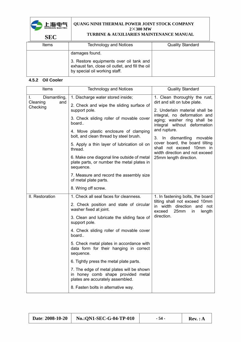
SEC
QUANG NINH THERMAL POWER JOINT STOCK COMPANY 2×300 MW
TURBINE & AUXILIARIES MAINTENANCE MANUAL
Date: 2008-10-20 No.:QN1-SEC-G-04-TP-010 - 54 - Rev. : A
Items Technology and Notices Quality Standard
damages found.
3. Restore equipments over oil tank and exhaust fan, close oil outlet, and fill the oil by special oil working staff.
4.5.2 Oil Cooler
Items Technology and Notices Quality Standard
I. Dismantling, Cleaning and Checking
1. Discharge water stored inside;
2. Check and wipe the sliding surface of support pole.
3. Check sliding roller of movable cover board..
4. Move plastic enclosure of clamping bolt, and clean thread by steel brush.
5. Apply a thin layer of lubrication oil on thread.
6. Make one diagonal line outside of metal plate parts, or number the metal plates in sequence.
7. Measure and record the assembly size of metal plate parts.
8. Wring off screw.
1. Clean thoroughly the rust, dirt and silt on tube plate.
2. Underlain material shall be integral, no deformation and aging; washer ring shall be integral without deformation and rupture.
3. In dismantling movable cover board, the board tilting shall not exceed 10mm in width direction and not exceed 25mm length direction.
II. Restoration 1. Check all seal faces for cleanness.
2. Check position and state of circular washer fixed at joint.
3. Clean and lubricate the sliding face of support pole.
4. Check sliding roller of movable cover board..
5. Check metal plates in accordance with data form for their hanging in correct sequence.
6. Tightly press the metal plate parts.
7. The edge of metal plates will be shown in honey comb shape provided metal plates are accurately assembled.
8. Fasten bolts in alternative way.
1. In fastening bolts, the board tilting shall not exceed 10mm in width direction and not exceed 25mm in length direction.

SEC
QUANG NINH THERMAL POWER JOINT STOCK COMPANY 2×300 MW
TURBINE & AUXILIARIES MAINTENANCE MANUAL
Date: 2008-10-20 No.:QN1-SEC-G-04-TP-010 - 55 - Rev. : A
4.6 Maintenance of Standby Sealing Oil Pump
Back-up pump for HP seal oil is of chevron gear oil pump, which shall be horizontally installed on top of main unit oil tank, with oil inlet pipe intending into lower part of oil tank, overflow valve and check valve being fixed on oil outlet piping. Pump outlet pressure setting value is of 0.9~1.0MPa, and pressure of outlet overflow valve is of 1.05~1.10MPa. Back-up HP seal oil pump shall be used at unit startup, and two flows of outlet pressure oil will be provided: one for back-up seal oil of generator seal pad, and the other for oil supplied for use of mechanical over speed and manual stopping and latch-on of oil pipe.
Items Technology and Notices Quality Standard
I. Dismantling
1.Dismantle safety enclosure and snap ring of coupling.
2. Remove electric motor wire and lift away motor.
3. Dismantle coupling by screw extractor.
4. Dismantle mechanical seal end cover, take out stationary ring, dynamic ring and spring.
5. Dismantle end cover at transmission side, mark on intermediate partition, to prevent exchanging during assembling.
6. Use special tools to dismantle intermediate partition and ball bearing of driving and driven gear.
7. Measure clearance between gears of oil pump.
8. After marking on corresponding meshing position of driving and driven gear, and take out the said gears.
9. Dismantle end cover on free side, and mark on intermediate partition.
10. Remove intermediate partition and ball bearing.
11. Dismantle pump overpressure valve, adjust screw on pump cover, measure and adjust screw length, and make detailed record.
12. Dismantle end cover of overpressure valve, and take out spring and valve core.
1. Clearance between end faces of driving and driven gear shall be 0.15~0.25mm.
2. Radial clearance between addendum top of driving and driven gear and circumference of pump shell shall be 0.05~0.12mm, and clearance between tooth surfaces shall be 0.20~0.40mm.
II. Cleaning and Checking
1. Clean all components by kerosene.
2. Check driving and driven gear, smooth surface, no damage of chevron gear, no corrosion and scar point on tooth surface, and secure installation on shaft.
3. Check tooth surface, good meshing, uniform eating print over 75% of whole tooth length.
4. Check gear end surface, smooth, no burr and no serious wearing.

SEC
QUANG NINH THERMAL POWER JOINT STOCK COMPANY 2×300 MW
TURBINE & AUXILIARIES MAINTENANCE MANUAL
Date: 2008-10-20 No.:QN1-SEC-G-04-TP-010 - 56 - Rev. : A
Items Technology and Notices Quality Standard
5. Smooth surface of driving and driven gear shaft without bending, secure fixing of gear locking nut, reliable insurance washer.
6.4 Check surface of ball bearing and inner and outer circle, no rust and scar point; retaining ring being integral, working easy and flexibly without noise; clearance meeting requirements.
7. Check inner end face of intermediate partition, no serious wearing, and smooth contact with gear end face without burr.
8. Check contact surface of mechanical seal dynamic and stationary ring, smooth without scratch; spring without rust and deformation and with normal elasticity; O-ring without aging and deformation, or else replace it.
9. Check contact line of pump overpressure valve core and seat, uniform and continuous; spring without rust and deformation and with normal elasticity.
10. check pump shell, no crack and air bore; check oil filling and air discharge valve.
III. Restoration 1. After washing, clean the components by blowing with compressed air, and apply turbine oil used in this unit on surface of gear and bearing, etc. before assembly.
2. Restore intermediate partition, bearing and end cover on free side in accordance with marks made in dismantling.
3. Install driving and driven gear, slightly tap them by copper bar.
4. measure clearance of gear end surfaces, of tooth surfaces and of addendum circle for satisfaction of standard.
5. Restore intermediate partition, bearing and end cover on transmission side.
6. Turning driving gear, running easy, no single face and jam fault; in case single face and jam fault, dismantle end surface on free side, use copper bar to slightly tap the shaft end of driving and driven gear, and restore the end cover after easy turning achieved.
7. Restore mechanical seal spring, dynamic and stationary ring, mechanical seal end cover and pump overpressure valve.
8. Restore coupling, turning easy, no single face
Deviation of coupling center shall not be greater than 0.05mm.
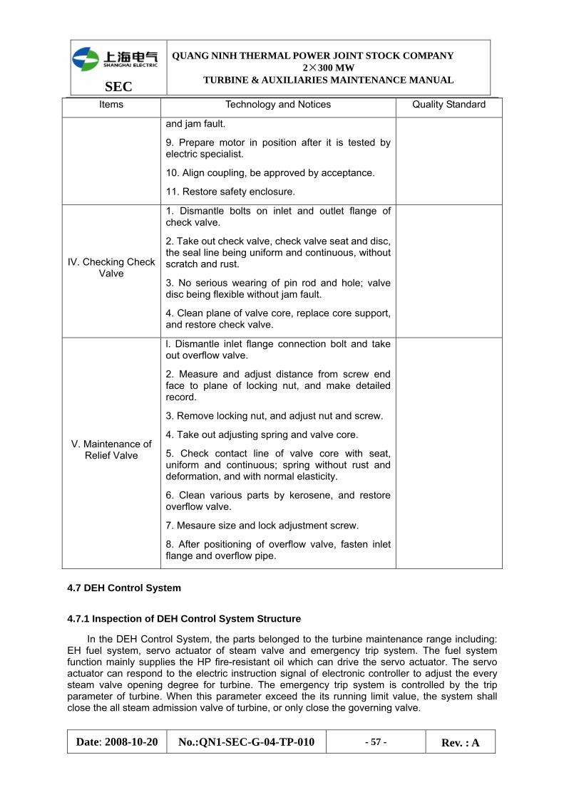
SEC
QUANG NINH THERMAL POWER JOINT STOCK COMPANY 2×300 MW
TURBINE & AUXILIARIES MAINTENANCE MANUAL
Date: 2008-10-20 No.:QN1-SEC-G-04-TP-010 - 57 - Rev. : A
Items Technology and Notices Quality Standard
and jam fault.
9. Prepare motor in position after it is tested by electric specialist.
10. Align coupling, be approved by acceptance.
11. Restore safety enclosure.
IV. Checking Check Valve
1. Dismantle bolts on inlet and outlet flange of check valve.
2. Take out check valve, check valve seat and disc, the seal line being uniform and continuous, without scratch and rust.
3. No serious wearing of pin rod and hole; valve disc being flexible without jam fault.
4. Clean plane of valve core, replace core support, and restore check valve.
V. Maintenance of Relief Valve
l. Dismantle inlet flange connection bolt and take out overflow valve.
2. Measure and adjust distance from screw end face to plane of locking nut, and make detailed record.
3. Remove locking nut, and adjust nut and screw.
4. Take out adjusting spring and valve core.
5. Check contact line of valve core with seat, uniform and continuous; spring without rust and deformation, and with normal elasticity.
6. Clean various parts by kerosene, and restore overflow valve.
7. Mesaure size and lock adjustment screw.
8. After positioning of overflow valve, fasten inlet flange and overflow pipe.
4.7 DEH Control System
4.7.1 Inspection of DEH Control System Structure
In the DEH Control System, the parts belonged to the turbine maintenance range including: EH fuel system, servo actuator of steam valve and emergency trip system. The fuel system function mainly supplies the HP fire-resistant oil which can drive the servo actuator. The servo actuator can respond to the electric instruction signal of electronic controller to adjust the every steam valve opening degree for turbine. The emergency trip system is controlled by the trip parameter of turbine. When this parameter exceed the its running limit value, the system shall close the all steam admission valve of turbine, or only close the governing valve.
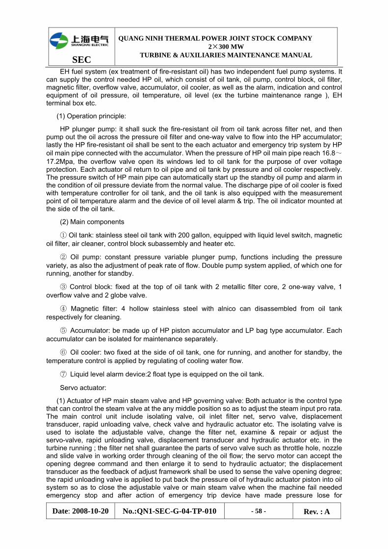
SEC
QUANG NINH THERMAL POWER JOINT STOCK COMPANY 2×300 MW
TURBINE & AUXILIARIES MAINTENANCE MANUAL
Date: 2008-10-20 No.:QN1-SEC-G-04-TP-010 - 58 - Rev. : A
EH fuel system (ex treatment of fire-resistant oil) has two independent fuel pump systems. It can supply the control needed HP oil, which consist of oil tank, oil pump, control block, oil filter, magnetic filter, overflow valve, accumulator, oil cooler, as well as the alarm, indication and control equipment of oil pressure, oil temperature, oil level (ex the turbine maintenance range ), EH terminal box etc.
(1) Operation principle:
HP plunger pump: it shall suck the fire-resistant oil from oil tank across filter net, and then pump out the oil across the pressure oil filter and one-way valve to flow into the HP accumulator; lastly the HP fire-resistant oil shall be sent to the each actuator and emergency trip system by HP oil main pipe connected with the accumulator. When the pressure of HP oil main pipe reach 16.8~17.2Mpa, the overflow valve open its windows led to oil tank for the purpose of over voltage protection. Each actuator oil return to oil pipe and oil tank by pressure and oil cooler respectively. The pressure switch of HP main pipe can automatically start up the standby oil pump and alarm in the condition of oil pressure deviate from the normal value. The discharge pipe of oil cooler is fixed with temperature controller for oil tank, and the oil tank is also equipped with the measurement point of oil temperature alarm and the device of oil level alarm & trip. The oil indicator mounted at the side of the oil tank.
(2) Main components
① Oil tank: stainless steel oil tank with 200 gallon, equipped with liquid level switch, magnetic oil filter, air cleaner, control block subassembly and heater etc.
② Oil pump: constant pressure variable plunger pump, functions including the pressure variety, as also the adjustment of peak rate of flow. Double pump system applied, of which one for running, another for standby.
③ Control block: fixed at the top of oil tank with 2 metallic filter core, 2 one-way valve, 1 overflow valve and 2 globe valve.
④ Magnetic filter: 4 hollow stainless steel with alnico can disassembled from oil tank respectively for cleaning.
⑤ Accumulator: be made up of HP piston accumulator and LP bag type accumulator. Each accumulator can be isolated for maintenance separately.
⑥ Oil cooler: two fixed at the side of oil tank, one for running, and another for standby, the temperature control is applied by regulating of cooling water flow.
⑦ Liquid level alarm device:2 float type is equipped on the oil tank.
Servo actuator:
(1) Actuator of HP main steam valve and HP governing valve: Both actuator is the control type that can control the steam valve at the any middle position so as to adjust the steam input pro rata. The main control unit include isolating valve, oil inlet filter net, servo valve, displacement transducer, rapid unloading valve, check valve and hydraulic actuator etc. The isolating valve is used to isolate the adjustable valve, change the filter net, examine & repair or adjust the servo-valve, rapid unloading valve, displacement transducer and hydraulic actuator etc. in the turbine running ; the filter net shall guarantee the parts of servo valve such as throttle hole, nozzle and slide valve in working order through cleaning of the oil flow; the servo motor can accept the opening degree command and then enlarge it to send to hydraulic actuator; the displacement transducer as the feedback of adjust framework shall be used to sense the valve opening degree; the rapid unloading valve is applied to put back the pressure oil of hydraulic actuator piston into oil system so as to close the adjustable valve or main steam valve when the machine fail needed emergency stop and after action of emergency trip device have made pressure lose for
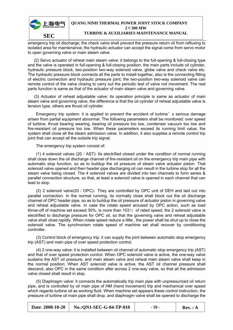
SEC
QUANG NINH THERMAL POWER JOINT STOCK COMPANY 2×300 MW
TURBINE & AUXILIARIES MAINTENANCE MANUAL
Date: 2008-10-20 No.:QN1-SEC-G-04-TP-010 - 59 - Rev. : A
emergency trip oil discharge; the check valve shall prevent the pressure return oil from refluxing to isolated area for maintenance; the hydraulic actuator can accept the signal come from servo motor to open governing valve or main steam valve.
(2) Servo actuator of reheat main steam valve: it belongs to the full-opening & full-closing type and the valve is operated in full-opening & full-closing position. the main parts include oil cylinder, hydraulic pressure block, two-position two-way solenoid valve, globe valve and check valve etc. The hydraulic pressure block connects all the parts to install together, also is the connecting fitting of electric connection and hydraulic pressure joint; the two-position two-way solenoid valve can remote control of the valve closing to carry out the periodic test of valve rod movement. The rest parts function is same as that of the actuator of main steam valve and governing valve.
(3) Actuator of reheat adjustable valve: its operation principle is same as actuator of main steam valve and governing valve, the difference is that the oil cylinder of reheat adjustable valve is tension type, others are thrust oil cylinder.
Emergency trip system: it is applied to prevent the accident of turbine’s serious damage arisen from partial equipment abnormal. The following parameters shall be monitored: over speed of turbine, thrust bearing wearing, bearing oil pressure too low, condenser vacuum too low and fire-resistant oil pressure too low. When these parameters exceed its running limit value, the system shall close all the steam admission valve. In addition, it also supplies a remote control trip joint that can accept all the outside trip signal.
The emergency trip system consist of:
(1) 4 solenoid valves (20/AST): Its electrified closed under the condition of normal running shall close down the oil discharge channel of fire-resistant oil on the emergency trip main pipe with automatic stop function, so as to buildup the oil pressure of steam valve actuator piston. That solenoid valve opened and then header pipe discharging oil can result in the turbine stop for all the steam valve being closed. The 4 solenoid valves are divided into two channels to form series & parallel connection structure, so that, at least a solenoid valve is opened in each channel that can lead to stop.
(2) 2 solenoid valve(20/OPC):They are controlled by OPC unit of DEH and laid out into parallel connection. In the normal running, its normally close shall block out the oil discharge channel of OPC header pipe, so as to buildup the oil pressure of actuator piston in governing valve and reheat adjustable valve. In case the rotate speed aroused by OPC action, such as load throw-off of machine set exceed 30%, is more than 103% of rated speed, the 2 solenoid valve is electrified to discharge pressure for OPC oil, so that the governing valve and reheat adjustable valve shall close rapidly. When rotate speed reduce a little , the power shall be shut up to close the solenoid valve. The synchronism rotate speed of machine set shall recover by conditioning controller.
(3) Control block of emergency trip: it can supply the joint between automatic stop emergency trip (AST) and main pipe of over speed protection control.
(4) 2 one-way valve: it is installed between oil channel of automatic stop emergency trip (AST) and that of over speed protection control. When OPC solenoid valve is active, the one-way valve sustains the AST oil pressure, and main steam valve and reheat main steam valve shall keep in the normal position; When AST solenoid valve is active, the AST oil channel pressure shall descend, also OPC in the same condition after across 2 one-way valve, so that all the admission valve closed shall result in stop.
(5) Diaphragm valve: it connects the automatically trip main pipe with unpressurized oil return pipe, and is controlled by oil main pipe of HM (hand movement) trip and mechanical over speed which regards turbine oil as working fluid. When machine set appears these control instruction, the pressure of turbine oil main pipe shall drop, and diaphragm valve shall be opened to discharge the
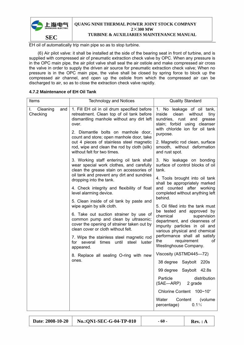
SEC
QUANG NINH THERMAL POWER JOINT STOCK COMPANY 2×300 MW
TURBINE & AUXILIARIES MAINTENANCE MANUAL
Date: 2008-10-20 No.:QN1-SEC-G-04-TP-010 - 60 - Rev. : A
EH oil of automatically trip main pipe so as to stop turbine.
(6) Air pilot valve: it shall be installed at the side of the bearing seat in front of turbine, and is supplied with compressed air of pneumatic extraction check valve by OPC. When any pressure is in the OPC main pipe, the air pilot valve shall seal the air ostiole and make compressed air cross the valve in order to supply the driven air source for pneumatic extraction check valve; When no pressure is in the OPC main pipe, the valve shall be closed by spring force to block up the compressed air channel, and open up the ostiole from which the compressed air can be discharged to air, so as to close the extraction check valve rapidly.
4.7.2 Maintenance of EH Oil Tank
Items Technology and Notices Quality Standard
I. Cleaning and Checking
1. Fill EH oil in oil drum specified before retreatment. Clean top of oil tank before dismantling manhole without any dirt left over.
2. Dismantle bolts on manhole door, count and store; open manhole door, take out 4 pieces of stainless steel magnetic rod, wipe and clean the rod by cloth (silk) without felt for two times.
3. Working staff entering oil tank shall wear special work clothes, and carefully clean the grease stain on accessories of oil tank and prevent any dirt and sundries dropping into the tank.
4. Check integrity and flexibility of float level alarming device.
5. Clean inside of oil tank by paste and wipe again by silk cloth.
6. Take out suction strainer by use of common pump and clean by ultrasonic; cover the opening of strainer taken out by clean cover or cloth without felt.
7. Wipe the stainless steel magnetic rod for several times until steel luster appeared.
8. Replace all sealing O-ring with new ones.
1. No leakage of oil tank, inside clean without tiny sundries, rust and grease stain; forbid using cleanser with chloride ion for oil tank purpose.
2. Magnetic rod clean, surface smooth, without deformation and rust spot.
3. No leakage on bonding surface of control blocks of oil tank.
4. Tools brought into oil tank shall be appropriately marked and counted after working completed without anything left behind.
5. Oil filled into the tank must be tested and approved by chemical supervision department, and cleanness of impurity particles in oil and various physical and chemical performance shall all satisfy the requirement of Westinghouse Company.
Viscosity (ASTMD445—72)
38 degree Saybolt 220s
99 degree Saybolt 42.8s
Particle distribution (SAE—ARP) 2 grade
Chlorine Content 100~10“
Water Content (volume percentage) 0.1%
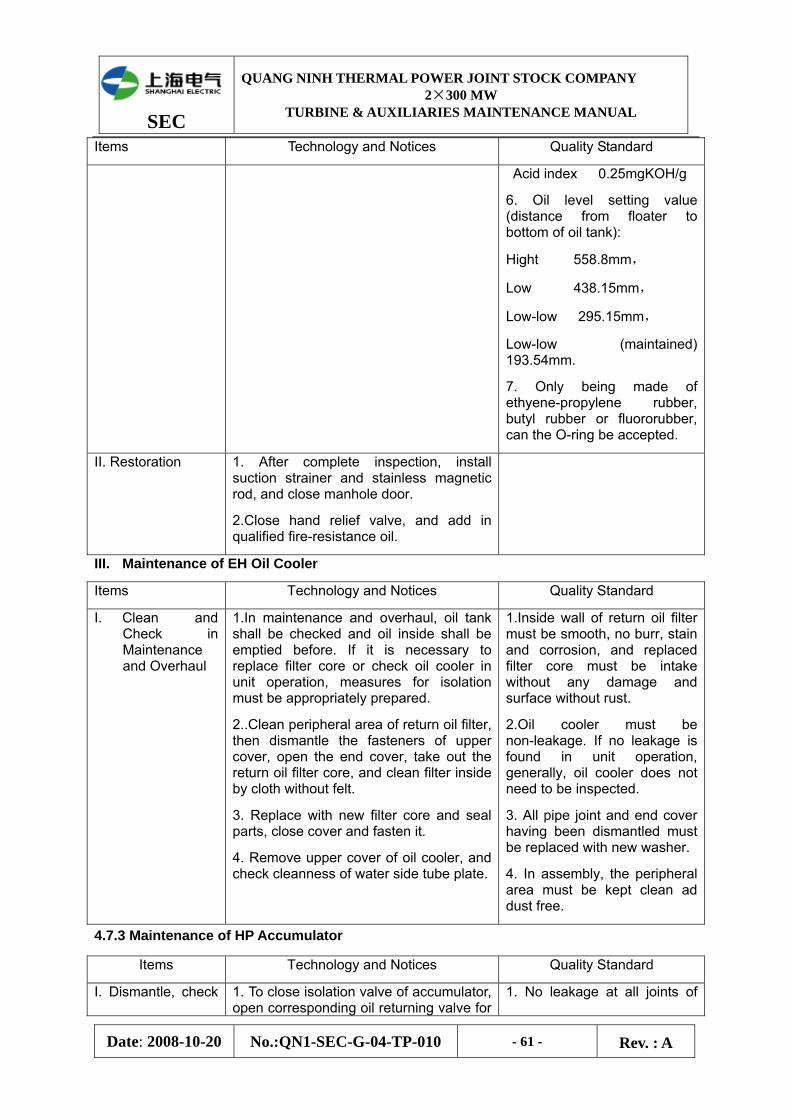
SEC
QUANG NINH THERMAL POWER JOINT STOCK COMPANY 2×300 MW
TURBINE & AUXILIARIES MAINTENANCE MANUAL
Date: 2008-10-20 No.:QN1-SEC-G-04-TP-010 - 61 - Rev. : A
Items Technology and Notices Quality Standard
Acid index 0.25mgKOH/g
6. Oil level setting value (distance from floater to bottom of oil tank):
Hight 558.8mm,
Low 438.15mm,
Low-low 295.15mm,
Low-low (maintained) 193.54mm.
7. Only being made of ethyene-propylene rubber, butyl rubber or fluororubber, can the O-ring be accepted.
II. Restoration 1. After complete inspection, install suction strainer and stainless magnetic rod, and close manhole door.
2.Close hand relief valve, and add in qualified fire-resistance oil.
III. Maintenance of EH Oil Cooler
Items Technology and Notices Quality Standard
I. Clean and Check in Maintenance and Overhaul
1.In maintenance and overhaul, oil tank shall be checked and oil inside shall be emptied before. If it is necessary to replace filter core or check oil cooler in unit operation, measures for isolation must be appropriately prepared.
2..Clean peripheral area of return oil filter, then dismantle the fasteners of upper cover, open the end cover, take out the return oil filter core, and clean filter inside by cloth without felt.
3. Replace with new filter core and seal parts, close cover and fasten it.
4. Remove upper cover of oil cooler, and check cleanness of water side tube plate.
1.Inside wall of return oil filter must be smooth, no burr, stain and corrosion, and replaced filter core must be intake without any damage and surface without rust.
2.Oil cooler must be non-leakage. If no leakage is found in unit operation, generally, oil cooler does not need to be inspected.
3. All pipe joint and end cover having been dismantled must be replaced with new washer.
4. In assembly, the peripheral area must be kept clean ad dust free.
4.7.3 Maintenance of HP Accumulator
Items Technology and Notices Quality Standard
I. Dismantle, check 1. To close isolation valve of accumulator, open corresponding oil returning valve for
1. No leakage at all joints of
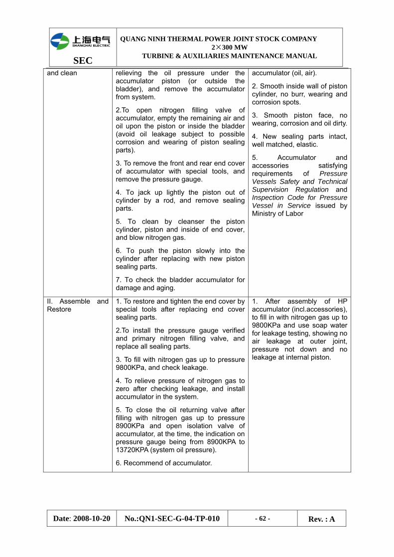
SEC
QUANG NINH THERMAL POWER JOINT STOCK COMPANY 2×300 MW
TURBINE & AUXILIARIES MAINTENANCE MANUAL
Date: 2008-10-20 No.:QN1-SEC-G-04-TP-010 - 62 - Rev. : A
and clean relieving the oil pressure under the accumulator piston (or outside the bladder), and remove the accumulator from system.
2.To open nitrogen filling valve of accumulator, empty the remaining air and oil upon the piston or inside the bladder (avoid oil leakage subject to possible corrosion and wearing of piston sealing parts).
3. To remove the front and rear end cover of accumulator with special tools, and remove the pressure gauge.
4. To jack up lightly the piston out of cylinder by a rod, and remove sealing parts.
5. To clean by cleanser the piston cylinder, piston and inside of end cover, and blow nitrogen gas.
6. To push the piston slowly into the cylinder after replacing with new piston sealing parts.
7. To check the bladder accumulator for damage and aging.
accumulator (oil, air).
2. Smooth inside wall of piston cylinder, no burr, wearing and corrosion spots.
3. Smooth piston face, no wearing, corrosion and oil dirty.
4. New sealing parts intact, well matched, elastic.
5. Accumulator and accessories satisfying requirements of Pressure Vessels Safety and Technical Supervision Regulation and Inspection Code for Pressure Vessel in Service issued by Ministry of Labor
II. Assemble and Restore
1. To restore and tighten the end cover by special tools after replacing end cover sealing parts.
2.To install the pressure gauge verified and primary nitrogen filling valve, and replace all sealing parts.
3. To fill with nitrogen gas up to pressure 9800KPa, and check leakage.
4. To relieve pressure of nitrogen gas to zero after checking leakage, and install accumulator in the system.
5. To close the oil returning valve after filling with nitrogen gas up to pressure 8900KPa and open isolation valve of accumulator, at the time, the indication on pressure gauge being from 8900KPA to 13720KPA (system oil pressure).
6. Recommend of accumulator.
1. After assembly of HP accumulator (incl.accessories), to fill in with nitrogen gas up to 9800KPa and use soap water for leakage testing, showing no air leakage at outer joint, pressure not down and no leakage at internal piston.
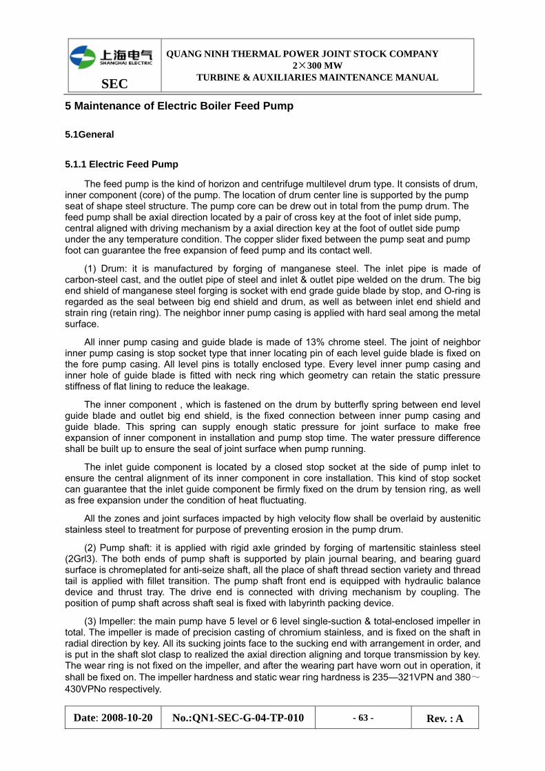
SEC
QUANG NINH THERMAL POWER JOINT STOCK COMPANY 2×300 MW
TURBINE & AUXILIARIES MAINTENANCE MANUAL
Date: 2008-10-20 No.:QN1-SEC-G-04-TP-010 - 63 - Rev. : A
5 Maintenance of Electric Boiler Feed Pump
5.1General
5.1.1 Electric Feed Pump
The feed pump is the kind of horizon and centrifuge multilevel drum type. It consists of drum, inner component (core) of the pump. The location of drum center line is supported by the pump seat of shape steel structure. The pump core can be drew out in total from the pump drum. The feed pump shall be axial direction located by a pair of cross key at the foot of inlet side pump, central aligned with driving mechanism by a axial direction key at the foot of outlet side pump under the any temperature condition. The copper slider fixed between the pump seat and pump foot can guarantee the free expansion of feed pump and its contact well.
(1) Drum: it is manufactured by forging of manganese steel. The inlet pipe is made of carbon-steel cast, and the outlet pipe of steel and inlet & outlet pipe welded on the drum. The big end shield of manganese steel forging is socket with end grade guide blade by stop, and O-ring is regarded as the seal between big end shield and drum, as well as between inlet end shield and strain ring (retain ring). The neighbor inner pump casing is applied with hard seal among the metal surface.
All inner pump casing and guide blade is made of 13% chrome steel. The joint of neighbor inner pump casing is stop socket type that inner locating pin of each level guide blade is fixed on the fore pump casing. All level pins is totally enclosed type. Every level inner pump casing and inner hole of guide blade is fitted with neck ring which geometry can retain the static pressure stiffness of flat lining to reduce the leakage.
The inner component , which is fastened on the drum by butterfly spring between end level guide blade and outlet big end shield, is the fixed connection between inner pump casing and guide blade. This spring can supply enough static pressure for joint surface to make free expansion of inner component in installation and pump stop time. The water pressure difference shall be built up to ensure the seal of joint surface when pump running.
The inlet guide component is located by a closed stop socket at the side of pump inlet to ensure the central alignment of its inner component in core installation. This kind of stop socket can guarantee that the inlet guide component be firmly fixed on the drum by tension ring, as well as free expansion under the condition of heat fluctuating.
All the zones and joint surfaces impacted by high velocity flow shall be overlaid by austenitic stainless steel to treatment for purpose of preventing erosion in the pump drum.
(2) Pump shaft: it is applied with rigid axle grinded by forging of martensitic stainless steel (2Grl3). The both ends of pump shaft is supported by plain journal bearing, and bearing guard surface is chromeplated for anti-seize shaft, all the place of shaft thread section variety and thread tail is applied with fillet transition. The pump shaft front end is equipped with hydraulic balance device and thrust tray. The drive end is connected with driving mechanism by coupling. The position of pump shaft across shaft seal is fixed with labyrinth packing device.
(3) Impeller: the main pump have 5 level or 6 level single-suction & total-enclosed impeller in total. The impeller is made of precision casting of chromium stainless, and is fixed on the shaft in radial direction by key. All its sucking joints face to the sucking end with arrangement in order, and is put in the shaft slot clasp to realized the axial direction aligning and torque transmission by key. The wear ring is not fixed on the impeller, and after the wearing part have worn out in operation, it shall be fixed on. The impeller hardness and static wear ring hardness is 235—321VPN and 380~430VPNo respectively.
SEC
QUANG NINH THERMAL POWER JOINT STOCK COMPANY 2×300 MW
TURBINE & AUXILIARIES MAINTENANCE MANUAL
Date: 2008-10-20 No.:QN1-SEC-G-04-TP-010 - 64 - Rev. : A
(4) Balance device: the hydraulic balance device of the water pump mainly consist of equilibrium drum on shaft and throttling lining on big end shield. The equilibrium drum is equipped behind the end level impeller of shaft. It is aligned in radial direction by key , and in axial direction by fillet and tightened by nut, which can balance the axial thrust arisen from pump running.
(5) Bearing:
① Radial bearing: the pump has a pair of common column type plain journal bearing. Its sliding surface is cast by Babbitt, and the bearing is mounted at the both ends of pump shaft , fixed by bearing cover, forced lubricated and cooled by pressure oil. The bearing cover is fixed on the lower half bearing frame by bolt, the all components are aligned by pin.
② Thrust bearing: it is the self position tile type structure located in the chamber of radial bearing of free end, which can aligned in axial direction for rotor, and endure double thrust to adequate for two direction rotation.
The thrust bearing consists of the components including thrust tray on shaft, tile and support ring located in bearing body of free end etc. The tile is equably located among the every individual keeper, whose outside diameter embedded in support ring flange, and can freely incline in operation by the keeper head embedded in both-side groove. The thrust bearing tile is equipped with resistance thermometer sensor to monitor alarm and tripping.
(6) Shaft end seal: the labyrinth packing of seal water down loading type with fixing lining injected is equipped on the pump. This seal is laid out parallel with single diameter. The fixing lining is the saw tooth hole type, or reverse double-head spiral flute processed respectively by seal shaft liner and lining. In pump running, the seal water shall not enter the pump and feeder for pump also shall no leakage. The seal water shall flow from annular seal space to inner pump, and meet with feed water of discharge outside at the place of down loading ring, then come back to the fore pump inlet by return pipe.
(7) Support of pump: its support adopts the rolled steel and welding connection structure, arranged at the location of center line to support water pump. The pump foot at the side of pump inlet shall be fixed on the pump seat by bolt.
5.1.2 Booster Pump
The booster pump is the kind of horizontal double-suction & single-stage & double-volute pump. Its static part includes the components such as volute pump casing, bearing seat, bearing seat end shield, mechanical seal casing, casing wear ring etc. Its rotated part includes the pump shaft, shaft liner, mechanical seal shaft liner, roller bearing etc.
(1) Casing: it is made of carbon-steel casting, double volute & middle opening type. Its inlet and outlet water pipe is located at the lower half casing which is supported by the pump seat of box-type structure through pump foot. The joint surface between casing and pump seat is near to axis center line, and its central alignment of vertical and transverse in thermal expansion slide is guaranteed by vertical pin and transverse pin.
(2) Impeller: it is the stainless steel casting with double suction structure to reach the basic balance of axial force, and the rest axial force is supported by rolling thrust bearing mounted on free end.
The impeller is fixed on the pump shaft by key, and its axial alignment shall be implemented by both sides compression nuts, and be aligned at the center location relative to casing by rolling thrust bearing.
(3) Impeller seal ring: to prevent the water exit steam return back to suction joint from the gap between impeller and casing, the seal ring, which is mounted in casing cavity and aligned by anti-rotating fixed pin, is equipped respectively at the two of suction joints
SEC
QUANG NINH THERMAL POWER JOINT STOCK COMPANY 2×300 MW
TURBINE & AUXILIARIES MAINTENANCE MANUAL
Date: 2008-10-20 No.:QN1-SEC-G-04-TP-010 - 65 - Rev. : A
(4) Pump shaft: it is made by grinding of stainless steel precision forging with stress removed, and supported by roller bearing. Its drive end is connected with electric motor by coupling. At the position of pump shaft crossing the shaft seal, the mechanical seal device is mounted.
(5) Bearing: the roller and rolling bearing is installed on the two ends of pump shaft to support the radial direction and axial direction position of rotor and fixed rotor. It is lubricated by thin oil and equipped with the cooling water chamber and temperature measurement point.
(6) Shaft seal: the mechanical seal is mounted on the pump. It belongs to balance type, and consist of moving ring supported by spring and static ring of cooling water. The separated stuffing box is mounted with water jacket so as to reduce surrounding temperature of mechanical seal rotating section.
(7) Coupling: the pile type coupling between pump and motor is the metal pipe type structure accompanied with flexibility and twisting hardness.
5.1.3 Hydraulic Coupling
The unit can implement the stepless speed regulation between water pump and electric motor. Its hydraulic coupler shall merger the coupler main body, a pair of increasing gear, working oil and lubricant pipeline into a same tank. The tank body bottom is oil tank that make the tank body and oil tank into a whole.
The coupler input shaft is connected with motor, and the output shaft connected with feeder pump by gear coupling. The rotate speed of input shaft can speed up by a pair of increasing gear and then pass to impeller shaft. The torque transmission between the impeller and the turbine is implemented by fluid dynamics of working oil.
The impeller accelerates the working oil which is delayed in the turbine so as to produce a equal torque. When there is a pressure difference in the fluid of the impeller and the turbine, the working oil circulate shall flow, so that , the rotate speed of turbine must be below that of impeller. The output rotate speed through adjusting the position of scoop tube can change the oil-filling amount in working space between the impeller and the turbine to realize the stepless speed changing.
5.2 Basic Parameters of Feed Pump
Three sets of electric feed pump will be applied in this Unit, and basic parameters are listed in the following table:
Items Unit Designed
Booster Pump – Inlet Flow t/h 626.9
Booster Pump – Inlet Pressure MPa(a) 1.1007
Booster Pump – Inlet Feedwater Temperature oC 176.5
Booster Pump – Head Rise mH2O 110
Booster Pump - Speed rpm 1490
Booster Pump – Shaft Power kW 239.3
Booster Pump - Necessary Cavitations Margin (NPSH Required) m 3.0
Booster Pump – Bearing Cooling Water t/h 4.2
SEC
QUANG NINH THERMAL POWER JOINT STOCK COMPANY 2×300 MW
TURBINE & AUXILIARIES MAINTENANCE MANUAL
Date: 2008-10-20 No.:QN1-SEC-G-04-TP-010 - 66 - Rev. : A
Feed Pump – Inlet Flow Rate t/h 626.9
Feed Pump – Inlet Pressure MPa(a) 2.062
Feed Pump – Inlet Feedwater Temperature oC 176.5
Feed Pump – Outlet Flow Rate t/h 546.9
Feed Pump – Head Rise mH2O 2136.0
Feed Pump – Outlet Pressure MPa(a) 20.72
Feed Pump - Efficiency % 81.0
Feed Pump - Speed rpm 6350
Feed Pump – Shaft Power kW 4214.9
Feed Pump - Necessary Cavitations Margin (NPSH Required) m 60.0
Pump Set Total – Total Efficiency % 75.8
Pump Set – Total Shaft Power (Incl. Coupling) kW 4747.3
5.3 Maintenance of Booster Pump
Items Technology and Notices Quality Standard
I. Preparation before Dismantling
1.Check isolation measures for operation being satisfactory or not;
2. Open water discharge valve and empty the pump.
3. Remove oil relief piston of bearing, and discharge oil in bearing seat.
4. Dismantle all instruments and piping influencing dismantling of pump set.
5. Check all lifting devices and special inspection tools.
II. Dismantling of Pump
1.Driving end bearing and mechanical seal:
(1) Dismantle coupling protection enclosure and temperature testing elements, remove coupling bolts, and take down folding pieces.
(2) Dismantle nut fixed on coupling, and use special tools to remove lower half coupling, and take down key on it.
All components must be cleaned carefully after dismantling, and placed in order for inspection and measurement.
SEC
QUANG NINH THERMAL POWER JOINT STOCK COMPANY 2×300 MW
TURBINE & AUXILIARIES MAINTENANCE MANUAL
Date: 2008-10-20 No.:QN1-SEC-G-04-TP-010 - 67 - Rev. : A
(3) Dismantle locking nut and washer on outer sleeve at driving end, bolts between bearing pedestal and end cover, bolts and locating pin between bearing pedestal and pump body, and take down bearing pedestal and roller bearing outer circle.
(4)Dismantle outer sleeve at driving end, roller bearing inner circle, end cover of bearing pedestal and inner sleeve at driving end.
(5) Dismantle mechanical seal cover at driving end and connection screw on seal cooling shell, locking screw on mechanical seal sleeve, and slide the mechanical seals out through shaft.
2. Free end bearing and mechanical seal:
(1) Dismantle bearing temperature testing elements;
(2) Dismantle bolts and end cover between free end bearing pedestal and end cover, bolts between bearing pedestal and pedestal end cover, as well as bolts between bearing pedestal and pump body, and last dismantle bearing pedestal.
(3)Dismantle outer circle of outside roller bearings and diaphragm circle between bearings.
(4) Dismantle bearing locking bolts and washer, remove inner circle of outside roller bearing and inner& outer circle of inner side roller bearing, end cover and sleeve of bearing pedestal.
(5) Dismantle connection bolts of mechanical seal cove and seal cooling shell, locking screw on mechanical seal sleeve, and slide mechanical seal out through shaft.
3. Draw out locating pin on pump and pump cover, remove fastening nut.
4. Dismantle connection bolts between seal cooling shell at both ends and pump shell.
5. Jack up pump cover by jack up
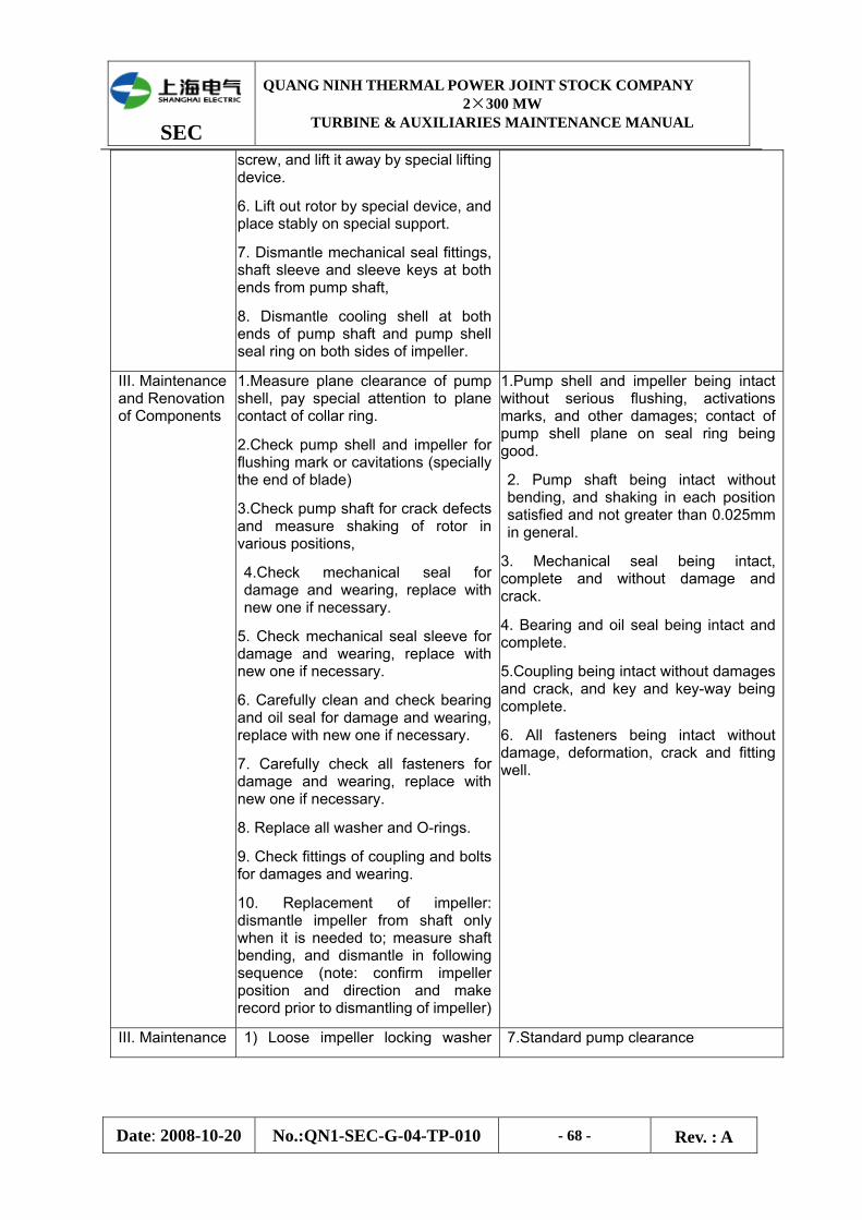
SEC
QUANG NINH THERMAL POWER JOINT STOCK COMPANY 2×300 MW
TURBINE & AUXILIARIES MAINTENANCE MANUAL
Date: 2008-10-20 No.:QN1-SEC-G-04-TP-010 - 68 - Rev. : A
screw, and lift it away by special lifting device.
6. Lift out rotor by special device, and place stably on special support.
7. Dismantle mechanical seal fittings, shaft sleeve and sleeve keys at both ends from pump shaft,
8. Dismantle cooling shell at both ends of pump shaft and pump shell seal ring on both sides of impeller.
III. Maintenance and Renovation of Components
1.Measure plane clearance of pump shell, pay special attention to plane contact of collar ring.
2.Check pump shell and impeller for flushing mark or cavitations (specially the end of blade)
3.Check pump shaft for crack defects and measure shaking of rotor in various positions,
4.Check mechanical seal for damage and wearing, replace with new one if necessary.
5. Check mechanical seal sleeve for damage and wearing, replace with new one if necessary.
6. Carefully clean and check bearing and oil seal for damage and wearing, replace with new one if necessary.
7. Carefully check all fasteners for damage and wearing, replace with new one if necessary.
8. Replace all washer and O-rings.
9. Check fittings of coupling and bolts for damages and wearing.
10. Replacement of impeller: dismantle impeller from shaft only when it is needed to; measure shaft bending, and dismantle in following sequence (note: confirm impeller position and direction and make record prior to dismantling of impeller)
1.Pump shell and impeller being intact without serious flushing, activations marks, and other damages; contact of pump shell plane on seal ring being good.
2. Pump shaft being intact without bending, and shaking in each position satisfied and not greater than 0.025mm in general.
3. Mechanical seal being intact, complete and without damage and crack.
4. Bearing and oil seal being intact and complete.
5.Coupling being intact without damages and crack, and key and key-way being complete.
6. All fasteners being intact without damage, deformation, crack and fitting well.
III. Maintenance 1) Loose impeller locking washer 7.Standard pump clearance
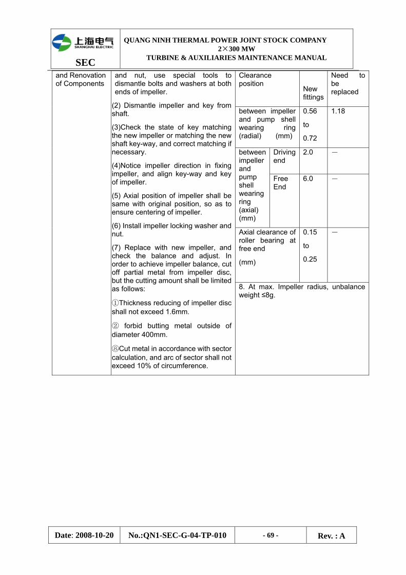
SEC
QUANG NINH THERMAL POWER JOINT STOCK COMPANY 2×300 MW
TURBINE & AUXILIARIES MAINTENANCE MANUAL
Date: 2008-10-20 No.:QN1-SEC-G-04-TP-010 - 69 - Rev. : A
Clearance position
New fittings
Need to be replaced
between impeller and pump shell wearing ring (radial) (mm)
0.56
to
0.72
1.18
Driving end
2.0 - between impeller and pump shell wearing ring (axial) (mm)
Free End
6.0 -
Axial clearance of roller bearing at free end
(mm)
0.15
to
0.25
-
and Renovation of Components
and nut, use special tools to dismantle bolts and washers at both ends of impeller.
(2) Dismantle impeller and key from shaft.
(3)Check the state of key matching the new impeller or matching the new shaft key-way, and correct matching if necessary.
(4)Notice impeller direction in fixing impeller, and align key-way and key of impeller.
(5) Axial position of impeller shall be same with original position, so as to ensure centering of impeller.
(6) Install impeller locking washer and nut.
(7) Replace with new impeller, and check the balance and adjust. In order to achieve impeller balance, cut off partial metal from impeller disc, but the cutting amount shall be limited as follows:
①Thickness reducing of impeller disc shall not exceed 1.6mm.
② forbid butting metal outside of diameter 400mm.
⑧Cut metal in accordance with sector calculation, and arc of sector shall not exceed 10% of circumference.
8. At max. Impeller radius, unbalance weight ≤8g.
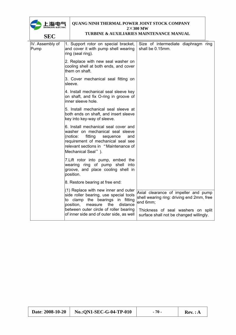
SEC
QUANG NINH THERMAL POWER JOINT STOCK COMPANY 2×300 MW
TURBINE & AUXILIARIES MAINTENANCE MANUAL
Date: 2008-10-20 No.:QN1-SEC-G-04-TP-010 - 70 - Rev. : A
Size of intermediate diaphragm ring shall be 0.15mm.
IV. Assembly of Pump
1. Support rotor on special bracket, and cover it with pump shell wearing ring (seal ring).
2. Replace with new seal washer on cooling shell at both ends, and cover them on shaft.
3. Cover mechanical seal fitting on sleeve.
4. Install mechanical seal sleeve key on shaft, and fix O-ring in groove of inner sleeve hole.
5. Install mechanical seal sleeve at both ends on shaft, and insert sleeve key into key-way of sleeve.
6. Install mechanical seal cover and washer on mechanical seal sleeve (notice: fitting sequence and requirement of mechanical seal see relevant sections in “Maintenance of Mechanical Seal”).
7.Lift rotor into pump, embed the wearing ring of pump shell into groove, and place cooling shell in position.
8. Restore bearing at free end:
(1) Replace with new inner and outer side roller bearing, use special tools to clamp the bearings in fitting position, measure the distance between outer circle of roller bearing of inner side and of outer side, as well
Axial clearance of impeller and pump shell wearing ring: driving end 2mm, free end 6mm;
Thickness of seal washers on split surface shall not be changed willingly.
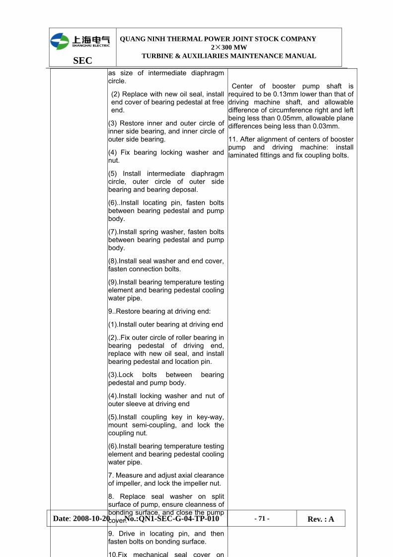
SEC
QUANG NINH THERMAL POWER JOINT STOCK COMPANY 2×300 MW
TURBINE & AUXILIARIES MAINTENANCE MANUAL
Date: 2008-10-20 No.:QN1-SEC-G-04-TP-010 - 71 - Rev. : A
as size of intermediate diaphragm circle.
(2) Replace with new oil seal, install end cover of bearing pedestal at free end.
(3) Restore inner and outer circle of inner side bearing, and inner circle of outer side bearing.
(4) Fix bearing locking washer and nut.
(5) Install intermediate diaphragm circle, outer circle of outer side bearing and bearing deposal.
(6)..Install locating pin, fasten bolts between bearing pedestal and pump body.
(7).Install spring washer, fasten bolts between bearing pedestal and pump body.
(8).Install seal washer and end cover, fasten connection bolts.
(9).Install bearing temperature testing element and bearing pedestal cooling water pipe.
9..Restore bearing at driving end:
(1).Install outer bearing at driving end
(2)..Fix outer circle of roller bearing in bearing pedestal of driving end, replace with new oil seal, and install bearing pedestal and location pin.
(3).Lock bolts between bearing pedestal and pump body.
(4).Install locking washer and nut of outer sleeve at driving end
(5).Install coupling key in key-way, mount semi-coupling, and lock the coupling nut.
(6).Install bearing temperature testing element and bearing pedestal cooling water pipe.
7. Measure and adjust axial clearance of impeller, and lock the impeller nut.
8. Replace seal washer on split surface of pump, ensure cleanness of bonding surface, and close the pump cover.
9. Drive in locating pin, and then fasten bolts on bonding surface.
10.Fix mechanical seal cover on
Center of booster pump shaft is required to be 0.13mm lower than that of driving machine shaft, and allowable difference of circumference right and left being less than 0.05mm, allowable plane differences being less than 0.03mm.
11. After alignment of centers of booster pump and driving machine: install laminated fittings and fix coupling bolts.
SEC
QUANG NINH THERMAL POWER JOINT STOCK COMPANY 2×300 MW
TURBINE & AUXILIARIES MAINTENANCE MANUAL
Date: 2008-10-20 No.:QN1-SEC-G-04-TP-010 - 72 - Rev. : A
V. Mechanical Sealing
1. Dismantling of seal parts:
(1) Press spring when dismantle the seal parts, to eliminate the pressure imposed on flexible snap ring by spring.
(2) place flat and smooth spacer on surface of seal parts, to prevent damage, then slightly press the spring of seal pieces, and insert tools with sharp point into small hole or groove on bearing pedestal.
1.Dismantling of seal parts:
(1) In dismantling seal parts, pay attention to concentricity of spring.
⑤Clean working surface and hole on seal cover, and working surface being smooth without wearing.
⑥O-ring of sleeve being intact, no water impressing of sleeve hole after O-ring fitting.
(2) Installation procedures:
① O-ring used for mechanical seal shall not be stained with oil, and liquid soap will be made as lubricant during installation.
②Set up sleeve on clamp desk, with driving pin approaching to surface of desk.
③ Install O-ring inside lubricating seal device and seal device on shaft sleeve.
Note: only slight pushing of seal device by hand for installation is allowed to prevent dynamic ring damaged.
④Driving pin shall project out of sleeve 8mm, and align with opening at back of dynamic ring support, and push seal device to make it against protruding shoulder of sleeve.
⑤Place O-ring of sleeve into sleeve groove, and cover the sleeve (together with seal device) on pump shaft; after positioning of sleeve, fix the sleeve on shaft by flat head screw.
Note: head of flat head screw is not allowed to project out of outer surface of sleeve.
⑥Place static ring positioning pin into mechanical seal cover pin hole, and mark on front of seal cover in line with pin. Mark on diameter of static ring and align the ring with pin groove, embed the radial and axial O-ring of seal cover chamber, an then fit the static ring into the seal cover chamber in accordance
Distance being between 6mm and 12mm.
Measurement before installation:
1) Allowable diameter deviation 土 0.5mm; ellipticity deviation not greater than 0.025mm;
Sleeve surface precision: is 0..4~0.6µm
2)being within 0.08mm of working position of pump shaft.
3) Deviation of verticality being less than0.03mm.
4) Deviation of concentricity being less than 0.05mm.
SEC
QUANG NINH THERMAL POWER JOINT STOCK COMPANY 2×300 MW
TURBINE & AUXILIARIES MAINTENANCE MANUAL
Date: 2008-10-20 No.:QN1-SEC-G-04-TP-010 - 73 - Rev. : A
with marks previously made.
⑦Confirm the installation position of fittings on mechanical seal cover bard, and fasten with uniform strength the connection bolts.
Note: when getting through shaft in installation of seal cover board, in order to prevent contact of static ring and shaft, the fastening on connection bolts shall be even, or else deformation on dynamic and static ring working face will be caused.
⑧ After installation, turn pump shaft in original turning direction, flexibly and freely.

SEC
QUANG NINH THERMAL POWER JOINT STOCK COMPANY 2×300 MW
TURBINE & AUXILIARIES MAINTENANCE MANUAL
Date: 2008-10-20 No.:QN1-SEC-G-04-TP-010 - 74 - Rev. : A
5.4 Maintenance of Feed Pump
Items Technology and Notices Quality Standard
I. Preparation before Dismantling
1. Cut off all power supply to motor, lubrication system and all instrumentation.
2. Close pump inlet and outlet valves, recirculation valve and isolation cooling water supply.
3. Close intermediate tap valve, open pump relief valve, and empty water inside pump.
4. Dismantle all instruments and piping from bearing pedestal and shaft gland of driving end and of free end that may influence pump dismantling.
5. Dismantle return water piping of balance chamber and bearing lubrication oil piping.
6. Check all lifting equipments and special inspection tools.
II. Dismantling of Pump
Tighten core package, place channel steel support plate on pump seat, fix the roller jack component on the pump seat to adjust height, then make it contact with disassembly tube and put its lug on the big end cover to tie up the rope so as to raise the hook slowly to strain the rope sling. The jack screw shall jack up the core package plate out of each shelves stop, and then sequentially jack out the core package until come into contact with safety locating ring.
(6) Firmly suspend locating ring by overhead crane, then meet the big end cover lug with one rope end and meet the disassembly tube with another rope end for two ends of carrying pole until it reaches the safety locating ring. Unceasingly link up the disassembly tube, and change the position of safety locating ring, screw up the setscrew and then shift out of the core package step by step until the first level disassembly tube have exposed its drum, lastly put the core package on the body support to ensure its stability and then wedge it firmly.
(7)Install the lug at the place of inlet end cover, then suspend the core package with overhead crane to make the rope A set on the drum bolt and second section of disassembly tube, suspend the dismantling component and remove the first & second sections of disassembly tube. Lastly suspend out the core package and put it on the wood frame to wedge firmly.
2.Disassembly of core package:
1) Preparation for disassembly:
①Loosen off the detaching tool, suspend tool and lug
SEC
QUANG NINH THERMAL POWER JOINT STOCK COMPANY 2×300 MW
TURBINE & AUXILIARIES MAINTENANCE MANUAL
Date: 2008-10-20 No.:QN1-SEC-G-04-TP-010 - 75 - Rev. : A
from the core package, fit on the core package clamping piece to make it cling to the inlet end cover, pass through the hole of big end cover by 4 double threaded screw slide rods and then screw it into the thread hole on the support plate, lastly screw up the clamp nut to cling to clamping piece.
②Put on the gasket at the another end of slide rod, and screw in the nut to fasten the core package component.
③Mount the lug on the big end cover by bolt and nut gasket.
Attention: in the process of core package disassembly, it shall be supported steadily, at first the disassembly is carried out at the horizontal position, at last the core package is supported vertically and its weight shall not be supported by pump shaft.
2) Disassembly of drive end bearing and shaft seal:
①Remove the fasten bolt and nut of drive end bearing cover and inlet end.
②Loosen off the clamp nut from the double armed bolt between lower bearing cover and bearing frame, and remove the alignment pin.
③Fix up the suspension ring on the bearing cover, and jack out the bearing cover by jack screw to suspend out the cover.
Attention: it shall be cautious for suspend to avoid damage the oil deflector.
④Remove the clamp nut on the double end bolt between radial bearing cover and bearing frame, loosen off the alignment pin, jack up the bearing gland by jack screw then remove the bearing gland.
⑤Remove the upper half radial bearing and oil deflector, then jack up the shaft , lastly screw and then remove the lower half radial bearing and oil deflector
⑥Remove the fastening bolt, nut and alignment pin from bearing frame, then loosen off the bearing seat frame of drive end.
⑦Make the position of throw ring on the shaft, then loose the set screw, last remove the throw ring from shaft.
⑧Remove the fasten bolt of drive end bearing plate, and loosen off the drive end bearing plate
⑨Screw out the locknut and water deflector nut of drive end by special tool (the bearing end is left-hand thread)
⑩Remove the fasten bolt of seal lining, then loosen off
SEC
QUANG NINH THERMAL POWER JOINT STOCK COMPANY 2×300 MW
TURBINE & AUXILIARIES MAINTENANCE MANUAL
Date: 2008-10-20 No.:QN1-SEC-G-04-TP-010 - 76 - Rev. : A
the seal lining, and pull out the seal shaft liner by special tool
3) Disassembly of radial bearing, thrust bearing and bearing seal of free end:
①Remove the fasten screw of bearing end cover, loosen off the end cover and O-ring.
②Remove the double end bolt and nut between bearing cover and frame, and loosen off the alignment pin.
③Remove the fasten bolt and nut between bearing cover and big end cover.
④Fit on the lug ring on bearing cover, jack up the bearing cover with jack screw, mount the suspend tool to suspend out the bearing cover.
Attention: it shall be caution that prevent damage oil deflector in hoist.
⑤Remove the alignment pin, as well as clamp nut on the double end bolt between radial bearing gland and frame, and then loosen off the bearing gland.
⑥Remove the upper half radial bearing and oil deflector.
⑦Loosen off the fasten screw and alignment pin of thrust bearing cage, screw in the jack screw, jack up the thrust bearing cage to remove .
⑧Jack up the pump shaft, rotate the lower half radial bearing and oil deflector up to top and then remove.
II. Dismantling of Pump
⑨Loose spring and dismantle lubrication oil seal ring from lower bearing support.
⑩Loosen off the baffle nut from the fastening end cover, then remove the baffle, take off the lubricant oil seal ring and spring from the end cover groove.
Rotate thrust bearing support plate with thrust tile around shaft until the half support plate with stop pin be removed, then turn another half support plate until take it off. By the same means, remove the thrust bearing support plate at the another side of thrust tray.
Attention: before remove the thrust bearing support plate from bearing frame, the resistance probe and wire for temperature measurement on bearing shall be disconnected from outer terminal, then pass through the stuffing box gland to take out the wire.
Remove the fastening bolt, nut and alignment pin between bearing frame of free end and big end cover, then loosen off the bearing frame.
1、The tongue of lock washer on thrust tray shall be flat

SEC
QUANG NINH THERMAL POWER JOINT STOCK COMPANY 2×300 MW
TURBINE & AUXILIARIES MAINTENANCE MANUAL
Date: 2008-10-20 No.:QN1-SEC-G-04-TP-010 - 77 - Rev. : A
treated, and then loosen off the thrust tray nut by special spanner to take out the lock washer.
2、Fix the special tool for disassembly of thrust tray, then heat up its wheel hub, lastly loosen off the thrust tray and take off its key.
3、Mark the thrower position on the shaft, then loose the set screw, lastly take out the thrower from shaft.
4、Remove the bolt of free end bearing plate, then loosen off the free end bearing plate.
5、Screw out the locknut of free end and water deflector nut by special tool (the free end is right-hand thread)
6、Remove the bolt of fasten seal lining and take off the seal lining.
7、Take off the seal lining by special tool.
(4) Disassembly of inner pump shell:
①Fasten the rotor by double end screw, nut and bearing plate.
②Vertically put the core package on the holding frame.
Attention: Don’t support the core package weight by pump shaft when suspend the core package.
③Remove the nut and gasket of slide rod and big end cover, and loosen off the slide rod.
④Suspend the big end cover away from pump shaft.
Attention: Prevent damage the balance kettle and its lining when suspend the big end cover.
⑤Smooth out the stop tongue of stop-ping washer by balance kettle, loosen off the balance kettle nut and stop-ping washer.
⑥Take out the seal pressing ring and seal ring of balance kettle
⑦Fit up the special tool for disassembly of balance kettle, then heat up the balance kettle to 250℃ by flame, until it produces enough expansion, rapidly loosen off the balance kettle, as well as key and butterfly spring.
Attention: control heating temperature so as to avoid overheating
⑧Remove the lock sheet and screw between end level guide blade and pump shell, then loosen off the end level guide blade
Attention: It’s the interference fit between guide blade
SEC
QUANG NINH THERMAL POWER JOINT STOCK COMPANY 2×300 MW
TURBINE & AUXILIARIES MAINTENANCE MANUAL
Date: 2008-10-20 No.:QN1-SEC-G-04-TP-010 - 78 - Rev. : A
and pump shell.
⑨Heat up the outer margin of end level impeller by flame to 150℃, then heat up the impeller cover plate to 200-250℃ and keep it, rapidly heat the impeller wheel hub to 300℃. When the reached temperature can produce enough expansion, take off the impeller from the shaft, as well as impeller key and clasp.·
Attention: Make a mark when impeller be removed.
⑩Loosen off the fasten screw between third and fourth level inner pump shell, then remove the fourth level inner pump shell as well as O-ring and closing ring, suspend away the inner pump shell and guide blade by lug.
11、As per above-mentioned subsequence, remove the fourth impeller as well as other level impeller, inner pump shell and guide blade until only remain the first level impeller on the shaft, then take off the O-ring and sealing from the second pump shell.
Attention: The connection screw between second and third level pump shell shall be locked by lock sheet, so that, before remove these screws, the lock sheet shall be loosened off in advance.
12、Screw in the hanger shaft lug on the shaft end, then mount the hanger tool, lastly loosen off the clamp nut of drive end as well as bearing plate.
13、Suspend out the pump shaft from inlet end and horizontally put it onto special frame.
14、Heat up the first level impeller by flame(same as former heating methods and requirements), When the reached temperature can produce enough expansion, take off the impeller from the shaft, as well as impeller key.·
2. The journal ellipse degree ≤0.0lmm,
Wow flutter be less than 0.03mm,
concentricity deviation ≤0.02mm.
3. The wow flutter of impeller seal ring after rotor installed ≤0.O?mm, the journalwow flutter ≤0.04mm.
4. Impeller inner hole shall be smooth and no deformation.
5. The contact angle of plain journal bearing commonly is 45°, the contact surface shall be up to 75% and uniform distribution, the thickness error of trust tile block not be more than 0.02mm.
6. The contact surface of thrust tile shall hold the 75% of total area and be uniform distribution.

SEC
QUANG NINH THERMAL POWER JOINT STOCK COMPANY 2×300 MW
TURBINE & AUXILIARIES MAINTENANCE MANUAL
Date: 2008-10-20 No.:QN1-SEC-G-04-TP-010 - 79 - Rev. : A
IV. Assembly of Pump
1. Assembly of Inner Pump Shell and Impeller:
(1) Place pump shaft horizontally on special support, and install primary impeller key.
(2) Heat impeller by flame in sequence of dismantling, and cover on shaft after impeller temperature up to certain value causing enough expansion, until closely against the shaft shoulder.
Notice: when installing impeller, align impeller key-way and key. If impeller can not be completely installed in one time, it shall be removed and checked for any burr or dirty on it, cleaned, reheated and installed again.
(3) Lift inlet end cover in position, and assembly on support platfrom.
(4) After cooling pump shaft and primary impeller to ambient temperature, fix lug of pum shaft at free end, lift vertically the
15、Suspend out the inlet end cover from special frame by lug.
(5) The error shall not be more than standard when measure the thickness of thrust tile, or the thrust bearing back plate equipped with thrust tile shall be put on a piece of flat to check planeness of the thrust tile. Mount all thrust tiles at location, then press the thrust tray to tile and then turn the rotor in order to check the contact surface of thrust tile.
(6)If rotor has changed its impeller or half coupling, the dynamic balancing test shall be carried out as per requirements, as well as following methods:
(1) Support the rotor at the center line of bearing to check its dynamic balancing is limited in 25M/n(g·m) or not, in which M is rotor mass and 2 is the original rotation speed (r/min).
(2)The dynamic balancing shall be reached by removing the metal on the impeller cover plate, but still be in following limit range:
①Any point thickness of front & back cover plate of impeller shall not be less than 6.5mm.
②Forbid to cut the metal from impeller if diameter is out of the range of 260/u290mm
III. Inspection of Pump
The metal mass shall be calculated as per sector, whose arc length shall not exceed the 1/10 of impeller perimeter.
SEC
QUANG NINH THERMAL POWER JOINT STOCK COMPANY 2×300 MW
TURBINE & AUXILIARIES MAINTENANCE MANUAL
Date: 2008-10-20 No.:QN1-SEC-G-04-TP-010 - 80 - Rev. : A
pump shaft, then place it inside end cover until impeller inlet journal completely placed into the bushing, with impeller posited on inlet end cover, and last remove such lug of pump shaft.
(5) Install guid vane on inner pump shell (interference fit).
(6) Install O-ring, retainig ring and seal parts on inner pump shell.
Note: immerse O-ring, retaining ring and seal parts in hot water approaching boiling point before installation.
(7) Lift primary inner pump shell and guide vane inside inlet end cover, align datum line of inlet end cover and inner pump shell when in lifting, and make position of location pin accurate.
(8) Tighten inner hexagon bolts for connection of inlet end cover and primary inner pump shell.
Note: screw head can not extrude out of surface of inner pump shell.
(9) Check total axial displacement in the method as follows before taking next spet for assembly:
① Fix lug at free end of pump shaft and install appropriate lifting tools.
②Lift up pump shaft and place primary impeller on inlet end cover.
⑧Mark one line on shaft by pencil with reference of primary inner pump shell surface.
④Lift up axial free end and mark the second line on shaft with the said as reference.
⑤Measure distance between two lines and get a result about 8mm (the min. allowable displacement of pump shaft 6mm).
⑥Lift down pump shaft until primary impeller placed on inlet end cover, then dismantle lifting tools and lug.
(10) Fix snap ring and key of secondary impeller at first, then install secondary impeller and rest impeller, inner pump shell and guide vane in accordance with method above said.
Note: connection screw between second stage and third stage inner pump shell must be fixed by new locking sheet.
(11) Remeasure total axial displacement to see any changes occurred (measure in the say way above said).
(12) Install and fix the last stage guide vane on last stage inner pump shell by hexagonal screw and lock by locking sheet.
(13) Heat balance drum by frame until certain temperature
SEC
QUANG NINH THERMAL POWER JOINT STOCK COMPANY 2×300 MW
TURBINE & AUXILIARIES MAINTENANCE MANUAL
Date: 2008-10-20 No.:QN1-SEC-G-04-TP-010 - 81 - Rev. : A
IV. Assembly of Pump
reached and enough expansion produced (with reference to sample), quickly install balance drum on shaft to make it against shaft shoulder, and firmly lock it by bolt nut.
(14)After balance drum cooling to ambient temperature, remove locking nut on it, install seal ring, seal pressing ring and locking washer, and restore locking nut as well as locking washer.
(15) Wring the tie-rod to support of core-cladding, and fix it by locking nut.
(16) install futterfly spring, fix control bolt and nut between last stage guide vane and big end cover, and then lift bid end cover inside.
(17) Use control bolt and nut to adjust distance between support plate and bid end cover which shall be 752mm.
(18) Fix tie-rod washer and nut, and fasten nut by turning, remove lifting devices.
(19 Install positioning device fixed at driving end;
(20) mount lug and lift core-cladding to special support in horizontal direction, and then dismantle positioning device fixed at transmission end.
2. Assembly of Shaft Gland:
(1) Replace all O-ring:
(2)Place seal boxes at free end into big end cover and fasten by bolts.
(3)Install seal bush and check completement.
(4) Fasten water ring nut by turning and lock it.
(5) Install bracket and fix by bolt.
3. Assembly of Driving End Bearing:
(1) Install O-ring of oil slinger, fix such oil slinger on shaft and make the oil nozzle being opposite to bearing, and fix by locking screw.
(2) Install the bearing pedestal of driving end on inlet end cover, fix position by location pin, and fasten the connection bolts between bearing pedestal and inlet end.
(3) Lift up shaft, place inside the lower radial bearingt and lower retaining ring, and put down shaft.
(4)Install upper radial bearing and upper radial bearing gland, fix anti-rotation pin and location pin, and then fasten bolts on bearing gland.
(5) Fix upper retaining ring.
(6)Install bearing cover of driving end, fix locating pin, and then fasten connection bolts between bearing cover and inlet
SEC
QUANG NINH THERMAL POWER JOINT STOCK COMPANY 2×300 MW
TURBINE & AUXILIARIES MAINTENANCE MANUAL
Date: 2008-10-20 No.:QN1-SEC-G-04-TP-010 - 82 - Rev. : A
end cover.
4. Assembly of Free End Bearing:
(1) Fix O-ring before oil slinger on shaft, and make the nozzle opposite to bearing, fasten by locking bolt.
(2) Install thrust disc key on shaft, heat such disc by flame to acquire certain temperature for enough expansion, quickly fix the thrust disc on shaft, and make it against the shaft shoulder, fasten the nut on shrust disc.
(3)After thrust disc cooling to ambient temperature, remove nut and place locking washer, then fasthen the nut and lock by locking washer.
(4)Install free end bearing pedestal, fix locating pin, fasten the connection bolt between bearing pedestal and bid end cover.
(5) Lift up shaft, place inside the lower radial bearing and lower retaining ring, lubrication seal ring and spring, and then lift down the pump shaft.
6)Place half supporting plate excluding locating pin on the shaft, make the thrust pad surface contact with thrust disc, and turn it into support, place the other half supporting plate on and turn the whole thrust bearing supporting plate around the shaft, until the locating pin going against bearing support. Install the supporting plate on the other side in the same way.
Note: angle between combining line of thrust bearing supporting plate and level of bearing bracket shall be 90 degree, locating pin posited inside bearing bracket.
Resistence temperature measuring probe is to insert into thrust pad and fix on thrust being supporting plate, when in assembling thrust bearing supporting plate, fix probe in position prior to fixing seal, and conductor will go through bearing bracket and seal ring and return to the terminal.
(7) Install bearing end cover, fasten bolts for connection of end cover and bearing frame.
(8) Check axial bearing. Make shaft approach driving end in inspection, enable the thrust disc closely attaached to inner side thrust pad, mesure clearance between outer side thrust bearing supporting plate washer (adjustment washer) and end cover.
Note: feeler gauge can not be inserted into middle space between thrust pad and disc for clearance mesuring purpose, to preven damaging pad surface.
SEC
QUANG NINH THERMAL POWER JOINT STOCK COMPANY 2×300 MW
TURBINE & AUXILIARIES MAINTENANCE MANUAL
Date: 2008-10-20 No.:QN1-SEC-G-04-TP-010 - 83 - Rev. : A
(9) Install thrust bearing enclosure, drive locating pin, fasten connection bolts between bearing enclosure and bearing bracket.
(10) install upper half radial bearing and upper cover, drive bearign anti-turning pin, and fasten connection bolts between bearing and bearing bracket.
(11) Install upper oil retaining ring, and then bearing cover, drive locating pin, and fasten connection bolts of bearing cover and bearing bracket.
(12) Embed lubricating oil seal ring in groove of end cover, fix spring, and fix baffle on end cover by screw to clamp seal ring.
5.Placing core-cladding into cylinder:
(1) Fix disassemblng plate by bolt on bearing support at transmission end, turning frist stage dismantling tube inside, install tightening bolt and pressing plate, fastening nut.
Note: core-cladding can not be tensioned too much, only for elimination of clearance.
(2) Dismantle control bolt and tie-rod on core-cladding, and remove supporting plate of core-cladding from inlet end.
(3)Embed O-ring in big end cover and circumference groove of inlet end cover, and install copperized low carbon connection washer on contact surface of inlet end cover and cylinder.
Note: seal ring retainer of inlet end cover must be fixed on inlet side of O-ring.
(4)Fix ring and lug on big end cover and inlet end cover, lift core-cladding by overhead crane to assembling yard, and fix second stage dismantling tube on it.
(5) Fix channel steel supporting plate and movable cylinder jackup components on pump seat, and move core-cladding into cylinder to make the tube placed over cylinder jackup components..
(6) Remove lug on inlet end cover, connect shoulder pole with rope firmly on overhead crane, one rope end on lug of big end cover, and the other end on dismantling tube, make the shoulder pole and core-cladding be level.
(7) Slowly push corep-cladding into cylinder, until first stage dismantling tube being posited on cylinder jackup components, and dismantle second stage dismantling tube.
(8) Adjust jackup components, align center of pump, and continuously push the core-cladding into cylinder, until fully fix double-head bolt on end cover.
SEC
QUANG NINH THERMAL POWER JOINT STOCK COMPANY 2×300 MW
TURBINE & AUXILIARIES MAINTENANCE MANUAL
Date: 2008-10-20 No.:QN1-SEC-G-04-TP-010 - 84 - Rev. : A
Note: when pushing core-cladding into cylinder, ensure centering of core-cladding and cylinder, and prevent damage of O-ring and seal parts.
(9) Dismantle lifting ring on end cover as big end cover closely sticked to cylinder.
(10) Dismantle jackup components and channel steel supporting plate from driving end.
(11) Remove washers and nuts fixing pressing plate from shaft end, and take down pressing plate.
(12) Remove first stage dismantling tube and screw fixing dismantling plate, and take down such plate.
(13) Fasten nut of connection bolt for big end cover and cylinder by hand.
(14) Fasten nut by bolt hydraulic stretching device in the following sequence:
① Place hydraulic stretching devcie on double-head bolts in opposite position, fsthen the bolt cylinder by hand and make the frame closely attach to bid end cover.
②Connect hydraulic stretching devcie to oil manifold by hose, and fill oil of system.
③ Increase oil pressure of system to 50MPa, and fasten big nut by turning rod.
④Operate the valve on booster pump, relief the oil pressure o system, disconnet oil pipe, remove hydraulic stretching device, and fasten all big nut by hydraulic stretching device in accordance with above-said sequence.
⑤Increase oil pressure up to 80MPa (for M52*3 bolt) or 75MPa (for M48*3 bolt), and fasten each big nut in accordance with above-said sequence.
(15) Install big bolt proction cover, and fix O-ring and ring baffle between inlet end and big cylinder.
(16) Fix interconnection washer of retaining ring, and then put the ring in groove of inlet end cover and big cylinder, fasten the connection bolt between retaining ring and big cylinder.
(17) Install coupling key and cover semi-coupling.
(18) Fix coupling nut and lock it.
(19) Turn rotor, running smooth without abnormal sound.
(20) Align the centers and install protection enclosure.
(21) Install all instruments and piping dismantled prior to disassembling of pump set.
6. Assembly of Shaft Gland: 11. Install isolation spacer at outlet end,
SEC
QUANG NINH THERMAL POWER JOINT STOCK COMPANY 2×300 MW
TURBINE & AUXILIARIES MAINTENANCE MANUAL
Date: 2008-10-20 No.:QN1-SEC-G-04-TP-010 - 85 - Rev. : A
(1) Fix key of dynamic ring seat on shaft and fasten by screw, and assemble cooling body involving O-ring.
(2) Install O-ring in groove of gland seal body, and asembly gland seal body.
(3) Put O-ring in dynamic ring seat, and put dynamic ring into ring seat, cover the said on shaft and key, measure and check.
(4) Cover shaft sleeve on shaft and lock by shaft connection cap, and then install suppor bringing static ring inside seal end wall, measure and check.
(5) Assemble seal end cover bringing O-ring, and fasten by hexagon bolts.
7. Assembly of Bearing:
(1) Radial bearing:
①Assemble lower part of bearing and fix it on cooling body, lift up rotor and place down lower half bearing.
②Assemble labyrinth ring of upper bearing pad and upper bearing body at driving end, and fix bearing body by taper pin, correcting pin hole by reaming tool if necessary, mesure bearing pad clearance, fastening force and shaft lifting test, and record measured valve on special card.
①Assemble front upper bearing pad of pump, mesure bearing pad clearance and fastening force, and take down in special record card.
(2)Thrust Bearing:
①Put isolation ring into bearing body, insert force measuring ring; cylinder pin must match groove inside bearing body.
② Install sector pad, sector pad support, galdn ring retainer and O-ring on shaft, and cylinder pin must match with groove inside bearing body.
②Install isolation ring on shaft, put thrust disc in opposite to key-way on shaft and install on shaft, lock by shaft connection cap nut, and check thrust bearing clearance.
④Assemble upper bearing body with inclusion of labyrinth ring (located by taper pin), and fasten upper bearing body.
⑤ Install gland ring and retainer in front bearing cover, assemble sector pad and bearing cover, and fasten the bolt symmetrically.
⑥ Install rotor position indicator and speed indicator.
⑦ Align center of coupling, restore pump cover and lubricating oil pip on bearing body, cooling water pipe and temperature measuring elements.
ensure scale L4-L4 being within (3.2±0 2)mm scope.
12. Use isolation washer to separate wraping spacer at end cover, and old spacer being not allowed to be used again. Wraping spacer shall not be distorted, damaged and appropriately stored.
13. Elongation of bolt at end cover shall be 0.30~0.35mm.
14. Axial end cover of dynamic ring and static ring shall be bright and clean, without scratch, and spoon-shape deflection of end surface being less than 0.015mm.
15.Spring being without crack, rupture and rust, non-perpendicularity of both spring ends and center line being less than 0.5%.
16. Push rotor to suction side, mesure and calculate number of isolation washer; the number on suction side (d+e+0.35-59)÷2; the number on discharging side: (d÷e-O.35-59)+2
l 7. Washer should not be too much, in order to guarantee life cycle of mechanical seal.
1 8. Rotor center: circumference deviation not greater than 0.04mm, and plane deviation not greater than 0.04mm.
19. When in installation
SEC
QUANG NINH THERMAL POWER JOINT STOCK COMPANY 2×300 MW
TURBINE & AUXILIARIES MAINTENANCE MANUAL
Date: 2008-10-20 No.:QN1-SEC-G-04-TP-010 - 86 - Rev. : A
of mechanicle seal cooling water pump clip sleeve type connector, the fit diameter clearance between outer diameter and inner diamter of clip sleeve shall be less than 0.05mm, with matching section being straight without elliptical, and clip sleeve projecting 1mm out of tube
5.5 Maintenance of Hydaulic Coupling
Items Technology and Notices Quality Standard
I. Dismantling 1.Dismantle protection enclosure of connection between hydraulic coupler and motor as well as between coupler and feed pump.
2. Dismantle oil piping for inspection of hydraulic coupling, appropriately keep the dismantled oil piping, and prepare protection mesaures for flanges and holes on hydraulic coupling to preven foreign matters from dropping in.
3. In dismantling connectors at both ends of hydraulic coupling, remove pressure covers at both ends firstly as the coupling being serrated connection, push outer gear wheel, and remove connection bolt.
4. Dismantle meters, dial plates and temperature measuring elements on coupling.
5. Dismantle motor of governing mechanism, remove caps on dipathcing mechanism, turn off anchor bolts (4 pieces) of governing mechanism and dismantle control bar.
6. Remove connection bolt between upper and lower boxes, and dismantle outer cover of coupling thrust bearing.
7. Connect steel rope on four corners of upper box, lift such half bax to maintenance yard slowly in horizontal way, and place wooden block on bonding surface, to prevent any possible damages.
I. Speed governing meachanism and oil discharging part:
(1) Radial clearance between scoop tube and sleeve shall be 0.03~0.05mm, ,matching flexibly wihtout jam fault.
<2) Idle stroke of scoop tube inside sleeve shall be120+ 0.20mm (indication as “100”).
(3) Length of oil pilot valve shall be 23.14mm, and adjust screw until bottom legnt 38mm achieved (indication as “0”).
(4) Fit clearance between oil discharge chamber nad turbine shall be 3.54mm.
(5) Fit clearance between oil supply chamber and turbine sleeve shall be 3.14mm.
2.Clearance of bearings:
(1) Radial bearing clearance of big gear rotor (no.1 and 2) shall be 0.21~0.30mm.
(2)Radial bearing (no.5) clearance of small gear rotor shall be 0.17~0.23mm.
(3) Clearance of bearing no.6 of coupling shall be 0.12~0.17mm.
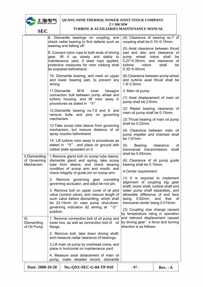
SEC
QUANG NINH THERMAL POWER JOINT STOCK COMPANY 2×300 MW
TURBINE & AUXILIARIES MAINTENANCE MANUAL
Date: 2008-10-20 No.:QN1-SEC-G-04-TP-010 - 87 - Rev. : A
8. Dismantle bearings on coupling, and check radial bearing to find defects such as wearing and falking off.
9. Connect nylon rope to both ends of driving gear, lift it up slowly and stably to maintenance yard, if steel rope applied, protective measures for rotor rubbing shall be prepared beforehand.
10. Dismantle bearing, and mark on upper and lower bearing pad, to prevent any wrong.
11.Dismantle M16 inner hexagon connection bolt between pump wheel and turbine housing, and lift rotor away in procedures as stated in “9”.
12.Dismantle bearing no.7,8 and 9, and remove bolts and pins on governing mechanism.
13.Take scoop tube sleeve from governing mechanism, but mesure distance of oil spray nozzles beforehand.
14. Lift turbine rotor away in procedures as stated in “9”, and place on ground with rubber plate spreaded on it.
II.Dismantling of Governing Mechanism
1.Remove gland bolt on scoop tube sleeve, dismantle gland and spring, take scoop tube from sleeve, and check wearing condition of scoop arm and mouth, and check integrity of guide pin on scoop arm.
2. Remove governing gear conneting governing acctuator, and adjut tie-rod pin.
3. Remove bolt on upper cover of oil pilot valve (control valve), and mesure length of such valve before dismantling, which shall be 23.14mm (in case pump shut-down, governing indication d2 aiming at “O” positoin.
III. Dismantling of Oil Pump
1. Remove connection bolt of oil pump and lower box, as well as connection bolt of oil flange.
2. Remove botl, take down driving shaft, and measure radial clearance of bearings.
3.Lift main oil pump by overhead crane, and place in horizontal on maintenance yard.
4. Measure axial dislacement of main oil pump, make detailed record, dismantle
(4) Clearance of bearing no.7 of coupling shall be 0.10~0.15mm.
(5) Axial clearance between thrust pad and disc and clearance of pump wheel rotors shall be 0.27~0.35mm, and clearance of turbine rotors shall be 0.32~0.40mm.
(6) Clearance between pump wheel and turbine axial thrust shall be 1.8~2.5mm.
3. Main oil pump:
(1) Axial displacement of main oil pump shall be 2.6mm.
(2) Radial bearing clearance of main oil pump shall be 0.15mm.
(3) Thrust bearing of main oil pump shall be 0.22mm.
(4) Clearance between main oil pump impeller and chamber shall be 1.67mm.
(5) Bearing clearance of transversal transmmission shaft shall be 0.05mnm.
(6) Clearance of oil pump guide bearing shall be 0.10mm.
4.Center requirement:
(1) It is required to implement alignment of coupling big gear shaft, motor shaft, turbine shaft and water pump shaft separately, and allowable difference of end face being 0.02mm, and that of transveral center being 0.015mm.
(2) Coupling size change caused by temperature rising in operation and relevant displacement casued by driving gear’s force and turning direction is as follows:

SEC
QUANG NINH THERMAL POWER JOINT STOCK COMPANY 2×300 MW
TURBINE & AUXILIARIES MAINTENANCE MANUAL
Date: 2008-10-20 No.:QN1-SEC-G-04-TP-010 - 88 - Rev. : A
upwards from dismantling of pump inlet, and mark on each part dismantled to avoid any possible wrong.
A1 0.10 0.20Increased distance between
centers(mm) A2 0.15 0.15
B 0.30
Clockw
ise
C 0.30
B 0.35 0.50
IV. Checking and Cleaning
1. Clean and check various bearing, and detect defects, if any, eliminate immediately those that can be eliminated, or else replace with new ones.
2. Check gear meshing condition, and detect defects, such as crack and flaking off.
3. Check strainer being against foreign matter in lower oil tank, if any damages existed, carry out timely treatment.
4. Check integrity of fusible plug of turbine housing, or else replace with new ones.
5. Clean coupling oil tank, no grease stain in dead corner, and no sundries and rust spot in whereever of oil tank, and use cloth without felt for wiping.
6.Clean and check double-cylinder switchable strainer, do repairing or replacement of strainer cloth if any defects found.
7. Check all parts, ensure they satisfying quality standard, clean and prepare for assembly.
V. Oil Cooler Inspection technology and quality standard of oil cooler can refer to the section of variable oil system of unit in this Specification.
Height increased
Anti-clockw
ise
C 0.20 0.30
Length increased △L 0.80 0.70
VI. Assembly
Assembly procedures is contrary to that of dismantling, simply described as follows:
1. Install check valve, overflow valve, control valve, constant pressure valve, oil filter and oil piping inside lower oil tank.
2. Install lower part of I-5 radial bearing in position accordingly, inject a little lubrication oil.
3. Lift driving gear rotor and pump wheel rotor in position by overhead crane, pay attention to chevron gear, run for a circle, and then fix them by locating pin and bolts.
4. Combine bearing on turbine rotor and scoop tube oil discharging part together, and install the combined body on assembled oil discharge chamber of turbine
5·Main parameters in commissioning and operation:
(1) Specification for startup
① Prior to coupler startup, open auxiliary lubrication oil pump, adjust pressure of lubrication oil manifold and make the oil pressure up to 0.25MPa (adjusted by constant pressure valve). Lubrication oil pressure for various bearing shall
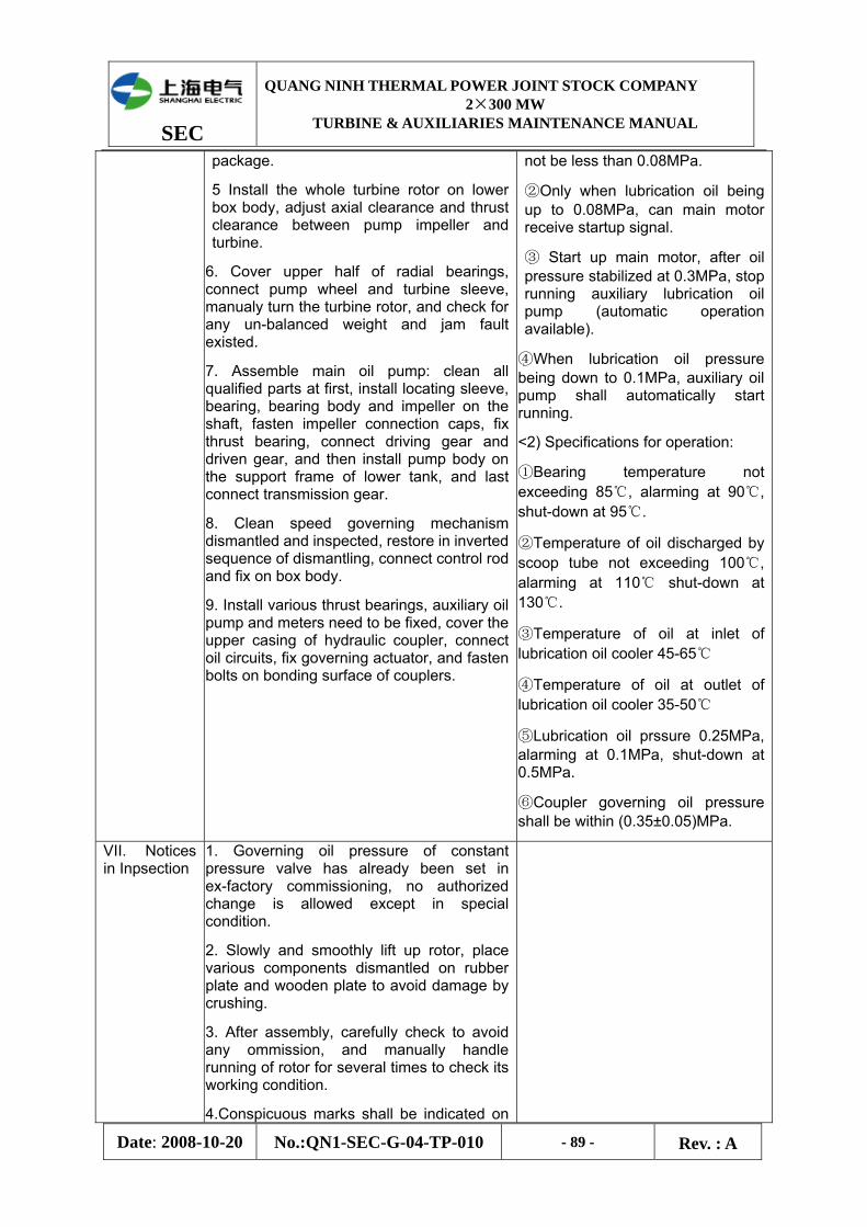
SEC
QUANG NINH THERMAL POWER JOINT STOCK COMPANY 2×300 MW
TURBINE & AUXILIARIES MAINTENANCE MANUAL
Date: 2008-10-20 No.:QN1-SEC-G-04-TP-010 - 89 - Rev. : A
package.
5 Install the whole turbine rotor on lower box body, adjust axial clearance and thrust clearance between pump impeller and turbine.
6. Cover upper half of radial bearings, connect pump wheel and turbine sleeve, manualy turn the turbine rotor, and check for any un-balanced weight and jam fault existed.
7. Assemble main oil pump: clean all qualified parts at first, install locating sleeve, bearing, bearing body and impeller on the shaft, fasten impeller connection caps, fix thrust bearing, connect driving gear and driven gear, and then install pump body on the support frame of lower tank, and last connect transmission gear.
8. Clean speed governing mechanism dismantled and inspected, restore in inverted sequence of dismantling, connect control rod and fix on box body.
9. Install various thrust bearings, auxiliary oil pump and meters need to be fixed, cover the upper casing of hydraulic coupler, connect oil circuits, fix governing actuator, and fasten bolts on bonding surface of couplers.
not be less than 0.08MPa.
②Only when lubrication oil being up to 0.08MPa, can main motor receive startup signal.
③ Start up main motor, after oil pressure stabilized at 0.3MPa, stop running auxiliary lubrication oil pump (automatic operation available).
④When lubrication oil pressure being down to 0.1MPa, auxiliary oil pump shall automatically start running.
<2) Specifications for operation:
①Bearing temperature not exceeding 85℃, alarming at 90℃, shut-down at 95℃.
②Temperature of oil discharged by scoop tube not exceeding 100℃, alarming at 110℃ shut-down at 130℃.
③Temperature of oil at inlet of lubrication oil cooler 45-65℃
④Temperature of oil at outlet of lubrication oil cooler 35-50℃
⑤Lubrication oil prssure 0.25MPa, alarming at 0.1MPa, shut-down at 0.5MPa.
⑥Coupler governing oil pressure shall be within (0.35±0.05)MPa.
VII. Notices in Inpsection
1. Governing oil pressure of constant pressure valve has already been set in ex-factory commissioning, no authorized change is allowed except in special condition.
2. Slowly and smoothly lift up rotor, place various components dismantled on rubber plate and wooden plate to avoid damage by crushing.
3. After assembly, carefully check to avoid any ommission, and manually handle running of rotor for several times to check its working condition.
4.Conspicuous marks shall be indicated on

SEC
QUANG NINH THERMAL POWER JOINT STOCK COMPANY 2×300 MW
TURBINE & AUXILIARIES MAINTENANCE MANUAL
Date: 2008-10-20 No.:QN1-SEC-G-04-TP-010 - 90 - Rev. : A
any dismantled components to avoid any wrong in assembly.
5. Clean, check and measure all components dismantled, and forbid to use those unqualified.
6. Any gauges on coupler shall be delivered to metering department for new testing, to avoid any potential error.
7. Either hydraulic transmission oil or turbine oil no.20 can be used for hydraulic coupler, and the oil quality must be guaranteed.
8. Any foreign matter shall be prevented from dropping off during inspection and assembling. Carefully check equipments and working site after assembly, so as to avoid any ommission and inadequate installation.
Attachment
Form 1 List of Carried (Commission) Spare Parts for Electric Variable Boiler Feed Pump Set (for two units)
No. Items SPEC & Type Unit Q’ty Origin Manufactory Remark
1 Seal Parts
Booster pump mechanical seal friction fittings
8B1D Set 2 EAGLE
One for respective driving end
and free end
O-slinger for oil slinger φ94.54×φ3.53 Pcs. 3 Zibo Ebara Boshan
Pump Fluororubb
er F275
O-ring for seal bush φ98.43×φ3.53 Pcs. 2 Zibo Ebara Boshan Pump
Fluororubber F275
O-ring for bid end cover φ544.82×φ6.99 Pcs. 1 Zibo Ebara Boshan
Pump Fluororubb
er F275
O-ring for seal bush φ145.34×φ3.53 Pcs. 2 Zibo Ebara Boshan Pump
Fluororubber F275
O-ring for seal box φ259.64×φ3.53 Pcs. 1 Zibo Ebara Boshan Pump
Fluororubber F275
O-ring for end cover φ265.70×φ6.99 Pcs. 1 Zibo Ebara Boshan Pump
Fluororubber F275
O-ring for end cover φ279.40×φ6.99 Pcs. 1 Zibo Ebara Boshan Pump
Fluororubber F275
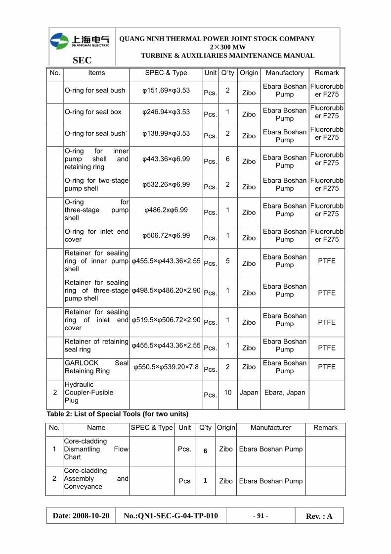
SEC
QUANG NINH THERMAL POWER JOINT STOCK COMPANY 2×300 MW
TURBINE & AUXILIARIES MAINTENANCE MANUAL
Date: 2008-10-20 No.:QN1-SEC-G-04-TP-010 - 91 - Rev. : A
No. Items SPEC & Type Unit Q’ty Origin Manufactory Remark
O-ring for seal bush φ151.69×φ3.53 Pcs. 2 ZiboEbara Boshan
Pump Fluororubb
er F275
O-ring for seal box φ246.94×φ3.53 Pcs. 1 Zibo Ebara Boshan Pump
Fluororubber F275
O-ring for seal bush` φ138.99×φ3.53 Pcs. 2 Zibo Ebara Boshan Pump
Fluororubber F275
O-ring for inner pump shell and retaining ring
φ443.36×φ6.99 Pcs. 6 Zibo Ebara Boshan Pump
Fluororubber F275
O-ring for two-stage pump shell φ532.26×φ6.99 Pcs. 2 Zibo
Ebara Boshan Pump
Fluororubber F275
O-ring for three-stage pump shell
φ486.2xφ6.99 Pcs. 1 ZiboEbara Boshan
Pump Fluororubb
er F275
O-ring for inlet end cover φ506.72×φ6.99 Pcs. 1 Zibo
Ebara Boshan Pump
Fluororubber F275
Retainer for sealing ring of inner pump shell
φ455.5×φ443.36×2.55 Pcs. 5 ZiboEbara Boshan
Pump PTFE
Retainer for sealing ring of three-stage pump shell
φ498.5×φ486.20×2.90 Pcs. 1 ZiboEbara Boshan
Pump PTFE
Retainer for sealing ring of inlet end cover
φ519.5×φ506.72×2.90 Pcs. 1 ZiboEbara Boshan
Pump PTFE
Retainer of retaining seal ring φ455.5×φ443.36×2.55 Pcs. 1 Zibo
Ebara Boshan Pump PTFE
GARLOCK Seal Retaining Ring φ550.5×φ539.20×7.8 Pcs. 2 Zibo Ebara Boshan
Pump PTFE
2 Hydraulic Coupler-Fusible Plug
Pcs. 10 Japan Ebara, Japan
Table 2: List of Special Tools (for two units)
No. Name SPEC & Type Unit Q’ty Origin Manufacturer Remark
1 Core-cladding Dismantling Flow Chart
Pcs. 6 Zibo Ebara Boshan Pump
2 Core-cladding Assembly and Conveyance
Pcs 1 Zibo Ebara Boshan Pump
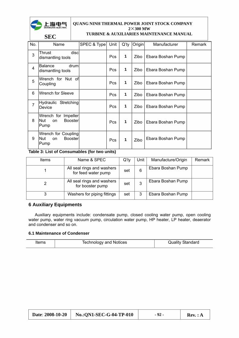
SEC
QUANG NINH THERMAL POWER JOINT STOCK COMPANY 2×300 MW
TURBINE & AUXILIARIES MAINTENANCE MANUAL
Date: 2008-10-20 No.:QN1-SEC-G-04-TP-010 - 92 - Rev. : A
No. Name SPEC & Type Unit Q’ty Origin Manufacturer Remark
3 Thrust disc dismantling tools Pcs 1 Zibo Ebara Boshan Pump
4 Balance drum dismantling tools Pcs 1 Zibo Ebara Boshan Pump
5 Wrench for Nut of Coupling Pcs 1 Zibo Ebara Boshan Pump
6 Wrench for Sleeve Pcs 1 Zibo Ebara Boshan Pump
7 Hydraulic Stretching Device Pcs 1 Zibo Ebara Boshan Pump
8 Wrench for Impeller Nut on Booster Pump
Pcs 1 Zibo Ebara Boshan Pump
9 Wrench for Coupling Nut on Booster Pump
Pcs 1 Zibo Ebara Boshan Pump
Table 3: List of Consumables (for two units)
Items Name & SPEC Q’ty Unit Manufacture/Origin Remark
1 All seal rings and washers for feed water pump set 6 Ebara Boshan Pump
2 All seal rings and washers for booster pump set 3 Ebara Boshan Pump
3 Washers for piping fittings set 3 Ebara Boshan Pump
6 Auxiliary Equipments
Auxiliary equipments include: condensate pump, closed cooling water pump, open cooling water pump, water ring vacuum pump, circulation water pump, HP heater, LP heater, deaerator and condenser and so on.
6.1 Maintenance of Condenser
Items Technology and Notices Quality Standard
SEC
QUANG NINH THERMAL POWER JOINT STOCK COMPANY 2×300 MW
TURBINE & AUXILIARIES MAINTENANCE MANUAL
Date: 2008-10-20 No.:QN1-SEC-G-04-TP-010 - 93 - Rev. : A
I. Cleaning and Water Filling for Leakage Detection
1. Clean titanium tube:
(1) Dismantle condenser cover;
(2) Completely flush and clean equipments with water up to pressure 30MPa, or clean by plastic bullets.
(3) Dry titanium tube and tube plate by blowing compressed air.
(4) Implete acid cleaning if scalling on titanium tube can not be completely cleaned by HP water, but specific technology measures must be prepared beforehand.
2. Clean sundries in water chamber, and remove the rust on inner wall of water chamber, condenser cover and tube plate, and apply two coatings of antirust paint on inner wall of water chamber and cover, and apply epoxy resin on tube plate.
3. Fill water on steam side of condenser for leakage detection:
(1) Place one piece of spiral jack specially made on spring seat of each condenser.
(2) Open make-up water valve, add demineralized water at steam side; fill water up to level of shaft seal in casing if high-level water filling to be adopted; and fill water to manhole door at steam side if low-level to be adopted.
(3) Check and leakge at titanium tube and expansion opening as adding water.
(4) Apply special plugs at both ends of titanium tube in case any tube leakage is found, and apply tube expander in case of leakage at expansion opening.
(5) Check any leakage points on throat of condenser, corrugated crossover pipe and evacuum system, mark them, and implement repair welding after discharging water.
(6) After discharging water, open manhole door and check any cracks on weld crater of steam side of condenser, if any, grind the position with cracks and repair by welding.
Notice: Before filling water on steam side of condenser, check and confirm appropriate support of jack under spring seat, and quickly implement high-level water filling for leakage detection.
4. Clean rubber ball net.
1. Plane of manhole door shall be flat without crossing groove trace or corrosion, rubber washer being integral without aging.
2. Inner wall of tube plate, water chamber and titanium tube shall be cleaned without mud dirty, no garbage, grease stain and sundries on steam side, titanum tube being without serious corrosion, crack and dent.
3. No seepage on titanium tube and expansion opening.
4. Equipments, tubes and welds in vacuum system shall be without sand inclusion, blowing corrosion and leakage.
5. Piping, flange and gland seams in condensate water system shall be without sand inclusion, blowing corrosion and leakage.
6. After applying epoxy resin on tube plate`, scrape the opening of tube to avoid blocking of rubber ball.
SEC
QUANG NINH THERMAL POWER JOINT STOCK COMPANY 2×300 MW
TURBINE & AUXILIARIES MAINTENANCE MANUAL
Date: 2008-10-20 No.:QN1-SEC-G-04-TP-010 - 94 - Rev. : A
II. Filling Compressed Air to Detect
Leakage
Filling compressed air in condenser for leakage detection (exclude in common-maitenance project):
(1) Ater high-level water filling in condenser, close various valves on drain piping going to condenser;
(2) Change one vacuum gauge on condenser to be 1.5 level pressure gauge, close primary valves of the rest vacuum gausges.
(3) Open valve on condenser for filling compressed air, closely monitor the pressure inside condenser not exceeding 0.04MPa (contact by use of walkie-talkie).
(4) After pressure rising in condenser, check air tightness of the part over level of water filling; pay spaicla attention to inspection of LP casing, cross over pipe and anti-explosion doo`r.
(5) Stop filling compressed air, discharge water at steam side of condenser.
Strictly control pressure to be under 0.05MPa, so as to avoid deformation of condenser.
III. Checking and
Cleaning of Steam Side
1. Open manhole door on steam side, check corrosion of throat and outer scalling of titanum tube, and clean the salt scale.
2. Check corrosion state of titanium tube caused by steam flushing, ensure the tube is without damages such as deformation.
3. Check fasteness of titanium tube on intermedate partition, no loosening.
4. Check smoothness of spraying hole on condensate re-circulation pipe, demineralized make-up water pipe, desuperheating water pipe and so on.
5. Check intactness of water and steam damper and clean internal sundries.
6. Check intactness of rubber washer of manhole door, fasteness of joint adhesive, and appropriate closess for air tightenss.
IV.
Maintenance of Hot well, Water Level, Valve
1. Cleaning and Inspection of Hotwell:
(1) Remove screw, open manhole door, and clean internal sundries.
(2) Check hotwell inner rust and corrosion, and remove the thick and apply anti-corrosion paint.
(3) Check vacuum deoxidation devices for intactness of components, including spray
SEC
QUANG NINH THERMAL POWER JOINT STOCK COMPANY 2×300 MW
TURBINE & AUXILIARIES MAINTENANCE MANUAL
Date: 2008-10-20 No.:QN1-SEC-G-04-TP-010 - 95 - Rev. : A
plate and support..
(4) After inspection, put in washer and restore manhole door.
2. Check water level.
3. Dismantle and inspect various valves of condensate water recirculation system.
V. Restoration
1. Close condenser cover: clean bolts on bid end cover, put rubber strip into flange groove of condenser and make the joint 45° by pressing. Lift big end cover up by crane and place it in position. Apply white lead oil on flange bolt and head of through bolts and fasten the nuts, and install the lower cover.
2. Loose jack on spring seat of condenser.
3. Check support spring.
6.2 Maintenance of Condensate Water Pump
Items Technology and Notices Quality Standard
I. Dismantling
1.Shut off power supply of condensate pump, hang signs, and remove electric wire; remove connection bolt between electric motor and pump body as well as connection bolt of coupling, record original center data and lift out motor and place it on the sleeper previously arranged.
2. Dismantle various instrumentation connection piping, seal water and cooling water connection piping, remove flange bolts on inlet and outer water piping of condensate pump.
3. Measure horizontalness of motor and make detailed record.
4. Remove connection bolts between pump seat and outer cylinder, lift up pump body in vertical and place on assembling frame of similar height; or place in horizontal with pump outlet flange of one end placed downward on wooden plate and with the other end placed on leveled sleeper. Shaft head at driving end shall be leveled also.
5. Dismantle coupling, thrust ring of bearing cover and various bearing one by one.
6. Dismantle cooling coil, seal oil cylinder, thrust pad, etc. one by one, and then disassemble thrust bearing seat.
7.Dismantle floating ring seal gland, return water
SEC
QUANG NINH THERMAL POWER JOINT STOCK COMPANY 2×300 MW
TURBINE & AUXILIARIES MAINTENANCE MANUAL
Date: 2008-10-20 No.:QN1-SEC-G-04-TP-010 - 96 - Rev. : A
pipe and sleeve one by one, and integrally remove the seal parts for independent separation.
8. Draw out throttle sleeve by three (3) M10 long bolts.
9. Dismantle one by one the impeller locking nut, inducer, adjusting sleeve, inlet trumpet, inducer chamber and primary impeller and key
l0. After dismantling seal water filling piping, remove housing of guide vane, impeller location, shaft sleeve, taper sleeve, secondary impeller key, etc. one by one, and mark on these dismantled parts. During dismantling, rotor and stator shall be provided with wooden spacer below, and maintain in relevant level to prevent bumping and rubbing of components.
11. Dismantle reducing housing and straight pipe section I & II, intermediate bearing seat and guide bearing.
12. Loose sleeve coupling.
13. Lift carefully the main shaft and lower shaft to V-shape wood pad.
II. Cleaning and Checking
1. Clean and check main shaft;
(1) Implement NDT test after cleaning main shaft.
(2) Measure shaking of main shaft; place shaft on special tools, apply lubrication oil on journal when cleaning, put contact of dial gauge in various measuring positions, slowly turn around main shaft for one circle, and the difference of readings on dial gauge is namely the value of shaking.
2.Clean and check impeller.
(1) Polish impeller by sand paper.
(2) Check matching of impeller groove and key;
(3) Check and measure clearance between inner impeller hole and shaft.
(4) Check and measure the radial clearance between outer impeller edge and seal ring.
3.Clean and check guide shell:
(1)Polish contact face and flow channel on guide shell by sand paper.
(2)Check clearance between guide shell and seal ring and guide bearing;
4.Clean and check bearing sleeve, guide bearing
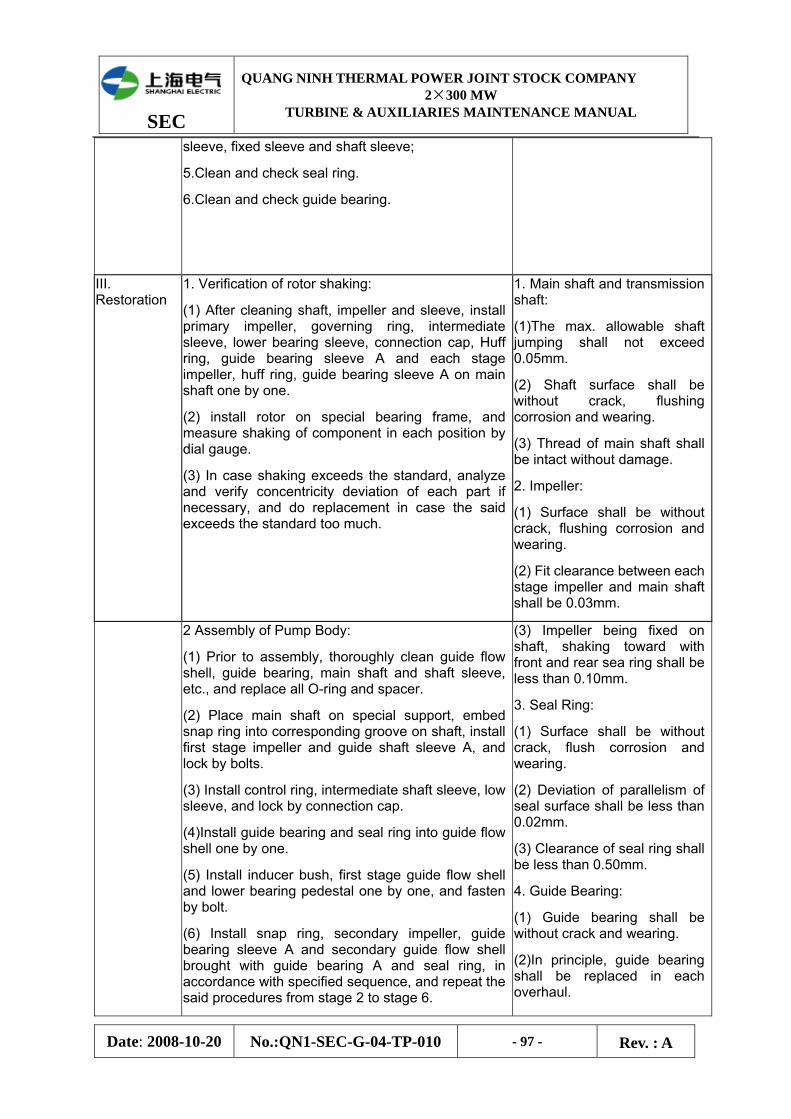
SEC
QUANG NINH THERMAL POWER JOINT STOCK COMPANY 2×300 MW
TURBINE & AUXILIARIES MAINTENANCE MANUAL
Date: 2008-10-20 No.:QN1-SEC-G-04-TP-010 - 97 - Rev. : A
sleeve, fixed sleeve and shaft sleeve;
5.Clean and check seal ring.
6.Clean and check guide bearing.
III. Restoration
1. Verification of rotor shaking:
(1) After cleaning shaft, impeller and sleeve, install primary impeller, governing ring, intermediate sleeve, lower bearing sleeve, connection cap, Huff ring, guide bearing sleeve A and each stage impeller, huff ring, guide bearing sleeve A on main shaft one by one.
(2) install rotor on special bearing frame, and measure shaking of component in each position by dial gauge.
(3) In case shaking exceeds the standard, analyze and verify concentricity deviation of each part if necessary, and do replacement in case the said exceeds the standard too much.
1. Main shaft and transmission shaft:
(1)The max. allowable shaft jumping shall not exceed 0.05mm.
(2) Shaft surface shall be without crack, flushing corrosion and wearing.
(3) Thread of main shaft shall be intact without damage.
2. Impeller:
(1) Surface shall be without crack, flushing corrosion and wearing.
(2) Fit clearance between each stage impeller and main shaft shall be 0.03mm.
2 Assembly of Pump Body:
(1) Prior to assembly, thoroughly clean guide flow shell, guide bearing, main shaft and shaft sleeve, etc., and replace all O-ring and spacer.
(2) Place main shaft on special support, embed snap ring into corresponding groove on shaft, install first stage impeller and guide shaft sleeve A, and lock by bolts.
(3) Install control ring, intermediate shaft sleeve, low sleeve, and lock by connection cap.
(4)Install guide bearing and seal ring into guide flow shell one by one.
(5) Install inducer bush, first stage guide flow shell and lower bearing pedestal one by one, and fasten by bolt.
(6) Install snap ring, secondary impeller, guide bearing sleeve A and secondary guide flow shell brought with guide bearing A and seal ring, in accordance with specified sequence, and repeat the said procedures from stage 2 to stage 6.
(3) Impeller being fixed on shaft, shaking toward with front and rear sea ring shall be less than 0.10mm.
3. Seal Ring:
(1) Surface shall be without crack, flush corrosion and wearing.
(2) Deviation of parallelism of seal surface shall be less than 0.02mm.
(3) Clearance of seal ring shall be less than 0.50mm.
4. Guide Bearing:
(1) Guide bearing shall be without crack and wearing.
(2)In principle, guide bearing shall be replaced in each overhaul.

SEC
QUANG NINH THERMAL POWER JOINT STOCK COMPANY 2×300 MW
TURBINE & AUXILIARIES MAINTENANCE MANUAL
Date: 2008-10-20 No.:QN1-SEC-G-04-TP-010 - 98 - Rev. : A
(7) Install clip bush A and fixed sleeve A, to connect main shaft and transmission shaft.
(8) After installing shaft sleeve A and B into transmission shaft, lock by bolts.
(9)Fix reducing pipe and secondary guide flow shell.
(10) Cover bearing pedestal sleeve, bringing with guide bearing A, on transmission shaft.
(11) Cover pump seat sleeve, fixed with guide bearing I, on transmission shaft well and fix with connection bolt.
(12) Cover two (2) O-ring on lower bearing gland sleeve, and fix with bearing pedestal by bolt, then install float ring seal device, motor frame and thrust bearing pedestal, etc. inside.
(13) Lift pump body into cylinder, fasten bolts, and then use gradienter to measure the upper plane level of motor frame, being less than 0.05mm, and measure total displacement of rotor and lock the nut after the said displacement satisfying requirement.
(14) Lift motor on pump support, measure clearance between two couplings, and deviation of center and plane, connect coupling bolts after adjusting the said to the standard.
Remove bearing sleeve, guide bearing sleeve A, shaft sleeve A, fixed sleeve A and shaft sleeve B:
(1) Outer surface being smooth without wearing.
(2) Fit clearance between bearing inner hole and main shaft shall be less than 0.03mm.
(3) Fit clearance between bearing sleeve and guide bearing shall be not greater than 0.15mm.
6, Guide Flow Shell:
(1) Seal surface being bright and clean, flat and without crack and wearing.
(2) Flow path being smooth without burr.
(3)Surface roughness shall not exceed Ra0.8um.
7. Coupling:
(])Coupling components being intact and surface without cracks.
(2)Unevenness of coupling adjusting washer shall be less than 0.03mm.
Surface roughness shall not exceed RaO.8um
(3) Deviation of centers of water pump and motor shaft shall be less than 0.05mm, and plane deviation be less than 0.05mm.
8. Level of plane on motor frame shall be less than 0.05mm.
6.3 Maintenance of Closed and Open Cooling Water Pump
Items Technology and Notices Quality Standard
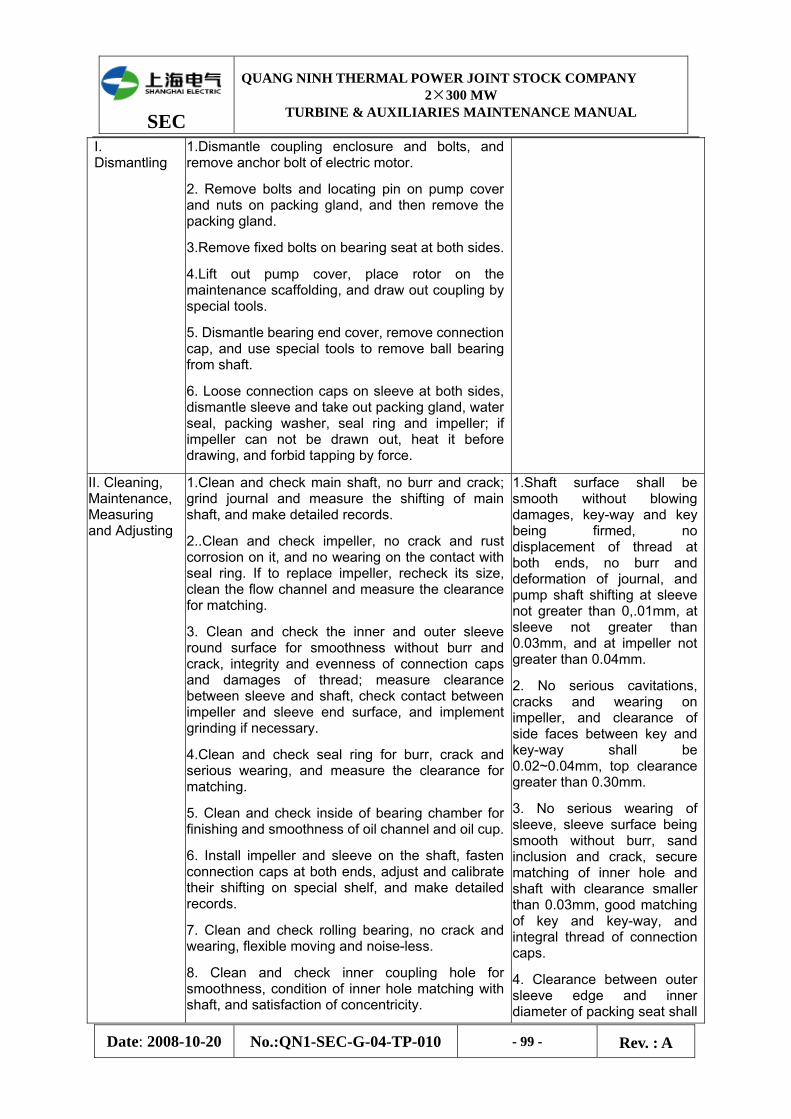
SEC
QUANG NINH THERMAL POWER JOINT STOCK COMPANY 2×300 MW
TURBINE & AUXILIARIES MAINTENANCE MANUAL
Date: 2008-10-20 No.:QN1-SEC-G-04-TP-010 - 99 - Rev. : A
I. Dismantling
1.Dismantle coupling enclosure and bolts, and remove anchor bolt of electric motor.
2. Remove bolts and locating pin on pump cover and nuts on packing gland, and then remove the packing gland.
3.Remove fixed bolts on bearing seat at both sides.
4.Lift out pump cover, place rotor on the maintenance scaffolding, and draw out coupling by special tools.
5. Dismantle bearing end cover, remove connection cap, and use special tools to remove ball bearing from shaft.
6. Loose connection caps on sleeve at both sides, dismantle sleeve and take out packing gland, water seal, packing washer, seal ring and impeller; if impeller can not be drawn out, heat it before drawing, and forbid tapping by force.
II. Cleaning, Maintenance, Measuring and Adjusting
1.Clean and check main shaft, no burr and crack; grind journal and measure the shifting of main shaft, and make detailed records.
2..Clean and check impeller, no crack and rust corrosion on it, and no wearing on the contact with seal ring. If to replace impeller, recheck its size, clean the flow channel and measure the clearance for matching.
3. Clean and check the inner and outer sleeve round surface for smoothness without burr and crack, integrity and evenness of connection caps and damages of thread; measure clearance between sleeve and shaft, check contact between impeller and sleeve end surface, and implement grinding if necessary.
4.Clean and check seal ring for burr, crack and serious wearing, and measure the clearance for matching.
5. Clean and check inside of bearing chamber for finishing and smoothness of oil channel and oil cup.
6. Install impeller and sleeve on the shaft, fasten connection caps at both ends, adjust and calibrate their shifting on special shelf, and make detailed records.
7. Clean and check rolling bearing, no crack and wearing, flexible moving and noise-less.
8. Clean and check inner coupling hole for smoothness, condition of inner hole matching with shaft, and satisfaction of concentricity.
1.Shaft surface shall be smooth without blowing damages, key-way and key being firmed, no displacement of thread at both ends, no burr and deformation of journal, and pump shaft shifting at sleeve not greater than 0,.01mm, at sleeve not greater than 0.03mm, and at impeller not greater than 0.04mm.
2. No serious cavitations, cracks and wearing on impeller, and clearance of side faces between key and key-way shall be 0.02~0.04mm, top clearance greater than 0.30mm.
3. No serious wearing of sleeve, sleeve surface being smooth without burr, sand inclusion and crack, secure matching of inner hole and shaft with clearance smaller than 0.03mm, good matching of key and key-way, and integral thread of connection caps.
4. Clearance between outer sleeve edge and inner diameter of packing seat shall

SEC
QUANG NINH THERMAL POWER JOINT STOCK COMPANY 2×300 MW
TURBINE & AUXILIARIES MAINTENANCE MANUAL
Date: 2008-10-20 No.:QN1-SEC-G-04-TP-010 - 100 - Rev. : A
be 0.5~-0.8mm.
5. Diametric clearance between seal ring and impeller shall be 0.5~0.8mm.
6. Tightening force for matching of inner bearing hole and shaft shall be 0~0.02mm, and equivalent for outer circle with bearing chamber shall be 0~0.02mm, and axial clearance between bearing at free end and packing gland shall be 0~0.10mm.
8. Standard of rotor bending:
At journal: not greater than 0.02mm.
At sleeve: not greater than 0.05mm;
At seal ring of impeller: not greater than 0.08mm.
9. Inner hole of coupling shall be smooth without burr, and tightening force with shaft shall be 0~0.03mm.
10. Pump body and cover shall be without crack and blister, bonding surfaces being smooth and even, no burr and rust.
11. Locating pin on pump cover shall be integral without bending, and thread being complete and smooth.
12. Coupling center: deviation of circumference and plane shall not be greater than 0.05mm. distance between two couplings shall be 4~6mm.
13. After assembly, turning of rotor shall be flexible without non-smoothness.
III. Restoration
1. Place rotor finishing shifting calibration on the shelf, and install seal ring, packing washer, water seal , packing gland, water retaining ring and inner bearing end cover on shaft one by one; heat rolling
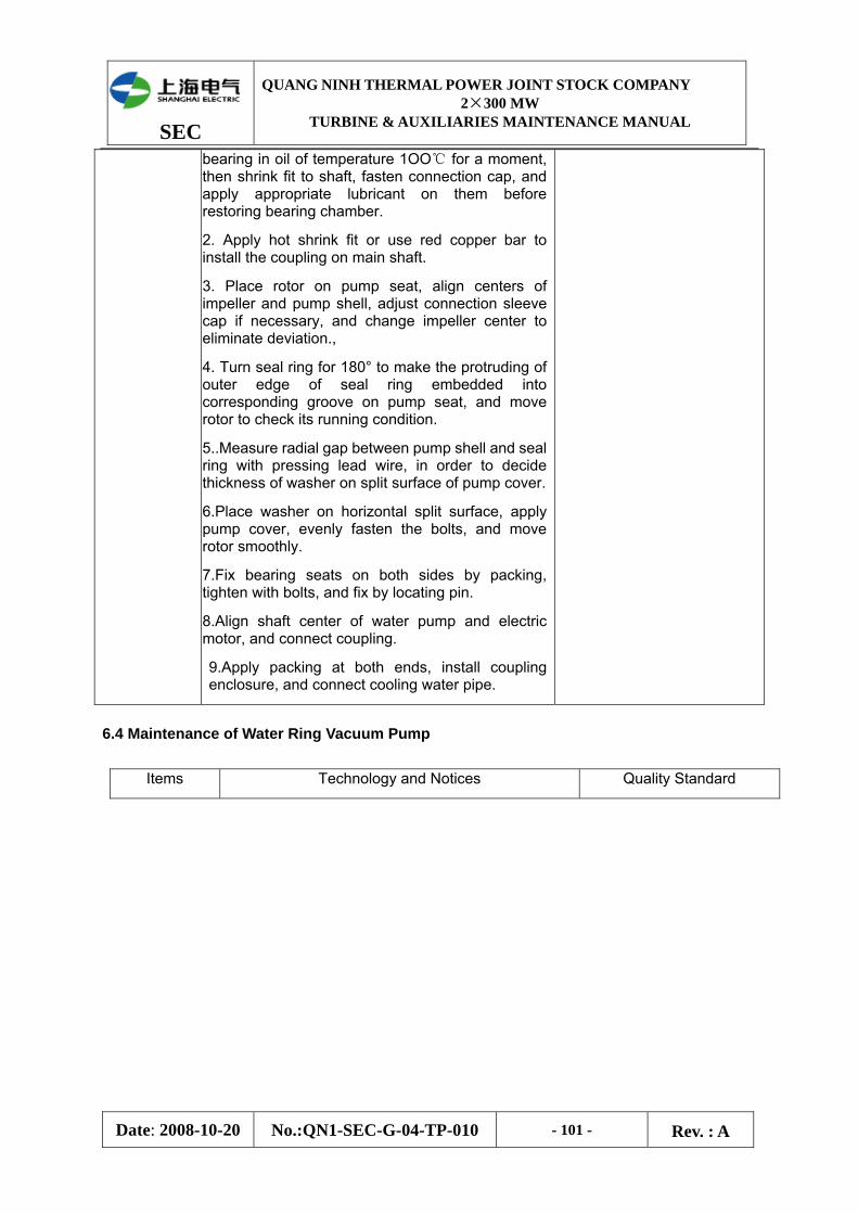
SEC
QUANG NINH THERMAL POWER JOINT STOCK COMPANY 2×300 MW
TURBINE & AUXILIARIES MAINTENANCE MANUAL
Date: 2008-10-20 No.:QN1-SEC-G-04-TP-010 - 101 - Rev. : A
bearing in oil of temperature 1OO℃ for a moment, then shrink fit to shaft, fasten connection cap, and apply appropriate lubricant on them before restoring bearing chamber.
2. Apply hot shrink fit or use red copper bar to install the coupling on main shaft.
3. Place rotor on pump seat, align centers of impeller and pump shell, adjust connection sleeve cap if necessary, and change impeller center to eliminate deviation.,
4. Turn seal ring for 180° to make the protruding of outer edge of seal ring embedded into corresponding groove on pump seat, and move rotor to check its running condition.
5..Measure radial gap between pump shell and seal ring with pressing lead wire, in order to decide thickness of washer on split surface of pump cover.
6.Place washer on horizontal split surface, apply pump cover, evenly fasten the bolts, and move rotor smoothly.
7.Fix bearing seats on both sides by packing, tighten with bolts, and fix by locating pin.
8.Align shaft center of water pump and electric motor, and connect coupling.
9.Apply packing at both ends, install coupling enclosure, and connect cooling water pipe.
6.4 Maintenance of Water Ring Vacuum Pump
Items Technology and Notices Quality Standard
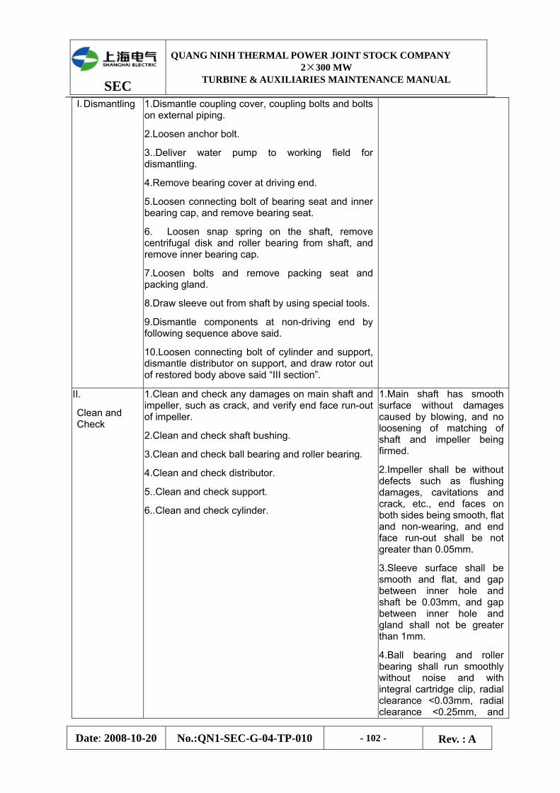
SEC
QUANG NINH THERMAL POWER JOINT STOCK COMPANY 2×300 MW
TURBINE & AUXILIARIES MAINTENANCE MANUAL
Date: 2008-10-20 No.:QN1-SEC-G-04-TP-010 - 102 - Rev. : A
I. Dismantling
1.Dismantle coupling cover, coupling bolts and bolts on external piping.
2.Loosen anchor bolt.
3..Deliver water pump to working field for dismantling.
4.Remove bearing cover at driving end.
5.Loosen connecting bolt of bearing seat and inner bearing cap, and remove bearing seat.
6. Loosen snap spring on the shaft, remove centrifugal disk and roller bearing from shaft, and remove inner bearing cap.
7.Loosen bolts and remove packing seat and packing gland.
8.Draw sleeve out from shaft by using special tools.
9.Dismantle components at non-driving end by following sequence above said.
10.Loosen connecting bolt of cylinder and support, dismantle distributor on support, and draw rotor out of restored body above said “III section”.
II.
Clean and Check
1.Clean and check any damages on main shaft and impeller, such as crack, and verify end face run-out of impeller.
2.Clean and check shaft bushing.
3.Clean and check ball bearing and roller bearing.
4.Clean and check distributor.
5..Clean and check support.
6..Clean and check cylinder.
1.Main shaft has smooth surface without damages caused by blowing, and no loosening of matching of shaft and impeller being firmed.
2.Impeller shall be without defects such as flushing damages, cavitations and crack, etc., end faces on both sides being smooth, flat and non-wearing, and end face run-out shall be not greater than 0.05mm.
3.Sleeve surface shall be smooth and flat, and gap between inner hole and shaft be 0.03mm, and gap between inner hole and gland shall not be greater than 1mm.
4.Ball bearing and roller bearing shall run smoothly without noise and with integral cartridge clip, radial clearance <0.03mm, radial clearance <0.25mm, and

SEC
QUANG NINH THERMAL POWER JOINT STOCK COMPANY 2×300 MW
TURBINE & AUXILIARIES MAINTENANCE MANUAL
Date: 2008-10-20 No.:QN1-SEC-G-04-TP-010 - 103 - Rev. : A
clearance between bearing and shaft shall be ±0.01mm.
5.Distributor surface shall be smooth and flat without wearing, and non-parallelism on both sides shall not be less than 0.05mm.
6..No defects in support inner chamber, such as flushing trace and crack. Upper and lower flange being non-wearing, and non-parallelism being not less than 0.05mm.
7.No wearing on contact of both cylinder ends, and non-parallelism being not less than 0.10mm.
III.
Restoration
l.Flatly place the support of non-driving end on the board, and apply seal gel on the contact surface with distributor.
2.Flatly place the distributor in corresponding position of the support, and place cylinder in corresponding position of distributor applied with seal gel.
3..Make rotor’s non-driving end upside down, put cylinder in, and measure the distance from cylinder end face to rotor end face, error of integral circle not greater than 0.20mm.
4..Apply seal gel on distributor and support at driving end, place them on cylinder one by one, and then fix bolts on both walls, transversely place pump on the deck, and level four feet of support.
5.Cover shaft sleeve on main shaft.
6..Install packing set, water seal ring and packing gland one by one.
7.. Cover main shaft with inner bearing sleeve.
8.. Measure total thickness of roller bearing, centrifugal disk and snap spring at driving end, and measure the length of snap spring groove on shaft and of bearing shoulder, and adjust the said by grinding end face of centrifugal disk or adding sheet copper, if any difference, until the difference down to zero.
9...Measure ball bearing, roller bearing, centrifugal disk and snap spring at non-driving end, and
1. Fixed bolts on cylinder shall not be fastened too much for leveling of support base leveling purpose, for a period of 24h, and then fasten all such fixed bolts.
2. 0.15 一O.25mm.Clearance between water seal ring and packing chamber shall be 0.15-0.25mm, and that between packing press ring and packing chamber shall be 0.20~0.30mm.
0.20~O.30mm.
3.Clearance between ball bearing and inner bearing wall shall be 0.20mm when adjusting in accordance with technology as stated in clause 9.10.
4.Total displacement of rotor shall be 0.60-1.00mm. Move rotor as measuring, once at interval 90’, four(04) times in total, and take the minimum of such four value.
5.Requirement of coupling center: both deviation of
SEC
QUANG NINH THERMAL POWER JOINT STOCK COMPANY 2×300 MW
TURBINE & AUXILIARIES MAINTENANCE MANUAL
Date: 2008-10-20 No.:QN1-SEC-G-04-TP-010 - 104 - Rev. : A
measure the length of snap spring groove on shaft and of bearing shoulder, and adjust the said by grinding end face of centrifugal disk or adding sheet copper if any difference.
10..Measure thickness of ball bearing and roller bearing at non-driving end, measure thickness of inner bearing cap and bearing seat, and measure depth of shoulder blade between inner bearing cap and bearing seat, to adjust spring hold-down force.
11. Install roller bearing, centrifugal disk and snap spring at driving end, and fix inner bearing cap with bearing seat which is fixed already, and cover with bearing end cover which will be fixed with bearing seat on support.
.
12.Place 12 pieces of small spring into locating hole for inner bearing cap at non-driving end, and install ball bearing, roller bearing, centrifugal disk and snap spring on shaft one by one, mount bearing seat and fix it with inner bearing cap.
13. Apply dial gauge at driving end, measure total displacement of rotor after its several run-off through adjusting fixed bolt and stud bolt; then place rotor in the position of cylinder, and measure the gap between bearing seat and end surface of support, and fabricate washer in accordance with such gap.
14.Install bearing end cover and fix it with bearing seat on support.
15.Cover rotor with coupling.
16..Place packing on packing sleeve.
17.Locate water pump and align center of coupling.
18..Conner external piping.
plane and of circumference shall not be greater than 0.05mm.
6.5 Maintenance of Circulating Pump
(1)Maintenance of Electric Motor and Upper & Lower Frame
item Process methods and attention matter Quality standard
I) Electric motor
I. Notify the staff of hot working and electric maintenance that all of the thread end (including: upper & lower guide shoe and thrust tile, seal protection with water pressure etc.) influencing the suspend of motor shall be removed, and lubricate the upper & lower frame.
2. The process of disassembly for electric motor:
The surface of bushing bearing shall be smooth without burr.

SEC
QUANG NINH THERMAL POWER JOINT STOCK COMPANY 2×300 MW
TURBINE & AUXILIARIES MAINTENANCE MANUAL
Date: 2008-10-20 No.:QN1-SEC-G-04-TP-010 - 105 - Rev. : A
(1)The process of disassembly for upper frame:Remove the coupling screw between adjustable framework seat and upper frame, and then unfix the pin in order to suspend the adjustable framework seat onto the space for maintenance.
(2) Loosen off the 4 pieces of pressing plate and then loose the set bolt so as to extract 4 pieces of guide shoe; before that, the three steps shall be done including: firstly measurement the gap between guide shoes, secondly keeping a record and last removing the upper support for guide shoe.
(3) Remove the connecting flange between upper frame and oil cooler, and then suspend the oil cooler to maintenance site. It shall be cautioned not to destroy the hot working wiring of thrust tile when doing it.
(4)Jack up the electric rotor by using 4 jack with 5t and take off the clasp so as to heat up and suspend the thrust head to the maintenance site, at the same time, above actions shall meet the requirements including: height of jack up 5~8mm,uniformly heat up for thrust head under the temperature between 150~200℃,the thrust head shall be pack up by asbestos cloth to uniformly cool down when suspended to maintenance site.
(5) The process of disassembly for lower frame:firstly, loosen off the fastening bolt and then take off the guide bearing cover; secondly, loosen off the whole plate bolt and then take off the cover plate; then remove and lay down slowly the bottom ring connecting bolt, lower cover of guide bearing (including oil cooler) and connecting bolt of lower frame, lastly set backrest wheel of pump shaft onto the suspending plate of pump by crossing the electric machine. It shall be cautioned that avoid any person suffer compression injury when lay down the lower cover of guide bearing.
(6) Remove the pressing plate and set bolt for guide bearing to lift down the 4 pieces of guide bearing; and then, disassembly the bearing plate and coupling bolt for lower guide bearing to take off the 4 pieces of bearing plate.
(7) Disassembly the coupling bolt between upper frame and electric machine, and then suspend the upper frame to the clear space, finally removes the dust hood.
(8) Disassembly the motor rotor and stator by electric maintenance staff.
SEC
QUANG NINH THERMAL POWER JOINT STOCK COMPANY 2×300 MW
TURBINE & AUXILIARIES MAINTENANCE MANUAL
Date: 2008-10-20 No.:QN1-SEC-G-04-TP-010 - 106 - Rev. : A
II)Checking, cleaning and measurement
1.Guide shoe: coat equably the red lead powder on the guide shoe shelves of thrust head whose surface shall be inspected by moving the guide shoe adhered on it to repair and scrape the unconformity surface. It shall be guaranteed that the insulated liner shall be not worn out and the guide shoe meet the requirement of insulation test.
2 Thrust tile: coat equably the red lead powder on the flat plate which shall be inspected by moving the stressed surface set on the plat plate to repair and scrape for the unconformity surface. It shall be guaranteed that the stress surface metal is no defects such as crack, shelling, wearing, pore and flute etc.
3. Thrust head: remove the coupling bolt of mirror plate, and then check whether there is any defect such as wearing, pore and hard spot etc. After the two steps completed including cleaning the insulating plate and assembling the thrust head, the insulation test shall be carried out to measure the surface wow flutter for thrust head.
4. Oil cooler: it shall be required that the hydraulic pressure of pump in the upper & lower oil cooler shall be more than 35N and keep it for half an hour in pressure test. The waste in the connecting chamber of cotitanium tube shall be clear up to ensure the tube through and free
5 Checking of bearing chamber: clean the chamber by the clean cloth to ensure the oil level indicator clarity and the chamber no leakage, oil dirt, corrosion spot and burr;
6. Replace all the seal ring and O-ring.
7. Check and clean the coupling and its bolt: ensure the coupling bolt hole undamaged, without deformation and crack; and the coupling bolt thread undamaged, without bending and wearing, the fitting between the bolt and hole shall not be loosened.
1. The contact surface area of guide shoe shall be more than 75% of all area and 2-3 points in each cm2 area
2. The mirror plate area of thrust tile and thrust head shall be more than 75% of all area and 2-3 points in each cm2 area
3. The distribution of thrust head and rotor axis shall be 0.01 ~ 0.03mm and the surface wow flutter of thrust head shall be less than 0.02mm.
III)Assembly 1. Firstly put the lower cover of bearing chamber of lower frame(including oil cooler) onto the suspend plate under the pump coupling, and then suspend the electric machine seat onto the pump cover, lastly put in the pin and fasten screw.
2.Assembly the motor stator and rotor by electric maintenance staff.
3. Firstly, fit the upper frame and measure its horizon deviation, and then fasten the connection screw; secondly, wipe the lubricating oil and grease on the thrust tile to mount it; then, heat the thrust
the horizon deviation of upper frame <0.02mm/m
The rotor shall be located in

SEC
QUANG NINH THERMAL POWER JOINT STOCK COMPANY 2×300 MW
TURBINE & AUXILIARIES MAINTENANCE MANUAL
Date: 2008-10-20 No.:QN1-SEC-G-04-TP-010 - 107 - Rev. : A
head and then pass through the rotor to fix the pad; lastly put down the jack
4. Adjustment of the magnetic field centre and: if after adjust of the thrust head horizon the requirement would not be met, the thrust tile axial displacement shall be adjusted up and down by using the adjustment bolt under the thrust tile to ensure the contact equably between every thrust tile and mirror plate of thrust head. Then, the adjustment holt shall be fastened with locking plate, and the set screw both sides of thrust tile shall be set in working position(in the middle of the stop groove both sides of thrust tile) and be tightened with flat nut.
5. Cooperate with the electric maintenance staff and adjust the air gap: mount the bearing bracket of upper frame and set up the upper guide shoe, and push the electric drive rotor by the radial displacement of upper guide shoe, then adjust the air gap so as to ensure the rotor in the middle of the stator radial direction
6. Correction of the wow flutter for electric drive rotor:
(1) The Vaseline shall be applied for the 4 pieces of upper guide tile, and then gently screw up the adjustable screw to radial clearance nearly between the guide shoe and thrust tile, but keep it in the condition of still being moved
(2) The thrust head and backrest wheel of electric drive rotor shall be severally divided into 8 parts in the circle direction, and the bisectrix shall be consistent of both up and down; and then, two of cent meters (in the same direction) shall be respectively placed on the thrust head (at the guide bearing location) and the backrest wheel; lastly shaft turning gear(exclusive use) shall be mounted onto the electric driven rotor and slowly turn around by manpower(to be consistent with the pump turning direction) so as to read out the meter count of 8 point of division.
(3) The net flutter value of electric drive rotor shall be calculated through following method: the whole flutter value (clearance of guide shoe) located at the guide bearing subtracted from the Max. (the full flutter value) of reading difference corresponding the 8 point on the cent meter located at the coupling backrest wheel gives the net flutter value. When the flutter valve exceed the permissible valve, thrust head shall be corrected as (adjust the medium insulation).The jigger shall recheck the
the centre of stator axial direction with the horizon deviation of thrust head ≤0.02mm/m.
The wow flutter ≤O.O5mm.
The Clearance in radius between the guide shoe and electric rotor axis shall be between 0.08~0.10mm; and the axial clearance between pressing plate and guide shoe be 0.50mm. After the assembly of the upper & lower oil cooler, the hydraulic test (hydraulic pressure working) shall be carried out and forbid the leakage in connecting flange and joint of cooling water.

SEC
QUANG NINH THERMAL POWER JOINT STOCK COMPANY 2×300 MW
TURBINE & AUXILIARIES MAINTENANCE MANUAL
Date: 2008-10-20 No.:QN1-SEC-G-04-TP-010 - 108 - Rev. : A
flutter degree until reach the requirement.
7.Assembly each component of bearing chamber for lower frame (prevent the junk from descending into the oil cavity )
(1) Fix the lower bearing plate onto the seat support of guide shoe and mount the 4 pieces of lower guide shoe (coated with Vaseline), then adjust its gap and tighten the adjustable screw and nut, lastly fit on the upper pressing plate.
(2) Fit on the lower end bracket(including the oil cooler) and bottom ring for lower frame, then screw up the bolt of combination surface; mount oil baffler and end bracket for lower frame top, then screw down the coupling bolt.
(3) Assembly each component in the bearing chamber for upper frame (prevent the junk from descending into the oil cavity ): mount the oil cooler, guide shoe bracket and upper guide shoe(coated with Vaseline) , adjust the guide shoe gap and tighten the adjustable screw and nut; fit on the upper pressing plate and adjust the gap between the plate and guide shoe; lastly assembly the adjust framework seat and fasten the coupling bolt.
Item Process methods and attention matter Quality standard
(I)Disassembly
1. For pump backrest wheel, firstly clean up its lower axis surface and then suspend it firmly to heat up, secondly put it down and take out the clasp, thirdly hoist to the clear space, where the backrest wheel shall be wrapped up with asbestos cloth to cool down slowly, then loosen off the gland nut of bearing seal and the connecting flange & bolt between bearing seal and pump, lastly take off the stiffing box and cut out its filler.
Attention: the pump body shall be put behind the steel I – beam and connected with 2 bar of steel I – beam(be # form) by using 2 of flat bar, take the safety measure to prevent the destructive accident such as pump turn down into well etc.
2. For thordon journal bearings, remove its fixing bolt and raise it by using supported screw, and then suspend it to the clear space; remove the fasten bolt of hoist plate and put 2 bars of long steel I – beam at the location of lifting hook of outlet, then hoist the pump body onto the steel I – beam ,lastly suspend to the maintenance site respectively after the hoist plate and fixing bolt of connecting tube and pin have
disassembly
SEC
QUANG NINH THERMAL POWER JOINT STOCK COMPANY 2×300 MW
TURBINE & AUXILIARIES MAINTENANCE MANUAL
Date: 2008-10-20 No.:QN1-SEC-G-04-TP-010 - 109 - Rev. : A
been removed.
3. Firstly hoist the pump body and then put the 2 bars of steel I – beam at the location of lifting hook of short connecting tube, at last put down the pump body. After that, for bend pipe, remove its fixing bolt and pin and suspend it to the maintenance site.
4. Cover the intermediate bearing bracket with wood block(for the convenience of maintenance), remove the fixing bolt of stainless steel sleeve and hoist the sleeve to the clear space. For pump shaft , disassembly its semicircle coupling、2 clasp and 2 pin and then suspend it to recline on the clear place and support the intermediate thordon journal bearings by using screw.
5 Firstly hoist the pump body ,and then put the steel I – beam at the location of 2 lifting hooks of lower connecting tube, remove the fixing bolt between lower connecting tube and intermediate bearing bracket, at last, which shall be hoist to the clear space.; Hoist the pump body ,and then put the steel I – beam at the location of lifting hooks of guide blade body, remove the fixing bolt and pin of lower connecting tube ,at last, suspend the lower connecting tube and stainless steel sleeve to the clear space.
6. Suspend the rest of pump body to clear space to remove the fixing bolt and pin between the guide blade body and outer ring of moving blade. for guide blade body , slowly hoist it to the clear space by overhead crane and turn it over in 180° to make the direction of assistant thordon journal bearings upward. Lastly take out the water seal by removing its clamping ring and then prop up the assistant bearing by support screw to hoist it to the clear space.
Attention: the rest of pump body shall be covered with the wood block to prevent the human and object from dropping into the well after it was hoisted to the clear space.
7. Hoist the lower pump shaft and slowly put it onto the rubber cushion, then remove the coupling bolt between backrest wheel and impeller and loosen off the gland nut of seal ring to hoist pump shaft vertically. For backrest wheel, under it symmetrically put the 2 bars of steel I-beam and heat it up. Then, put down the pump shaft again and remove the clasp so as to hoist the pump shaft to recline on the ground , lastly take off the seal ring gland and seal.
Attention: the backrest wheel shall be wrapped firmly by asbestos cloth to cool down equably after it
SEC
QUANG NINH THERMAL POWER JOINT STOCK COMPANY 2×300 MW
TURBINE & AUXILIARIES MAINTENANCE MANUAL
Date: 2008-10-20 No.:QN1-SEC-G-04-TP-010 - 110 - Rev. : A
was heated.
(II) Checking、measurement and cleaning
1. The measurement of fit clearance between the upper pump shaft and backrest wheel.
2 The measurement、checking and cleaning of bearing for new rubber.
3 Replacement of all the seal ring, water seal, filler and rubber bearing.
4 The checking and cleaning of upper & lower connecting tube, water exit elbow, guide blade body , intermediate bearing bracket., hoist plate and such like combination surface, as well as pin and bolt.
5 Exchange , checking、measurement and cleaning of shaft liner
6. Checking、measurement and cleaning of backrest wheel of impeller.
7. checking and cleaning of the stuffing box and its gland, semicircle coupling of lower pump shaft, pressing plate of seal ring and clasp for every shelves; Gap measurement between the stuffing box and its gland
8. Checking、measurement and cleaning of impeller:
(1) The airproof test of oil pressure shall be carried out for impeller.
(2) exchange the u-type seal rubber ring in impeller and all other O-ring.
(3) Connection screw of blade and Impeller hub shall be filled with epoxy resin in the process of assembly.
1.Fitting stressed force 0.01~0.03mm,the bolt fittingly slide in the hole without loose; the fitting between pin and keyway shall be suited.
2. the clearance between the bearing outer circle and inner circle of bearing mounting shall be between 0.00~0.02mm;
the fitting between the thordon journal bearing and pump shaft:
upper race O.50 ~
O.75mm;
middle race 0.50 ~
O .75mm;
lower race o.50~O.75mm.
3. The fitting stressed force between shaft liner and pump shaft shall be 0.15~0.25mm.
4. the fitting clearance between the impeller backrest wheel and the pump shaft shall be 0.01~0.03mm.
5. The clearance standard shall be 1~2mm.
6. The test oil pump shall be 35N, time 5min, and without leakage.
7. The stress surface of clasp and groovy on the shaft shall be good condition, as well as contact surface of clasp. The clearance gage of 0.30mm shall not plug in, the both planes of clasp be parallel, the thickness error be ≤0.02mm.
SEC
QUANG NINH THERMAL POWER JOINT STOCK COMPANY 2×300 MW
TURBINE & AUXILIARIES MAINTENANCE MANUAL
Date: 2008-10-20 No.:QN1-SEC-G-04-TP-010 - 111 - Rev. : A
(III)Assembly again
1. The guide blade body shall be assembled with lower race thordon journal bearings and water seal and clamping ring of water seal in turn,and then turn it over to make the bearing downward.
2. Firstly, for the lower pump shaft, its backrest wheel shall be horizontally put onto the 2 bars of short steel I–beam, and house it into the shaft liner( heated) to cool it down, then heat up the backrest wheel. Secondly, hoist the lower pump shaft vertically to fit on the seal ring of gland, and then reeve the backrest wheel of impeller and clasp to waiting for the natural cooling of the impeller coupling by hoist the pump shaft. To convenient for put in, the impeller coupling shall be heated up in order to make the diameter of coupling inner circle 0.03 一 0.05mm bigger than outer circle of pump shaft.
3. After the horizontal degree of impeller have been adjusted and the axial clearance between lower pump shaft and impeller been measured, the seal ring shall be put on the lower side of impeller coupling to slowly put it into the impeller and fasten the bolt when after the pump shaft vertically be hoisted. The impeller shall be applied with lubricating oil(32# machine oil) and then hoist in the outer ring of moving blade. Lastly, raise up the guide blade body by overhead crane to put in the lower pump shaft slowly, and then pair right with mark to install the pin and fasten the bolt.
4. Firstly, for guide blade body, hoist and then to put the steel I-beam onto the its lifting hook and last put it down. After that, hoist the lower connection tube to guide blade body with lower sleeve assembly, and hammer into the pin and fasten the bolt directed to the mark. Secondly, put down the pump body and then set 2 bars of steel I-beam at the lifting hook of lower connection tube, last hoist down the intermediate bearing bracket and intermediate short connection tube, and fasten the bolt; put down the pump body and then set 2 bars of steel I-beam at the lifting hook of intermediate connection tube, and the bearing support shall be covered by wood block and fixed the intermediate rubber bearing. Thirdly, hoist the upper pump shaft vertically and link up the upper and lower pump shaft by semicircle coupling so as to put the upper sleeve into the pump shaft as well as fasten the bolt between intermediate rubber bearing and sleeve. It is shall be paid attention to
The axial clearance between lower pump shaft bottom and impeller shall be 0.03~0.05mm.
SEC
QUANG NINH THERMAL POWER JOINT STOCK COMPANY 2×300 MW
TURBINE & AUXILIARIES MAINTENANCE MANUAL
Date: 2008-10-20 No.:QN1-SEC-G-04-TP-010 - 112 - Rev. : A
that pair correctly with the mark and avoid confusing the upper and lower key when link up the upper and lower pump shaft by semicircle coupling.
5. Firstly, put down the pump body and then set 2 bars of steel I-beam at the lifting hook of intermediate connection tube, and hoist down the waterexit elbow as well as hammer into the pin and fasten the bolt directed to the mark. Secondly, put down the pump body and then set 2 bars of steel I-beam at the lifting hook of waterexit elbow, and hoist the inner connection tube and hoisting plate to the waterexit elbow, as well as hammer into the pin and fasten the bolt directed to the mark II. Thirdly, hoist the pump body vertically and put down the hoisting plate directed to the mark along the stay bolt of guide rail, and then fasten the bolt and put down the upper race rubber bearing. Attention: don’t forget put the copper tray for the bolt when fasten the waterexit elbow.
6. After the coupling of upper pump shaft be heated and put on the pump shaft and clasp, the coupling shall be raised up by 2 jacks to make it nature cooling. The jack height shall not be too high around 2~3mm. And then the concentricity of upper race bearing, which namely that all the around gap shall be the half of diameter gap, shall be adjusted.
(IV)
Ending work
1. Measurement of the outer ring clearance between blade and moving blade.
2. Measurement of the clamping ring clearance between blade and impeller so as to educe the outer ring clearance between blade and moving blade after the water pump running.
4. After make sure that the work of water pump bottom have finished, the whole plate of manhole door shall be covered well to prepare feed-water, then feed.
5. Loosen off the oil jack of steel gate by high-pressure oil pump (exclusive use), and then pump water in well, lastly hoist the steel gate to keep in clear place.
Attention: the steel gate shall be hoisted after the water level be same as that of outer steel gate.
6. The 32# machine oil shall be add into upper and lower frame of electric motor until to the high oil level of oil pointer.
7. Overall checkup whether or not there be the leakage in the work item.
8. Sorting and cleaning of the pump and
The clearance standard of outer ring between blade and moving blade shall be 0.15~1.60mm, and the standard≤0.03mm.

SEC
QUANG NINH THERMAL POWER JOINT STOCK COMPANY 2×300 MW
TURBINE & AUXILIARIES MAINTENANCE MANUAL
Date: 2008-10-20 No.:QN1-SEC-G-04-TP-010 - 113 - Rev. : A
maintenance site.
Attention: after maintenance completed, the all of well、pit、hole and cavity that require opened for maintenance shall be closed and covered well.
9. Go through the terminal formality and make out the trial run document to test pump and measure its vibration.
(V)
The installation process for centre and its system auxiliary equipment
1. Firstly adjust the plane deviation of coupling meet the requirement and then the concentricity (outer circle) between electric rotor and pump shaft:: set a cent meter to make its hand point to the outer circle of backrest wheel of pump; put the magnetic seat of cent meter at the periphery (turning along with electric) of electric rotor and then record the max. and min. reading (symmetric 4 points)of cent meter per circuit of electric rotor so as to figure out the displacement、direction and distance of stator. It shall be pain attention to that before adjustment, the support bolt of 4 stator and the anchor bolt between the stator and motor foundation shall be loosened off, and after adjustment fastened again.
Attention that all the 4 of stator support bolts shall be tightened simultaneously after adjustment.
2. After the adjustment of outer circle meet the requirement, the backrest wheel shall be connected, stuffing box be filled, filler added, backrest wheel guard and quick exhaust valve mounted, and then stir the pump by manpower.
Attention: it is suitable that no mass water leakage and no heat shall be existed in the running in the process of fastening of the filler gland stud. The joint of 25mm filler added shall be sealed and staggered 90°~180° , the tray pump shall be no clamped down, smooth and effortless.
3. Link up all the oil pipe, seal water pipe, cooling pipe and valve, and notice the maintenance stall of hot working to connect the pressure gage.
The plane deviation between electric rotor and pump shaft shall be ≤ 0.03mm, and the concentricity deviation ≤ 0.05mm. All the pipe work shall be no leakage.
6.6 Maintenance of High Pressure Heater
1.The machine set shall be equipped with 3 horizontal high pressure heaters
2. The configuration of high pressure heater
For the casing chamber be steel plate welded link and water chamber be welded connection, the suction outlet and air inlet, drain water outlet and inlet, water gauge joint, safety door joint, air outlet and discharge outlet etc.shall be set up on the casing, as well as the lug and casing trolley for the convenience of disassembly or assembly.
SEC
QUANG NINH THERMAL POWER JOINT STOCK COMPANY 2×300 MW
TURBINE & AUXILIARIES MAINTENANCE MANUAL
Date: 2008-10-20 No.:QN1-SEC-G-04-TP-010 - 114 - Rev. : A
The water chamber shall be composed of the tube plate with half ball form, in which hole drilled to fit the u-type pipe end inserted, as well as consist of feed water entrance connection, eduction connection, safety door, chemical cleaning joint, Water-conducting separator and the manhole cover and seat with seal ring of stainless steel graphite.
The stainless steel liner tube of 150mm length for exclusive use shall be attached at the u-type tube inlet end in order to prevent damage the tube end by eddy current. The tube bundle shall be welded on the tube plate through u-type tube blasting expanded-connecting. The steeliness separator shall be laid out in length direction of tube bundle and fastened by thick slide rod and distance tube. The stainless steel impingement plate shall be mounted at the inlet connection in the heater to avoid tube erosion by steam. The superheated steam cooling and drain water cooling shall be sealed by steeliness shell plate so as to be provided with isolation function and reduce the thermal stress as well.
3. Maintenance of high pressure heater
Item Process methods and attention matter Quality standard
(I) the disassembly and assembly of manhole cover and checking of water chamber
1. Only after ensure the pressure discharge of steam and water, the maintenance shall be got under way.
2. Remove the double-ended bolt and pressing plate of manhole cover.
3. The disassembly bracket shall be fastened on the manhole seat and connected with center of manhole cover. The appropriate hand-drive block shall be provided to support and hoist the disassembly setting and manhole cover.
4. Loosen off the manhole cover and push it into water chamber, then rotate the screw of disassembly setting to drop it out in the counter-clockwise direction , and rotate down until the manhole cover adhere closely with disassembly setting.
5. The manhole shall be rotated to 90º in any direction to remain the gap so that take it out from the ellipse joint.
6. The manhole cover shall be pull out of the manhole by block and remove it from the disassembly setting.
7. Cleaning and checking of the combination surface of manhole cover and double-ended bolt.
8. Cleaning and checking of the crack and corrosion existed in the water chamber and welding part.
9. The sequence of assembly to recover shall be reverse with that of disassembly, and the double-ended bolt be turned tightly with crossing and equality.
1. The combination surface between the manhole cover with pressure seal and manhole shall be completed and no existed defects such as macula, burr, spot, corrosion, depression and crack etc.
2. No burr, alignment of thread fault, flanging in double-ended bolt, and the fit well between thread and nut.
3. The seal spacer shall be in good condition with elasticity , no defects existed such as crack and so on,
4. The inner & outer wall of water chamber , drum body and separate shunt separator shall not be defects such as crack and bad corrosion, the welding seam of input and output water pipe be completed and no leakage.
SEC
QUANG NINH THERMAL POWER JOINT STOCK COMPANY 2×300 MW
TURBINE & AUXILIARIES MAINTENANCE MANUAL
Date: 2008-10-20 No.:QN1-SEC-G-04-TP-010 - 115 - Rev. : A
(II) leakage checking and maintenance of hydraulic pressure for tube bundle
1. Close the junction valve and stop cylinder between steam side and system.
2. The desalination water shall be filled into the steam side , as well as pump pressing , at the same time check leakage for the steel tube in the water chamber, until water be full then the pump pressing shall be carried out. The leakage found shall be recorded until overall check completed. At last discharge the remnant water in steam side and blow the tube plate and the leakage tube dry.
3. For the tube welded onto the tube plate, the original welded seam of the 2 nozzles of leakage u-type tube shall be polished, then clean the blocked plate and hole and prepare the exclusive bulkhead and pressing tool.
4. The welded position shall be preheated up to 65℃ to remove humidity before welding.
5. Press the outer end and strike the bulkhead into the Ф6x19mm counterboring
6. Welded by using 506 welding rod with diameter Ф2.5~Ф3mm
7. Block up other leakage tube by making use of the same method.
8. After the repair completed, the water pressure test shall be carried out again for stream side until no leakage existed.
9. If the welded seam leakage only existed between tube plate and tube, it shall be allowed that firstly rub away the original seam, then press the solid bulkhead with 380mm length. Which required below 10mm than tube plate. The pore area among affected pore shall be buff away to be flush with bulkhead for the purpose of repairing welding.
10. Clean the welded position and preheat the weld area up to about 120℃, then weld by using 506 welding rod with diameter 2.5mm and hammer once followed per layer welded. The welding slag must be clear up before welding next seam.
The water pressure of steam side of tube bundle be 2.1Mpa, steel tube 5min and no leakage in bulge joint.
(III) In and out water gate, safety door of steam side, drain water control valve (pneumatic) and other valve
1. All the valve shall be checked tightly or not, as well as its switch flexible or not.
2. The maintenance process please reference to the section on self-proof gate valve inside the pipeline and valve, safety door, drain control valve and valve maintenance.
1. The valve shall be tightly without leakage, and switch be flexible, no fouling and no severe erosion phenomenon inside.
2. The pressure of safety door action please reference to the section “technical
SEC
QUANG NINH THERMAL POWER JOINT STOCK COMPANY 2×300 MW
TURBINE & AUXILIARIES MAINTENANCE MANUAL
Date: 2008-10-20 No.:QN1-SEC-G-04-TP-010 - 116 - Rev. : A
specification”
6.7 Maintenance of Low Pressure Heater
Item Process methods and attention matter Quality standard
(I)Disassembly
1. After ensure the heater have been discharged pressure, it shall be allowed that remove the thermal insulation and flange and bolt of end cap.
2. Hoist the end cap, then remove and hoist the separator of water chamber and cover plate screw.
3. Shovel away the asbestos paper tray and check the joint surface.
4. Clean and check all the welded part of water chamber, end cap, bolt and casing whether or not existed of crack, corrosion and deformation.
1. No crack, burr, alignment of thread fault, flanging in flange, bolt and nut, and fit well.
2. Remove and clean the thermal insulation. Disassembly flange and bolt of end cap. The plane of end cap and flange of water chamber shall be cleaning, no impenetrate indent and no severe corrosion.
3. The seal spacer shall be flat and neat, no fracture, no indent, keep in good elasticity.
(II) leakage check and assembly of water pressure of tube bundle
1. Close the junction valve and stop cylinder between steam side and system.
2. The desalination water shall be filled into the steam side , as well as pump pressing , at the same time check leakage for the titanium tube in the water chamber. The leakage found shall be blocked up by bulkhead.
3. Any leakage of expanding joint found shall be expanded by tube expander. After the leakage checking was over, the assembly sequence shall be the inverted with that of disassembly. The asbestos jointing shall be replaced, plane and bolt be coated black powder to polish, and check no sundries remained in the chamber.
4. Check concerned valve existing of leakage, block or not, under a good condition, the disassembly shall not be carried out, and the filler be exchanged if necessary.
1. The steam side pressure in water pressure test of tube bundle shall be 5# low pressure heater 1.04Mpa, and 6# low pressure heater 0.52Mpa, heater pressure 30min, no leakage in titanium tube and expanding joint. The 7# and 8# low pressure heater shall be checked of no leakage in titanium tube and expanding joint.
2. No leakage in casing of low pressure heater, and no crack and air bubble existed in the all pipeline of coupling flange and weld junction.
3. The inlet valve, in and out water valve, bypass valve, drain valve and air valve shall
SEC
QUANG NINH THERMAL POWER JOINT STOCK COMPANY 2×300 MW
TURBINE & AUXILIARIES MAINTENANCE MANUAL
Date: 2008-10-20 No.:QN1-SEC-G-04-TP-010 - 117 - Rev. : A
be tightened and no leakage, the filler be held water, valve switch flexible and no block.
7 Valve Maintenance
7.1 General Requirement of Valve Maintenance
1. The valve maintenance in the system must strictly implement according to concerned safety regulations including fulfilling formalities of working ticket, isolation of system, work permitted only after discharge the remain pressure. For electric device, the power shall be cut off ,and the warning board be hang up.
2. The installation mark and related record shall be made before valve disassembly. After valve removed, the nozzle flange must be sealed in time to prevent the junk drop into the pipeline and valve. The plugging measure shall be taken to prevent junk entering the pipeline for both ends of welded valve after disassembly; the cleaning shall be carried out by vacuum inside the valve before assembly work completed and then take off the plugging.
3. After valve disassembly, clean and check every components ,then measure and record related following data: the valve shell and cover shall be integrity, no air lock and no crack, the actuator and reduction gear be sound, door rod flexible and rolling bearing well, the flatness curve degree of door rod <0.10mm, the screw thread of door rod be lubricity, integrity, no burr and no corrosion, the junction surface unbroken, gland and mud ring completed, the gap between door rod & fence and mud ring be 0.30~0.50mm,the valve bolt whose temperature surpass 450℃ shall be required of outer inspection, hardness determination(hardness number be limited in HRC22~30 ), ultrasonic flaw detection and metallographic sampling inspection according to the metallic supervision requirement.
4. The grinding work shall be carried out by electric drive or hand, and the safety measure must be taken to prevent get an electric shock for using electric tool. The thick thread lines and deflection shall be avoided in the process of grinding, and after grinding, the seal surface shall be flat and polished like mirror surface(valve core and valve seat), as well as checking by using red lead power for the contact surface to ensure it well-proportioned and continuous and in good condition
5. The adding packing shall be selected based on the working temperature, and upper & lower snap kerfs of every washer shall be 45o, the snap be staggered 90o or180o. it is popular to adopt the expandable graphite spacer, still it shall be paid attention that the gland too tighten so that affecting operation.
6. The isothermal and various material shall be selected for flange spacer as padding (avoid any medium or low pressure asbestos card-board under the high temperature condition). The padding shall be flat, smooth, no damage, no crack, no groove and no groove trace traverse of joint surface. Avoid use the aging padding for insulation or fry up, and the spacer size shall be fit and its both sides shall be coated equably with supremely powder.
7. The water pressure test shall be carried out for the valve installed after repairing in accordance with design specification and regulation. The pressure commonly shall be the 1.25 times than working pressure and applied pressure slowly up to the test pressure to ensure no leakage occurred after keeping a 15min time.
8. The two planes of pipeline and flange shall be equably and centrically consistent. For concavo convex flange, it shall be ensured that their planes be aligning to embed. The flange bolt shall have the suitable stress force, or to cause the spacer smash to leakage.

SEC
QUANG NINH THERMAL POWER JOINT STOCK COMPANY 2×300 MW
TURBINE & AUXILIARIES MAINTENANCE MANUAL
Date: 2008-10-20 No.:QN1-SEC-G-04-TP-010 - 118 - Rev. : A
9. All the imported valve or the home valve provided by manufactory shall be maintenances in line with technological requirements of valve maintenance by the same manufactory.
10. The valve of electric device shall verify openly with related staff and keep a record.
11. After the work have been over, the completion formalities of working ticket shall be went through. Make concerning technique note and make out the part drawing for wearing parts in the maintenance working process , and go through the work of spare parts and accessories.
7.2 Maintenance of Gate Valve of High Pressure Self-sealing
1. Configuration of Gate Valve of High Pressure Self-sealing
Its type included that rising stem and non-rising stem, wedge type and parallel, single flashboard and double flashboard etc. Gate valve have the virtue of fluid resistance small, the small force of opening and closing, two directions flow for medium, as well as having the defects of complexity structure, big height size and inclinable to scratch at the sealing surface etc.
The driven method of gate valve included the hand wheel drive, spur gear drive, bevel gear drive, electric drive, pneumatic drive, hydraulic drive and so on, and the connection method consist of flange, thread and welding etc.
2. Maintenance of Gate Valve of High Pressure Selfsealing
Item Process methods and attention matter Quality standard
(I)Disassembly
1. Remove and clean the thermal insulation, the gate be in opening position and make mark.
2. Disassembly the gear case and actuator device.
3. Remove the connection bolt between control seat support and valve shell, and hoist the control seat support out.
4. Loosen off the gland bolt of filler and filler gland.
5. Loosen off the valve cover and nut, hoist the bearing loop and then take out the four-element ring, spacer, seal ring, lastly hoist the valve cover, valve rod component and valve core and clean and check them.
6. Hollow out the filler and draw out the valve rod, as well as cleaning, checking and measuring related clearance.
1. The grading ring(washer), four-element ring and gland shall be no groove trance, corrosion and scale.
2. The seal ring shall be round, no burr and crack, and the seal surface be smooth and no pit. The clearance between metallic seal ring and casing be 0.05/V0.08mm, between graphite seal ring and casing not more than 0.20mm
3. The bearing no loosen and no off spring, the spring clip flat, no smash and corrosion, rotation flexible.
4. The bearing compression nut no burr and no flanging thread.
5. The filler gland bolt shall be undamaged, no burr and no sliding, the filler gland be no burr, deformation, dirt and corrosion.
6. The valve rod shall be smooth and integrity, whose curve degree be less than 0.10mm and thread part no burr
SEC
QUANG NINH THERMAL POWER JOINT STOCK COMPANY 2×300 MW
TURBINE & AUXILIARIES MAINTENANCE MANUAL
Date: 2008-10-20 No.:QN1-SEC-G-04-TP-010 - 119 - Rev. : A
and sliding, its wearing not more than 10%. The no thread part shall be no corrosion and scratch, the thread part no deformation, wearing, crack and texturing. The gap between valve rod and filler seat be 0.30~0.50mm, between valve rod and filler gland more than 0.30mm, between valve rod and valve cap(valve rod sheath) 0.25~0.30mm.
(II) cleaning, checking, measurement and recording
1. Clean and check the valve core, valve seat, seal ring and four-element ring groove, as well as measurement of related clearance. The related parts and fastener of high temperature valve shall be tested and inspected periodically in accordance with the requirement of metallic supervised term.
2. The valve core and valve seat shall be sanded by abrasive cloth or grinded by electric tool, and check its contact condition of seal surface by red lead powder. The location of valve core(gate disc) and the contact seal surface of valve seat shall not be too deflected from the gate disc coboundary. While the valve core be in the closed position, its bottom shall remain the adequate space to avoid the bad condition induced by wearing.
7. The seal surface of valve cap shall be smooth and no scratch in radial direction, corrosion arisen from flue dust, corrosion.
8. The seal surface contact between valve core and valve seat shall be continuous and well-proportioned, remain the space for avoid excess closed at the bottom of valve core (gate disc) after be closed.
9. The four-element ring and groove shall be smooth, no crack, no severe deformation, and its fitting clearance be 0.40~0.60mm.
(III) Assembly(carried out in inverted sequence of disassembly)
1. The assembly shall be carried out in inverted sequence of disassembly, the filler and spacer selected based on the medium and parameter, the pressing flange bolt be symmetrical in opposite angles, which shall be screwed up step by step and whose stress value not be surpass the permitted value of the material.
2. Assembly the actuator, gear case and electric drive head, apply the lubricant, implement opening degree test.
3. Recover and integrate the thermal insulation for valve and pipeline.
10. The transmission gear shall be integrated, no crack, no corrosion and severe wearing, its tooth flank joggle in good condition, no cacophony in working.
11. The fasten bolt and nut shall fit well, no loose or shake, thread no thread connection error and no burr, the bolt(the 9c36mm above alloy steel bolt be carried out the nondestructive flaw detection) be no crack, corrosion, deformation and wriggle, hardness HRC22~28.
12. The water pressure test shall be carried out under the working pressure of 1.25 times bigger that keeping for 1~5min time and no leakage occurring.
SEC
QUANG NINH THERMAL POWER JOINT STOCK COMPANY 2×300 MW
TURBINE & AUXILIARIES MAINTENANCE MANUAL
Date: 2008-10-20 No.:QN1-SEC-G-04-TP-010 - 120 - Rev. : A
7.2.1 Maintenance of High Pressure Globe Valve
1. Configuration of High Pressure Globe Valve
Compared with the gate valve, the high pressure globe valve have the virtue of simple structure, better sealing quality and convenient for manufacturing and repairing, the defect of big flow resistance, strong force in opening and closing and fixed flow direction for medium, whose seal surface include two types of plane and conical surface. The plane of seal surface be less scratch and easy for grinding, merely stronger on-off force, which normally used in the globe valve with large nominal diameter. The conical surface need the special grinding tool, but possessed of character of compact structure and weaker on-off force, which normally used in the globe valve with small nominal diameter(the nominal diameter of globe valve Dg normally less than 200mm to avoid the on-off force too strong). Its driving mode and connection form basically same as the gate valve.
2. Maintenance of High Pressure Globe Valve
Item Process methods and attention matter Quality standard
(I)Disassembly 1. Remove and clean the thermal insulation, the gate be in opening position and make mark.
2. Cut off and remove the power line of actuator, disassembly the fixed bolt on the drive gear box which then is demounted.
3. Remove the gland bolt, then hoist down the gland and valve rod component, and take off the serrate pad to clean and check.
4. Loose and take off the gland the bolt , filler tighten ring and guide plate pin, and then rotate the valve rod in closed direction, lastly draw out the valve rod and washer(Pangeng called in China).
5. Disassembly the support screw on the top of valve cover and the bearing gland, then rotate out the bearing gland and take out the bearing valve rod nut (Huoling called in China) to clean and check.
6. Loosen off the blocking nut of valve core connected with valve rod, and then remove the stop washer and valve core.
1. The joint surface of valve cover and shell shall be smooth, no groove, tooth mark, corrosion arisen from flue dust, corrosion and crack. The serrate pad be flat, no crack and deformation, whose tooth cusp be sharp, thick well-proportioned. The inner wall of valve cover and valve shell no crack, air bubble and flake, no junk inside after assembled.
2. The thread of valve rod and its nut shall be no burr and flanging thread, wearing no more than 10%. The valve rod no severe wearing, whose Mix. Curve degree less than 0.10mm, top circular arc sound.
3. The seal surface of valve core and valve seat shall be flat and smooth, no crack and sag, thread contact well, the screw thread of blocking nut connecting valve rod with valve core shall be undamaged and fit no loose, the stop spacer be tightened in locking. The clearance between the valve rod head and valve core hole shall be 0.20~0.40mm, between upper and lower be 0.50~1.0mm ,and able to free oscillation.
(II) Cleaning, checking, measurement
1. Polish by abrasive cloth, measure its curve degree and check the top circular arc, wearing condition of valve rod screw and guide pin hole.
4. the filler fasten clearance

SEC
QUANG NINH THERMAL POWER JOINT STOCK COMPANY 2×300 MW
TURBINE & AUXILIARIES MAINTENANCE MANUAL
Date: 2008-10-20 No.:QN1-SEC-G-04-TP-010 - 121 - Rev. : A
and recording
2. Check and clean the contact condition of joint surface for valve cover and valve shell, if out of condition, the grind shall be carried out. Check and clean the filler gland, fasten ring, guide plate and pin.
3. Clean and check the valve core, valve seat and seal surface to grinding repair, the valve core shall be grinded on the special and appropriate grinding flan by carborundum or abrasive cloth, or be machined on the lathe after build-up welding if damage badly, the valve seat shall be grinded by hand or electric tool. In the process of grinding, the acting force be vertically and equal , the grinding flan no jump, abrasive cloth set flat until flat and polish without pit and other trace, at last fine grinded by sanding paper to clear like the mirror. The safety measure shall be taken to prevent electric shock when using the electric tool and prevent the tool and junk dropping into tube when grinding of valve seat.
4. Clean and check the gland bolt, and the test and verify shall be carried out for related component and fastener of high temperature valve in accordance with requirement of metallic supervision regulation.
between valve rod and filler seat (Zuoling called in China) shall be 0.30 ~ 0.50mm, between valve rod and filler gland be 0.50~0.70mm.
5. The pressing bolt of filler shall be undamaged, no burr and flanging tooth, and the fasten ring be no burr, deformation, dirt and corrosion. The filler joint chamfer form to 45‘ and staggered lay out at a distance of 90o~1.80o per circle, the fasten ring shall be pressed down 3~5mm after filler up.
6. The fasten bolt and nut shall fit well and no loose, the screw be no thread connection error and burr (the nondestructive flaw detection shall be carried out for the bolt whose diameter above the M36 ), the bolt no crack, corrosion, deformation, wriggle, and hardness HRC24~28.
(III)Assembly (carried out in inverted sequence of disassembly)
1. Assembly the valve rod nut, oil the bearing, revolve tightened the bearing gland and support screw.
2. Combination the valve core, fix the valve rod, cushion block and stop spacer, screw up the blocking nut and then stop spacer.
3. Put the valve rod into valve cover, fix the filler seat, fasten ring, gland and guide plate, screw up the valve rod nut and plug in the guide plate pin at the original position.
4. Put the serrate pad coated with paint onto the joint surface of valve shell, hoist the valve cover and screw up the fasten bolt at that time the valve be in opening location to avoid the wire line top damaged or the tightening force of bolt false. The pressing flange bolt shall be symmetrical in opposite angles, which shall be screwed up step by step and whose stress value not be surpass the permitted value of the material, and the material of filler and spacer selected be based on the medium and parameter.
5. Fill the filler and tighten the gland.
7. The steel ball bearing shall be sound, no corrosion, loose and spring failure. The spring clip be stationary, spring edge clear, no crack and pit. After assembly, the rotation shall be flexible and no block.
8. The water pressure test for valve shall be carried out to ensure no leakage.
9. The on-off of electric device and gear case shall be flexible and no cacophony and the upper and lower limit meet the requirement, the opening degree indication correct.
SEC
QUANG NINH THERMAL POWER JOINT STOCK COMPANY 2×300 MW
TURBINE & AUXILIARIES MAINTENANCE MANUAL
Date: 2008-10-20 No.:QN1-SEC-G-04-TP-010 - 122 - Rev. : A
6. Assembly the wheel box to carry out the test of opening flexible and the motor trial running, adjust the limited switch.
7. Leakage teat of water pressure: when the valve maintenance on site, the water pressure test or leakage test of working pressure shall be carried out with system.
7.2.2 Maintenance of Safety Valve
1. Configuration of Safety Valve
The safety valve, which shall turn on automatically when the medium pressure surpass the specified value, is a kind of pressure discharge valve driven by inlet static pressure:
When after the surplus medium be cleared away and pressure down to the specified value, the valve turn off automatically again to avoid the accident and ensure the safe running. Their structure mainly consist of three types: spring type, lever type, pulse type, of which the spring type be in widely use. At the same time, they have been divided into two types of micro-open type and full-open type, which micro-open or full-open point to the open height. The open height of mico-open type is the l/40-l/20 of inner diameter of valve seat, and full-open type is the 1/4. The spring safety valve has two types of seal type and unseal type as well.
2. Maintenance of Seal Spring Full-open Type Safety Valve
Item Process methods and attention matter Quality standard
(I)Disassembly 1. Remove the inlet and outlet flange bolt, hoist down the safety valve.
2. Screw out the upper protecting case, measure the height of exposed section of valve rod to adjust the screw height, and take a note in the special record card.
3. Firstly remove some short bolt on the valve cover and then others in turn after the special long bolt have been fixed at the symmetrical 180‘location, then step by step equably loose the long bolt and nut until the spring no elastic so as to remove the long bolt, valve cover, spring plank, spring, valve rod, blocking nut and stretching screw, lastly clean, check and measure the hardness and free length of spring.
1. The spring shall be no crack, severe corrosion and deformation, both end sides be smooth, and the hardness and free length of spring no distinct change compared with original value.
2. The valve rod shall be no corrosion arisen from flue dust, corrosion, wearing, deformation, the curve degree less than 0.03mm.
3. The guide sleeve shall be clear and no texturing, the clearance between the guide sleeve and disc holder be 0.15~0.20mm, the adjust ring integrated, the thread no burr and no sliding
4. The seal surface contact of valve core and valve seat shall be continuous and well-proportioned.
SEC
QUANG NINH THERMAL POWER JOINT STOCK COMPANY 2×300 MW
TURBINE & AUXILIARIES MAINTENANCE MANUAL
Date: 2008-10-20 No.:QN1-SEC-G-04-TP-010 - 123 - Rev. : A
(II) Cleaning, checking, measurement and recording
1. Take out the guide sleeve, disc holder and valve core to clean and check.
2. Disassembly of the disc holder from valve core: the two sides of outer ring of disc holder was filled up with wood plate, and bounce out the valve core through utilizing the self-weight impacted onto the wood plate.
3. Measure the travel of adjust ring and take a note in the special record card. Loosen off the fixing screw in adjust ring and screw it out to clean and check.
4. After the valve core and valve seat have been polished by abrasive cloth (flat), they grinded by fine grinding powder, whose seal surface shall be checked by red lead powder.
5. The top of valve rod shall be an acute angle, clear, no burr and no defect.
6. The airproof pressure shall not be below the Max. working pressure of vessel and ensure tightness without leakage; the action pressure not be more than design pressure of vessel and ensure action flexibility and tightness without leakage of valve seat.
(III)Assembly (carried out in inverted sequence of disassembly)
1. Set in the adjust ring as per original measure travel and screw up its set screw
2. Assembly the valve core and disc holder and then lubricate them for cleaning
3. Underlay the high pressure press board padding, mount the guide sleeve and valve rod.
4. Set in the upper and lower bearing plate and spring, put on the valve cover, screw down the bolt symmetrically and equably
5. Screw up the adjust screw as per the original measuring height, tighten the blocking nut and mount the protecting case.
6. After seal and action test have been completed, the safety valve shall be assembly into the system.
7. The fastening bolt and nut fit well, no loose and shake, whose thread no thread connection error and no burr, and the bolt no crack, corrosion and deformation.
7.2.3 Maintenance of Butterfly Valve
The butterfly valve is the valve that utilize the round butterfly plate, which follow valve rod to rotate, as disc to realize the opening & closing action. They are mainly regarded as intercepting valve , as well as designed to have the functions of adjustment or intercepting & adjustment. At present the butterly valve is increased used in the pipeline of low-pressure large & medium caliber.
1. Major Advantage of Butterfly Valve
1) Simple structure, small volume and less weight, which features are represented specially in the wafer type butterly valve.
2) Less flow resistance, bigger efficient circulating area for butterly valve with large and medium calibres in full opening position.
3) Convenient , rapid and labour saved in opening & closing, and that the butterfly plate only be rotated a 90° angle can complet the opening & closing action. Because the torque direction is reversed due to both sides acting force of shaft that effected by medirm are nearly equal, the opening & closing moment is less.
SEC
QUANG NINH THERMAL POWER JOINT STOCK COMPANY 2×300 MW
TURBINE & AUXILIARIES MAINTENANCE MANUAL
Date: 2008-10-20 No.:QN1-SEC-G-04-TP-010 - 124 - Rev. : A
4) The excellent sealing function shall be come true in the low pressure as the result of the rubber seal ring used in most butterfly valve.
5) Better adjustable performance: preferable control of medium flow by changing the swing angle of butterfly valve.
2. Major Defect of Butterfly Valve
Most butterfly valve shall be supplied by rubber seal ring for the small range of functional pressure and working temperature, which effected by rubber material, due to limited by seal ring material. Along with the research and development of seal material and metalic seal butterfly valve, the range of functional pressure and working temperature have been enlarged.
3. Installation and Maintenance of Butterfly Valve
1) The butterfly valve with wrench can be installed at the any position on the pipeline or equipment; that with actuating mechanism normally shall be installed erectly or according to the requirement of product operation instruction.
2) In the installation of butterfly valve product, the medium flow direction shall be consistent with the arrow direction on the valve body.
3) The valve with by-pass valve shall first open the by-pass valve before open.
4. Maintenance of Butterfly valve
Item Process methods and attention matter Quality standard
(I)
Disassembly
1. Remove the actuator of butterfly valve
2. Lossen off the pressing bolt , gland and filler seal ring at the top bearing end of butterfly valve.
SEC
QUANG NINH THERMAL POWER JOINT STOCK COMPANY 2×300 MW
TURBINE & AUXILIARIES MAINTENANCE MANUAL
Date: 2008-10-20 No.:QN1-SEC-G-04-TP-010 - 125 - Rev. : A
(II)
Cleaning, checking
and measurement
1. check the connection condition of butterfly valve and actuator.
2. check the damage condition of filler seal ring.
3. clean the gland of filler seal ring, shaft and stuffing box of butterfly valve.
4. check the seal surface of butterfly valve.
5. check the alignment of butterfly valve and valve seat, as well as the upper & lower deviation that implemented by adjusting the spacer at the lower shaft end.
(1) if the seal surface leakage for wearing, normally take the following solution of increasing the extruder output of rubber seal ring with the aid of compacting the screw on the pressing plate of seal ring: adjust the screws to trinity, of which the middle is locking screw for fix the seal pressing plate, the other two is forcing screw which shall be adjusted to increase or reduce the rubber extruder output.
(2) If serious leakage occur, the measure shall be take that take off the pressing plate of seal ring and exchange the rubber seal ring.
(III)
Assembly
1. Assembly shall be carried out in inverted sequence of disassembly
after maintenance be over, the hand switch shall be flexible and no block.
1. the valve body no crack and damage; the valve seal surface and rubber seal ring fitting well, no leakage in water pressure.
2. no leakage at the filler gland under the water pressure.
3. The connecting fitting between butterfly valve and actuator shall be sound and undamage.
7.2.4 Maintenance of Check Valve
The check valve is the valve which can stop the fluid reflux automatically.when its disc is opened by fluid pressure, the fluid shall flow from inlet side to outlet side. When the inlet side pressure is lower than the out side, the disc shall be closed automatically by factors of fluid pressure difference and itself gravity to prevent the reflux.
SEC
QUANG NINH THERMAL POWER JOINT STOCK COMPANY 2×300 MW
TURBINE & AUXILIARIES MAINTENANCE MANUAL
Date: 2008-10-20 No.:QN1-SEC-G-04-TP-010 - 126 - Rev. : A
1. The check valve is normally divided into the following types: Lift type, swing type, butterfly type and diaphragm type.
The configuration of lift check valve is generally similar with globe valve, and its disc is along with the central line of channel to lift, whose action relaible but bigger fluid resistance, so that be adequated for the smaller caliber situation. The lift check valve can be divided into two of through way type and vertical type. The through way type lift check valve is usually only installed at the horizontal pipeline, and the vertical type at the vertical pipeline.
The disc of swing check valve circle around the shaft do rotary motion, whose fluid resistance is usually less than that of the lift check valve, so that be adequated for the larger caliber situation. The swing check valve can be divided into three types of single disc, double disc and multi disc. The single-disc swing check valve is usually adequated for the medium caliber situation, of which it’s the best to selected the slow shut check valve to reduce th water hammer pressure for the large caliber pipeline. The double-disc swing check valve is usually adequated for the large & medium caliber pipeline. The wafer type double disc swing check valve rapidly develope and have the advantage of small structure and less weight. The muti-disc is adequated for the large caliber pipeline
The configuration of butterfly type check valve is generally similar with butterfly valve. Its structure simple, fluid resistance less and the variation in pressure of water hammer small.
The diaphragm check valve have multi structural form which all regard the diaphragm as disc. Due to its good performance of preventing water hammer, simple structure and low cost, In recent years the diaphragm check valve is rapid development, but whose application temperature and pressure is limited by diaphragm material.
2. Installation and Operation of Check Valve
Through way type lift check valve shall be installed at the horizontal pipeline, the vertical type check valve and bottom valve install at the vertical pipeline whose medium flow from bottom to top.
The swing check valve is usually installed at the horizontal pipeline and no installation position limited, but they may be in the vertical or tilting pipeline.
In the process of installation, it shall be paid special attention to that the medium normal flow direction shall be consistent with the indication arrow direction on the valve body, otherwise the medium normal flow shall be cut off. The bottom valve shall be installed at the bottom of pump suction pipe.
The water hammer pressure produced in the pipeline by closing check valve shall result in the damage for valve, pipeline or equipment When be serious, especially for the large caliber or high pressure pipeline, so that the check valve selector shall pay a special attention to it.
3. Maintenance of Check Valve
Item Process methods and attention matter Quality standard
SEC
QUANG NINH THERMAL POWER JOINT STOCK COMPANY 2×300 MW
TURBINE & AUXILIARIES MAINTENANCE MANUAL
Date: 2008-10-20 No.:QN1-SEC-G-04-TP-010 - 127 - Rev. : A
(I)
Disassembly
1. make mark on the neck flange and remove its bolt.
2. Hoist the neck flange to keep in the appointed place.
Attention: be careful, don’t damage the seal surface of valve core.
3. Remove the suction and discharge flange of valve in necessary.
4. Loosen off valve core, connection rod and core rod.
(II)
Cleaning, checking
and measurement
1. check seal surface of valve seat and valve core
2. check connection rod and core rod.
3. Clean valve inside.
1. seal surface of valve seat and valve core shall be no groove, pit, flanging and texturing etc.
2. connection rod and core rod shall be no wearing and crack etc.
(III)
Assembly 1. Assembly shall be carried out in inverted
sequence of disassembly
7.2.5 Maintenance of Extraction Check Valve
Item Process methods and attention matter Quality standard
(I)
Disassembly
1. Contact the heat control professional staff to remove the travel switch signaler.
2. Disassembly the thermal insulation to clean up.
3. Take a note for the connection size ,and then remove the joint between operation seat and check valve lever.
4. Loosen off the gland bolt to hoist down the gland, then measure the both sides clearance for rocker, attention make a mark at the fitting position of lever and rocker.
5. Remove the flange nut of support, and then take out the support and lever shaft.
6. Clean and check every components to ensure whether undamaged and abnormal wearing, measure the clearance d between lever shaft and lining
The flaw detection and metallographic examination shall be carried out for the bolt of high exhaust and 1~3 grade extraction check valve, and replace that below grade.
The clearance between lever shaft and lining : 0.08~
0.15mm.
The clearance between rocker arm shaft and lining: 0.08 - 0.15mm.The clearance between rocker arm shaft and shaft:
0.07~0.12mm.
SEC
QUANG NINH THERMAL POWER JOINT STOCK COMPANY 2×300 MW
TURBINE & AUXILIARIES MAINTENANCE MANUAL
Date: 2008-10-20 No.:QN1-SEC-G-04-TP-010 - 128 - Rev. : A
7.Disassembly the small bracket seat, small end cover and flange nut to take out the flange; hoist the valve disc by rocker arm shaft.
8. Measure the clearance between rock arm shaft and lining and between rock arm shaft and sheath, as well as rock arm bending, check the all components undamaged and no abnormal wearing.
9. Check whether friction and bump on the rocker and casing, if any , it need grind.
(II) check and grind valve wire.
1. Check the valve wire and contact wire of valve disc and valve seat.
2. The valve wire and contact wire shall be grinded for the defect of mico discontinuous, and for the severe corrosion arisen from flue dust and break trace they shall be grinded after repaired welding until contact wire be continuous and symmetrical.
(III)
Assembly
1. All the parts and components shall be Cleaned, screw be coated with high temperature anti-bite paint, every axle pin scraped by brilliant black powder.
2. The fit dimension of every component shall be repetition measured, and installed according to mark.
3. Hoist the valve disc and fix up the rocker arm shaft.
4. Fit on the side end shield of signaler and other component, as well as packing.
5. Fix up the lever shaft and support bracket and check the fit mark between lever shaft and rocker arm shaft correctly; repetition measure the both sides clearance of rocker arm shaft.
6. Check the valve disc action flexible and its opening degree in the free state.
7. Clean the inside of valve body (it is advisable the suction cleaner), then put on the valve cap and screw up the bolt.
The installation clearance of rocker arm sheath and large & small lining: 1.0~1.2mm.
The valve disc movement shall be flexible, and the turning angle be 40o士 2o
SEC
QUANG NINH THERMAL POWER JOINT STOCK COMPANY 2×300 MW
TURBINE & AUXILIARIES MAINTENANCE MANUAL
Date: 2008-10-20 No.:QN1-SEC-G-04-TP-010 - 129 - Rev. : A
(IV) Maintenance of operation seat
1. Remove the fixed bolt of operation seat, lower air input joint and pin between piston rod and nut, screw out the nut.
2. Loose the base by long screw, and take out the piston and spring.
3. Clean and check the piston and piston cylinder if no burr or wearing, the piston rod thread if undamaged, the seal ring of piston and piston rod if damage or deformation, then measure related clearance.
4. Clean and check the spring if no crack or damage, and measure its free length to keep a record.
5. The all seal ring shall be coated with thin Vaseline or silicon grease, and then assembled.
6. Assemble the spring and piston, as well as base by long screw.
All the clearance of piston and piston rod shall be 0.15~0.30mm.
7.2.6 Maintenance of Pneumatic Steam Trap Valve
Item Process methods and attention matter Quality standard
(I) valve maintenance
1. Contact the heat control professional staff to remove all the equipments for valve repairing such as pressure regulator, magnet valve, travel switch etc.
2. Remove the thermal insulation of valve body, and clear up.
3. Remove the half connecting block of pneumatic rod and valve rod
4.Loose the valve filler gland, remove the valve support and flange bolt of pneumatic head, then unpack pneumatic head.
5. Disassemble the fixed bolt of valve support and valve body, and beat loosen the support in counter clock-wise by hammer and copper bar to screw out the valve support from valve body.
6. Take out the valve rod and filling chamber and put away the top spacer of filling chamber; ensure no leakage in assembly.
7. Check the contact wire of valve seat and valve core; if there is corrosion arisen from flue dust and wearing on the seal surface, the valve seat shall be grinded by electric grinding machine, and valve core grinded by lathe; check the contact wire and contact trail of valve core and valve seat by red lead powder if well-proportioned and continuous
8. Check the seal surface of filling chamber(valve
The valve wire shall be smooth and no damage, seal surface contact be well-proportioned and continuous.
The filler shall be integrated, and exchanged every overhaul in principle.
The curve degree of valve rod <0.03mm, the thread integrated and on block.
The spring no crack and its
SEC
QUANG NINH THERMAL POWER JOINT STOCK COMPANY 2×300 MW
TURBINE & AUXILIARIES MAINTENANCE MANUAL
Date: 2008-10-20 No.:QN1-SEC-G-04-TP-010 - 130 - Rev. : A
cover) and valve body existing the spot and scar or not, contact trail if continuous, filler if damaged.
9. Check the valve rod if bending, thread if integrated and texturing.
10. Check small spring elasticity of filler gland and if no crack; support lining and gland thread if damaged, wrest and rotation if easy.
11. Assembly the valve and thermal insulation.
elastic normal, free length no abnormal change compared with last overhaul. The thread of lining and gland, wrest and rotation easy and no block.
(II) maintenance of pneumatic head
1. Symmetrically remove 2 of diaphragm type flange bolt and screw up by M10X 60mm bolt, then loosen off other flange bolt and 2 of special bolt, last take out the nut and top gland after spring force loose.
2. Check diaphragm if no damage and aging, and exchange the spare parts if necessary.
3. Check the spring if no corrosion and crack, as well as its elastic if normal.
4. Assembly the pneumatic head and connect the air pipe.
5. Fix up the valve rod and pneumatic half connection block and screw down the screw.
The spring no crack, its elastic normal, free length no abnormal change compared with last overhaul.
(III) Valve test
1. Contact the heat control professional staff to assembly the pressure regulator, magnet valve and travel switch etc.
2.Open the compressed air inlet valve to adjust its control steam pressure: normal high pressure steam trap is surpassing 0.5Mpa, medium pressure 0.4Mpa, travel around 32mm.
3. Test the valve normal by heat control professional staff, screw up the adjustable screw of spring pre-tighten at the bottom of pneumatic head until the opening normal if valve opening is slowly; after the close up the valve pneumatic head, disconnect the Half coupling to check the valve core if in position, lastly mount the coupling if affirm it in position.
4. After the machine set run normally, the steam trap valve shall be checked whether leakage. If the temperature of pipeline behind the valve is higher than room temperature, the controller pressure shall be adjusted higher.
7.2.7 Maintenance of HP Water Inlet Three-Way Valve
1. Configuration of HP Water Inlet Three-Way Valve
The three-way valve, which have upper & lower two of valve wire with surface contact, is the self-sealing structure that feed water of side going in is the setting of downward HP and upward
SEC
QUANG NINH THERMAL POWER JOINT STOCK COMPANY 2×300 MW
TURBINE & AUXILIARIES MAINTENANCE MANUAL
Date: 2008-10-20 No.:QN1-SEC-G-04-TP-010 - 131 - Rev. : A
HP by-pass. When valve disassembly, the upper valve seat must be remove so that the valve core and valve rod subassembly can be taken out. To prevent the thread leakage of upper valve seat, the electric welding seal shall be supplied to seam of valve shell and upper valve seat. Between the main valve inlet and lower outlet, the small by-pass valve has been installed.
Item Process methods and attention matter Quality standard
(I)
Disassembly
1. Remove the connection bolt between the electric actuator and frame, take off the valve rod after hoist firmly the actuator, and then put down the actuator.
2. Loosen off the connection bolt between frame and valve body, then hoist down the frame.
3. Loose the gland bolt and take out the gland and clamping ring, unscrew topside bolt and then disassembly the gland screw frame.
4. Take off the lock ring, locating ring and four element ring, then hoist slowly the valve cover.
5. Rub away the seal welding of joint between upper valve seat and valve body by grinding machine, and inject the rust lubricant in the thread, then remove the upper & lower valve seat by special tool.
6. Take out the valve core and valve rod subassembly, and rub out the spot welding of valve rod cap, then screw out the cap and disassembly the valve rod.
(II)
Cleaning, checking
and measurement
1. The checking and cleaning of gland, valve body and self-seal structure please reference the section 7.2.1 about the Maintenance of HP self-sealed gate valve
2. Clean and check the upper & lower seal surface of valve core and valve seat whether contact well, and grind if necessary. Before grinding, the nozzle of water inlet and outlet shall be enveloped by bulkhead (plate) to prevent the junk into the pipeline. The seal surface of lower valve seat shall be grinded by electric grinding tool, and that of upper valve seat and valve core by carborundum or abrasive cloth on the special grinding flan. if the seal surface damage severely, that the build-up welding and newly machining shall be carried out.
3. Check the wearing and bending of valve rod.
1, All screw and nut no corrosion, thread undamaged, no burr and flanging.
2. The self-seal structural element shall be no damage such as deformation, texturing, corrosion arisen from flue dust and crack
3. The valve rod smooth and no defects such as burr, wearing and corrosion, the thread undamaged and clear, the curve degree less than 0.10mm.
4. The seal surface contact between valve core and valve seat shall be continuous and well-proportioned.
(III) 1. The fit component which have been cleaned and checked shall be brush by supramoly, the thread of
The requirement of the fit clearance of all components

SEC
QUANG NINH THERMAL POWER JOINT STOCK COMPANY 2×300 MW
TURBINE & AUXILIARIES MAINTENANCE MANUAL
Date: 2008-10-20 No.:QN1-SEC-G-04-TP-010 - 132 - Rev. : A
Assembly screw coated anti-bite paint.
2. Measure the fit clearance of all components and keep a record.
3. Assembly shall be carried out in inverted sequence of disassembly
as below:
(1) The clearance between the valve rod and filler ring be 0.50~0.80mm
(2) The clearance between the valve rod and clamping ring 0.50~0.80mm
(3) The clearance between the valve rod and cap inner hole 0.40~0.70mm
(4) The clearance between valve cover and valve body 0.30~0.45mm
(5) The clearance between seal ring and valve body 0.08~0.12mm
(6) The clearance between four element ring and slot plane 0.40~0.60mm
(7) The clearance between frame and valve body stop joint 0.50~0.80mm
7.2.8 Maintenance of BFP Recirculation Valve
1. Configuration of BFP Recirculation Valve
This valve is a kind adjustable valve of multilevel throttling segment whose throttling and sealing be completed in a same valve. Its main and key parts include the welding type valve body, multilevel throttling sleeve of internal coiling slot, multilevel plunger valve core and dummy piston. The structure is simple so as to easy for maintenance. The feedwater shall be realized by multilevel throttling of internal coiling slot and 90o cornering without intermission so as to gradually lower the feedwater energy for reducing erosion and cavitations corrosion. The valve shall be tighten without leakage in closed position, gain the peak rate of flow in full open and have the throttling function in half open.
Item Process methods and attention matter Quality standard
(I)
Disassembly
1. Remove the fitting screw and travel indicator between actuator and frame, loose the connection between valve rod and actuator, then hoist out the actuator.
2. Loose the gland screw and remove the gland and clamping ring.
3. Remove the valve cover nut and steam trap pipe connector of valve rod, then hoist down the valve cover.
SEC
QUANG NINH THERMAL POWER JOINT STOCK COMPANY 2×300 MW
TURBINE & AUXILIARIES MAINTENANCE MANUAL
Date: 2008-10-20 No.:QN1-SEC-G-04-TP-010 - 133 - Rev. : A
4. Take out the valve rod cascade valve core component, medium sheath, nozzle and each seal ring and gasket.
(II)
Cleaning, checking
and measurement
1. Clean and check valve core component and medium sheath whether have the damages such as wearing, corrosion arisen from flue dust and crack, the dummy piston ring shall be integrated and smooth, its contact in good condition.
2. Clean and check the valve body and cascade valve sheath whether existed the damages such as wearing, corrosion arisen from flue dust and crack, the cascade valve sheath shall be replaced if damage severely.
3Clean and check the flange plane of valve and each seal surface inside of valve.
4.Measure the clearance of each component and keep a record.
1. The flange plane and each seal surface shall be cleaning and smooth. Replace all the seal ring and gasket.
2. The valve core subassembly and valve sheath shall be integrated and smooth, no burr, its curve degree no more than 0.10mm. the valve wire contact in good condition.,
3. The clearance between clamping ring and valve rod shall be 0.6~0.7mm
4. The clearance between valve cover and valve rod be 0.4~0.6mm
5. The clearance between valve sheath(nozzle as well) and valve body 0.05 ~0.15mm
6. The clearance between valve sheath and valve core 0.4~0.6mm
(III)
Assembly
1.Assembly shall be carried out in inverted sequence of disassembly
2. The valve rod action shall be flexible before the filler filled, check the valve movement after all parts assembled.
Test the action to ensure it balanced and no block.
7.2.9 Maintenance of Other Valves
7.2.9.1 Ball Valve
Ball valve, which utilizes the sphere with circular through hole as disc, is a kind of valve that realized the opening & closing action by means of sphere rotation followed with valve rod.
1. Advantage of Ball Valve
1) Low fluid resistance the area of section of ball valve channel, valve body channel and connecting tube shall be equal and be in line to connecting in full-open postion. That the medium transflux the ball valve is equivalent to pass through a straight through pipe, so that the ball valve possesses the lowest fluid resistance in all kinds of valve.
2) Rapid opening & closing it’s convenient and rapid for opening & closing only to roll the sphere a 90 degree.
3) It possesses the features of simple structure, small volume, light weight, especially its

SEC
QUANG NINH THERMAL POWER JOINT STOCK COMPANY 2×300 MW
TURBINE & AUXILIARIES MAINTENANCE MANUAL
Date: 2008-10-20 No.:QN1-SEC-G-04-TP-010 - 134 - Rev. : A
height far less than gate valve and globe valve.
4) The better seal performance of usually using the resilient soft seal ring.
2. Defect of Ball Valve
Less range of application temperature: the soft seal ring is commonly applied in the ball valve in order to make the temperature limited in the seal ring material. The development of seal ring material and application of metallic hard seal ball valve can enlarge the range of application temperature.
3. Configuration and Type of Ball Valve
Ball valve can be divided into two of float ball valve and fixed ball valve as per seal mechanism of structure. The former mainly utilize the medium pressure to pressing the sphere onto the outlet valve seat so as to realize the certain limited for the service pressure and nominal diameter. The latter, whose sphere location is fixed by support of upper & lower two bearing install on the valve body, realize its seal function by means of pressing from valve seat to sphere due to pressure of spring and medium. In all, its lower moment of opening & closing is adequate for the HP and large caliber situation.
Installation of Ball Valve
1) The ball valve with wrench shall be installed at the any location of pipeline or equipment, and remain the rotation space for wrench.
2) All the ball valve with actuator (such as electric drive, pneumatic drive, hydraulic drive etc.) shall be install erectly or as per the requirement of operation instruction.
7.2.9.2 Diaphragm Valve
1. Feature and Purpose
Diaphragm valve is a particularly intercepting valve. Its disc, which can separated the valve body lumen from valve cover lumen, is a diaphragm made by soft material. The features as follows:
1) That the diaphragm separated the bottom valve body lumen from top valve cover lumen can prevent the parts, including valve rod and valve flap at the top of diaphragm, from corrosion by medium, as well as no leakage of medium, so as to leave out the seal structure of stuffing box.
2) The diaphragm is made of the soft material such as rubber and plastic to get the better seal performance. Due to diaphragm being wearing part, they shall be exchanged periodically according to the operation condition and medium character.
3) The diaphragm is adequate for the LP and lower temperature situation for limited with diaphragm material.
4) Diaphragm valve possess the good anti-corrosion feature.
The application temperature and medium recommended for lining material of diaphragm valve body please reference following table.
The application temperature and medium recommended for lining material of diaphragm valve body
Lining material (code) Application temperature(℃) Application medium
Hard rubber(NR) -10~+85 hydrochloric acid, 30%sulphuric acid, 50%

SEC
QUANG NINH THERMAL POWER JOINT STOCK COMPANY 2×300 MW
TURBINE & AUXILIARIES MAINTENANCE MANUAL
Date: 2008-10-20 No.:QN1-SEC-G-04-TP-010 - 135 - Rev. : A
hydrofluoric acid, 80%phosphoric acid, alkalis, Inorganic Acid, plating metal solution, sodium hydroxide, potassium hydroxide, neutrality saline solution, hypo fluoroacetic natrium, wet chlorine, ammonia, most of alcohol acid, organic acid, aldehyde acid etc.
Soft rubber( BR) -10~+85 cement, clay, cinder ash, particle fertilizer and stronger wearing solid fluid, varieties of concentration mucilage etc.
Neoprene(CR) -10~+85 animals and plants oil, lubricant and corrosion slurry of large variation range of PH value.
Butyl rubber(IIR) -10~+120
organic, alkalis, oxygen compound, inorganic salt and inorganic acid, element gas, alcohol acid, aldehyde acid, ether acid, ketone, ester acid etc.
Polyperfluoro ethylene-propylene
plastic(FEP) ≤150
kynoar polyvinylidene fluoride plastic(PVDF) ≤100
Polytetrafluor ethylene and ethylene
copolymers(ETFE) ≤120
Solubility Polytetrafluor plastic(PFA) ≤180
Polytrifluoro-chloro ethylene plastic
(PCTFE) ≤120
hydrochloric acid, sulphuric acid, aqua regia, organic acid, strong oxidizing agent, dense & diluted acid alternation, alkali & acid alternatio and variety of organic solvent except for fusion alkali metals, element fluorine and aromatic hydrocarbon
Porcelain enamel
≤100 avoid change rapidly of
temperature difference by all
means
Other low anti-corrosion medium except for hydrofluoric acid, dense phosphoric acid and alkali
Cast iron without lining Non-corrosion medium
Stainless steel without lining
Application temperature
confirmed by the diaphragm material
Common corrosion medium
The application temperature and medium recommended for diaphragm material of diaphragm valve please reference following table
Diaphragm material (code)
Application temperature(℃) Application medium
Neoprene(CR) -10~+85 animals and plants oil, lubricant and corrosion slurry of large variation range of PH value.
Natural rubber(Q grade) -10~+100 inorganic salt, purify water, sewage, inorganic

SEC
QUANG NINH THERMAL POWER JOINT STOCK COMPANY 2×300 MW
TURBINE & AUXILIARIES MAINTENANCE MANUAL
Date: 2008-10-20 No.:QN1-SEC-G-04-TP-010 - 136 - Rev. : A
diluted acid.
Butyl rubber(B grade) -10~+120
organic, alkalis, oxygen compound, inorganic salt and inorganic acid, element gas, alcohol acid, aldehyde acid, ether acid, ketone, ester acid etc.
Ethylene-propylene rubber(FPDM) ≤120 desalination water, 40% boron water, 5%~15%
nitric acid, sodium hydroxide etc.
Nitrile-Butadiene Rubber(NBR) -10~+85 water, oil, waste gas and discharge liquid for
pollution treatment etc.
Polyperfluoro ethylene-propylene
plastic(FEP) -10~+150
Solubility Polytetrafluor plastic(PFA) ≤180
hydrochloric acid, sulphuric acid, aqua regia, organic acid, strong oxidizing agent, dense & diluted acid alternation, alkali & acid alternatio and variety of organic solvent except for fusion alkali metals, element fluorine and aromatic hydrocarbon
Fluorine rubber(FPM) -10~+150
the corrosion resistance of medium stronger than other rubber, adequate for inorganic acid, alkalis, oil, synthetic lubricating oil and ozone etc.
The diaphragm valve (except for the specified variety) is not suitable for vacuum tube and vacuum equipment. The diaphragm valve with handwheel shall not reincrease the auxiliary lever in operation. The checking and repairing shall be carried out for seal component or other parts if seal no tight. The Clock wise rotation of handwheel shall be close, in reverse be open. The diaphragm valve with actuator shall be applied as per the requirement of operation instruction.
2. Installation
1) The diaphragm valve with handwheel shall be installed at any position of pipeline or equipment.
2) The diaphragm valve with actuator (such as electric drive, pneumatic drive etc.) shall be installed as per the requirement of operation instruction.
3) The handwheel or actuator shall be not allowed to used for hoisting, and forbid collision,
4) All medium flow of diaphragm valve shall be used for opening & closing of double-direction except for the single flow diaphragm valve.
7.2.9.3 Plug Valve
Plug valve, which utilize the stopper with through hole as disc, is a kind of valve that realized the opening & closing action by means of stopper rotation followed with valve rod.
Most stopper is the cone form or cylinder form. The plug valve with simple structure, rapid opening & closing, low fluid resistance is commonly applied to the non-high pressure and non-large caliber situation.
The plug valve is mostly used for the cut-off medium flow, as well as medium distribution. The three-way and four-way plug valve is mostly applied for flow direction change or medium distribution.
7.2.9.4 Pressure Relief Valve
SEC
QUANG NINH THERMAL POWER JOINT STOCK COMPANY 2×300 MW
TURBINE & AUXILIARIES MAINTENANCE MANUAL
Date: 2008-10-20 No.:QN1-SEC-G-04-TP-010 - 137 - Rev. : A
The relief valve is one kind of adjustable valve. They can reduce the the inlet pressure by disc throttling to some needed outlet pressure, which shall be basically keeped through uilized medium self-energy when the inlet pressure and flow alterated.
The relief valve shall be divided into directly operated type and pilot operated type as per the operating principle. The directly operated type, of which the corrugated pipe type is adequate for steam medium with LP and medium & small calibre and of which the film type for air & water medium with MP & LP and medium & small calibre, can directly control the disc operation by outlet pressure variety. The pilot operated type, of which the pistion type is adequate for steam & air & water medium with variety of pressure & calibre and of which the corrugated pipe type for air & steam medium with LP and medium & small calibre and of which the film type for stem medium with MP & LP and medium & small calibre, is consisted of pilot valve and main valve, whose outlet pressure change can be realized by enlarging the pilot valve to control the disc operation of main valve.
Performance Comparetion of Each Relief Valve
Performance Precision Circulation capability
Seal performance Sensitivity Cost
Corrugated pipe type Low Medium Medium Medium Medium Directly
operated type Film type Medium Small Good(1) High Low
Piston type High Large Medium Low High
Corrugated pipe type
High Large Medium Medium High
Type Pilot
operated type
Film type High Medium Medium High Higher
Remark: (1) applied the nonmetals such as polytetrafluor ethylene and rubber etc.
Following matters shall be noticed in selection and application of relife valve:
1) The fluctuate of inlet pressure shall be controlled in 80%~105% of given valve, if exceed this range, the relife valve performance shall be affected.
2) The every spring of relife valve shall be applicable in a certain range of outlet pressure, and exchange the spring if exceed the range.
For the convenient of operation, adjustment and maintenance, relife valve is usually installed on the horizontal pipeline.
The detail of installation method and requirement please see the product operation instruction.
7.2.9.5 Control Valve
The control valve is used to adjust the flow、pressure and fluid level for medium. its adjustment shall implenment as per the signal of adjusted position and the opening degree of automatic control valve. They are commonly divied into three types of electric drive, pneumatic dirve and hydraulic dirve, of which the electric drive and pneumatic dirve most used.
The control valve is consisted of two parts of electric & pneumatic actuator and adjustable valve. The adjustable valve is commonly divided into two types of straight-through single seated and double seated. The latter have the feature of big Circulation capability, small unbalance force and steady operation, so that especially acceptable for the situation of large flow, high pressure drop and less leakage.

SEC
QUANG NINH THERMAL POWER JOINT STOCK COMPANY 2×300 MW
TURBINE & AUXILIARIES MAINTENANCE MANUAL
Date: 2008-10-20 No.:QN1-SEC-G-04-TP-010 - 138 - Rev. : A
Circulation capability C is the one of key parameter in control valve selection. Its definition as: in full open situation of control valve, when pressure difference is 0.098Mpa(1Kgf/cm2) of both sides and fluid specific gravity 1g/cm3, the flow rate value across the adjustable valve per hour is defined as circulation capability, represented by C, unit is t/h, the C value of liquid shall be calculated as per below formula: .
in formula:G= weight flow,t/h
r= medium specific gravity,g/cm3
C= circulation capability,t/h
Normally diameter DN shall be confirmed as per look-up table of circulation capability C value.
The flow characteristics is the relation of relative flow and its opening degree when medium across the adjustable valve under the condition of remaining constant of pressure difference of valve two ends. They include three characteristics of linear, equal percent and parabola. The meaning of three flow characteristics as below:
(1) qual Percent Characteristics (Logarithm)
For this Characteristics, the relative travel and relative flow is not the Line Relationship, and the flow change arisen from unit travel vary at the every point of travel shall be direct proportion with flow at the point, so that the flow change percent is equal. So its advantage presented by flow change small as flow small, as well as flow change large as flow large, namely, in possession of the same adjustable precision on the different opening degree.
(2) inear Characteristics (Linear)
For these Characteristics, the relative travel and relative flow is the Line Relationship, and the flow change arisen from unit travel vary keep unchanged. So that the change of flow relative value is small as flow large, and the change large as flow small.
(3) arabola Characteristics
The flow changes as per two times complete cubic proportion in travel, in general possess the intermediate characteristics between linear and equal percent.
From above-mentioned characteristics analysis, It is observed that the equal percent characteristics, whose adjustment steady and adjusting performance well, is the most advantage in point of adjusting performance, and that the parabola characteristics is better than linear characteristics. Any flow characteristics can be selected based on the different requirements of application situation.
Among the adjustable valve introduced in the section, some is introduced type which adopts the flange connection of U.S.system and Japanese system. At the end of the section, these flange connection dimension shall be listed for manufacture and connection of flange to reference.
The “Caliber calcutation of adjustable valve” listed in the end of the section shall be as a reference for caliber calcutation.
7.2.9.6 Water Sealed Valve
DS series of water sealed valve is adequate for the pipeline that the working medium is water, steam or air as the opening & closing device, especially for the vacuum and condensation system of steam turbine at thermal power stations.
PrΔ=GC
SEC
QUANG NINH THERMAL POWER JOINT STOCK COMPANY 2×300 MW
TURBINE & AUXILIARIES MAINTENANCE MANUAL
Date: 2008-10-20 No.:QN1-SEC-G-04-TP-010 - 139 - Rev. : A
1. Main Characteristics
The filler chamber of valve cover is fitted with water seal structure whose good airtightness can separate the system from atmosphere when the water with 0.6~1Mpa(6~10bar)pressure is poured at the joint. The seal material selection is superior to common MP & LP valve, of which the bearing component choose the cast steel, the valve rod and seal surface select the stainless steel.
The gate valve is the parallel double valve plate structure, so that its seal reliable, opening & closing portable, maintenance easy.
The valve connection divided into two types of flange and welding, the driven two types of hand and electric driven.
2. Installation and Operation
1) The valve only for full-open or full-close use, forbid for adjustment of flow.
2) The valve can be installed on the horizontal or vertical pipeline.
3) The valve shall be cleared before installation.
4) The filler installation please reference above graph, and align the water seal ring with water seal joint channel in installation. For the conveniency for filler of check valve, the graphite and asbestoa parking shall be allowed to replace the polytetrafluor ethylene filler and filler tray.
5) In installation of electric valve, the lower limit position screw and travel controller and torque controller of electric device shall be checked and adjusted.
6) In closing the vavle by hand, the clock wise represents closed and the counter clock wise open.
7) The valve shall be operated by handwheel or electric device, forbid by the aid of other lever.
8) In operation, the lubrication and greasing shall regularity be cariied out for the rotation components and acme thread of valve rod.
9) The valve seal surface shall pass the test stricly in accordance to the standard of GB4981-85 Pressure Test for Industry Valve before leaving factory. The installation unit shall carried out seal test without grinding after disassembly.
3. Maintenance
1) The serial of valve shall be stored in the dry and ventilated room, its two ends of channel must be blocked up.
2) For long storage, the valve shall be periodically check, and clear its dirt, coat the anti-rust oil on the process surface.
3) After installation, the following check items shall be carried out periodically:
The seal surface wearing, filler is out of date or not, if yes, shall be replaced in time; dirt accumulated in valve lumen or not; the valve rod and echelon nut wearing.