Tuning by the numbers MG2016 - dbraun99.com index/Tuning by the numbers MG2016.pdf · Remove the...
103
TUNING BY THE NUMBERS: BREATHING, FIRE, FUEL MG 2016 a nearly foolproof way to tune your MG engine
Transcript of Tuning by the numbers MG2016 - dbraun99.com index/Tuning by the numbers MG2016.pdf · Remove the...

TUNING BY THE
NUMBERS: NUMBERS:
BREATHING, FIRE,
FUEL
MG 2016
a nearly foolproof way to tune your MG engine

Learn the basics of engine tuning
Discover a consistent process
We hope to accomplish:
2
Discover a consistent process
Emphasize the value of note keeping
Lower the discouragement encountered
Raise the expectations of success
Have fun
MG 2016 presentation by David Braun, Sky Harbor, Minnesota
The engine is basically a big air pump
Before fuel and ignition is added, we need
Breathing
3
Before fuel and ignition is added, we need compression and controlled air flow both in and out
By adding fuel and ignition, we get rotational engine power
MG 2016 presentation by David Braun, Sky Harbor, Minnesota

Compression4
� Compression is checked with a compression tester (duh!)
MG 2016 presentation by David Braun, Sky Harbor, Minnesota
Pictures from Barney
Gaylord’s ‘MGA with an
Attitude’ site
Compression5
� Mark the number-one (front) spark plug wire with
a piece of tape
� Remove the wires from the spark plugs
� Remove the spark plugs from the engine
MG 2016 presentation by David Braun, Sky Harbor, Minnesota
� Remove the spark plugs from the engine
� With the tester in the spark plug hole, WOT, turn
the engine over six times
� Write the compression on a piece of paper
� Release the compression with the Schrader valve
� Repeat for all cylinders

Compression6
� Bump startbutton
MG 2016 presentation by David Braun, Sky Harbor, Minnesota
Compression7
� Compression should be between 120 and 175 psi, depending on the model of the car and the condition of the engine
� More importantly the compression readings should be within ± 10% of each other
MG 2016 presentation by David Braun, Sky Harbor, Minnesota
should be within ± 10% of each other
� ‘Bad’ compression may be rings, valves, cylinder scoring, a bad head gasket or other factors
� You may wish to recheck the compression after setting the valves in the next steps
Compression8
� What all these numbers indicate is just how evenly each cylinder does its job moving air through the engine
� No, you can’t calculate compression ratio from
MG 2016 presentation by David Braun, Sky Harbor, Minnesota
� No, you can’t calculate compression ratio from compression readings because of leakage built into the rings and valve overlap (nice try!)
� You can still tune an engine with ‘bad’ compression
� It just may not respond as well to your efforts
Valve Adjustment9
� Valves allow the air/fuel mixture to enter the engine
� The combustion gasses to leave the engine
� Seal the cylinder for compression and power
MG 2016 presentation by David Braun, Sky Harbor, Minnesota
� Seal the cylinder for compression and power
� Valve adjustment is done to cause the engine to pump air as efficiently as possible according to the cam’s design
� Valve adjustment is easy to accomplish
Valve adjustment10
� The spark plugs are already removed from the
engine due to the compression check
� The engine is cold, if not decrease the adjustment
noted 0.002 inches
MG 2016 presentation by David Braun, Sky Harbor, Minnesota
� Follow the cam maker’s recommendations if
known, otherwise:
� Adjust the valves to .015 inches cold on any MG
‘B or C Series’ engine; .012 cold on MG ‘A Series’
engines (Midget and 1100 / 1300); or .010 (Midget
1500 Series) – Ask me about T-Series!
Valve adjustment11
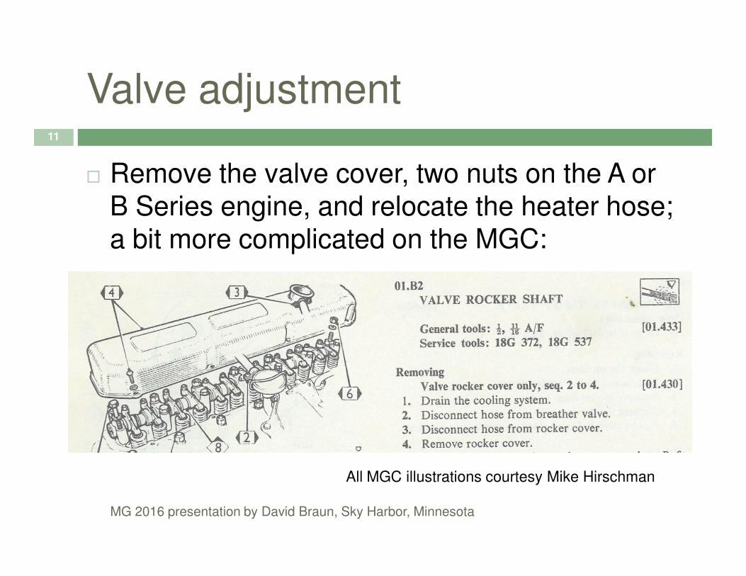
� Remove the valve cover, two nuts on the A or B Series engine, and relocate the heater hose; a bit more complicated on the MGC:
MG 2016 presentation by David Braun, Sky Harbor, Minnesota
All MGC illustrations courtesy Mike Hirschman
Valve adjustment12
� Put the car in fourth gear and on a level surface, with the parking brake ‘off’
� Pull the car forward until one rocker’s adjusting screw and nut is noticeably higher than the
MG 2016 presentation by David Braun, Sky Harbor, Minnesota
screw and nut is noticeably higher than the others- that valve is fully open
� Adjust the OPPOSING rocker using the ‘rule of nine’ or the ‘rule of 13’ depending on the engine
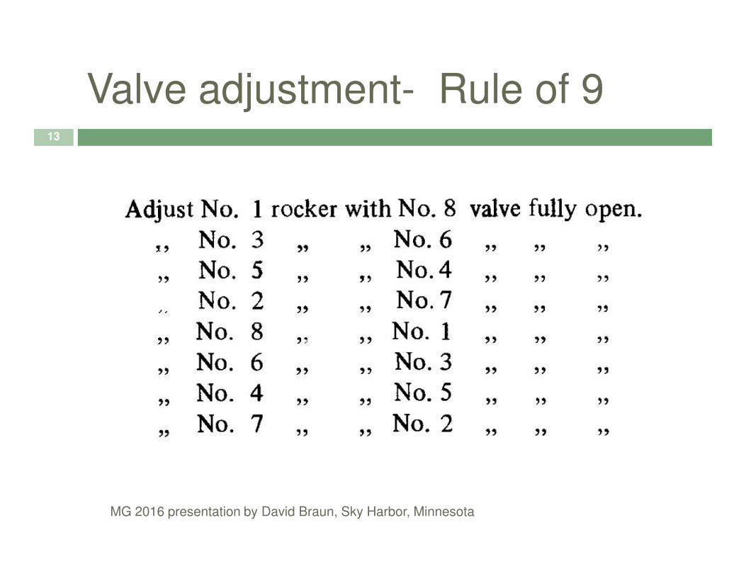
Valve adjustment- Rule of 913
MG 2016 presentation by David Braun, Sky Harbor, Minnesota

Valve adjustment- Rule of 1314
MG 2016 presentation by David Braun, Sky Harbor, Minnesota

Valve adjustment15
A or B Series
MG 2016 presentation by David Braun, Sky Harbor, Minnesota

Valve adjustment- Go No-Go16
� Check the clearance of the rocker on the valve
� .014 inch feeler gauge should slip in
� .016 inch feeler gauge should not
� By elimination, clearance is .015 inch
MG 2016 presentation by David Braun, Sky Harbor, Minnesota
� By elimination, clearance is .015 inch
� This method removes much of the guess work of how the clearance should ‘feel’
B and C series A series 1500 (BL Series)
Go .014 inch .011 inch .009 inch
No go .016 inch .013 inch .011 inch
Desired .015 inch .012 inch .010 inch
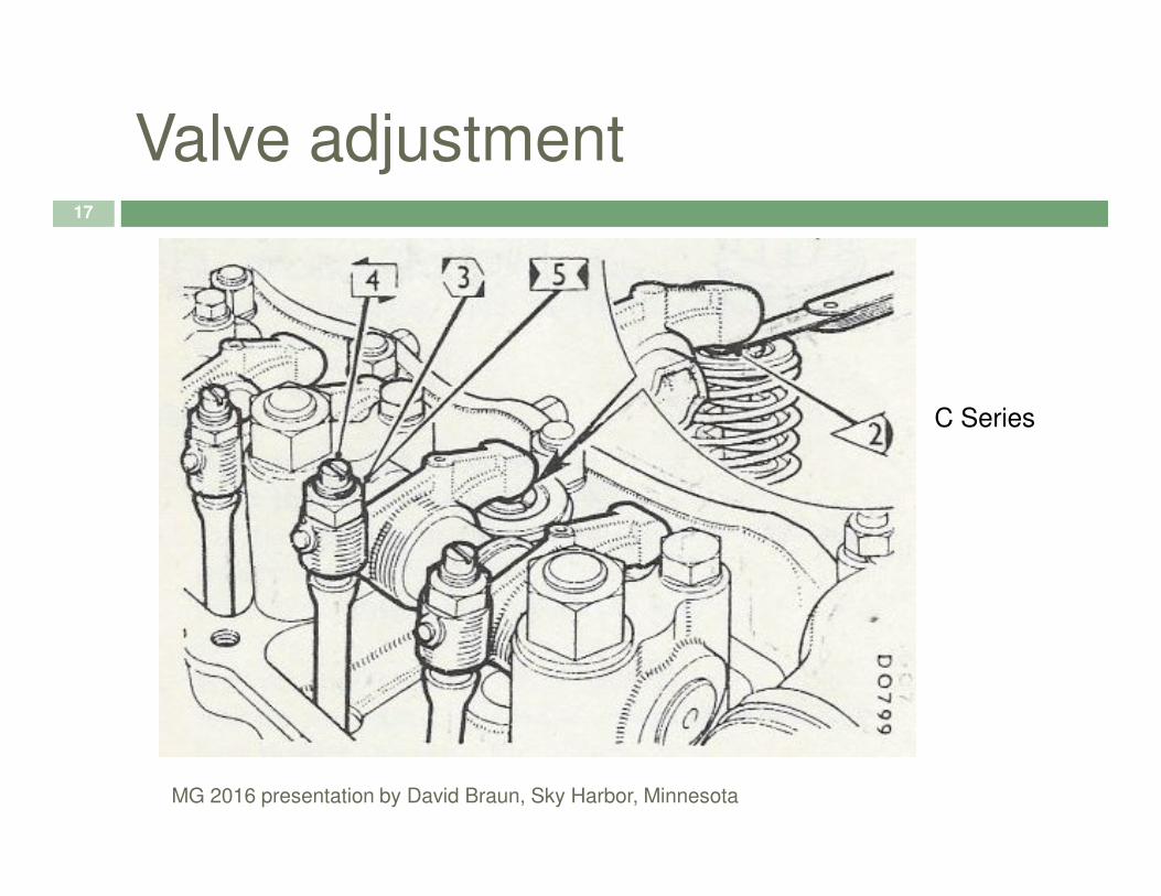
Valve adjustment17
C Series
MG 2016 presentation by David Braun, Sky Harbor, Minnesota
Valve adjustment18
� Look at the ‘Rule of nine’ or ‘Rule of 13’ table and find the NEXT valve that will be open
� Hang the box end of a wrench on that valve
� Pull car forward until the wrench is at its
MG 2016 presentation by David Braun, Sky Harbor, Minnesota
� Pull car forward until the wrench is at its highest point (valve open)
� This makes finding the point at which to adjust the opposing closed valve clearance easier
� You can also turn the crankshaft pulley nut to rotate the engine to the next position
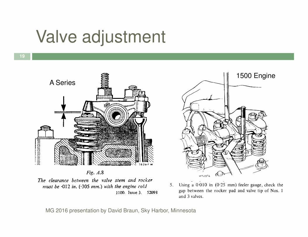
Valve adjustment19
A Series 1500 Engine
MG 2016 presentation by David Braun, Sky Harbor, Minnesota

Valve adjustment20
� If you need to adjust a valve (or two or three…)
MG 2016 presentation by David Braun, Sky Harbor, Minnesota
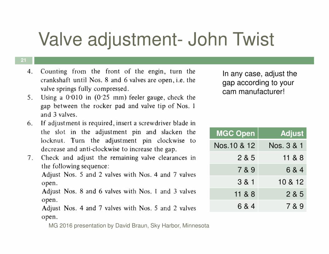
Valve adjustment- John Twist21
In any case, adjust the
gap according to your
cam manufacturer!
MG 2016 presentation by David Braun, Sky Harbor, Minnesota
MGC Open Adjust
Nos.10 & 12 Nos. 3 & 1
2 & 5 11 & 8
7 & 9 6 & 4
3 & 1 10 & 12
11 & 8 2 & 5
6 & 4 7 & 9

Valve Adjustment- Clik Adjust22
� Some folks have tried the “Clik-Adjust” tool
� It seems to offer a good way to hold the valve adjuster still when you tighten the nut
� Counting the ‘clicks’
MG 2016 presentation by David Braun, Sky Harbor, Minnesota
� Counting the ‘clicks’ can compensate for a worn adjuster andvalve interface.
Picture courtesy Bob Lewis

With each gulp of air controlled by the intake valve and movement of the piston, fuel also enters
When the mixture is compressed, it is ready for ignition
Fire
23
When the mixture is compressed, it is ready for ignition
Points allow the coil to discharge a powerful voltage to the spark plugs
Flame fronts, being a constant phenomenon must be advanced, or start sooner, the faster the engine is turning
All this happens courtesy of the ignition system
MG 2016 presentation by David Braun, Sky Harbor, Minnesota
Spark24
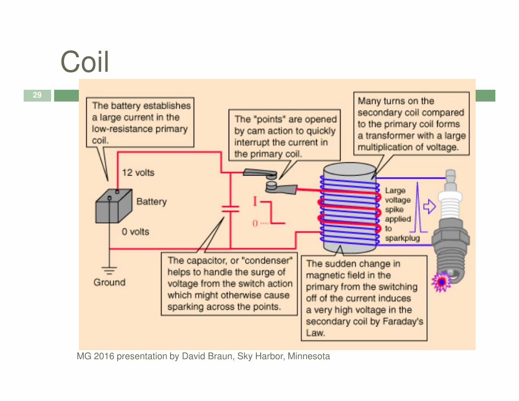
� Potential for spark comes from your car’s coil
� As the points open, the field associated with the primary coil collapses
� By inductance, the secondary field in the coil is
MG 2016 presentation by David Braun, Sky Harbor, Minnesota
� By inductance, the secondary field in the coil is energized
� The secondary coil is what generates the spark across the spark plug gap
� A condenser is present to protect the points from (arcing) pitting and wear
Distributor25
� The distributor has the following jobs:
� Create the spark by opening and closing the points
� Direct the spark at the spark plug that is on the
MG 2016 presentation by David Braun, Sky Harbor, Minnesota
� Direct the spark at the spark plug that is on the compression stroke 1-3-4-2 CCW; or 1-5-3-6-2-4 CCW (C Series)
� Advance the spark so the maximum cylinder pressure due to combustion occurs as the cylinder is traveling downward

Distributor Pictorial26
4 3 2 1
1-5-3-6-2-4 CCW Series C
6 5 Front �
MG 2016 presentation by David Braun, Sky Harbor, Minnesota
4 3 2 1
1-3-4-2 CCW Series A and
B
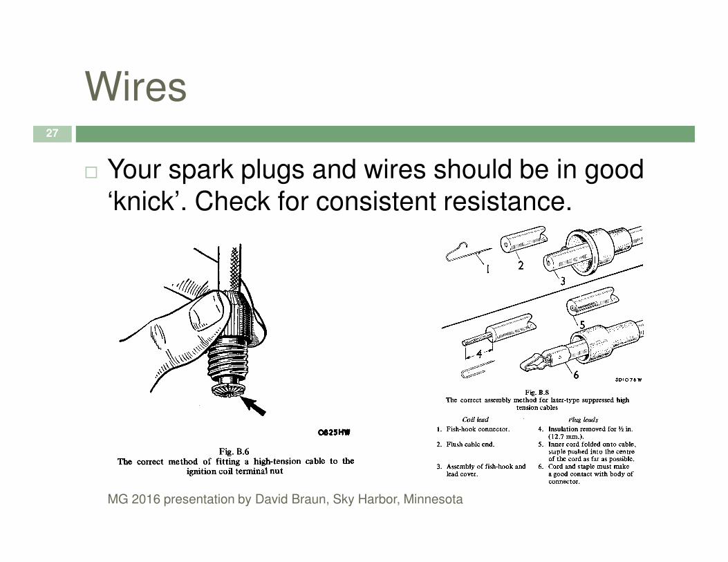
Wires27
� Your spark plugs and wires should be in good ‘knick’. Check for consistent resistance.
MG 2016 presentation by David Braun, Sky Harbor, Minnesota

Spark Gap28
� Gap your spark plugs to .025 inch
MG 2016 presentation by David Braun, Sky Harbor, Minnesota
Coil29
MG 2016 presentation by David Braun, Sky Harbor, Minnesota

Coil Information30
� Know your coil values:
� Some coils are meant to be fired with a reduced voltage (about 6-8 volts), delivered by means of a ballasted resistor wire; however while starting they receive a full 12 volts as an
MG 2016 presentation by David Braun, Sky Harbor, Minnesota
while starting they receive a full 12 volts as an assist
� These coils have resistance across the terminals of 1.3 to 1.8 Ω; normal coils will show 3 to 3.6 Ω
� Set up your power to your coil accordingly
Points31
� Adjusting points affects timing, adjust points first
� Loosen points plate
� Use go, no-go method of slipping in a .014
MG 2016 presentation by David Braun, Sky Harbor, Minnesota
� Use go, no-go method of slipping in a .014 inch feeler gauge, and then trying a .016 feeler gauge
� If the .014 goes in, and the .016 won’t; you must be at .015 inch point gap
� Tighten points plate
Adjusting Points32
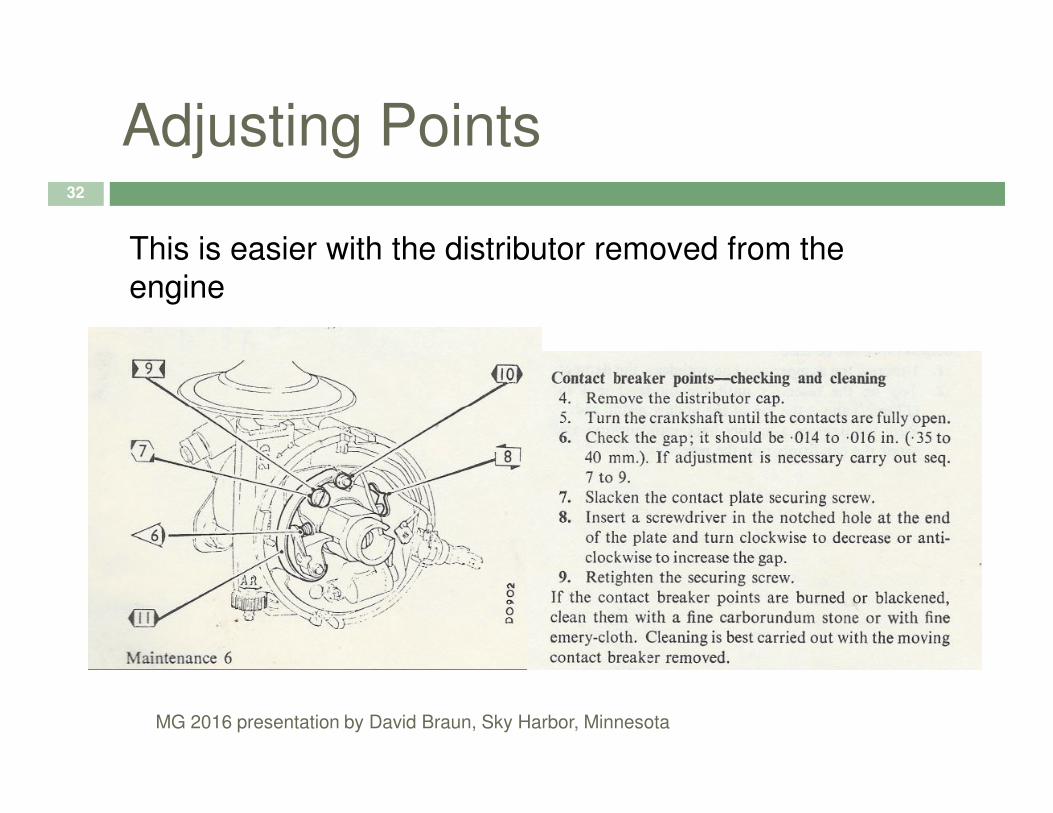
This is easier with the distributor removed from the
engine
MG 2016 presentation by David Braun, Sky Harbor, Minnesota

Reinstalling the Distributor33
� The distributor is easy to reinstall
MG 2016 presentation by David Braun, Sky Harbor, Minnesota

Clamp Position34
MG 2016 presentation by David Braun, Sky Harbor, Minnesota

Points Closed is Dwell35
� You can check your point setting with a Dwell Meter
� Dwell is the amount of time in the ignition cycle the points are closed
MG 2016 presentation by David Braun, Sky Harbor, Minnesota
the points are closed
� Dwell meters can be inaccurate as they age so use with a grain of salt
� Dwell on an A or B Series is about 60°± 3°;on a C Series is about 35°± 2°; and on a 1500 Series is about 39°± 1°

Points Closed is Dwell36
� Dwell
MG 2016 presentation by David Braun, Sky Harbor, Minnesota
Spark Advance37
� Spark advance is needed to provide the combustion at the peak cylinder pressure
� The distributor has mechanical advance and often, vacuum advance (rarely, vacuum retard)
Because the distributor rotates at half engine
MG 2016 presentation by David Braun, Sky Harbor, Minnesota
� Because the distributor rotates at half engine speed, 10° of distributor advance is the same as 20° of crankshaft advance
� We measure timing in crankshaft degrees
� Advance is programmed in for us in the distributor

Static Timing 38
� Place a light bulb between the distributor terminal and the coil terminal on your system
� Turn engine to 8-10° before TDC, #1 firing
� Tweek the rotor clockwise, switch on ignition
MG 2016 presentation by David Braun, Sky Harbor, Minnesota
� Tweek the rotor clockwise, switch on ignition
� Turn the distributor counter-clockwise until points block is just before the cam lobe
� Turn the distributor clockwise until bulb lights
� Tighten distributor locking nut

Static Timing Technique39
MG 2016 presentation by David Braun, Sky Harbor, Minnesota
Spark Plug Reinstallation40
� A dab of anti-seize is popular, carefully wipe your hands or the next thing you touch will be permanently stained!
� Tighten the plugs until they are snug. New plugs have a different feel than old plugs
MG 2016 presentation by David Braun, Sky Harbor, Minnesota
plugs have a different feel than old plugs
� Do not crack the ceramic
� Attach the wires starting with the ‘marked’ number 1; proceeding counter clockwise around the distributor 3-4-2, (or 5-3-6-2-4) make sure the main coil wire is intact
Dynamic Timing41
� Highlight the crank pulley marks with white paint
� Place timing-light inductive pickup on number one spark plug wire
Attach timing-light leads to the brown wires at
MG 2016 presentation by David Braun, Sky Harbor, Minnesota
� Attach timing-light leads to the brown wires at the fuse block and a good ground respectively
� Disconnect and plug vacuum advance source
� Loosen distributor, start engine, and turn distributor until desired timing is indicated on marks usually about 15° BTDC @<1,000 RPM
All-In Advance42
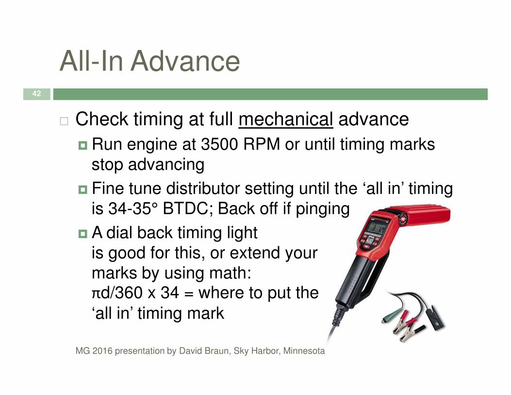
� Check timing at full mechanical advance
� Run engine at 3500 RPM or until timing marks stop advancing
� Fine tune distributor setting until the ‘all in’ timing
MG 2016 presentation by David Braun, Sky Harbor, Minnesota
is 34-35° BTDC; Back off if pinging
� A dial back timing lightis good for this, or extend your marks by using math:πd/360 x 34 = where to put the
‘all in’ timing mark

Timing Marks A and B Series43
A and B
Series
MG 2016 presentation by David Braun, Sky Harbor, Minnesota
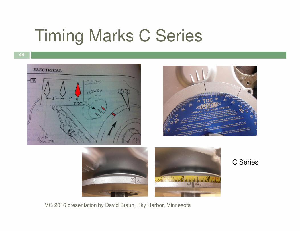
Timing Marks C Series44
MG 2016 presentation by David Braun, Sky Harbor, Minnesota
C Series

Timing Marks 1100 or 130045
A Series in
MG 2016 presentation by David Braun, Sky Harbor, Minnesota
A Series in
1100 or 1300
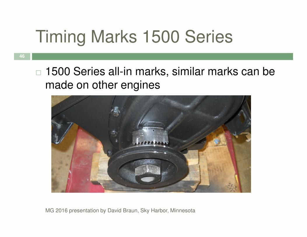
Timing Marks 1500 Series46
� 1500 Series all-in marks, similar marks can be made on other engines
MG 2016 presentation by David Braun, Sky Harbor, Minnesota

Recheck and Record47
� Once the ‘all-in’ firing advance is set (34-35°BTDC) and pinging checked, go back to the idle setting and re-check your timing
� Write down the setting and the idle RPM
MG 2016 presentation by David Braun, Sky Harbor, Minnesota
� Write down the setting and the idle RPM
� This is the proper timing at idle for your engine with your distributor, and points setting
� You can use this value to quickly check or set timing in the future
� Reconnect your vacuum advance

Early B Series Tuning Data48
MG 2016 presentation by David Braun, Sky Harbor, Minnesota

Later B Series Tuning Data49
MG 2016 presentation by David Braun, Sky Harbor, Minnesota

C Series Tuning Data50
MG 2016 presentation by David Braun, Sky Harbor, Minnesota
1500 Series Tuning Data51
� The Midget 1500 used (I think) three different distributors and timing specs, including some retard specs
� If you are setting up to stock; use the manual’s settings
MG 2016 presentation by David Braun, Sky Harbor, Minnesota
settings
� If you have modified your engine, start at 10°BTDC and check for ‘all in’ timing with vacuum disconnected – Adjust accordingly
� You may choose to run with the vacuum retard disconnected

The engine needs an air/fuel ratio that is slightly rich at idle and full acceleration; and close to stoichometric at cruise
Fuel
52
stoichometric at cruise
The job of delivering the fuel to the air coming into the engine belongs to the carburetors
The carburetors are always the last item to be adjusted in a tune-up
MG 2016 presentation by David Braun, Sky Harbor, Minnesota

Stoichometric A/F53
� What is Stoichometric?
� Compare at Best Power
� Compare at idle
MG 2016 presentation by David Braun, Sky Harbor, Minnesota

Basic Semi Side Draft54
� The SU (and Zenith Stromberg) Carburetors have four basic moving parts
MG 2016 presentation by David Braun, Sky Harbor, Minnesota

Four Basic Moving Parts55
� The float and float bowl needle
� The jet for setting and enrichment
� The piston and metering needle to set running condition A/F mixture
MG 2016 presentation by David Braun, Sky Harbor, Minnesota
condition A/F mixture
� The throttle disk and spindle to regulate air into the engine
Theory of Operation56
� The piston rises, finds equilibrium and falls based on the positive pressure under the piston
� Once the pressure under the piston is
MG 2016 presentation by David Braun, Sky Harbor, Minnesota
� Once the pressure under the piston is equalized by the pressure in the suction chamber, the piston becomes stationary
� The entire range of airflow can have a ‘matching’ fuel input based on the tapered needle rising and falling with the piston

Theory of Operation57
� This equalization of pressure above and below the piston gave rise to the Zenith Stromberg term ‘Constant Depression’ hence their carburetors are typically called ‘150-CD’ or
MG 2016 presentation by David Braun, Sky Harbor, Minnesota
‘175-CD’
� Where SU decided to create this carefully metered air bleed by machining parts to close tolerances, Zenith Stromberg uses a rubber diaphragm
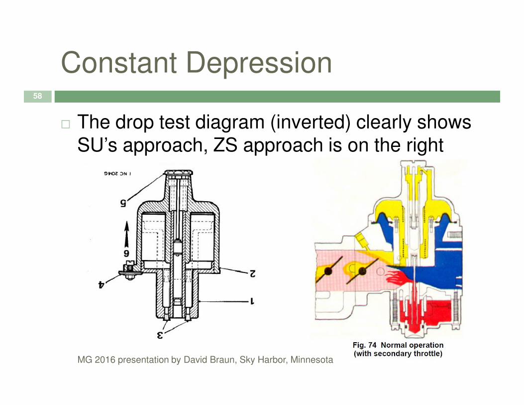
Constant Depression58
� The drop test diagram (inverted) clearly shows SU’s approach, ZS approach is on the right
MG 2016 presentation by David Braun, Sky Harbor, Minnesota

Needles Program Entire Range59
� With a given set of needles a stock engine will get the proper amount of fuel for any condition ‘programmed’ into the needles
� For non-stock engines a bit of searching and
MG 2016 presentation by David Braun, Sky Harbor, Minnesota
� For non-stock engines a bit of searching and imagination may be needed
� The factory provided guidance for standard, rich, and lean settings
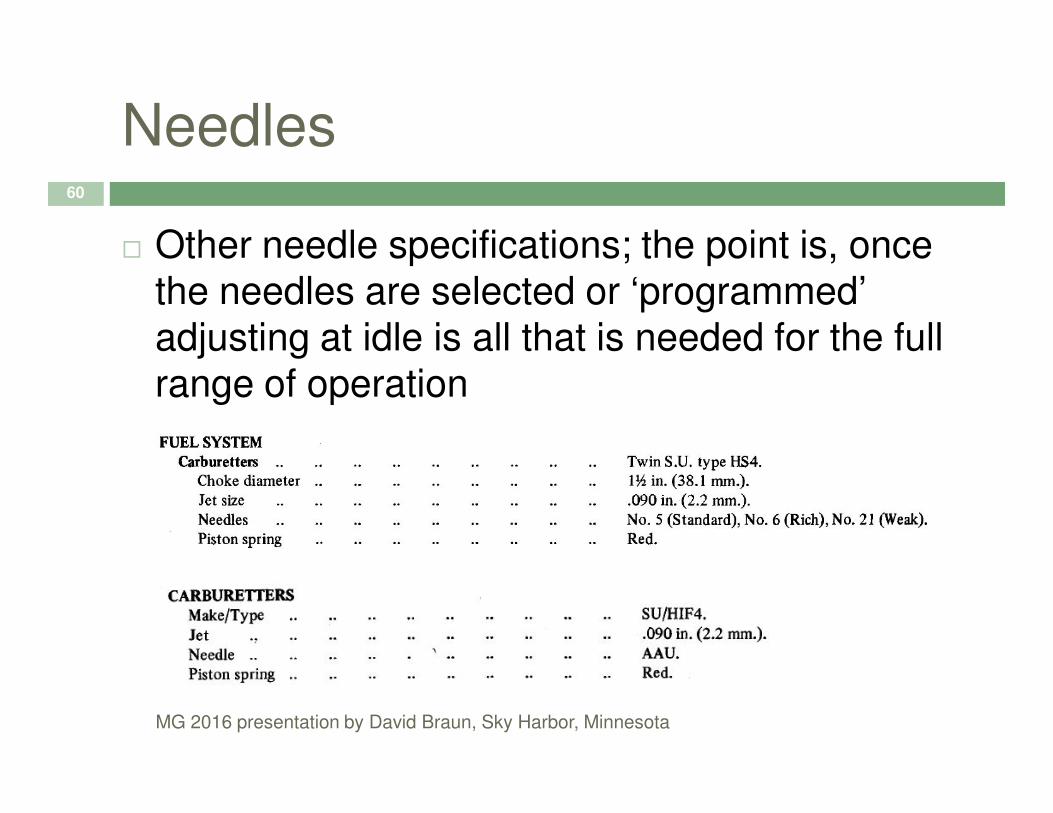
Needles60
� Other needle specifications; the point is, once the needles are selected or ‘programmed’ adjusting at idle is all that is needed for the full range of operation
MG 2016 presentation by David Braun, Sky Harbor, Minnesota

Needles Comparator61
� On-line needle comparator: www.MintyLamb.co.uk
MG 2016 presentation by David Braun, Sky Harbor, Minnesota

Fixed and Biased Difference62
� Original needles are ‘fixed’ and shorter
� Fixed requires ‘centering the jet’
� Later needles are ‘biased’ orspring loaded and longer
MG 2016 presentation by David Braun, Sky Harbor, Minnesota
spring loaded and longer
� Except for idle, typically only stations 3-10 are utilized

Depth of Fuel in the Jet63
� The depth of fuel in the jet has an impact on how much fuel is placed into the airstream via the annulus formed by the jet and the needle
� The column of fuel in the float chamber on external float carburetors like the H or HS
MG 2016 presentation by David Braun, Sky Harbor, Minnesota
external float carburetors like the H or HS series controlled the depth
� Directly in integral float carburetors like the HIF series or the ZS
� The depth of fuel should be 0.16 ±0.04 inches below the height of the bridge

Depth of Fuel in the Jet64
MG 2016 presentation by David Braun, Sky Harbor, Minnesota
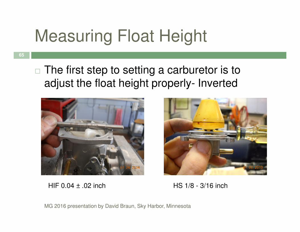
Measuring Float Height65
� The first step to setting a carburetor is to adjust the float height properly- Inverted
MG 2016 presentation by David Braun, Sky Harbor, Minnesota
HIF 0.04 ± .02 inch HS 1/8 - 3/16 inch
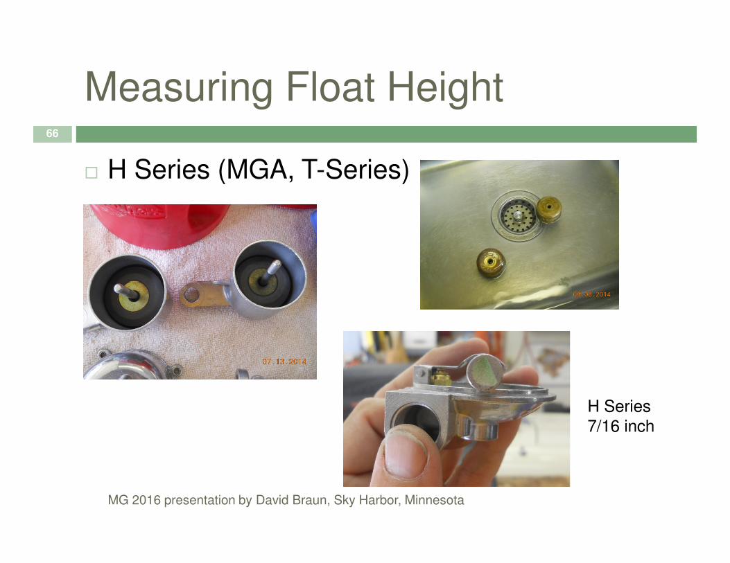
Measuring Float Height66
� H Series (MGA, T-Series)
MG 2016 presentation by David Braun, Sky Harbor, Minnesota
H Series
7/16 inch
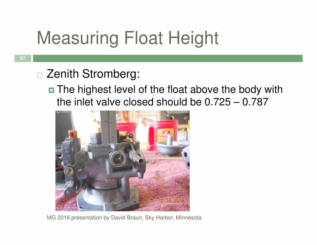
Measuring Float Height67
� Zenith Stromberg:
� The highest level of the float above the body with the inlet valve closed should be 0.725 – 0.787
MG 2016 presentation by David Braun, Sky Harbor, Minnesota

Float Needle Valves68
� Two common types:
MG 2016 presentation by David Braun, Sky Harbor, Minnesota
A word about Gross
Jet float valves
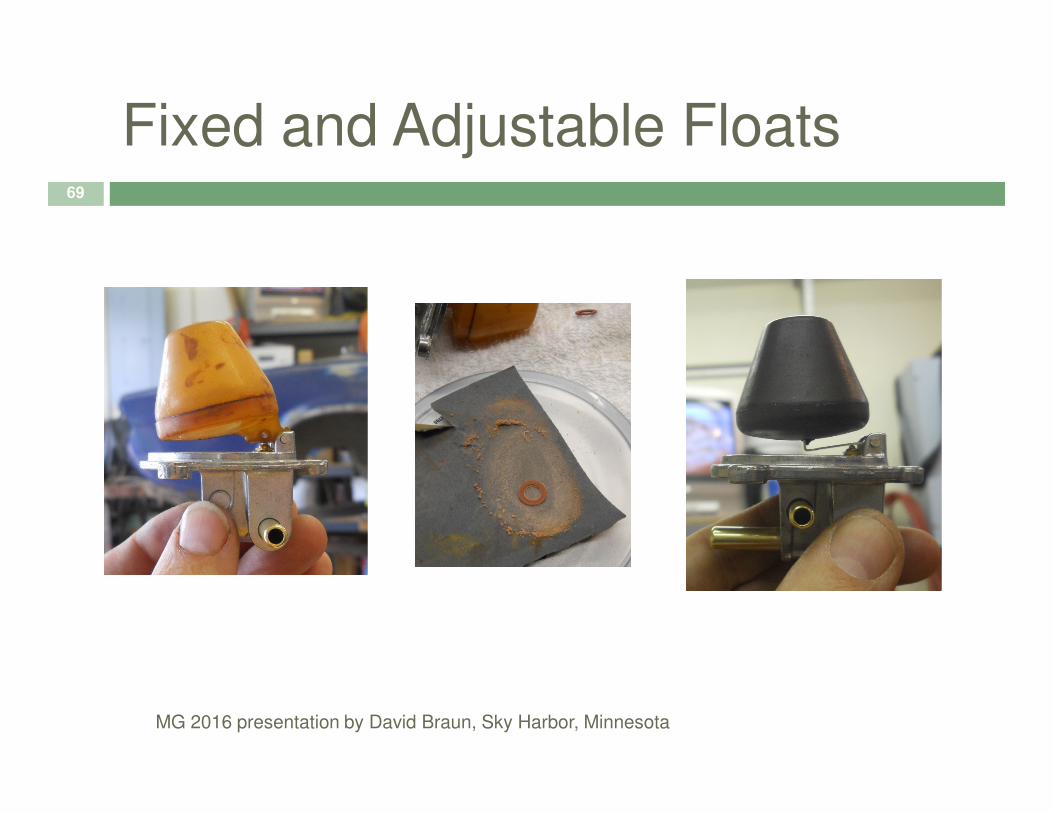
Fixed and Adjustable Floats69
MG 2016 presentation by David Braun, Sky Harbor, Minnesota

Verify Fuel Height in Jet70
� To check, fuel level height:
� Remove the suction chambers and the pistons, keeping them organized
� Lower the jet position as you would for enrichment and measure the level of the jet when it is level with the fuel- use a dial caliper
MG 2016 presentation by David Braun, Sky Harbor, Minnesota
and measure the level of the jet when it is level with the fuel- use a dial caliper
� Adjust float dimension as necessary
� Remove fuel from float bowl with a suction bulb if you need to readjust the fuel level; use the car’s fuel pump to refill the float bowl
� Not as critical on ZS carburetors
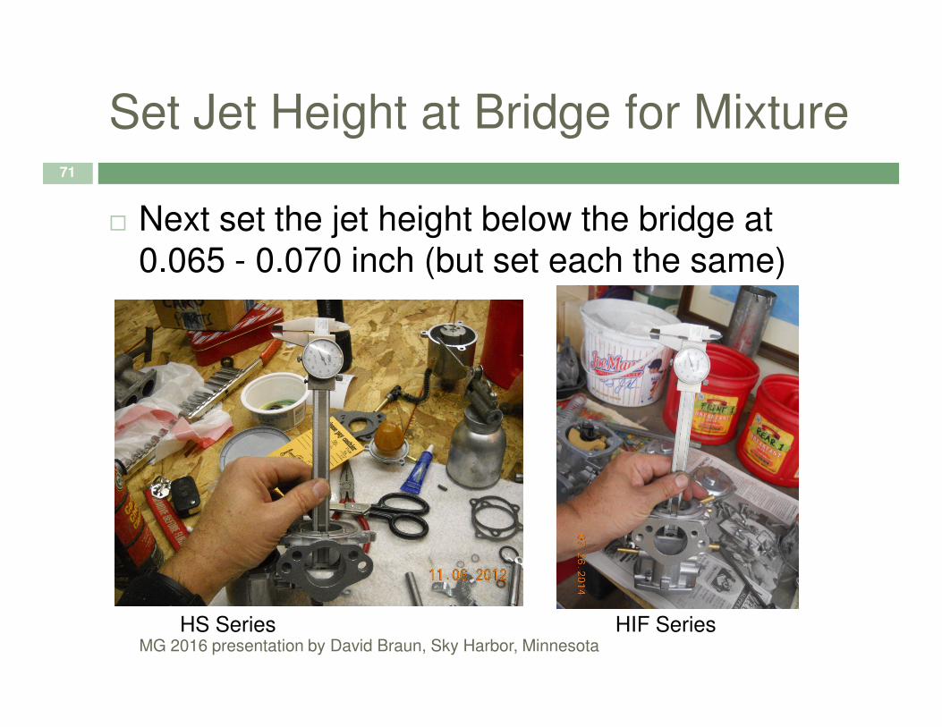
Set Jet Height at Bridge for Mixture71
� Next set the jet height below the bridge at 0.065 - 0.070 inch (but set each the same)
MG 2016 presentation by David Braun, Sky Harbor, MinnesotaHS Series HIF Series

Adjusting Jet Height72
� On SU H and HS Series carburetors the adjusting nut is below the jet bearing tube
� On SU HIF carburetors the mixture screw goes counter clockwise to raise (lean) the jet and
MG 2016 presentation by David Braun, Sky Harbor, Minnesota
counter clockwise to raise (lean) the jet and clockwise to lower (enrichen) the jet
� On ZS carburetors you use the tool, a 1/8 Allan wrench within a pinned tube; note- not all ZS carburetors have adjustable jets; turn the wrench clockwise to enrichen the jet
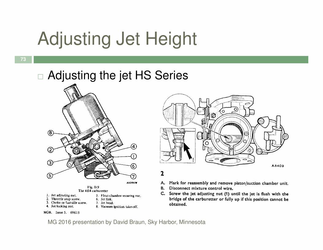
Adjusting Jet Height73
� Adjusting the jet HS Series
MG 2016 presentation by David Braun, Sky Harbor, Minnesota
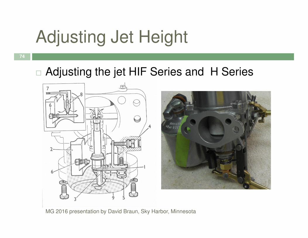
Adjusting Jet Height74
� Adjusting the jet HIF Series and H Series
MG 2016 presentation by David Braun, Sky Harbor, Minnesota
Balance Multiple Carburetors75
� Reinstall the suction chambers and pistons
� With the air cleaners off, start the engine and allow it to warm up
� Balance the airflow between the two carburetors by loosening the connection shaft and adjust the idle of each with a Unisyn, cat’s whiskers or
MG 2016 presentation by David Braun, Sky Harbor, Minnesota
by loosening the connection shaft and adjust the idle of each with a Unisyn, cat’s whiskers or listening tube
� Retighten the connection between the carburetors
� From here, make all idle adjustments equally on both carburetors
� Make sure the fast idle circuit is not fouling the adjustment

Balance76
MG 2016 presentation by David Braun, Sky Harbor, Minnesota
Adjust the Mixture H or HS
Series77
� Allow the engine to idle at 850-900 RPM; reset if necessary (timing also affects idle)
� Raise the adjusting nut two flats and note any RPM changes
MG 2016 presentation by David Braun, Sky Harbor, Minnesota
RPM changes
� If there are none, lower the adjusting nut four flats and note any changes
� Where you find a rise in RPM stop there and lower the adjusting nut one flat for a slightly richer setting
� Always count your flats!
Adjust the Mixture HIF Series78
� On HIF Series Carburetors turn the mixture adjusting screw ¼ turn at a time out and note if you hear a rise in RPM
� If not, turn the return the adjusting screw to the
MG 2016 presentation by David Braun, Sky Harbor, Minnesota
� If not, turn the return the adjusting screw to the original position continue to turn the screw in further ¼ turn at a time and note if you hear a rise in RPM
� Turn the adjusting screw an additional ¼ turn in once the rise in RPM is found
Dampener Oil79
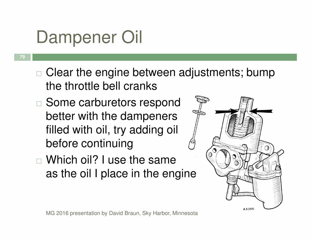
� Clear the engine between adjustments; bump the throttle bell cranks
� Some carburetors respondbetter with the dampeners
MG 2016 presentation by David Braun, Sky Harbor, Minnesota
better with the dampenersfilled with oil, try adding oil before continuing
� Which oil? I use the same as the oil I place in the engine
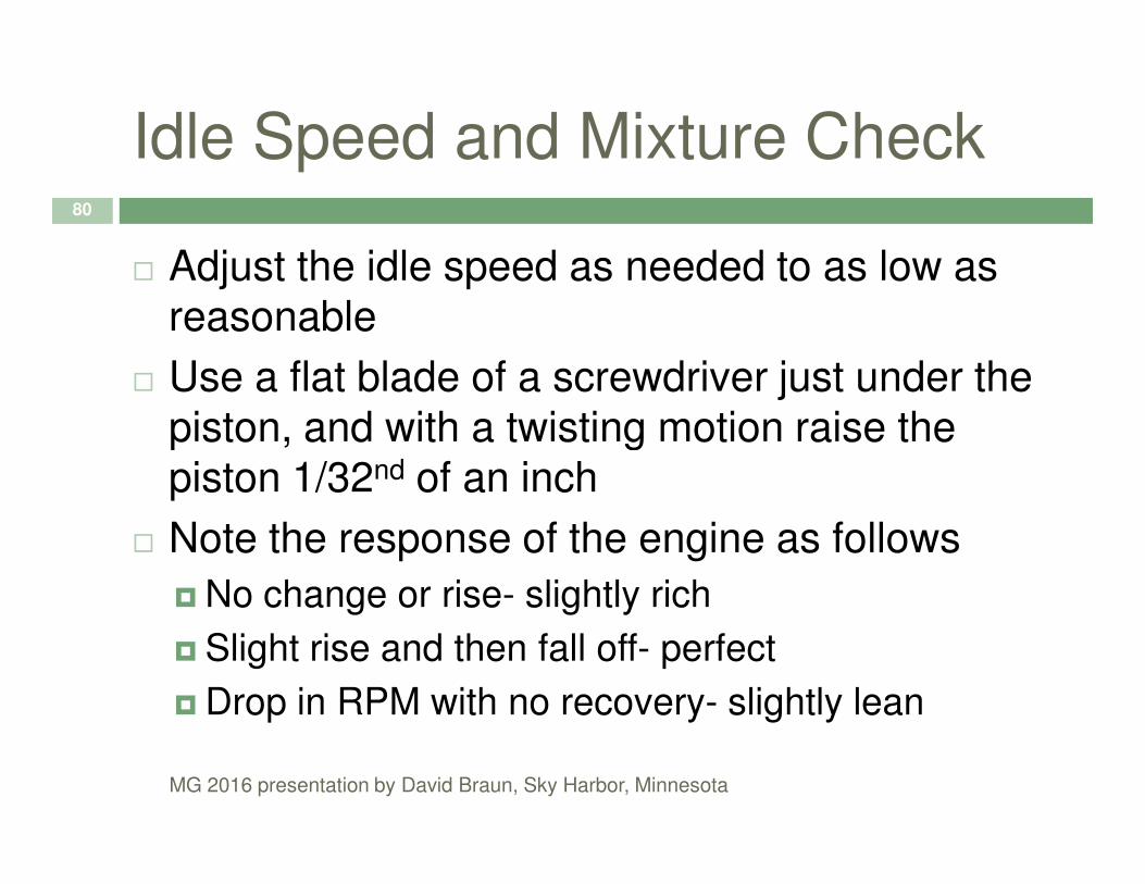
Idle Speed and Mixture Check80
� Adjust the idle speed as needed to as low as reasonable
� Use a flat blade of a screwdriver just under the piston, and with a twisting motion raise the
MG 2016 presentation by David Braun, Sky Harbor, Minnesota
piston, and with a twisting motion raise the piston 1/32nd of an inch
� Note the response of the engine as follows
� No change or rise- slightly rich
� Slight rise and then fall off- perfect
� Drop in RPM with no recovery- slightly lean
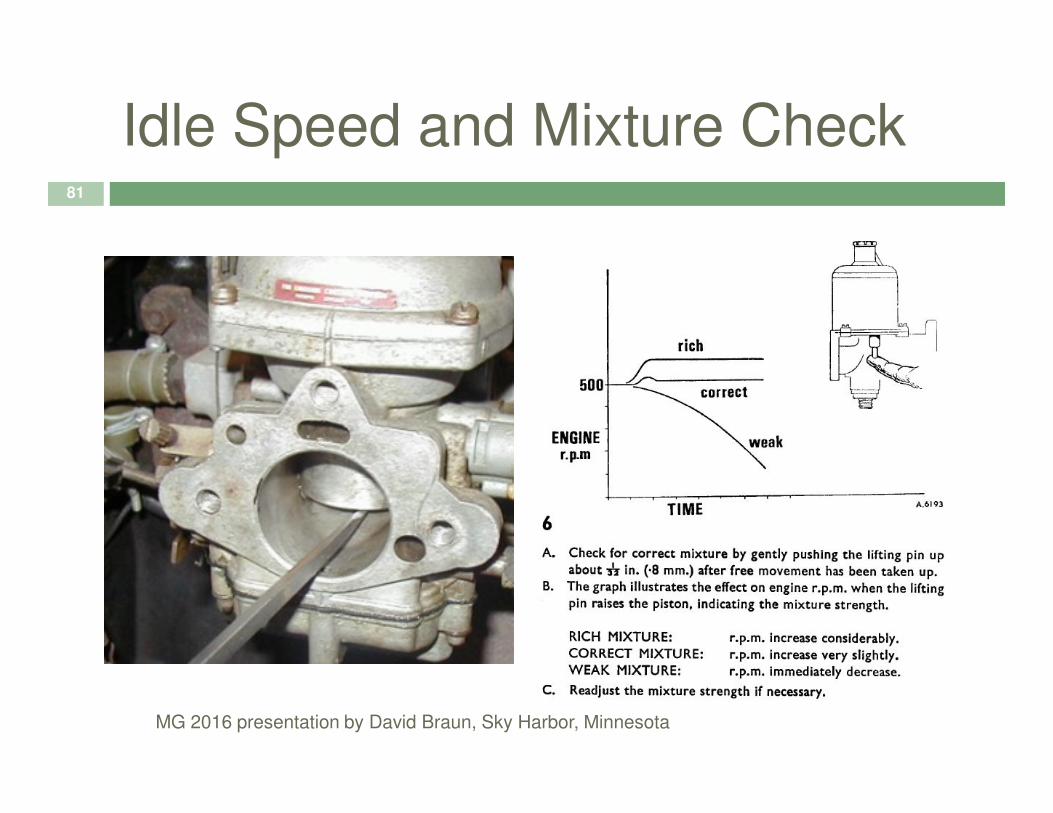
Idle Speed and Mixture Check81
MG 2016 presentation by David Braun, Sky Harbor, Minnesota

Verify Jet Height82
� Continuing for H, HS and HIF Series
� Again, remove the suction chamber and piston
� Measure the height of the jet below the bridge
� If it is less than .050 inches below the bridge,
MG 2016 presentation by David Braun, Sky Harbor, Minnesota
� If it is less than .050 inches below the bridge, your float level may be high
� If it is greater than .080 inches below the bridge your float level may be low
� Ideal range is .060 to .070 below the bridge
� Reinstall the suction chamber and piston

ZS Carburetor Tips83
� Special notes for ZS carburetors:
� The air bleed screw on the side of the carburetor is useful for trimming mixture
� The choke assembly is prone to sticking; make
MG 2016 presentation by David Braun, Sky Harbor, Minnesota
sure it is free
� Assure the rubber diaphragm is intact; never spray carburetor cleaner in a ZS carburetor; it may degrade the diaphragm
� Check the plug at the bottom of the float bowl

Adjust the Mixture CD Series84
� Adjusting the jet Zenith Stromberg10mm
locknut screw
Throttle stop
Fine idle screw
Course idle nut
MG 2016 presentation by David Braun, Sky Harbor, Minnesota
Spring loaded idle
speed screw

ZS Carburetor Procedure85
� Assumes no vacuum leaks
� Assumes choke is working
� Assumes stock needle and air cleaner
� Use the adjusting tool and set the needle so
MG 2016 presentation by David Braun, Sky Harbor, Minnesota
� Use the adjusting tool and set the needle so the barrel shaped carrier sits flush with the bottom of the piston
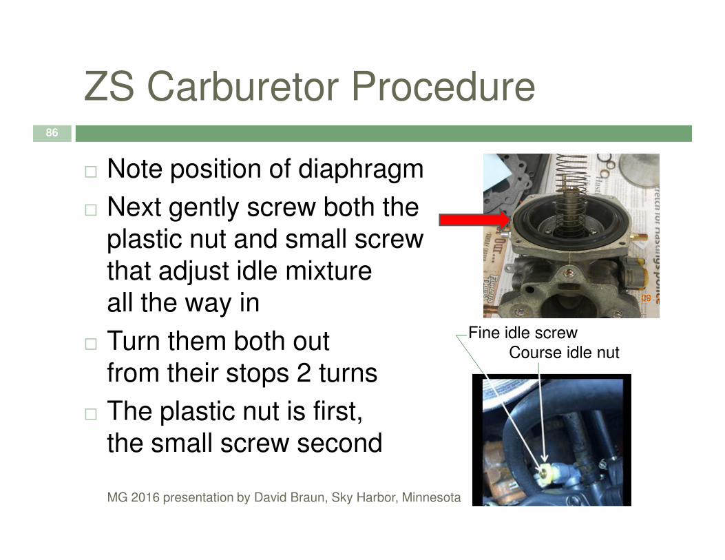
ZS Carburetor Procedure86
� Note position of diaphragm
� Next gently screw both theplastic nut and small screwthat adjust idle mixture
MG 2016 presentation by David Braun, Sky Harbor, Minnesota
that adjust idle mixtureall the way in
� Turn them both outfrom their stops 2 turns
� The plastic nut is first,the small screw second
Fine idle screw
Course idle nut

ZS Carburetor Procedure87
� Allow the engine to warm up
� Adjust the idle screw with the spring and bring the idle to 850-900 RPM
� Adjust the main idle stop (10mm nut stop nut)
MG 2016 presentation by David Braun, Sky Harbor, Minnesota
� Adjust the main idle stop (10mm nut stop nut)
� Adjust the fine center screw in the coarse nylon nut until the idle peaks and the engine smooths; adjust the idle screw with the spring to bring the idle to 850-900 RPM
� Readjust the main idle stop if needed
ZS Carburetor Procedure88
� If you run out of adjustment (three turns either way) on the center screw, move the coarse nylon nut slightly in or out as needed to give more fine adjustment
MG 2016 presentation by David Braun, Sky Harbor, Minnesota
� You probably don’t have to adjust the needle with the adjuster tool, but if you do, move it no more than a turn in either direction, CW to enrichen, CCW to lean
Record Your Numbers89
� Note the setting of the jet depth or ZS settings for future reference
� If your car accelerates nicely at a different setting, and gets reasonable mileage, no problems- every engine has different needs
MG 2016 presentation by David Braun, Sky Harbor, Minnesota
problems- every engine has different needs
� The important thingis to know thesettings for yourengine once youachieve them

We have identified the key concerns on setting up or tuning an engine; Breathing, Fire, Fuel
We have shown you some consistent approaches to
Hopefully-
90
We have shown you some consistent approaches to adjusting Breathing, Fire, Fuel and explained why the order is important
We have identified the differences between models so you can assist your friends
We have convinced you to keep notes of your efforts
Engage a mentor if you would like to learn more
MG 2016 presentation by David Braun, Sky Harbor, Minnesota

Back-up
91
MG 2016 presentation by David Braun, Sky Harbor, Minnesota

HIF by-pass92
� AdditionalHIF information
MG 2016 presentation by David Braun, Sky Harbor, Minnesota

HIF Linkage93
MG 2016 presentation by David Braun, Sky Harbor, Minnesota

94
MG 2016 presentation by David Braun, Sky Harbor, Minnesota

Piston Stops95
� Piston Stops
MG 2016 presentation by David Braun, Sky Harbor, Minnesota
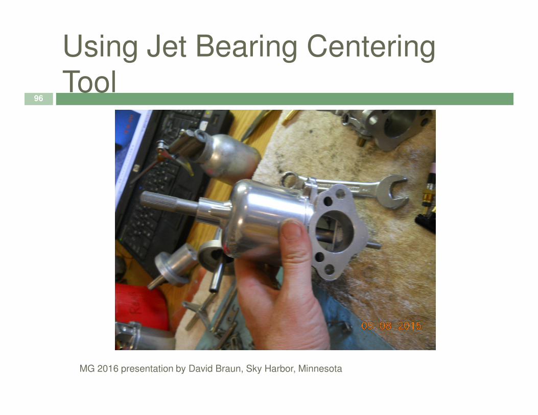
Using Jet Bearing Centering
Tool96
MG 2016 presentation by David Braun, Sky Harbor, Minnesota

HS2 Enrichment Linkage97
MG 2016 presentation by David Braun, Sky Harbor, Minnesota
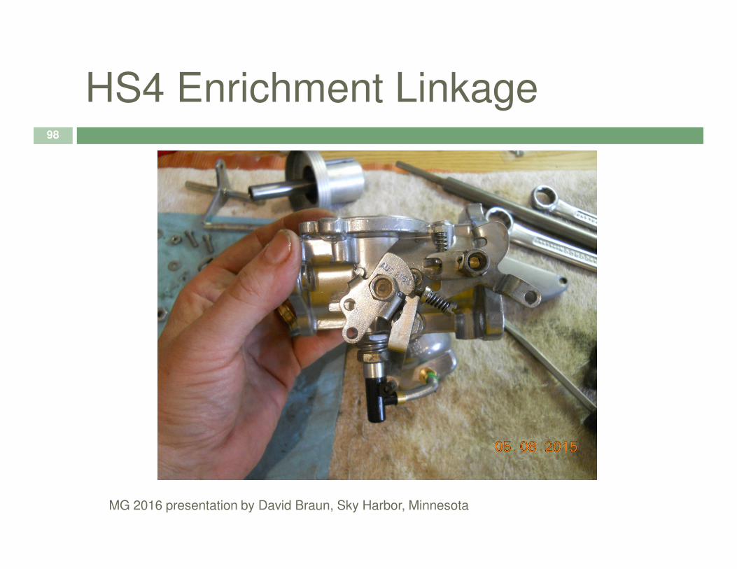
HS4 Enrichment Linkage98
MG 2016 presentation by David Braun, Sky Harbor, Minnesota

Proper Depth of Biased Needle99
MG 2016 presentation by David Braun, Sky Harbor, Minnesota

Transverse Tube Leaks100
� XPAG H Series
MG 2016 presentation by David Braun, Sky Harbor, Minnesota

XPAG Manifold Balancer Nut101
MG 2016 presentation by David Braun, Sky Harbor, Minnesota
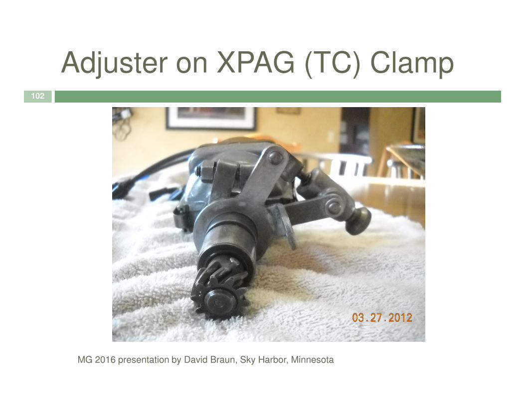
Adjuster on XPAG (TC) Clamp102
MG 2016 presentation by David Braun, Sky Harbor, Minnesota
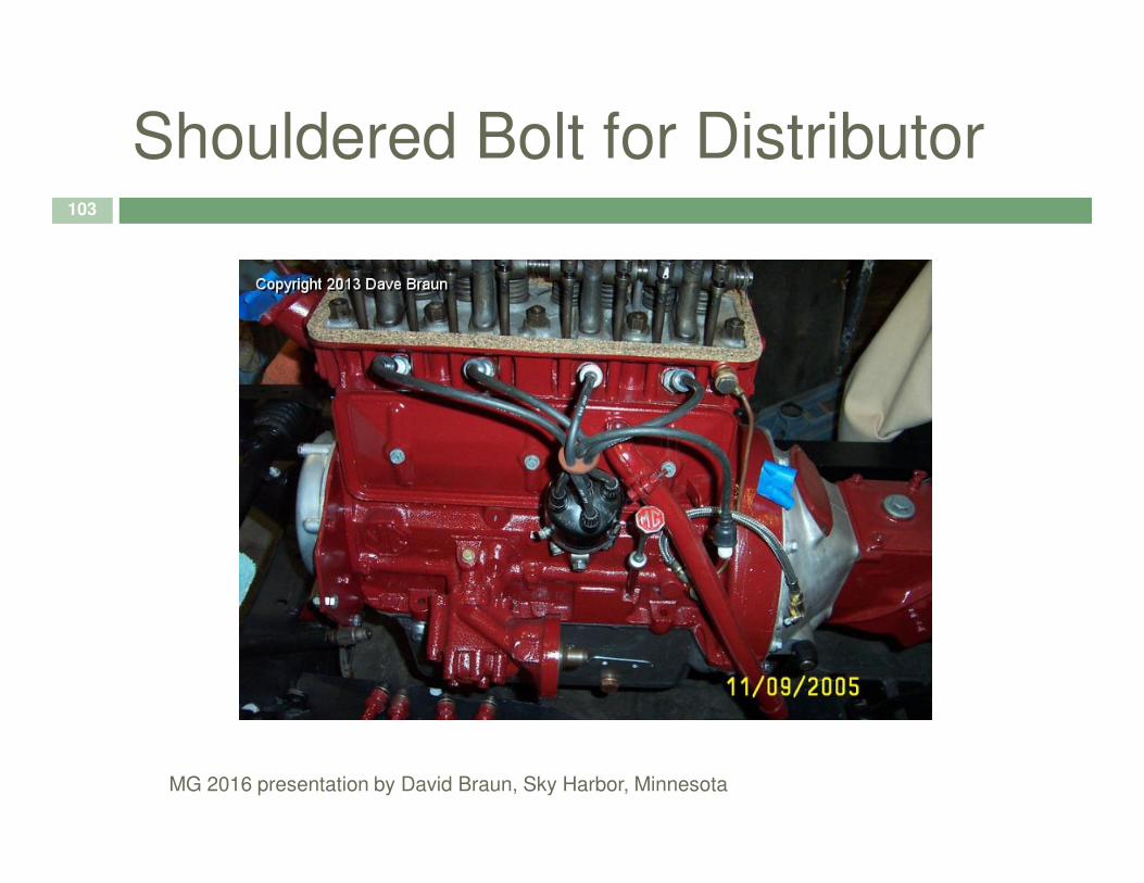
Shouldered Bolt for Distributor103
MG 2016 presentation by David Braun, Sky Harbor, Minnesota