100 Volts 0 Volts v o,x. x V(x) 50 150 100 200 50 Volts 200 Volts.
169
100 Volts 0 Volts v o,x
-
date post
20-Dec-2015 -
Category
Documents
-
view
250 -
download
6
Transcript of 100 Volts 0 Volts v o,x. x V(x) 50 150 100 200 50 Volts 200 Volts.

100 Volts
0 Volts
vo,x

x
V(x)
50
150
100
200
200 Volts

-200 Volts 200 Volts
z
ycoordinates
x

10 V 0 V
(note the perpendicular intersections)

10 V 0 V x
y
(line of symmetry is x-axis where y=0)

V(x,0)
yields
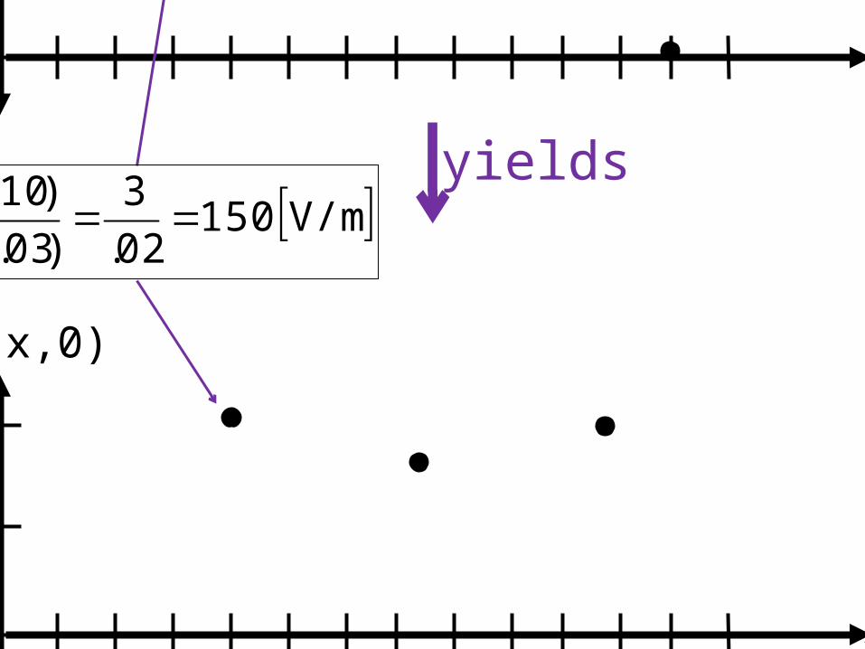
x (cm)
yields
Ex(x,0)
V/m 15002.
3
)03.05(.
)107(
x
V
x (cm)

x
U(x)potential energy
stableequilibrium(FNET = 0)
unstableequilibrium(FNET = 0)
negative slope(FNET to right)
positive slope(FNET to left)
A B
C D

x
U(x)potential energy
A: stableequilibrium C: unstable
Equilibrium
D: FNET to right
B: FNET to left
A B
C D

x
U(x)potential energy
A B
C D

x
V(x)electric potential
A Bbegin

x
y
+
Radial electric vector field of a charged conducting circle

x
+
y
_

_
y

x
y
_

y
U(x,y)potential energy
FNET to right and forward)
x
dotted lines showconstant energy

y
U(x,y)potential energy
FNET to right and forward)x
(dotted lines showconstant energy:“equipotentials”)
(equipotentialscloser where steepest)

y
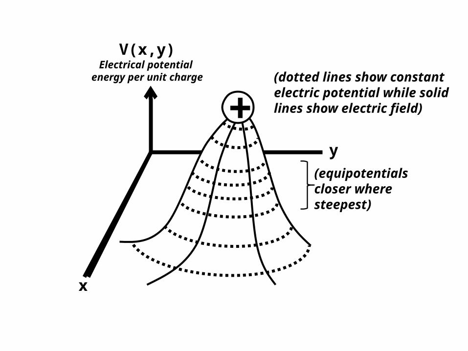
V(x,y)electric potential
(potential energy per unit charge)
E(x,y)x
dotted lines showconstant electric
potential+
+
solid lines showelectric field
arrow shows electricfield direction on
positive test charge

y
V(x,y)
x
(dotted lines show constant electric potential)
+
+
(solid lines showelectric field)
(arrow shows forceon test charge)
++
y
V(x,y)Electrical potential
energy per unit charge
x
(equipotentialscloser where steepest)
+(dotted lines show constant electric potential while solid lines show electric field)

y
V(x,y)
x
(dotted lines show constant electric potential)
+(solid lines showelectric field)

y
V(x,y)
x
dotted lines showconstant electric
potential+solid lines showelectric field

y
+

y

x
yV=4 volts
A
B
q

V=7 volts
V=5 voltsE=?

V=7 volts
V=5 voltsE=?
d = 2 cm

100 V/m
x
y
Q = 35o
Q must be estimated ormeasured with a protractorto calculate the legs (x andY components of E).
57 V/m
82 V/m

10o15o
30o
45o
60o75o

y
V(x,y)
E(x,y)
x
dotted lines showconstant electric
potential
_
+
solid lines showelectric field
arrow shows electricfield direction on
positive test charge

y
V(x,y)
x
_
+

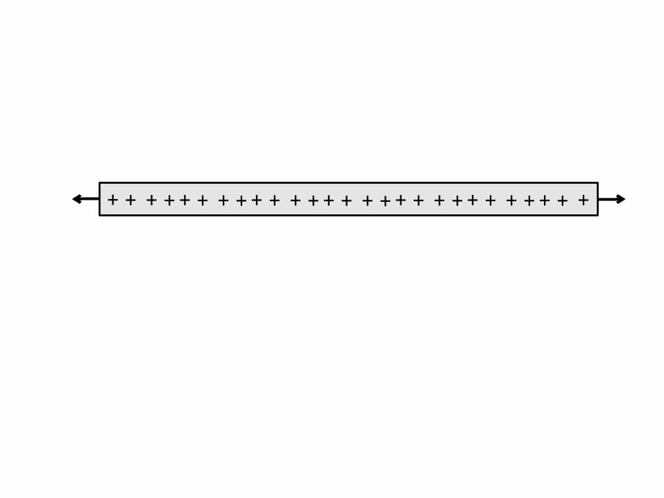
+ + + ++ + + ++ + + ++ + + ++ + + ++ + + ++ + +

VI
LACROSS SECTION

BA
TT
ER
Y
+
BA
TT
ER
Y
+
ITOTAL
IA IB IC
IE
ID
BA
TT
ER
Y
+
BA
TT
ER
Y
+

BA
TT
ER
Y
+ PU
MP
(handle)(spinning
paddlewheel)ee e e e
e
e
e
e
e e
e
eee

RVsourceR
RVsourceR
ab c
de
fg
h

RVsource
R
Vsource
R
resistorsin series
RVsourceR
resistorsin parallel
RVsource

6 W3 V
3V 6 W

BATTERY+
the ground
BATTERY+
the ground
current can never flow current may flow(depending on the properties of the ground)

BATTERY+
the ground

9-VO
LTB
AT
TE
RY
+ _
9-VOLTBATTERY+
_

+
-

N S
Unmagnetized iron filings before being placed in magnetic field.
S N
S N
SN

NS
compass
Needle direction?Draw needle in compass circle.

STOPPRELAB

-----
-- -
-+ +
++++

Uncharged conducting coin grounded to Earth.

+
-- -
- ---
- The presence of positive charge createsan electric field at the coin surface that attracts electrons from the Earth to negativelycharge the coin.
E

+
- ---
Removing the grounding wire leavesthe coin positively charged.The Earth is a giant reservoir of charge,we do not worry about the fact that it hassome miniscule amount of excess positive charge.
E

+
- ---
The presence of positive charge creates an electric field at the coin surface that causes macroscopic charge separation. (The coins positive charges are forced to be far away from the positively charged object.)
E
+++ +

+- ---
+++ +
L EON
E
+
- ---
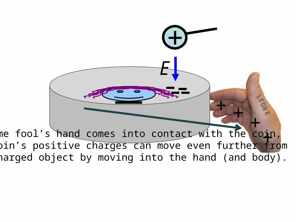
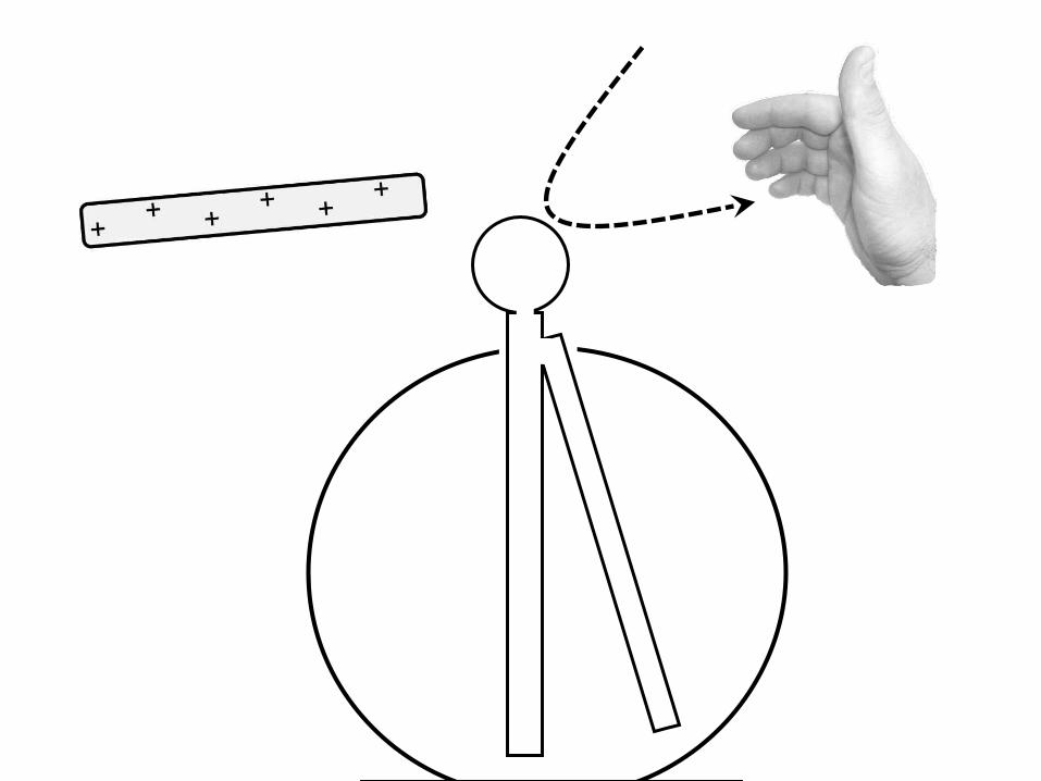
If some fool’s hand comes into contact with the coin, the coin’s positive charges can move even further fromthe charged object by moving into the hand (and body).
E
++
++

L EON
E
+- ---
++
++
+
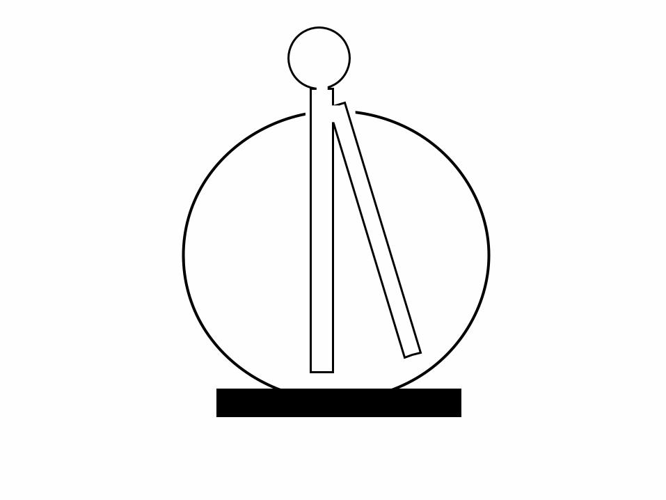
- ---
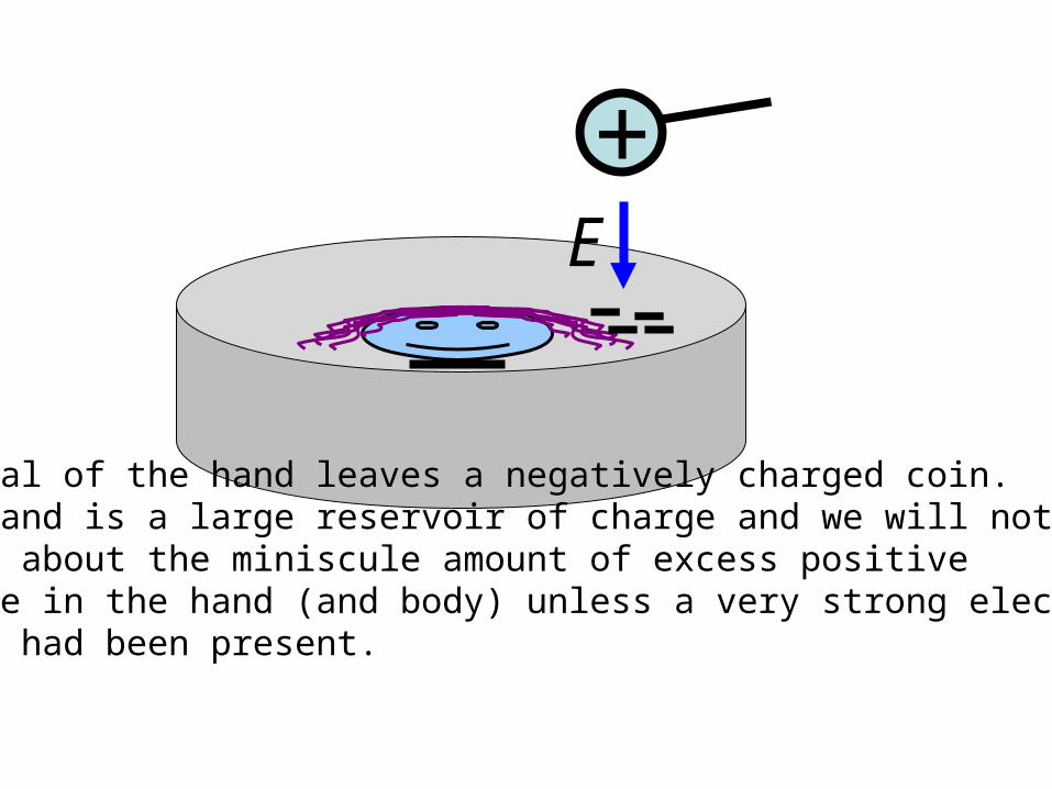
Removal of the hand leaves a negatively charged coin.The hand is a large reservoir of charge and we will not worry about the miniscule amount of excess positivecharge in the hand (and body) unless a very strong electricfield had been present.
E


+
- ---
E
In presence of positively charged object. Positively charged object removed.
?

1.5 V
1.5 V
B. C. D.
1.5 V1.5 VV1.5 V
V+
-
+
-V
+
-V

6.0 V
b
4.5 V
4.5 V
4.5 V
A. B.
6.0 V
B.A.
6.0 V

6.0 Va
b c
d
4.5 V
4.5 V
4.5 V
A. B.
7.5 V
4.5 V
B.A.
7.5 V
4.5 V

6.0 Va
b c
d
4.5 V
4.5 V
4.5 V
A. B.
7.5 V
4.5 V
B.A.
7.5 V
4.5 V

pith ball(conductor)
+Initial attraction
+repulsion after touching

metallicenclosure
solid metallicbar with round end
very thin stripof pure gold

+
+
+
+
++
+
+
+

+__
+
+
_
+
_
+
_
+
_
+
_
+
_
+
_
_
+
_
+
_
+
_
+
_
+
_
_

BA
TT
ER
Y
+
BA
TT
ER
Y
+

R VsourceRVsource
R
A. B.

BA
TT
ER
Y
+
BA
TT
ER
Y
+
BA
TT
ER
Y
+
BA
TT
ER
Y
+
V
1.5
0
3.0
4.5
6.0


-----
-- -
-+ +
++++-----
-- -
-
wal
lba
lloon
stic
ks
to w
all

+
- ---
E
+++ +

R
Vsource
R
R

+ _
_point of
intersection

+ _
_ point of intersectioncan’t happen
+
-
-
+
- +
A B C

R2
V
Requivalent

R1 R2
V

1 W 1 W
1 W 1 W

1 2
9 V
RA
4

10 V R1= 1
R2=4
I2=? V2=?
I1=? V1=?IBattery=?

12 V R1= 5
R2=1
I2=? V2=?
I1=? V1=?IBattery=?
RTotal= ?

R1
R2
10 V

9 V R1= 1 R2= 2
R3=4
I3=? V3=?
I1=? V1=? I2=? V2=?IBattery=?

R1= 8 R2= 8
R4=2 I4=? V4=?
I1=? V1=? I2=? V2=?
R3=2 I3=? V3=?
Rtotal = 5 ohmsIbattery = 2 amps
V1 = V2 = 8 voltsI1 = I2 = 1 amp
V3 = V4 = 2 voltsI3 = I4 = 1 amp
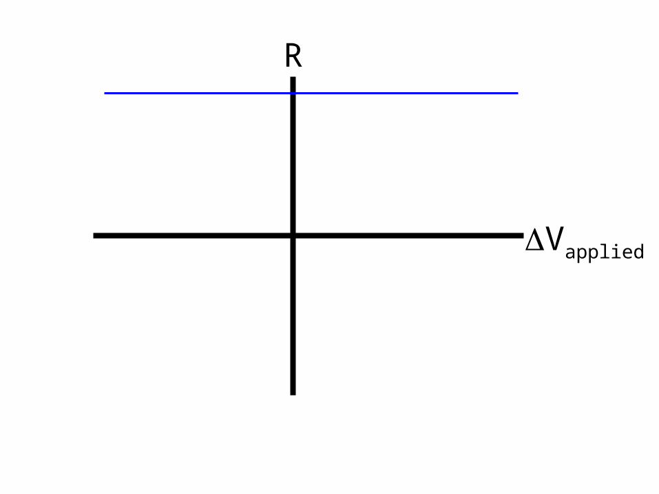
R
Vapplied

I
Vapplied

V
100 Wa b c200 W
V200 W
a
c
b
100 W d
e f

V200 W
a
c
b
100 W d
e f

R

200
100
red 1
black 2 red 2
+
-
black 1

t
V(t)
5
0
-5Dt

I
Vapplied

R1= 8 I1=? V1=?
R2=1 Requivalent = ?Ibattery = ?
V1 = ? I1 = ?
V2 = ? I2 = ?
I2=? V2=?
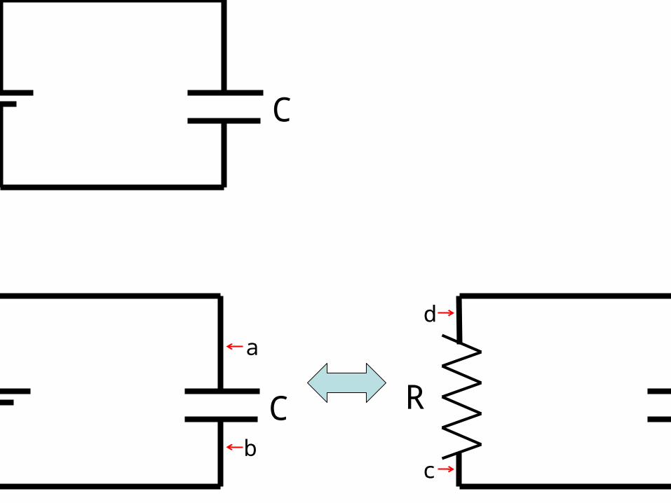
C
Cb
a
R
d
c
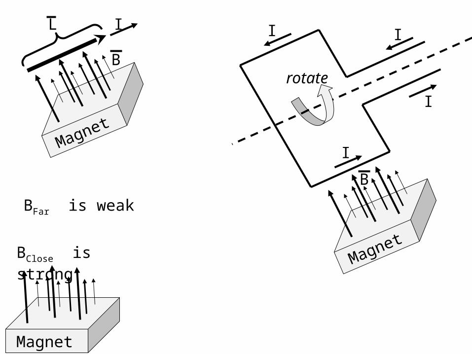
Magnet
BClose is strong
BFar is weak
Magnet
B
IL
Magnet
B
rotate
I I
I
I

I
I
I
DV

N solenoid loops enclosed in the Amperian loop, each with current I.
n is “loop density” N/L of solenoid.
BIN
Am
peria
n lo
op
L
loop Amperianby enclosed total
loopAmperian
whole
IsdB o
Ampere’s Law:
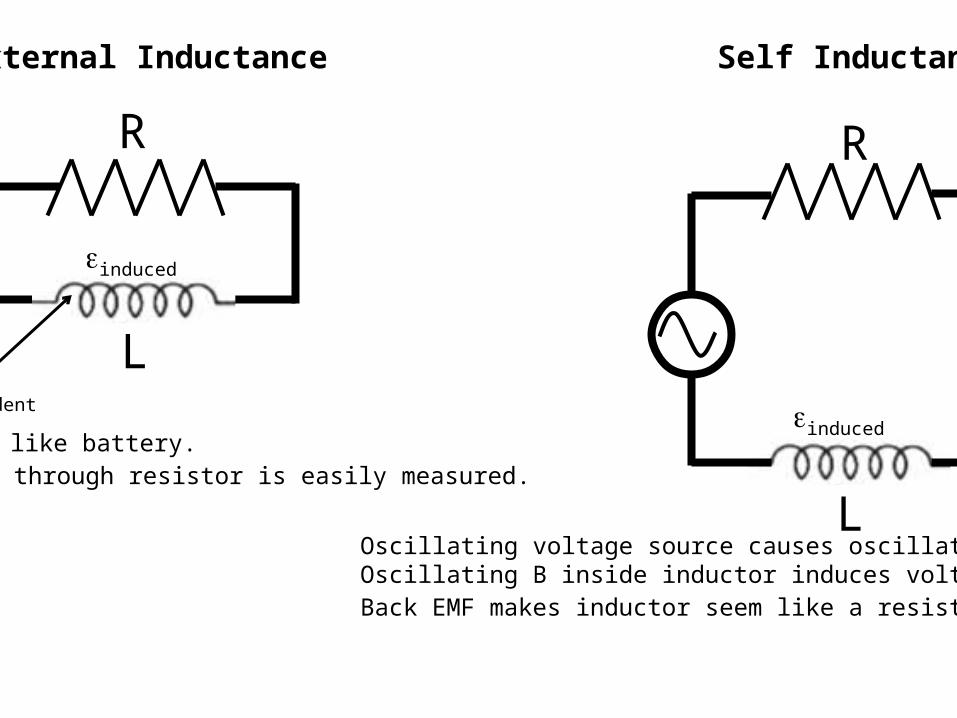
R
LBincident
einduced by B acts like battery.Current flowing through resistor is easily measured.
einduced
External Inductance
R
L
einduced
Oscillating voltage source causes oscillating B inside inductor.Oscillating B inside inductor induces voltage einduced (back EMF).Back EMF makes inductor seem like a resistor to the voltage source.
Self Inductance

R
LBincident
An oscillating external B causes an induced voltage einduced across the inductor.
einduced
External Inductance
R
L
einduced
Oscillating voltage source causes oscillating B inside inductor which induces a voltage einduced across the inductor.
Self Inductance

R
L
Self Inductance:

I
I
I
DC Power Supply+ -
brushes
Magnet
B

I
N
S
S
N

II
a
y
z
{outward}
xB ˆ [T] 3o

y
z
x

V(t)
VL
VR
VS

V(t)
V?V?
VR

V(t)
VL
VC
VR

V(t)
VC
VR
VS

V(t)
V?
VR
V?

V(t)
VL
VC
VR
VS

V(t)
VLVC
VR
VS
t

R [ohm]
C [farad]Vsource
L [henry]

Vs (t) +
-0
Vs (t) Vs (t)-VR(t)
Vs (t)-VR(t)
Vs (t)-VR(t)-VC(t)
Vs (t)-VR(t)-VC(t)Vs (t)-VR(t)-VC(t)- VL(t)=0
+Q
-Q
VS VC
+
+
+
-
-
-
VR
VL
I(t)

t
V(t)

[V]
[t]

[V]
[t]

[V]
[t]

Pulses let through by the diode move speaker withfrequency of desired audio wave.
Quantum mechanical turn-on voltage of diode.
Modulate Wave Transmitted by Diode to Speaker
[V]0

ANT
GND
A
B
PRIMARYSOLENOID
SECONDARYSOLENOID

ANT
GND
A
B
PRIMARYSOLENOID
SECONDARYSOLENOID
secondary circuit
Lsec

ANT
GND
A
B
PRIMARYSOLENOID
SECONDARYSOLENOID
secondary circuitLsec/2

Diode
A
B
TUNER
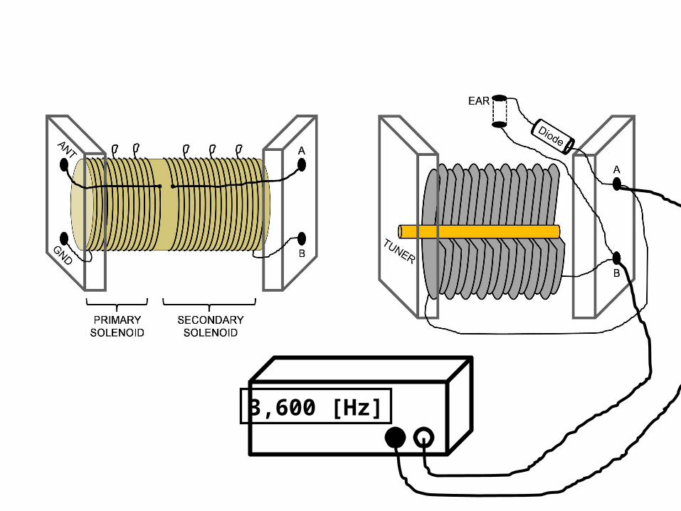
3,600 [Hz]

envelope [Hz]
carrier [Hz]
RF Modulator
RFout
lowin
CH2
CH1
modulated

carrier [Hz]
RF Modulator
RFout
lowin CH
1modulated


CH1
modulated
antenna
ground

Iamplitude
fdrive
fresonance
Iamplitude
fdrive
fresonance
A B

9 V R1= 1 R2= 2
R4=4
I4=? V4=?
I1=? V1=? I2=? V2=?IBattery=?
Requivalent=?

BATTERY+
cd

BATTERY+ +
BTotal charge +Q & -Q Total charge +Q & -Q
+ + + + + + + + + + +
+ + + + + + + +
+ + +
+ + ++ + +
- - - - -
- - - - -
- - - - - - - -
- - - - - - - -
(-Q/2)
(-Q/2)
(+Q/2)
(+Q/2)

R1
VS
S1
R2
CS2
R1 = 1x10⁶ [W]R2 = 1x10⁵ [W]C = 1x10⁻⁵ [F]Vs = 10 [V]

Thumb shows direction of magnetic field.
B
Wrap fingersin direction ofcurrent.
q
If charge q is negative,reverse B-field direction.

B
I
I
Thumb shows direction of magnetic field.

BA
TT
ER
Y
+
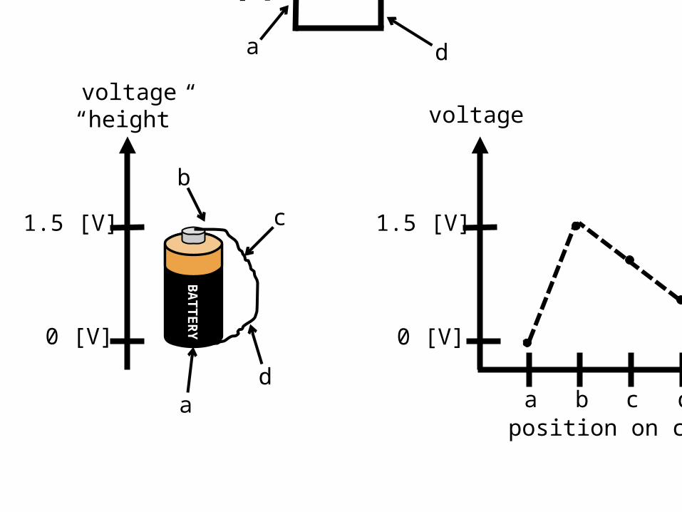
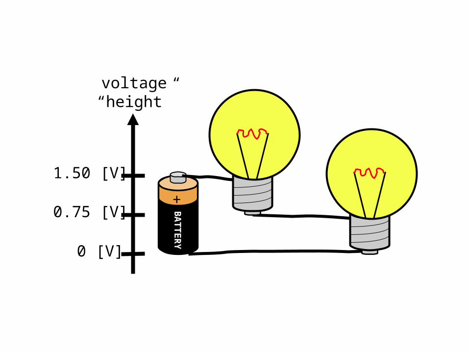
voltage“height”
1.5 [V]
0 [V] DV
= +
1.5
[V] D
V=
-1.5 [V
]

BA
TT
ER
Y
+
voltage“height”
1.5 [V]
0 [V]
BA
TT
ER
Y
voltage“height”
1.5 [V]
0 [V]
voltage
1.5 [V]
0 [V]
position on circuita b c d
1.5 [V]
a d
ad
c
b

BA
TT
ER
Y
+
voltage“height”
a
b c
de
voltage
1.5 [V]
0 [V]
position on circuit
a b c d e a

1.5 [V]1.5 [V] RBULB
a
bc
d
e

BA
TT
ER
Y
+
voltage“height”
1.50 [V]
0 [V]
a
b
c
0.75 [V]
BA
TT
ER
Y
+
voltage“height”
1.50 [V]
0 [V]
0.75 [V]

voltage
1.50 [V]
0 [V]
position on circuita b c
0.75 [V]
a
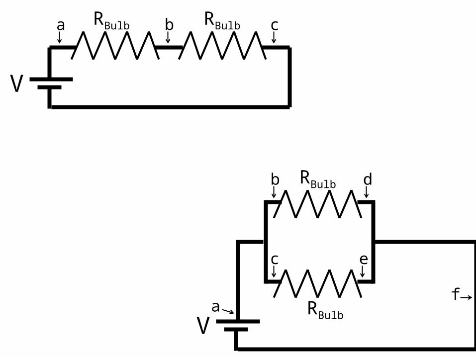
V
RBulba b cRBulb
VRBulb
a
b
f
RBulb d
c e

a
voltage“height”
1.5 [V]
0 [V]B
AT
TE
RY
+
b c
d f e

voltage
1.50 [V]
0 [V]
position on circuitf d b
0.75 [V]
a c e f aa

display
settings
+ positive terminal for high current measurements (has large fuse)
- negative terminal or “ground”
+ positive terminal

Voltage
VDC
BA
TT
ER
Y
+

? amps
BA
TT
ER
Y
+ BA
TT
ER
Y
+
mA
A B

Amperes
mA
R
BA
TT
ER
Y
+

Amperes
mA
A
R
BA
TT
ER
Y
+

Ohms ()
R

3 V
b
c
dB
AT
TE
RY
+
BA
TT
ER
Yc d
1.5 [V]
0 [V]
3 V
a b
c
d
BA
TT
ER
Y
+
BA
TT
ER
Y
+a b
c
1.5 [V]
3.0 [V]

Vamp=3 V
330
CH1 CH2
red1
red2
bottomground
x-ymode

• 30 V• Ground• 1000 V• 2000 V• 3000 V
constantvoltage ---
--
ground
--
-
---
-- -
-
-
-
-
-
ground

• 30 V• Ground• 1000 V• 2000 V• 3000 V
constantvoltage
chargeseparation
ground

+++++- ---
--
-+++++
+++++
- ---
- --
+
+
++
--
-
-
--
- +
+
evenlyarranged
clusteredpositive
clusterednegative

Real
Imaginary
V R
wtV
L
VCVS
fshift+p

Real
Imaginary
VR
V L
V C

Im{V(t)}
Re{V(t)}
Real
Imaginary
V 0
wt
V(t)=V0eiwt rotates around the complex plane in time.

Voltage
VL
VC
VR
VS

R [ohm]
C [farad]
L [henry]
R [ohm]Vsource
L [henry]
THEORY REALITY

N S

x
A B C D E

x [cm]
10 [V] 8 6 4 2 0
0 2 4 6 8 10

x [cm]
10 8 6 4 2 0 [V]
0 2 4 6 8 10
A B

N solenoid loops enclosed in the Amperian loop, each with current I.
n is “loop density” N/L of solenoid.
BIN
Am
peria
n lo
op
L
loop Amperianby enclosed total
loopAmperian
whole
IsdB o
Ampere’s Law: