TUNA HANDLING REFRIGERATION - SWFSC Home Page - SWFSC
162
Transcript of TUNA HANDLING REFRIGERATION - SWFSC Home Page - SWFSC


NOAA Technical Memorandum NMFS
The National Oceanic and Atmospheric Administration (NOAA), organized in 1970, has evolved into an agency which establishes national policies and manages and conserves our oceanic, coastal, and atmospheric resources. An organizational element within NOAA, the Office of Fisheries is responsible for fisheries policy and the direction of the National Marine Fisheries Service (NMFS).
In addition to its formal publications, the NMFS uses the NOAA Technical Memorandum series to issue informal scientific and technical publications when complete formal review and editorial processing are not appropriate or feasible. Documents within this series, however, reflect sound professional work and may be referenced in the formal scientific and technical literature.
This manual was developed and prepared by Living Marine Resources, Inc. in cooperation with the United States tuna industry and the United States Department of Commerce, National Oceanic and Atmospheric Admini- stration, National Marine Fisheries Service, under Saltonstall-Kennedy Act Grant NA84AA-H-SK092.
The Ammonia Safety information in Appendix R was reprinted, with revis ions, by permission of Cambpell Industries, San Diego, California.

NOAA Technical Memorandum NMFS
This TM Sertes IS used lor docurnentailon and timely cornrnunicatlon of prellrnmary results. mterirn reports, or Specla1 Purpose Information. and have not received complete formal review. editorial control. or detailed editing
-- c i*
AUGUST 1985 P 8 o., ___
qQru= '@@
TUNA HANDLING and REFRIGERATION on
PURSE SEINERS
Frank D. Burns Living Marine Resources, Inc.
7 169 Construction Court San Diego, California 92 12 1
NOAA-TM-NMFS-SWR- 01 1
U.S. DEPARTMENT OF C O M M E R C E Malcolm Baldrige. Secre tary National Oceanic and Atmospheric Administration Anthony J. Calio, Administrator
National Marine Fisheries Service William G. Gordon. Assistant Administrator for Fisheries

Table of Contents
CHAPTER PAGE
I INTRODUCTION 1-1
I1 REFRIGERATION SYSTEM ON A TUNA SEINER
VESSEL LAYOUT BRINE TRANSFER SYSTEM REFRIGERATION SYSTEM COMPONENTS Expansion Valves Shut-of f Valves Coils Suction Headers and Manifolds Back Pressure Regulator Suction Accumulator Safety Relief Valves Ammonia Compressors Oil Separator Check Valve Oil Trap Condenser Receiver Pressure Gauges Temperature Sensors
I11 OPERATION OF A REFRIGERATION SYSTEM
ROUTINE MAINTENANCE ADJUSTING AMMONIA FLOW SUCTION PRESSURE DISCHARGE PRESSURE USE OF SUCTION HEADERS OPERATION DURING FISH HANDLING Chilling Sea Water and Brine Chilling the Fish Freezing the Fish Drying the Wells Preparing to Unload
IV TUNA-HANDLING PROCEDURES
PREPARATION FOR STORAGE Cleaning the Wells Preparing the Brine Characteristics of Brine Measuring Brine Salinity Sequence of Well Loading
CATCHING THE FISH
11-1
1 2 5 5 11 11 14 14 18 20 22 26
28 28 32 34 34
28
111-1
1 1 3 6 6 8 9 11 11 12 12
IV-1
i

Table of Contents (continued)
CHAPTER
STORAGE IN RSW STORAGE IN BRINE PACKING THE WELLS BRINING THE WELLS FREEZING THE FISH DRYING THE WELLS UNLOADING THE FISH
V TUNA QUALITY CHANGES
GENERAL DESCRIPTION BIOLOGICAL EFFECTS Histamine Honey comb Off-Colors
Salt Penetration Protein Denaturation Drip Loss Color Change Oxidative Rancidity
EFFECTS OF FREEZING
EFFECTS OF HANDLING CONTAMINAT ION Fuel Oil Ammonia Metal Stain
VI QUALITY EVALUATION
ORGANOLEPTIC TESTS CHEMICAL TESTS
VI1 THE EFFECT OF TUNA QUALITY ON VALUE
VI11 SUMMARY
GENERAL PROCEDURES REFRIGERATION SYSTEM OPERAT I ON PREPARATION STOWING PACKING BRINING DRYING UNLOADING HANDLING FISH FROM LONG SETS
PAGE
10 14 17 21 24 26 3 3
V-1
1 1 2 5 7 8 8 11 11 11 1 2 12 1 3 1 3 14 14
VI-1
1 1
VII-1
VIII-1
.. ll

Table of Contents (continued)
APPENDIX PAGE
A FUNDAMENTALS OF REFRIGERATION A- 1
HEAT 1 TEMPERATURE 1 SPECIFIC HEAT 1 LATENT HEAT 4 PRES SURE 5 INTERACTION OF PRESSURE AND TEMPERATURE 8 PROPERTIES OF AMMONIA 9 SIMPLIFIED REFRIGERATED SYSTEM 9 COMPLETE REFRIGERATION SYSTEM 9 NORMAL OPERATING CONDITIONS ON A TUNA SEINER 15
B AMMONIA SAFETY INFORMATION
WARNING PROPERTIES FIRE AND EXPLOSION HAZARDS HEALTH HAZARDS Local Effects Chronic Toxicity
SAFETY EQUIPMENT Eye Protection Respiratory Protection
Contact with Skin and Mucous Membranes Contact with Eyes Taken Internally Nose and Throat Inhalation Asphyxiation First Aid Supplies
Leak Detection
FIRST AID
ACTION IN THE EVENT OF A LEAK
C SAMPLE WELL-HANDLING FORM
D ADJUSTING BRINE SALINITY
E FABRICATION AND USE OF THERMOCOUPLES
PROTECTING THE TEMPERATURE INDICATOR FABRICATION OF THERMOCOUPLES USE OF THERMOCOUPLES CALIBRATION OF THE SYSTEM EQUIPMENT LIST
LITERATURE CITED
B-1
1 1 2 2 2 4 4 4 5 6 6 7 7 7 8 9 9 9
c-1
D-1
E-1
1 1 3 6 6
LC-1
... Il l

List of Figures
FIGURE
2 - 1 2-2 2-3 2-4 2-5 2-6 2-7 2-8 2-9 2-10 2 -11 2-12 2-13 2-14 2-15
3 - 1
3-2
4-1 4-2
4-3
4-4
4-5
4 -6
4-7
5 - 1 5-2 5-3
A-1 A-2 A-3
A-4 A-5
E-1
General Arrangement of a 1,200 Ton Purse Seiner Brine Transfer System Tuna Seiner Refrigeration System Hand Expansion Valve Automatic Expansion Valve Shut-off Valve Arrangement of Coils in Fish Well Back Pressure Regulator Ammonia Strainer Suction Accumulator Safety Relief Valve Ammonia Compressor Oil Separator Box-Type Condenser Receiver
Compressor Refrigeration Capacity and Power Required at Different Suction Pressures Compressor Refrigeration Capacity and Power Required at Different Condensing Pressures
Relationship of Freezing Point to Salinity of Brine Temperature of RSW, Brine and the Backbone of Tuna During Chilling and Freezing Temperature of Brine and the Backbone of Tuna During Chilling and Freezing Percent of Water in Fish Muscle Frozen at Various Temperatures Temperature of Brine and the Backbone of Tuna During Freezing and Storage in a Dried Well Temperature in the Interior and on the Surface of a Well During Storage of Tuna Temperature in the Interior and on the Surface of a Well During Storage of Tuna
Histamine Content of Tuna by Time Held in Sea Water Honeycomb Scores of Tuna by Time Held in Sea Water Salt Content of Tuna by Time Held in Brine
Temperature Conversion Formulas and Scale Heat Removed from Tuna During Chilling and Freezing Relationship Between Pressure and Evaporating Temperature of Ammonia Simplified Ammonia Refrigeration System Schematic Diagram of a Refrigeration System
Thermocouple Placement
iv

List of Tables
TABLE
2-1
4-1
6-1
A- 1
A-2
A- 3
B-1
Compressor Refrigeration Capacities and Power Requirements
Sodium Chloride Brine Characteristics
Organoleptic Quality Evaluation of Raw Tuna
Conversion Table
Heat Removed from One Ton of Tuna During Chilling and Freezing
Thermodynamic Properties of Ammonia
Effects of Ammonia in Air
V
Acronyms and Abbreviations
BPR
BTU
FDA
f P
GPM
m 9
PSI
PSIA
PSIG
RSW
RPM
OSAL
TMAO
USTF
Back P r e s s u r e R e g u l a t o r
B r i t i s h T h e r m a l U n i t s
Food and Drug A d m i n i s t r a t i o n
F r e e z i n g P o i n t
G a l l o n s P e r Minute
M i l i g r am
Pounds p e r Squa re I n c h
Pounds per Squa re I n c h Abso lu te
Pounds per Squa re Inch Gauge
R e f r i g e r a t e d Sea Water
R e v o l u t i o n s P e r Minute
Sa lomete r Degrees
Tr imethylamine Oxide
Un i t ed S t a t e s Tuna Foundat ion
vi

Acknowledgements
Representatives from all branches of the tuna industry have contributed to this manual. Space does not permit acknowledging all of them here, but the following deserve special recognition for their assistance in editing sections of the manuscript.
John Adsit, Quality Refrigeration Company, Inc. Jack Appelt, Quality Refrigeration Company, Inc. Dr. Jerry Babbitt, National Marine Fisheries Service Jim Boyd, Campbell Industries Anthony Burich, Chief Engineer Harold F. Cary, United States Tuna Foundation Roy Cottrell, Campbell Industries John DeBeer, Van Camp Seafood Company, Inc. Michael Dunn, Mitsubishi (MC) Foods, Inc. Lonnie Fiero, Chief Engineer 0. E. Kerns, Jr., United States Tuna Foundation Dr. Peter Lerke, National Food Processors Association Harold Medina, Fish Captain and Vessel Owner Jack Medina, Marine Engineer/Refrigeration Consultant William Melzer, Star-Kist Foods, Inc. James Micik, Van Camp Seafood Company, Inc. Dr. William Reinke, Van Camp Seafood Company, Inc. Dan Sullivan, Bumble Bee Seafoods Tim Welch, Vilter Manufacturing Corporation Bert Youngen, Pan Pacific Fisheries Staff , Living Marine Resources , Inc.
Vii

CHAPTER I I NTRO DUCT10 N
One of the p r i n c i p a l r e s p o n s i b i l i t i e s of the c h i e f e n g i n e e r
o n a t u n a v e s s e l i s t o p r e s e r v e t h e q u a l i t y o f r a w t u n a . T o
m a i n t a i n t h e q u a l i t y o f s u c h a pe r i shab le f o o d r e q u i r e s a
c o m p r e h e n s i v e k n o w l e d g e o f : r e f r i g e r a t i o n p r i n c i p l e s , t h e
c a p a b i l i t i e s o f t h e v e s s e l ' s r e f r i g e r a t i o n s y s t e m , t h e
c h a r a c t e r i s t i c s o f q u a l i t y c h a n g e s i n f i s h , a n d t h e e f f e c t s o f
on-board h a n d l i n g on t u n a q u a l i t y ; and the a b i l i t y t o apply t h i s
knowledge t o the r a p i d l y chang ing c o n d i t i o n s on t he v e s s e l d u r i n g
a f i s h i n g t r i p .
T h e pu rpose o f t h i s manual i s t w o f o l d : (1) t o describe the
v a r i o u s f i s h - h a n d l i n g t e c h n i q u e s a n d t h e o p e r a t i o n of t h e
r e f r i g e r a t i o n s y s t e m u s e d t o p r e s e r v e t u n a on modern U n i t e d
S t a t e s p u r s e s e i n e r s , a n d ( 2 ) t o i d e n t i f y t hose p r o c e d u r e s t h a t
b e s t m a i n t a i n t u n a q u a l i t y . T h e m a n u a l h a s b e e n w r i t t e n
p r i m a r i l y f o r t h e c h i e f e n g i n e e r , b u t i n c l u d e s s u f f i c i e n t
background i n f o r m a t i o n , on the f u n d a m e n t a l s o f r e f r i g e r a t i o n , t he
r e f r i g e r a t i o n s y s t e m , f i s h - h a n d l i n g t e c h n i q u e s , t h e n a t u r e o f
f i s h q u a l i t y changes , and the e v a l u a t i o n o f r a w f i s h q u a l i t y , t o
be u s e f u l t o p e o p l e i n a l l b r a n c h e s o f the t u n a i n d u s t r y .
T h e p r e s e r v a t i o n t e c h n i q u e d i s c u s s e d i s b r i n e i m m e r s i o n
f r e e z i n g . T h i s t e c h n i q u e i n v o l v e s s t o r i n g f i s h i n b r i n e (made b y
a d d i n g s a l t t o sea w a t e r ) a n d r e d u c i n g t h e t e m p e r a t u r e o f t h e
b r i n e u n t i l the f i s h ( b u t n o t the b r i n e ) a re f r o z e n . T h i s method
can s a t i s f a c t o r i l y p r e s e r v e a v e s s e l ' s catch d e s p i t e (1) the high
sea w a t e r and f i s h t e m p e r a t u r e s e n c o u n t e r e d , r a n g i n g up t o 90°F or h i g h e r , ( 2 ) the e x t r e m e v a r i a b i l i t y o f catch ra tes , w h i c h can
be i n e x c e s s of 200 t o n s per set and 1,000 t o n s per week, and ( 3 )
t h e p o s s i b l y l o n g ( f o u r m o n t h s or m o r e ) s t o r a g e t i m e . T w o
1-1

p o t e n t i a l problems a s s o c i a t e d w i t h b r i n e immers ion f r e e z i n g are
(1) e x c e s s i v e s a l t u p t a k e b y t h e f l e s h , a n d ( 2 ) u n d e s i r a b l e
c h a n g e s i n co lo r , t e x t u r e , a n d f l a v o r d u e t o slow f r e e z i n g or
p ro longed s t o r a g e i n b r i n e .
B r i n e i m m e r s i o n f r e e z i n g w a s a d o p t e d b y t he U n i t e d S t a t e s
f l e e t i n t h e l a t e 1930s, a f t e r t h e b a i t b o a t s N o r t h w e s t e r n a n d
A m e r i c a n B e a u t y d e m o n s t r a t e d t h e e f f e c t i v e n e s s o f t h i s m e t h o d .
P r i o r t o t h a t t i m e , catches w e r e h e l d i n i ce or r e f r i g e r a t e d sea
w a t e r (RSW). V e s s e l s u s i n g e i t h e r o f these s t o r a g e m e d i a c o u l d
n o t p r e s e r v e f i s h f o r m o r e t h a n a b o u t 3 0 d a y s , a n d o f t e n l a r g e
p o r t i o n s of catches w e r e r e j e c t e d for canning . Despi te d r a m a t i c
c h a n g e s i n (1) t h e s i z e o f t u n a v e s s e l s , f r o m l e s s t h a n 100 t o n s t o o v e r 1 , 0 0 0 t o n s c a p a c i t y , ( 2 ) the method of f i s h i n g , f rom pole
a n d l i n e t o p u r s e s e i n e , a n d ( 3 ) t h e a r e a of o p e r a t i o n , f r o m
n e a r - s h o r e t o t h e h i g h seas , b r i n e i m m e r s i o n f r e e z i n g h a s
r e m a i n e d t h e p r e s e r v a t i o n m e t h o d o f choice among U n i t e d S t a t e s
t u n a f i s h e r m e n f o r a l m o s t 50 y e a r s .
----------- -------- ------
F a c t o r s a f f e c t i n g raw t u n a q u a l i t y d u r i n g on-board h a n d l i n g
a n d b r i n e i m m e r s i o n f r e e z i n g h a v e b e e n s t u d i e d ( a n d d a t a h a v e
been c o l l e c t e d ) i n t e r m i t t e n t l y . Much of the i n d u s t r y ' s p r e s e n t
u n d e r s t a n d i n g of t u n a p r e s e r v a t i o n i s b a s e d on t h e r e sea rch
conduc ted i n the l a t e 1930s by s c i e n t i s t s of the George W i l l i a m s
Hooper F o u n d a t i o n , U n i v e r s i t y o f C a l i f o r n i a , San F r a n c i s c o , o n
s o m e of t h e f i r s t t u n a v e s s e l s u s i n g b r i n e i m m e r s i o n f r e e z i n g .
World War I1 i n t e r r u p t e d t h i s research, b u t it w a s r e i n s t a t e d i n
t h e 1950s t h r o u g h t h e e f f o r t s of t he i n d u s t r y a n d t h e B u r e a u o f
C o m m e r c i a l F i s h e r i e s . One o f t h e n o t a b l e a c h i e v e m e n t s of t h e
i n d u s t r y - s u p p o r t e d work w a s t h e 1 9 5 9 p u b l i c a t i o n b y t h e
C a l i f o r n i a F i s h Canners A s s o c i a t i o n o f A Manual of R e f r i g e r a t i o n
Practice -- f o r Tuna C l ippe r s , w r i t t e n by S. Lassen and J. Rawlings. - -- - --
1-2

During the 1960s, the government e f f o r t w a s t e r m i n a t e d and
i n d u s t r y s t u d i e s w e r e r e d u c e d a s t h e i n f l u x of new v e s s e l s a n d
b e t t e r e q u i p m e n t r e s u l t e d i n a g e n e r a l i m p r o v e m e n t i n t u n a q u a l i t y . However, as l a r g e r v e s s e l s ( w i t h l a r g e r s t o r a g e w e l l s )
w e r e a d d e d t o t h e f l e e t , t h e a m o u n t o f m a r g i n a l q u a l i t y t u n a
b e g a n t o i n c r e a s e . T h i s s i t u a t i o n , i n a d d i t i o n t o i n c r e a s i n g
c o n s u m e r demand f o r l o w - s a l t p r o d u c t s a n d t h e Food a n d Drug
A d m i n i s t r a t i o n ' s (FDA) p o l i c y t o moderate t h e l e v e l o f s a l t i n the American d i e t , caused the t u n a i n d u s t r y t o fund , t h r o u g h the
Uni t ed S t a t e s Tuna Founda t ion (USTF), a two-year research pro jec t
o n t h e f a c t o r s a f f e c t i n g f i s h q u a l i t y on t u n a s e i n e r s . T h i s
s t u d y w a s c o n d u c t e d b y L i v i n g M a r i n e R e s o u r c e s , I n c . , a n
i n d e p e n d e n t f i s h e r i e s research company, d u r i n g three commercial f i s h i n g t r i p s i n 1 9 8 2 a n d 1 9 8 3 . Each t r i p w a s o n a d i f f e r e n t
m o d e r n s u p e r s e i n e r . T h e a u t h o r c o n d u c t e d t h e a t - sea research
d u r i n g t h i s project . T h e r e s u l t s form the basis f o r t h i s manual:
however , a l l a v a i l a b l e s o u r c e s of i n f o r m a t i o n , p a r t i c u l a r l y the
e x p e r i e n c e o f c h i e f e n g i n e e r s a n d p r e v i o u s s t u d i e s o n t u n a
v e s s e l s , w e r e c o n s u l t e d . T h e f i n a l r e p o r t o f t h e USTF s t u d y i s
l i s t e d u n d e r P a t t e r s o n a n d B u r n s , 1 9 8 4 i n t h e L i t e r a t u r e C i t e d
s e c t i o n o f t h i s manual , and c o n t a i n s an e x t e n s i v e b i b l i o g r a p h y .
T h e manual i s d i v i d e d i n t o s e p a r a t e chapters: however , much
o f t h e i n f o r m a t i o n i s i n t e r - r e l a t e d , a n d t h e r e f o r e a d e t a i l e d
t a b l e of c o n t e n t s has b e e n i n c l u d e d . C o n s u l t i n g t h e t a b l e o f
c o n t e n t s w i l l e n a b l e the r e a d e r t o f o l l o w a p a r t i c u l a r s u b j e c t i n
t h e t e x t .
1-3

CHAPTER I I REFRIGERATION SYSTEM ON A TUNA SEINER
VESSEL LAYOUT
T h e Uni ted S t a t e s f l e e t of t una p u r s e s e i n e r s i n c l u d e s
v e s s e l s w i t h a v a r i e t y of f i sh-car ry ing c a p a c i t i e s , designed by
d i f f e r e n t nava l a r c h i t e c t s and b u i l t by v a r i o u s s h i p y a r d s .
However, t hese ves se l s ca r ry s i m i l a r equipment, and many design
s i m i l a r i t i e s h a v e e v o l v e d o v e r t h e y e a r s . T h u s , s i m i l a r
procedures a r e followed i n operat ing t h e i r r e f r i g e r a t i o n systems.
Figure 2-1 ( t h e fold-out) shows t h e arrangement of equipment
on t h e engine-room deck and main deck ( a l s o c a l l e d t h e ' 'wet
deck") of a modern purse se ine r .
Purse s e i n e r s b u i l t i n the e a r l y 1980s have a s t e e l h u l l , an
aluminum p i l o t house, a m i d o r a f t placement of t h e main engine,
an o v e r a l l l e n g t h of abou t 2 2 5 f e e t , a 40 - foo t beam, and a 19-
f o o t d r a f t . Most have a r a t e d t u n a c a r r y i n g c a p a c i t y of 1 , 2 0 0
s h o r t t o n s . The f i s h a r e h e l d i n 1 5 t o 19 r e f r i g e r a t e d w e l l s
arranged i n p a i r s , one p o r t and one s ta rboard , w i t h t h e exception
of a s i n g l e w e l l i n t h e bow. I n mid-engine v e s s e l s t h e fo rward
p a i r s of w e l l s a r e separated by a passageway c a l l e d t h e " se rv ice
a l l e y . " Between t h e a f t p a i r s of w e l l s i s t h e " s h a f t a l l e y , "
through which r u n s t h e p r o p e l l e r s h a f t . O n af t -engine boa ts t h e
pas sage between t h e p a i r s of w e l l s i s c a l l e d t h e " p i p e a l l e y . "
The t e rm p i p e a l l e y i s u s e d i n t h e r ema inde r of t h i s manual
(Figure 2-1 shows an af t -engine vesse l ) .
The f i s h w e l l s range i n capac i ty from about 40 tons t o over
100 t o n s . A l l s i d e s of t h e w e l l s a r e i n s u l a t e d w i t h s i x i n c h e s
o f f o a m - i n - p l a c e u r e t h a n e i n s u l a t i o n and a r e l i n e d w i t h
11-1

evaporation c o i l s . I n most we l l s t h e r e a r e two sepa ra t e "banks"
of c o i l s s e r v i n g d i f f e r e n t p o r t i o n s of t h e w e l l . The un load ing
door i s mounted n e a r t h e lower edge of t h e bulkhead between
ad jacent wel ls .
B R I N E TRANSFER SYSTEM
The b r i n e t r a n s f e r o r c i r c u l a t i n g sys tem ( F i g u r e 2 - 2 )
c o n s i s t s of pipes , valves , and pumps used t o (1) f i l l w e l l s w i t h
s e a w a t e r , ( 2 ) t r a n s f e r s e a w a t e r o r b r i n e ' from w e l l t o w e l l ,
( 3 ) d i s c h a r g e t h e s e f l u i d s ove rboa rd , and ( 4 ) c i r c u l a t e them
w i t h i n a w e l l . T h i s s y s t e m u s u a l l y i n c l u d e s (1) t w o
i n t e r c o n n e c t e d s e t s of p i p e s , one 4 i n c h e s and one 6 i n c h e s i n
diameter , ( 2 ) one c e n t r i f u g a l ( i m p e l l e r ) pump w i t h a 450-gallon
p e r minute ( G P M ) c a p a c i t y , c a l l e d a b r i n e c i r c u l a t i n g pump, a t
each w e l l , ( 3 ) two chambers i n the h u l l c a l l e d sea ches t s w h i c h
a l l o w s e a w a t e r t o e n t e r t h e s y s t e m , ( 4 ) t w o 1 , 0 0 0 G P M
c e n t r i f u g a l b r i n e t r a n s f e r pumps, one connec ted t o each s e a
c h e s t , and ( 5 ) t h e b u t t e r f l y v a l v e s used t o c o n t r o l b r i n e
movement th rough t h i s sys tem. I n a d d i t i o n , c o n n e c t i o n s e x i s t
t h a t ca r ry b r i n e t o t h e f i s h chutes and t o t h e b r i n e replenishing
o r t ranssh ipping l i n e s .
The b r i n e t r a n s f e r system i s remarkably f l e x i b l e . O n most
v e s s e l s b r i n e movement can u s u a l l y be accompl ished w i t h one of
severa l d i f f e r e n t pumps passing t h e b r i n e through e i t h e r a 4-inch
o r a 6-inch l i n e . Brine can flow through non-operating pumps i n
e i t h e r d i r e c t i o n and through p a r t i a l l y opened b u t t e r f l y valves i n two d i r e c t i o n s s i m u l t a n e o u s l y : t h u s t h e sys tem c o n t i n u e s t o
1. Throughout the manual t h e term b r i n e r e f e r s only t o sea water
t o which s a l t h a s been added. Although t h i s usage i s n o t
t e c h n i c a l l y c o r r e c t ( s e a w a t e r i s a b r i n e ) , it i s s t a n d a r d
p r a c t i c e on a tuna se ine r .
11-2


4 '*
7
H kl
Figure 2-2. Brine Transfer System
11-3
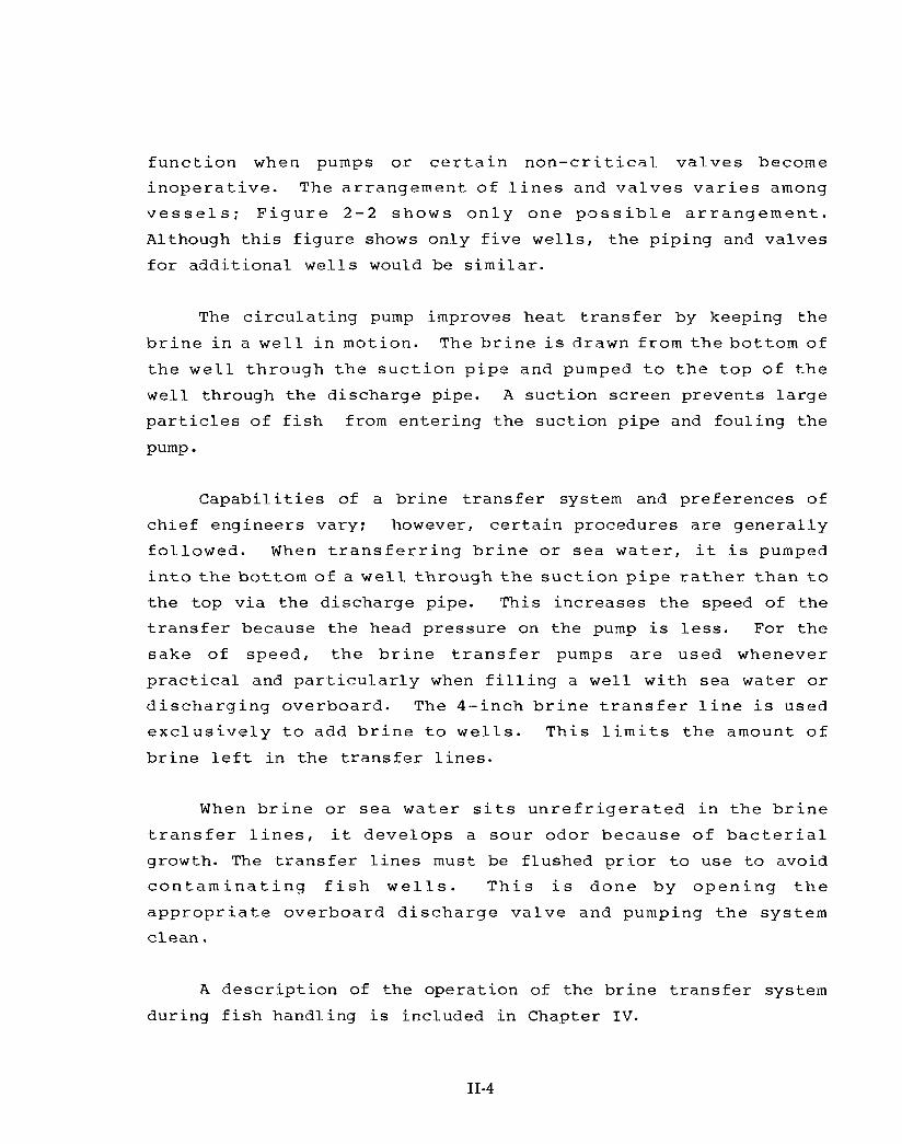
f u n c t i o n when pumps o r c e r t a i n n o n - c r i t i c a l v a l v e s become i n o p e r a t i v e . The a r r angemen t of l i n e s and v a l v e s v a r i e s among
v e s s e l s ; F i g u r e 2 - 2 shows o n l y one p o s s i b l e a r r a n g e m e n t .
Although t h i s f i g u r e shows only f i v e we l l s , t h e piping and valves
f o r add i t iona l we l l s would be s i m i l a r .
The c i r c u l a t i n g pump improves hea t t r a n s f e r by keeping t h e
b r i n e i n a w e l l i n motion. The b r i n e i s drawn from t h e bot tom of
t h e w e l l t h rough t h e s u c t i o n p i p e and pumped t o t h e t o p of t h e
wel l through t h e discharge pipe. A suc t ion screen prevents l a r g e
p a r t i c l e s of f i s h from en te r ing t h e suc t ion pipe and foul ing t h e
Pump
C a p a b i l i t i e s of a b r i n e t r a n s f e r system and preferences of
chief engineers vary; however, c e r t a i n procedures a r e gene ra l ly
f o l l o w e d . When t r a n s f e r r i n g b r i n e o r s e a w a t e r , i t i s pumped
i n t o t h e bot tom of a w e l l t h rough t h e s u c t i o n p i p e r a t h e r t h a n t o
t h e top v i a the discharge pipe. This increases t h e speed of t he
t r a n s f e r because t h e head pressure on t h e pump i s l e s s . For t h e
sake of speed , t h e b r i n e t r a n s f e r pumps a r e used whenever
p r a c t i c a l and p a r t i c u l a r l y when f i l l i n g a wel l with sea water o r
d i s c h a r g i n g overboard . The 4- inch b r i n e t r a n s f e r l i n e i s used
e x c l u s i v e l y t o add b r i n e t o w e l l s . T h i s l i m i t s t h e amount of
b r i n e l e f t i n t h e t r a n s f e r l i n e s .
When b r i n e o r s e a w a t e r s i t s u n r e f r i g e r a t e d i n t h e b r i n e
t r a n s f e r l i n e s , it deve lops a s o u r odor because of b a c t e r i a l
growth. The t r a n s f e r l i n e s m u s t be flushed p r i o r t o use t o avoid
c o n t a m i n a t i n g f i s h w e l l s . T h i s i s done by o p e n i n g t h e
a p p r o p r i a t e overboard d i s c h a r g e v a l v e and pumping t h e sys tem
c l ean .
A d e s c r i p t i o n of t he operat ion of the b r i n e t r a n s f e r system
during f i s h handling i s included i n Chapter I V .
11-4

REFRIGERATION SYSTEM COMPONENTS
A d i a g r a m o f a t u n a v e s s e l r e f r i g e r a t i o n s y s t e m i s shown i n
F i g u r e 2-3. T h e m a n i f o l d s , v a l v e s , a n d p i p i n g t h a t g i v e t h i s
system f l e x i b i l i t y a re n o t shown i n t h e f i g u r e , b u t a r e d e s c r i b e d
b e l o w . Due t o v a r i a t i o n among v e s s e l s , the e x a c t s p e c i f i c a t i o n s
o f equ ipmen t and many o f the s p e c i f i c d i r e c t i o n s f o r m a i n t e n a n c e
and o p e r a t i o n a re n o t p r e s e n t e d . This i n f o r m a t i o n i s a v a i l a b l e
i n t h e m a n u f a c t u r e r s ' b r o c h u r e s a n d m a n u a l s , w h i c h s h o u l d be
c a r r i e d on b o a r d the v e s s e l .
Expans ion V a l v e s
Expans ion v a l v e s c o n t r o l the f l o w o f l i q u i d ammonia t o the
c o i l s , a n d s e p a r a t e t h e h i g h p r e s s u r e s i d e o f t h e r e f r i g e r a t i o n
s y s t e m f r o m t h e l o w p r e s s u r e s i d e . Each b a n k of c o i l s i s
e q u i p p e d w i t h o n e h a n d e x p a n s i o n v a l v e a n d o n e a u t o m a t i c
e x p a n s i o n v a l v e , c o n n e c t e d w i t h p i p i n g a n d s h u t - o f f v a l v e s t o
a l l o w e i the r one or both t o be used.
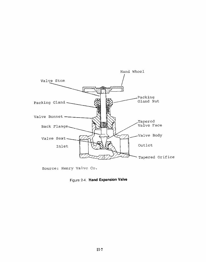
Hand Expans ion Valves . T h e f l o w o f ammonia t h r o u g h a hand
e x p a n s i o n v a l v e ( F i g u r e 2-4) i s c o n t r o l l e d b y r a i s i n g or l o w e r i n g
t he t a p e r e d v a l v e f a c e i n t o or o u t o f the t a p e r e d o r i f i c e i n the
v a l v e seat . T h e ma tch ing tapers and p o l i s h e d m e t a l s u r f a c e s o f
t h e v a l v e f a c e a n d s e a t a l l o w t h e v a l v e t o s t o p t h e f l o w o f
ammonia c o m p l e t e l y o r t o a d j u s t t h e f l o w m i n u t e l y . T h e v a l v e
f a c e i s moved b y t u r n i n g t h e h a n d w h e e l w h i c h moves t h e v a l v e
s t e m a l o n g t h e i n t e r n a l t h r e a d i n g i n t h e v a l v e b o n n e t . T h e
b o n n e t c o n t a i n s t h e p a c k i n g c h a m b e r a n d p a c k i n g t o p r e v e n t
ammonia from l e a k i n g around the v a l v e s t e m , and c o n t a i n s e x t e r n a l
t h r e a d s f o r s e c u r i n g and t i g h t e n i n g the pack ing g l a n d n u t .
Hand e x p a n s i o n v a l v e s are manufac tu red i n d i f f e r e n t s i z e s ,
w i t h t h e i n l e t a n d o u t l e t p o r t s e i t h e r i n - l i n e ( g l o b e t y p e ) o r
11-5

t -I-
+ < ACCUMULATOR
rPUUG€ VALVE I1 bi
~~
Figure 2-3. Tuna Seiner Refrigeration System
11-6
Hand Wheel
Valve Stem I
Packing Gland
Valve Bonnet --
Back Flange.
,Valve Body Valve Seat
if ice
Source: Henry Valve Co.
Figure 2-4. Hand Expansion Valve
11-7

perpendicular (angle type) t o each other . The valve stem m u s t be coated occas iona l ly wi th corrosion-preventing non-stick compound,
and t h e packing gland n u t should be t ightened i f an ammonia leak
i s d e t e c t e d . The h i g h p r e s s u r e l i q u i d ammonia p a s s i n g be tween
t h e v a l v e s e a t and v a l v e f a c e produces g rooves i n b o t h s u r f a c e s
a f t e r a few years of use. When t h i s occurs t h e valve s e a t should
be r e p l a c e d i f it i s removable , o r a t e m p o r a r y r e p a i r c a n b e made
by lapping t h e two tapered sur faces .
Automat ic Expansion Valves . Automat ic expans ion v a l v e s
(F igure 2 - 5 ) a r e c a l l e d " t h e r m o s t a t i c " o r I1thermal" expans ion
v a l v e s o r s i m p l y " t h e r m o s , " ' ' t h e r m a l s , " o r " a u t o m a t i c s . " The
term ''automatic' ' i s used here.
. . . . . . . . . . . . . . . . . . . . . . . . .
The funct ion of an automatic i s t o meter t h e flow of l i q u i d
ammonia i n t o t h e c o i l s so t h e ammonia l e a v i n g t h e c o i l s i s a
s u p e r h e a t e d vapor , t h e r e b y p r e v e n t i n g l i q u i d ammonia from
r e a c h i n g t h e compresso r s . By r e spond ing t o t h e t e m p e r a t u r e of
t h e ammonia vapor l e a v i n g t h e c o i l s and t h e p r e s s u r e i n t h e
c o i l s , t h e automatic can cont ro l t h e amount of superheat. Three
f o r c e s ( F i g u r e 2-5B) govern t h e o p e r a t i o n of t h e a u t o m a t i c : (1)
t h e pressure (P1) i n t h e remote bulb and power assembly, ( 2 ) t h e
p r e s s u r e (P2) i n t h e e v a p o r a t o r c o i l s , and ( 3 ) t h e p r e s s u r e ( P 3 )
of t h e s u p e r h e a t s p r i n g . The p r e s s u r e i n t h e remote b u l b and
power assembly pushes down on t h e diaphragm and valve p in tending
t o open t h e v a l v e . Opposed t o t h i s i s t h e p r e s s u r e i n t h e c o i l s
and the force exerted by the superheated spring.
The pressure i n t h e remote b u l b and power assembly inc reases
a s t h e t e m p e r a t u r e of t h e ammonia vapor i n t h e c o i l d i s c h a r g e
l i n e ( t h e l o c a t i o n of t h e remote bulb) increases . When the vapor i s s u f f i c i e n t l y s u p e r h e a t e d , t h i s p r e s s u r e i s g r e a t e r t h a n t h e
combination of t h e pressure i n t h e c o i l and t h e force exerted by
11-8

R e m o t e B u l b
Power A s s e m b l y B u l b Tubing
V a l v e P i n
Superhea t S p r i n g
Superheat S p r i n g A d j u s t i n g Stern
I n l e t
I n l e t S t r a i n e r
A . I n t e r i o r
R e m o t e B u l b and Power A s s e m b l y P r e s s u r e
I n P r e s s u r e
O u t l e t u B . O p e r a t i o n
Source: A l c o C o n t r o l D i v i s i o n E m e r s o n E l e c t r i c C o .
Figure 2-5. Automatic Expansion Valve
11-9

t h e s u p e r h e a t s p r i n g , and t h e v a l v e opens. Converse ly , a s t h e t e m p e r a t u r e o f t h e g a s l e a v i n g t h e c o i l d e c r e a s e s ( l e s s
s u p e r h e a t ) , t h e p r e s s u r e i n t h e remote b u l b and power assembly
decreases , and t h e combined evaporator and spr ing pressure c loses
t h e valve.
The automatics normally found on tuna v e s s e l s a r e i n t e r n a l l y
e q u a l i z e d and e x t e r n a l l y a d j u s t a b l e , and a r e equipped w i t h a
removable i n l e t s t r a i n e r . An i n t e r n a l l y equalized automatic has
an i n t e r n a l p a s s a g e i n t h e power assembly th rough which t h e
e v a p o r a t o r p r e s s u r e a t t h e v a l v e i t s e l f i s e x e r t e d on t h e
u n d e r s i d e o f t h e d i a p h r a g m ( s e e P 2 i n F i g u r e 2-5B). A n
e x t e r n a l l y e q u a l i z e d v a l v e h a s a s e p a r a t e chamber on t h e
u n d e r s i d e o f t h e diaphragm t o which t h e p r e s s u r e a t t h e c o i l
d i s c h a r g e ( e v a p o r a t o r o u t l e t ) i s t r a n s m i t t e d th rough a s m a l l
p ressure equal iz ing l i n e which i s connected t o t h e c o i l near t h e
l o c a t i o n of the remote bulb.
The e x t e r n a l l y ad jus t ab le f e a t u r e a l lows t h e flow of ammonia
and t h e amount of superheat t o be con t ro l l ed without d i smant l ing
t h e v a l v e : t h e s e a l cap can be removed and t h e a d j u s t i n g stern turned. Rotating t h e stem clockwise decreases r e f r i g e r a n t flow
and i n c r e a s e s s u p e r h e a t . The i n l e t s t r a i n e r p r e v e n t s s m a l l
p a r t i c l e s from clogging t h e valve opening. The s t r a i n e r m u s t be
cleaned p e r i o d i c a l l y t o ensure a f r e e flow of ammonia.
The l o c a t i o n and mounting o f t h e remote b u l b a r e c r u c i a l .
T h e b u l b should be a t t a c h e d t o a h o r i z o n t a l s e c t i o n of t h e c o i l
j u s t a f t e r it l e a v e s t h e w e l l . The p a t h of t h e c o i l i n t h e w e l l
shou ld be t r a c e d t o e n s u r e t h a t t h e remote buLb i s on t h e same
c o i l a s t h e a u t o m a t i c . The coi l . should be c l e a n e d t h o r o u g h l y
b e f o r e t h e remote b u l b is mounted. The remote b u l b should be
i n s t a l l e d toward t h e bottom of t h e c o i l a t a p o s i t i o n of about 4
11-10

o r 8 o ' c l o c k . T h i s e n s u r e s t h a t t h e b u l b i s a f f e c t e d by l i q u i d ammonia--if t h e bulb i s placed on t h e bottom of the c o i l , o i l i n t h e pipe w i l l i n s u l a t e t h e b u l b and i n t e r f e r e wi th i t s operat ion.
The bulb and a s h o r t s ec t ion of t h e c o i l t o which it i s a t tached
should be wrapped with waterproof i n s u l a t i o n (neoprene rubber i s
commonly u s e d ) . The b u l b t u b i n g shou ld n o t be i n s t a l l e d n e a r
o t h e r c o i l s o r l o c a t i o n s where i ce b u i l d s up, s i n c e t h e c o l d
t e m p e r a t u r e s a t t h e s e s p o t s w i l l a f f e c t t h e o p e r a t i o n of t h e
automatic. Where necessary, t h e bulb tubing should be insu la ted .
Shut-of f Valves
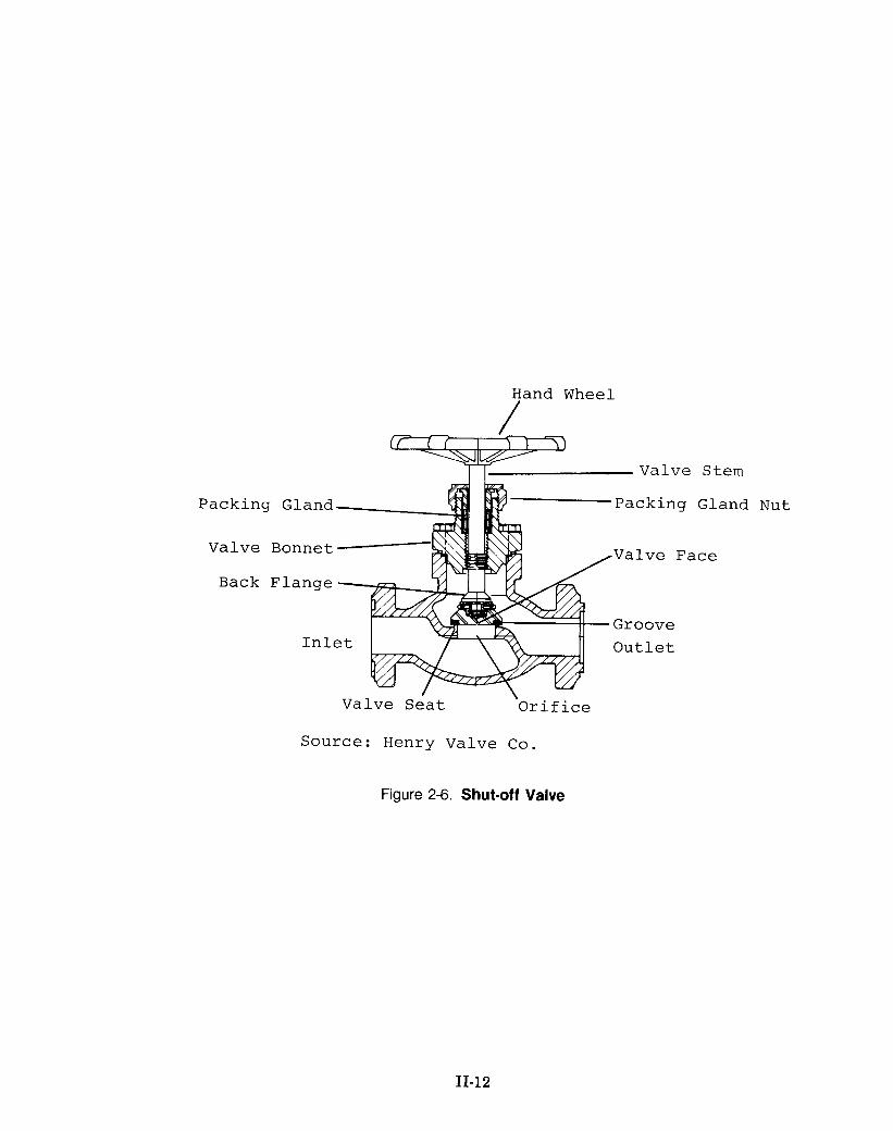
Shu t -o f f v a l v e s ( F i g u r e 2 - 6 ) , o r s t o p v a l v e s , a r e used t o
s t o p t h e f low of ammonia w i t h i n t h e r e f r i g e r a t i o n sys tem and
i s o l a t e components so r e p a i r s o r replacement can be accomplished
w i t h o u t e v a c u a t i n g ammonia from t h e e n t i r e sys tem. Shu t -o f f
v a l v e s have a f l a t f a c e w i t h a groove around t h e c i r c u m f e r e n c e .
T h i s groove i s f i l l e d w i t h l e a d which c r u s h e s s l i g h t l y a g a i n s t
t h e f l a t valve s e a t forming a sea l when t h e valve i s closed. I f
t h e v a l v e f a c e i s damaged by c l o s i n g t h e v a l v e t o o t i g h t l y , i t
can be r e p a i r e d . L ike t h e hand expans ion v a l v e s , t h e s e v a l v e s
have a back f lange t h a t f i t s aga ins t t h e s e a t i n t h e valve bonnet
when t h e valve i s f u l l y opened t o permit t he add i t ion of packing
while t h e valve i s opera t ing under pressure.
Coi l s
The coi ls a r e constructed from 1-1/4-inch diameter schedule
40 welded seam s t e e l p i p e t h a t i s h o t - d i p g a l v a n i z e d on t h e
e x t e r i o r . The pipe i s formed i n t o c o i l s so the d i s t ance between
t h e p ipes i s 6 t o 8 inches (Figure 2-7). The c o i l s a r e shaped t o
conform t o t h e bu lkheads , f l o o r , and overhead , and a r e h e l d t o
the wel l sur faces by "hangers." Wells a r e equipped w i t h one bank
11-11
Hand Wheel
/ T Valve Stem
Packing Gland Packing Gland
Valve Face Valve Bonnet __Lc
-Groove Outlet
. Valve Seat Orif ice
Source: Henry Valve Co.
Nut
Figure 2-6. Shut-off Valve
11-12

Figure 2-7. Arrangement of Coils in Fish Well
11-13

of c o i l s , c o n t a i n i n g abou t 1 , 0 0 0 f e e t of p i p e , f o r each 30 t o n s of c a r r y i n g c a p a c i t y . Most w e l l s have two banks of c o i l s , and
t h e l a r g e bow well i s equipped w i t h four. The por t ion of a wel l
s e r v e d by a s e t of c o i l s v a r i e s depending on t h e v e s s e l b u i l d e r
and d e s i g n e r , and should be r eco rded t o f a c i l i t a t e checking t h e
l o c a t i o n of t h e a u t o m a t i c ' s remote b u l b s . T h i s w i l l e n a b l e t h e
e n g i n e e r t o d e t e r m i n e whether i c e i s be ing formed by o n l y one
bank and whe the r o n e b a n k of c o i l s i s s u f f i c i e n t t o r e f r i g e r a t e a
foamed wel l (See Chapter I V ) .
Coi l s , p a r t i c u l a r l y the ones i n t h e unloading we l l s , should
be checked p e r i o d i c a l l y f o r r u s t i n g , l eaks , and damage t o prevent
f i s h s p o i l a g e and haza rdous c o n d i t i o n s from deve lop ing d u r i n g
unloading.
Suct ion Headers and Manifolds --
Most t u n a v e s s e l s have t h r e e s e t s of p i p e , t h r e e o r f o u r
i n c h e s i n d i a m e t e r , c a l l e d s u c t i o n h e a d e r s o r s u c t i o n mains ,
which ca r ry ammonia from t h e c o i l s through t h e pipe a l l e y t o t h e
compressors. The discharge from each bank of c o i l s i s connected
t o t h e suc t ion headers through a manifold equipped with a shut-
o f f v a l v e a t each heade r . By opening and c l o s i n g t h e p r o p e r
m a n i f o l d v a l v e s e a c h b a n k o f c o i l s c a n b e a t t a c h e d t o a n y s u c t i o n
header. A t t h e compressor end of t h e suc t ion headers t h e valves
i n t h e m a n i f o l d a l l o w e a c h h e a d e r t o b e c o n n e c t e d t o any
combination of compressors. The f l e x i b i l i t y of t h i s arrangement
i s not a f f ec t ed by t h e number o r pos i t ion ing of t h e accumulators
and back pressure r egu la to r ( s ) .
Back Pressure Reaulator
The back p r e s s u r e r e g u l a t o r (BPR) ( F i g u r e 2-8) i s des igned
t o prevent t h e pressure (and consequently t h e temperature) i n t h e
11-14

/--Adjusting Stem
S C
Source: Hubbell Corp.
Figure 2-8. Back Pressure Regulator
11-15

evaporator coils from falling below a set level. The BPR closes when the evaporator pressure falls.
A s shown in Figure 2-8, the pressure in the coils is held back at point "A" by contact between the main body seat and the seat disc. The internal equalizer line transmits the evaporator pressure to the sensing chamber. The pressure-adjusting spring pushes the diaphragms onto the pilot seat bead sealing port ''B."
When the evaporator pressure exceeds the force of this spring, the diaphragms are flexed opening port " B , " which allows the evaporator pressure to push on the top of the power piston. This moves the push rod and disc piston assembly down, opening the BPR
at point "A" and allowing ammonia to flow to the compressors. A decrease in the coil pressure results in the closing of port IIB."
The pressure above the power piston bleeds through port 'IC''
causing the B P R to close. The evaporator pressure setting is changed by turning the adjusting stem--usually clockwise rotation increases the pressure setting. The gauge attached to the B P R
measures the evaporator pressure.
The B P R cannot maintain a coil pressure lower than the compressor suction pressure. B P R s are primarily used to maintain a constant temperature in wells of RSW in order to prevent ice formation on the coils. They are used also to ensure stable temperatures in wells with frozen fish.
The one or two B P R s on a vessel are tied into individual suction headers with shut-off valves and bypass piping. Usually a strainer, also called a scale trap (Figure 2 - 9 ) , is installed upstream of the BPR. A strainer has a removable screen which traps particles that could interfere with the operation of the refrigeration system. The B P R s and strainer should be dismantled and cleaned once during each trip.
11-16
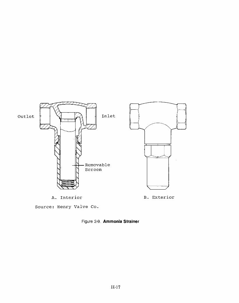
Out le t
A. I n t e r i o r
Source: Henry Valve C o .
B. Ex te r io r
Figure 2-9. Ammonia Strainer
11-17

Suction Accumulator
S u c t i o n a c c u m u l a t o r s ( F i g u r e 2 - 1 0 ) , a l s o c a l l e d
"vapor i te rs2 , ' ' a r e tanks i n s t a l l e d i n t h e suc t ion l i n e s upstream
from t h e compressors which accumulate l i q u i d ammonia and prevent
it from r e a c h i n g t h e compressors . A p u r s e s e i n e r may have one accumulator per suc t ion header o r one f o r each compressor.
Small amounts of l i q u i d ammonia en ter ing an accumulator f a l l
t o t h e bottom and eventua l ly evaporate. The vapor then flows t o
t h e compressor. The he ight of l i q u i d ammonia i n an accumulator
i s ind ica ted by a band of f r o s t t h a t forms on i t s outs ide. Most
a c c u m u l a t o r s have a l i q u i d l e v e l s e n s o r t h a t t r i g g e r s an aLarm
when t o o much l i q u i d ammonia c o l l e c t s . T h i s c o n d i t i o n i s c o r r e c t e d by opening t h e h o t g a s b o i l o u t l i n e and bubb l ing h o t
ammonia vapor from t h e compressor d i s c h a r g e l i n e th rough t h e
l i q u i d ammonia , i n c r e a s i n g i t s r a t e o f e v a p o r a t i o n . The
compressor discharge pressure should be watched c a r e f u l l y during t h i s p r o c e s s because e x c e s s i v e s u p e r h e a t may be added t o t h e
vapor en ter ing the compressor.
O i l t h a t e n t e r s an accumulator c o l l e c t s beneath the l i q u i d
ammonia, because of o i l ' s g r e a t e r densi ty . Therefore, t he bottom
of t h e band of f r o s t caused by l i q u i d ammonia i n d i c a t e s t h e l e v e l
of accumulated oil ( o i l does not cause f r o s t t o form).
O i l r educes t h e a c c u m u l a t o r ' s c a p a c i t y t o h o l d l i q u i d
ammonia; t h e r e f o r e , o i l shou ld be d r a i n e d a t l e a s t once each
t r i p , o r whenever t h e o i l l aye r i s more than s i x inches deep. O i l
can be removed by u s i n g a c l e a r hose f i r m l y a t t a c h e d t o t h e
accumulator 's o i l d ra in . The end of t h e hose should be placed i n
--- 2 . V a p o r i t e r i s a r e g i s t e r e d t r a d e m a r k o f t h e V i l t e r
Manufac tur ing Corp. The ment ion o f brand names does n o t imply
endorsement by t h e United S t a t e s Government.
11-18

\ \ ---7 I
1 I L-J
‘ I I , I ‘ I ! I ‘ I ! I ‘ I ! I
‘ I I I I I
Figure 2-1 0. Suction Accumulator
11-19

t h e bot tom of a bucke t c o n t a i n i n g s e v e r a l i n c h e s of w a t e r . Ammonia mixed w i t h t h e o i l w i l l d i s s o l v e i n t h i s w a t e r . The
shut-off valve on t h e d r a i n s h o u l d b e opened s l o w l y and c l o s e d a s
soon a s l i q u i d ammonia a p p e a r s i n t h e hose . The c o l l e c t e d o i l
should be added t o a properly vented used-oil s to rage tank.
Safe ty Rel ief Valves
Safety r e l i e f valves (Figure 2 - 1 1 ) a r e designed t o r e l i e v e
excessive and dangerous pressure from t h e r e f r i g e r a t i o n system.
They a r e g e n e r a l l y i n s t a l l e d on a c c u m u l a t o r s , condense r s , and
r e c e i v e r s . Ammonia compresso r s a r e equipped w i t h an i n t e r n a l
s a f e t y r e l i e f v a l v e . The v a l v e s a r e s e t and s e a l e d a t t h e
f a c t o r y t o open a t a s p e c i f i e d p r e s s u r e l e v e l . Those on t h e
compresso r s , condense r s , and r e c e i v e r s a r e s e t t o open a t 2 5 0
PSIG (pounds per square inch gauge) and those on t h e accumulators
open a t 150 P S I G . The number of r e l i e f v a l v e s r e q u i r e d depends
on t h e i n t e r n a l volume of a p iece of equipment. Usually only t h e
r e c e i v e r s a r e equipped w i t h more t h a n one r e l i e f v a l v e . A d u a l
r e l i e f v a l v e assembly i s connec ted t o t h e r e c e i v e r t h rough a
three-way v a l v e t h a t a l l o w s e i t h e r r e l i e f v a l v e t o be removed
when t h e system i s pressurized. During normal use t h e three-way
v a l v e i s c l o s e d so o n l y one r e l i e f v a l v e i s exposed t o t h e
pressure i n t h e system.
The d e s i g n and g e n e r a l c o n s t r u c t i o n of r e l i e f v a l v e s i s s i m i l a r t o t h a t of hand expansion and shut-off valves. One major
d i f f e r e n c e i s t h a t a heavy c o i l e d s p r i n g h o l d s t h e v a l v e f a c e
a g a i n s t t h e v a l v e s e a t u n l e s s t h e working p r e s s u r e ( s tamped on
t h e body of t h e valve) i s exceeded. When t h i s condi t ion occurs, t h e ammonia vapor e s c a p e s th rough t h e v a l v e and i s c a r r i e d
overboard t o t h e atmosphere through piping. Once a r e l i e f valve
h a s opened, it w i l l n o t r e s e a t p r o p e r l y and should be r e p l a c e d .
Temporary r e p a i r can be made by r e sea t ing t h e valve manually.
11-20

Spring
Valve Fac Valve Sea
Factory Seal
Outlet
Inlet A. Single Relief Valve
Three-way Valve ‘Three-way Valve Inlet
B. Dual Relief Valve Assembly Source: Henry Valve Co.
Figure 2-1 1. Safety Relief Valve
11-21
Ammonia Comnressors
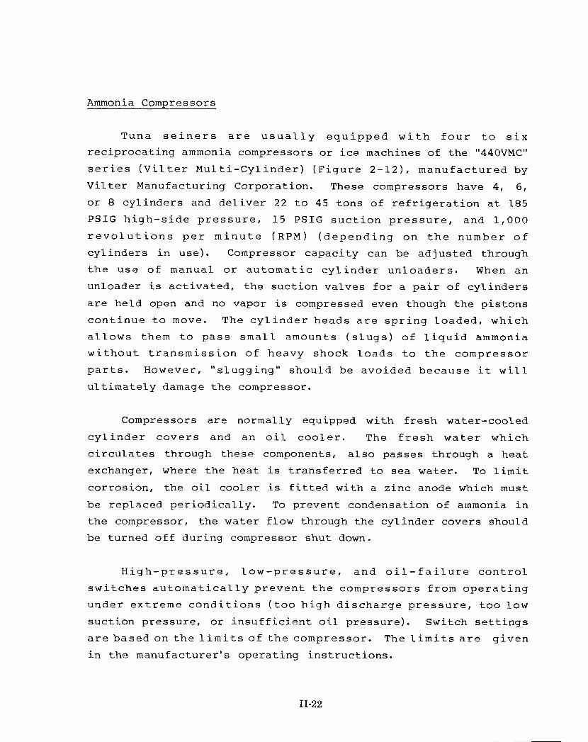
Tuna s e i n e r s a r e u s u a l l y e q u i p p e d w i t h f o u r t o s i x rec iproca t ing ammonia compressors o r i c e machines of t h e "440VMC"
s e r i e s ( V i l t e r M u l t i - C y l i n d e r ) ( F i g u r e 2 - 1 2 ) , manufac tu red by
V i l t e r Manufacturing Corporation. These compressors have 4, 6 ,
or 8 cy l inde r s and d e l i v e r 2 2 t o 45 tons of r e f r i g e r a t i o n a t 185 P S I G h i g h - s i d e p r e s s u r e , 1 5 P S I G s u c t i o n p r e s s u r e , and 1 , 0 0 0
r e v o l u t i o n s p e r m i n u t e ( R P M ) ( d e p e n d i n g on t h e number o f
cy l inde r s i n use) . Compressor capac i ty can be ad jus ted through
t h e use of manual o r a u t o m a t i c c y l i n d e r u n l o a d e r s . When an
unloader i s a c t i v a t e d , t h e suc t ion valves f o r a p a i r of cy l inde r s
a r e held open and no vapor i s compressed even though t h e p i s tons
c o n t i n u e t o move. The c y l i n d e r heads a r e s p r i n g l o a d e d , which
a l l o w s them t o p a s s s m a l l amounts ( s l u g s ) of l i q u i d ammonia w i t h o u t t r a n s m i s s i o n of heavy shock l o a d s t o t h e compressor
p a r t s . However, " s l u g g i n g " should be avoided because it w i l l
u l t i m a t e l y damage t h e compressor.
Compressors a r e normally equipped with f r e s h water-cooled
c y l i n d e r c o v e r s and an o i l c o o l e r . The f r e s h w a t e r which
c i r c u l a t e s through these components, a l s o passes through a hea t
exchanger, where t h e hea t i s t r a n s f e r r e d t o sea water. To l i m i t
cor ros ion , t h e o i l cooler i s f i t t e d with a z inc anode which m u s t
be replaced pe r iod ica l ly . To prevent condensation of ammonia i n t h e compressor, t he water flow through the cy l inder covers should
be turned o f f during compressor shut down.
H i g h - p r e s s u r e , l o w - p r e s s u r e , and o i l - f a i l u r e c o n t r o l
s w i t c h e s a u t o m a t i c a l l y p r e v e n t t h e compresso r s from o p e r a t i n g
under ex t r eme c o n d i t i o n s ( t o o h i g h d i s c h a r g e p r e s s u r e , t o o low
suc t ion pressure , o r i n s u f f i c i e n t o i l p ressure) . Switch s e t t i n g s
a r e b a s e d o n t h e l i m i t s o f t h e compressor . The l i m i t s a r e g i v e n
i n t h e manufacturer 's opera t ing i n s t r u c t i o n s .
11-22

Suct ion Pressure Gauge
-Discharge P re
I n t e r n a l R e
O i l Cooler
s s u r e
l i e f
-Flywheel
A. Ex te r io r O i l Drain/
Spring-Loaded Cylinder Head Suct ion \ Disc,harge Valve ad^:
Rol le r Main
Sha f t
O i l Level i n Crank C a s e
B . I n t e r i o r
Source: V i l t e r Manufacturing Corporation, Milwaukee, Wisconsin
Figure 2-1 2. Ammonia Compressor
11-23

Each compressor i s d r i v e n a t about 1 ,000 r e v o l u t i o n s p e r
minute by an e l e c t r i c motor a t tached t o t h e compressor flywheel w i t h a s e t of V-be l t s . Gauges a t t h e i n l e t and d i s c h a r g e show t h e s u c t i o n and d i s c h a r g e p r e s s u r e f o r each machine. The
s u g g e s t e d maximum l i m i t s f o r a c o m p r e s s o r ' s d i s c h a r g e
t e m p e r a t u r e , d i s c h a r g e p r e s s u r e , s u c t i o n p r e s s u r e , o i l
t e m p e r a t u r e , compress ion r a t i o , and so f o r t h , a r e l i s t e d i n t h e
o p e r a t i n g i n s t r u c t i o n s manual. These l i m i t s ( e x c e p t f o r t h e
compression r a t i o ) a r e not exceeded during normal opera t ions on a
tuna se ine r .
The compression r a t i o i s ca lcu la ted by d iv id ing the absolu te
d i s c h a r g e p r e s s u r e by t h e a b s o l u t e s u c t i o n p r e s s u r e . (The
r e l a t i o n s h i p between a b s o l u t e p r e s s u r e (pound p e r s q u a r e i n c h
a b s o l u t e , P S I A ) and gauge p r e s s u r e i s d i s c u s s e d i n Appendix A ) .
Since the recommended maximum compression r a t i o i s 8:1, t h e lower
l i m i t f o r t h e suc t ion pressure can be determined by d iv id ing t h e
a b s o l u t e d i s c h a r g e p r e s s u r e by 8. Thus, when t h e d i s c h a r g e
p r e s s u r e i s 199.7 P S I A (185 P S I G ) , t h e s u c t i o n p r e s s u r e shou ld
n o t f a l l below 25.0 P S I A (199 .7 /8 ) , o r 10.3 P S I G .
A s t h e compress ion r a t i o i n c r e a s e s , t h e r e f r i g e r a t i o n
capac i ty and e f f i c i e n c y of a compressor decreases (Table 2 - 1 ) and
t h e amount of s u p e r h e a t i n t h e d i s c h a r g e g a s , l o a d on t h e
b e a r i n g s , and g e n e r a l wear i n c r e a s e s . Excess ive s u p e r h e a t i n g
w i l l d e p o s i t ca rbon on t h e d i s c h a r g e v a l v e s and may damage t h e
compressor . Compressors can be o p e r a t e d a t compress ion r a t i o s
above t h e suggested maximum without producing immediate s igns of
m a l f u n c t i o n i n g . However, t h i s p r a c t i c e w i l l r e s u l t i n more
frequent r e p a i r s , breakdowns, and shortened compressor l i f e .
With proper rou t ine maintenance, a compressor should provide continuous s e r v i c e f o r a t l e a s t two years. The condi t ion of t h e
11-24

Table 2-1 . Compressor Refrigeration Capacities and Power Requirements
Condensing Pressure PSIG and Corresponding Suction 4 Cylinder 6 Cylinder 8 Cylinder
OF O F PSIG Tons BHP Tons RHP Tons BHP Temperature Temp Press a
-15c 6 . 2 1 3 . 5 3 0 . 2 2 0 . 2 4 4 . 5 2 7 . 0 5 9 . 2 -10 9 . 0 1 6 . 4 3 2 . 2 2 4 . 6 4 7 . 5 3 2 . 9 6 3 . 2 - 5 1 2 . 2 1 9 . 7 3 4 . 5 2 9 . 5 5 0 . 9 3 9 . 5 6 7 . 6
0 1 5 . 7 2 3 . 3 3 6 . 9 3 4 . 9 5 4 . 5 4 6 . 6 7 2 . 4 1 6 5 # 5 1 9 . 6 2 7 . 3 3 9 . 4 4 0 . 9 5 8 . 0 5 4 . 7 7 7 . 1 8 9 . 6 " 1 0 2 3 . 8 3 1 . 7 4 1 . 3 4 7 . 5 6 0 . 9 6 3 . 5 8 1 . 0
1 5 2 8 . 4 3 6 . 4 4 2 . 8 5 4 . 6 6 3 . 2 7 2 . 8 8 4 . 0 20 33.5 4 1 . 6 4 3 . 8 6 2 . 4 6 4 . 6 8 3 . 2 8 5 . 9 2 5 3 9 . 0 4 7 . 1 4 4 . 2 7 0 . 6 6 5 . 2 9 4 . 2 8 6 . 6 3 0 4 5 . 0 5 3 . 0 4 4 . 5 7 9 . 5 6 5 . 7 1 0 6 . 1 8 7 . 2 3 5 5 1 . 6 5 9 . 6 4 4 . 7 8 9 . 4 6 6 . 0 1 1 9 . 2 8 7 . 7
-15' 6 .2 1 3 . 2 3 1 . 4 1 9 . 8 4 6 . 5 -10 9 . 0 1 6 . 1 33.5 2 4 . 1 4 9 . 5 - 5 1 2 . 2 1 9 . 3 35.8 2 8 . 9 5 2 . 7
0 1 5 . 7 2 2 . 8 3 8 . 0 3 4 . 3 5 6 . 0 1 7 5 # 5 1 9 . 6 2 6 . 8 4 0 . 4 4 0 . 2 5 9 . 5 9 3 . 0 " 1 0 2 3 . 8 3 1 . 1 4 2 . 4 4 6 . 6 6 2 . 5
15 2 8 . 4 3 5 . 8 4 4 . 0 5 3 . 7 6 4 . 8 2 0 3 3 . 5 4 0 . 9 4 5 . 2 6 1 . 3 6 6 . 6 2 5 3 9 . 0 4 6 . 3 4 6 . 0 6 9 . 4 6 8 . 0 3 0 4 5 . 0 5 2 . 2 4 7 . 0 7 8 . 3 6 9 . 3 35 5 1 . 6 5 8 . 8 4 7 . 6 8 8 . 2 7 0 . 4
2 6 . 5 6 1 . 6 3 2 . 2 6 5 . 5 3 8 . 6 7 0 . 1 4 5 . 6 7 4 . 5 5 3 . 7 7 9 . 2 6 2 . 3 8 3 . 1 7 1 . 6 8 6 . 1 81.8 8 8 . 5 9 2 . 7 9 0 . 3
1 0 4 . 5 9 2 . 1 1 1 7 . 6 9 3 . 4
-15: -10 - 5
0 1 8 5 # 5 9 6 . 2 " 1 0
1 5 2 0 2 5 3 0 35
6 . 2 1 2 . 9 3 2 . 6 1 9 . 3 4 8 . 0 2 5 . 9 6 3 . 8 ~
9 . 0 1 5 . 7 3 4 . 9 2 3 . 5 5 1 . 5 31 .5 6 8 . 4 1 2 . 2 18.9 3 7 . 2 2 8 . 3 5 4 . 7 3 7 . 9 7 2 . 8 1 5 . 7 2 2 . 4 3 9 . 3 3 3 . 6 5 8 . 0 4 4 . 8 7 7 . 0 1 9 . 6 2 6 . 2 4 1 . 4 3 9 . 3 6 1 . 0 5 2 . 5 8 1 . 1 2 3 . 8 3 0 . 6 4 3 . 4 4 5 . 9 6 4 . 0 6 1 . 2 8 5 . 0 2 8 . 4 3 5 . 2 4 5 . 3 5 2 . 8 6 6 . 7 7 0 . 4 8 8 . 6 33.5 4 0 . 2 4 6 . 6 6 0 . 3 6 8 . 7 8 0 . 5 9 1 . 4 3 9 . 0 4 5 . 6 4 7 . 8 6 8 . 4 7 0 . 6 9 1 . 3 9 3 . 8 4 5 . 0 5 1 . 4 4 9 . 2 7 7 . 1 7 2 . 6 1 0 2 . 9 9 6 . 5 5 1 . 6 5 8 . 0 5 0 . 6 8 7 . 0 7 4 . 7 1 1 6 . 0 9 9 . 2
- 5' 1 2 . 2 1 7 . 9 3 9 . 0 2 6 . 8 5 7 . 4 3 5 . 8 7 6 . 4 0' 1 5 . 7 2 1 . 3 4 1 . 5 3 1 . 9 6 1 . 1 4 2 . 7 8 1 . 2 5' 1 9 . 6 2 5 . 2 4 3 . 7 3 7 . 8 6 4 . 4 5 0 . 4 8 5 . 6
2 0 5 # 10' 2 3 . 8 2 9 . 3 4 5 . 5 4 3 . 9 6 7 . 0 5 8 . 7 8 9 . 0 1 0 2 . 3 " 1 5 2 8 . 4 3 3 . 9 4 7 . 0 5 0 . 8 6 9 . 4 6 7 . 9 9 2 . 3
2 0 3 3 . 5 3 8 . 9 4 8 . 9 5 8 . 3 7 2 . 0 7 7 . 8 9 5 . 9 2 5 3 9 . 0 4 4 . 2 5 0 . 5 6 6 . 3 7 4 . 5 8 8 . 5 9 9 . 0 3 0 4 5 . 0 5 0 . 0 5 2 . 0 7 5 . 0 7 6 . 8 1 0 0 . 0 1 0 2 . 0 35 5 1 . 6 5 6 . 4 5 3 . 5 8 4 . 6 7 8 . 9 1 1 2 . 8 1 0 4 . 8
Source: Vilter Manufacturing Corporation, Milwaukee, Wisconsin. Note: Table for Vilter Ammonia Compressors at 1000 RPFVI. a bBrake horsepower required. Tons of refrigeration produced.
Values above the heavy line are for interpolation only. Do not operate compressors with a compression ratio greater than 8 : l .
C
11-25

v a l v e s , b e a r i n g s , and w r i s t p i n s c a n b e c h e c k e d w i t h o u t
dismantl ing t h e machine.
The c o n d i t i o n of t h e s u c t i o n v a l v e s i s d e t e r m i n e d by
checking t h e speed wi th which a vacuum i s produced a f t e r c los ing
t h e s h u t - o f f v a l v e on t h e c o m p r e s s o r ' s s u c t i o n man i fo ld . The
f a s t e r a vacuum i s produced, t h e b e t t e r t h e c o n d i t i o n of t h e suc t ion valves. Af te r producing t h e vacuum, t h e condi t ion of the
discharge valves can be determined by checking t h e t ime required
f o r t he high-side pressure t o equal ize with t h e low s i d e pressure
a f t e r t h e low p r e s s u r e c o n t r o l s w i t c h s h u t s down t h e machine.
The l o n g e r t h e t i m e t h e b e t t e r t h e c o n d i t i o n of t h e d i s c h a r g e
v a l v e s . I f t h e compressor hammers o r knocks w h i l e producing a vacuum, worn b e a r i n g s and /o r w r i s t p i n s a r e i n d i c a t e d . These
checks should be performed severa l t i m e s i n succession t o provide
r e l i a b l e r e s u l t s .
O i l Separator
An o i l separa tor (Figure 2-13) i s normally i n s t a l l e d i n t he
d i s c h a r g e l i n e from each compressor . S e p a r a t o r s t r a p oil and
p r e v e n t it from r e a c h i n g t h e e v a p o r a t o r c o i l s where i t would
impede t h e flow of ammonia and impair r e f r i g e r a t i o n e f f i c i ency .
The o i l s e p a r a t o r i s a s m a l l chamber i n which d r o p l e t s of o i l
( m i x e d w i t h h i g h - p r e s s u r e ammonia v a p o r ) h i t a s e r i e s o f "demister" screens, f a l l t o t h e bottom, and d r a i n i n t o a s epa ra t e
chamber c o n t r o l l e d by a f l o a t v a l v e . When t h e o i l l e v e l r i s e s ,
t h e f l o a t v a l v e opens , d r a i n i n g t h e o i l back t o t h e compressor .
The o i l s epa ra to r r equ i r e s l i t t l e a t t e n t i o n o the r than checking
t h a t t h e f l o a t valve i s opening properly.
11-26

R
11-27
Check Valve --
A check valve al lows flow i n only one d i r e c t i o n . This valve i s i n s t a l l e d i n t h e d i s c h a r g e l i n e f rom e a c h c o m p r e s s o r
downstream from t h e o i l s e p a r a t o r , and p r e v e n t s h i g h - p r e s s u r e
ammonia from backing i n t o t h e compressors . Because t h e check
valve au tomat ica l ly p r o t e c t s t h e compressors, t h e shut-of f valve
on t h e d i s c h a r g e from a compressor does n o t have t o be c l o s e d
each t i m e t h e compressor i s shut down.
O i l TraD
On many s e i n e r s an o i l t r a p i s i n s t a l l e d downstream from t h e
junc t ion of t h e discharge header and t h e sepa ra t e discharge l i n e s
f r o m each compressor, and upstream from t h e condenser. When t h e
ammonia vapor slows a s it passes through an o i l t r a p , d r o p l e t s of
o i l suspended i n t h e vapor f a l l t o t h e bot tom of t h e t r a p . O i l
t r a p s a r e sometimes equipped with s t r a i n e r screens, which improve
oil and p a r t i c l e removal. O i l t r a p s m u s t be drained and s t r a i n e r
s c r e e n s c l e a n e d p e r i o d i c a l l y . E x t r e m e c a u t i o n s h o u l d b e
e x e r c i s e d when d r a i n i n g o i l , s i n c e t h e t r a p c o n t a i n s h o t h igh -
p r e s s u r e ammonia vapor . The p rocedure f o r removing o i l i s t h e
same as described f o r t he accumulators--except t h e shut-off valve
i n t h e o i l t r a p d r a i n shou ld never be opened f u l l y and t h e
dra in ing should s top a s soon a s any bubbles of ammonia a r e seen.
A l l ammonia m u s t be evacuated from t h e o i l t r a p and t h e po r t ion
of t he discharge l i n e between t h e shut-off valves before t h e t r a p
can be opened and t h e s t r a i n e r removed f o r c l e a n i n g . (See
Appendix B f o r ammonia s a f e t y information.)
----
Condenser
The condenser removes t h e hea t of compression and t h e h e a t
absorbed i n t h e c o i l s from t h e ammonia vapor, thereby cooling t h e
11-28
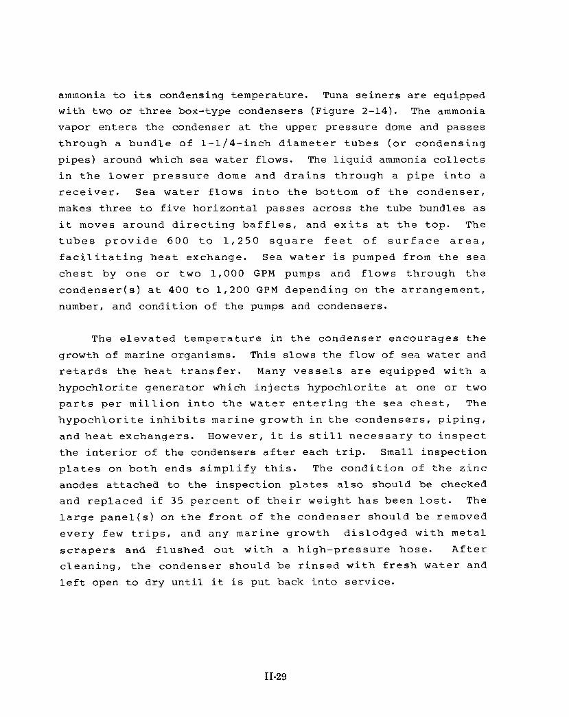
ammonia t o i t s condensing temperature. Tuna s e i n e r s a r e equipped with two o r t h r e e box-type condensers (Figure 2-14) . The ammonia
vapor e n t e r s the condenser a t t he upper pressure dome and passes
th rough a bund le of 1-1 /4- inch d i a m e t e r t u b e s ( o r condens ing
p ipes) around which sea water flows. The l i q u i d ammonia c o l l e c t s
i n t h e lower p r e s s u r e dome and d r a i n s th rough a p i p e i n t o a
r e c e i v e r . Sea w a t e r f l o w s i n t o t h e bot tom of t h e condense r ,
makes t h r e e t o f i v e hor izonta l passes across the tube b u n d l e s a s
it moves around d i r e c t i n g b a f f l e s , and e x i t s a t t h e t o p . The
t u b e s p r o v i d e 6 0 0 t o 1 , 2 5 0 s q u a r e f e e t o f s u r f a c e a r e a ,
f a c i l i t a t i n g h e a t exchange. Sea w a t e r i s pumped from t h e s e a
c h e s t by one o r two 1 ,000 GPM pumps and f l o w s th rough t h e
c o n d e n s e r ( s ) a t 400 t o 1 , 2 0 0 G P M depending on t h e a r r angemen t ,
number, and condi t ion of t h e pumps and condensers.
The e l e v a t e d t e m p e r a t u r e i n t h e condenser encourages t h e
growth of marine organisms. This slows t h e flow of sea water and
r e t a r d s t h e h e a t t r a n s f e r . Many v e s s e l s a r e equipped w i t h a
hypochlor i te genera tor w h i c h i n j e c t s hypochlor i te a t one o r two
p a r t s p e r m i l l i o n i n t o t h e w a t e r e n t e r i n g t h e s e a c h e s t , The
h y p o c h l o r i t e i n h i b i t s mar ine growth i n t h e condense r s , p i p i n g ,
and h e a t exchangers . However, it i s s t i l l n e c e s s a r y t o i n s p e c t
t h e i n t e r i o r of t h e condensers a f t e r each t r i p . Small i n spec t ion
p l a t e s on b o t h ends s i m p l i f y t h i s . The c o n d i t i o n of t h e z i n c
anodes a t tached t o t h e inspec t ion p l a t e s a l s o should be checked
and r e p l a c e d i f 35 p e r c e n t of t h e i r we igh t h a s been l o s t . The
l a r g e p a n e l ( s ) o n t h e f r o n t of t h e condenser shou ld be removed
e v e r y few t r i p s , and any mar ine growth d i s l o d g e d w i t h me ta l
s c r a p e r s and f l u s h e d o u t w i t h a h i g h - p r e s s u r e hose . A f t e r c l e a n i n g , t h e condenser should be r i n s e d w i t h f r e s h w a t e r and
l e f t open t o dry u n t i l it i s put back i n t o serv ice .

U!P!X? PR€SS'K DOME
6AFF'Eh (TYF?)
I t---------- -- --rr-- - I I I J'EWKN7ER I I I >SUlLE7
-
ll ITUBES
LOWER PP€PiUk?.E DOME
Figure 2-1 4. Box-Type Condenser
11-30

A condenser should ----- never s i t p a r t i a l l y f u l l of e i t h e r s a l t
w a t e r o r f r e s h w a t e r . I f t h e f l o w of s e a w a t e r i s s topped , t h e
c o n d e n s e r m u s t b e d r a i n e d , f l u s h e d w i t h f r e s h w a t e r , and
completely d r i ed t o prevent corrosion.
A p ressure equal iz ing l i n e r u n s from the upper pressure dome
of each condenser t o t h e r ece ive r t o prevent l i n e pressure bu i ld -
up i n t h e r e c e i v e r and a r e v e r s a l of ammonia f low.
The purge valve on t h e top of each condenser permi ts removal
of non-condensable gases ( p r i n c i p a l l y a i r ) from t h e system. The
presence of non-condensables inc reases t h e high-side pressure and
r e d u c e s t h e e f f i c i e n c y of t h e r e f r i g e r a t i o n sys tem. P r i o r t o
p u r g i n g , t h e s h u t - o f f v a l v e on t h e ammonia i n l e t l i n e t o t h e
condenser i s c l o s e d , a l t h o u g h t h e w a t e r f low i s m a i n t a i n e d and
the ammonia discharge l i n e remains open. When t h e condenser has
coo led , a hose w i t h one end i n a bucke t of w a t e r i s f i r m l y
at tached t o t h e purge valve, which i s opened s l i g h t l y , r e l eas ing
t h e non-condensables . Ammonia i n t h e bucke t i s d e t e c t e d by
c r a c k i n g o r snapping n o i s e s and a c h a r a c t e r i s t i c pungent odor .
A t t h e f i r s t s i g n of ammonia t h e purge v a l v e shou ld be c l o s e d .
I f t h e sys tem c o n t a i n s a l a r g e amount of a i r , i t may need t o b e
purged severa l t imes. Between each purging t h e condenser should
be operated long enough t o reach normal opera t ing temperature.
Idea l ly , before purging, t h e r e f r i g e r a t i o n system should be
s h u t down f o r two t o t h r e e days w i t h a l l t h e ammonia v a l v e s t o t h e condense r s open. T h i s a l l o w s t h e non-condensable g a s e s t o
accumulate i n t h e system's high point-- the top of t h e condensers.
Although t h e comple t e r e f r i g e r a t i o n sys tem can r a r e l y b e s h u t
o f f f o r so long, one condenser can be purged a t a t ime while t h e
r e s t of t he system i s working.
11-31

Rec e i ve r --
The r e c e i v e r ( F i g u r e 2 - 1 5 ) i s a h i g h - p r e s s u r e c y l i n d r i c a l
s t e e l ves se l t h a t has t h e capac i ty t o hold a l l t h e l i q u i d ammonia
i n t h e sys tem ( g e n e r a l l y abou t 2 , 0 0 0 pounds) . One o r two
r e c e i v e r s a r e i n s t a l l e d i n t h e p i p e a l l e y a l l o w i n g g r a v i t y t o
d r a i n t h e l i q u i d ammonia t o them from t h e condensers on the wet
deck. The s i g h t g l a s s f o r checking t h e amount of l i q u i d ammonia
i n t h e r e c e i v e r s i s secu red a t t h e t o p and bot tom w i t h s h u t - o f f
v a l v e s . These v a l v e s should b e opened o n l y when checking t h e
l i q u i d l e v e l t o r educe t h e r i s k of a dangerous ammonia l e a k i n case of s i g h t g l a s s breakage.
The i n l e t l i n e t o the rece iver i s separated from t h e o u t l e t
l i n e t o p r e v e n t d i r t and sed imen t s t i r r e d up by t h e incoming
l i q u i d from enter ing t h e o u t l e t . The o u t l e t pipe extends near t o
t h e tank bottom. S u f f i c i e n t l i q u i d ammonia should be kept i n t h e
r ece ive r t o cover the end of t he o u t l e t pipe. The shut-off valve
c l o s e s t t o t h e r e c e i v e r on t h e l i q u i d l i n e i s o f t e n c a l l e d t h e "k ing va lve ' ' s i n c e i t s c l o s u r e w i l l s t o p t h e f low of ammonia t o
t h e sys tem. I n t h e e v e n t of a major l e a k i n t h e sys t em, t h i s
valve m u s t be closed. Many s e i n e r s a l s o have an e l e c t r o n i c a l l y
o p e r a t e d k i n g v a l v e w i t h a c o n t r o l s w i t c h l o c a t e d o u t s i d e t h e
p i p e a l l e y . T h i s p e r m i t s t h e s h u t o f f of ammonia w i t h o u t
en ter ing t h e pipe a l l e y where dangerous l e v e l s of ammonia gas may
be present . The s t r a i n e r i n t h e l i q u i d l i n e t r a p s p a r t i c l e s t h a t
cou ld c l o g and damage t h e hand and a u t o m a t i c expans ion v a l v e s .
The s h u t - o f f v a l v e on t h e downstream s i d e of t h i s s t r a i n e r i s
o f t e n c a l l e d t h e ''queen valve. ' ' The o i l sump c o l l e c t s o i l t h a t
has been c a r r i e d p a s t t h e upstream o i l s epa ra to r s and t rap . This
oil shou ld be d r a i n e d r e g u l a r l y . P a r t i c u l a r c a r e should be
exercised during draining because of t he l a r g e amount of ammonia
i n t h e r e c e i v e r . Excess ive f o r c e should n o t be a p p l i e d t o t h e
11-32

//I 4
11-33

o i l d r a i n s h u t - o f f v a l v e because t h i s could b reak t h e v a l v e o f f t h e d r a i n p i p e . The d r a i n shou ld be p iped t o an open a r e a above
deck. I n s t a l l a t i o n of severa l shut-off valves and a separa te o i l
sump i n t h e d r a i n l i n e w i l l reduce t h e chance of an uncontrol led
r e l ease of ammonia.
P r e s s u r e Gaucres
I n a d d i t i o n t o t h e p r e s s u r e g a u g e s a t t h e i n l e t and
discharge of each compressor, p ressure gauges showing t h e suc t ion
p r e s s u r e i n t h e s u c t i o n man i fo ld f o r each compressor and t h e
high-side pressure i n t h e discharge header a r e mounted near t h e
c o n s o l e i n t h e eng ine c o n t r o l room. Of t en , gauges showing t h e
s u c t i o n p r e s s u r e i n each s u c t i o n h e a d e r a r e mounted n e a r t h e
doorway between the engine room and t h e pipe a l l e y .
There a r e two s c a l e s on each gauge face: one shows pressure
i n P S I G , and t h e o t h e r g i v e s t h e co r re spond ing e v a p o r a t i n g /
condensing t e m p e r a t u r e i n d e g r e e s F a r e n h e i t . Thus, gauges i n
s u c t i o n l i n e s can i n d i c a t e b o t h t h e s u c t i o n p r e s s u r e and t h e
corresponding ammonia evaporating temperature.
Temperature Sensors
O n some s e i n e r s t e m p e r a t u r e s e n s o r s a r e i n s t a l l e d i n t h e
i n l e t f o r t h e c i r c u l a t o r pump and a r e connected t o a temperature
i n d i c a t o r i n t h e eng ine c o n t r o l room. Th i s a l l o w s f o r remote
m o n i t o r i n g of t h e RSW o r b r i n e t e m p e r a t u r e . The l i f e of t h e s e
s e n s o r s i s u s u a l l y s h o r t and t h e y a r e r e p l a c e d o r augmented by
hanging o r f l o a t i n g thermometers i n t h e coaming ( t h e r a i sed curb
around t h e h a t c h open ing) . S i n c e t h e s e the rmomete r s a r e o f t e n
roughly t r e a t e d , t h e i r accuracy should be checked a t t h e s t a r t of
each t r i p . T h i s may be done by p l a c i n g t h e the rmomete r s i n i c e
11-34
w a t e r and n o t i n g the d i f f e r e n c e be tween the thermometer r e a d i n g
and 32OF. T h e ice w a t e r s h o u l d c o n t a i n e q u a l amounts o f ice and
w a t e r and be s t i r r e d r e g u l a r l y . T h e obse rved d i f f e r e n c e may be
w r i t t e n on the thermometer so s u b s e q u e n t t e m p e r a t u r e r e a d i n g s can
be c o r r e c t e d .
11-35

CHAPTER 111 OPERATION OF A REFRIGERATION SYSTEM
ROUTINE MAINTENANCE
The a b i l i t y of a r e f r i g e r a t i o n sys tem t o o p e r a t e a t peak
e f f i c i e n c y depends on c o n s c i e n t i o u s per formance o f r o u t i n e main tenance . Some of t h e main tenance r e g u l a r l y r e q u i r e d on
var ious components of t he r e f r i g e r a t i o n system has been described
i n Chapter 11. Much of t h i s main tenance can be per formed a f t e r
u n l o a d i n g t h e f i s h , when t h e r e i s l i t t l e d e m a n d f o r
r e f r i g e r a t i o n . T h i s m a i n t e n a n c e i n c l u d e s p u r g i n g non-
condensab le s from t h e condense r s : i n s p e c t i n g and c l e a n i n g t h e
condensers: removing o i l from t h e r ece ive r ( s ) , accumulators, o i l
t r a p s , and c o i l s : c leaning the s t r a i n e r s ; checking and replacing
t h e anodes ( " z i n c s " ) i n t h e condense r s , f i s h w e l l s , and t h e
c o m p r e s s o r ' s w a t e r c o o l i n g sys t em; and r e p l a c i n g l e a k i n g hand
expansion or shut-off valves . The compressors should be serv iced
according t o schedules provided i n t he manufacturer 's operat ing
i n s t r u c t i o n s . When maintenance i s performed, it should be noted
i n t h e e n g i n e room log . Comments should be i n c l u d e d i n t h e l o g
concerning t h e amounts of o i l , a i r , o r s c a l e removed, t h e weight
of anode remaining, and so fo r th .
A D J U S T I N G AMMONIA FLOW
The amount of l i q u i d ammonia passing through a bank of c o i l s
i s c o n t r o l l e d by t h e hand o r t h e a u t o m a t i c expans ion v a l v e s , o r
bo th . I d e a l l y , s u f f i c i e n t l i q u i d ammonia shou ld be f e d t o t h e
c o i l so t h e l a s t of t h e l i q u i d ammonia e v a p o r a t e s a t t h e c o i l ' s
e x i t from t h e wel l . Safe and e f f i c i e n t r e f r i g e r a t i o n i s produced
under t h e s e c o n d i t i o n s because t h e e n t i r e l e n g t h of t h e c o i l s
absorbs h e a t a t t h e maximum r a t e , t h e vapor leaving t h e c o i l has
111-1

minimum s u p e r h e a t , and l i q u i d ammonia w i l l n o t r e a c h t h e
compressors.
O n tuna se ine r s , a s p re sen t ly equipped, t he length of f r o s t
a l o n g t h e c o i l d i s c h a r g e l i n e i n t h e p i p e a l l e y i s t h e o n l y way
t o check t h e a d j u s t m e n t of t h e expans ion va lve . U s u a l l y , c h i e f
e n g i n e e r s t r y t o have t w o t o t h r e e f e e t of t h e d i s c h a r g e l i n e
c o v e r e d w i t h d r y f r o s t . The p r e s e n c e of f r o s t d o e s n o t
necessa r i ly i n d i c a t e l i q u i d ammonia i s present , s ince wet vapor
(vapor with suspended d rop le t s of l i q u i d ammonia) and cold vapor
cause f r o s t t o form. To be s u r e t h a t a c o i l h a s l i q u i d ammonia
t h r o u g h o u t , t h e expans ion v a l v e can be opened enough t o cause
l i q u i d ammonia t o c o l l e c t i n t h e a c c u m u l a t o r s , and t h e n t h e
expansion valve s e t t i n g can be reduced. However, t h i s increases
t h e r i s k t h a t l i q u i d ammonia w i l l r each t h e compresso r s and i s
the re fo re not recommended.
To prevent s t a rv ing t h e c o i l s of l i q u i d ammonia, t h e length
of f r o s t on t h e d i s c h a r g e may be i n c r e a s e d i n o r d e r t o l o w e r
e v a p o r a t o r t e m p e r a t u r e s (and s u c t i o n p r e s s u r e s ) . O n t h e o t h e r
hand, l i q u i d ammonia i n t h e suc t ion headers increases t h e load on
t h e sys tem w i t h o u t improving t h e speed a t which t h e f i s h a r e
c h i l l e d . Thus, t h e proper adjustment of expansion valves n e i t h e r
overfeeds nor underfeeds the c o i l s with l i q u i d ammonia. However,
because t h e r a t e of h e a t removal i s u s u a l l y l i m i t e d by t h e
a b i l i t y of t h e c o i l s t o a b s o r b h e a t r a t h e r t h a n by t h e c a p a c i t y
of t h e compressors t o r e f r i g e r a t e , engineers p r e f e r t o s l i g h t l y
overfeed t h e c o i l s than t o underfeed them.
Hand expansion valves have l a r g e c a p a c i t i e s and consequently a r e r a r e l y opened more t h a n one-ha l f t o one t u r n and a r e o f t e n
ad jus ted s l i g h t l y by gen t ly tapping t h e hand wheel with a hammer.
Automat ic expans ion v a l v e s have s m a l l e r c a p a c i t i e s and o f t e n
111-2

need severa l t u r n s t o produce t h e proper r e f r i g e r a n t flow. Even
when f u l l y open, some a u t o m a t i c s do n o t a l l o w f r o s t t o form on t h e d i s c h a r g e , i n d i c a t i n g t h e c o i l s r e q u i r e more ammonia. I n
t h i s c a s e t h e a u t o m a t i c should be r e p l a c e d w i t h one of l a r g e r
capaci ty . I f a replacement i s not ava i l ab le , t h e hand expansion
t o t h e same c o i l can be opened s l i g h t l y t o i n c r e a s e t h e ammonia
flow t o the wel l .
When a l a r g e number of we l l s a r e r e f r i g e r a t e d , i c e bui ldup
around t h e expansion valves and on t h e suc t ion headers is common,
however, t h i s i n h i b i t s t he a b i l i t y t o determine length of f r o s t
coming from one c o i l o r w e l l . A w e l l , t h a t h a s had i t s expans ion
v a l v e s opened s i g n i f i c a n t l y ( s u c h a s a f t e r b r i n i n g ) , can be
a t t a c h e d t o a s e p a r a t e s u c t i o n heade r . F r o s t f o r m a t i o n on t h i s
suc t ion header w i l l show c l e a r l y and enable t h e expansion valves
t o be c u t back before t h e system i s flooded.
SUCTION PRESSURE
Most ch ief engineers t r y t o maintain a suc t ion pressure of
a b o u t 1 5 P S I G i n b r i n e d o r d r i e d w e l l s . T h i s p r o d u c e s a
temperature of -l°F i n t he c o i l s and promotes rap id h e a t removal,
w i t h o u t exceeding t h e maximum compress ion r a t i o . I f s u c t i o n
pressures below 15 P S I G a r e used, t h e compression r a t i o should be
checked p e r i o d i c a l l y , because t h e maximum l i m i t s can be exceeded
w i t h o n l y a s l i g h t d e c r e a s e i n s u c t i o n p r e s s u r e o r i n c r e a s e i n discharge pressure.
Decreas ing t h e s u c t i o n p r e s s u r e d e c r e a s e s a c o m p r e s s o r ' s
r e f r i g e r a t i n g c a p a c i t y and i n c r e a s e s t h e power r e q u i r e d t o
produce one ton of r e f r i g e r a t i o n (Table 2 - 1 ) . Figure 3-1 shows
t h i s e f f e c t on t h e performance of a 6-cylinder compressor a t 185 P S I G condensing pressure. T h i s reduct ion i n compressor capac i ty
111-3

I I
Power Required
4 I
Refrigeration Capacity /
1
# #
- 3.0
-
- 2.5 h
c 0 i. \ e, z
- a v
c 0
-2.0 ; rc k a, 0 .d k - w a, c: IH 0
-1.5 2 E-
k al a
- a al k .d =I c7 a, e: k
0 a
- 1.0
- 0.5
0 _ I I I I I I I I I I I , L o 10 15 20 25 30 35 40 45 50 55 5
Suction Pressure (PSIG)
Figure 3-1 . Compressor Refrigeration Capacity and Power Required at Different Suction Pressures
111-4

i s n o t c r i t i c a l s i n c e t h e speed w i t h which a t u n a s e i n e r ' s
r e f r i g e r a t i o n sys tem can c h i l l and f r e e z e a w e l l of f i s h i s l i m i t e d by t h e c o i l s ' a b i l i t y t o a b s o r b and remove h e a t . Calcu la t ions based on t h e o r e t i c a l values and a c t u a l d a t a (Glassen
and C o t t r e l l , 1984) show t h a t t h e two 1 , 0 0 0 f o o t banks o f c o i l s
i n a f i s h w e l l a r e a b l e t o supp ly a t o t a l of be tween 1 5 t o 2 0
tons of r e f r i g e r a t i o n .
To achieve the maximum f reez ing r a t e w i t h t h i s evaporator-
l i m i t e d system, t h e suc t ion pressure should be held a s low a s t h e
compresso r s ' l i m i t s a l l o w . T h i s low p r e s s u r e m a i n t a i n s t h e
g r e a t e s t temperature d i f f e r e n c e between t h e c o i l s and t h e b r i n e
and f i s h , a l l o w i n g t h e c o i l s t o remove h e a t a s q u i c k l y a s
poss ib le . The r e f r i g e r a t i n g capac i ty of t h e c o i l s i n a wel l w i l l
va ry depending on t h e i r l e n g t h and t h e e f f i c i e n c y of ammonia
f low. P e r i o d i c c l e a n i n g of s t r a i n e r s and use of h i g h - s u c t i o n
p r e s s u r e t o remove o i l from t h e c o i l s e n s u r e s t h a t t h e c o i l s
o p e r a t e a t a maximum c a p a c i t y . B r i n e f l o w m u s t a l s o b e
maintained over t he c o i l s and f i s h f o r maximum h e a t removal.
When a heavy l o a d i s p u t on t h e r e f r i g e r a t i o n sys t em, t h e
s u c t i o n p r e s s u r e i n c r e a s e s i f t h e amount of ammonia p a s s i n g
through the system exceeds t h e compressor's capaci ty . Additional
compressors can be connected t o t h i s suc t ion l i n e t o maintain t h e
d e s i r e d p r e s s u r e . C o m p r e s s o r s f o r t h i s p u r p o s e c a n b e
d i s c o n n e c t e d from t h e "co ld" s u c t i o n l i n e f o r s e v e r a l h o u r s o r
even a day without a s i g n i f i c a n t temperature increase i n t h e cold
wel l s . As t h e temperature i n t h e w e l l s i s reduced, t h e expansion
v a l v e s m u s t be c u t back t o r educe t h e f low of ammonia and a v o i d
f 1 ooding t h e compressors.
S u c t i o n p r e s s u r e can be a d j u s t e d by v a r y i n g t h e number of
compresso r s ( a n d / o r compressor c y l i n d e r s under l o a d ) and t h e
111-5

expansion valve setting. However, the expansion valves should always be opened enough to form frost on the coil discharge-- otherwise a lower suction pressure will be achieved by starving the coils and reducing their effectiveness.
DISCHARGE PRESSURE
The discharge pressure should be kept as low as possible to reduce compressor wear, the introduction of oil into the refrigeration system (due to oil blown by the piston rings), the compression ratio (allowing a lower suction pressure to be used), the power required to run the compressor, and the power used per ton of refrigeration produced (Table 2-1). The effect of varying condensing pressure on the performance of a 6-cylinder compressor, operating with a 15.7 P S I G suction pressure, is shown in Figure 3-2. The high-side pressure may be limited by purging non-condensables from the system and cleaning the condenser. The discharge pressure can be reduced by increasing water flow through the condensers. This is done by turning on an extra pump--particularly if the pressure rises in response to a sudden increase in load. Worn impellers on the condenser water pumps can cause the discharge pressure to increase due to inadequate cooling of the discharge gas in the condenser. Superheating of the vapor in the suction lines raises the discharge pressure. Suction lines are often insulated when they have been installed through areas of high temperatures. Caution should be used when the hot gas return line is opened to remove liquid ammonia from an accumulator.
USE OF SUCTION HEADERS
The refrigeration system piping can be connected so that one suction header serves all the wells and compressors in a
111-6

60 - 2 . 0
h
c 0
E+ - \ cr z m
i;
v
+
.ti 4J rd k a, 0, .ti k w a E
-1.5 ; G 0 E?
k a, k
a a, k .ti =I F a, p:
k a, 3 0 a
-
I
-1.0 5
L O
h
c 0
fn 45 c 0 H v
h c, -ti u rd ch rd u
3 0
/I //
I /
/ /
/ /
/ /
/ /
I /
/ /I / Power Required
// Per Ton I /’
/ Refrigeration / Capacity
/ /
/
r
0 J I I I I I I I I I I I I I
1 0 0 1 2 0 1 4 0 1 6 0 1 8 0 2 0 0 Condensing Pressure (PSIG)
Figure 3-2. Compressor Ref rigeration Capacity and Power Required at Different Condensing Pressures
111-7
"connected1 ' sys t em, o r so t h a t d i f f e r e n t s u c t i o n h e a d e r s a r e a t t a c h e d t o v a r i o u s w e l l s and compressors i n a " s p l i t " sys tem.
I n t he l a t t e r case, one suc t ion header (hot l i n e ) i s at tached t o
w e l l s c o n t a i n i n g RSW or b r i n e and f i s h w i t h t e m p e r a t u r e s above
t h e f i n a l f rozen s torage temperature, and another suc t ion header
( c o l d l i n e ) i s connec ted t o b r i n e d o r d r i e d w e l l s h e l d a t t h e
s t o r a g e t e m p e r a t u r e . The number of compresso r s a t t a c h e d t o
e i t h e r l i n e i s a d j u s t e d d e p e n d i n g on t h e demand f o r
r e f r i g e r a t i o n .
Use of a s i n g l e suc t ion header e l imina te s valve handling and
also e l i m i n a t e s mistakes involved i n t h e mul t ip l e header s e t up.
However, i n t h e connected system, changing suc t ion pressure can
n e c e s s i t a t e readjustment of a l l t h e hand and automatic expansion
v a l v e s . With a s p l i t sys tem t h e s u c t i o n p r e s s u r e i n t h e c o l d
l i n e u s u a l l y does n o t v a r y and t h e r e f o r e hand o r a u t o m a t i c
expansion valve s e t t i n g s a r e adjusted only when a wel l i s f i r s t
a t tached t o t h a t header. The range of suc t ion pressure t h a t can
be used i n a connected system i s somewhat l i m i t e d s ince t h e c o i l
temperature i n w e l l s wi th f rozen f i s h m u s t be below t h e s to rage
temperature.
OPERATION D U R I N G F I S H HANDLING ~-
A l t h o u g h f i s h h a n d l i n g a n d t h e o p e r a t i o n o f t h e
r e f r i g e r a t i o n sys tem a r e t r e a t e d i n s e p a r a t e c h a p t e r s i n t h i s
manual, they a r e c lose ly interconnected. The remainder of t h i s
chapter b r i e f l y descr ibes adjustment of t h e r e f r i g e r a t i o n system
d u r i n g f i s h h a n d l i n g . Chapter IV i n c l u d e s a more d e t a i l e d
d e s c r i p t i o n of t h e b r i n e immersion method f o r p r e s e r v i n g f i s h ,
t h e opera t ion of t h e b r ine t r a n s f e r system, and t h e temperature
changes n o r m a l l y observed d u r i n g d i f f e r e n t s t a g e s of f i s h hand1 ing .
111-8

The g o a l behind t h e s u g g e s t i o n s g i v e n i n t h e f o l l o w i n g
s e c t i o n s i s t o m a i n t a i n f i s h q u a l i t y . Although e v e r y c h i e f
e n g i n e e r wants t o do t h i s , c o n d i t i o n s encoun te red d u r i n g a
f i s h i n g t r i p can r e q u i r e t h a t t h e b e s t a v a i l a b l e o p t i o n s ( n o t
necessa r i ly t h e p re fe r r ed ones) be used t o handle t h e f i s h . When
d e c i d i n g how t o cope w i t h a g i v e n s i t u a t i o n it shou ld be no ted
t h a t t h e q u a l i t y of f i s h i s b e s t preserved by (1) minimizing t h e
t i m e h e l d i n RSW o r b r i n e , ( 2 ) l i m i t i n g t h e amount s t o r e d i n a
w e l l (no t overpacking), ( 3 ) f reez ing a s r ap id ly and a s soon a f t e r
c a t c h i n g a s p o s s i b l e , and (4 ) s t o r i n g a t t h e l o w e s t and most
s t ab1 e temperature poss ib le .
Ch i l l i ng Sea Water - and Brine
When beginning t o c h i l l sea water and b r i n e , r e l a t i v e l y high
(40-60 P S I G ) s u c t i o n p r e s s u r e s shou ld b e used. T h i s h e l p s t o
remove o i l from t h e c o i l s because t h e warm w a t e r t e m p e r a t u r e
r educes t h e o i l ' s v i s c o s i t y and t h e h i g h s u c t i o n p r e s s u r e
increases t h e flow r a t e of t he ammonia. Higher suc t ion pressure
pu t s added s t r a i n on t h e e l e c t r i c motors and V-belts d r iv ing t h e
compressors and on the c o i l s and suc t ion headers. Consequently,
t hese components m u s t be i n good condi t ion i f such high suc t ion
pressures a r e used.
With s u c t i o n p r e s s u r e s above 40 PSIG, f r o s t w i l l n o t form
r e a d i l y on t h e c o i l discharge, even when it conta ins some l i q u i d
ammonia. I n t h i s c a s e , t o d e t e r m i n e when l i q u i d ammonia i s
r e a c h i n g t h e end of a c o i l , t h e c h i e f e n g i n e e r m u s t compare t h e
t e m p e r a t u r e a t t h e c o i l i n l e t and d i s c h a r g e by touch ing each
l o c a t i o n . When t h e t e m p e r a t u r e i s t h e same and t h e c o i l
d i s c h a r g e does n o t r e a d i l y warm up when touched , t h e c o i l h a s l i q u i d ammonia throughout. The bottom h a l f of t h e c o i l should be
f e l t for b e s t r e s u l t s . The p o s i t i o n of l i q u i d ammonia along t h e
suc t ion l i n e may be found by manually checking t h e temperature.
111-9

A s t h e t e m p e r a t u r e of t h e s e a w a t e r f a l l s , t h e hand
expansion valves m u s t be c u t back t o prevent flooding t h e system.
The sys tem f l o o d s r e l a t i v e l y q u i c k l y , n e c e s s i t a t i n g c o n s t a n t
a t t e n t i o n t o r e f r i g e r a t i o n sys tem a d j u s t m e n t . T h e r e f o r e , t h i s
p rocedure should be u s e d o n l y when i n t e r r u p t i o n s a r e u n l i k e l y .
When t h e water temperature comes wi th in 15OF of t h e evaporating
temperature, t h e suc t ion pressure should be lowered about 5 PSIG
by i n c r e a s i n g t h e number of compressor c y l i n d e r s under l o a d
and/or c los ing the hand expansion valve a l i t t l e more.
When s e a w a t e r r e a c h e s 2g°F, h a l f a d e g r e e a b o v e i t s
f r e e z i n g p o i n t , t h e B P R can be employed t o h o l d t h e t e m p e r a t u r e cons tan t , prevent ing i c e from forming on t h e c o i l s . Ice a c t s a s
i n s u l a t i o n and i n t e r f e r e s with hea t removal. The BPR i s normally
s e t a t abou t 3 7 P S I G . A t 3 7 P S I G , l i q u i d ammonia b o i l s a t 23OF; however, i c e does not normally form a t t h i s s e t t i n g because the
p r e s s u r e i n t h e c o i l s i s u s u a l l y above 3 7 PSIG--the B P R gauge
measures the suc t ion pressure a f t e r t he pressure drop along t h e
c o i l s .
Some chief engineers p r e f e r t o a l t e r n a t e l y form i c e and then
shut o f f t h e r e f r i g e r a t i o n and allow it t o melt . This procedure
can c a u s e problems i f t h e i c e does n o t m e l t c o m p l e t e l y d u r i n g
l o a d i n g and packing . The f i s h c a p a c i t y of t h e w e l l and t h e
a b i l i t y of t h e r e f r i g e r a t i o n system t o c h i l l t h e f i s h i s l i m i t e d
by t h e r ema in ing i c e . O n t h e o t h e r hand, i c e r e p r e s e n t s s t o r e d
r e f r i g e r a t i o n t h a t a s s i s t s t h e sys tem t o remove h e a t from t h e
f i s h d u r i n g i n i t i a l c h i l l i n g . However, i t i s d i f f i c u l t t o
e s t i m a t e t h e amount of i c e needed f o r t h i s purpose . S i n c e overest imat ion r e s u l t s i n t h e problems previously descr ibed, t h e
amount of i c e should be l imi t ed .
111-10

Chi l l i ng t h e F ish
T h e hand expansion valves serving t h e w e l l ( s ) t o which f i s h
w i l l be added shou ld be opened and t h e B P R d i s c o n n e c t e d j u s t
p r i o r t o b r a i l i n g t h e f i s h on board. During b r a i l i n g and
c h i l l i n g , t h e amount of f r o s t on t h e s u c t i o n l i n e s shou ld b e
checked r egu la r ly t o a d j u s t t h e hand expansion valves and cont ro l
t h e flow t o prevent e i t h e r flooding t h e compressors w i t h l i q u i d
ammonia o r s t a r v i n g t h e c o i l s . A s t h e t e m p e r a t u r e i n t h e w e l l
d r o p s , l e s s h e a t i s absorbed by t h e c o i l s , b o i l i n g o f f l e s s
l i q u i d ammonia, leaving more i n t he c o i l , and requi r ing t h e hand
expansion valve t o be c u t back pe r iod ica l ly . Following b r a i l i n g ,
t h e suc t ion pressure should be held as low a s poss ib l e u n t i l the
temperature i s w i t h i n 1°F of R S W ' s f reez ing po in t or 10°F of t h e
f r e e z i n g p o i n t of b r i n e . The l a r g e r d i f f e r e n c e i s r e q u i r e d f o r
b r i n e because of t h e i n a c c u r a c i e s i n f r e e z i n g p o i n t s measured
w i t h a hydrometer ( s e e Chapter I V ) . The hand expans ion v a l v e s
shou ld t h e n be a d j u s t e d and t h e B P R employed t o m a i n t a i n a
constant temperature i n t he wel l .
Freezina the F i s h
The a d j u s t m e n t of t h e r e f r i g e r a t i o n sys tem when f r e e z i n g
f i s h i s t h e same a s t h a t d e s c r i b e d above f o r c h i l l i n g f i s h i n b r i n e . I t i s p r e f e r a b l e t o f r e e z e o n l y one w e l l of f i s h a t a
t i m e , t h u s a l l o w i n g t h e maximum amount of r e f r i g e r a t i o n t o b e
a p p l i e d . Maximum r e f r i g e r a t i o n should be a p p l i e d u n t i l t h e
t e m p e r a t u r e i n t h e w e l l i s a s low a s t h e f r e e z i n g p o i n t of t h e
b r i n e o r t he operat ing l i m i t s of t h e compressors allow. A t t h i s
po in t t h e wel l should be connected t o t h e cold suc t ion l i n e ( i f a
s p l i t system i s u s e d ) and the automatic expansion valves should
be a p p l i e d . I f an a u t o m a t i c was n o t u s e d o n t h e p r e v i o u s t r i p ,
t h e i n l e t s t r a i n e r should be cleaned i n so lvent and t h e ad jus t ing
111-11

s p r i n g s h o u l d be s e t i n t h e m i d d l e o f i t s r a n g e t o p r e v e n t l i q u i d
ammonia from f l o o d i n g t h r o u g h when the v a l v e i s opened.
Drvina the W e l l s
Once t h e d e s i r e d s t o r a g e t e m p e r a t u r e i s r e a c h e d , b r i n e
s h o u l d be removed ( u n l e s s the w e l l w i l l be unloaded w i t h i n s e v e n
d a y s ) . T h e a u t o m a t i c s s h o u l d be a d j u s t e d f o r one t o f o u r f e e t of
f r o s t o n t h e c o i l d i s c h a r g e l i n e . F r e q u e n t o b s e r v a t i o n of t h e
p o s i t i o n of the f r o s t l i n e and r e a d j u s t m e n t o f the a u t o m a t i c s i s
r e q u i r e d d u r i n g t he f i r s t 24 h o u r s o f o p e r a t i o n . Hand e x p a n s i o n
v a l v e s c a n be u s e d t o c o n t r o l t h e r e f r i g e r a t i o n t o a d r i e d w e l l
i n the a b s e n c e of f u n c t i o n a l a u t o m a t i c s . However, hand e x p a n s i o n
v a l v e s must be r e a d j u s t e d m o r e f r e q u e n t l y .
P reDar ina t o Unload
A f t e r a w e l l i s r e b r i n e d ( s e e Chapter I V , U n l o a d i n g t h e
F i s h ) , t h e e x p a n s i o n v a l v e s a r e s h u t o f f a n d t h e y r e m a i n o f f
u n t i l t h e b r i n e t e m p e r a t u r e i n c r e a s e s o n e o r t w o d e g r e e s ,
a l l o w i n g i c e t o m e l t . Then the hand e x p a n s i o n v a l v e s are used t o
m a i n t a i n t h e d e s i r e d t e m p e r a t u r e , u s u a l l y 1 2 t o 130F. J u s t pr ior t o the s t a r t o f u n l o a d i n g , t he b r i n e i s pumped o f f . N e a r l y
a l l o f t h e ammonia i n t h e c o i l s i s removed b y s h u t t i n g o f f t h e
e x p a n s i o n v a l v e s and c o n n e c t i n g the s u c t i o n l i n e s f r o m t he w e l l s
t o be u n l o a d e d t o a c o m p r e s s o r ( s ) , a n d r u n n i n g t h e compressor
u n t i l t h e s u c t i o n p r e s s u r e i s b e l o w 5 P S I G . T h i s r e d u c e s t h e
a m o u n t of ammonia r e l e a s e d i n t o a w e l l i f a c o i l i s b r o k e n . T h i s
p r o c e d u r e i s r e p e a t e d w h e n e v e r t h e s u c t i o n p r e s s u r e i n t hose
co i l s i n c r e a s e s t o 10 PSIG due t o warming of the coils.
111-12

CHAPTER IV TUNA-HANDLING PROCEDURES
PREPARATION FOR STORAGE
Cleanina t h e Wells
A w e l l shou ld be c l eaned t h o r o u g h l y i n p r e p a r a t i o n f o r
r e c e i v i n g f i s h . C lean ing i n v o l v e s removing f i s h f l e s h , s k i n ,
and bone from t h e w e l l , and washing t h e w e l l s u r f a c e s w i t h a
h i g h - p r e s s u r e s e a w a t e r hose. P a r t i c u l a r a t t e n t i o n shou ld be
paid t o cleaning t h e screen covering t h e c i r c u l a t o r pump in t ake
and t h e w e l l s ' d r a i n s . Thorough c l e a n i n g h e l p s t o e n s u r e
adequa te c i r c u l a t i o n and p r e v e n t s t h e b u i l d u p o f s p o i l a g e
b a c t e r i a p r i o r t o t h e add i t ion of f i s h .
The w e l l s shou ld be c l e a n e d a f t e r t h e y a r e unloaded a t t h e
conclusion of each t r i p . Decomposition of organic ma te r i a l such
a s f i s h f l e s h may produce a poisonous gas--which can be f a t a l i n
an e n c l o s e d a r e a l i k e a f i s h w e l l . I f t h e r e i s a d e l a y b e f o r e a
w e l l can be c l e a n e d , t h e h a t c h should be removed and a f a n used
t o a e r a t e t h e w e l l u n t i l work b e g i n s . I f a p e r s o n c o l l a p s e s
w h i l e working i n a w e l l , t h e r e s c u e r should use a l i f e l i n e and a
self-contained brea th ing apparatus so t h a t t h e rescuer w i l l no t
become another vict im.
Wells used t o s t o r e fue l should be cleaned thoroughly before
f i s h a r e s towed. A s m a l l amount of f u e l i s s u f f i c i e n t t o
contaminate the tuna and cause r e j e c t i o n by t h e cannery. A s much
f u e l a s p o s s i b l e shou ld be pumped from t h e w e l l , t h e d r a i n s
opened, a l l s u r f a c e s washed w i t h t h e h i g h - p r e s s u r e s e a w a t e r
hose , and t h e s e a w a t e r removed. Next, a d e t e r g e n t s o l u t i o n
shou ld be sprayed o n a l l s u r f a c e s w i t h a h i g h - p r e s s u r e "choo-
choo'' g u n . T h e d e t e r g e n t shou ld b e a non-flammable, non- tox ic
IV-1

w a t e r s o l u b l e d e g r e a s e r approved by t h e F D A f o r u se on food
processing equipment. P a r t i c u l a r a t t e n t i o n should be paid t o t h e
s p a c e s between t h e ammonia c o i l s and t h e w e l l s u r f a c e s and t h e
in s ide of t h e c i r c u l a t o r discharge pipe. The de tergent should be
washed o f f w i t h t h e h i g h - p r e s s u r e s e a w a t e r h o s e , and t h e s e a
water and de te rgen t removed. The d r a i n s should be closed and sea
water pumped i n t o t h e wel l and the wel l allowed t o overflow over
t h e coaming. Af te r a few minutes, t h e overflowing i s stopped and
t h e c i r c u l a t o r pump turned on. After an hour o r so, t he water i s
checked f o r t h e p r e s e n c e of any f u e l s l i c k . I f any f u e l i s found, t h e de t e rgen t wash should be repeated: t h e wel l should be
rechecked and t h e p r o c e s s r e p e a t e d u n t i l no ev idence of f u e l i s
observed.
I f t h e wa l l s of a w e l l a r e cracked, fue l w i l l seep i n t o the
surrounding in su la t ion . T h i s f ue l cannot be removed completely
by washing and it can l e a k b a c k i n t o t h e well and c o n t a m i n a t e t h e
f i s h . T h u s , f u e l shou ld neve r be s t o r e d i n c r acked w e l l s . RSW o r b r i n e s t o r e d i n a c r acked w e l l w i l l be absorbed by t h e
i n s u l a t i o n , reducing i n s u l a t i n g a b i l i t y and producing hot spo t s
i n t he wel l . For these reasons, cracked we l l s should be repa i red
a s soon a s poss ib le .
Preparing t h e Brine
Br ine i s p repa red a t t h e beg inn ing of a f i s h i n g t r i p by
adding a d e s i r e d amount of s a l t (sodium c h l o r i d e ) t o an empty
p a i r o f w e l l s , f i l l i n g t h o s e w e l l s w i t h c l e a n s e a w a t e r , c i r c u l a t i n g t h e sea water u n t i l t h e s a l t has d isso lved , applying
r e f r i g e r a t i o n t o t he b r i n e , and s t o r i n g it a t 0 t o 10°F. The
s a l t used f o r making b r i n e i s #1 g r a d e s e a s a l t , w i t h a g r a i n
s i z e e q u i v a l e n t t o a r i c e k e r n e l and c o n t a i n i n g l e s s t h a n one- h a l f p e r c e n t o r g a n i c and i n o r g a n i c i m p u r i t i e s . S a l t i s e i t h e r
IV-2

provided i n bulk o r i n sacks of var ious s i zes . S a l t from sources
o t h e r t h a n s e a w a t e r m u s t be ana lyzed t o e n s u r e no copper i s p r e s e n t . Copper r e a d i l y combines w i t h p r o t e i n i n t h e t u n a
caus ing a d i s c o l o r a t i o n ( m e t a l s t a i n ) when t h e canned f i s h i s
r e t o r t e d .
To c a l c u l a t e t h e amount of s a l t t o add t o a b r i n e s t o r a g e
w e l l , t h e volume of t h e wel l and t h e des i red b r i n e s a l i n i t y m u s t
be known. The s a l i n i t y d e s i r e d depends upon whether t h e b r i n e
w i l l be i n t e n t i o n a l l y d i l u t e d by l e a v i n g some RSW i n a w e l l
d u r i n g b r i n i n g , o r whether a l l t h e RSW w i l l be removed and
the re fo re d i l u t i o n w i l l be minimal.
Multiplying t h e volume of t h e wel l i n cubic f e e t t imes 7.48
( t h e number of ga l lons he ld i n one cubic foo t ) g ives t h e capac i ty
of t h e w e l l i n g a l l o n s . The amount o f s a l t t h a t m u s t be
c o n t a i n e d i n each g a l l o n o f b r i n e of a g i v e n c o n c e n t r a t i o n i s shown i n Tab le 4-1 , under "Pounds of S a l t p e r Ga l lon of Brine."
For example, a g a l l o n of e u t e c t i c b r i n e , s a l i n i t y = 23.3 percent ,
c o n t a i n s 2 . 2 8 7 pounds of sodium c h l o r i d e . S i n c e s e a w a t e r (3 .5
p e r c e n t s a l t ) a l r e a d y c o n t a i n s 0.299 pounds of s a l t p e r g a l l o n ,
an a d d i t i o n a l 1.988 pounds of s a l t m u s t be added t o each g a l l o n
of s e a w a t e r . M u l t i p l y i n g 1.988 t i m e s t h e w e l l c a p a c i t y i n
ga l lons g ives t h e weight of s a l t required.
To ensure t h a t a l l t h e s a l t added t o a b r i n e wel l d i s s o l v e s ,
t h e s o l u t i o n m u s t be a g i t a t e d . A s e c t i o n of hose 1 5 t o 2 0 f e e t
l ong , a t t a c h e d t o t h e c i r c u l a t o r d i s c h a r g e p i p e and hung t o t h e bottom of t h e b r i n e we l l , w i l l h e lp t o s t i r t h e s a l t a s t h e hose
moves back and f o r t h under t h e p r e s s u r e of t h e c i r c u l a t o r
discharge.
A s t h e c o n c e n t r a t i o n o f b r i n e i n c r e a s e s a n d / o r t h e
t e m p e r a t u r e d e c r e a s e s , s a l t d i s s o l v e s more s l o w l y . When
p r e p a r i n g b r i n e w i t h a s a l i n i t y above 2 4 p e r c e n t , t h e b r i n e
IV-3

Table 4-1 . Sodium Chloride Brine Characteristics
Salinity % NaCl
by Weight
0.0 1.0 2.0 3.0
4.0 5.0 6.0 7.0 8.0 9.0 10.0 11.0 12.0 13.0 14.0 15.0 16.0 17.0 18.0 19.0 20.0 21.0 22.0 23.0 23.3 24.0 25.0 26.0 26.4f
3.5"
Freezing Pointb
OF
+32 +31 +30 +29 +28.4 +2 8 +27 +25 +24 +23 +22 +20 +19 +17 +16 +14 +12 +11 + 9 + 7 + 5 + 2 0
- 3 - I Zd + 2e +13e +28e +60e
Pounds of Salt Per
Gallon Brine
0.000 0.084 0.169 0.255 0.299 0.342 0.432 0.522 0.613 0.705 0.800 0.894 0.990 1.088 1.187 1.257 1.388 1.491 1.596 1.701 1.805 1.917 2.027 2.139 2.252 2.287 2.366 2.482 2.599 2.647
Specific Gravity
1.000 1.008 1.014 1.022 1.026 1.029 1.036 1.044 1.051 1.059 1.066 1.074 1.081 1.089 1.097 1.104 1.112 1.119 1.127 1.135 1.143 1.151 1.159 1.168 1.175 1.178
1.192 1.201 1.204
1.184
Freezing Salometer Pointb Degrees OC
0 0.0 3.8 - 0.5 7.6 - 1.1 11.4 - 1.7 13.3 - 2.0 15.2 - 2.3 18.9 - 2.9 22.7 - 3.6 26.5 - 4.3 30.3 - 5.1 34.1 - 5.8 37.9 - 6.6 41.7 - 7.3 45.5 - 8.2 49.3 - 9.1 53.0 - 9.9 56.8 -10.9 60.6 -11.9 64.4 -12.9 68.2 -14.1 72.0 -15.2 75.8 -16.4 79.6 -17.8 83.3 -19.1
d 87.1 -20.7 88.3 -21.1 90.9 -16. ge 94.7 -10. 3e 98.5 - 2.4e 100.0 +15. 6e
aThis table applies only to brine at 60°F. For brine measure- ments taken at other temperatures, add 0.25 to the measured salinity for every 10 degrees the brine temperature is above 60°F, and deduct 0.25 for every 10 degrees below 60°F, before consulting the table.
increases. With continued cooling, the freezing point is lowered to the eutectic point (the lowest freezing point).
bTemperatures at which freezing begins. As ice forms, salinity
CApproximate salinity of sea water. dEutectic point (the lowest temperature at which a sodium chloride solution will remain a liquid).
e Saturation temperature. Reducing the temperature further results in formation of crystals of sodium chloride dihydrate (NaC1.2H20) until the eutectic point is reached. fSaturated brine at 60°F.
IV-4

should c i r c u l a t e u n t i l t he s a l i n i t y s t a b i l i z e s before c h i l l i n g .
F resh b r i n e shou ld b e s t o r e d a t a t e m p e r a t u r e 5OF above i t s f r e e z i n g p o i n t ( f p ) . T h i s s a f e t y margin shou ld be i n c r e a s e d t o
8O t o 10°F when s t o r i n g used b r i n e t h a t h a s p i cked up b l o o d ,
s l i m e , s o l u b l e p r o t e i n , and o t h e r " f o r e i g n " m a t e r i a l from f i s h .
The p r e s e n c e of t h e s e s u b s t a n c e s i n c r e a s e s t h e d e n s i t y of t h e
b r i n e , caus ing t h e s a l i n o m e t e r t o f l o a t h i g h e r i n t h e b r i n e ,
i nd ica t ing a g r e a t e r s a l i n i t y than i s a c t u a l l y present .
When s a l t i s s c a r c e a n d / o r e x p e n s i v e , b r i n e i s o f t e n
r e t a i n e d and used f o r s e v e r a l t r i p s . The f l u i d s and p r o t e i n
p i cked up by b r i n e d u r i n g ex tended use cause t h e measured
s a l i n i t y t o b e o v e r e s t i m a t e d by an a v e r a g e of 2 p e r c e n t a g e
p o i n t s . T h i s d i s c r e p a n c y m u s t be remembered when checking t h e
c o n c e n t r a t i o n o f b r i n e t o be used on a n o t h e r t r i p . Commonly,
s u f f i c i e n t s a l t t o increase t h e s a l i n i t y by 2 percent (about 0.2
of a pound per g a l l o n of b r i n e ) i s added t o previously used b r i n e
a t t h e beg inn ing of a t r i p . S i n c e t h i s b r i n e m u s t be k e p t c o l d
o r t h e o r g a n i c m a t e r i a l it c o n t a i n s w i l l s p o i l , e x t r a t i m e i s
needed t o completely d i s so lve added s a l t .
C h a r a c t e r i s t i c s of Brine -
S a l t l o w e r s t h e f r e e z i n g p o i n t of w a t e r by a p r e d i c t a b l e
amount ( F i g u r e 4-1 and Tab le 4 - 1 ) . T o f r e e z e t h e f i s h , t h e RSW (3.5 p e r c e n t sodium c h l o r i d e by w e i g h t ) w i t h an f p o f a b o u t
28.4OFr m u s t be r e p l a c e d w i t h b r i n e of g r e a t e r s a l i n i t y and a
lower fp . B r i n e s a r e o f t e n i d e n t i f i e d by t h e i r f reez j -ng p o i n t s
r a t h e r than t h e i r s a l t concentrat ion. For example, b r i n e wi th a
s a l i n i t y of 19 percent and a 50F f p may be c a l l e d a 5O br ine .
The l o w e s t f r e e z i n g p o i n t , c a l l e d t h e e u t e c t i c p o i n t , t h a t can be ach ieved i n a sodium c h l o r i d e b r i n e i s - 6 0 ~ a t 2 3 . 3
percent s a l i n i t y . Brine wi th a concentrat ion l e s s than e u t e c t i c
IV-5

70
60
50
40
3 0
2 0
10
0
Saturation Temperatures
I I I I I I I I I I I I
Y 1 I
4 Freezing Points
-10
- 2 0
16 2 0 24 28 3 2 0 4 8 12
Salinity (Percent Sodium Chloride by Weight)
Figure 4-1. Relationship of Freezing Point to Salinity of Brine
IV-6

br ine w i l l f reeze a t a higher temperature. When t h e temperature
of b r i n e i s reduced t o i t s f r e e z i n g p o i n t , p u r e i c e c r y s t a l s
form. The s a l t t h a t was d i s s o l v e d i n t h e now f r o z e n w a t e r
d i s s o l v e s i n t h e r ema in ing b r i n e , i n c r e a s i n g t h e s a l i n i t y . I f
h e a t c o n t i n u e s t o be removed, t h e p r o c e s s of pu re i c e c r y s t a l
f o r m a t i o n and s a l i n i t y i n c r e a s e c o n t i n u e s u n t i l t h e s o l u t i o n
r e a c h e s t h e e u t e c t i c p o i n t . When e u t e c t i c b r i n e f r e e z e s , a
mixture of pure i c e c r y s t a l s and s a l t c r y s t a l s (sodium ch lo r ide
d ihydra te ) forms.
When b r i n e s w i t h c o n c e n t r a t i o n s g r e a t e r t h a n e u t e c t i c a r e
cooled below t h e s a t u r a t i o n t e m p e r a t u r e s ( T a b l e 4 -1 and F i g u r e
4 - l ) , a p r e c i p i t a t e of s a l t forms. With add i t iona l cooling, s a l t
c o n t i n u e s t o p r e c i p i t a t e u n t i l t h e e u t e c t i c c o n c e n t r a t i o n i s
reached and then the b r i n e f reezes . Thus, t h e use of b r i n e wi th
a c o n c e n t r a t i o n g r e a t e r t h a n t h e e u t e c t i c p o i n t i n a w e l l w i t h
f i s h i s a w a s t e o f s a l t b e c a u s e i n c r e a s e d f r e e z i n g p o i n t
depression does not occur.
Measuring Brine S a l i n i t y --
T h e s a l i n i t y of b r ine i s usua l ly measured w i t h a hydrometer,
c a l l e d a sa l inometer , equipped wi th a small thermometer and two
s c a l e s , one ind ica t ing the percent sodium ch lo r ide by weight, t h e
o the r g iv ing the f reez ing po in t of t h e br ine . The sa l inometer i s c a l i b r a t e d f o r use i n so lu t ions a t 60OF. The small thermometer
i s des igned t o measure t h e t e m p e r a t u r e of t h e s o l u t i o n . I t s
t e m p e r a t u r e s c a l e a l s o shows t h e p e r c e n t s a l t by which t h e
s a l i n i t y reading m u s t be cor rec ted . I n genera l , 0.25 percent i s
added t o t h e s a l i n i t y of t h e s o l u t i o n f o r e v e r y l O 0 F t h e
s o l u t i o n ' s t e m p e r a t u r e i s above 60°F, and c o n v e r s e l y , t h e same amount i s s u b t r a c t e d f o r e v e r y 10°F t h e t e m p e r a t u r e i s below
60°F. For example, a s a l i n i t y r e a d i n g of 20.0 p e r c e n t i n b r i n e
IV-7

w i t h a t e m p e r a t u r e of 30°F i s c o r r e c t e d by s u b t r a c t i n g 0 .75
p e r c e n t ( 3 x . 2 5 p e r c e n t ) from t h e s a l i n i t y , r e s u l t i n g i n a v a l u e
of 1 9 . 2 5 p e r c e n t , w h i c h i s t h e n used t o d e t e r m i n e t h e f r e e z i n g
p o i n t .
To use t h e s a l i n o m e t e r , it should be p l a c e d i n a c o n t a i n e r
f i l l e d wi th t h e b r i n e sample and allowed t o f l o a t ; s a l i n i t y i s
read by noting t h e value where the top of t h e sal inometer emerges
from t h e b r i n e . The t e m p e r a t u r e of t h e b r i n e i s noted and t h e
c o r r e c t i o n f a c t o r a p p l i e d t o t h e o b s e r v e d s a l i n i t y . The
p l a s t i c c a r r y i n g c a s e o f t h e s a l i n o m e t e r c a n b e used a s t h e b r i n e
conta iner .
O c c a s i o n a l l y , hydromete r s marked w i t h s a l o m e t e r d e g r e e s
(OSAL) a r e used. These hydrometers, c a l l e d sal-ometers, i n d i c a t e
t h e p e r c e n t s a t u r a t i o n of t h e s o l u t i o n . The s c a l e i s from 0 t o
100 OSAL. Since a s a tu ra t ed so lu t ion (100 OSAL) a t 60°F conta ins
26.4 p e r c e n t s a l t , each OSAL r e p r e s e n t s abou t 0.26 p e r c e n t s a l t by weight. The procedure f o r u s i n g t he salometer i s t h e same a s descr ibed f a r t he sal inometer above, except t h e co r rec t ion f a c t o r
f o r t h e salometer i s one OSAL f o r every 10°F above o r below 60°F. A t a b l e such a s Table 4-1 m u s t be c o n s u l t e d t o d e t e r m i n e t h e
f reez ing po in t and s a l i n i t y a f t e r t h e OSAL measurement i s known.
Sequence of Well-Loading
The order i n which w e l l s a r e f i l l e d with f i s h i s determined
by t h e t r i m c h a r a c t e r i s t i c s of t h e s e i n e r and t h e c o n t e n t s ( s e a
w a t e r , b r i n e , f r e s h w a t e r , o r f u e l ) of t h e w e l l s . S i n c e t h e s e
f a c t o r s vary depending on t h e vesse l and expected t r i p length , no
s t a n d a r d r u l e s e x i s t r e g a r d i n g l o a d i n g s e q u e n c e . F o r a
p a r t i c u l a r b o a t , a l o a d i n g sequence p l a n should be deve loped a t
t h e beg inn ing of a t r i p and mod i f i ed i n r e s p o n s e t o f i s h i n g
IV-8
condi t ions. I n formulating t h i s plan, t he ch ief engineer should t r y t o (1) maximize t h e number of we l l s f i l l e d w i t h RSW o r b r i n e
and the re fo re a v a i l a b l e f o r f i s h s torage , ( 2 ) avoid drying w e l l s
(discussed below) ad jacent t o we l l s containing "warm" f u e l , sea
w a t e r , o r f r e s h w a t e r , ( 3 ) l i m i t t h e t i m e w e l l s of f u e l a r e
ad jacent t o w e l l s with f i s h , and (4 ) avoid s t o r i n g f i s h i n a w e l l t h a t i s between two w e l l s of f u e l .
When comple t e r e c o r d s abou t t h e c o n t e n t s and h a n d l i n g of
e a c h w e l l a r e m a i n t a i n e d , t h e p l a n n i n g and e x e c u t i n g o f
preserva t ion of tuna i s e a s i e r , and t h e handling techniques t h a t
work bes t can be i d e n t i f i e d . A sample form f o r r e c o r d i n g
important well-handling information i s provided i n Appendix C.
CATCHING THE F I S H
The q u a l i t y of t una f l e s h d e t e r i o r a t e s d u r i n g h a n d l i n g ,
f r e e z i n g , and s t o r a g e a s a r e s u l t of a combina t ion of complex
changes i n t h e f i s h t i s s u e caused by i t s own enzymes, b a c t e r i a ,
and c h e m i c a l r e a c t i o n s . The r a t e o f d e g r a d a t i o n d e p e n d s
p r i m a r i l y upon t h e temperature of the f ish--higher temperatures
cause more r a p i d loss of q u a l i t y . Rate of s p o i l a g e i s a l s o
a f f ec t ed by the length of exposure t o e levated temperatures , t h e
b i o c h e m i c a l c o n d i t i o n of t h e f i s h , and t h e t y p e and amount of
b a c t e r i a i n and on the f i s h . Chapter V provides a more d e t a i l e d
d iscuss ion of tuna spoi lage.
Sea w a t e r t e m p e r a t u r e s encoun te red by tuna s e i n e r s ( 6 5 0 -
85OF) a r e h i g h enough t o cause an u n a c c e p t a b l e loss i n f i s h
q u a l i t y if the dead tuna a r e exposed t o these temperatures f o r a pro longed t i m e . The c o m p l i c a t e d n a t u r e of s p o i l a g e and t h e
i n t e r a c t i o n of t h e many f a c t o r s a f f e c t i n g t h e r a t e of
d e t e r i o r a t i o n makes accura te p red ic t ion a s t o how long f i s h can
IV-9

be "safe ly" he ld a t a p a r t i c u l a r temperature d i f f i c u l t . However,
d e a d f i s h h e l d i n t h e n e t more t h a n s i x h o u r s s h o u l d b e
considered suspect .
The b e s t way t o m a i n t a i n q u a l i t y i s t o b r a i l t h e f i s h on
board and reduce t h e i r temperature a s quickly a s poss ib le . T h i s
p r a c t i c e also reduces the amount of physical damage t h a t may be
s u s t a i n e d i n t h e n e t due t o t h e we igh t of t h e c a t c h and t h e
movement of t he ne t , s k i f f , and se iner . Normally, tuna remain i n t h e n e t so s h o r t a t i m e t h a t n e g l i g i b l e q u a l i t y loss o c c u r s .
O c c a s i o n a l l y , due t o mechanica l breakdowns o r e x t r e m e l y l a r g e
c a t c h e s , dead f i s h a r e h e l d i n t h e n e t t o o long and s e r i o u s
s p o i l a g e may occur . I n t h e s e c a s e s , p a r t i c u l a r l y when t h e s e a
water temperature i s over 80°F, s i g n i f i c a n t amounts of h i s tamine and /o r honeycomb ( b o t h i n d i c a t o r s of decompos i t ion ) may form, rendering t h e f i s h unacceptable. When a l a r g e catch i s made, t h e
t i m e dead f i s h a r e h e l d i n t h e n e t can be minimized by (1)
holding t h e n e t open wi th a speedboat o r workboat while r o l l i n g
t h e n e t back on board ( g i v i n g t h e f i s h room t o s w i m ) , ( 2 ) n o t
pu l l i ng bunches of corks a t t h e bow end of t h e n e t (enabling t h e
c o r k s t o s i n k ) o r c u t t i n g a few r i n g s from t h e s t e r n end of t h e
n e t (a l lowing excess f i s h t o escape) , and ( 3 ) using only t h e bow
sack (minimizing t h e length of t he s e t ) .
After a prolonged t ime i n t h e ne t , t h e condi t ion of t h e f i s h
i s o f t e n checked by squeez ing t o d e t e r m i n e t h e f i r m n e s s of t h e
f l e s h . When f i s h a r e judged t o o s o f t , b r a i l i n g i s s topped .
While easy t o use, t h i s method i s very sub jec t ive and un re l i ab le .
Reportedly, on some v e s s e l s , f i s h condi t ion i s t e s t e d by cooking a s teak taken from d i r e c t l y behind the g i l l s , and then inspec t ing
t h e s t eak f o r honeycomb. When used by a person f a m i l i a r wi th t h e
appearance of honeycomb, t h i s t e s t w i l l i n d i c a t e t h a t f i s h i n t he
n e t h a v e u n a c c e p t a b l e q u a l i t y . However , f a i l u r e t o f i n d
IV-10
honeycomb does n o t g u a r a n t e e t h e q u a l i t y of t h e f i s h s i n c e
i n d i v i d u a l f i s h d e v e l o p honeycomb a t d i f f e r e n t r a t e s and honeycomb formation can continue i n the wel l u n t i l t h e f i s h a r e
f rozen.
F i s h t h a t a r e s t u c k ( g i l l e d ) i n t h e n e t , b r o u g h t on board a s
t h e n e t i s r o l l e d , and s i t on t h e n e t p i l e u n t i l a s e t i s f i n i s h e d should n o t be s towed i n t h e w e l l s . These f i s h u s u a l l y
have t o r n o r abraded s k i n , smashed o r b r u i s e d f l e s h , and l o n g e r
exposure t o e l e v a t e d t e m p e r a t u r e s , and a r e c o n s e q u e n t l y o f t e n
r e j e c t e d f o r canning.
STORAGE I N RSW
F i s h a r e usua l ly b r a i l e d from the ne t and flumed v i a chutes
i n t o a w e l l c o n t a i n i n g RSW h e l d a t 29OF. The RSW used t o f lume
t h e f i s h n o r m a l l y comes from t h e w e l l b e i n g f i l l e d . P r i o r t o b r a i l i n g , t h e b r i n e t r a n s f e r l i n e t o be used t o move RSW from
w e l l t o c h u t e o r w e l l t o w e l l shou ld be f l u s h e d by opening t h e
overboard discharge valve and pumping RSW through the l i n e u n t i l t h e d i s c h a r g e i s c l e a n . The l a r g e number of b a c t e r i a t h a t form
i n t h e f l u i d t r a p p e d i n t h e t r a n s f e r l i n e s h o u l d n o t b e
introduced i n t o a wel l . A t t he beginning of b r a i l i n g , t h e we l l
t o r e c e i v e f i s h should be d i s c o n n e c t e d from t h e back p r e s s u r e
r egu la to r and r e f r i g e r a t i o n appl ied by opening t h e hand expansion
valves o r employing the automatic expansion valves. A s f i s h a r e
added t o t h e w e l l , t h e l e v e l of RSW should b e a d j u s t e d t o p r e v e n t
overflow. When brail-ing i s complete, cold RSW ( i f a v a i l a b l e ) from
a n o t h e r w e l l o r w a r m s e a w a t e r shou ld be added t o r a i s e t h e RSW
l e v e l t o t h e coaming, t h e c i r c u l a t o r pump employed, and maximum
r e f r i g e r a t ion appl ied.
Tunas a r e unique among f i s h because t h e y m a i n t a i n a body
t e m p e r a t u r e s e v e r a l d e g r e e s a b o v e t h e t e m p e r a t u r e o f t h e
IV-11

su r round ing s e a w a t e r . F r e s h l y caught t u n a have i n t e r n a l
temperatures exceeding t h e sea sur face temperature by 4 O t o 8OF f o r y e l l o w f i n and 8O t o lS°F f o r s k i p j a c k . T h i s i n t e r n a l
t e m p e r a t u r e adds s i g n i f i c a n t l y t o t h e h e a t l o a d , p a r t i c u l a r l y
when l a r g e catches of skipjack tuna a r e s tored. The r i s e i n RSW
temperature by t h e add i t ion of f i s h and t h e t ime required t o cool
t h e f i s h t o 30°F depends on t h e amount of f i s h added, t h e ocean t e m p e r a t u r e , and t h e amount of p r e v i o u s l y c h i l l e d f i s h i n t h e
w e l l (F igure 4 - 2 ) .
T h i s t e m p e r a t u r e r i s e should be l i m i t e d because s a l t
pene t r a t ion and q u a l i t y d e t e r i o r a t i o n a r e temperature-dependent
( see Chapter V ) . Topping of f w e l l s wi th cold RSW he lps t o l i m i t
t h e t e m p e r a t u r e r i s e ; d i s c a r d i n g t h e RSW a f t e r i t s t e m p e r a t u r e
h a s r i s e n 5 O t o 10°F and r e p l a c i n g i t w i t h c o l d e r RSW ( i f a
s u f f i c i e n t supply i s on hand) also l i m i t s temperature increase .
The amount of t ime necessary f o r t h e backbone temperature of
a f i s h t o e q u i l i b r a t e with t h e RSW temperature depends p r i m a r i l y
on t h e s i z e of t h e f i s h ( t h e i n t e r i o r of l a r g e r f i s h c o o l s more
s lowly) and t h e loading dens i ty .
RSW develops a sour smell a f t e r f i s h a r e s tored f o r severa l
(7-12) days because of b a c t e r i a l decompos i t ion of t h e s o l u b l e
p r o t e i n , b l o o d , o t h e r body f l u i d s , and p a r t i c l e s of f l e s h and
s k i n . Cont inued use of s o u r RSW r e s u l t s i n o f f - o d o r s i n t h e
f i s h . To p r e v e n t t h i s s o u r s m e l l , f i s h should be s t o r e d i n RSW no more than f i v e days.
When more t h a n f i v e days of f i s h i n g a r e r e q u i r e d t o f i l l a
w e l l , t he p a r t i a l l y f i l l e d w e l l should be "foamed" w i t h b r i n e
( s e e t h e f o l l o w i n g d i s c u s s i o n ) . T h i s w i l l f r e e z e t h e f i s h and
g r e a t l y increase t h e i r s to rage l i f e .
IV-12

(d
a, c -4 k a
IV-13
I t i s poss ib l e t o extend the t ime f i s h a r e s tored i n RSW by r e p l a c i n g t h e RSW w i t h f r e s h RSW t h a t h a s n o t been exposed t o
f i s h . However, t h i s p r a c t i c e increases the r i s k t h a t some of t he
f i s h w i l l s p o i l s ince t h e i r q u a l i t y d e t e r i o r a t e s every day they
a r e unfrozen.
STORAGE I N B R I N E
F i s h a r e o f t e n s towed d i r e c t l y i n t o c o l d b r i n e , due t o t h e
a b s e n c e o f s u f f i c i e n t R S W o r t h e p r e f e r e n c e o f t h e c h i e f
e n g i n e e r . Adding f i s h t o b r i n e c a u s e s t h e b r i n e t e m p e r a t u r e t o
increase (Figure 4-3). This temperature r ise m u s t be l i m i t e d t o
m i n i m i z e p e n e t r a t i o n i n t o t h e f i s h . I d e a l l y , t h e b r i n e
temperature should not r i s e above 25OF ( t h e approximate f reez ing
po in t of f i s h f l e s h ) when warm f i s h a r e added.
The i n i t i a l . b r ine temperature increase can be l i m i t e d by (1)
pumping o f f some of t h e b r i n e i n a w e l l (when it r e a c h e s 30°F) and r e p l a c i n g it w i t h c o l d e r b r i n e from a n o t h e r w e l l , o r ( 2 )
ad jus t ing t h e b u t t e r f l y valves i n t h e t r a n s f e r l i n e s so the b r i n e
c i r c u l a t o r s y s t e m s o f a c o l d w e l l and t h e " h o t " w e l l a r e
i n t e r c o n n e c t e d . To p r e v e n t c r u s h i n g t h e f i s h a t t h e bot tom of
t h e w e l l , no more t h a n h a l f of t h e b r i n e should be r e p l a c e d a t
one t i m e . The b r i n e t h a t h a s been warmed and pumped o f f can be
quickly cooled and it can then be reused t o f u r t h e r increase the
e f f i c i e n c y of t h e c h i l l i n g and f reez ing process. Orches t ra t ing
such wholesale movement of b r ine should be c a r e f u l l y planned and
mon i to red , because s e r i o u s problems cou ld r e s u l t w i t h t h e v e s s e l ' s t r i m , w i t h f i s h q u a l i t y ( i f b r i n e which h a s warmed t o
o v e r 350F i s added t o d r i e d w e l l s ) and w i t h i c e forming i n t h e w e l l s (due t o adding b r i n e w i t h t o o h i g h a f r e e z i n g p o i n t t o c o l d
d r i ed w e l l s ) .
IV-14

m e a oa, E-la a
1 I I I I 1 I I I I I
cn m a k m h a
v i c m c 0 4J k 3
h Q
4J rl -rl 7 La k a, c -4 a, m m c 0
rl 4
a
$ c m -4 1H
c 0
w4J C O I c n r l rlP
n
W . m W e#. k 34J
0 a a c m a , c c4J 0 m E k O a , k 4 J W 4J a m
Q 4 - Q m
0' a a, u * * k a , 3-P 0 0 m z
a h
IV-15
I f t h e added f i s h do n o t f i l l t h e w e l l , t h e l e v e l of t h e
b r i n e shou ld be lowered t o s i x i n c h e s below t h e s u r f a c e of t h e
f i s h . T h i s p r e v e n t s t h e f i s h from f l o a t i n g and c h a f i n g due t o
t h e v e s s e l ' s movement. Tuna f l o a t i n b r i n e with a s a l i n i t y above
abou t 1 0 p e r c e n t . Bigeye t u n a may f l o a t i n RSW u n t i l t h e i r a i r
b l a d d e r s and s tomachs d e f l a t e . The p r e c i s e s a l i n i t y a t which
tuna f l o a t depends on t h e spec ies , t h e presence o r absence of an
a i r b l a d d e r , and t h e f a t c o n t e n t of t h e f i s h which v a r i e s w i t h
geographical l o c a t i o n and season.
I n p a r t i a l l y f i l l e d we l l s , the discharge from t h e c i r c u l a t o r
pump shou ld be d i s p e r s e d by means of a shower head t y p e o f f i t t i n g a t t a c h e d t o t h e d i s c h a r g e p i p e o r a s m a l l ho led r a c k
s e c u r e d below t h e d i s c h a r g e o u t l e t i n t h e coaming, t o i n c r e a s e
exposure t o c o l d b r i n e and l i m i t damage t o t h e f i s h . The
a e r a t i o n of b r i n e containing so luble p ro te in from t h e f i s h forms
foam--hence t h e name ''foaming" f o r t h i s method of handling f i s h .
A f t e r s e v e r a l h o u r s of foaming, t h e e n t i r e w e l l may be f i l l e d
w i t h foam. I t i s t h e n i m p o r t a n t t o check t h a t t h e c i r c u l a t o r
pump is moving b r ine , n o t j u s t foam. I f necessary, b r i n e may be
added. A b r a i l e r handle pushed down t o t h e tuna through t h e foam
w i l l i n d i c a t e i f t h e f i s h a r e s h i f t i n g because too much b r ine was
added. A l s o , s m a l l amounts of FDA-approved s u b s t a n c e s t h a t
reduce su r face tens ion and d i spe r se foam ("bubble bus te r" ) can be added t o t h e b r i n e t o a l low d i r e c t observat ion of t h e f i s h .
A l t e rna te ly , we l l s p a r t i a l l y f i l l e d with f i s h may be f i l l e d
c o m p l e t e l y w i t h b r i n e , if t h e r a c k ( d e s c r i b e d be low) i s used.
However, expos ing a r e l a t i v e l y s m a l l amount of f i s h t o a l a r g e
amount of b r i n e may cause excessive s a l t pene t ra t ion .
T o l i m i t t h e t i m e f i s h a r e exposed t o b r i n e and r educe t h e
danger of s a l t p e n e t r a t i o n , t h e b r i n e can be pumped o u t of a
IV-16

foamed w e l l , once t h e f i s h a r e f r o z e n , and t h e f i s h h e l d i n t h e d r i e d w e l l . T h i s shou ld be done i f f i s h i n g i s so s low t h a t a
w e l l w i l l be h e l d i n t h e foamed c o n d i t i o n f o r more t h a n two
weeks. When more f i s h a r e c a u g h t , b r i n e m u s t be r e i n t r o d u c e d
i n t o t h e d r i e d w e l l . Minimizing t h e b r i n e t e m p e r a t u r e r i s e i n t h i s s i t u a t i o n i s c r u c i a l s i n c e s a l t u p t a k e and q u a l i t y
d e t e r i o r a t i o n a r e acce lera ted by repeatedly f reez ing and thawing
f i s h .
I f a l a r g e amount of f i s h i s needed t o f i l l a d r i e d w e l l ,
t h e b r i n e t e m p e r a t u r e r i s e can be l i m i t e d by adding s m a l l ( 5 t o
15 t o n s ) amounts of f i s h from s e v e r a l s e t s r a t h e r t h a n f i l l i n g
t h e w e l l a l l a t once. U n f o r t u n a t e l y , t h i s r e s u l t s i n s e v e r a l
p a r t i a l l y f i l l e d we l l s , complicating t h e handling of t he w e l l s
and t h e maintenance of ves se l t r i m .
PACKING THE WELLS
The p r o c e s s o f f i l l i n g a w e l l i s c a l l e d " p a c k i n g " o r
"topping o f f , " although under cu r ren t p r a c t i c e s w e l l s o f t e n a r e
n o t f i l l e d t o c a p a c i t y . When t h e t o n n a g e f r o m a s e t i s
s u f f i c i e n t t o f i l l a w e l l , t h e normal s towing p rocedure i s
fo l lowed u n t i l t h e coaming of t h e w e l l i s f i l l e d w i t h f i s h
o r i e n t e d w i t h t h e i r heads down, a c o n d i t i o n c a l l e d " t a i l s " or
" t a i l s up." The RSW i s t h e n pumped o u t of t h e w e l l and t h e f i s h
s e t t l e ( p a c k ) i n t h e w e l l . More f i s h a r e t h e n added u n t i l t h e
l e v e l of f i s h i s a d e s i r e d d i s t a n c e f r o m t h e b o t t o m of coaming.
The amount of f i s h s t o r e d i n a w e l l a f f e c t s t h e q u a l i t y o f
t h e f i s h , t h e a b i l i t y o f t h e r e f r i g e r a t i o n sys tem t o c h i l l and
f r e e z e them, and t h e e a s e of un loading . I n g e n e r a l , t h e more
d e n s e l y p a c k e d a w e l l i s , t h e g r e a t e r t h e i n c i d e n c e o f
deformation and s p l i t s k i n , t h e slower the hea t removal and t h e
IV-17

more d i f f i c u l t y encountered during unloading. The higher p r i c e u s u a l l y p a i d f o r b e t t e r q u a l i t y f i s h , t h e impor t ance of r a p i d
c h i l l i n g and f r e e z i n g t o r educe s a l t up take , and t h e need t o
unload f i s h wi th backbone temperatures below 14OF t o meet cannery
and t ranssh ipper requirements have caused most chief engineers t o
pack we l l s a t l e s s than maximum dens i ty . This r e s u l t s i n about a
1 5 p e r c e n t r e d u c t i o n i n t h e amount of f i s h c a r r i e d on a " f u l l y
loaded" vesse l . Every t ime a wel l i s packed, t h e ch ief engineer
i s required t o weigh t h e d e s i r e f o r top q u a l i t y f i s h aga ins t the
economic b e n e f i t of increased hold capaci ty .
G e n e r a l l y , f i s h a r e added u n t i l t h e i r l e v e l i s a b o u t 18 t o
36 inches below t h e bottom of t h e coaming. This v a r i e s depending
upon (1) t h e s i z e of t h e f i s h , ( 2 ) t h e volume and shape of t h e
w e l l , ( 3 ) t h e l e n g t h of t i m e t h e f i s h were h e l d i n t h e n e t , ( 4 )
t h e c u r r e n t l o a d on t h e r e f r i g e r a t i n g sys t em, ( 5 ) t h e expec ted
method of u n l o a d i n g , and ( 6 ) t h e c o n d i t i o n ( f r o z e n o r u n f r o z e n ) of t he f i s h previously s to red i n t he w e l l .
Smal l f i s h ( l e s s t h a n 1 0 pounds) pack more t i g h t l y t h a n
l a r g e f i s h , so many c h i e f e n g i n e e r s m a i n t a i n a l a r g e r d i s t a n c e
between t h e bot tom of t h e coaming and t h e l e v e l of f i s h when a
w e l l i s f i l l e d w i t h s m a l l f i s h . However, p roblems a r e o f t e n
encoun te red when un load ing w e l l s f i l l e d w i t h l a r g e (above 50
pounds) ye l lowf in from vesse l s packed t h i s way. Large f i s h a r e
more d i f f i c u l t t o unload because of t h e i r g r e a t e r s u r f a c e a r e a
( o f t e n t h e y a r e f r o z e n t o g e t h e r ) and t h e l e n g t h and s t r e n g t h of
t h e i r t a i l s which a r e e a s i l y entangled. T o avoid problems, w e l l s
with l a r g e f i s h should be f i l l e d no c l o s e r than 2 4 inches t o the
bottom of t h e coaming.
I n s m a l l e r w e l l s ( l e s s t h a n 4 5 t o n s r a t e d c a p a c i t y ) and
w e l l s w i t h an e l o n g a t e d ( r e c t a n g u l a r ) shape , t h e f i s h l e v e l i s
IV-18
o f t e n l e s s than 18 inches below t h e coaming. Fish tend t o pack l e s s i n t h e s e w e l l s and f ewer problems w i t h un load ing a n d / o r
smashing of f i s h a r e encountered. Conversely, a d i s t ance g r e a t e r
than 18 inches m u s t be maintained i n l a r g e w e l l s (above 90 tons ) .
When dead tuna ( p a r t i c u l a r l y sk ip jack) remain i n t h e n e t f o r
some t i m e , t h e f l e s h becomes s o f t , and, when l o a d e d , packs
c l o s e l y and squashes and s p l i t s more e a s i l y . T h e r e f o r e , w e l l s
containing s o f t f i s h should not be t i g h t l y packed.
I f f i s h i n g i s good, s e v e r a l w e l l s may be f i l l e d o r b r i n e d on
successive days: t h i s p laces a maximum load on t h e r e f r i g e r a t i o n
system. I n t h i s s i t u a t i o n , l i m i t i n g t h e amount of f i s h per w e l l
e n s u r e s t h e p r e s e n c e of enough secondary r e f r i g e r a n t ( R S W o r
b r i n e ) t o permit rapid c h i l l i n g and freezing.
I f t h e f i s h a r e t o be unloaded w i t h a backbone t e m p e r a t u r e
O f 2OoF o r above, packing d e n s i t y may be g r e a t e r t h a n i f t h e
backbone t e m p e r a t u r e i s below 14OF. A t 20°F t h e f i s h bend somewhat, a l l o w i n g more t i g h t l y packed w e l l s t o be unloaded
without undue damage t o t h e f i s h .
I f t h e " f l o a t i n g o f f " t e c h n i q u e i s t o b e u s e d d u r i n g
unloading, w e l l s f i l l e d with l a r g e f i s h r equ i r e 3 6 inches between
t h e f i s h and t h e bot tom of t h e coaming, a l t h o u g h 18 i n c h e s i s
s u f f i c i e n t f o r w e l l s c o n t a i n i n g s m a l l e r f i s h . When a s t a n d a r d
un load ing- -wi th t h e unloading crew working i n t h e w e l l and
removing f i s h manually--is a n t i c i p a t e d , t h e l e v e l of f i s h should
be 2 4 i n c h e s below t h e coaming, r e g a r d l e s s of t h e s i z e of t h e
f i s h .
Less space i s needed i n a foamed w e l l because t h e f i s h i n
t h e bot tom of t h e w e l l a r e f r o z e n . These f i s h have a l r e a d y
IV-19

expanded during f reez ing (discussed below), and consequently w i l l
occupy no a d d i t i o n a l s p a c e , and, a s long a s t h e y remain f r o z e n , w i l l not be damaged e a s i l y . Thus, foaming p a r t i a l l y f u l l w e l l s
he lps t o prevent overpacking.
I f a l l t h e RSW i n a w e l l i s removed d u r i n g pack ing , t h e f i s h
a t t h e bot tom of t h e w e l l a r e s u b j e c t e d t o 5 t o 1 0 pounds p e r
s q u a r e i n c h of p r e s s u r e from t h e f i s h above them, which o f t e n
r e s u l t s i n misshapen and broken f i s h .
A b e t t e r approach is t o remove only enough RSW t o allow f o r
t h e add i t ion of f i s h . Adding t h r e e t o four b r a i l e r s of f i s h t o a
w e l l a f t e r t h e " t a i l s up'' c o n d i t i o n u s u a l l y g i v e s t h e d e s i r e d
l o a d i n g d e n s i t y i f a s t a n d a r d unloading i s expec ted . O n l y two
a d d i t i o n a l b r a i l e r s of f i s h should be added i f t h e f i s h w i l l be
" f loa t ed of f . " Wells f i l l e d with only l a r g e ye l lowf in , should
have o n l y two b r a i l e r s of f i s h added a f t e r " t a i l s up." Th i s
t e c h n i q u e r e d u c e s t h e amount of p r e s s u r e e x e r t e d on t h e f i s h a t
t h e bot tom of t h e w e l l and min imizes t h e volume of c o l d RSW
pumped overboard i f s u f f i c i e n t RSW s torage i s not ava i l ab le .
Packed we l l s can be r e f i l l e d with e i t h e r RSW, sea water , o r
b r i n e . R S W i s p r e f e r r e d because t h e chance o f a problem i s
minimized. Use of sea water slows t h e r a t e of cooling and should
be avo ided , p a r t i c u l a r l y i n w e l l s c o n t a i n i n g f i s h h e l d i n t h e
n e t ove r s i x hour s . I f b r i n e i s used i t i s i m p o r t a n t t o l i m i t
b o t h t h e b r i n e ' s t e m p e r a t u r e r i s e and t h e t i m e needed t o f r e e z e
t h e f i s h t o reduce s a l t pene t ra t ion .
A f t e r a w e l l i s f i l l e d w i t h f i s h , a wooden g r a t i n g or r a c k
i s secu red below t h e coaming by p l a c i n g b o a r d s so t h e y ex tend
d iagonal ly under t h e edges of t h e hatch coaming. A s t he wel l i s r e f i l l e d t h e rack and boards m u s t be checked t o prevent t h e rack
IV-20
from s l i p p i n g and a l l o w i n g t h e f i s h t o r i s e i n t o t h e coaming.
R e f i l l i n g c o n t i n u e s u n t i l t h e c i r c u l a t o r d i s c h a r g e p i p e i n t h e
coaming i s covered . T h i s p r e v e n t s e x c e s s mot ion of t h e l i q u i d ,
which could cause chafing of the f i s h and a s t a b i l i t y problem f o r
t h e vesse l . A s soon a s the wel l i s r e f i l l e d , t h e c i r c u l a t o r pump
i s t u r n e d on and t h e hand expans ion v a l v e s a r e opened a s f a r a s
p o s s i b l e w i t h o u t f l o o d i n g t h e sys tem w i t h l i q u i d ammonia. To
p r o t e c t t h e f i s h below t h e r a c k , t h e c i r c u l a t o r d i s c h a r g e p i p e
shou ld be p o s i t i o n e d so t h e d i s c h a r g e h i t s t h e r a c k a t an a c u t e
angle o r boards should be na i led t o t h e rack where t h e discharge
h i t s .
B R I N I N G THE WELLS
Under t h e procedure most commonly used f o r b r i n i n g a w e l l ,
a l l t h e RSW i n t h e wel l i s pumped out and t h e wel l r e f i l l e d w i t h
cold ( O O F ) b r i n e w i t h an f p of -5OF and a s a l i n i t y of 2 3 percent . A popu la r v a r i a t i o n of t h i s method c a l l s f o r d i l u t i o n of t h e
b r i n e by l e a v i n g an amount of RSW i n t h e w e l l when b r i n i n g . I n
t h i s method, t h e b r i n e s a l i n i t y i s normally ad jus ted t o between
18 and 2 0 p e r c e n t ( f p = 2 O t o 7OF), p r o v i d i n g a margin of S t o 1 3
degrees between the s to rage temperature (usua l ly 1 2 O t o 15OF) and
t h e b r i n e f reez ing point . This margin ensures t h a t i c e w i l l no t
form i n t h e wel l and compensates f o r t h e inaccuracy of hydrometer
s a l i n i t y measurements due t o t h e p r e s e n c e of f o r e i g n m a t e r i a l .
Use of lower s a l i n i t y b r i n e slows s a l t pene t ra t ion , reduces t h e
upward pressure exer ted on t h e f i s h by reducing t h e i r buoyancy,
and l i m i t s t h e amount of dense b r i n e used f o r each w e l l .
Some chief engineers a d j u s t t h e b r ine s a l i n i t y twice , making
l i g h t e r 1 3 percent (16OF fp ) b r ine f o r use when f reez ing t h e f i s h
t o abou t 21°F and t h e n i n c r e a s i n g t h e s a l i n i t y t o 18 o r 2 0
p e r c e n t t o a l l o w t h e s t o r a g e t e m p e r a t u r e t o be reached . T h i s
IV-21

method exposes un f rozen f i s h t o t h e s m a l l e s t c o n c e n t r a t i o n of s a l t , b u t i t can r e s u l t i n v e r y s low f r e e z i n g i f t h e b r i n e
s a l i n i t y i s t o o l o w and i t b e g i n s t o f r e e z e a t t h e same
temperature a s t h e f i s h . Methods f o r c a l c u l a t i n g how much b r i n e m u s t be added t o a w e l l t o produce a g i v e n s a l i n i t y a r e d i s c u s s e d
i n Appendix D.
W e l l s a r e u s u a l l y b r i n e d 1 2 t o 2 4 h o u r s a f t e r t h e y a r e f i l l e d w i t h f i s h . T h i s a l l o w s t h e i n t e r n a l t e m p e r a t u r e of t h e
f i s h t o e q u i l i b r a t e w i t h t h e RSW t e m p e r a t u r e , t h e r e b y l i m i t i n g
t h e i n i t i a l t e m p e r a t u r e r i s e of t h e b r i n e (compare F i g u r e s 4-2
and 4 - 3 ) and t h e r a t e of s a l t p e n e t r a t i o n i n t o t h e f i s h .
Comparison of R S W and t h e f i s h backbone t e m p e r a t u r e (measured
wi th thermocouples--see Appendix E ) during i n i t i a l c h i l l i n g under
a c t u a l commerc ia l c o n d i t i o n s ( P a t t e r s o n and B u r n s , 1984) shows
t h a t f i s h l e s s t h a n 40 pounds i n w e i g h t a r e i n e q u i l i b r i u m w i t h
t h e RSW t e m p e r a t u r e by t h e t i m e t h e R S W d r o p s t o 290F. La rge r
f i s h r e a c h t h e r m a l e q u i l i b r i u m more s l o w l y , a l t h o u g h t h e r e i s
normally a temperature d i f f e r e n c e of less than 5OF when t h e RSW
r e a c h e s 29OF. The amount of h e a t t h a t r ema ins i n t h e s e f i s h
con t r ibu te s only a small amount t o t h e t o t a l hea t load t h a t m u s t be removed t o f r eeze t h e f i s h . Thus, a f t e r packing, we l l s can be
br ined a s soon a s t h e R S W temperature f a l l s t o 29OF.
A s s o o n a s a w e l l i s b r i n e d , t h e maximum amount of
r e f r i g e r a t i o n i s a p p l i e d . The more r a p i d t h e h e a t removal , t h e
b e t t e r t h e p r e s e r v a t i o n of t h e t a s t e , c o l o r , and t e x t u r e of t h e
f i s h and t h e l e s s t h e p e n e t r a t i o n o f s a l t . D e s p i t e t h e
app l i ca t ion of more r e f r i g e r a t i o n , t h e temperature of t he b r i n e
i n c r e a s e s t o 2 5 O o r 30°F w i t h i n a few m i n u t e s a f t e r b r i n i n g (Figure 4-21, depending upon the f i s h temperature and t h e loading dens i ty i n t h e wel l .
IV-22

The s a l i n i t y of the b r i n e decreases due t o d i l u t i o n by RSW
remaining i n t h e w e l l and t h e pene t r a t ion of s a l t i n t o t h e f i s h . Although f i s h c o n t i n u e t o p i c k up s a l t t h roughou t t h e t i m e t h e y
a r e s to red i n b r i n e , t h e apparent b r i n e s a l i n i t y , a s measured by
t h e s a l i n o m e t e r , does n o t change a p p r e c i a b l y a f t e r t h e i n i t i a l
p e r i o d because t h e s o l u b l e p r o t e i n , s l i m e , b lood , and o t h e r
m a t e r i a l from t h e f i s h cause an i n c r e a s e i n t h e s a l i n o m e t e r
readings, counterbalancing t h e reduct ion i n s a l i n i t y due t o s a l t
pickup.
A f t e r t h e b r i n e h a s been mixed and d i l u t e d , a s a l i n o m e t e r
r e a d i n g shou ld b e t a k e n . I f more s a l t i s needed, s ack s a l t can
be added by l a y i n g t h e sack on t o p o f t h e r a c k s and l e t t i n g t h e
b r i n e r u n over t h e sacks overnight . Leaving t h e s a l t i n t h e sack
i n s t e a d of dumping i t on t h e f i s h r e d u c e s s a l t up take i n t h e f i s h
a t t h e t o p of t h e w e l l . I f pape r s a c k s a r e employed, t h e y m u s t
be opened and t h e loose s a l t added t o t h e wel l . I n t h i s case, it
should be dumped i n t o t h e p a t h o f t h e c i r c u l a t o r d i s c h a r g e ,
i n c r e a s i n g t h e speed a t w h i c h t h e s a l t d i s s o l v e s . The same
procedure is used when i n s u f f i c i e n t cold b r i n e i s a v a i l a b l e and
it i s n e c e s s a r y t o make b r i n e by adding s a L t t o t h e RSW i n a
packed wel l . I f t h e wel l i s loose ly packed, a s descr ibed above,
a b o u t 2 5 p e r c e n t o f i t s volume i s f i l l e d w i t h s e c o n d a r y
r e f r i g e r a n t (RSW o r b r i n e ) . M u l t i p l y i n g t h e w e i g h t o f s a l t p e r
ga l lon of b r i n e a t t he des i red s a l i n i t y given i n Table 4-1 ( l e s s
t h e 0.3 pound of s a l t p e r g a l l o n a l r e a d y i n t h e R S W ) t i m e s 1/4
t he w e l l ' s capac i ty i n ga l lons g ives t h e number of pounds of s a l t
t o add. Adding t h e s a l t i n t w o b a t c h e s spaced an hour o r two
a p a r t r e d u c e s t h e t i m e t h e f i s h a t t h e t o p of t h e w e l l a r e i n c o n t a c t w i t h s a l t c r y s t a l s . While t h e s a l t i s d i s s o l v i n g , t h e
r e f r i g e r a t i o n i s appl ied gradual ly t o avoid ice buildup.
IV-23

F R E E Z I N G THE FISH
Although i t i s convenient t o u s e 28OF a s t h e f reez ing p o i n t , f i s h do not have a s p e c i f i c f r e e z i n g poin t . Rather, t h e percent
o f f r o z e n w a t e r i n t h e f i s h c o n t i n u e s t o i n c r e a s e a s t h e temperature decreases (as shown i n Figure 4-4) w i t h 100 percent
o f t h e w a t e r f r e e z i n g a t a b o u t -70°F. T h i s i s due t o t h e
complex n a t u r e o f f i s h f l e s h . The w a t e r i n t h e f l e s h i s contained i n m i l l i o n s of microscopic c e l l s with a wide v a r i e t y of
s a l t s and o r g a n i c s u b s t a n c e s ( s u c h a s p r o t e i n ) d i s s o l v e d i n o r
assoc ia ted wi th t h e water. A s f reez ing t akes p lace t h i s s o l u t i o n
behaves l i k e a brine--some pure ice c r y s t a l s f o r m , increasing the
concentrat ion i n t h e remaining s o l u t i o n and reducing t h e f reez ing
p o i n t .
When water f reezes , i t s volume increases by 9 percent . Since
f i s h a r e about 70 percent water, and 90 percent of t h a t water i s f r o z e n a t 20°F, t h e volume of a f i s h i n c r e a s e s by 6 p e r c e n t
( .09x.7x.9) when i t f r e e z e s . Expansion c o n t i n u e s a s t h e f i s h
temperature decreases and more water f r eezes (Figure 4-4). This
expans ion r e d u c e s t h e amount of space among f i s h i n t h e w e l l ,
impedes b r i n e c i r c u l a t i o n , and i n overpacked w e l l s , may e x e r t
enough p res su re t o crack t h e wel l .
The h e a t removed from t h e f i s h i s p icked up by t h e b r i n e
which t h e n flows over t h e c o i l s , t r a n s f e r r i n g t h e h e a t t o t h e
p r i m a r y r e f r i g e r a n t (ammonia) f o r removal from t h e w e l l . The
r a t e a t which t h e b r i n e can t r a n s f e r h e a t depends p a r t l y on t h e speed a t which it f l o w s ove r t h e f i s h and c o i l s . I f t h e amount
of space be tween t h e f i s h i s l i m i t e d due t o ove rpack ing , b r i n e
w i l l p a s s s l o w l y and h e a t r e m o v a l w i l l n o t b e o p t i m a l .
Therefore, overpacking should be avoided. - -----
IV-24
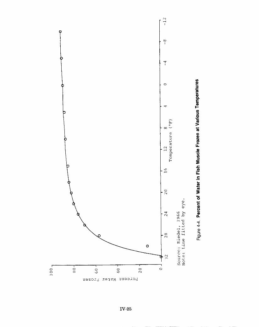
0
c Q
E .-
IV-25

The r a t e o f h e a t r e m o v a l i s a d i r e c t f u n c t i o n o f t h e
t e m p e r a t u r e d i f f e r e n c e between t h e f i s h and t h e b r i n e ; t h e g r e a t e r t h e t e m p e r a t u r e d i f f e r e n c e , t h e more r a p i d t h e c o o l i n g r a t e . The t e m p e r a t u r e of t h e b r i n e i s de t e rmined p r i m a r i l y by
t h e suc t ion pressure i n t h e c o i l s , although the f reez ing po in t of
t h e b r i n e s e t s t h e l o w e r l i m i t f o r t h e b r i n e t e m p e r a t u r e . A
d i scuss ion of t h e opera t ion of t h e r e f r i g e r a t i o n system used f o r f reez ing f i s h i s given i n Chapter 111.
During f reez ing , t h e temperature of t h e b r ine and f i s h i n a
br ined wel l decreases s t e a d i l y u n t i l a period of ' 'thermal a r r e s t ' '
o c c u r s ( F i g u r e s 4-2 and 4 - 3 ) . A t t h i s p o i n t , most of t h e w a t e r
i n t h e f i s h f r e e z e s , r e l e a s i n g t h e l a t e n t h e a t of f u s i o n . A
d i scuss ion of t h e thermal p r o p e r t i e s of f i s h , t h e reason f o r t he
p la teau i n t h e temperature graph during f reez ing , and t h e amount
of hea t removed from t h e f i s h during var ious s t ages of handling
i s g i v e n i n Appendix A. The impor t ance of r a p i d f r e e z i n g f o r
maintaining q u a l i t y i s discussed i n Chapter V.
The speed a t which a w e l l f u l l of f i s h can be f r o z e n a l s o
depends on t h e s i z e of t h e f i s h . S m a l l e r f i s h have a l a r g e r
s u r f a c e a r e a t o volume r a t i o t h a n l a r g e r f i s h and c o n s e q u e n t l y g ive up h e a t more readily--compare t h e shape of t h e broken l i n e s
a f t e r b r i n i n g i n F i g u r e 4 -2 . P a t t e r s o n and B u r n s , 1984, found
t h a t , on t h e ave rage , t h e backbone t e m p e r a t u r e of f i s h 1 0
pounds o r less reached 20°F two hours a f t e r t h e b r i n e temperature
f e l l t o 2o0F. The 40-pound or l a r g e r f i s h needed 2 9 h o u r s o f
exposure t o b r i n e a t 20°F or l e s s f o r t h e i r backbone temperature t o reach 20°F.
DRYING THE WELLS
Drying w e l l s (removing t h e b r i n e from
h a s n o t been a s t a n d a r d p r a c t i c e aboard a wel l of frozen f i s h )
most modern s e i n e r s ,
IV-26

a l t h o u g h it was a common and o f t e n n e c e s s a r y p r a c t i c e aboard
b a i t b o a t s and c o n v e r t e d p u r s e s e i n e r s d u r i n g t h e 1 9 6 0 s . The
p r a c t i c e has r ecen t ly regained popular i ty .
T h e advan tages of d r y i n g w e l l s i n c l u d e (1) a r e d u c t i o n i n t h e t i m e f i s h a r e exposed t o dense b r i n e and a consequent
r e d u c t i o n i n s a l t u p t a k e , ( 2 ) a d e c r e a s e i n t h e amount of dense
b r i n e used d u r i n g a t r i p , and t h e r e f o r e t h e amount of s a l t t h a t
m u s t be purchased, ( 3 ) an inc rease i n t h e r e f r i g e r a t i o n capac i ty a v a i l a b l e f o r o t h e r w e l l s , s i n c e d r y w e l l s r e q u i r e l e s s
r e f r i g e r a t i o n t o m a i n t a i n a g i v e n s t o r a g e t e m p e r a t u r e , ( 4 )
reduced wear on t h e c i r c u l a t o r pumps, because the pumps a r e n o t
r u n w h i l e t h e w e l l s a r e d r y , (5) l e s s l o a d on t h e a u x i l i a r y
engines because l e s s e l e c t r i c i t y i s needed t o r u n t h e c i r c u l a t o r
pumps and ammonia compressors, and ( 6 ) decreased f u e l consumption
due t o reduced demand f o r e l e c t r i c i t y and reduced weight of t h e
vessel..
U s u a l l y a l l t h e w e l l s a r e d r i e d e x c e p t f o r t h e l a s t w e l l s
f i l l e d . This a l lows b r i n e t o be saved f o r unloading and r e u s e on
t h e n e x t t r i p . The t e m p e r a t u r e i n w e l l s h e l d wet shou ld be
maintained a s l o w and wi th a s l i t t l e f l u c t u a t i o n as poss ib le . I f
t h e r e i s a d e l a y of more t h a n f i v e t o s e v e n d a y s b e f o r e
unloading, t h e wet w e l l s should be dr ied .
Of ten t h e r e f r i g e r a t i o n t o a w e l l i s s topped f o r a few h o u r s
b e f o r e pumping t h e b r i n e o u t t o a l l o w any i c e which formed on t h e
c o i l s o r bu lkheads t o m e l t . T h i s improves t h e a b i l i t y of t h e
c o i l s t o remove h e a t ( s i n c e i c e i s an i n s u l a t o r ) , and f a c i l i t a t e s
unloading. The temperature of t h e b r i n e should not increase more
than one degree during t h i s temporary r e f r i g e r a t i o n stoppage.
A w e l l should n o t be d r i e d u n t i l a l l t h e f i s h a r e f r o z e n
c o m p l e t e l y and a r e c l o s e t o e q u i l i b r i u m w i t h t h e b r i n e
IV-27

temperature. Heat cannot be removed quickly from a dry wel l due
t o t h e poor heat-conducting c h a r a c t e r i s t i c s of s tagnant a i r . To
lower the temperature of t h e f i s h d rama t i ca l ly a f t e r t h e wel l i s d r i e d , a considerable temperature d i f f e r e n c e m u s t be maintained
between the frozen f i s h and t h e ammonia c o i l s . This temperature
d i f f e r e n c e t e n d s t o cove r t h e c o i l s w i t h i c e , r educ ing t h e i r
e f f i c i e n c y , and causes dehydration of t he f i s h .
The t i m e r e q u i r e d t o f r e e z e a w e l l of f i s h and reduce t h e
t e m p e r a t u r e of t h e f i s h v a r i e s w i t h t h e s i z e of t h e w e l l , t h e
s i z e o f t h e f i s h , and t h e amount of r e f r i g e r a t i o n a p p l i e d . By
monitoring the backbone temperature of f i s h with thermocouples
and a d i g i t a l thermometer, Pa t te rson and Burns, 1984, showed t h a t
t h e i n t e r n a l t e m p e r a t u r e of f i s h c o u l d b e r e d u c e d t o l O O F a f t e r a
t o t a l of t h r e e days i n br ine . They a l s o observed t h a t f i s h were f r o z e n and t h e i r t e m p e r a t u r e s were w i t h i n 3OF of t h e b r i n e
t e m p e r a t u r e by t h e t i m e t h e b r i n e r e a c h e d l S ° F . T h e s e o b s e r v a t i o n s have been c o r r o b o r a t e d by c h i e f e n g i n e e r s who are a l s o u s i n g the rmocoup les . The f a b r i c a t i o n and u s e o f t h e
t h e r m o c o u p l e s and d i g i t a l t h e r m o m e t e r a r e d e s c r i b e d i n Appendix E .
P r i o r t o t h e use of t he rmocoup les , it was common t o h o l d
b r i n e i n a w e l l f o r an a d d i t i o n a l 7 2 h o u r s a f t e r t h e b r i n e
dropped t o t h e d e s i r e d s t o r a g e t e m p e r a t u r e b e f o r e d r y i n g t h e
w e l l . I n l i g h t o f t h e a b o v e f i n d i n g s , t h i s p r a c t i c e
u n n e c e s s a r i l y p r o l o n g s t h e t u n a ’ s exposure t o b r i n e . W e l l s can and shou ld be d r i e d a s soon a s t h e b r i n e t e m p e r a t u r e i s reduced
*
t o lo°F .
T o dry a we l l , a s much b r ine a s poss ib l e i s pumped from t h e w e l l . The b r i n e can be used i n a n o t h e r w e l l o r s t o r e d . The
small amount of b r ine remaining i n the d r i ed wel l i s allowed t o
IV-28

r u n o u t of t h e w e l l i n t o t h e p i p e a l l e y by opening t h e d r a i n
l o c a t e d i n t h e lower edge of t h e inboa rd bulkhead . When t h e
b r i n e flow s tops , t h e d ra ins a r e closed.
A s t h e b r i n e i s d r a i n i n g , t h e h a t c h a r e a should be s e a l e d and in su la t ed t o prevent spoi lage of t he f i s h d i r e c t l y below t h e
r a c k . The i n s u l a t i o n may c o n s i s t o f s h e e t s o f p l a s t i c
("Visqueen") placed over t he rack, covered with overlapping empty
s a l t sacks, and he ld down w i t h a three- inch l a y e r of loose s a l t .
Although t h i s arrangement w i l l reduce a i r movement, it is n o t as
e f f e c t i v e a s c o v e r i n g t h e r ack w i t h w a t e r p r o o f i n s u l a t i o n .
Bolting t h e hatch i n p lace , covering it with a shee t of p l a s t i c ,
and t y i n g t h e p l a s t i c down so t h a t it o v e r l a p s t h e seam b e t w e e n
t h e hatch and coaming prevents water from leaking i n t o t h e w e l l
and f u r t h e r l i m i t s a i r movement.
I f thermocouples a r e i n s t a l l e d , t he temperature of f i s h i n d r i e d w e l l s can be mon i to red d i r e c t l y . O the rwise , t h e d r a i n s
from t h e d r i e d w e l l s should be opened d a i l y f o r s e v e r a l days
f o l l o w i n g d r y i n g , and weekly t h e r e a f t e r . Any f l u i d coming o u t
should be checked f o r odor , c o l o r , and t a s t e . Off -odors and
b r i g h t r e d , o d i f e r o u s , and r o t t e n - t a s t i n g f l u i d i n d i c a t e
improperly r e f r i g e r a t e d , spo i l ing f i s h . I f t hese condi t ions a r e
found, r e b r i n e t h e w e l l immedia t e ly and h o l d it a t a s l o w a
temperature a s t h e b r ine s a l i n i t y al-lows.
During dry s torage , t h e average backbone temperature of t h e
f i s h decreases slowly, on the average 0.3OF per day (Figure 4-5).
Thus, when t h e r e f r i g e r a t i o n system i s ad jus ted a s descr ibed i n Chapter 111, t h e i n f l u x of hea t from outs ide t h e w e l l ( t h e wal l -
h e a t g a i n ) and a s m a l l amount of t h e s e n s i b l e h e a t i n t h e f i s h
a r e removed. The t e m p e r a t u r e of t h e f i s h b e n e a t h t h e r a c k does
not fol low t h i s p a t t e r n ; r a t h e r , it increases quickly by 13OF, on
IV-29
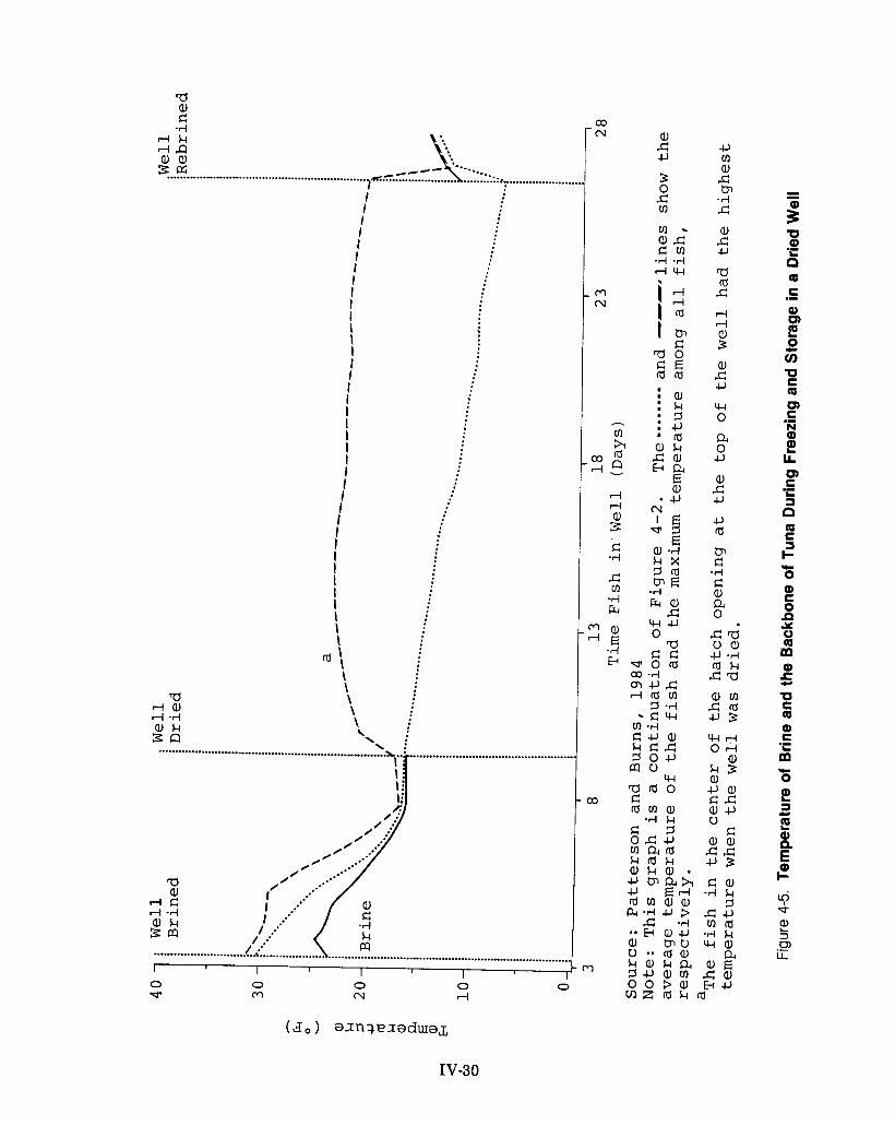
a a, c -4
r l k rlQ @ a , zffi .. .. eecc- *... ............................................................. ]": ....................... ........ ::: ...................... i
i I I I I I I I I I I I I I I I I I I I I I I I I
I I I I I I I I I I \ I \
a: \
0 v
+J rn a, c t3-l -4 c a, c c, a rd c rl rl
$ a, c c, 4-1 0
a 0 c, a, c c, +J rd
F c -4 c a, a, 0
ca u a , +J -4 rdk
a m crd 4 3 4 - 1 d 0 4
a, k 3 a, @ a , c c ac, u
c aa, cc * 3 Ca,
-A k 7 cc,
- - 5 U Q) .- b Q C
Q) 0
0
U C 0 0 C N Q)
IA 0 C
3
0 C 3 + 0 Q) C 0 P Y 0 0
Q)
U C 0 Q) C
.- E z
.- E
.- L
n
.c
m
d
.- k .c 0 Q)
3
Q)
Q) I-
L
U
E
E" $ a, 3 m LL
L
.-
IV-30

t h e a v e r a g e , a s soon a s t h e w e l l i s d r i e d , and r ema ins a t t h a t
l e v e l u n t i l rebr in ing .
A s soon a s b r i n e i s removed, t h e t e m p e r a t u r e s a long t h e
bulkheads, f l o o r , and overhead begin t o diverge (Figures 4-6 and
4-7). Surface loca t ions have been observed t o have temperatures
over45OF, e v e n t h o u g h t h e ave rage t e m p e r a t u r e i n t h e w e l l s i s a t
o r below 15OF (Pa t t e r son and B u r n s , 1984). Pos i t i ons exh ib i t i ng
t h e s e h i g h e r t e m p e r a t u r e s were l o c a t e d on bu lkheads be tween a w e l l and t h e eng ine room ( F i g u r e 4 - 6 ) , where t h e r e a r e gaps of
one f o o t o r more between ammonia c o i l s , or i n t h e midd le o f
unloading doors when the ad jacent wel l was f i l l e d w i t h sea water
(Figure 4-7). These e leva ted temperatures a r e confined t o smal l
a r eas s ince thermocouples posi t ioned on l i n e s t h a t were four t o
seven i n c h e s o f f t h e s u r f a c e by t h e s e l o c a t i o n s d i d n o t show
s i m i l a r l y e l e v a t e d t e m p e r a t u r e s , and f i s h removed from t h e s e
l o c a t i o n s showed no s i g n s of spoi lage.
The temperature of f i s h a t unloading doors i s influenced by
t h e t e m p e r a t u r e i n t h e a d j a c e n t w e l l . E l e v a t e d t e m p e r a t u r e s
(above 2 5 0 F ) a r e n o t found when t h e a d j a c e n t w e l l i s h e l d a t
300F. B y c a r e f u l l y p l a n n i n g t h e sequence i n which w e l l s a r e
f i l l e d , it i s p o s s i b l e t o e n s u r e t h a t d r i e d w e l l s a r e a lways
ad jacent t o c h i l l e d we l l s .
O n o lde r ves se l s , t h e w e l l i n s u l a t i o n may have d e t e r i o r a t e d
i n c e r t a i n s p o t s , p a r t i c u l a r l y i f i t h a s been exposed t o w a t e r
because of a l e a k . Evidence of t h i s i s e x c e s s i v e i c e f o r m a t i o n
on t h e e x t e r i o r of b u l k h e a d s , a n d / o r t h e s p o i l i n g o f f i s h l y i n g
a g a i n s t such a s p o t . I n s t a l l i n g a wooden r a c k o r m e t a l s c r e e n
( s i m i l a r t o those used on t h e unloading doors i n b a i t b o a t s ) over
t h e c o i l s i n t h i s a r e a w i l l h o l d t h e f i s h away from t h e s o u r c e of
hea t . This w i l l increase t h e i n s u l a t i o n by providing a dead a i r
space when the wel l i s d r i e d , and w i l l e l imina te t h e problem.
IV-31

a, c a a, c -4
r l k
$ 2 .......I....................... F H K Z
\ \ \
I
I I I i \ \ \ \ I I I I / I
/'
f f I I I 1 \ \ / / I i
d a , a / rl -4 / a , k 5 a '. a
z m
0 0 0 0 0 -? m CJ rl
0 0 u3 In
(,go) ainqeiaduIaL
IV-32
E
7 m a c rd
0 C 3 I- .c 0 Q) CD
0 E G
Q)
5
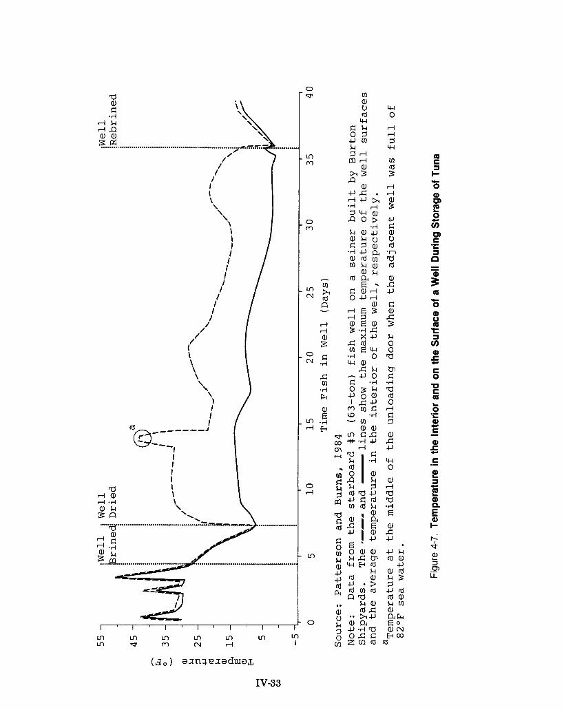
a ria, rl -4
I I i \ \ \
3 a '. ....... ................ " ..................... >.%=.m. a
Ln m m m m m m m rr m CJ rl I
If) a, u 4 - 1 m 0 w
c k rl 0 7 rl 4 J m ? k w ? r l m r l 01 s a,
IV-33

UNLOADING THE FISH
A t m o s t c a n n e r i e s t u n a a r e u n l o a d e d w i t h a b a c k b o n e
t e m p e r a t u r e of 14OF or less. T h e s a m e c o n d i t i o n i s n e c e s s a r y t o
r e c e i v e a c l e a n b i l l o f l a d i n g when t r a n s s h i p p i n g f i s h . T h i s
s i m p l i f i e s the p r e p a r a t i o n s f o r un load ing and helps t o m a i n t a i n
the q u a l i t y o f t he f i s h s i n c e t he t u n a are n o t thawed.
T h e r e i n t r o d u c t i o n o f b r i n e t o d r i e d w e l l s ( r e b r i n i n g ) i s u s u a l l y t h e f i r s t s t e p i n p r e p a r i n g t o u n l o a d . T h i s i s d o n e t o
m e l t i ce and t o a c h i e v e a un i fo rm t e m p e r a t u r e t h r o u g h o u t t he w e l l
( F i g u r e s 4-2 a n d 4 - 7 ) , t h e r e b y r e d u c i n g t h e fo rce t h e u n l o a d e r s
must apply t o separate the f i s h . T h e a v e r a g e f i s h t e m p e r a t u r e i n
a w e l l d r i e d f o r a f e w w e e k s i s b e t w e e n 4OF a n d 13OF. W e l l s
d r i e d f o r a l o n g e r t i m e g e n e r a l l y h a v e l o w e r a v e r a g e
t e m p e r a t u r e s . T h e b r i n e a d d e d d u r i n g r e b r i n i n g m u s t h a v e a
s u f f i c i e n t l y l o w f r e e z i n g p o i n t t o a v o i d fo rming ice when exposed
t o these t e m p e r a t u r e s . Consequen t ly , b r i n e w i t h a f r e e z i n g p o i n t
b e t w e e n 5OF a n d -3OF ( s a l i n i t y f r o m 1 9 t o 2 2 p e r c e n t ) i s
r e q u i r e d .
I f b r i n e w i t h t h i s c o n c e n t r a t i o n i s a v a i l a b l e it i s pumped
i n t o t h e w e l l ( s ) t o be u n l o a d e d f i r s t . U s u a l l y , e x i s t i n g b r i n e
m u s t be f o r t i f i e d w i t h m o r e s a l t , o r ' ' f r e s h " b r i n e m u s t be
p r e p a r e d i n t h e w e l l . T h e a m o u n t o f s a l t n e e d e d i s c a l c u l a t e d
b a s e d on the a s s u m p t i o n t ha t 25 p e r c e n t of the w e l l ' s c a p a c i t y i s
o c c u p i e d b y b r i n e a n d o n t h e known a m o u n t o f s a l t i n sea w a t e r o r t he a v a i l a b l e b r i n e (see the "Br in ing the W e l l " s e c t i o n ) .
I f f r e s h b r i n e i s t o be made, t h e s a l t i s dumped o n t o t h e
r a c k a n d d i s s o l v e d b y s p r a y i n g i t w i t h c l e a n sea w a t e r f r o m a
d e c k hose. A s s o o n a s s u f f i c i e n t b r i n e i s i n t h e w e l l t o a l l o w
t he c i r c u l a t o r pump t o m a i n t a i n s u c t i o n , t he b r i n e i s c i r c u l a t e d
IV-34

w h i l e t h e a d d i t i o n o f s e a w a t e r c o n t i n u e s . The f r e e z i n g
p o i n t l s a l i n i t y i s then measured with t h e sal inometer t o determine w h e t h e r enough s a l t was a d d e d , and t h e b r i n e c i r c u l a t e s un re f r ige ra t ed u n t i l t h e des i r ed temperature i s reached. Wells
gene ra l ly need t o be rebrined only 24 hours before t h i s condi t ion
i s achieved, although most w e l l s a r e rebr ined f o r a longer t ime
t o remove a s much i c e a s p o s s i b l e . S i n c e s a l t p e n e t r a t i o n does
occur d u r i n g r e b r i n i n g , t h e l e n g t h of t i m e a w e l l i s r e b r i n e d
should be k e p t t o a m i n i m u m . Although a t e m p e r a t u r e of 10°F o r
l ower cou ld be m a i n t a i n e d i n a r e b r i n e d w e l l , 1 2 O F t o 13OF i s prefer red s ince these s l i g h t l y higher temperatures f u r t h e r he lp
t o mel t i n t e r s t i t i a l i ce . Occasionally, a cannery reques ts t h a t
f i s h have temperatures between 22O and 24OF when unloaded. This
i s no longer a common p r a c t i c e s ince f i s h a t t hese temperatures
a r e more prone t o physical damage during unloading.
The o n l y d i f f e r e n c e i n t h e p rocedure used when f o r t i f y i n g
e x i s t i n g b r i n e i s t h a t t he b r i n e i s pumped d i r e c t l y i n t o t h e
d r i ed we l l , d i s so lv ing t h e added s a l t a s it c i r c u l a t e s .
I n a t r a d i t i o n a l u n l o a d i n g t h e b r i n e i s pumped o u t of a w e 1 1
and t h e hand expansion va lves a r e turned o f f an hour o r so before
t h e s t a r t of unloading. I f a wel l i s not packed too t i g h t l y , and
t h e s a l i n i t y of t h e b r i n e used f o r b r in ing and rebr in ing and t h e
t e m p e r a t u r e i n t h e w e l l a r e p r o p e r l y a d j u s t e d , t h e u n l o a d e r s
should be a b l e t o "hook" t h e f i s h l o o s e from t h e mass of f r o z e n
f i s h . Removing t h e t o p l a y e r of f i s h from a w e l l p r i o r t o
r e b r i n i n g c a n i m p r o v e t h e e a s e o f u n l o a d i n g b e c a u s e t h e
a d d i t i o n a l space p rov ided a l l o w s t h e r ema in ing mass of f i s h t o
sepa ra t e .
Vessel t r i m i s a f f e c t e d i f one o f a p a i r o f w e l l s i s
unloaded more r a p i d l y . T h i s i s c o r r e c t e d by moving b r i n e , i f
IV-35
poss ib l e , o r concentrat ing a l l t he unloading e f f o r t i n t h e f u l l e r wel l .
O f t e n f i s h a r e unloaded by t h e " f l o a t i n g o f f " method when
t h e y a r e t o be t r a n s s h i p p e d . Under t h i s p rocedure t h e b r i n e i s
l e f t i n t h e w e l l d u r i n g unloading . A s soon a s i n d i v i d u a l f i s h
sepa ra t e from t h e mass of f i s h they f l o a t t o t h e top of the we l l
s i n c e t h e b r i n e h a s a g r e a t e r s p e c i f i c g r a v i t y t h a n t h e f i s h .
Long-handled hooks a r e used t o s e p a r a t e t h e f i s h . The f l o a t i n g
f i s h a r e t a k e n o u t of t h e coaming and p u t i n c a r g o n e t s , which
a r e h o i s t e d i n t o t h e h o l d o f t h e r e f r i g e r a t e d c a r g o s h i p . A s
f i s h a r e removed, t h e b r i n e l e v e l d rops and more b r i n e i s added
from t h e b r i n e r ep len i sh ( o r t ransshipping) l i n e s which r u n along
t h e overhead of t h e wet deck. By t h e t i m e a w e l l i s empt i ed of
f i s h it i s fu l l - of b r i n e . To have a s u f f i c i e n t s u p p l y , b r i n e
m u s t be made up i n t h r e e d r i ed we l l s f o r every well t h a t will. be
f loa t ed o f f during t h e f i r s t day of unloading.
The e a s e w i t h which t h e f i s h f l o a t o f f can be i n c r e a s e d by
l o o s e n i n g t h e upper l a y e r of f i s h . T h i s i s done by pumping o f f
t h e b r i n e a f t e r a day o r so of r e b r i n i n g , removing t h e r ack and
m a n u a l l y " h o o k i n g " a p a r t t h e f i s h on t h e t o p o f t h e w e l l
( i n c l u d i n g t h e f i s h under t h e ove rhead) . Br ine i s t h e n readded
and c i r c u l a t e d overnight .
O c c a s i o n a l l y , d r i e d w e l l s a r e unloaded w i t h o u t r e b r i n i n g .
T h i s r e d u c e s t h e l e n g t h o f t i m e t h e f i s h a r e exposed t o b r i n e and
t h e r e f o r e l i m i t s t h e amount of s a l t up take . I n t h e absence of
rebr in ing , separa t ing t h e f i s h i s d i f f i c u l t un less t h e packing,
b r i n e c o n c e n t r a t i o n , and t e m p e r a t u r e i n t h e w e l l a r e c a r e f u l l y monitored. I f excessive fo rce (causing s i g n i f i c a n t damage t o t h e
f i s h ) and t ime a r e necessary w i t h t h i s procedure, t h e w e l l ( s ) can
always be rebrined, although t h i s p r a c t i c e may delay unloading.
IV-36
CHAPTER V TUNA QUALITY CHANGES
GENERAL DESCRIPTION
When a fish dies, its tissues begin to deteriorate due to the combined effects of bacteria, enzymes, naturally occurring chemical reactions, and other chemical and physical conditions present. The speed at which this deterioration occurs depends upon the temperature, the physical condition of the fish (age, sex, spawning condition, nutritional state, etc.), the type and number of bacteria in and on the fish, and the type and concentration of chemicals surrounding the fish. The goal of at- sea fish handling and preservation procedures is to prevent and/or minimize changes in fish quality until the fish are delivered for sale and processing. Because many factors interact and because the chemistry of fish muscle tissue is complex, the exact nature of the quality changes is not fully understood nor can the condition of preserved fish be precisely predicted. It is possible, however, to describe generally the changes in fish muscle which can occur during handling and evaluate the resulting fish quality.
BIOLOGICAL EFFECTS
The muscle tissue of living tuna is sterile (free of bacteria); however, many types of bacteria inhabit the outer surface of the skin, the gills, and the digestive tract. At death, fish lose the natural defense mechanisms that limit bacterial growth, and the number of bacteria increases rapidly-- the bacteria count doubles every 30 minutes at 80°F. These bacteria invade the fish tissue and initially attack simple nitrogen-containing compounds, producing a variety of
v-1
decomposition products, some of which are toxic and/or foul- smelling. Reducing the temperature to 29OF substantially slows bacteria growth, although a temperature of 25OF is required to completely stop replication, and bacterial enzymes continue to be active above 1 8 O F .
Autolysis, or "self-digestion," is the breakdown of tissue by the fish's own enzymes. When the fish dies, enzyme control is lost and the intestinal lining and skin are broken down, facilitating the movement of bacteria into the muscle. Since the amount of these enzymes is limited, they normally play a lesser role in decomposition than rapidly multiplying bacteria. However, at elevated temperatures ( 9 0 ° F or above), the enzymes can cause significant tissue breakdown--given enough time--even when no bacteria are present.
Histamine --
An amino acid called "histidine" is present in all species of tuna. Its breakdown by certain types of bacteria produces the organic compound ''histarnine." High levels of histamine in tuna have been associated with decomposition and outbreaks of a type of food poisoning known as scombroid fish poisoning. People who have eaten tuna with sufficiently high levels of histamine report nausea, cramps, oral blistering and burning sensation, hot flashes, rash with hives, diarrhea, vomiting, and heart palpitations.
Live tuna contain less than 0.1 milligram (mg) of histamine per 100 grams of fish (0.1 mg percent). The F D A considers a histamine level of 2 0 mg percent an indication of substantial decomposition and 50 mg percent a potential health hazard. In
1 9 8 2 , the FDA indicated that regulatory action would be taken
v-2

a g a i n s t c a n n e d t u n a c o n t a i n i n g 2 0 mg p e r c e n t o r more o f
his tamine. The FDA w i l l a l s o consider regula tory ac t ion a g a i n s t
t u n a w i t h 10 t o 2 0 mg p e r c e n t of h i s t a m i n e , when a second
i n d i c a t o r of decompos i t ion ( s p o i l a g e o d o r s o r honeycombing) i s
present . Tuna canners rou t ine ly monitor t h e h is tamine l e v e l i n raw f i s h and canned p r o d u c t . Canned t u n a c o n t a i n s , on t h e
average, l e s s than 2 m g percent of his tamine.
The r a t e o f h i s t a m i n e f o r m a t i o n i s d i r e c t l y dependent on
t e m p e r a t u r e . The r a t e i s h i g h e s t around 95OF and d e c r e a s e s
markedly below 50°F. Histamine formation a c c e l e r a t e s wi th t ime; thus more his tamine is formed during t h e l a s t hour of exposure t o
high temperature than t h e f i r s t . Histamine f i r s t appears i n t h e
a n t e r i o r p o r t i o n ( d i r e c t l y behind t h e g i l l s ) of t h e l o i n s and
remains h ighes t a t t h a t loca t ion . A s decomposition progresses ,
h i s tamine i s formed throughout t h e muscle t i s s u e .
F i g u r e 5-1 shows t h e r a t e of h i s t a m i n e f o r m a t i o n i n t h e
a n t e r i o r p a r t of s k i p j a c k under e x p e r i m e n t a l c o n d i t i o n s , a s
observed by d i f f e r e n t i nves t iga to r s . The d i f f e r e n c e s among t h e
g r a p h s and t h e ex t r eme v a r i a t i o n ( a s much a s 7 7 p e r c e n t ) i n h i s tamine c o n t e n t observed i n f i s h exposed t o t h e same condi t ions
shows t h a t t hese graphs cannot be accu ra t e ly used t o p r e d i c t t he
h is tamine concentrat ion i n f i s h exposed t o s p e c i f i c condi t ions .
The v a r i a t i o n s i n t h e g r a p h s and i n t h e h i s t a m i n e d a t a can be
e x p l a i n e d by t h e f a c t t h a t s e v e r a l t y p e s of h i s t a m i n e - f o r m i n g
b a c t e r i a have been i d e n t i f i e d , and each p robab ly produces
h is tamine a t a d i f f e r e n t r a t e and responds d i f f e r e n t l y t o changes
i n t e m p e r a t u r e . The g r a p h s show t h a t f i s h h e l d i n s e a w a t e r ove r
s i x hours may have unacceptably high l e v e l s of h i s tamine and t h a t
t h i s l e v e l can i n c r e a s e d r a m a t i c a l l y i n a s h o r t t i m e . A t t h e
same t i m e , t h e s e r e s u l t s d o n o t e n s u r e t h a t t u n a h e l d a t e l e v a t e d
temperature f o r l e s s than s i x hours w i l l have acceptable l e v e l s
of his tamine.
v-3

700
600
o 85OF Sea Water, P a t t e r s o n and Burns, 1984
85OF Sea Water, Frank e t a l . , 1983
x lOOOF Sea Water
.- I I - -I Id'
a / /
I I I
0 4 8 I I I i
1 2 1 6 2 0 2 4 T i m e i n Sea Water (Hours)
Source : P a t t e r s o n and Burns , 1984; Frank e t a l . , 1983; and Frank e t a l . , 1981.
Figure 5-1. Histamine Content of Tuna by Time Held in Sea Water
V-4

The temperature of the f i s h should be reduced a s quickly a s
poss ib l e t o minimize h is tamine formation. Under normal handl ing
c o n d i t i o n s , a t e m p e r a t u r e of 29OF i s s u f f i c i e n t t o p r e v e n t
a p p r e c i a b l e h i s t a m i n e . D u r i n g p e r i o d s o f r a p i d g r o w t h ,
histamine-forming b a c t e r i a produce l a r g e amounts of t he enzymes
t h a t change h i s t i d i n e i n t o his tamine. Because experiments have
shown t h a t a temperature below 18OF i s needed t o i n a c t i v a t e these enzymes, t h e temperature of tuna exposed t o high temperatures
f o r a pro longed t i m e should be reduced t o below 15OF a s q u i c k l y
a s poss ib le .
Honeycomb
Honeycomb i s a c o n d i t i o n produced by t h e breakdown of t h e
connective t i s s u e t h a t holds t h e muscle t i s s u e of tuna toge ther .
Although t h e e x a c t c a u s e ( s ) of t h i s breakdown h a s n o t been
i d e n t i f i e d , a u t o l y t i c enzymes and b a c t e r i a have been impl ica ted .
Honeycomb i s c h a r a c t e r i z e d by a p i t t i n g of t h e muscle t h a t
a p p e a r s o n l y i n cooked (o r precooked) f i s h . The e x t e n t o f
p i t t i n g can v a r y g r e a t l y and f l e s h w i t h e x t e n s i v e p i t t i n g
r e s e m b l e s a honeycomb. Honeycomb i s r ecogn ized by t h e canning
i n d u s t r y and r e g u l a t o r y a g e n c i e s as a v i s u a l i n d i c a t i o n of
decompos i t ion . Honeycomb i s u s u a l l y ( b u t n o t n e c e s s a r i l y )
a s s o c i a t e d w i t h h i g h l e v e l s of h i s t a m i n e and o t h e r s i g n s of
decreased q u a l i t y .
Honeycomb formation occurs most r ap id ly a t 90°F. The r a t e
decreases s i g n i f i c a n t l y below 75OF. Honeycomb g e n e r a l l y f i r s t
a p p e a r s i n t h e a n t e r i o r p a r t of t h e muscle t i s s u e c l o s e t o t h e
g i l l s , a l t h o u g h i t may a l s o appea r i n t h e p o s t e r i o r ( t a i l - e n d ) p a r t of t he l o i n a t t he same time.
Figure 5-2 shows the average honeycomb score f o r tuna he ld
i n s e a w a t e r a t 76OF, 83OF, and 90°F, f o r a g i v e n t i m e under
v-5

a c
a, k
U m Q E 0 u h a, c 0 5
a,
rb k a, > 6
0 6C
40
20
0
E x t e n s i v e
Moderate t o E x t e n s i v e
0
?'
. . . . :0 7
4 , / : .
* . .
,o 0
x = 76OF Sea PJater
o = 83'F S e a Water
A = go'l? Sea Water
1 I I I I I I I
0 4 8 12 16 20 2 4 28 T i m e i n Sea Water ( H o u r s )
S o u r c e : F a t t e r s o n a n d B u r n s , 1 9 8 4 ; F r a n k e t al., 1 9 8 1 ; O t s u , 1 9 5 7 .
Figure 5-2. Honeycomb Scores of Tuna by Time Held in Sea Water
V-6
experimental condi t ions. These scores a r e based on a 100-point
s c a l e i n which 0 i n d i c a t e s no honeycombing, and 1 0 0 e x t e n s i v e honeycombing. The s c a l e was d e r i v e d by P a t t e r s o n and B u r n s ,
1 9 8 4 , t o p e r m i t t h e c o m p a r i s o n o f r e s u l t s o f d i f f e r e n t
i n v e s t i g a t o r s u s i n g d i f f e r e n t s c a l e s . S t r a i g h t l i n e s were
connec ted t o t h e d a t a p o i n t s t o i n d i c a t e t h e g e n e r a l t r e n d o f
honeycomb f o r m a t i o n u n d e r v a r y i n g t i m e and t e m p e r a t u r e
c o n d i t i o n s . If d a t a were a v a i l a b l e , t h e t r e n d f o r 90°F would
probably show no honeycombing during an i n i t i a l per iod, followed by a r a p i d i n c r e a s e . These g r a p h s show a g e n e r a l t r e n d , b u t
should not be used t o p r e d i c t t h e condi t ion of tuna a f t e r a given
t i m e a t e l e v a t e d t e m p e r a t u r e s because (1) each expe r imen t was
conducted d i f f e r e n t l y , ( 2 ) d a t a were c o l l e c t e d under non-
commercial c o n d i t i o n s , ( 3 ) t h e e s t i m a t e s of t h e amount of
honeycombing may n o t be comparable among t h e g r a p h s , and ( 4 )
o the r f a c t o r s , not present i n t hese s t u d i e s , may a f f e c t t h e r a t e
of honeycomb formation.
F i g u r e 5-2 d e m o n s t r a t e s t h a t (1) t h e amount of honeycomb
i n c r e a s e s d r a m a t i c a l l y a f t e r 8 t o 1 2 h o u r s of exposure t o
e l e v a t e d t e m p e r a t u r e s , and ( 2 ) t h e lower t h e t e m p e r a t u r e , t h e
l o n g e r t h e t i m e b e f o r e honeycombing a p p e a r s . To p r e v e n t
honeycombing, f i s h should be c h i l l e d and f r o z e n a s soon a s
poss ib le . Because r egu la t ions p r o h i b i t t h e canning of f i s h wi th
any honeycomb, f i s h should be checked f requent ly a f t e r s i x hours
of unre f r ige ra t ed holding (see Chapter IV).
Of f-Colors
"Green" t u n a and " c a r a m e l i z e d " t u n a a r e t w o c o n d i t i o n s
o c c a s i o n a l l y found d u r i n g t h e p r o c e s s i n g of t u n a which had
r e c e i v e d s a t i s f a c t o r y h a n d l i n g . Green t u n a assumes a t a n n i s h -
g r e e n c o l o r a f t e r precooking o r r e t o r t i n g . Caramel ized t u n a
v-7

develops an orange t o brown co lo r , a caramel-l ike odor, and sweet
t a s t e during precooking.
Greening i s a s s o c i a t e d w i t h h i g h l e v e l s of t r i m e t h y l a m i n e
oxide (TMAO), a compound usua l ly found i n low concentrat ions i n t u n a . Reducing a g e n t s ( s u c h a s t h e amino a c i d c y s t e i n e ) i n t h e
p r e s e n c e o f metmyoglobin ( a muscle p igment ) and TMAO produce a
g r e e n p igment a f t e r h e a t i n g . I t i s s u s p e c t e d t h a t "green" tuna
have consumed food with an unusually high concentrat ion of TMAO.
C a r a m e l i z a t i o n i s p o s s i b l y due t o t h e r e a c t i o n between h i g h
l e v e l s of r i bose sugar and amines ( a breakdown product of amino
a c i d s ) , a l t h o u g h t h e r e a s o n some t u n a c o n t a i n abnorma l ly h i g h
l e v e l s of r i bose i s not known.
Nei ther of t hese condi t ions occurs r egu la r ly i n purse seine-
caugh t t u n a . I t i s t h e r e f o r e u n l i k e l y t h a t t h e o c c u r r e n c e of
t hese of f -co lors i s r e l a t e d t o normal handling and preserva t ion
p r a c t i c e s .
EFFECTS OF FREEZING
B r i n e immersion f reez ing and cold s to rage l i m i t t h e e f f e c t s
o f b a c t e r i a l a c t i o n and a u t o l y s i s on t h e q u a l i t y of t h e tuna .
However, c h i l l i n g and f r e e z i n g t u n a i n s e a w a t e r and b r i n e
produce o t h e r changes i n muscle t i s s u e . A d d i t i o n a l l y , t h e complex compounds t h a t compose muscle n a t u r a l l y break down i n t o
s m a l l e r , l e s s complex, and l e s s d e s i r a b l e compounds d u r i n g
prolonged frozen s torage .
S a l t Pene t ra t ion
S a l t p e n e t r a t i o n o c c u r s a s a r e s u l t of t h e d i f f e r e n c e
between t h e s a l i n i t y of t u n a ( 0 . 2 5 p e r c e n t i n l i v i n g f i s h ) and
V -8

t h a t of t h e sea water , RSW, o r b r i n e i n which it i s s tored . S a l t
up take o c c u r s when f i s h a r e immersed i n a s o l u t i o n of g r e a t e r s a l i n i t y , r e g a r d l e s s of t h e s t a t e ( f r o z e n o r u n f r o z e n ) of t h e
f l e sh . Figure 5-3 shows t h a t t h e r e l a t i o n s h i p between t h e s a l t
content of tuna and t h e t ime he ld i n b r ine i s c u r v i l i n e a r wi th a
r a p i d up take of s a l t d u r i n g t h e i n i t i a l exposure , f o l l o w e d by a
gradual slowing i n s a l t pickup. The da ta were obtained from four
t o seven-pound tuna i n good physical condi t ion t h a t were s to red
l e s s than four days i n RSW.
A s s a l t p e n e t r a t i o n p r o g r e s s e s , t h e s a l t c o n t e n t of t h e
o u t e r m o s t l a y e r o f m u s c l e i n c r e a s e s d r a m a t i c a l l y , w h i l e
s u c c e s s i v e i n n e r l a y e r s show d e c r e a s i n g l y s m a l l e r i n c r e a s e s .
Because l a r g e f i s h have l e s s s u r f a c e a r e a p e r pound t h a n s m a l l
f i s h , t h e i r s a l t content per pound i s usua l ly lower than t h a t of
small f i s h exposed t o t h e same condi t ions.
The r a t e of s a l t up take i n c r e a s e s w i t h (1) an i n c r e a s e i n temperature, ( 2 ) an increase i n b r ine s a l i n i t y , ( 3 ) a decrease i n
t h e amount of f r o z e n w a t e r i n t h e f i s h , and ( 4 ) any a b r a d i n g o r
s p l i t t i n g of t h e skin.
Temperature has a g r e a t e r e f f e c t on t h e r a t e of s a l t uptake
t h a n s a l i n i t y d i f f e r e n t i a l . T h e r e f o r e , l i m i t i n g t h e r i s e i n b r i n e temperature i s important when f i s h a r e stowed d i r e c t l y i n b r i n e . The r a t e of s a l t up take i s d r a m a t i c a l l y reduced when
muscle t i s s u e i s f r o z e n because f r e e z i n g r e d u c e s t h e amount o f
un f rozen w a t e r i n t h e f l e s h - - s a l t does n o t r e a d i l y d i f f u s e
through ice . The s k i n of tuna i s a b a r r i e r aga ins t s a l t ; breaks
i n t h e s k i n a l low s a l t t o e n t e r t h e f l e s h much f a s t e r .
L i m i t i n g s a l t u p t a k e i s i m p o r t a n t b e c a u s e (1) s a l t
pene t r a t ion a c c e l e r a t e s undesirable q u a l i t y changes i n co lor and
v-9

0 0
0
0 0
0
In In
0 In
In w
0 Tr
m m
h
0 h rd
0 - m
a, E: 4 k
n
a m c\1
0 N
n l l
3 -I
-I
a
v-10

t e x t u r e ( s e e below), ( 2 ) f i s h w i t h low s a l t content a r e gene ra l ly
more v a l u a b l e , and ( 3 ) p r o c e s s o r s w i l l n o t buy f i s h f o r human
consumption w i t h s a l t content above a c e r t a i n l e v e l .
P ro te in Denaturation -
A l i v i n g c e l l c o n t a i n s (among o t h e r t h i n g s ) p r o t e i n
assoc ia ted w i t h water and s a l t s uniformly d ispersed i n t he form
of a s e m i - l i q u i d g e l . During f r e e z i n g , some of t h e p r o t e i n
becomes changed i n form and funct ion (becomes denatured) a s t he
w a t e r and s a l t s d i s a s s o c i a t e from i t ( s e e "F reez ing t h e F i s h , "
Chapter I V ) . T h e amount of denatured p r o t e i n i s a f f e c t e d by t h e
r a t e of freezing--the slower t h e r a t e t h e g r e a t e r the amount of
denatured p ro te ins .
Although t h e e x a c t c a u s e ( s ) of changes i n t h e t e x t u r e of
f i s h i s n o t c o m p l e t e l y unde r s tood , ev idence i n d i c a t e s t h a t
tough o r mealy t e x t u r e may be assoc ia ted w i t h t h e dena tura t ion of
p r o t e i n .
Drip Loss
The l i q u i d r ema in ing i n t h e c e l l s a f t e r f r e e z i n g c o n t a i n s
s a l t s , undenatured p r o t e i n , and f l a v o r - c o n t a i n i n g compounds.
When t h e f l e s h i s thawed, t h i s l i q u i d e s c a p e s th rough any t e a r s
i n t h e m u s c l e c e l l membrane ( " d r i p loss"). T h i s l o s s s i g n i f i c a n t l y a f f e c t s f i s h q u a l i t y . The s l o w e r t h e r a t e of
f r e e z i n g and t h e g r e a t e r and more f r e q u e n t t h e t e m p e r a t u r e
f l u c t u a t i o n s d u r i n g f r o z e n s t o r a g e , t h e g r e a t e r t h e amount of
d r i p loss during thawing, butchering, and precooking.
Color Change -
During f r o z e n s t o r a g e , t h e p igmen t s i n t h e musc le t i s s u e
g r a d u a l l y combine w i t h oxygen, a c q u i r e a b rowni sh t i n g e , and
v-11

darken t h e co lor of t h e f l e sh . This r eac t ion occurs more quickly
a t h igher temperatures and/or i n t h e presence of s a l t .
These co lor changes a r e important because co lor i s a prime
q u a l i t y c h a r a c t e r i s t i c of canned t u n a . Consumers g e n e r a l l y
p r e f e r c a n n e d t u n a w i t h a l i g h t c o l o r and t h e FDAhas e s t a b l i s h e d
r egu la t ions governing t h e range of co lor allowed i n cans of tuna
labe led " l i g h t , " or "dark" meat.
Oxidative Rancidity
The breakdown of f a t s i n t h e p r e s e n c e of oxygen ( o x i d a t i v e
r a n c i d i t y ) produces compounds with undesirable odors and t a s t e s ,
and o f t e n t u r n s t h e s u r f a c e of t h e raw f i s h y e l l o w o r orange .
Prolonged s to rage a t temperatures above 15OF, and exposure t o a p l e n t i f u l supply of oxygen (such a s occurs i n a i r b l a s t f reez ing
and f o r c e d a i r c o l d s t o r a g e rooms) a c c e l e r a t e s t h i s p r o c e s s .
O x i d a t i v e r a n c i d i t y i s n o t n o r m a l l y a problem on board p u r s e
s e i n e r s . Tempera tu res of 10°F o r below i n d r i e d w e l l s r e d u c e s
t h e chances of ox ida t ive ranc id i ty .
EFFECTS OF HANDLING
During holding i n t h e ne t , packing of a we l l , and unloading,
f i s h may be s u b j e c t e d t o h a n d l i n g t h a t a f f e c t s t h e i r p h y s i c a l
condi t ion and con t r ibu te s t o d i s c o l o r a t i o n and s a l t pene t ra t ion .
The motion of t h e ves se l , ne t , and s k i f f can b r u i s e and chafe t h e
f i s h . Overpacking of a w e l l c a u s e s s p l i t , b roken , c rushed , and deformed f i s h . I f c rowbars a r e needed t o s e p a r a t e t h e f i s h
during unloading, some of t h e f i s h may be ruined f o r canning due
t o c u t s or ho le s made wi th t h e crowbars. Often, damage sus ta ined
during handling i s cumulative and depends on t h e t rea tment during
v-12

a preceding s tage . For example, f i s h held a long t ime i n t h e ne t
tend t o be s o f t and consequently a r e more e a s i l y damaged during
b r a i l i n g and loading t h e w e l l s . So f t f i s h pack t i g h t e r and t h i s
can lead t o o v e r f i l l e d w e l l s and unloading d i f f i c u l t i e s . Flesh
t h a t i s b r u i s e d o r exposed t o d i g e s t i v e enzymes due t o s p l i t
b e l l i e s has a darker co lor .
CONTAMINATION
Any f o r e i g n s u b s t a n c e i n a w e l l of f i s h may end up a s
contamination i n t he canned product. Consequently, w e l l s m u s t
be c l e a n e d t h o r o u g h l y b e f o r e f i s h a r e s t o r e d . Only s u b s t a n c e s
approved by t h e FDA f o r i n d i r e c t contac t wi th foods ( s a l t , b u b b l e
b u s t e r ) should be added. Some substances t h a t can cause problems
a r e fue l o i l , ammonia, copper ions, p a i n t ch ips (from improperly
p a i n t e d bu lkheads o r c o i l s ) , broken g l a s s , and c i g a r e t t e b u t t s .
The presence of any of t hese i n a can of tuna is unacceptable.
Fuel O i l
Wells used t o s t o r e f u e l o i l ( p r i o r t o s t o r i n g f i s h ) m u s t be
cleaned properly. C i r cu la to r suc t ion and discharge pipes and t h e
p o r t i o n s of t h e c o i l s n e x t t o t h e bu lkheads a r e t h e a r e a s most
f r e q u e n t l y missed d u r i n g c l e a n i n g . Wells w i t h c r a c k s i n t h e
l i n e r p l a t e s h o u l d n o t b e u s e d t o s t o r e f u e l b e c a u s e t h e
su r round ing i n s u l a t i o n may a b s o r b f u e l and s u b s e q u e n t l y c a u s e
c o n t a m i n a t i o n . Imprope r ly s e a l e d un load ing d o o r s and l e a k i n g
valves i n t h e f u e l l i n e s may a l s o cause problems.
Fuel o i l p roduces a c h a r a c t e r i s t i c odor i n f i s h . T h i s i s
most e a s i l y de tec ted a f t e r thawing o r precooking.
V-13
Ammonia
Ammonia produces a pungent odor and c a u s e s t h e precooked
f l e s h t o have a p ink o r r e d c o l o r . F i s h exposed t o ammonia--a
t o x i c substance--are unacceptable f o r human consumption.
A s soon a s ammonia i s d e t e c t e d i n a w e l l c o n t a i n i n g f i s h ,
t h e expans ion v a l v e s shou ld be s h u t o f f t o l i m i t t h e amount of
ammonia l o s t from t h e r e f r i g e r a t i o n system. The w e l l should then
b e pumped d r y , t h e con tamina ted f i s h removed, and t h e l e a k
located. Leaks commonly occur i n t h e pipe seam a t a bend i n the
c o i l o r under a hold-down clamp.
A g a s mask( s ) and a s e a w a t e r hose w i t h a fog t y p e n o z z l e
( t o wash t h e ammonia o u t of t h e a i r ) m u s t be a v a i l a b l e i n t h e
event high concent ra t ions of ammonia a r e encountered. Ammonia
shou ld be evacua ted from t h e c o i l b e f o r e r e p a i r s a r e made.
Although a permanent welded r e p a i r i s p re fe rab le , "sp lash zone"
(an epoxy-like compound) o r neoprene and some hose clamps can be
used u n t i l a permanent r e p a i r i s made.
Metal S t a i n
Copper ions have a s t rong a f f i n i t y f o r tuna muscle, and when
absorbed by t u n a , cause a b l u e o r b l a c k s t a i n t o appea r on t h e
s u r f a c e o f t h e m e a t when t h e c a n s a r e r e t o r t e d . T h i s
d i s c o l o r a t i o n does not occur during precooking b u t forms i n t he
r e d u c i n g ( l o w o x y g e n ) e n v i r o n m e n t i n s i d e t h e c a n d u r i n g
r e t o r t i n g .
The m o s t common causes of metal s t a i n a r e (1) f i t t i n g s made
o f coppe r , b r a s s , o r b ronze i n f i s h w e l l s o r t h e b r i n e t r a n s f e r system, and ( 2 ) b r ine made w i t h s a l t containing copper compounds.
V-14

T o e n s u r e s a l t w i l l n o t c a u s e t h i s problem, t h e copper c o n t e n t ( p r o v i d e d b y t h e m a n u f a c t u r e r ) s h o u l d be no m o r e t h a n 2
p a r t s per m i l l i o n ( .OOO2 p e r c e n t ) .
V-15

CHAPTER VI QUALITY EVALUATION
ORGANOLEPTIC TESTS
Organoleptic ( o r sensory) eva lua t ion employs t h e senses of
s i g h t , s m e l l , and touch t o judge t h e c o n d i t i o n of f i s h . T h i s
method i s quick, inexpensive, and provides r e l i a b l e r e s u l t s w i th
an experienced observer. I n s p i t e of many a t tempts , no chemical
t e s t h a s been found t h a t i s a s dependable a s t h e o r g a n o l e p t i c
method.
I n Table 6-1 a r e l i s t e d the c h a r a c t e r i s t i c s commonly judged
d u r i n g o r g a n o l e p t i c e v a l u a t i o n and d e s c r i p t o r s f o r d i f f e r e n t
q u a l i t y l e v e l s f o r each c h a r a c t e r i s t i c . Appearance of eyes and
s k i n and e x t e n t of p h y s i c a l damage can be checked when t h e f i s h
a r e unloaded i n a frozen condition. Other c h a r a c t e r i s t i c s can be
observed o n l y i n thawed f i s h . O r g a n o l e p t i c e v a l u a t i o n i s
normally employed t o determine whether f i s h a r e acceptable f o r
c a n n i n q , b u t n o t t o a s s i g n t h e f i s h t o v a r i o u s q u a l i t y
c l a s s i f i c a t i o n s . The e x t e n t of p h y s i c a l damage i s one f a c t o r
used by processors t o a d j u s t t h e p r i c e of raw tuna.
A f t e r p recook ing , t h e f l e s h i s checked on t h e c l e a n i n g
t a b l e s f o r honeycombing. The p r e s e n c e of any honeycomb renders t h e f i s h u n a c c e p t a b l e f o r canning and s i g n a l s t h e need t o
i n c r e a s e t h e t e s t i n g of f i s h from t h e same s e t and w e l l f o r
h i s tamine a s wel l a s honeycomb.
CHEMICAL TESTS
Laboratory t e s t s a r e used t o measure t h e s a l t and h is tamine content of samples of tuna a t unloading and a t var ious s tages of
processing. The sampling procedures a r e designed t o measure t h e
VI-1

Q C a I- 3 Q K
0 C 0
Q
.c
.- c a - s w )r
Q
c .- - 6 0
Q)
0 C Q
.- c n - P 0
Ci, a, n CTI
I-
7
-
z
E a V
a ZT: v)
;I V
4
il a 3 oi
E:
H
U
a
L
- a c c l O c o
LI x E .rl ru x rl +J ,.c m .4 d m
0 cl
4J
d a m
E .rl
w w 0
c4 r m Y
4J iii him .rl cl c
m t u arc m 7 m . 4 alp
4 J d
; m a, .4 4J
VI-2

ave rage s a l t c o n t e n t and t o d e t e c t e l e v a t e d h i s t a m i n e l e v e l s .
Fish t o be sampled should be chosen randomly from se l ec t ed p a r t s
of a w e l l and a l l should be i n t a c t p h y s i c a l l y ( n o t s p l i t o r
smashed).
F i s h t o be checked f o r s a l t a r e s e g r e g a t e d i n t o we igh t
c a t e g o r i e s and each s i z e i s t e s t e d s e p a r a t e l y because s a l t
content i s size-dependent. The f l e s h sample cu t from each f i s h
should include a complete c ros s sec t ion of the f i s h from the s k i n
t o backbone, because s a l t c o n c e n t r a t i o n d e c r e a s e s from t h e
o u t e r m o s t t o i n n e r m o s t l a y e r . Samples t a k e n from a r e q u i r e d number of f i s h of t h e same s i z e from a w e l l a r e ground up, and
t h e s a l t c o n t e n t of t h e m i x t u r e i s measured, u s u a l l y w i t h a
chloridometer. I f the s a l t content i s above a des i r ed l e v e l , the
p rocedure may be r e p e a t e d u s i n g d i f f e r e n t f i s h t o conf i rm t h e r e s u l t s .
Since elevated h is tamine l e v e l s f i r s t appear near t h e g i l l s ,
s amples f o r h i s t a m i n e a n a l y s i s shou ld come from t h e musc le of
t h i s p a r t of the f i s h . After chemical prepara t ion , a f luorometer
i s used t o measure t h e amount of h i s t a m i n e . T h i s t e c h n i q u e i s
s i m i l a r t o t h a t used by t h e FDA when checking canned product. I f
unacceptable concent ra t ions of h i s tamine a r e de tec ted , a d d i t i o n a l
samples a r e analyzed t o i d e n t i f y t h e ex ten t of t h e problem.
Elevated h is tamine may be de tec ted on t h e cleaning t a b l e s by
t h e sudden appea rance of a r ed i t c h y r a s h on t h e arms and hands
of t h e c leaners . T h i s t r i g g e r s increased t e s t i n g f o r h i s tamine
and honeycomb i n t h e l o t of f i s h t h a t i s being cleaned.
VI-3

CHAPTER VI1 THE EFFECT OF TUNA QUALITY ON VALUE
T h e q u a l i t y of r a w t u n a a t d e l i v e r y has a n e c o n o m i c i m p a c t
i n t w o ways: (1) t h e p r i c e p a i d f o r t h e f i s h a n d ( 2 ) t h e a m o u n t
( i f a n y ) o f f i s h r e j e c t e d f o r c a n n i n g . Consumer r e a c t i o n s t o poor q u a l i t y canned p r o d u c t a d v e r s e l y i n f l u e n c e s demand, sa les , and e v e n t u a l l y the pr ice paid fo r r a w f i s h .
P r i c e a n d t h e acceptab le l e v e l of q u a l i t y a l s o v a r y i n t h e
i n t e r n a t i o n a l market . T h e d e l i v e r y o f t o p - q u a l i t y f i s h e n s u r e s
access t o t h i s m a r k e t a n d a l l o w s t h e v a l u e of t h e ca t ch t o be
maximized.
C u r r e n t l y ( a n d f o r t h e p a s t f e w y e a r s ) t h e p r i c e s t r u c t u r e
f o r r a w t u n a i n c l u d e s t w o o r t h r e e c a t e g o r i e s based o n : s a l t
c o n t e n t , amount of p h y s i c a l damage, and backbone t e m p e r a t u r e when
unloaded . T h e h i g h e s t p r i ce i s p a i d f o r f i s h w i t h l o w l e v e l s o f
s a l t and no damage, un loaded a t 1 4 O ~ o r b e l o w .
Tuna i s a h e a l t h f u l , m u l t i - u s e , i n e x p e n s i v e , h i g h - p r o t e i n
food. T h e government and consumers p e r c e i v e a c o n n e c t i o n be tween
s o d i u m i n t a k e a n d h y p e r t e n s i o n ( h i g h blood p r e s s u r e ) . Most
consumers c o n s i d e r canned t u n a w i t h e x c e s s i v e s a l t u n a c c e p t a b l e
for both t a s t e and hea l th r e a s o n s .
T h e F D A w i l l s o o n r e q u i r e s o d i u m c o n t e n t t o be i n c l u d e d i n
t h e n u t r i t i o n i n f o r m a t i o n o n c a n n e d t u n a l a b e l s . Canned t u n a
w i t h a s a l t c o n t e n t m o r e t h a n 2 0 p e r c e n t above the l e v e l d e c l a r e d
on t h e l a b e l i s i n v i o l a t i o n o f f e d e r a l l a b e l i n g l a w s . B e c a u s e
the s a l t c o n t e n t o f t u n a d e l i v e r e d by U n i t e d S t a t e s p u r s e s e i n e r s
v a r i e s , t h e s o d i u m c o n t e n t o n t h e l a b e l m u s t be w e l l a b o v e t h e
a v e r a g e l e v e l t o c o m p l y w i t h t hese r e g u l a t i o n s . L i m i t i n g s a l t
VII-1

up take i n t u n a w i l l r educe t h e ave rage sodium c o n t e n t and i t s v a r i a t i o n i n t h e pack, and w i l l a l low t h e declared sodium l e v e l t o be lowered.
When poss ib l e , processors t r y t o blend f i s h t h a t a r e high i n s a l t w i t h l o w - s a l t f i s h , t o produce a pack w i t h an a c c e p t a b l e
l e v e l of s a l t . Since tuna a r e not mixed i n t o a homogeneous mass
b e f o r e cann ing ( p a r t i c u l a r l y i n t h e s o l i d pack) some h i g h - s a l t
cans a r e produced, even a f t e r blending.
Deformed or gouged f i s h r equ i r e e x t r a c leaning and produce
lower y i e l d s , consequently they command a lower p r i c e .
P r o c e s s o r s p r e f e r t o have f i s h unloaded w i t h backbone
temperatures a t o r below 14OF because t h i s reduces (1) t h e amount
of f i s h damaged d u r i n g un load ing and ( 2 ) t h e h e a t l o a d o n t h e
cannery cold s torage.
By l aw , f i s h t h a t show s i g n s of decompos i t ion ( o f f - o d o r s ,
o f f - t a s t e , honeycomb, o r e l e v a t e d l e v e l s of h i s t a m i n e ) o r c o n t a m i n a t i o n canno t b e canned. Smashed and m u t i l a t e d f i s h
produce i n f e r i o r p r o d u c t and cannot be p r o c e s s e d e f f i c i e n t l y .
Canned p r o d u c t which i s t o o s a l t y o r h a s o f f - c o l o r s ( g r e e n ,
c a r a m e l , o r m e t a l s t a i n ) i s u n a c c e p t a b l e t o c o n s u m e r s .
Consequent ly , p r o c e s s o r s w i l l n o t buy t u n a w i t h any of t h e s e
c h a r a c t e r i s t i c s .
The w e i g h t of f i s h t h a t i s u n a c c e p t a b l e f o r canning d u r i n g un load ing and b u t c h e r i n g i s deducted from t h e t o t a l amount
de l ivered . T h e amount of f i s h r e j ec t ed during f i n a l processing
(precooking, c leaning, canning) i s mul t ip l i ed by a f a c t o r of two
or t h r e e t o p a r t i a l l y compensate the cannery f o r t h e weight l o s t
and t h e c o s t s incurred i n processing t h i s f i s h .
VII-2

Fish from different wells may be put in the same storage bin during unloading. This is unavoidable when the fish are transshipped to the cannery. Later, if the fish from one of these wells are rejected, it may not be feasible to sort the fish; therefore all of it is rejected. Fish contaminated with fuel oil or ammonia may contaminate others under these circumstances.
To limit the impact of rejects on the value of a load of fish, it is necessary to detect unacceptable fish prior to final processing, and to segregate potential rejects. To facilitate the detection of unacceptable fish, cannery personnel responsible for quality testing should be informed of wells containing fish that were exposed to potentially serious quality altering conditions. These conditions include (1) wells used to store fuel, ( 2 ) wells in which an ammonia leak occurs, ( 3 ) wells with fish that were in the net for over six hours, and ( 4 ) wells in
which the temperature remained above 35OF for more than 24 hours after the addition of fish. In addition to minimizing the amount of rejects in one load of fish, supplying this information to the cannery protects the entire tuna industry and the consumer by ensuring the quality of the final product.
VII-3
CHAPTER Vlll SUMMARY
GENERAL PROCEDURES
Studies on board fishing vessels and in laboratories show that the quality of fish is best preserved by (1) minimizing the time fish are held in RSW or brine, ( 2 ) limiting the amount of fish stored in a well (not overpacking), ( 3 ) freezing as rapidly and as soon after catching as possible, and (4) storing at the lowest and most stable temperature possible. The procedures used to preserve a catch should be directed toward achievement of these conditions. Because situations vary from set to set, well to well, and trip to trip, it is impossible to give strict procedures that can be applied in a l l cases. However, the following suggested procedures (summarized from the preceding chapters) are generally applicable in a variety of situations. A
discussion of each suggestion and alternative procedures is found on
0
0
rn
the indicated pages.
REFRIGERATION SYSTEM OPERATION
Adjust expansion valves so liquid ammonia is present at the coil discharge outside the well (as indicated by the presence of frost). (Page 111-1)
Maintain the lowest suction pressure allowed by the operating limits of the compressors when chilling and freezing fish. (Page 111-5)
Use a back pressure regulator to maintain a constant
temperature in wells with cold (29OF) fish in RSW.
(Page 111-10)
VIII-1

0
0
0
U s e d i f f e r e n t s u c t i o n h e a d e r s f o r c o l d w e l l s and "ho t "
w e l l s . (Page 111-8)
PREPARATION
Thoroughly c lean w e l l s before using them f o r s t o r i n g f i s h o r
preparing RSW o r b r i n e . (Page I V - 1 )
Ma in ta in RSW a t 2 9 O i n a s many w e l l s a s p o s s i b l e .
(Page I V - 1 1 )
Prepare b r i n e with 2 3 percent s a l i n i t y and a -5OF fp i n t he
l a r g e s t p a i r of w e l l s a v a i l a b l e and h o l d t h e b r i n e a t OOF. (Pages I V - 5 , IV-6)
STOWING
B r a i l and s t o w a s quickly a s poss ib l e . (Page IV-9)
A t t he beginning of b r a i l i n g , increase r e f r i g e r a t i o n t o t h e
we l l s t h a t w i l l be used. (Page I V - 1 1 )
Move f i s h through chutes with cold RSW o r br ine.
(Page 117-11)
Stow f i s h i n t o 29OF RSW. (Page I V - 1 1 )
Top o f f well with cold RSW. (Page I V - 1 2 )
Hold f i s h i n RSW f o r no more t h a n f i v e days. A f t e r t h i s ,
b r i n e (foam) t h e w e l l s r drop t h e temperature t o 10°F and dry t h e w e l l i f a d d i t i o n a l f i s h a r e n o t r e a d i l y a v a i l a b l e . (Page I V - 1 2 )
VIII-2

When adding f i s h t o a foamed o r d r i e d w e l l p a r t i a l l y f u l l of
f i s h , r e f i l l w i t h b r i n e , add no more t h a n 1 5 t o n s of f i s h
and f reeze t h i s f i s h before adding any more. (Page I V - 1 7 )
PACKING
Pump o u t o n l y enough RSW t o a l l o w t h e a d d i t i o n of f i s h and
i n s t a l l a t i o n of t h e rack. (Page IV-20)
Add t h r e e t o f o u r b r a i l e r s of f i s h a f t e r a w e l l i s f i l l e d t o
t h e " t a i l s up" c o n d i t i o n when a n o r m a l u n l o a d i n g i s
expec ted . Add o n l y two b r a i l e r s i f f i s h w i l l be f l o a t e d
o f f . (Page IV-20)
I n w e l l s containing only l a r g e (over 50-pound) f i s h , add two
b r a i l e r s of f i s h a f t e r t a i l s up. (Page IV-20)
As soon a s t h e t e m p e r a t u r e of t h e RSW d r o p s t o 2g0F , pump it o f f and add the co ldes t b r ine a v a i l a b l e . (Page I V - 2 2 )
I f t h e b r i n e t e m p e r a t u r e r i s e s above 30°F, r e p l a c e Some of
it with colder br ine . (Page IV-14)
C h i l l b r i n e t o 10°F a s r ap id ly a s poss ib l e . (Pages V - 5 ,
v-11 )
Keep the b r ine temperature 8OF above i t s f reez ing poin t ( a s
ind ica ted by a hydrometer). (Page IV-5)
VIII-3

DRYING
0 Dry w e l l s a s soon a s t h e b r i n e t e m p e r a t u r e r e a c h e s 10°F. (Page IV-28)
0 I n s u l a t e t he hatch area i n d r ied we l l s . (Page IV-29)
UNLOADING
8 I f poss ib l e , unload without rebr in ing . (Page I V - 3 6 )
0 I f r e b r i n i n g i s n e c e s s a r y , remove t h e t o p l a y e r of f i s h
beforehand and r eb r ine f o r a t m o s t 2 4 hours . (Page IV-35)
0 Maintain a temperature of 13OF o r lower i n rebr ined wel l s .
(Page I V - 3 5 )
HANDLING F I S H FROM LONG SETS
Dead f i s h h e l d i n t r o p i c a l s e a w a t e r f o r ove r s i x h o u r s m u s t be c h i l l e d and f r o z e n w i t h o u t d e l a y t o s t o p t h e f o r m a t i o n of
his tamine and honeycomb and t o l i m i t o the r q u a l i t y changes.
A common cause f o r pro longed h o l d i n g i n t h e n e t i s l a r g e
( o v e r 1 0 0 t o n s ) s e t s i z e . Thus, when it i s most c r u c i a l t o
f r e e z e f i s h q u i c k l y , t h e h e a t l o a d i s i n c r e a s e d s i g n i f i c a n t l y .
The f o l l o w i n g p r o c e d u r e s shou ld be a p p l i e d t o w e l l s c o n t a i n i n g
f i s h with p o t e n t i a l his tamine o r honeycomb problems.
0 Stow 5 t o 1 0 t o n s l e s s f i s h t h a n normal i n t h e s e w e l l s : a f t e r t h i s f i s h i s f r o z e n and c h i l l e d t o 10°F, t o p o f f t h e
wel l wi th f i s h . (Page I V - 1 7 )
VIII-4

0 Connect w e l l s t o a s e p a r a t e s u c t i o n heade r and app ly a l l
a v a i l a b l e compressors u n t i l t h e t e m p e r a t u r e i n t h e w e l l s
d rops t o lo°F. (Pages 111-5, 111-8)
e B r i n e or foam a s soon a s t h e RSW drops t o 29OF. (Page I V - 2 2 )
e I f c o l d RSW i s n o t a v a i l a b l e f o r i n i t i a l c h i l l i n g , s tow
d i r e c t l y i n t o c o l d b r i n e . ( F i s h h e l d i n t h e n e t l e s s t h a n
s i x hour s can be stowed i n s e a w a t e r and c h i l l e d a t a s l o w e r
r a t e , while r e f r i g e r a t i o n i s focused on we l l s with p o t e n t i a l
histamine or honeycomb problems. ) (Pages IV-14, V - 5 )
0 Prevent t he b r ine temperature from r i s i n g above 30°F by (1)
replacing some of the "warm" b r ine with colder b r ine , o r ( 2 )
ad jus t ing the b u t t e r f l y valves i n t he t r a n s f e r l i n e s so t h e
b r i n e c i r c u l a t o r sys t ems of a c o l d w e l l and t h e h o t w e l l a r e
interconnected. (Page IV-14)
VIII-5

APPENDICES

APPENDIX A FUNDAMENTALS OF REFRIGERATION
A r e f r i g e r a t i o n system can only remove hea t , not "add" cold.
Heat i s a f o r m o f e n e r g y a n d c a n o n l y t r a n s f e r from one s u b s t a n c e
t o a n o t h e r . The amount of h e a t i s measured i n B r i t i s h Thermal
U n i t s ( B T U ) . One BTU r a i s e s t h e t e m p e r a t u r e of one pound of
water by 1°F. The me t r i c equiva len t i s one ki logram-calor ie , t h e
amount of h e a t required t o r a i s e t h e temperature of 1 kilogram of
w a t e r l 0 C . Convers ion f a c t o r s a r e g i v e n i n Tab le A - 1 . The
quan t i ty of h e a t i n a substance depends on (1) t h e temperature of
t h e s u b s t a n c e , ( 2 ) i t s w e i g h t , a n d ( 3 ) i t s t h e r m a l
c h a r a c t e r i s t i c s ( s p e c i f i c h e a t ) .
TEMPERATURE
Tempera ture , o r s e n s i b l e h e a t ( t h e r e l a t i v e " h o t n e s s " o r
" c o l d n e s s " o f a s u b s t a n c e ) is n o r m a l l y m e a s u r e d w i t h t h e
Fahrenheit sca le . Methods f o r converting between Fahrenheit and
c e n t i g r a d e ( C e l s i u s ) t e m p e r a t u r e s c a l e s a r e p r o v i d e d i n Figure A-1 .
S P E C I F I C HEAT
The s p e c i f i c h e a t of a s u b s t a n c e i s t h e amount of h e a t
n e c e s s a r y t o r a i s e one pound of a s u b s t a n c e 1°F. For example,
w a t e r h a s a s p e c i f i c h e a t of 1 . 0 BTU p e r pound (by d e f i n i t i o n )
w h i l e i r o n h a s a s p e c i f i c h e a t of o n l y 0 . 1 2 BTU p e r pound.
Therefore, approximately e i g h t t imes t h e amount of h e a t added t o
a pound of i r o n m u s t be a p p l i e d t o a pound of w a t e r t o produce
t h e same t e m p e r a t u r e i n c r e a s e . The amount of h e a t r e q u i r e d t o
A-1

Table A-1 . Conversion Table
UNITS TIMES EQUALS BRITISH THERMAL 0.252 KILOGRAM-CALORIES UNITS (BTU)
BTU/LB 0.556 KILOCALORIE/KILOGRAM
BTU/HOUR
CUBIC FEET
CUBIC FEET
FEET
GALLONS
0 .293 WATTS
7.480 GALLONS
0.028 CUBIC P4ETERS
0.305 METERS
3.785 LITERS
GALLONS/MINUTE 0.063 LITERS/SECOND
HORSEPOWER 2,545 BTU/HOUR
HORSEPOWER
INCHES
POUNDS
0.746 KILOWATTS
2.54 CENTIMETERS
0.454 KILOGRAMS
TONS (SHORT) 2 , 000 POUNDS
TONS (SHORT) 0.909 METRIC TONS
TONS (LONG) 2 , 240 POUNDS
TONS OF 3.517 KILOWATTS REFRIGERATION
A-2

A. Conversion Formulas B. Conversion Scale
9 5
5 9
F = (- x C) + 32
32 1 C = - x ( F -
Example for -2OC 9 5 F = (- x -2) + 32
F = -18 + 32 5
F = 28.4OF (fp of Sea Water)
Example for 14OF 5 C = 9 x ( 1 4 - 32)
5 c = - x -18 9
c = -1OOC
F C F C 350
320 160
31 300 o gl
230g 220 210z 200
1601ik70 150
Figure A-1 . Temperature Conversion Formulas and Scale
A-3

produce a g i v e n t e m p e r a t u r e change i s c a l c u l a t e d by m u l t i p l y i n g
w e i g h t t i m e s s p e c i f i c h e a t t i m e s t h e d e g r e e s o f t e m p e r a t u r e
c h a n g e . T h e s p e c i f i c h e a t s o f common f o o d s a r e l e s s t h a n 1.0 B T U / l b ; t h e s e h e a t s v a r y a b o v e a n d b e l o w t h e i r f r e e z i n g p o i n t s .
The s p e c i f i c h e a t o f t u n a above i t s f r e e z i n g p o i n t i s 0.76 B T U / l b
and b e l o w f r e e z i n g i s 0.41 B T U / l b .
LATENT HEAT
A s e c o n d t y p e of h e a t - - l a t e n t h e a t - - i s t h a t w h i c h i s a d d e d
o r r e m o v e d d u r i n g t h e p h a s e c h a n g e o f a s u b s t a n c e ( f r e e z i n g o r b o i l i n g ) . During a p h a s e change the t e m p e r a t u r e r e m a i n s c o n s t a n t
u n t i l a l l the s u b s t a n c e has c h a n g e d f o r m ( s o l i d , l i q u i d , g a s ) .
The l a t e n t h e a t of f u s i o n i s t h e h e a t i n v o l v e d i n t h e c h a n g e
f r o m a s o l i d t o a l i q u i d ( o r a l i q u i d t o a s o l i d ) . The l a t e n t
h e a t o f v a p o r i z a t i o n i s t h e h e a t i n v o l v e d i n t h e c h a n g e f r o m a
l i q u i d t o a g a s ( o r a g a s t o a l i q u i d ) .
T h e l a t e n t h e a t of f u s i o n f o r w a t e r i s 1 4 4 B T U / l b a n d t h e
l a t e n t h e a t o f v a p o r i z a t i o n i s 9 7 0 B T U / l b . T h u s , o n e pound o f
i c e a t 32OF a b s o r b s 1 4 4 B T U o f h e a t w h i l e c h a n g i n g i n t o o n e pound
of w a t e r a t 32%, and one t o n o f i c e a b s o r b s 288,000 BTU ( 2 , 0 0 0 x 144) w h i l e m e l t i n g .
A " t o n o f r e f r i g e r a t i o n " i s d e f i n e d a s t h e a m o u n t o f
r e f r i g e r a t i o n produced by one t o n of ice m e l t i n g i n 24 h o u r s . A
r e f r i g e r a t i o n sys t em w i t h a one- ton c a p a c i t y w i l l absorb 288,000
BTU i n 24 h o u r s , 12 ,000 BTU p e r h o u r (288 ,000/24) and 200 BTU p e r
m i n u t e ( 1 , 2 0 0 / 6 0 ) .
Tuna f l e s h i s composed of a b o u t 70 p e r c e n t w a t e r a n d i t s
l a t e n t h e a t o f f u s i o n i s 1 0 1 B T U / l b ( 0 . 7 ~ 1 4 4 ) . The a m o u n t of h e a t t h a t m u s t be r e m o v e d f r o m a t o n o f t u n a ( i n t e r n a l
A-4

t e m p e r a t u r e of 90°F) t o f r e e z e a n d s t o r e it a t 10°F c a n be
c a l c u l a t e d (Table A-2) . F i g u r e A-2 shows the heat removed d u r i n g
d i f f e r e n t phases of on-board s t o r a g e . A l m o s t t w i c e as much heat
i s removed d u r i n g f r e e z i n g t h a n d u r i n g t e m p e r a t u r e r e d u c t i o n .
About 1.1 t o n s o f r e f r i g e r a t i o n (311,000/288,000) must be appl ied
t o a t o n o f t u n a t o f r e e z e it a n d l o w e r i t s t e m p e r a t u r e t o 10°F. T h e l i n e t h a t shows f i s h t e m p e r a t u r e s i n F i g u r e A-2 i s s i m i l a r t o g r a p h s of t u n a t e m p e r a t u r e d u r i n g n o r m a l h a n d l i n g ( F i g u r e s 4-2
a n d 4 - 3 ) .
PRESSURE
A t u n a v e s s e l r e f r i g e r a t i o n system c o n t a i n s ammonia ( p r i m a r y
r e f r i g e r a n t ) i n t w o p h a s e s ( l i q u i d a n d v a p o r ) a t v a r i o u s
t e m p e r a t u r e s and p r e s s u r e s . When the p r e s s u r e of ammonia i n the
s y s t e m i s g r e a t e r t h a n a tmosphe r i c p r e s s u r e , it i s m e a s u r e d i n
pounds per s q u a r e i n c h ( P S I ) . T h e p r e s s u r e a t a p a r t i c u l a r p o i n t
i n a r e f r i g e r a t i o n s y s t e m i s m e a s u r e d b y a p r e s s u r e g a u g e , a n d
t he i n d i c a t e d p r e s s u r e l a b e l e d PSIG.
Gauge p r e s s u r e s h o w s the d i f f e r e n c e be tween the p r e s s u r e i n
t h e s y s t e m a n d a tmosphe r i c p r e s s u r e ( a b o u t 14.7 PSI a t sea
l e v e l ) . T h e t o t a l or a b s o l u t e p r e s s u r e (PSIA) i s f o u n d b y
a d d i n g 1 4 . 7 t o t h e g a u g e p r e s s u r e . T h u s , a t s e a l e v e l
atmospheric p r e s s u r e i s 0 PSIG and 14.7 PSIA.
T h e g a u g e s u s e d on t u n a boa t s a r e c a l l e d compound g a u g e s
b e c a u s e t h e y i n d i c a t e p r e s s u r e a b o v e a n d b e l o w a t m o s p h e r i c
p r e s s u r e . I f t h e p r e s s u r e i n t h e s y s t e m i s l e s s t h a n
atmospheric, it i s u s u a l l y measured i n ' ' i nches of vacuum." A 30- i n c h vacuum i s a p e r f e c t vacuum a t sea l e v e l - - i n t h i s case t h e
barometric p r e s s u r e i s e q u a l t o the p r e s s u r e e x e r t e d by a column
of m e r c u r y 30 i n c h e s h i g h . A 1 0 - i n c h vacuum i s 1 0 i n c h e s b e l o w
A-5

0 M
0 cy N
cy a
.
II
0 0 0
N .
X
W P
X
N W
CO N
I 0 a
D c , c a -4 Q ) N Z Q )
Q) a ) k -IF a
a, m > e o a,Q Ella
In In W
0 0 0
N 0 N
.
II
0 0 0
N .
X
rl 0 rl
c, d a c, m e 0 U
w 0
c, a Q) X
u c e o a, -4 c , m a 3 4 k
0 W b
TJ rl
II
0 0 0
N .
X
rl Tr
X
0 rl I a3 c\I
0 0 0
4 rl M
.
0 CO
rl a c, 0 E
A-6

C L n
I W
c E
1 0 0 0 0 0 t I I 1 I I I I
0 0 L n Tr
I I
N rl 0 M
0 0 0 0 07 a, I-- W
A-7
0 0 rl
0 07
0 a,
0 P
0 W
0 Ln
0 e
0 Q
0 (u
, o F i
0
a id 0 4 c, rd a, x 41 0
+J c a, u k a, PI

atmospheric pressure, or a one-third perfect vacuum. This is called a gauge pressure of 10 inches of vacuum, in spite of the contradiction of the terms pressure and vacuum. For each inch of vacuum, the absolute pressure is about 0.5 P S I (14.7/30) below atmospheric pressure. In a 10-inch vacuum the absolute pressure is 9.7 PSIA (14.7-(lOxO.S)).
INTERACTION OF PRESSURE AND TEMPERATURE
The temperature at which a liquid changes to a gas (the boiling or evaporating temperature) is directly dependent on the pressure. The greater the pressure, the higher the boiling point. This same relationship is true for the condensation temperature (the temperature at which a substance changes from a vapor to a liquid).
A substance can be made to evaporate/boil (or condense) at a wide range of temperatures by adjusting the pressure. The temperature of an evaporating substance does not change until all the liquid is converted to a vapor. The substance will absorb a quantity of heat equal to its latent heat of vaporization for each pound of vapor given off. This heat must be supplied by something else that is consequently cooled. This effect is demonstrated when rubbing alcohol is wiped on a person's hand. The alcohol absorbs heat from the skin and evaporates (boils away), cooling the skin. Boiling water absorbs heat from a flame and "cools" the flame, although this cooling is not readily observed.
A refrigeration system controls the evaporating pressure of the primary refrigerant and consequently the temperature in the system through adjustment of the pressure in the system.
A-8

PROPERTIES OF AMMONIA
Ammonia (R-717) i s t h e p r i m a r y r e f r i g e r a n t u s e d o n U n i t e d
S t a t e s t u n a s e i n e r s b e c a u s e (1) t h e r a n g e of i t s e v a p o r a t i n g
temperatures a t e a s i l y produced p r e s s u r e s i s w e l l - s u i t e d t o the
f r e e z i n g a n d s t o r i n g of t u n a , ( 2 ) i t i s r e l a t i v e l y i n e x p e n s i v e ,
a n d ( 3 ) it i s r e a d i l y a v a i l a b l e . T h e r e l a t i o n s h i p b e t w e e n
p r e s s u r e a n d e v a p o r a t i n g t e m p e r a t u r e ( o r c o n d e n s a t i o n
t e m p e r a t u r e ) f o r ammonia i s shown i n F i g u r e A - 3 a n d some i m p o r t a n t charac te r i s t ics of ammonia a re p r o v i d e d i n T a b l e A-3.
L i q u i d ammonia e v a p o r a t e s a t -28OF a t a t m o s p h e r i c p r e s s u r e , -l°F a t 1 5 PSIG, a n d 29OF a t 43.8 PSIG.
A m m o n i a i s a l s o a p o t e n t i a l l y d a n g e r o u s s u b s t a n c e .
Appendix B p r o v i d e s i n f o r m a t i o n r e g a r d i n g t he safe u s e of ammonia
and f i r s t a i d i n the e v e n t of an a c c i d e n t .
SIMPLIFIED REFRIGERATION SYSTEM
F i g u r e A - 4 shows a s i m p l e a r r a n g e m e n t f o r c o o l i n g w i t h
l i q u i d ammonia . When t h e v a l v e on t h e t a n k i s o p e n e d , l i q u i d
ammonia u n d e r p r e s s u r e e n t e r s t h e c o i l . Some o f t h e l i q u i d
ammonia i n s t a n t l y e v a p o r a t e s a n d f o r m s f l a s h g a s a t t h e v a l v e .
T h e heat r e q u i r e d t o form t h i s g a s comes from the l i q u i d ammonia,
t h u s c h i l l i n g t h e r e m a i n i n g l i q u i d t o -28OF. T h i s l i q u i d t h e n p a s s e s a l o n g t h e c o i l a b s o r b i n g h e a t , f o r m i n g v a p o r
( e v a p o r a t i n g ) , a n d , i n t h e p rocess , c h i l l i n g t h e c o i l t o n e a r l y
-28OF. The coi l i n t u r n absorbs heat and c h i l l s the s u r r o u n d i n g a i r . T h i s co i l i s c a l l e d an evaporator co i l or an evaporator and
the v a l v e i s c a l l e d an e x p a n s i o n v a l v e .
COMPLETE REFRIGERATION SYSTEM
T h e a b o v e " s y s t e m " w i l l p r o d u c e r e f r i g e r a t i o n a s l o n g a s
l i q u i d a m m o n i a i s p r e s e n t i n t h e c y l i n d e r . F o r s a f e a n d
A-9

0 0 4
0 co
0 Q
h
L-I 0 v
a, o k - 7
c, rd k a,
a, B 2
0 cv
3
3 N
I
Q C .- E E a 0
2 a E E
.c
c
% z 0 C .- c E n 0
w U C 0
2 a
E n
v) u)
C Q,
c g Q) m n E v) C 0
(P
Q,
.- c - a i 6 a, 3 a L
ii
A-10

Table A-3. Thermodynamic Properties of Ammonia
Ternp.-l Pres OF I Lb. pel
I AbsPe -58 5.93 -57 -56 -55 -54 -53 -52 -51 -50 -49 -48 -47 -46 -45 -44 -43 -42 -41 -40 -39 -3 8 -3 7 -36 -3 5 -34 -33 -32 -3 1 -3 0 -2 9 -28 -2 7 -26 -25 -2 4 -23 -22 -2 1 -2 0 -19 -1 8 -17 -16 -15 -14 -13 -12 -11 -10 - 9 - 8 - 7 - 6 - 5 - 4 - 3 - 2 - 1
6.13 6.33 6.54 6.75 6.97 7.20 7.43 7.67 7.91 8.16 8.42 8.68 8.95 9.23 9.51 9.81
10.10 10.41 10.72 11.04 11.37 11.71 12.05 12.41 12.77 13.14 13.52 13.90 14.30 14.71 15.12 15.55 15.98 16.42 16.88 17.34 17.81 18.30 18.79 19.30 19.81 20.34 20.88 21.43 21.99 22.56 23.15 23.74 24.35 24.97 25.61 26.26 2 6.92 27.59 28.28 28.98 29.69
re - ;q. In.
Gage P
18.6* 18.2* 17.8' 17.4* 17.0* 16.6* 16.2* 15.7* 15.3* 14.8* 14.3* 13.8* 13.3* 12.8* 12.2* 11.7* 11.1* 10.6* 10.0* 9.3* 8.7* 8.1* 7.4* 6.8* 6.1' 5.4* 4.7* 3.9* 3.2* 2.4* 1.61 0.8* 0.0 0.4 0.8 1.3 1.7 2.2 2.6 3.1 3.6 4.1 4.6 5.1 5.6 6.2 6.7 7.3 7 .9 8.5 9.0 9.7
10.3 10.9 11.6 12.2 12.9 13.6 14.3 15.0
Volume - Cu. Ft.
Liquid v f
0.02278
0.02288
0.02299
0.02 31 0
0.02322
0.02 333
0.02345
0.02357
0.02369
0.023 3 1
0.02393
0.02406
:r Lb. Vapor
44.73 43.37 42.05 40.79 39.56
37.24 36.15 35.09 34.06 33.08 32.12 31.20 30.31 29.45 28.62 27.82 27.04 26.29 25.56 24.86 24.18 23.53 22.89 22.27 21.68 21.10 20.54 20.00 19.48 18.97 18.48 18.00 17.54 17.09 16.66 16.24 15.83 15.43 15.05 14.68 14.32 13.97 13.62 13.29 12.97 12.66 12.36 12.06 11.78 11.50 11.23 10.97 10.71 10.47 10.23
V
38.38
9.991 9.763 9.541 9.32 6
Density - Lb. oer Cu. Ft. - (iquid l/Vf
$3.9 1
13.70
33.49
43.28
13.07
42.86
42.65
42.44
42.22
42.00
41.78
41.56
Vapor l/VE
0.02235 .02306 ,02378 ,02452 ,02528
0.02 605 ,02685 .02 766 ,02850 ,02936
0.03023 .03113 ,03205 .03299
0.03395 0.03494
,03595 ,03698 ,03804 .03912
0.04022 ,04135 .04251 ,04369 .04489
0.04613 ,04739 ,04868 ,04999 ,05134
0.0527 1 ,05411 .05555 .OS701 .OS850
0.06003 ,06158 ,06317 .Ob479 .Ob644
0.068 13 .Ob985 ,07161 .07 340 ,07522
0.07 709 .07898 ,08092 ,08289 ,08490
0.08695 .OB904 ,09117 ,09334 ,09555
0.09780 ,1001 ,1024 ,1048 ,1072
Enthalpy- Btu D e r Lb.
,iquid hf
-21.2 -20.1 -19.1 -18.0 -17.0 -15.9 - 14.8 -13.8 -12.7 -11.7 -10.6 - 9.6 - 8.5 - 7.4 - 6.4 - 5.3 - 4.3 - 3.2 - 2.1 - 1.1
0.0 1.1 2.1 3.2 4.3 5.3 6.4 7.4 8.5 9.6
10.7 11.7 12.8 13.9 14.9 16.0 17.1 18.1 19.2 20.3 21.4 22.4 23.5 24.6 25.6 26.7 27.8 28.9 30.0 31.0 32.1 33.2 34.3 35.4 36.4 37.5 38.6 39.7 40.7 41.8 -
- .atent h f g - 610.8 610.1 609.5 608.8 608.2 607.5 606.9 606.2 605.6 604.9 604.3 603.6 602.9 602.3 601.6 600.9 600.3 599.6 598.9 598.3 597.6 596.9 596.2 595.5 594.8 594.2 593.5 592.8 592.1 591.4 590.7 590.0 589.3 588.6 587.9 587.2 586.5 585.8 585.1 584.3 583.6 582.9 582.2 581.5 580.8 580.0 579.3 578.6 577.8 577.1 576.4 575.6 574.9 574.1 573.4 572.6 571.9 571.1 570.4 569.6 -
Vapor hf4
589.6 590.0 590.4 590.8 591.2 591.6 592.1 592.4 592.9 593.2 593.7 594.0 594.4 594.9 595.2 595.6 596.0 596.4 596.8 597.2 597.6 598.0 598.3 598.7 599.1 599.5 599.9 600.2 600.6 601.0 601.4 601.7 602.1 602.5 602.8 603.2 603.6 603.9 604.3 604.6 605.0 605.3 605.7 606.1 606.4 606.7 607.1 607.5 607.8 608.1 608.5 608.8 609.2 609.5 609.8 610.1 610.5 610.8 611.1 611.4 -
Entropy - Btu per (Lb.) (" R) . .
Liquid Sf
-0.051: - ,0490 - ,0464 - ,0438 - ,0412 -0.0386 - ,0360 - ,0334 - ,0307 - .@281 -0.0256 - .0230 - .0204 - .0179 -0.0153 -0.01 27 - ,0102 - ,0076 - .0051 - .0025
0.0000 ,002 5 .005 1 . OC7 6 .0101
0.0126 ,0151 ,0176 ,0201 ,0226
0.0250 ,0275 .03 00 ,0325 ,0350
0.0374 .0399 .0423 ,0448 ,0472
0.0497 ,0521 ,0545 ,0570 ,0594
0.0618 ,0642 .0666 ,0690 ,3714
0.0738 .07 62 .0786 .OB09 ,0833
0.0857 ,0880 ,0904 .092 8 ,095:
Vapor S
1.4769 1.4741 1.4713 1.4686 1.4658 1.4631 1.4604 1.4577 1.4551 1.4524 1.4497 1.4471 1.4445 1.4419 1.4393
1.4368 1.4342 1.4317 1.4292 1.4267 1.4242 1.4217 1.4193 1.4169 1.4144 1.4120 1.4096 1.4072 1.4048 1.4025 1.4001 1.3978 1.3955 1.3932 1.3909 1.3880 1.3863 1.3840 1.3818 1.3796 1.3774 1.3752 1.3729 1.3708 1.3686 1.3664 1.3443 1.3621 1.3600 1.3579 1.3558 1.3537 1.3516 1.3495 1.3474 1.3454 1.3433 1.3413 1.3393 1.3372
emp. - OF
t
-60 -59 -58 -57 -56 -55 -54 -53 -52 -51 -50 -49 -48 -47 -46 -45 -44 -43 -42 -4 1 -40 -39 -38 -37 -36 -3 5 -34 -33 -3: -31 -30 -29 -28 -27 -26 -25 -24 -23 -22 -2 1 -20 -19 -18 -17 -1 6 -1 5 -14 -13 -12 -11 -10 - 9 - 8 - 7 - 6 - 5 - 4 - 3 - 2 - 1
* Inches of mercury below one atmosphere
A-1 1

Table A-3. Thermodynamic Properties of Ammonia (continued)
Pressure - Volume - Enthalov - Entropy - Btu D e r (Lb.) (" R)
'emp. - OF
t
Temp. - OF
t
Density - Lb. D e r Cu. Ft. Cu. Ft -
Vapor hs -
611.8 612.1 612.4 612.7 613.0 613.3 613.6 613.9 614.3 614.6 614.9 615.2 615.5 615.8 616.1 61 6.3 616.6 616.9 617.2 617.5 617.8 618.0 61 8.3 618.6 618.9 6 19.1 619.4 619.7 619.9 620.2 62 0.5 620.7 621.0 621.2 621.5 621.7 622.0 622.2 622.5 622.7 623.0 623.2 623.4 623.7 623.9 624.1 62 4.4 624.6 624.8 62 5.0 62 5.2 625.5 625.7 625.9 62 6.1 62 6.3 626.5 626.7 62 6.9 627.1 -
B p e r Lb. Vapor
9.116 8.912 8.714 8.52 1 8.333 8.150 7.971 7.798 7.629 7.464 7.304 7.148 6.996 6.847 6.703 6.562 6.425 6.291 6.161 6.034 5.910 5.789 5.671 5.556 5.443 5.334 5.227 5.123 5.021 4.922
4.825 4.730 4.637 4.547 4.459 4.373 4.289 4.207 4.126 4.048 3.971 3.897 3.823 3.752 3.682 3.614 3.547 3.481 3.418 3.355 3.294 3.234 3.176 3.119 3.063 3.008 2.954 2.902 2.851 2.800
V
Lb. pe Ibsolute
P
iq. In. Gage
P
- ,iquid 1 / V f
. , Liquid
v f Liquid
hf Liquid
Sf
Vapor s c
Vapor I/vs
0 1 2 3 4 5 6 7 8 9
10 11 12 13 14 15 16 17 18 19 20 21 22 23 24 25 26 27 28 29 30 31 32 33 34 35 36 37 38 39 40 41 42 43 44 45 46 47 48 49 50 51 52 53 54 55 56 57 58 59
30.42 31.16 31.92 32.69 33.47 34.27 35.09 35.92 36.77 37.63 38.51 39.40 40.31 41.24 42.18 43.14 44.12 45.12 46.13 47.16 48.21 49.28 50.36 51.47 52.59 53.73 54.90 56.08 57.28 58.50 59.74 61.00 62.29 63.59 64.91 66.26 67.63 69.02 7 0.43 71.87 73.32 74.80 76.31 77.83 79.38 80.96 82.55 84.18 85.82 87.49 89.19 90.91 92.66 94.43 96.23 98.06 99.91
101.8 103.7 105.6
15.7 16.5 17.2 18.0 18.8 19.6 20.4 21.2 22.1 22.9 23.8 24.7 25.6 26.5 27.5 28.4 29.4 30.4 31.4 32.5 33.5 34.6 35.7 36.8 37.9 39.0 40.2 41.4 42.6 43.8 45.0 46.3 47.6 48.9 50.2 51.6 52.9 54.3 55.7 57.2 58.6 60.1 61.6 63. 1 64.7 66.3 67.9 69.5 71.1 72.8 74.5 76.2 78.0 79.7 81. 5 83.4 85.2 87.1 89.0 90.9
0.02419
0.02432
0.02446
0.02460
0.02474
0.02488
0.02503
0.02518
0.02533
0.02548
0.02564
0.02581
41.34
41.11
40.89
40.66
40.43
40.20
39.96
39.72
39.49
39.24
39.00
38.7 5
42.9 44.0 45.1 46.2 47.2 48.3 49.4 so. 5 51.6 52.7 53.8 54.9 56.0 57.1 58.2 59.2 60.3 61.4 62.5 63.6 64.7 65.8 66.9 68.0 69.1 70.2 71.3 72.4 73.5 74.6
75.7 76.8 77.9 79.0 80.1 81.2 82.3 83.4 84.6 85.7 86.8 87.9 89.0 90.1 91.2 92.3 93.5 94.6 95.7 96.8 97.9 99.1
100.2 101.3 102.4 103.5 104.7 1 OS. 8 106.9 108.1 -
568.9 568.1 567.3 566.5 565.8 565.0 564.2 563.4 562.7 561.9 561.1 560.3 559.5 558.7 557.9 557.1 556.3 555.5 554.7 553.9 553.1 552.2 551.4 550.6 549.8 548.9 548.1 547.3 546.4 545.6 544.8 543.9 543.1 542.2 541.4 540.5 539.7 538.8 537.9 537.0 536.2 535.3 534.4 533.6 532.7 531.8 530.9 530.0 529.1 528.2 527.3 526.4 525.5 524.6 523.7 522.8 521.8 520.9 520.0 519.0 -
0.0975 ,0998 . lo22 ,1045 ,1069
0.1092 ,1115 ,1138 .1162 .1185
0.1208 .1231 ,1254 ,1277 .1300
0.1323 ,1346 ,1369 .1392
0.1415 0.1437
.1460
.1483
.1505
.1528 0.1551
.1573 ,1596 .1618 .1641
0.1663 .1686 ,1708 ,1730 .1753
0.1775 ,1797 ,1819 .1841 ,1863
0.1885 ,1908 .1930 .1952 .1974
0.1996 ,201 8 ,2040 ,2062 .2083
0.2105 .2127 .2149 .2171 ,2192
0.2214 ,2236 .2257 .2279 ,2301
1.3352 1.3332 1.3312 1.3292 1.3273 1.3253 1.3234 1.3214 1.3195 1.3176 1.3157 1.3137 1,3118 1.3099 1.3081 1.3062 1.3043 1.3025 1.3006 1.2988 1.2969 1.2951 1.2933 1.2915 1.2897 1.2879 1.2861 1.2843 1.2825 1.2808 1.2790 1.2773 1.2755 1.2738 1.2721
1.2686 1.2669 1.2652 1.2635 1.2618 1.2602 1.2585 1.2568 1.2552 1.2535 1.2519 1.2502 1.2486 1.2469 1.2453 1.2437 1.2421 1.2405 1.2389 1.2373 1.2357 1.2341 1.2325 1.2310
i .2704
0.1097 ,1122 ,1148 .1174 ,1200
0.1227 .1254 ,1282 ,1311 .1340
0.1369 ,1399 ,1429 .1460 .1492
0.1524 .1556 .1590 ,1623
0.1657 0.1692
,1728 ,1763 ,1800 ,1837
0.1875 ,1913 .1952 ,1992 .2 032
0.2073 .2114 ,2156 ,2199 .2243
0.2287 ,2332 ,2377 ,2423 .2470
0.2518 .2566 .2616 ,2665 ,2716
0.2767 ,2819 .2872 ,2926 ,2981
0.3036 ,3092 ,3149 ,3207 ,3265
1.3325 .3385 ,344 6 ,3508 ,3571
0 1 2 3 4 5 6 7 8 9
10 11 12 13 14 15 16 17 18 19 20 21 22 23 24 25 26 27 28 29 30 31 32 33 34 35 36 37 38 39 40 41 42 43 44 45 46 47
49 so 51 52 53 54 55 56 57 58 59
48
A-12

Table A-3. Thermodynamic Properties of Ammonia (continued)
Temp. - OF
t
60 61 62 63 64 65 66 67 68 69 70 71 72 73 74
75 76 77 78 79 80 81 82 83 84 85 86 87 88 89 90 91 92 93 94 95 96 97 98 99
100 101 102 103 104 105 106 107 108 109 110 111 112 113 114 115 116 117 118 119 120
Pressure - Lb. p e
ibsolute P
107.6 109.6 111.6 113.6 115.7 117.8 120.0 122.1 124.3 126.5 128.8 131.1 133.4 135.7 138.1 140.5 143.0 145.4 147.9 150.5 153.0 155.6 158.3 161.0 163.7 166.4 169.2 172.0 174.8 177.7 180.6 183.6 186.6 189.6 192.7 195.8 198.9 202.1 205.3 208.6 21 1.9 215.2 218.6 222.0 225.4 228.9 232.5 236.0 239.7 243.3 247.0 250.8 254.5 258.4 262.2 266.2 270.1 274.1 278.2 282.3 286.4
q. In. Gage
P
92.9 94.9 96.9 98.9
101.0 103.1 105.3 107.4 109.6 111.8 114.1 116.4 118.7 121.0 123.4 125.8 128.3 130.7 133.2 135.8 138.3 140.9 143.6 146.3 149.0 151.7 154.5 157.3 160.1 163.0 165.9 168.9 171.9 174.9 178.0 181.1 184.2 187.4 190.6 193.9 197.2 200.5 203.9 207.3 210.7 2 14.2 217.8 221.3 225.0 228.6 232.3 236.1 239.8 243.7 247.5 251.5 255.4 259.4 263.5 267.6 271.7
Volume - Cu. Ft .
Liquid V I
0.02597
0,02614
0.02632
0.02650
0.02668
0.02687
0.02707
0.02727
0.02748
0.02769
0.02790
0.02813
0.02836
er Lb. Vapor
V
2.751 2.703 2.656 2.610 2.565 2.520 2.477 2.435 2.393 2.352 2.312 2.273 2.235 2.197 2.161 2.125 2.089 2.055 2.021 1.988 1.955 1.923 1.892 1.861 1.831 1.801 1.772 1.744 1.716 1.688 1.661 1.635 1.609 1.584 1.559 1.534 1.510 1.487 1.464 1.441 1.419 1.397 1.375 1.354 1.334 1.313 1.293 1.274 1.254 1.235 1.217 1.198 1.180 1.163 1.145 1.128 1.112 1.095 1.079 1.063 1.047
Density - Lb. per Cu. Ft.
38.50
38.25
38.00
37.74
37.48
37.21
36.94
36.67
36.40
36.12
35.84
35.55
35.26 -
Vapor l/v,
0.3635 ,3700 ,3765 ,3832 ,3899
0.3968 .4037 .4108 ,4179 ,4251
0.4325 ,4399 ,4474 ,4551 ,4628
0.47 07 ,4786 .4867 ,4949 .SO3 1
0.5115 ,5200 ,5287 ,5374
0.5462 0.5552 0.5 643 0.5735 0.5828 0.5923 0.6019 0.6116 0.6214 0.6314 0.6415 0.6517 0.6620 0.6725 0.6832 0.6939 0.7048 0.7159 0.7270 0.7384 0.7498 0.7615 0.7732 0.7852 0.7972 0.8095 0.8219 0.8344 0.8471 0.8600 0.8730 0.8862 0.8996 0.9132 0.9269 0.9408 0.9549
Enthalpy - Btu per Lb.
Liquid hf -
109.2 110.3 111.5 112.6 113.7 114.8 116.0 117.1 118.3 119.4 120.5 121.7 122.8 124.0 125.1 126.2 127.4 128.5 129.7 130.8 132.0 133.1 134.3 135.4 136.6 137.8 138.9 140.1 141.2 142.4 143.5 144.7 145.8 147.0 148.2 149.4 150.5 151.7 152.9 154.0 155.2 156.4 157.6 158.7 159.9 161.1 162.3 163.5 164.6 165.8 167.0 168.2 169.4 170.6 171.8 173.0 174.2 175.4 176.6 177.8 179.0 -
- ,atent hf?3 -
518.1 517.2 516.2 515.3 514.3 513.4 512.4 511.5 510.5 509.5 508.6 507.6 506.6 505.6 504.7 503.7 502.7 501.7 500.7 499.7 498.7 497.7 496.7 495.7 494.7 493.6 492.6 491.6 490.6 489.5 488.5 487.4 486.4 485.3 484.3 483.2 482.1 481.1 480.0 478.9 477.8 476.7 475.6 474.6 473.5 472.3 471.2 470.1 469.0 467.9 466.7 465.6 464.4 463.3 462.1 460.9 459.8 458.6 457.4 456.2 455.0
Iapor hg -
527.3 527.5 527.7 527.9 528.0 628.2 528.4 628.6 628.8 628.9 629.1 629.3 529.4 629.6 629.8 629.9 630.1 630.2 630.4 630.5 630.7 630.8 631.0 631.1 63 1.3 631.4 631.5 631.7 631.8 631.9 632.0 632.1 632.2 632.3 632.5 632.6 632.6 632.8 632.9 632.9 633.0 633.1 633.2 633.3 633.4 633.4 633.5 633.6 633.6 633.7 633.7 633.8 633.8 633.9 633.9 633.9 634.0 634.0 634.0 634.0 634.0
Entropy - Btu per (Lb.1 co R) . .
Liquid s f
0.2322 ,2344 ,2365 ,2387 ,2408
0.2430 ,245 1 ,2473 .2494 ,2515
0.2537 ,2558 ,2579 ,2601 .2622
0.2 643 .2664 ,2685 ,2706 ,2728
0.2749 .27 69 ,2791 .2812
0.2833 0.2854
,2875 ,2895 .2917 ,2937
0.295 8 ,2979 ,3000 ,3021 .3041
0.3062 ,3083 ,3104 ,3125 ,3145
0.3166 ,3187 .3207 ,3228 ,3248
0.32 69 .3289 .3310 ,3330 ,3351
0.3372 ,3392 .34 13 ,3433 .3453
0.3474 ,3495 ,3515 ,3535 ,3556
0.3576
Source: Vilter Manufacturing Corp., Milwaukee, Wisconsin
. . . Vapor
S - 1.2294 1.2278 1.2262 1.2247 1.2231 1.2216 1.2201 1.2186 1.2170 1.2155 1.2140 1.2125 1.2110 1.2095 1.2080 1.2065 1.2050 1.2035 1.2020 1.2006 1.1991 1.1976 1.1962 1.1947 1.1933 1.1918 1.1904 1.1889 1.1875 1.1860 1.1846 1.1832 1.1818 1.1804 1.1789 1.1775 1.1761 1.1747 1.1733 1.1719 1.1705 1.1691 1.1677 1.1663 1.1649 1.1635 1.1621 1.1607 1.1593 1.1580 1.1566 1.1552 1.1538 1.1524 1.1510 1.1497 1.1483 1.1469 1.1455 1.1441 1.1427
'emp. - OF
t
60 61 62 63 64 65 66 67 68 69 7 0 71 72 73 74
75 76 77 78 79 8 0 81 82 83 84 85 86 87 88 89 90 91 92 93 94 95 96 97 98 99
100 101 102 103 104 105 106 107 108 109 110 111 112 113 114 115 116 117 118 119 120
A-13

TRNK OF L /QU/O AMMAIIR
EVAPORATOR COIL 7
Figure A-4. Simplified Ammonia Refrigeration System
A-14

economica l r e f r i g e r a t i o n , ammonia shou ld n o t be l o s t t o t h e
atmosphere. By adding a condenser and compressor t o t h e system,
t h e ammonia vapor can be reclaimed by turn ing the vapor back i n t o
a l i q u i d and r e t u r n i n g it t o a r e c e i v e r . F i g u r e A - 5 i s a
schematic diagram of such a system showing t h e arrangement of t h e
components, t h e d i r e c t i o n of ammonia flow, and t h e piping.
NORMAL OPERATING CONDITIONS ON A TUNA SEINER
During normal opera t ion on a tuna s e i n e r , l i q u i d ammonia a t
180 P S I G p r e s s u r e f l o w s th rough t h e expans ion v a l v e . I t s
pressure drops t o 15 P S I G a s it e n t e r s t h e evaporator coi l . Some
of t h e l i q u i d f l a s h e s i n t o a vapor and c o o l s t h e r e s t of t he
l i q u i d t o -l°F. T h e mixture of l i q u i d and vapor moves along t h e
c o i l a b s o r b i n g h e a t u n t i l a l l t h e l i q u i d i s evapora t ed . Up t o
t h i s p o i n t , t h e t e m p e r a t u r e of t h e vapor canno t r i s e above t h e
bo i l ing p o i n t and the vapor i s c a l l e d a "sa tura ted" vapor. When
a l l t h e l i q u i d h a s e v a p o r a t e d , t h e vapor t e m p e r a t u r e can r i s e ,
p roducing a " s u p e r h e a t e d " vapor . T h e d i f f e r e n c e be tween t h e
t e m p e r a t u r e of a s u p e r h e a t e d v a p o r and i t s e v a p o r a t i n g
t e m p e r a t u r e a t t h e e x i s t i n g p r e s s u r e i s t h e amoun t of
" S u p e r h e a t . " The s u p e r h e a t e d v a p o r d i s c h a r g e d f r o m t h e
e v a p o r a t o r c o i l s i s e s t i m a t e d t o have a b o u t 2 5 d e g r e e s of
s u p e r h e a t , g i v i n g a t e m p e r a t u r e of 24OF i n t h e above example. There i s a l s o a d r o p i n p r e s s u r e of a b o u t 5 t o 1 0 P S I G f rom t h e
beginning t o the end of t h e c o i l s .
The vapor p i c k s up an a d d i t i o n a l f i v e d e g r e e s of s u p e r h e a t
a s it passes along t h e suc t ion l i n e t o t h e compressor. Here the
vapor i s compressed t o 180 P S I G . T h e mechanica l energy used i n compression is converted t o h e a t energy, r a i s i n g t h e temperature
of the vapor t o 270°F. The hot , high-pressure vapor t h e n e n t e r s
t h e condenser v i a t h e d i s c h a r g e l i n e . There , s e a w a t e r f l o w s
A-1 5

h \ \
n n
r
Figure A-5. Schematic Diagram of a Refrigeration System
A-16

o v e r p i p e s c a r r y i n g t h e vapor and c o o l s t h e vapor t o 95OF ( i t s
condensing t e m p e r a t u r e a t 180 PSIG). When t h e l a t e n t h e a t o f
v a p o r i z a t i o n i s removed, t h e vapor condenses i n t o l i q u i d form.
The l i q u i d ammonia d r a i n s t o t h e rece iver and i s ready f o r reuse.
The r e f r i g e r a t i o n sys tem i s c o n v e n i e n t l y d i v i d e d i n t o two
p a r t s . A s ammonia p a s s e s th rough t h e expans ion v a l v e t o t h e
e v a p o r a t o r c o i l and t o t h e compressor i n t a k e , t h e p r e s s u r e i s r e l a t i v e l y l o w . T h i s p o r t i o n of t h e sys tem i s c a l l e d t h e ' ' l o w
s i d e . " The r ema in ing components ( c o m p r e s s o r , condense r , and
r ece ive r ) and piping make up t h e "high s ide" of t h e system. The
high s i d e i s important f o r removal of h e a t because t h e compressor
a d d s h e a t ( t h e h e a t o f c o m p r e s s i o n ) t o t h e ammonia v a p o r
e l eva t ing i t s temperature, allowing t h e sea water flowing through
t h e condenser t o coo l i t , removing b o t h t h e h e a t of compress ion
and t h e hea t picked up from t h e f i s h wel l s .
A-17
APPENDIX B AMMONIA SAFETY INFORMATION3
WARNING PROPERTIES
Ammonia has a p e n e t r a t i n g , i n t e n s e l y p u n g e n t , s u f f o c a t i n g
o d o r , a n d i s s t r o n g l - y i r r i t a n t , so t h a t t h e r e i s l i t t l e l i k e l i -
h o o d t h a t a n y o n e w i l l v o l u n t a r i l y r e m a i n i n a s e r i o u s l y
con tamina ted a tmosphe re .
FIRE AND EXPLOSION HAZARDS -
Ammonia i s capable o f fo rming f l ammable m i x t u r e s w i t h a i r w i t h i n c e r t a i n 1 i m i t . s (16 t o 25 p e r c e n t by volume) . T h e p r e s e n c e
of o i l , or a m i x t u r e of ammonia w i t h other c o m b u s t i b l e m a t e r i a l s ,
w i l l i n c r e a s e the f i . r e h a z a r d .
The e x p l o s i o n r a n g e o f ammonia i s b roadened by a m i x t u r e o f
oxygen r e p l a c i n g a i r , and b y t e m p e r a t u r e and p r e s s u r e h i g h e r t h a n
a tmosphe r i c . C o n t a c t o f ammonia w i t h c e r t a i n o the r c h e m i c a l s
( i n c l u d i n g m e r c u r y , c h l o r i n e , i o d i n e , b r o m i n e , c a l c i u m , s i l v e r
o x i d e , o r h y p o c h l o r i t e ) c a n f o r m e x p l o s i v e compounds . M e r c u r y
i n s t r u m e n t s employed i n ammonia s e r v i c e s h o u l d n e v e r be connec ted
i n such a manner as t o p e r m i t c o n t a c t of the mercu ry w i t h l i q u i d
or g a s e o u s ammonia.
Due t o i t s n a r r o w r a n g e of f l a m m a b i l i t y a n d h i g h i g n i t i o n
t e m p e r a t u r e , ammonia does n o t g e n e r a l l y c o n s t i t u t e a f i r e h a z a r d . However , when it i!; u s e d i n process w o r k o r s t o r e d a d j a c e n t t o
f l a m m a b l e m a t e r i a l s , it m a y become i n v o l v e d i n a f i r e . Where
ammonia i s i n v o l v e d i n f i r e , w a t e r i s t h e b e s t e x t i n g u i s h i n g
medium. Ammonia i s s o l u b l e i n w a t e r a n d sp ray o r f o g - t y p e
e -- 3 . R e p r i n t e d w i t h r e v i s i o n s by p e r m i s s i o n o f C a m p b e l l I n d u s t r i e s .
B-1

s t r e a m s a r e e f f e c t i v e i n removing t h e g a s from t h e a tmosphere : t he re fo re these a r e useful i n p ro t ec t ing personnel i n approaching
a l e a k i n g v a l v e o r a break . The gas l e a k should be s h u t o f f i f
poss ib l e .
HEALTH HAZARDS
Ammonia is n o t a s y s t e m i c p o i s o n - - i t a f f e c t s o n l y t i s s u e s
d i r e c t l y exposed t o it.
Local E f f e c t s
I n h a l a t i o n of h i g h c o n c e n t r a t i o n s of ammonia produces
v i o l e n t coughing because of i t s l o c a l ac t ion on t h e r e s p i r a t o r y
t r a c t . I f rapid escape i s not poss ib le , severe lung i r r i t a t i o n ,
pulmonary edema, o r death may r e s u l t . Lower concent ra t ions cause
eye i r r i t a t i o n , l a r y n g i t i s , o r b r o n c h i t i s . Table B - 1 i s a l i s t
of t h e e f f e c t s o f v a r i o u s c o n c e n t r a t i o n s of ammonia i n t h e a i r .
Swallowing l i q u i d ammonia w i l l r e s u l t i n severe cor ros ive ac t ion
on t h e m o u t h , t h r o a t , and s t o m a c h . E x p o s u r e t o h i g h g a s
c o n c e n t r a t i o n s may cause temporary b l i n d n e s s and s e v e r e eye
damage. D i r e c t c o n t a c t w i t h l i q u i d anhydrous ammonia w i l l
immediately produce se r ious b u r n s .
Chronic Toxic i ty
Chronic i r r i t a t i o n t o the eyes, nose, and upper r e s p i r a t o r y
t r a c t may r e s u l t from r e p e a t e d exposure t o ammonia vapors . A
t h r e s h o l d l i m i t v a lue of 1 0 0 PPM i n a i r h a s been s e t by some
agencies a s t h e maximum s a f e concentrat ion f o r d a i l y eight-hour
exposure.
B-2

a 0 -4 k a, PI
a, k 3 0 0 Q X w
L z E .- Q E .-
4J u a, cl-c w
0 w rl v)
0 a k Q)
a, w
E E a Y-
c
Y- Y-
c 0 -4 4J a k -I-, c a, u c 0 u
a, k 3 m 0 a X a,
53i a , k 4 3 13 -n a ,c a - d a, k O
c a a m Da, c u 0 7 r la 0 0 k k plcl
cl m 0 E h Q
a, rl ,Q a 4J u a, 4 J * a m a c
0 k m O k aa, o a
0 m
m 0 0 0
0 0 rl
rl 0
0 0 P I 0 0 v
P 0
I v 0
0 0 0
M I 0 0 0
hl
.
.
M
I N
rl I In
B-3

SAFETY EQUIPMENT
Eye P ro tec t ion
Gas-tight goggles o r fu l l - l eng th p ro tec t ion should be worn
when h a n d l i n g ammonia where l e a k s o r s p i l l s may occur . Water
wash and water sprays should be a v a i l a b l e i n a r eas where ammonia
l eaks , s p i l l s , o r sp lashes may be encountered.
Respiratory P ro tec t ion
R e s p i r a t o r y p r o t e c t i v e e q u i p m e n t m u s t b e c a r e f u l l y
m a i n t a i n e d , i n s p e c t e d , c l e a n e d , and s t e r i l i z e d a t r e g u l a r
i n t e r v a l s , and always before and a f t e r use.
Gas masks should be of a type approved by t h e U . S . Bureau of
Mines . They shou ld be s t o r e d where t h e y a r e e a s i l y a c c e s s i b l e
and where t h e r e i s no danger of ammonia c o n t a m i n a t i n g t h e
atmosphere.
Self-contained brea th ing apparatuses t h a t permit t h e wearer
t o c a r r y a supply of oxygen o r a i r compressed i n t h e cy l inde r , o r
t h e s e l f - g e n e r a t i n g t y p e t h a t produce oxygen c h e m i c a l l y , a l l o w
t h e b e s t m o b i l i t y f o r t h e wea re r . The l e n g t h of t i m e a s e l f -
c o n t a i n e d b r e a t h i n g a p p a r a t u s p r o v i d e s p r o t e c t i o n v a r i e s
according t o the amount of a i r , oxygen, or regenerat ing ma te r i a l
c a r r i e d . Compressed oxygen shou ld n o t be used where t h e r e i s danger of contac t w i t h flammable l i q u i d s o r vapors--especially i n
c o n f i n e d s p a c e s s u c h a s t a n k s o r p i t s . A s p e c i a l t y p e of s e l f -
contained brea th ing apparatus may be used t h a t includes a small cy l inde r of compressed a i r f o r escape, b u t t h a t i s supplied wi th
a i r through an a i r l i n e f o r normal work purposes.
B -4

P o s i t i v e p r e s s u r e hose masks t h a t a r e s u p p l i e d by b lowers and requi re no i n t e r n a l l u b r i c a t i o n can be used. The wearer m u s t be a b l e t o use t h e same r o u t e f o r e x i t a s f o r e n t r a n c e and m u s t
take precaut ions t o keep the hose l i n e f r e e of entanglement. The
a i r b lower m u s t b e p l aced i n a n a r e a f r e e o f con taminan t s .
A i r l i n e masks s u p p l i e d w i t h c l e a n compressed a i r a r e
s u i t a b l e fo r use only where conditions w i l l permit s a f e escape i n c a s e o f f a i l u r e o f t h e compressed a i r supply . These masks a r e
u s u a l l y s u p p l i e d w i t h a i r t h a t i s p iped t o t h e a r e a from a
compressor . Extreme c a r e m u s t be t a k e n t o e n s u r e t h a t t h e a i r
s u p p l y i s t a k e n f rom a s a f e s o u r c e , and t h a t i t i s n o t
contaminated by o i l decomposition from inadequate cooling a t t h e
compressor . A s a f e r method i s t o use a s e p a r a t e compressor of
t he type not requir ing i n t e r n a l l ub r i ca t ion . Pressure reducing
and r e l i e f valves ( a s well a s s u i t a b l e t r a p s and f i l t e r s ) m u s t be
i n s t a l l e d a t a l l mask s t a t i o n s . A n a l t e r n a t e a r rangement
f requent ly used i s high pressure breathing a i r from standard (200
cu. f t . ) c y l i n d e r s , w i t h a demand-type v a l v e and f a c e p i e c e .
Chemical c a r t r i d g e r e s p i r a t o r s may be used t o avoid inhal ing
disagreeable b u t r e l a t i v e l y harmless concentrat ions of ammonia
vapor. These r e s p i r a t o r s , however, a r e no t recommended f o r
p ro tec t ion where tox ic q u a n t i t i e s of ammonia may be encountered.
------ Caut ion: P r o t e c t i v e creams a l o n e do n o t a f f o r d adequate
p ro tec t ion .
F I R S T A I D
Every employee should understand that direct contact
with ammonia requires the instant application of large amounts of water to the affected area.

A f t e r s e v e r e e x p o s u r e t o ammonia g a s , i t i s i m p o r t a n t t o move the p a t i e n t f rom the c o n t a m i n a t e d a r e a p rompt ly . I n case o f
c o n t a c t o f l i q u i d ammonia w i t h t h e eyes o r s k i n , i m m e d i a t e
f l u s h i n g w i t h l a r g e q u a n t i t i e s o f runn ing w a t e r i s i m p e r a t i v e .
I n a l l cases of s e v e r e i n j u r y , c a l l a p h y s i c i a n a t o n c e ,
g i v i n g h i m a complete a c c o u n t o f the a c c i d e n t .
C o n t a c t w i t h S k i n and Mucous Membranes - --
Speed i n removing ammonia f rom c o n t a c t w i t h the p a t i e n t and
i n moving t h e p a t i e n t t o a n u n c o n t a m i n a t e d atmosphere i s of
p r i m a r y impor t ance . I f s k i n c o n t a c t i s e x t e n s i v e and emergency
showers a v a i l a b l e , t h e e m p l o y e e s h o u l d g e t u n d e r t h e shower i m m e d i a t e l y . Con tamina ted c l o t h i n g and shoes s h o u l d be removed
u n d e r t h e shower. I n o t h e r i n s t a n c e s , f l u s h i n g w i t h l a r g e
a m o u n t s of r u n n i n g w a t e r s h o u l d be c o n t i n u e d f o r a t l e a s t 1 5
m i n u t e s .
Under no c o n d i t i o n s h o u l d s a l v e s o r o i n t m e n t s be a p p l i e d t o t h e s k i n o r mucous membrane b u r n s d u r i n g t h e 2 4 - h o u r p e r i o d
f o l l o w i n g the i n j u r y . - Subsequen t m e d i c a l t r e a t m e n t i s otherwise
the s a m e as for thermal b u r n s .
- - -- -- - - - - ~ I
--- ---- -- ----- -------- ----- ------ --- _---_- -__--_ -- -
C o n t a c t w i t h Eves
I f e v e n s m a l l q u a n t i t i e s o f ammonia e n t e r t h e e y e s , t h e y
s h o u l d be i r r i g a t e d i m m e d i a t e l y a n d c o p i o u s l y w i t h w a t e r f o r a minimum of 1 5 minu tes . T h e e y e l i d s s h o u l d be h e l d a p a r t d u r i n g
t h e i r r i g a t i o n t o e n s u r e the c o n t a c t o f w a t e r w i t h a l l t h e
t i s s u e s o f t h e eye s u r f a c e s a n d l i d s . A p h y s i c i a n s h o u l d be
c a l l e d a t t h e e a r l i e s t p o s s i b l e moment . A f t e r t h e f i r s t 15-
m i n u t e p e r i o d of i r r i g a t i o n , i f a p h y s i c i a n i s n o t a v a i l a b l e , the
B-6

irrigation should continue for a second period of 15 minutes. It is then permissible as a first aid measure to instill 2 or 3
drops of 0.5 percent pontocaine solution or an equally effective aqueous topical anesthetic. No oils or oily ointment should be instilled unless ordered --- I by - a physician. The employee should be sent to a physician, preferably an eye specialist, as soon as possible.
-- ---- -- ---- ----- -__ -----_ -
Taken Internally -
If liquid anhydrous ammonia has been swallowed, call a physician immediately. If the patient is conscious and able, he should drink large amounts of water to dilute the chemical. Do not induce vomiting if the patient is in shock, extreme pain, or unconscious. If vomiting begins, place the patient face down with head lower than hips; this prevents vomitus from entering the lungs and causing further injury.
Nose and Throat -
Irrigate nose and mouth with water continuously for 15 minutes. If the patient can swallow, encourage him to drink large quantities of 0.5 percent citric acid solution or lemonade.
patient. ~-
Inhalation
Exposed persons should be removed at once to an uncontaminated area. If the exposure has been to minor concentrations for a limited time, usually no treatment will be required.
B-7

When t h e r e i s severe exposure t o higher concentrat ions, and
i f oxygen apparatus i s ava i l ab le , oxygen can be administered b u t
only by a person properly t r a ined f o r such d u t y . I f the p a t i e n t
i s n o t b r e a t h i n g , an e f f e c t i v e means of a r t i f i c i a l r e s p i r a t i o n
should be i n i t i a t e d immediately. Cal l a physician.
T h e p a t i e n t should be kept comfortably warm b u t not too ho t
and s'hould be kept a t r e s t .
Asphyxiation
Where b r e a t h i n g i s weak, a d m i n i s t e r oxygen o r m i x t u r e s of carbon dioxide and oxygen containing not more than f i v e percent
carbon d i o x i d e . I t can be a d m i n i s t e r e d i n t e r m i t t e n t l y f o r
per iods of 2 minutes over a t o t a l t ime not t o exceed 1 5 m i n u t e s .
( T h i s mixture, a l ready prepared and with necessary apparatus, can
g e n e r a l l y b e o b t a i n e d from l o c a l f i r e o r p o l i c e d e p a r t m e n t s o r h o s p i t a l s . )
I f b r e a t h i n g h a s ceased , s t a r t a r t i f i c i a l r e s p i r a t i o n
immediately.
A r t i f i c i a l r e s p i r a t i o n when administered by an inexperienced
person i s d e f i n i t e l y hazardous following exposure t o ammonia, and
should be avoided where p o s s i b l e . T h e u s e of a pu lmotor i s no t
recommended because i t s v i o l e n t a c t i o n w i l l i r r i t a t e and may
s e v e r e l y i n j u r e t h e l u n g s . However, a r e s u s c i t a t o r u s e d w i t h
oxygen and operated by a t r a ined person i s recommended.
B-8

F i r s t Aid Supplies
I t i s recommended t h a t the following f i r s t a id suppl ies be
kept on board ( i n addi t ion t o emergency p ro tec t ive equipment):
0 One qua r t b o t t l e of 0 .5 percent c i t r i c acid so lu t ion
0 One pound sealed package of s t e r i l i z e d gauze
These s u p p l i e s s h o u l d be s t o r e d i n c l e a n , a c c e s s i b l e
c a b i n e t s i n a l o c a t i o n t h a t i s n o t l i k e l y t o be a f f e c t e d by an
ammonia leak.
ACTION I N THE EVENT O F A LEAK
Leak Detection
A l eak i n t he ammonia valve connections or feed l i n e s i s a t
once d e t e c t e d by odor . The e x a c t l o c a t i o n of t h e l e a k may be
d e t e c t e d by a l l o w i n g t h e fumes f rom an open b o t t l e o f
hydrochlor ic ac id ( o r from a squeeze b o t t l e of s u l f u r i c acid, o r
from an SO2 a e r o s o l c o n t a i n e r ) t o come i n c o n t a c t w i t h t h e ammonia vapor, which produces a dense, white fog. Leak de tec t ion
can a l s o be obtained with moist phenolphthalein o r l i t m u s paper,
which w i l l change color i n ammonia vapor. Phenolphthalein paper
may be obtained f r e e of charge from ammonia manufacturers o r upon
request. Sulpher t a p e r s - a r e - not -_- recommended.
I f t h e r e i s any q u e s t i o n a s t o t h e s e r i o u s n e s s of a l e a k , a
gas mask of t he type approved by the U.S. Bureau of Mines fo r use with ammonia should be worn. A l l persons not equipped with such
masks should l e a v e t h e a f f e c t e d a r e a u n t i l t h e l e a k h a s been
stopped.
B-9

I f ammonia vapor i s r e l e a s e d , t h e i r r i t a t i n g e f f e c t of t h e vapor w i l l f o r c e p e r s o n n e l t o l e a v e t h e a r e a b e f o r e t h e y have
been long exposed t o dangerous c o n c e n t r a t i o n s . I f , d e s p i t e a l l
precaut ions, a person should be trapped i n an ammonia atmosphere,
h e should b r e a t h e a s l i t t l e a s p o s s i b l e and open h i s eyes o n l y when necessary. I f no gas mask i s ava i l ab le , p a r t i a l p ro t ec t ion
may be ga ined by h o l d i n g a wet c l o t h ove r t h e nose and mouth.
S i n c e ammonia vapor i n a i r w i l l r i s e , a t r a p p e d pe r son shou ld
remain c l o s e t o t h e f l o o r t o t a k e advantage of t h e l o w e r vapor
concent ra t ions a t t h a t l e v e l .
Although ammonia i s flammable only wi th in t h e narrow l i m i t s
of 1 6 t o 2 5 p e r c e n t by volume, t h e m i x t u r e of a i r w i t h ammonia
w i l l broaden t h i s range. Therefore, every precaut ion should be
taken t o keep sources of flame o r sparks from ammonia a reas . I n
t h e e v e n t t h a t f i r e shou ld b reak o u t i n an a r e a c o n t a i n i n g
ammonia, every e f f o r t should be made t o remove po r t ab le ammonia
con ta ine r s from t h e premises. I f they cannot be removed, firemen
should be informed of t h e i r loca t ion .
When a l e a k o c c u r s i n a conges t ed a r e a where a t m o s p h e r i c
d i s s i p a t i o n i s n o t f e a s i b l e , t h e ammonia shou ld be absorbed i n
water. I f l i q u i d ammonia has been re leased , i t s high s o l u b i l i t y
i n water may be u t i l i z e d t o cont ro l t h e escape of ammonia vapor.
A p p l i c a t i o n of a l a r g e volume of w a t e r from a fog o r s p r a y n o z z l e
w i l l l e s s e n v a p o r i z a t i o n a s t h e vapor p r e s s u r e of ammonia i n
water i s much l e s s than t h a t of l i q u i d ammonia. Liquid ammonia
should n o t be n e u t r a l i z e d w i t h a c i d ; t h e h e a t g e n e r a t e d by t h e
r eac t ion may increase the fumes.
B-10

APPENDIX C SAMPLE WELL-HANDLING FORM
- WELL _I_.-
TUNA FIANDLING LOG F O R V E S S E L
- C-IIEF S K I P P E R T R I P D A T E S T O
I N C H E S FISi3 BELOW COMBING WHEN PACKED: D A T E S D R I E D T O
--- UNLOADING TEMPERATURE: ( B R I N E ) - ( T U N A ) -- -- DAYS I N B R I N E :
COMMENTS :
c-1

APPENDIX D ADJUSTING BRINE SALINITY
Leaving s o m e RSW i n a w e l l d u r i n g b r i n i n g d i l u t e s t he b r i n e ,
r e d u c i n g i t s s a l i n i t y . T h e f i n a l s a l i n i t y d e p e n d s o n t h e
s a l i n i t y o f t h e a d d e d b r i n e , t h e s a l i n i t y o f RSW ( 3 . 5 p e r c e n t ) ,
and the p e r c e n t o f each i n the w e l l .
F o r e x a m p l e , c o n s i d e r b r i n e made of 50 p e r c e n t RSW and 50
p e r c e n t b r i n e w i t h a s a l i n i t y o f 22.5 p e r c e n t . T h e s a l i n i t y o f
t he newly made b r i n e i s the w e i g h t e d a v e r a g e o f the s a l i n i t i e s of RSW a n d d e n s e b r i n e , 1 3 . 0 p e r c e n t [ ( 2 2 . 5 % x 0 . 5 0 ) + ( 3 . 5 x
0.5O)l. N o t e t h e p e r c e n t o f t h e w e l l f i l l e d by each f l u i d i s
e x p r e s s e d i n i t s d e c i m a l for in ( 5 0 % = 0 . 5 0 ) . I f t h i s b r i n e w a s a
m i x t u r e o f 60 p e r c e n t d e n s e b r i n e a n d 4 0 p e r c e n t RSW, i t s
s a l i n i t y w o u l d be 14 .9 p e r c e n t [ ( 2 2 . 5 % x 0 . 6 0 ) + (3 .58 x 0.4O)l.
I t i s m o r e u s e f u l . t o c a l c u l a t e t h e p e r c e n t o f t h e f l u i d
t h a t m u s t be d e n s e b r i n e t o f o r m b r i n e w i t h a d e s i r e d s a l i n i t y .
When RSW i s r e p l a c e d w i t h d e n s e b r i n e , t h e f o l l o w i n g e q u a t i o n
appl ies :
I f a S a l i n i t y Of 1 7 p e r c e n t (g0F, f p ) i s r e q u i r e d i n a w s l l . c o n t a i n i n g RSW mixed w i t h 22.5 p e r c e n t s a l i n i t y b r i n e , t h e n :
(17.0% - 3.5%) X 100 13.5 X 100 = 71.0 p e r c e n t o f t he f l u i d i n (22 .5% - 3 . 5 % ) 19.0 the w e l l must be d e n s e b r i n e .
D-1

S e v e r a l methods can be used f o r e s t i m a t i n g when a g i v e n f r a c t i o n o f t h e R S W i n a w e l l h a s been removed ( f o r r e p l a c e m e n t
by dense b r i n e ) . I f a l l t h e RSW i s removed from a w e l l p r i o r t o
packing , t h e t i m e needed t o r e f i l l t h e w e l l w i t h RSW i s an
i n d i r e c t measure of t h e amount of RSW i n t h e w e l l . I f t h e w e l l i s r e f i l l e d w i t h RSW i n 8 m i n u t e s , 7 1 p e r c e n t of t h a t t i m e o r 5.7
minu te s (8 minu tes x 0 . 7 1 ) w i l l be r e q u i r e d t o pump i n t h e
necessary br ine . Obviously, t h e RSW m u s t f i r s t be pumped out of
t h e wel l f o r 5.7 minutes.
I f a l l t h e RSW i s n o t removed d u r i n g packing , t h e r u l e of
thumb t h a t one minute of pumping i s needed f o r every t e n tons of
f i s h c a p a c i t y can be used t o e s t i m a t e t h e amount t h e RSW and
dense b r i n e required.
The above e q u a t i o n can be mod i f i ed and used t o a d j u s t t h e
s a l i n i t y i n w e l l s where t h e b r i n e i s t o o weak and dense b r i n e
m u s t be added. The equation becomes:
(Desired S a l i n i t y - Exis t ing S a l i n i t y ) l o o = Percent of - -- ---- (Dense Brine S a l i n i t y - Exis t ing S a l i n i t y ) b r i n e t o be
replaced with dense b r i n e .
Using t h i s e q u a t i o n for a w e l l c o n t a i n i n g 1 2 p e r c e n t b r i n e
t o which dense b r ine with 2 3 percent s a l i n i t y i s added t o make a
19 percent b r ine (fp=5OF), we f ind t h a t :
-- (19 - 12) loo = 63.5 percent of t h e b r i n e m u s t be replaced ( 2 3 - 1 2 ) with dense b r i n e .
D-2

APPENDIX E FABRICATION AND USE OF THERMOCOUPLES
This appendix describes the equipment and procedures currently used on some United States purse seiners to monitor fish temperatures. A specific list of the necessary equipment is provided; however, the primary components are a portable temperature indicator and a length of thermocouple wire with a thermocouple temperature sensor at one end and a plug for connecting the wire to the temperature indicator at the other. This equipment is readily available from companies that specialize in scientific measurement and process control equipment.
PROTECTING THE TEMPERATURE INDICATOR
The manufacturer of the temperature indicator should be instructed to seal the circuit board and opening in the case against moisture. This will not completely prevent contaminants from entering the instrument: consequently, the following procedures are recommended:
a) Fabricate a short "interconnect cable," which will protrude from the sealed plastic bag and connect with the thermocouple wire. The interconnect cable is made by connecting 6 to 12 inches of thermocouple wire to male and female plugs.
b) Place the instrument in a sealed plastic bag.
FABRICATION OF THERMOCOUPLES
Type K thermocouple wire (composed of one Chrornel and one Alumel wire) is recommended because of its resistance to
E-1

c o r r o s i o n and n o n - r e a c t i o n w i t h f i s h f l e s h . S o l i d w i r e , B&S gauge 20, w i t h a PVC i n su la t ed ou te r j acke t i s recommended. The
o u t e r j a c k e t c o v e r s two w i r e s , r e d ( n e g a t i v e ) and y e l l o w
( p o s i t i v e ) .
Be s u r e t h e r e d w i r e i s connec ted t o t h e " m i n u s " t e r m i n a l . T h i s i s c o n t r a r y t o a l l o t h e r e l e c t r o n i c -
e l e c t r i c a l s t a n d a r d s . O the rwise , s e r i o u s e r r o r s i n
temperature measurement w i l l occur.
-_ -__- __- --- ---- -- -------_- -- --- ------ ----.-I-- -------
T o make a the rmocoup le , t h e f o l l o w i n g p rocedures a r e
recommended:
a ) S t r i p approximately 1 / 2 inch from t h e thermocouple wires. T w i s t toge ther t i g h t l y f o r a good mechanical connection.
Solder ( r e s i n core so lde r ) t hese tw i s t ed wires toge ther
f o r a good e l e c t r i c a l connection using a 100 t o 150-watt
gun. Apply p l e n t y of h e a t because thermocouple w i r e i s more d i f f i c u l t t o s o l d e r t h a n o r d i n a r y copper w i r e .
I n s p e c t t o e n s u r e a good e l e c t r i c a l connec t ion . The
t w i s t e d w i r e s form t h e a c t u a l thermocouple " j u n c t i o n "
t h a t measures temperature.
b ) P ro tec t with s h r i n k tubing t h a t overlaps the ou te r jacke t
about h a l f an inch and extends s l i g h t l y beyond t h e end of
t h e t w i s t e d j u n c t i o n ( a l i t t l e ove r one i n c h l o n g ) .
Apply h e a t t o s h r i n k t h e t u b i n g t i g h t l y around t h e
thermocouple j o i n t . D o n o t b u r n t h e t u b i n g o r t h e
thermocouple i n s u l a t i o n .
c) C u t t h e thermocouple wire t o a length s u f f i c i e n t t o reach
f r o m t h e r e m o t e c o r n e r s of t h e w e l l t o a l o c a t i o n
p r o t e c t e d from s p r a y and c o n v e n i e n t f o r t a k i n g t h e
E-2

temperature measurements. S t r i p about 3 / 8 inch from t h e unprepared end of t h e thermocouple w i r e . A t t ach a male
thermocouple connector ( t h e - red wire i s negat ive) . Coat
t h e i n s i d e of t h e thermocouple connec to r w i t h a c l e a r
s i l i c o n d i e l e c t r i c grease t o reduce corrosion.
d) T e s t the thermocouples before i n s t a l l a t i o n by connecting
them t o t h e temperature i n d i c a t o r ( u s i n g t h e in te rconnec t
c a b l e ) . The i n d i c a t o r s h o u l d i n d i c a t e t h e a m b i e n t
temperature a t the l o c a t i o n of the tw i s t ed thermocouple
j u n c t i o n . If n o t , check t h e thermocouple c o n n e c t i o n s ,
including t h e junct ion.
e ) Nylon t ie-wraps may be used t o "bundle'' t h e thermocouple
wires toge the r .
U S E O F THERMOCOUPLES
Thermocouples a r e used t o measure backbone t e m p e r a t u r e ,
i n d i c a t e when t h e w e l l can be d r i e d , and show t h e r e i s enough
r e f r i g e r a t i o n a p p l i e d t o a d r y w g l l t o keep t h e f i s h f r o z e n . A
m i n i m u m o f two f i s h should be equipped w i t h t he rmocoup les : one
r e l a t i v e l y l a r g e f i s h s to red near t h e middle of t h e well. and one
r e l a t i v e l y s m a l l f i s h p l a c e d on t h e t o p of t h e w e l l under t h e
middle of t h e r ack . To i n s t a l l a thermocouple i n a s m a l l f i s h ,
t h e following procedures a r e recommended:
a ) U s e an i c e p i c k o r o t h e r p o i n t e d t o o l t o make a h o l e
e x t e n d i n g t o t h e backbone th rough t h e t h i c k e s t p a r t of t h e do r sa l (upper) su r f ace of t h e f i s h (Figure E - 1 ) .
b) P u s h t h e thermocouple junc t ion covered w i t h shr ink tubing
i n t o t h i s ho le u n t i l it h i t s t h e backbone.
E-3

A. Insert Thermocouple Xere for Small Fish
\ Dorsal Fin Thermocouple Wire
B. Insert Thermocouple Here
Pelvic Fin
To Thermometer
Figure E-1 . Thermocouple Placement
E -4

c ) Hold t h e thermocouple i n p l a c e and r o l l t h e f i s h o v e r severa l t imes , wrapping t h e thermocouple w i r e a1 t e r n a t e l y
over and under t h e d o r s a l , pec to ra l , and p e l v i c f i n s .
d ) Secure t h e thermocouple wire by placing a t ie-wrap around
a l l t h e s t r a n d s on t h e v e n t r a l ( l o w e r ) s u r f a c e of t h e
f i s h .
T o i n s t a l l a thermocouple i n a l a r g e f i s h , t h e f o l l o w i n g
procedures a r e recommended:
a ) S t a r t i n g n e a r t h e t a i l , i n s e r t a long p o i n t e d t o o l and
s l i d e it a l o n g t h e b a c k b o n e making a h o l e t h a t e x t e n d s t o
the t h i c k e s t p a r t of t h e f i s h ( F i g u r e E-1).
b ) Push t h e thermocouple j u n c t i o n i n t o t h i s h o l e u n t i l i t
reaches t h e end.
c ) Hold the thermocouple i n p lace and wrap t h e thermocouple
wire around t h e base of t h e t a i l severa l t imes.
d ) Secure t h e thermocouple wire by pu t t ing a t ie-wrap around
a l l t h e s t r ands wrapped around t h e t a i l .
A t t h e appropr ia te t i m e , t h e thermocoupled f i s h i s dropped
i n t o t h e w e l l and enough thermocouple wire i s played ou t t o a l low
t h e w i r e t o hang s t r a i g h t down from t h e s p o t on t h e coaming a s f a r away a s poss ib l e from t h e path of t h e f i s h leaving t h e chute.
When t h e R S W i s pumped o u t o f t h e w e l l d u r i n g packing o r b r i n i n g ,
an a d d i t i o n a l l e n g t h of thermocouple w i r e i s needed t o a v o i d
breaking t h e wire.
E-5

CALIBRATION O F THE SYSTEM
The sys t em shou ld be c a l i b r a t e d a t t h e beg inn ing of each t r i p and e v e r y month t h e r e a f t e r . To do t h i s , t h e f o l l o w i n g
procedures a r e recommended:
a) P r e p a r e an i c e b a t h by f i l l i n g a thermos o r q u a r t j a r
wi th crushed i c e (made from f r e sh water) and f r e sh water.
S t i r v i g o r o u s l y f o r a coup le of minu tes t o be s u r e a l l
t h e w a t e r h a s r eached t h e f r e e z i n g p o i n t (32OF). The b a t h shou ld be s t i r r e d o c c a s i o n a l l y t o be s u r e t h a t no temperature g rad ien t s form.
b) Using t h e in te rconnec t cab le , connect a thermocouple t o
t h e t e m p e r a t u r e i n d i c a t o r . P l a c e t h e thermocouple
junc t ion i n t h e i c e bath making sure it is surrounded by
i c e and w a t e r and n o t t o u c h i n g t h e c o n t a i n e r . The i n d i c a t o r should read 32OF ( o r O°C i f a cent igrade s c a l e
i s u s e d ) . I f i t d o e s n o t , c o r r e c t t h e r e a d i n g by changing t h e a d j u s t m e n t u s u a l l y l o c a t e d on t h e back of
t h e i n d i c a t o r .
c ) A l l t h e t h e r m o c o u p l e s made f rom t h e same s p o o l o f thermocouple w i r e shou ld now be c a l i b r a t e d . I f t h i s
c a l i b r a t i o n procedure is not followed, an e r r o r of up t o
40F may occur due t o to le rances i n t h e manufacture of t h e
thermocoupl e wire.
EQUIPMENT LIST - -
The f o l l o w i n g i s a l i s t of t h e equipment (and q u a n t i t i e s )
n o r m a l l y r e q u i r e d t o f a b r i c a t e the rmocoup les f o r use on board
purse s e i n e r s with 17 t o 19 f i s h wel l s .
E -6
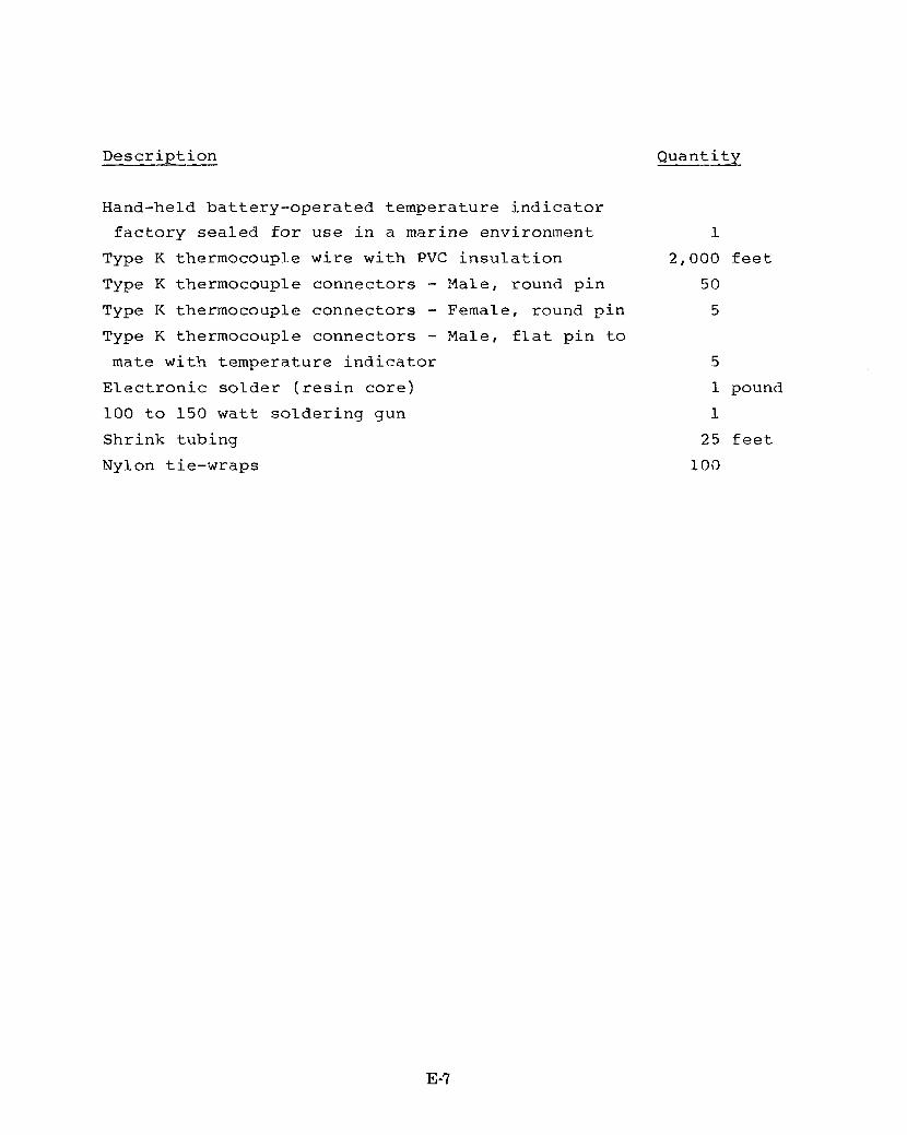
Description - Quantity
Hand-held battery-operated temperature indicator factory sealed for use in a marine environment
Type K thermocouple wire with PVC insulation Type K thermocouple connectors - Male, round pin Type K thermocouple connectors - Female, round pin Type K thermocouple connectors - Male, flat pin to mate with temperature indicator Electronic solder (resin core) 100 to 150 watt soldering gun Shrink tubing Nylon tie-wraps
1
2,000 feet 5 0
5
5
1 pound 1
25 feet 100
E-7
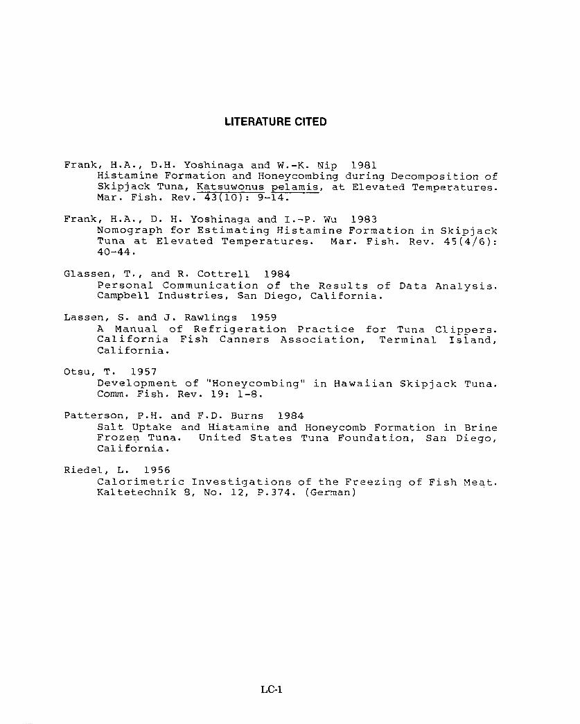
LITERATURE CITED
Frank, H.A., D.H. Yoshinaga and W.-K. Nip 1981 Histamine Formation and Honeycombing during Decomposition of Skipjack Tuna, Katsuwonus peiamis, at Elevated Temperatures. Mar. Fish. Rev. 43(10):-14.
Frank, H.A., D. H. Yoshinaga and I.-P. Wu 1983 Nomograph for Estimating Histamine Formation in Skipjack Tuna at Elevated Temperatures. Mar. Fish. Rev. 45(4/6): 40-44.
Glassen, T., and R. Cottrell 1984 Personal Communication of the Results of Data Analysis. Campbell Industries, San Diego, California.
Lassen, S. and J. Rawlings 1959 A Manual of Refrigeration Practice for Tuna Clippers. California Fish Canners Association, Terminal Island, California.
Otsu, T. 1957 Development of "Honeycombing'' in Hawaiian Skipjack Tuna. Comm. Fish. Rev. 19: 1-8.
Patterson, P . H . and F.D. Burns 1984 Salt Uptake and Histamine and Honeycomb Formation in Brine Frozen Tuna. United States Tuna Foundation, San Diego, California.
Riedel., L. 1956 Calorimetric Investigations of the Freezing of Fish Meat. Kaltetechnik 8, No. 12, P.374. (German)
LC-1