TUFFAK polycarbonate sheet - Professional Plastics...with ANSI Z87.1, EN 169: CSA Z94.3 general IR...
60
TUFFAK ® polycarbonate sheet Fabrication guide / Technical manual
Transcript of TUFFAK polycarbonate sheet - Professional Plastics...with ANSI Z87.1, EN 169: CSA Z94.3 general IR...

TUFFAK® polycarbonate sheetFabrication guide / Technical manual

Table of Contents
2
Page
Introduction . . . . . . . . . . . . . . . . . . . . . . . . . . . . . . . . . . . . . 3
Typical Properties . . . . . . . . . . . . . . . . . . . . . . . . . . . . . . . . 4
TUFFAK Product Selection Guide. . . . . . . . . . . . . . . . 5-6
Chemical / Environmental Resistance . . . . . . . . . . . . 7-13
Cleaning Recommendations . . . . . . . . . . . . . . . . . . . 14-15
Fabrication / Machining. . . . . . . . . . . . . . . . . . . . . . . . 16-21
Fabrication / Laminate & Heavy Gauge Sheet . . 22-25
Thermoforming . . . . . . . . . . . . . . . . . . . . . . . . . . . . . . . 26-31
Troubleshooting Guide . . . . . . . . . . . . . . . . . . . . . . . 32-40
Brake Bending, Cold Forming, Annealing . . . . . . .41-42
Bonding Applications. . . . . . . . . . . . . . . . . . . . . . . . . 43-45
Mechanical Fastening . . . . . . . . . . . . . . . . . . . . . . . . . 46-49
Finishing. . . . . . . . . . . . . . . . . . . . . . . . . . . . . . . . . . . . . 50-52
Glazing Guidelines . . . . . . . . . . . . . . . . . . . . . . . . . . . 53-58

TUFFAK Sheet Typical Properties*
*Typical properties are not intended for specification purposes.4
Property Test Method Units Values PHYSICAL
Specific Gravity ASTM D 792 – 1.2
Refractive Index ASTM D 542 – 1.586
Light Transmission, Clear @ 0.118˝ ASTM D 1003 % 86
Light Transmission, I30 Gray @ 0.118˝ ASTM D 1003 % 50
Light Transmission, K09 Bronze @ 0.118˝ ASTM D 1003 % 50
Light Transmission, I35 Dark Gray @ 0.118˝ ASTM D 1003 % 18
Water Absorption, 24 hours ASTM D 570 % 0.15
Poisson’s Ratio ASTM E 132 – 0.38
MECHANICAL
Tensile Strength, Ultimate ASTM D 638 psi 9,500
Tensile Strength, Yield ASTM D 638 psi 9,000
Tensile Modulus ASTM D 638 psi 340,000
Elongation ASTM D 638 % 110
Flexural Strength ASTM D 790 psi 13,500
Flexural Modulus ASTM D 790 psi 345,000
Compressive Strength ASTM D 695 psi 12,500
Compressive Modulus ASTM D 695 psi 345,000
Izod Impact Strength, Notched @ 0.125˝ ASTM D 256 ft·lbs/in 18
Izod Impact Strength, Unnotched @ 0.125˝ ASTM D 256 ft·lbs/in 60 (no break)
Instrumented Impact @ 0.125˝ ASTM D 3763 ft·lbs 47
Shear Strength, Ultimate ASTM D 732 psi 10,000
Shear Strength, Yield ASTM D 732 psi 6,000
Shear Modulus ASTM D 732 psi 114,000
Rockwell Hardness ASTM D 785 – M70 / R118
THERMAL
Coefficient of Thermal Expansion ASTM D 696 in/in/°F 3.75 x 10⁻⁵
Coefficient of Thermal Conductivity ASTM C 177 BTU·in/hr·ft2·°F 1.35
Heat Deflection Temperature @ 264 psi ASTM D 648 °F 270
Heat Deflection Temperature @ 66 psi ASTM D 648 °F 280
Brittleness Temperature from ductile to brittle ASTM D 746 °F -40 - -200
Shading Coefficient, clear @ 0.236˝ NFRC 100-2010 – 0.97
Shading Coefficient, Gray or Bronze @ 0.236˝ NFRC 100-2010 – 0.77
U factor @ 0.236˝ (summer, winter) NFRC 100-2010 BTU/hr·ft2·°F 0.85, 0.92
U factor @ 0.375˝ (summer, winter) NFRC 100-2010 BTU/hr·ft2·°F 0.78, 0.85
ELECTRICAL
Dielectric Constant @ 10 Hz ASTM D 150 – 2.96
Dielectric Constant @ 60 Hz ASTM D 150 – 3.17
Volume Resistivity ASTM D 257 Ohm·cm 8.2 x 10¹⁶
Dissipation Factor @ 60 Hz ASTM D 150 – 0.0009
Arc Resistance
Stainless Steel Strip electrode ASTM D 495 Seconds 10
Tungsten Electrodes ASTM D 495 Seconds 120
Dielectric Strength, in air @ 0.125˝ ASTM D 149 V/mil 380
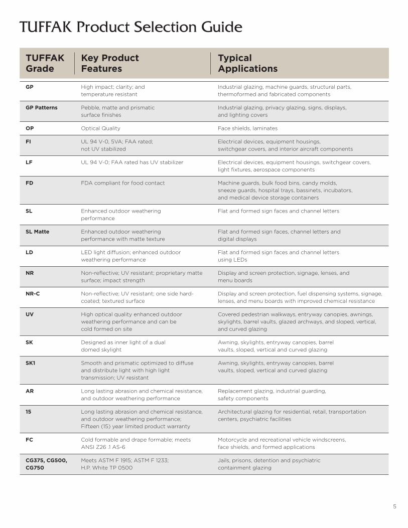
TUFFAK Product Selection Guide
5
TUFFAK Key Product Typical Grade Features Applications
GP High impact; clarity; and Industrial glazing, machine guards, structural parts, temperature resistant thermoformed and fabricated components
GP Patterns Pebble, matte and prismatic Industrial glazing, privacy glazing, signs, displays, surface finishes and lighting covers
OP Optical Quality Face shields, laminates
FI UL 94 V-0, 5VA; FAA rated; Electrical devices, equipment housings, not UV stabilized switchgear covers, and interior aircraft components
LF UL 94 V-0; FAA rated has UV stabilizer Electrical devices, equipment housings, switchgear covers, light fixtures, aerospace components
FD FDA compliant for food contact Machine guards, bulk food bins, candy molds, sneeze guards, hospital trays, bassinets, incubators, and medical device storage containers
SL Enhanced outdoor weathering Flat and formed sign faces and channel letters performance
SL Matte Enhanced outdoor weathering Flat and formed sign faces, channel letters and performance with matte texture digital displays
LD LED light diffusion; enhanced outdoor Flat and formed sign faces and channel letters weathering performance using LEDs
NR Non-reflective; UV resistant; proprietary matte Display and screen protection, signage, lenses, and surface; impact strength menu boards
NR-C Non-reflective; UV resistant; one side hard- Display and screen protection, fuel dispensing systems, signage, coated; textured surface lenses, and menu boards with improved chemical resistance
UV High optical quality enhanced outdoor Covered pedestrian walkways, entryway canopies, awnings, weathering performance and can be skylights, barrel vaults, glazed archways, and sloped, vertical, cold formed on site and curved glazing
SK Designed as inner light of a dual Awning, skylights, entryway canopies, barrel domed skylight vaults, sloped, vertical and curved glazing
SK1 Smooth and prismatic optimized to diffuse Awning, skylights, entryway canopies, barrel and distribute light with high light vaults, sloped, vertical and curved glazing transmission; UV resistant
AR Long lasting abrasion and chemical resistance, Replacement glazing, industrial guarding, and outdoor weathering performance safety components
15 Long lasting abrasion and chemical resistance, Architectural glazing for residential, retail, transportation and outdoor weathering performance; centers, psychiatric facilities Fifteen (15) year limited product warranty
FC Cold formable and drape formable; meets Motorcycle and recreational vehicle windscreens, ANSI Z26 .1 AS-6 face shields, and formed applications
CG375, CG500, Meets ASTM F 1915; ASTM F 1233; Jails, prisons, detention and psychiatric CG750 H.P. White TP 0500 containment glazing
6
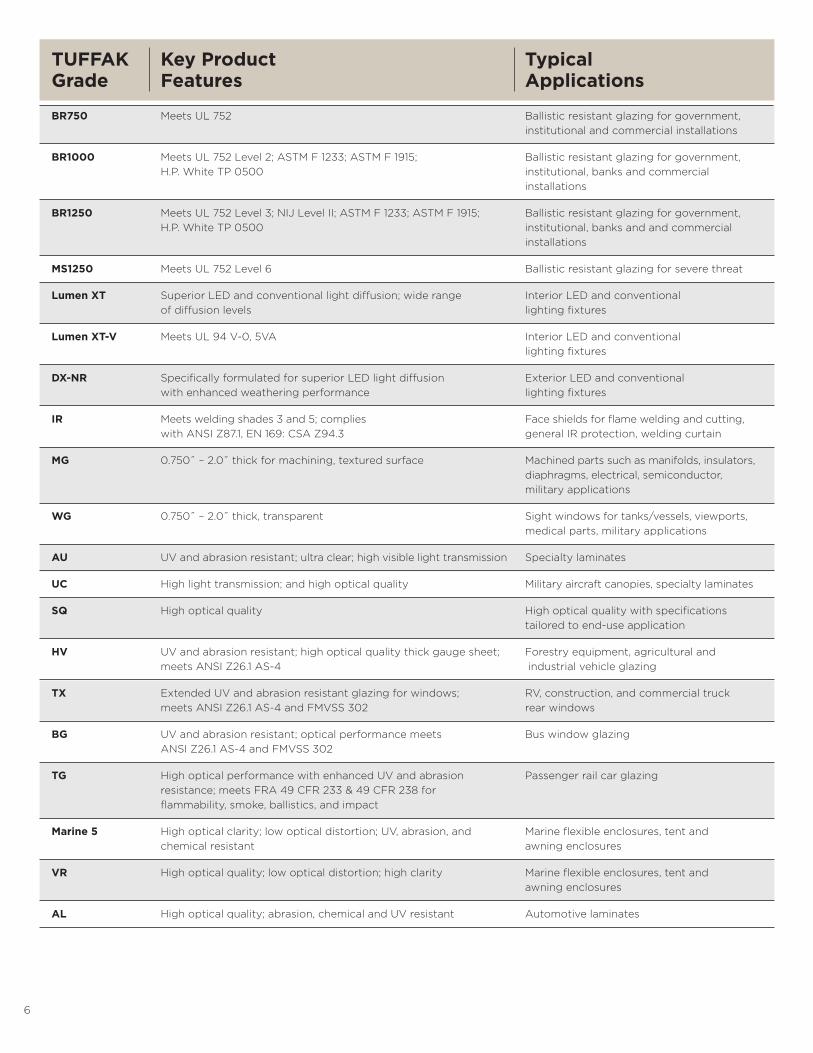
TUFFAK Key Product Typical Grade Features Applications
BR750 Meets UL 752 Ballistic resistant glazing for government, institutional and commercial installations
BR1000 Meets UL 752 Level 2; ASTM F 1233; ASTM F 1915; Ballistic resistant glazing for government, H.P. White TP 0500 institutional, banks and commercial installations
BR1250 Meets UL 752 Level 3; NIJ Level II; ASTM F 1233; ASTM F 1915; Ballistic resistant glazing for government, H.P. White TP 0500 institutional, banks and and commercial installations
MS1250 Meets UL 752 Level 6 Ballistic resistant glazing for severe threat
Lumen XT Superior LED and conventional light diffusion; wide range Interior LED and conventional of diffusion levels lighting fixtures
Lumen XT-V Meets UL 94 V-0, 5VA Interior LED and conventional lighting fixtures
DX-NR Specifically formulated for superior LED light diffusion Exterior LED and conventional with enhanced weathering performance lighting fixtures
IR Meets welding shades 3 and 5; complies Face shields for flame welding and cutting, with ANSI Z87.1, EN 169: CSA Z94.3 general IR protection, welding curtain
MG 0.750˝ – 2.0˝ thick for machining, textured surface Machined parts such as manifolds, insulators, diaphragms, electrical, semiconductor, military applications
WG 0.750˝ – 2.0˝ thick, transparent Sight windows for tanks/vessels, viewports, medical parts, military applications
AU UV and abrasion resistant; ultra clear; high visible light transmission Specialty laminates
UC High light transmission; and high optical quality Military aircraft canopies, specialty laminates
SQ High optical quality High optical quality with specifications tailored to end-use application
HV UV and abrasion resistant; high optical quality thick gauge sheet; Forestry equipment, agricultural and meets ANSI Z26.1 AS-4 industrial vehicle glazing
TX Extended UV and abrasion resistant glazing for windows; RV, construction, and commercial truck meets ANSI Z26.1 AS-4 and FMVSS 302 rear windows
BG UV and abrasion resistant; optical performance meets Bus window glazing ANSI Z26.1 AS-4 and FMVSS 302
TG High optical performance with enhanced UV and abrasion Passenger rail car glazing resistance; meets FRA 49 CFR 233 & 49 CFR 238 for flammability, smoke, ballistics, and impact
Marine 5 High optical clarity; low optical distortion; UV, abrasion, and Marine flexible enclosures, tent and chemical resistant awning enclosures
VR High optical quality; low optical distortion; high clarity Marine flexible enclosures, tent and awning enclosures
AL High optical quality; abrasion, chemical and UV resistant Automotive laminates
7
Chemical / Environmental
Resistance
8
Chemical / Environmental ResistanceThe chemical and environmental resistance of TUFFAK depends on the unique combination of factors and variables it encounters in its application.
Outlined below is an overview of its primary outside influencers, and common types of potential damage. A summary of laboratory tests designed to meet its practical requirements, as well as its resistance to a wide range of chemicals and substances, is also provided.
Your Plaskolite Representative, with the support of our Technical Service Group, is available to work with you to evaluate your specific application.
Influencing parametersTUFFAK properties are influenced chiefly by: » The composition of chemical ingredients
» Temperature
» Duration of exposure
» The level of internal or applied stress and strain
Types of damageTUFFAK can sustain several distinct types of damage, including swelling, dissolution, stress cracking and molecular degradation. Circumstances under which these potential types of damage can occur are detailed below. Different chemicals may act simultaneously on TUFFAK sheet causing one or more types of damage.
Swelling or dissolution
When low-molecular, aromatic, halogenated and polar components migrate into the polycarbonate, the damage can range from a tacky surface, to swelling, to complete dissolution.
Stress crackingEven in small quantities, a number of chemicals can penetrate the surface of TUFFAK. This may result in stress cracks that affect the formed or fabricated part’s appearance or mechanical properties.
With transparent grades of TUFFAK, stress cracks are generally easy to detect. In opaque grades, it may be difficult to detect them. Stress cracks can act like a notch, leading to significant deterioration in several mechanical properties, particularly impact, flexural and tensile performance. Laboratory tests such as impact or flexural strength can be used as indicators for mechanical property degradation.
Temperature and the duration of exposure are key influencers in the potential cracking of TUFFAK. As temperature rises, the time that elapses before damage occurs shortens. The exposure time required for initial damage ranges from a few seconds to more than 1000 hours due to the chemical involved, temperature, and stress level. For example, when formed or fabricated parts with pronounced stresses are immersed in aggressive solvents, stress cracks will occur in less than one minute.
It is possible for a component within a solid to migrate to polycarbonate through long-term contact and cause damage. One example is the contact between polycarbonate and plasticized PVC. Plasticizers within PVC, such as phthalates can trigger stress cracking and result in damage to the polycarbonate.
Molecular degradationMany of TUFFAK properties are determined by the size of its molecules. If an incompatible chemical causes a reduction in molecular weight, mechanical property degradation can occur. The molecular weight has virtually no influence on electrical properties and only a slight influence on thermal properties.
Solutions with a high pH (bases) can act to lower the molecular weight of polycarbonate. Low pH (acids) solutions typically do not degrade the molecular weight. Ammonia and amines are aggressive towards polycarbonate.
Plaskolite laboratories have tested a series of chemicals and commercial products to determine their compatibility with polycarbonate. The results of TUFFAK resistance to substances are included in the following table (pages 10-13).
Laboratory tests supply information on the formulation tested. The composition of many commercial products can change over time.
Oxidative damageTUFFAK is relatively stable toward oxidizing agents such as oxygen, nitric acid, and hydrogen peroxide.
ResistanceTUFFAK’s resistance to chemicals, common industrial cleaners, pharmaceuticals, household and cosmetic substances, is dependent on the ingredients in the product, as well as the temperature and duration of exposure. The following section provides a general overview of resistance to these commonly used materials. If you require additional information, please contact your Plaskolite representative.
» Resistance to sealing compounds, adhesives and plastics TUFFAK’s resistance to sealants, adhesives and plastics is largely dependent on the presence of aggressive components, such as plasticizers (e.g., phthalates) or solvents, which can migrate into polycarbonate.
» Resistance to paints Solvents in paints may cause stress cracking or swelling depending upon the solvent and the flash-off and drying conditions. It is possible to formulate paints with solvents that do not cause damage. In some applications, painting can increase the chemical resistance of the finished part.
Two component paints are resistant if the individual components do not cause damage to TUFFAK in the short period between the application and curing. The SDS can be used to identify the chemical composition of the paint.
» Resistance to cleaning and washing agents TUFFAK is resistant to most household soaps but not those containing amines, ammonia and sodium hydroxide.
» Resistance to disinfectants, drugs and cosmetics TUFFAK may be damaged by disinfectants, drugs and cosmetics, which contain solvents or active ingredients that are incom-patible with polycarbonate. For example, nail polish and nail polish remover will cause damage to the material.
If the product ingredients are known, it is possible to estimate the compatibility with TUFFAK. However, it is recommended to put the finished part through a practical test if no data is available. Refer to the compatibility table (pages 10-13) for resistance levels.

9
Chemical / Environmental ResistanceTesting to meet practical requirements
The compatibility information presented in this section should be used as a starting point for determining the integrity and durability of your application. Testing is essential if finished TUFFAK components are likely to encounter aggressive chemicals during use. The internal and applied stress in a formed or fabricated part, as well as duration of chemical exposure, can lead to very different results.
Compatibility assessment methods
The data shown in the compatibility table (pages 10-13) was generated using DIN 53449-3. This method uses test pieces of 80 x 10 x 4 mm TUFFAK sheet clamped to a curved fixture. The fixture applies a graduated strain ranging from 0 to 2%.
Assessment criteriaThe information in the compatibility table is based on exposure to chemicals at 23°C and a range from 0-2% strain. Components that lead to damage with a strain of e < 1.0 % are classified as incompatible.
The results shown in the following tables are based on a one-time test. Change in the composition by the producers of these substances can change the results.
Please contact your Plaskolite representative or the Technical Service Group at 800.628.5084 with any questions, or if you require additional information.

10
Chemical / Environmental Resistance
Chlorine lime, 2% in water +Chloroform -Chrom alum, saturated aqueous solution +Chromic acid, 20% in water +Citric acid +Copper sulphate, saturated aqueous solution +Cresol -Cupric chloride, saturated aqueous solution +Cuprous chloride, saturated aqueous solution +Cyclo hexane -Cyclo hexanol OCyclo hexanone -Dekaline +Diamyl phthalate -Dibutyl phthalate (plasticizer) -Diethylene glykol +Diethylether -Diglycolic acid, saturated aqueous solution +Dimethyl formamide -Dinonyl phthalate (plasticizer) ODioctyl phthalate (plasticizer) ODioxane -Diphyl 5, 3 O Ether -Ethyl alcohol, 96% pure +Ethyl amine -Ethyl bromide -Ethylene chlorohydrine -Ethylene chloride -Ethylene glykol +Ferritrichloride, saturated aqueous solution +Ferro bisulphate +Formaline, 10%ig +Formic acid, 30% OGasoline +Glycerine OGlycol +Heptane +Hexane +Hydrochloric acid, 20% +Hydrochloric acid, conc. -Hydrofluoric acid, 5% +Hydrofluoric acid, conc. -Hydrofluorosilicic acid, 30% +Hydrogen peroxide, 30% +Iodine -Isoamyl alcohol OIsopropyl alcohol +Lactic acid, 10% in water +Lead tetraethylene, 10% in gasoline OLighting gas +
LegendExplanation of the symbols:
+ Resistant O Partially resistant - Not Resistant
Chemicals
Acetaldehyde -Acetic acid, up to 10% solution +Acetone -Acetylene +Acrylonitrile -Allylalcohol OAlum +Aluminum chloride, saturated aqueous solution +Aluminum oxalate +Aluminum sulphate, saturated aqueous solution +Ammonia -Ammoniacal liquor -Ammonium chloride, saturated aqueous solution +Ammonium nitrate, saturated aqueous solution +Ammonium sulphate,saturated aqueous solution +Ammonium sulphide, saturated aqueous solution -Amylo acetate -Aniline -Antimony chloride, saturated aqueous solution +Arsenic acid, 20% solution +Benzaldehyde -Benzene - Benzoic acid -Benzyl alcohol -Borax, saturated aqueous solution +Boric acid + Bromic benzene -Bromine -Butane (liquid or gaseous) +Butyl acetate -Butanol +Butylene glycol +Butyric acid -Calcium chloride, saturated aqueous solution +Calcium hypochloride + Calcium nitrate, saturated aqueous solution +Calcium-soap, fat/pure +Carbon acid, wet +Carbon monoxide +Chlorine benzene -Chlorine gas, dry OChlorine gas, wet -Chlorine lime slurry +

11
Chemical / Environmental Resistance
Ligroin (hydrocarbon compound) +Lime milk, 30% in water OMagnesium chloride, saturated aqueous solution +Magnesium sulphate, saturated aqueous solution +Manganous sulphate, saturated aqueous solution +Mercuro chloride, saturated aqueous solution +Mercury +Methacrylic acid-methyester (MMA) -Methane +Methanol -Methyl amine -Methyl ethyl ketone (MEK) -Methylene chloride -Nitric acid, 10% +Nitric acid, 10-20% ONitric acid, 20% -Nitric Gas, dry -Nitrobenzene -Oxalic acid, 10% in water +Oxygen +Ozone +Pentane +Perchloric acid, 10% in water +Perchloric acid, concentrated OPerchloro ethylene -Perhydrol, 30% +Petroleum OPetroleum ether OPetroleum spirit +Phenol -Phenyl ethyl alcohol -Phosphor trichloride -Phosphoric acid, conc. +Phosphoric oxichloride -Potassium aluminum sulpate, saturated aqueous solution +Potassium bichromate, saturated aqueous solution +Potassium bromide, saturated aqueous solution +Potassium carbonate, saturated aqueous solution +Potassium chloride, saturated aqueous solution +Potassium cyanide -Potassium hydroxide -Potassium metabisulphide, 4% in water +Potassium nitrate, saturated aqueous solution +Potassium perchlorate, 10% in water +Potassium permanganate, 10% in water +Potassium persulphate, 10% in water +Potassium rhodanide, saturated aqueous solution +Potassium sulphate, saturated aqueous solution +Propane gas +Propargyl alcohol +Propionic acid, 20% +
Propionic acid, conc. -Propyl alcohol +Pyridine -Resorcin oil solution, 1% +Carbon disulphide -Hydrogen sulphide +Soda +Sodium bicarbonate, saturated aqueous solution +Sodium bisulphate, saturated aqueous solution +Sodium bisulphide, saturated aqueous solution +Sodium carbonate, saturated aqueous solution +Sodium chlorate, saturated aqueous solution +Sodium chloride, saturated aqueous solution +Sodium hydroxide -Sodium hypochloride, 5% in water +Sodium sulphate, saturated aqueous solution +Sodium sulphide, saturated aqueous solution OStyrene -Sublimate, saturated aqueous solution +Sulphur +Sulphur dioxide OSulphuric acid, 50% +Sulphuric acid, 70% OSulphuric acid, conc. -Sulphurous acid, 10% -Sulphuryl chloride -Tartaric acid, 10% +Tetrachlorocarbon -Tetrachloroethane -Tetrahydrofurane -Tetraline -Thiophene -Toluene -Trichloro acetic acid, 10% OTrichloroethyl amine -Trichloroethyl phosphate (plasticizer) OTrichloroethylene -Tricresyl phosphate (plasticizer) -Urea, saturated aqueous solution +Water +Xylene -Zinc chloride, saturated aqueous solution +Zinc oxide +Zinc sulphate, saturated aqueous solution +

12
Nutrition
Allspice -Apple juice +Beef sebum +Beer +Beets syrup +Brandy, 38% +Butter +Chocolate +Cinnamon +Clove -Cod-liver oil +Coffee +Common salt +Fish +Fruit juice +Fruit syrup (Raspberry) +Gherkins +Grape sugar +Grapefruit juice +Juniper berry +Lard OLinseed oil +Liquor + Margarine +Meat +Milk +Mineral water +Mustard +Nutmeg -Onion +Orange juice +Paprika +Pepper +Rum +Salad oil +Syrup +Sugar solution, saturated aqueous solution +Tea +Tobacco +Tomato juice +Tomato puree +Vanilla +Vegetable juice +Vegetable oils +Vinegar +Vodka +Water +Wine +Worcestershire sauce +
Chemical / Environmental ResistanceDisinfectants
Accel TB -Baktol®, 5% +Carbolic acid -Chloroamine +Clorox® BROAD SPECTRUM Quaternary Disinfectant Cleaner -Clorox® Healthcare FUZION Cleaner Disinfectant -Clorox® Healthcare Bleach Germicidal Cleaner -Delegol®, 5% +Dimamin T, 5% OHydrogen peroxide +Iodine tincture OLysoform, 2% +Lysol® Brand III Disinfectant Spray (original) -Maktol® +Merfen®, 2% +Oktozon®, 1% +PDI® Super Sani-Cloth® Disposable Wipes -Perhydrol +PeridoxRTU® Sporicidal Disinfectant -Resorcinol solutions, 1% +Safetec Surface Safe Wipes -Sagrotan®, 5% OSpirit, pure +Steriplex® SD -Sublimate +TB-Lysoform -Trosilin G extra®, 1, 5% +ZEP® 40 Non-Streaking Cleaner -ZEP® SPIRIT II -Zephirol® O
Pharmaceutics and cosmetics
Blood plasma +Delial-Sunmilk® +Botanicare® Hydroplex +Iodine tincture OKlosterbalsam +Lanoline +Menthol, 90% in Alcohol ONail polish -Nail polish remover -Odol-mouthwash® +Periston blood substitute® +Vaseline +Vicks® VapoRub® +

13
Chemical / Environmental ResistanceWashing and cleaning agents
Household soap +Top Job +Joy® +Palmolive Liquid® +
Technical oils and fats
Camphor oil -Castor oil +Cod-liver oil +Drilling oil -Fish oil +Fuel oil OLubricant based on paraffin +Paraffin oil +
Sodium soap fat +
Miscellaneous
Battery acid +Blood +Castor oil +Cement +Freon® 113 +Gasoline ONatural rubber +Oleic acid, conc. +Polishing wax +Polyethylene +Polyvinylchloride, (containing plasticizer) OSea water +Starch +Weak acid >4.7 pH +Weak base <9.5 pH OTannic acid -

14
Cleaning Recommendations
15
Cleaning RecommendationsTUFFAK cleaning instructions
Periodic cleaning of TUFFAK is recommended to prolong the service life of your material. To minimize the risk of damage, use only compatible household cleaners and correct cleaning procedures as outlined below.
TUFFAK GP polycarbonate mars easily with wiping action. TUFFAK 15, TUFFAK AR, and Hygard laminate sheets are hard coated, abrasion and mar resistant polycarbonate products that offer a high degree of surface hardness and abrasion resistance. These products provide superior protection against unintentional chemical attack. However, the use of abrasive, gritty cleaners or hard cleaning implements (e.g., hard brushes, scrapers, squeegees) should be avoided to eliminate the possibility of scratching the coating.
Compatible cleanersThe following cleaning agents are compatible with TUFFAK polycarbonate sheet products when used according to the manufacturer’s recommendations:
» Top Job
» Joy®
» Palmolive Liquid®
» Windex® Ammonia freeTop Job and Joy are registered trademarks of Proctor & Gamble, Palmolive is a registered trademark of Colgate Palmolive, Windex is a registered trademark of Drackett Products.
General cleaning instructions:» Thoroughly pre-rinse with warm water to loosen and wash away surface residue, grit and grime.
» Using a soft microfiber cloth or moist non-abrasive sponge, gently wash with a mild diluted soap or detergent.
» Rinse thoroughly with lukewarm, clean water. To prevent water spots, thoroughly dry the glazing with a dry soft cloth.
Removing heavy oils and tars:» Thoroughly pre-rinse with warm water to loosen and wash away surface residue, grit and grime.
» With a 50/50 isopropyl alcohol-water mixture, gently rub the area with a soft non-abrasive cloth.
» Immediately rinse thoroughly with lukewarm clean water. To prevent water spots, thoroughly dry the glazing with a dry soft cloth.
Removing graffiti, paint, marker, inks and glazing compounds:» Thoroughly pre-rinse with warm water to loosen and wash away surface residue, grit and grime.
» Using Naphtha VM&P grade, Isopropyl Alcohol or Butyl Cellosolve™, gently rub the area with a soft, non-abrasive cloth. Do not apply solvent cleaners under direct sunlight or during high temperatures.
» Immediately rinse thoroughly with lukewarm clean water. To prevent water spots, thoroughly dry the glazing with a dry soft cloth.
Removing adhesive-backed labels:» Isopropyl Alcohol, Naphtha VM&P grade or Kerosene will help lift stickers and adhesives.
» Immediately rinse thoroughly with lukewarm clean water. To prevent water spots, thoroughly dry the glazing with a dry soft cloth.
Important reminders» Do not clean TUFFAK with any cleaners other than those on the approved, compatible list included in this guide, or those tested and found compatible.
» Do not use abrasive cleaners.
» Do not use high alkaline cleaners (high pH or ammoniated).
» Do not leave cleaners sitting on TUFFAK for periods of time; rinse off immediately.
» Do not apply cleaners under direct sunlight or at elevated temperatures.
» Do not use scrapers, squeegees, razors or other sharp instruments as they may permanently scratch TUFFAK.
» Do not dry rub or dry clean TUFFAK, as sand and dust particles clinging to the exterior of the glazing may scratch its surface. An Anti-Static Canned-Air Ionizer can reduce electro static charge buildup on TUFFAK, and aids in reducing dirt and dust buildup that can hinder cleaning.
Contact the Plaskolite Technical Service Group at 800.628.5084 with any questions.
TECH TIP:The edges of coated polycarbonate sheet are not protected with an abrasion and chemical resistant hard coating. Do not allow cleaning solutions and solvents to pool along the edges for any length of time. Always rinse edges thoroughly with generous amounts of lukewarm clean water.
Removing scratchesDeep scratches and gouges made by sharp objects such as keys, screwdrivers, and knives cannot be repaired. Fine scratches may be reduced in severity or cosmetically hidden by using a buffing compound such as NOVUS® 2 Plastic Fine Scratch Remover, followed by a cleaning and polishing agent like NOVUS® 1. However, for abrasion resistant coated products, buffing the surface is not recommended. Buffing these scratched sites worsen the condition and further damage the coating. Once the coating is removed, it cannot be repaired and buffing may optically distort the window.
Butyl Cellosolve™ is a trademark of DOW.
Novus® 1 and Novus® 2 are registered trademarks of Novus® Plastic Polish.
16
Fabrication
17
Fabrication – Introduction
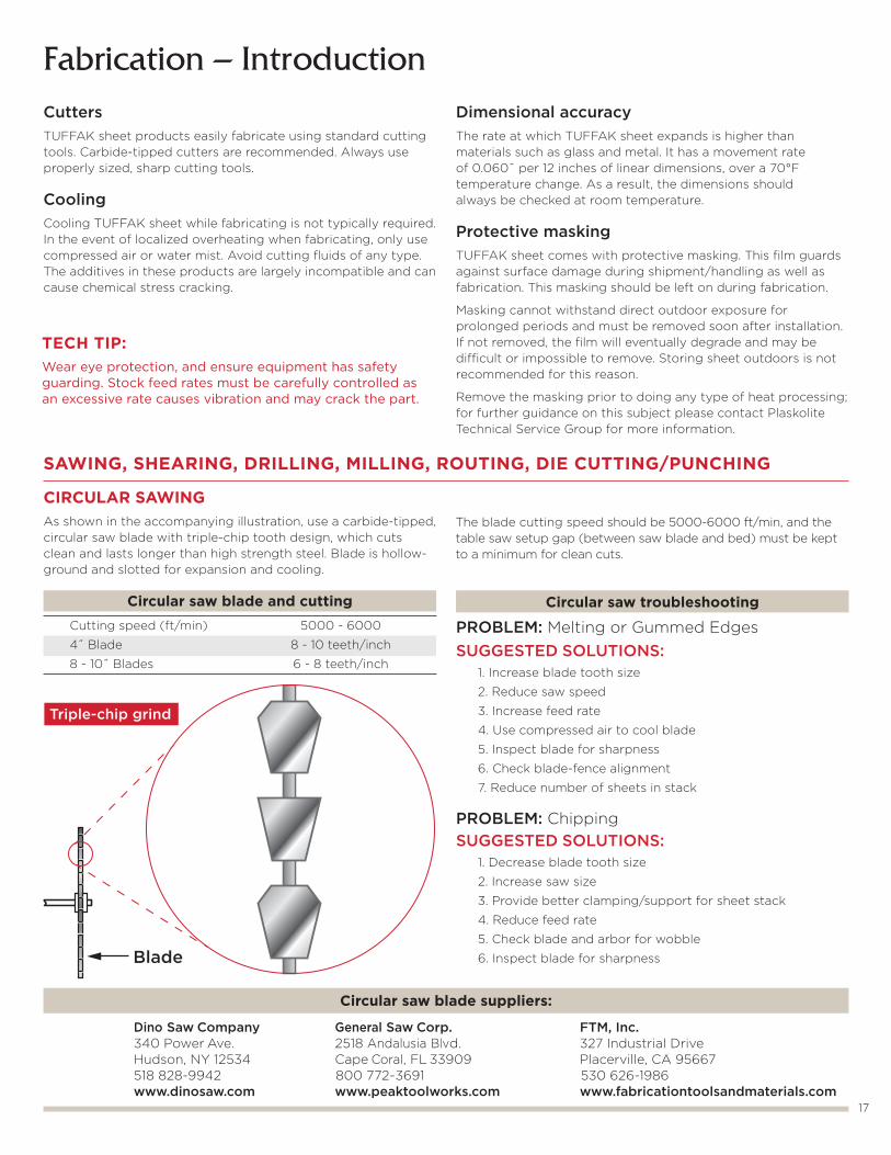
Circular saw troubleshooting
PROBLEM: Melting or Gummed EdgesSUGGESTED SOLUTIONS: 1. Increase blade tooth size
2. Reduce saw speed
3. Increase feed rate
4. Use compressed air to cool blade
5. Inspect blade for sharpness
6. Check blade-fence alignment
7. Reduce number of sheets in stack
PROBLEM: ChippingSUGGESTED SOLUTIONS: 1. Decrease blade tooth size
2. Increase saw size
3. Provide better clamping/support for sheet stack
4. Reduce feed rate
5. Check blade and arbor for wobble
6. Inspect blade for sharpness
CIRCULAR SAWINGAs shown in the accompanying illustration, use a carbide-tipped, circular saw blade with triple-chip tooth design, which cuts clean and lasts longer than high strength steel. Blade is hollow-ground and slotted for expansion and cooling.
Circular saw blade and cutting Cutting speed (ft/min) 5000 - 6000
4˝ Blade 8 - 10 teeth/inch
8 - 10˝ Blades 6 - 8 teeth/inch
Blade
Circular saw blade suppliers:
Dino Saw Company General Saw Corp. FTM, Inc. 340 Power Ave. 2518 Andalusia Blvd. 327 Industrial Drive Hudson, NY 12534 Cape Coral, FL 33909 Placerville, CA 95667 518 828-9942 800 772-3691 530 626-1986 www.dinosaw.com www.peaktoolworks.com www.fabricationtoolsandmaterials.com
Triple-chip grind
CuttersTUFFAK sheet products easily fabricate using standard cutting tools. Carbide-tipped cutters are recommended. Always use properly sized, sharp cutting tools.
CoolingCooling TUFFAK sheet while fabricating is not typically required. In the event of localized overheating when fabricating, only use compressed air or water mist. Avoid cutting fluids of any type. The additives in these products are largely incompatible and can cause chemical stress cracking.
Dimensional accuracyThe rate at which TUFFAK sheet expands is higher than materials such as glass and metal. It has a movement rate of 0.060˝ per 12 inches of linear dimensions, over a 70°F temperature change. As a result, the dimensions should always be checked at room temperature.
Protective maskingTUFFAK sheet comes with protective masking. This film guards against surface damage during shipment/handling as well as fabrication. This masking should be left on during fabrication.
Masking cannot withstand direct outdoor exposure for prolonged periods and must be removed soon after installation. If not removed, the film will eventually degrade and may be difficult or impossible to remove. Storing sheet outdoors is not recommended for this reason.
Remove the masking prior to doing any type of heat processing; for further guidance on this subject please contact Plaskolite Technical Service Group for more information.
The blade cutting speed should be 5000-6000 ft/min, and the table saw setup gap (between saw blade and bed) must be kept to a minimum for clean cuts.
SAWING, SHEARING, DRILLING, MILLING, ROUTING, DIE CUTTING/PUNCHING
TECH TIP:Wear eye protection, and ensure equipment has safety guarding. Stock feed rates must be carefully controlled as an excessive rate causes vibration and may crack the part.
1˝8 - 12 teethper inch
18
BAND SAWINGBand sawing is preferred for cutting contour and irregular shapes.
General guidelines:» Use precision or standard blades for sheet and parts made from thin gauge
» Use buttress or skip-tooth blades for sheets thicker than 1/8 inch
» Choose band-saw blades with generous set to reduce friction and heat buildup
» Cool the cut junction with air or a water mist
» Control the feed rate carefully to prevent binding and gumming
» Use saw guides whenever possible
Band saw troubleshooting
PROBLEM: Melting or Gummed EdgesSUGGESTED SOLUTIONS: 1. Increase blade tooth size
2. Reduce saw speed
3. Use compressed air to cool blade
4. Check blade sharpness
PROBLEM: ChippingSUGGESTED SOLUTIONS: 1. Decrease blade tooth size
2. Slow down stock feed rate
3. Provide better clamping/support to eliminate vibration
4. Check blade sharpness
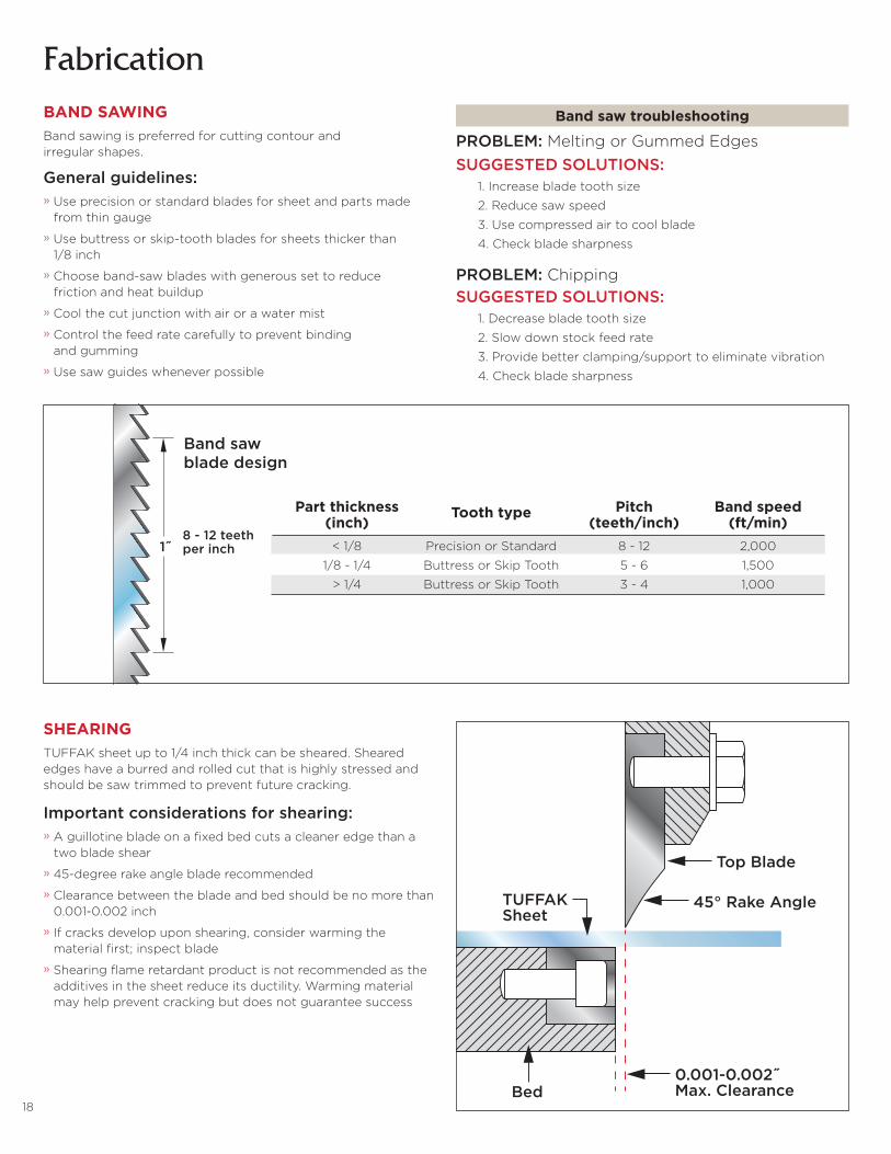
Part thickness Tooth type Pitch Band speed (inch) (teeth/inch) (ft/min) < 1/8 Precision or Standard 8 - 12 2,000
1/8 - 1/4 Buttress or Skip Tooth 5 - 6 1,500
> 1/4 Buttress or Skip Tooth 3 - 4 1,000
SHEARING TUFFAK sheet up to 1/4 inch thick can be sheared. Sheared edges have a burred and rolled cut that is highly stressed and should be saw trimmed to prevent future cracking.
Important considerations for shearing:» A guillotine blade on a fixed bed cuts a cleaner edge than a two blade shear
» 45-degree rake angle blade recommended
» Clearance between the blade and bed should be no more than 0.001-0.002 inch
» If cracks develop upon shearing, consider warming the material first; inspect blade
» Shearing flame retardant product is not recommended as the additives in the sheet reduce its ductility. Warming material may help prevent cracking but does not guarantee success
Fabrication
Band saw blade design
Top Blade
45° Rake AngleTUFFAKSheet
Bed0.001-0.002˝Max. Clearance
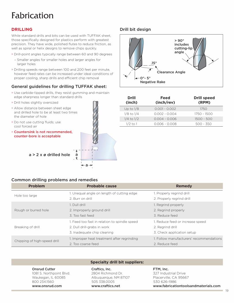
a > 2 x ø drilled hole
a
a
19
FabricationDRILLINGWhile standard drills and bits can be used with TUFFAK sheet, those specifically designed for plastics perform with greatest precision. They have wide, polished flutes to reduce friction, as well as spiral or helix designs to remove chips quickly.
» Drill-point angles typically range between 60 and 90 degrees
– Smaller angles for smaller holes and larger angles for larger holes
» Drilling speeds range between 100 and 200 feet per minute, however feed rates can be increased under ideal conditions of proper cooling, sharp drills and efficient chip removal
General guidelines for drilling TUFFAK sheet:» Use carbide-tipped drills, they resist gumming and maintain edge sharpness longer than standard drills
» Drill holes slightly oversized
» Allow distance between sheet edge and drilled hole to be at least two times the diameter of hole
» Do not use cutting fluids; use cool forced air
» Countersink is not recommended, counter-bore is acceptable
Drill Feed Drill speed (inch) (inch/rev) (RPM) Up to 1/8 0.001 - 0.002 1750
1/8 to 1/4 0.002 - 0.004 1750 - 1500
1/4 to 1/2 0.004 - 0.006 1500 - 500
1/2 to 1 0.006 - 0.008 500 - 350
Drill bit design
0°- 5°Negative Rake
Clearance Angle
.15°
> 90°includescutting-lipangle
Problem Probable cause Remedy
Hole too large
1. Unequal angle on length of cutting edge 1. Properly regrind drill
2. Burr on drill 2. Properly regrind drill
1. Dull drill 1. Regrind properly
Rough or burred hole 2. Improperly ground drill 2. Regrind properly
3. Too fast feed 3. Reduce feed
1. Feed too fast in relation to spindle speed 1. Reduce feed or increase speed
Breaking of drill 2. Dull drill-grabs in work 2. Regrind drill
3. Inadequate chip cleaning 3. Check application setup
Chipping of high-speed drill
1. Improper heat treatment after regrinding 1. Follow manufacturers’ recommendations
2. Too coarse feed 2. Reduce feed
Common drilling problems and remedies
Specialty drill bit suppliers:
Onsrud Cutter Craftics, Inc. FTM, Inc. 1081 S. Northpoint Blvd. 2804 Richmond Dr. 327 Industrial Drive Waukegan, IL 60085 Albuquerque, NM 87107 Placerville, CA 95667 800 234.1560 505 338.0005 530 626-1986 www.onsrud.com www.craftics.net www.fabricationtoolsandmaterials.com
20
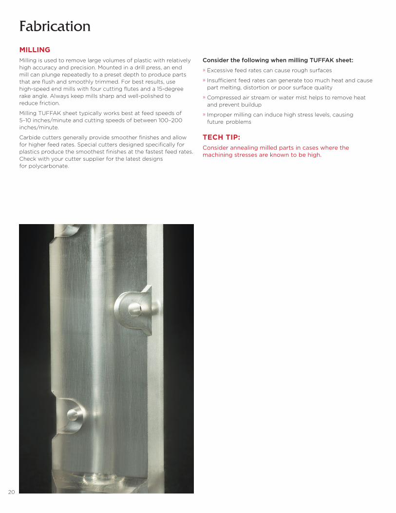
FabricationMILLINGMilling is used to remove large volumes of plastic with relatively high accuracy and precision. Mounted in a drill press, an end mill can plunge repeatedly to a preset depth to produce parts that are flush and smoothly trimmed. For best results, use high-speed end mills with four cutting flutes and a 15-degree rake angle. Always keep mills sharp and well-polished to reduce friction.
Milling TUFFAK sheet typically works best at feed speeds of 5–10 inches/minute and cutting speeds of between 100–200 inches/minute.
Carbide cutters generally provide smoother finishes and allow for higher feed rates. Special cutters designed specifically for plastics produce the smoothest finishes at the fastest feed rates. Check with your cutter supplier for the latest designs for polycarbonate.
Consider the following when milling TUFFAK sheet:
» Excessive feed rates can cause rough surfaces
» Insufficient feed rates can generate too much heat and cause part melting, distortion or poor surface quality
» Compressed air stream or water mist helps to remove heat and prevent buildup
» Improper milling can induce high stress levels, causing future problems
TECH TIP:Consider annealing milled parts in cases where the machining stresses are known to be high.
21
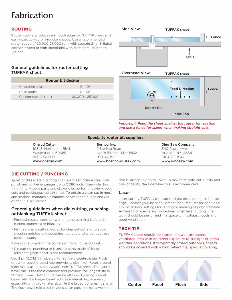
Router bit design Clearance angle 5 - 10°
Rake angle 0 - 10°
Cutting speed (rpm) 20,000 - 25,000
ROUTINGRouter cutting produces a smooth edge on TUFFAK sheet and easily cuts curved or irregular shapes. Use a recommended router speed of 20,000-25,000 rpm, with straight 2- or 3-fluted carbide-tipped or high-speed bits with diameters 1/4 inch to 1/2 inch.
General guidelines for router cutting TUFFAK sheet:
Important: Feed the sheet against the router bit rotation and use a fence for sizing when making straight cuts.
Specialty router bit suppliers:
Onsrud Cutter Boshco, Inc. Dino Saw Company 1081 S. Northpoint Blvd. 2 Sterling Road 340 Power Ave. Waukegan, IL 60085 North Billerica, MA 01862 Hudson, NY 12534 800 234.1560 978 667.1911 518 828-9942 www.onsrud.com www.boshco-dustek.com www.dinosaw.com
TUFFAK sheetSide View
Overhead View
Fence
Table
Table Top
FenceFeed Direction
Router Bit
TUFFAK sheet
Fabrication
DIE CUTTING / PUNCHING Types of dies used in cutting TUFFAK sheet include steel-rule, punch and clicker in gauges up to 0.080 inch. Steel-rule dies trim lighter-gauge parts and clicker dies perform heavier-gauge cuts and continuous cuts in sheet. To obtain a clean cut in most applications, maintain a clearance between the punch and die of about 0.005 inches.
General guidelines when die cutting, punching or blanking TUFFAK sheet:» For best results, consider warming the part first before die cutting, punching or blanking
» Maintain sharp cutting edges for cleanest cut and to avoid creating notches and scratches that could later act as stress concentrators
» Avoid sharp radii in the corners of non-circular cut-outs
» Die cutting, punching or blanking parts made of flame retardant grade sheet is not recommended
Use 3 pt (0.042˝) thick steel to fabricate steel-rule die. Flush or center bevel-ground rule provides a clean cut. Facet-ground steel rule is used to cut >0.060 inch TUFFAK sheet. The center bevel rule is the most common and provides the longest life in terms of wear. Cleaner cuts can be attained by using a facet bevel rule. The longer bevel reduces material displacement, especially with thick material, while the broad tip remains sharp. The flush bevel rule also provides clean cuts, but has a weak tip
that is susceptible to roll-over. To maximize both cut quality and rule longevity, the side bevel rule is recommended.
LaserLaser cutting TUFFAK can lead to slight discoloration in the cut edge. Contact your laser equipment manufacturer for additional advice on laser settings for cutting or marking of polycarbonate. Adhere to proper safety procedures when laser cutting. The work should be performed in a space with exhaust hoods and good ventilation.
TECH TIP:TUFFAK sheet should be stored in a well-protected, ventilated area with no direct exposure to sunlight or harsh weather conditions. If temporarily stored outdoors, sheets should be covered with a heat reflecting, opaque covering.
Center Facet Flush Side
22
Fabrication
Laminate & Heavy Gauge Sheet

23
CIRCULAR SAWINGUse a carbide-tipped, circular saw blade with triple chip tooth design. It allows for cleaner cuts and greater durability than high- strength steel. Blade is hollow-ground, and slotted for expansion and cooling. Recommended blade cutting speed is 5000-6000 ft/min.
Fabrication – Laminate & Heavy Gauge SheetHygard® laminates and TUFFAK WG and MG plate products are designed for heavy fabrication.
It is possible to fabricate parts with tight tolerance design using standard cutting tools. Use carbide-tipped cutters for greater duability and a cleaner cut edge. Leave the masking on the product while fabricating to protect against surface damage. Remove masking soon after installation as prolonged outdoor exposure degrades the film making it difficult or impossible to remove.
Proper fabricating practices are especially important when cutting parts intended for security applications. This ensures product integrity with respect to strength properties and performance ratings. Sharp cutting tools are important, as is feed rate control. To avoid material overheating, decrease cutting speed and feed rate.
TECH TIP:The edges of Hygard® laminates are not protected with abrasion and chemical resistant hard coating. Do not allow cleaning solutions and solvents to pool along the edges for any length of time. Always rinse edges thoroughly with generous amounts of lukewarm, clean water.
Circular saw troubleshooting
PROBLEM: Melting or Gummed EdgesSUGGESTED SOLUTIONS: 1. Increase blade tooth size
2. Reduce saw speed
3. Increase feed rate
4. Use compressed air to cool blade
5. Inspect blade for sharpness
6. Check blade-fence alignment
7. Reduce number of sheets in stack
PROBLEM: ChippingSUGGESTED SOLUTIONS: 1. Decrease blade tooth size
2. Increase saw size
3. Provide better clamping/support for sheet stack
4. Reduce feed rate
5. Check blade and arbor for wobble
6. Inspect blade for sharpness
Circular saw blade and cutting Cutting speed (ft/min) 5000 - 6000
Blade ~3 teeth/inch
Blade
Triple-chip grind
24
Fabrication – Laminate & Heavy Gauge Sheet
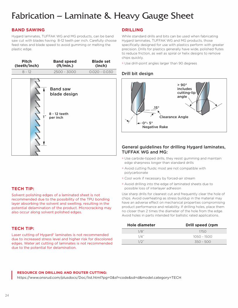
Hole diameter Drill speed (rpm) 1/8˝ 1750
1/4˝ 1050 - 1500
1/2˝ 350 - 500
Drill bit design
DRILLINGWhile standard drills and bits can be used when fabricating Hygard laminates, TUFFAK WG and MG products, those specifically designed for use with plastics perform with greater precision. Drills for plastics generally have wide, polished flutes to reduce friction, as well as spiral or helix designs to remove chips quickly.
» Use drill-point angles larger than 90 degrees
RESOURCE ON DRILLING AND ROUTER CUTTING:https://www.onsrud.com/plusdocs/Doc/list.html?pg=0&sf=code&sd=d&model.category=TECH
BAND SAWINGHygard laminates, TUFFAK WG and MG products, can be band saw cut with blades having 8-12 teeth per inch. Carefully choose feed rates and blade speed to avoid gumming or melting the plastic edge.
TECH TIP:Laser cutting of Hygard® laminates is not recommended due to increased stress level and higher risk for discolored edges. Water jet cutting of laminates is not recommended due to the potential for delamination.
General guidelines for drilling Hygard laminates, TUFFAK WG and MG:» Use carbide-tipped drills, they resist gumming and maintain edge sharpness longer than standard drills
» Avoid cutting fluids; most are not compatible with polycarbonate
» Cool work if necessary by forced-air stream
» Avoid drilling into the edge of laminated sheets due to possible loss of interlayer adhesion
Use sharp drills for cleanest cut and frequently clear the hole of chips. Avoid overheating as stress buildup in the material may have an adverse effect on mechanical properties compromising product performance and reliability. If drilling holes, place them no closer than 2 times the diameter of the hole from the edge. Avoid holes in parts intended for ballistic rated applications.
TECH TIP:Solvent polishing edges of a laminated sheet is not recommended due to the possibility of the TPU bonding layer absorbing the solvent and swelling, resulting in the potential delamination of the product. Microcracking may also occur along solvent polished edges.
1˝8 - 12 teethper inch
Pitch Band speed Blade set (teeth/inch) (ft/min.) (inch) 8 - 12 2500 - 3000 0.020 - 0.030
Band saw blade design
0°- 5°Negative Rake
Clearance Angle
.15°
> 90°includescutting-lipangle
25
Fabrication – Laminate & Heavy Gauge Sheet
FRAME DESIGN
Select a metal frame that matches the same level of security-rated protection as the specified Hygard laminate.
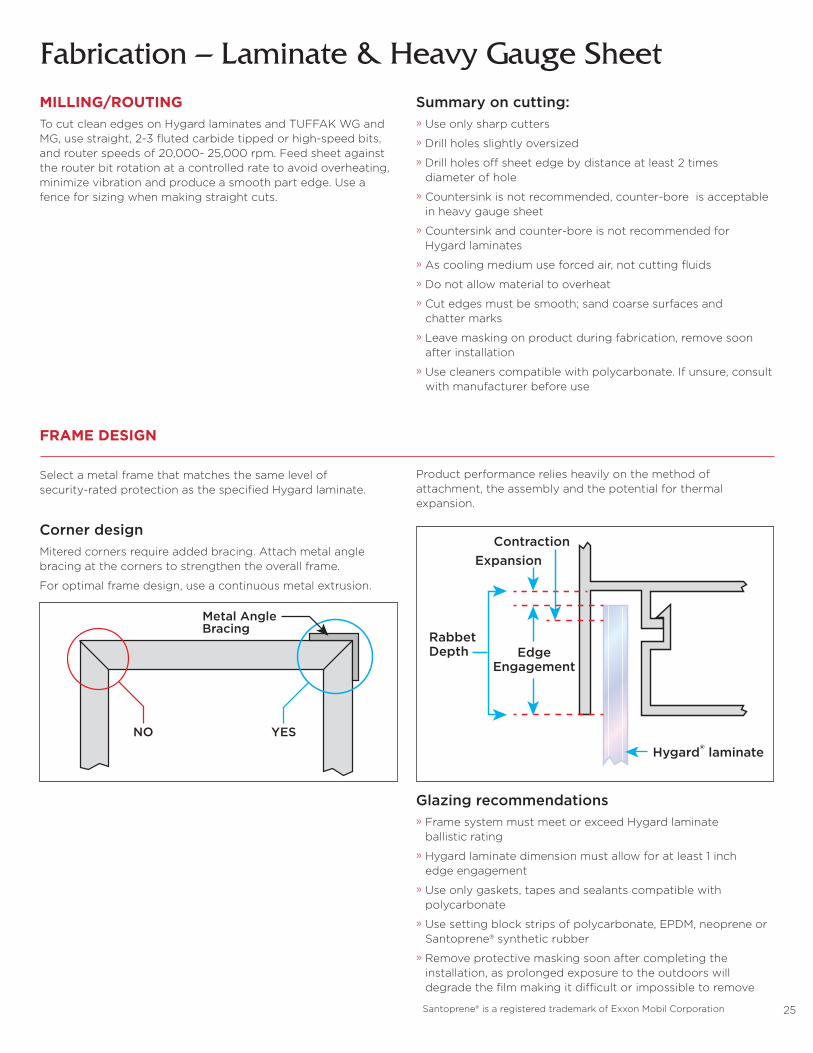
Corner designMitered corners require added bracing. Attach metal angle bracing at the corners to strengthen the overall frame.
For optimal frame design, use a continuous metal extrusion.
Product performance relies heavily on the method of attachment, the assembly and the potential for thermal expansion.
Glazing recommendations» Frame system must meet or exceed Hygard laminate ballistic rating
» Hygard laminate dimension must allow for at least 1 inch edge engagement
» Use only gaskets, tapes and sealants compatible with polycarbonate
» Use setting block strips of polycarbonate, EPDM, neoprene or Santoprene® synthetic rubber
» Remove protective masking soon after completing the installation, as prolonged exposure to the outdoors will degrade the film making it difficult or impossible to remove
Santoprene® is a registered trademark of Exxon Mobil Corporation
EdgeEngagement
ExpansionContraction
Hygard® laminate
RabbetDepth
NO YES
Metal AngleBracing
MILLING/ROUTINGTo cut clean edges on Hygard laminates and TUFFAK WG and MG, use straight, 2-3 fluted carbide tipped or high-speed bits, and router speeds of 20,000- 25,000 rpm. Feed sheet against the router bit rotation at a controlled rate to avoid overheating, minimize vibration and produce a smooth part edge. Use a fence for sizing when making straight cuts.
Summary on cutting:» Use only sharp cutters
» Drill holes slightly oversized
» Drill holes off sheet edge by distance at least 2 times diameter of hole
» Countersink is not recommended, counter-bore is acceptable in heavy gauge sheet
» Countersink and counter-bore is not recommended for Hygard laminates
» As cooling medium use forced air, not cutting fluids
» Do not allow material to overheat
» Cut edges must be smooth; sand coarse surfaces and chatter marks
» Leave masking on product during fabrication, remove soon after installation
» Use cleaners compatible with polycarbonate. If unsure, consult with manufacturer before use

26
Thermoforming

27
ThermoformingThermoforming is a cost-effective and practical processing method for producing three-dimensional shapes from a flat thermoplastic sheet using heat and pressure. Thermoformed parts can be found across transportation, signage, architectural, specialty and industrial markets.
PRODUCT GUIDE: FORMABILITY
Pre-drying TUFFAK sheetPrior to thermoforming, TUFFAK sheet must be pre-dried to prevent its physical properties from being compromised. Without pre-drying, the high processing temperatures may vaporize the small amount of moisture absorbed in the polycar-bonate, causing air bubbles or voids in the thermoformed part.
Pre-dry TUFFAK at 250°F in an air circulating oven equipped with a vent to properly discharge any moisture removed from the sheet. Drying at lower temperatures requires a longer time to thoroughly dry the sheet.
Remove the protective masking from the sheet prior to pre-drying, and hang or rack in the oven with a 1-inch separation to allow for adequate air exposure. Note; sheets stacked without air spacing will not dry. While properly dried TUFFAK sheets will remain dry for approximately eight hours (or less in humid climates and conditions), Plaskolite recommends that sheets be processed as soon as possible upon removal from the oven.
TUFFAK product Vacuum forming Drape forming Line bending
GP Q Q Q
DX-NR Q Q Q
FC – Q –
FI Q Q Q
LF Q Q Q
LD Q Q Q
Lumen XT Q Q Q
OP Q Q Q
NR Q Q Q
SL Q Q Q
SK Q Q Q
UV Q Q Q
Gauge 250°F 180°F 0.093˝ 4 8 0.118˝ 4 14 0.177˝ 12 30 0.236˝ 24 50
Drying times/hours
50
40
30
20
10
00.093˝ 0.118˝
Gauge
Ho
urs
0.177˝ 0.236˝
180°F
250°F
Known for its low tooling cost and moderate equipment investment, thermoforming is most economical where production volumes are 10,000 parts per year or less. It allows for great design flexibility, and serves as a practical means for prototyping and pre-production trialing of injection molded applications.
Registration or distortion thermoformingRegistration forming, also referred to as distortion thermo-forming, is the process of taking a distorted printed plastic sheet and vacuum forming the image or picture over the thermoformed mold. This allows the initial distorted image to appear in corresponding areas of mold resulting in a non-distorted, three-dimensional image.
28
Forming equipmentWhen setting up the thermoformer, ensure there is adequate clearance between the clamping frame and mold to allow for deep sheet sag. Optimize the platen speed and clamp frame to maximize the processing rate.
Recommended heater elements include ceramic, quartz and halogen. Calrods and nichrome elements can also be used, but typically do not perform as well for heating control. The most efficient thermoforming machines have both top and bottom heater banks for heating polycarbonate sheet. One-sided heating limits forming method options, and tends to overheat the sheet surface and lengthen cycle times. Zone heating allows different banks of heating coils to be controlled separately to produce even heating. Unbalanced heating can lead to a non-uniform temperature profile in the sheet and is evident by uneven sag of the sheet.
The thermoformer’s reserve vacuum tank must be of sufficient size, with a pump capable of generating and maintaining a vacuum of 20-inches Hg pressure throughout the thermoforming cycle.
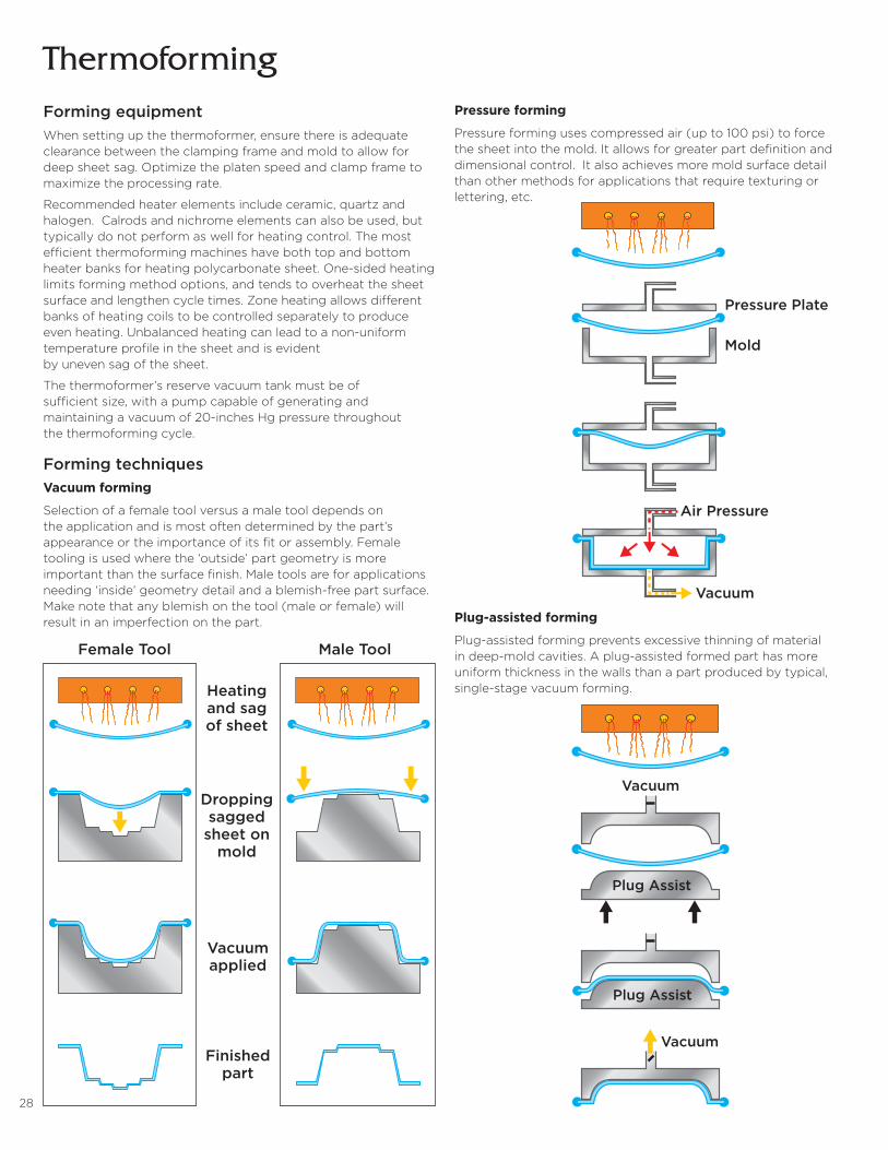
Forming techniquesVacuum forming
Selection of a female tool versus a male tool depends on the application and is most often determined by the part’s appearance or the importance of its fit or assembly. Female tooling is used where the ‘outside’ part geometry is more important than the surface finish. Male tools are for applications needing ‘inside’ geometry detail and a blemish-free part surface. Make note that any blemish on the tool (male or female) will result in an imperfection on the part.
Pressure forming
Pressure forming uses compressed air (up to 100 psi) to force the sheet into the mold. It allows for greater part definition and dimensional control. It also achieves more mold surface detail than other methods for applications that require texturing or lettering, etc.
Plug-assisted forming
Plug-assisted forming prevents excessive thinning of material in deep-mold cavities. A plug-assisted formed part has more uniform thickness in the walls than a part produced by typical, single-stage vacuum forming.
Thermoforming
Pressure Plate
Mold
Air Pressure
Vacuum
Vacuum
Vacuum
Plug Assist
Plug Assist
Female Tool
Dropping sagged
sheet on mold
Heating and sag of sheet
Vacuum applied
Finished part
Male Tool
29
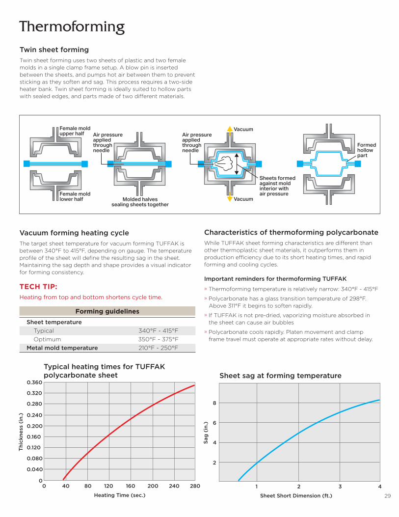
ThermoformingTwin sheet formingTwin sheet forming uses two sheets of plastic and two female molds in a single clamp frame setup. A blow pin is inserted between the sheets, and pumps hot air between them to prevent sticking as they soften and sag. This process requires a two-side heater bank. Twin sheet forming is ideally suited to hollow parts with sealed edges, and parts made of two different materials.
Vacuum forming heating cycleThe target sheet temperature for vacuum forming TUFFAK is between 340°F to 415°F, depending on gauge. The temperature profile of the sheet will define the resulting sag in the sheet. Maintaining the sag depth and shape provides a visual indicator for forming consistency.
Female moldupper half
Female moldlower half
Formedhollowpart
Molded halvessealing sheets together
Air pressureappliedthroughneedle
Sheets formedagainst moldinterior withair pressure
Vacuum
Vacuum
Air pressureappliedthroughneedle
Forming guidelines Sheet temperature Typical 340°F - 415°F Optimum 350°F - 375°F Metal mold temperature 210°F - 250°F
Characteristics of thermoforming polycarbonateWhile TUFFAK sheet forming characteristics are different than other thermoplastic sheet materials, it outperforms them in production efficiency due to its short heating times, and rapid forming and cooling cycles. Important reminders for thermoforming TUFFAK
» Thermoforming temperature is relatively narrow: 340°F - 415°F
» Polycarbonate has a glass transition temperature of 298°F. Above 311°F it begins to soften rapidly.
» If TUFFAK is not pre-dried, vaporizing moisture absorbed in the sheet can cause air bubbles
» Polycarbonate cools rapidly. Platen movement and clamp frame travel must operate at appropriate rates without delay.
0.360
0.320
0.280
0.240
0.200
Thi
ckne
ss (
in.)
Sag
(in
.)
0.160
0.120
0.080
0.040
00
1 2 3 4
8
6
4
2
40 80 120
Heating Time (sec.)
Sheet Short Dimension (ft.)
160 200 240 280
0.360
0.320
0.280
0.240
0.200
Thi
ckne
ss (
in.)
Sag
(in
.)
0.160
0.120
0.080
0.040
00
1 2 3 4
8
6
4
2
40 80 120
Heating Time (sec.)
Sheet Short Dimension (ft.)
160 200 240 280
Typical heating times for TUFFAK polycarbonate sheet Sheet sag at forming temperature
TECH TIP:Heating from top and bottom shortens cycle time.
30
MoldsExtremely durable and higher quality than their lower cost counterparts, aluminum molds are ideal for high volume and recurring production programs. However, for limited or small run volumes, less expensive mold materials like epoxy, fiberglass and wood may be more economical choices.
Note: Aluminum tools require internal heating to maintain a surface temperature of 210°F - 250°F.
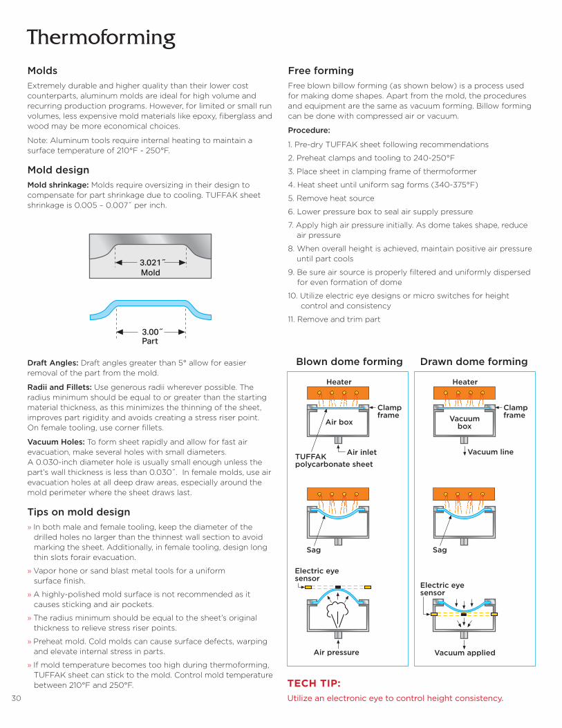
Mold designMold shrinkage: Molds require oversizing in their design to compensate for part shrinkage due to cooling. TUFFAK sheet shrinkage is 0.005 – 0.007˝ per inch.
Thermoforming
Draft Angles: Draft angles greater than 5° allow for easier removal of the part from the mold.
Radii and Fillets: Use generous radii wherever possible. The radius minimum should be equal to or greater than the starting material thickness, as this minimizes the thinning of the sheet, improves part rigidity and avoids creating a stress riser point. On female tooling, use corner fillets.
Vacuum Holes: To form sheet rapidly and allow for fast air evacuation, make several holes with small diameters. A 0.030-inch diameter hole is usually small enough unless the part’s wall thickness is less than 0.030˝. In female molds, use air evacuation holes at all deep draw areas, especially around the mold perimeter where the sheet draws last.
Tips on mold design» In both male and female tooling, keep the diameter of the drilled holes no larger than the thinnest wall section to avoid marking the sheet. Additionally, in female tooling, design long thin slots forair evacuation.
» Vapor hone or sand blast metal tools for a uniform surface finish.
» A highly-polished mold surface is not recommended as it causes sticking and air pockets.
» The radius minimum should be equal to the sheet’s original thickness to relieve stress riser points.
» Preheat mold. Cold molds can cause surface defects, warping and elevate internal stress in parts.
» If mold temperature becomes too high during thermoforming, TUFFAK sheet can stick to the mold. Control mold temperature between 210°F and 250°F.
Free formingFree blown billow forming (as shown below) is a process used for making dome shapes. Apart from the mold, the procedures and equipment are the same as vacuum forming. Billow forming can be done with compressed air or vacuum.
Procedure:
1. Pre-dry TUFFAK sheet following recommendations
2. Preheat clamps and tooling to 240-250°F
3. Place sheet in clamping frame of thermoformer
4. Heat sheet until uniform sag forms (340-375°F)
5. Remove heat source
6. Lower pressure box to seal air supply pressure
7. Apply high air pressure initially. As dome takes shape, reduce air pressure
8. When overall height is achieved, maintain positive air pressure until part cools
9. Be sure air source is properly filtered and uniformly dispersed for even formation of dome
10. Utilize electric eye designs or micro switches for height control and consistency
11. Remove and trim part
3.021˝
Mold
3.00˝Part
Heater
Clampframe
Air box
Air inlet
Air pressure
Electric eyesensor
Electric eyesensor
TUFFAKpolycarbonate sheet
Sag
Heater
ClampframeVacuum
box
Vacuum line
Vacuum applied
Sag
Heater
Clampframe
Air box
Air inlet
Air pressure
Electric eyesensor
Electric eyesensor
TUFFAKpolycarbonate sheet
Sag
Heater
ClampframeVacuum
box
Vacuum line
Vacuum applied
Sag
Blown dome forming Drawn dome forming
TECH TIP:Utilize an electronic eye to control height consistency.

31
ThermoformingDrape formingDrape forming requires a felt covered wood tool for making a single radius of curvature parts, or designs of slight contours. Face shields and recreational vehicle windscreens are examples of parts made by this method. The sheet is typically heated on an oven shelf or other means of supporting sheet.
Procedure:
1. Pre-drying TUFFAK sheet is not typically required in drape forming
2. High quality, reproducible forming requires consistent orientation in handling and cutting (top versus bottom), as well as extrusion direction. Do not flip or rotate sheets.
3. Heat oven at 320°F-325°F
4. Locate the oven shelf at the midpoint of the oven for optimum heat balance. Place a felt covered piece of plywood or other flat rigid, heat-resistant sheet on the oven rack or on a portable oven dolly. Be sure to use a fabric cover to protect the sheet from scratches.
5. Bring TUFFAK sheet to forming temperature in the oven at 320-325°F. Depending on gauge, this may take several minutes. For example, 0.118˝gauge sheet takes approximately 3-5 minutes.
6. Manually remove the heated sheet from the oven, and immediately position it over the felt covered mold.
7. Apply pressure at the edges of the sheet to help the sheet take the form of the mold or use matched molds (clamshell molds). Cooling takes about 30-60 seconds.
8. Always wear thermal gloves when handling hot sheet, holding the material by its edges.
Line bending or strip heatingLine bending, also referred to as strip heating, is a technique for producing linear bends. Generally, pre-drying is not required for line bending TUFFAK sheet gauges up to 0.177˝. For thicker sheets, back routing or V-grooving along the bend line is recommended.
Procedure:
1. Remove protective masking in bend area
2. Regulate heating element to 340°F - 365°F
3. Place sheet over heating element at bend area
4. Allow heat to soften material. The amount of time depends on gauge
5. Remove sheet and make desired bend on a felt covered fixture
6. Bend immediately as polycarbonate cools quickly
7. Allow part to cool on the fixture until set up - about 30 seconds
Note: Some bends may require a degree of over-bend to achieve desired angle.
Force
Male Mold
Female Mold
Milled groove to accept Nichromewire (approximately 1/16 - 1/8˝ belowsurface of TUFFAK sheet). Do notallow wire to contact sheet directly.
Nichromeresistance wire(or Calrod typeheater)
V-groovingradius (1/16˝)
Back routingradius (1/16˝)
Heat bending device
TECH TIPS:» Line bending works best for lengths of 24˝ or shorter. Longer dimensions require preheating the entire piece to 200°F first to prevent warping. » For best results with gauges greater than 0.177˝, use two-side heating, or turn the part frequently when using a one-side heater. This helps with even heat penetration, preventing moisture bubbling. » Additionally, for gauges greater than 0.177˝, back route or V-groove with a 1/16-inch radius to heat cross section. Again, this will help avoid moisture bubbling, while still creating a sharp angle.
Typical representation of thermoformed part

32
Troubleshooting Guide
33
Troubleshooting guide
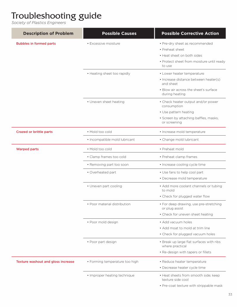
Description of Problem Possible Causes Possible Corrective Action
Bubbles in formed parts •Excessivemoisture •Pre-drysheetasrecommended
•Preheatsheet
•Heatsheetonbothsides
•Protectsheetfrommoistureuntilready to use
•Heatingsheettoorapidly •Lowerheatertemperature
•Increasedistancebetweenheater(s) and sheet
•Blowairacrossthesheet’ssurface during heating
•Unevensheetheating •Checkheateroutputand/orpower consumption
•Usepatternheating
•Screenbyattachingbaffles,masks, or screening
Crazed or brittle parts •Moldtoocold •Increasemoldtemperature
•Incompatiblemoldlubricant •Changemoldlubricant
Warped parts •Moldtoocold •Preheatmold
•Clampframestoocold •Preheatclampframes
•Removingparttoosoon •Increasecoolingcycletime
•Overheatedpart •Usefanstohelpcoolpart
•Decreasemoldtemperature
•Unevenpartcooling •Addmorecoolantchannelsortubing to mold
•Checkforpluggedwaterflow
•Poormaterialdistribution •Fordeepdrawing,usepre-stretching or plug assist
•Checkforunevensheetheating
•Poormolddesign •Addvacuumholes
•Addmoattomoldattrimline
•Checkforpluggedvacuumholes
•Poorpartdesign •Breakuplargeflatsurfaceswithribs where practical
•Re-designwithtapersorfillets
Texture washout and gloss increase •Formingtemperaturetoohigh •Reduceheatertemperature
•Decreaseheatercycletime
•Improperheatingtechnique •Heatsheetsfromsmoothside;keep texture side cool
•Pre-coattexturewithstrippablemask
Society of Plastics Engineers
34
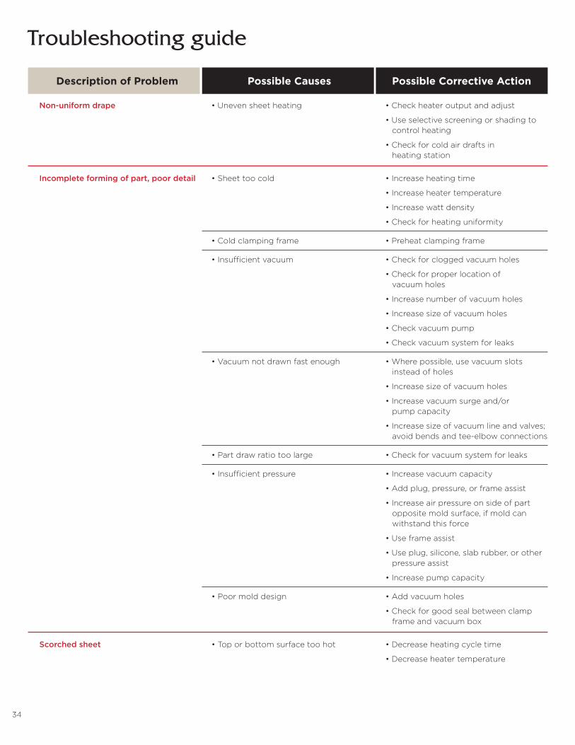
Troubleshooting guide
Non-uniform drape •Unevensheetheating •Checkheateroutputandadjust
•Useselectivescreeningorshadingto control heating
•Checkforcoldairdraftsin heating station
Incomplete forming of part, poor detail •Sheettoocold •Increaseheatingtime
•Increaseheatertemperature
•Increasewattdensity
•Checkforheatinguniformity
•Coldclampingframe •Preheatclampingframe
•Insufficientvacuum •Checkforcloggedvacuumholes
•Checkforproperlocationof vacuum holes
•Increasenumberofvacuumholes
•Increasesizeofvacuumholes
•Checkvacuumpump
•Checkvacuumsystemforleaks
•Vacuumnotdrawnfastenough •Wherepossible,usevacuumslots instead of holes
•Increasesizeofvacuumholes
•Increasevacuumsurgeand/or pump capacity
•Increasesizeofvacuumlineandvalves; avoid bends and tee-elbow connections
•Partdrawratiotoolarge •Checkforvacuumsystemforleaks
•Insufficientpressure •Increasevacuumcapacity
•Addplug,pressure,orframeassist
•Increaseairpressureonsideofpart opposite mold surface, if mold can withstand this force
•Useframeassist
•Useplug,silicone,slabrubber,orother pressure assist
•Increasepumpcapacity
•Poormolddesign •Addvacuumholes
•Checkforgoodsealbetweenclamp frame and vacuum box
Scorched sheet •Toporbottomsurfacetoohot •Decreaseheatingcycletime
•Decreaseheatertemperature
Description of Problem Possible Causes Possible Corrective Action

35
Troubleshooting guide
Poor surface finish •Moldsurfacetoorough •Draw-polishmoldorusemold material better suited to mold service requirements
•Moldmark-off •Usepowderedmoldlubricant sparingly
•Draftangletooshallow •Increasedraftangle
•Airentrapmentoversmooth •Grit-blastmoldsurface moldsurface •Addvacuumholesinaffectedarea
•Insufficientvacuum •Addvacuumholes
•Checkforproperlocationof vacuum holes
•Checkvacuumsystemforleaks
•Checkforpluggedvacuumholes
•Moldtoohot •Decreasemoldtemperature
•Moldtoocold •Increasemoldtemperature
•Dirtysheet •Cleansheetwithdeionizingairgun
•Dirtymold •Cleanmoldwithdeionizingairgun
•Dustinatmosphere •Cleanthermoformingarea
•Isolatethermoformingareaand filter air
•Scratchedsheet •Polishsheet
Loss of color •Overdrawnsheet(Parttoothin) •Increasesheetgauge
•Increasesheettemperature
•Usepre-draw
•Useplugassistfordeep-drawparts
Description of Problem Possible Causes Possible Corrective Action
36
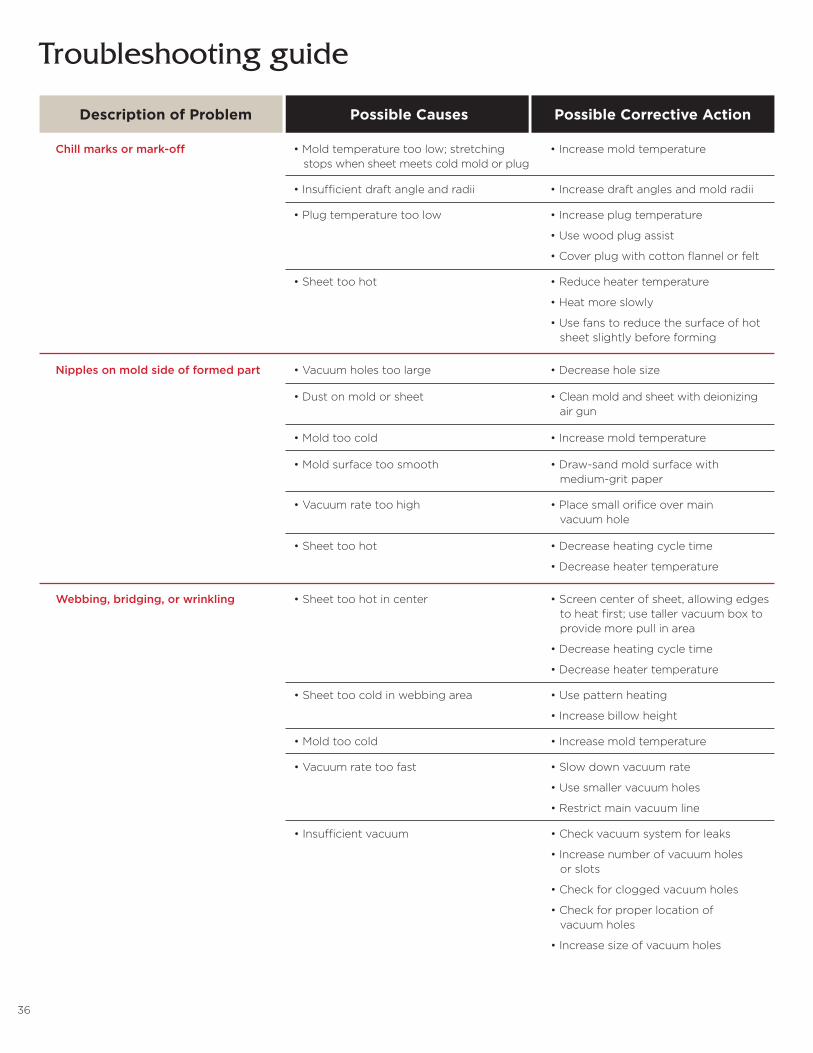
Chill marks or mark-off •Moldtemperaturetoolow;stretching •Increasemoldtemperature stops when sheet meets cold mold or plug
•Insufficientdraftangleandradii •Increasedraftanglesandmoldradii
•Plugtemperaturetoolow •Increaseplugtemperature
•Usewoodplugassist
•Coverplugwithcottonflannelorfelt
•Sheettoohot •Reduceheatertemperature
•Heatmoreslowly
•Usefanstoreducethesurfaceofhot sheet slightly before forming
Nipples on mold side of formed part •Vacuumholestoolarge •Decreaseholesize
•Dustonmoldorsheet •Cleanmoldandsheetwithdeionizing air gun
•Moldtoocold •Increasemoldtemperature
•Moldsurfacetoosmooth •Draw-sandmoldsurfacewith medium-grit paper
•Vacuumratetoohigh •Placesmallorificeovermain vacuum hole
•Sheettoohot •Decreaseheatingcycletime
•Decreaseheatertemperature
Webbing, bridging, or wrinkling •Sheettoohotincenter •Screencenterofsheet,allowingedges to heat first; use taller vacuum box to provide more pull in area
•Decreaseheatingcycletime
•Decreaseheatertemperature
•Sheettoocoldinwebbingarea •Usepatternheating
•Increasebillowheight
•Moldtoocold •Increasemoldtemperature
•Vacuumratetoofast •Slowdownvacuumrate
•Usesmallervacuumholes
•Restrictmainvacuumline
•Insufficientvacuum •Checkvacuumsystemforleaks
•Increasenumberofvacuumholes or slots
•Checkforcloggedvacuumholes
•Checkforproperlocationof vacuum holes
•Increasesizeofvacuumholes
Troubleshooting guide
Description of Problem Possible Causes Possible Corrective Action
37
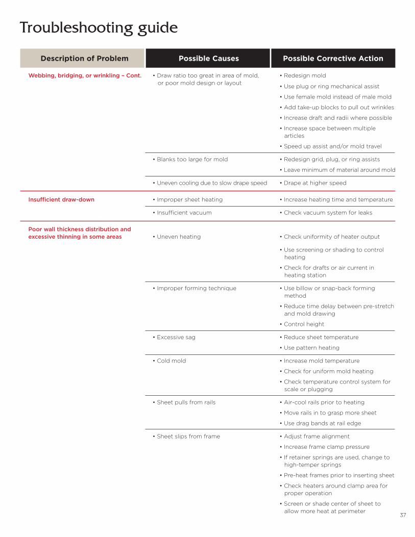
Webbing, bridging, or wrinkling – Cont. •Drawratiotoogreatinareaofmold, •Redesignmold or poor mold design or layout
•Useplugorringmechanicalassist
•Usefemalemoldinsteadofmalemold
•Addtake-upblockstopulloutwrinkles
•Increasedraftandradiiwherepossible
•Increasespacebetweenmultiple articles
•Speedupassistand/ormoldtravel
•Blankstoolargeformold •Redesigngrid,plug,orringassists
•Leaveminimumofmaterialaroundmold
•Unevencoolingduetoslowdrapespeed •Drapeathigherspeed
Insufficient draw-down •Impropersheetheating •Increaseheatingtimeandtemperature
•Insufficientvacuum •Checkvacuumsystemforleaks
Poor wall thickness distribution and excessive thinning in some areas •Unevenheating •Checkuniformityofheateroutput
•Usescreeningorshadingtocontrol heating
•Checkfordraftsoraircurrentin heating station
•Improperformingtechnique •Usebilloworsnap-backforming method
•Reducetimedelaybetweenpre-stretch and mold drawing
•Controlheight
•Excessivesag •Reducesheettemperature
•Usepatternheating
•Coldmold •Increasemoldtemperature
•Checkforuniformmoldheating
•Checktemperaturecontrolsystemfor scale or plugging
•Sheetpullsfromrails •Air-coolrailspriortoheating
•Moverailsintograspmoresheet
•Usedragbandsatrailedge
•Sheetslipsfromframe •Adjustframealignment
•Increaseframeclamppressure
•Ifretainerspringsareused,changeto high-temper springs
•Pre-heatframespriortoinsertingsheet
•Checkheatersaroundclampareafor proper operation
•Screenorshadecenterofsheetto allow more heat at perimeter
Troubleshooting guide
Description of Problem Possible Causes Possible Corrective Action
38
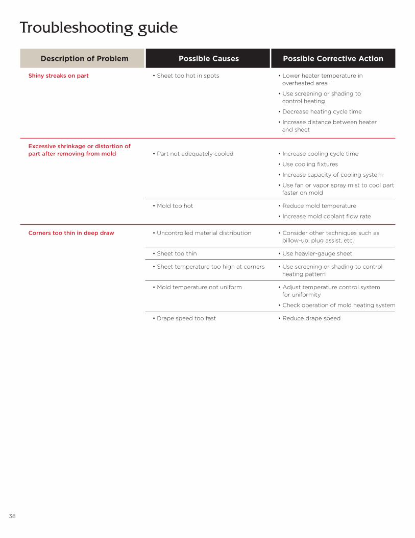
Shiny streaks on part •Sheettoohotinspots •Lowerheatertemperaturein overheated area
•Usescreeningorshadingto control heating
•Decreaseheatingcycletime
•Increasedistancebetweenheater and sheet
Excessive shrinkage or distortion of part after removing from mold •Partnotadequatelycooled •Increasecoolingcycletime
•Usecoolingfixtures
•Increasecapacityofcoolingsystem
•Usefanorvaporspraymisttocoolpart faster on mold
•Moldtoohot •Reducemoldtemperature
•Increasemoldcoolantflowrate
Corners too thin in deep draw •Uncontrolledmaterialdistribution •Considerothertechniquessuchas billow-up, plug assist, etc.
•Sheettoothin •Useheavier-gaugesheet
•Sheettemperaturetoohighatcorners •Usescreeningorshadingtocontrol heating pattern
•Moldtemperaturenotuniform •Adjusttemperaturecontrolsystem for uniformity
•Checkoperationofmoldheatingsystem
•Drapespeedtoofast •Reducedrapespeed
Troubleshooting guide
Description of Problem Possible Causes Possible Corrective Action
39
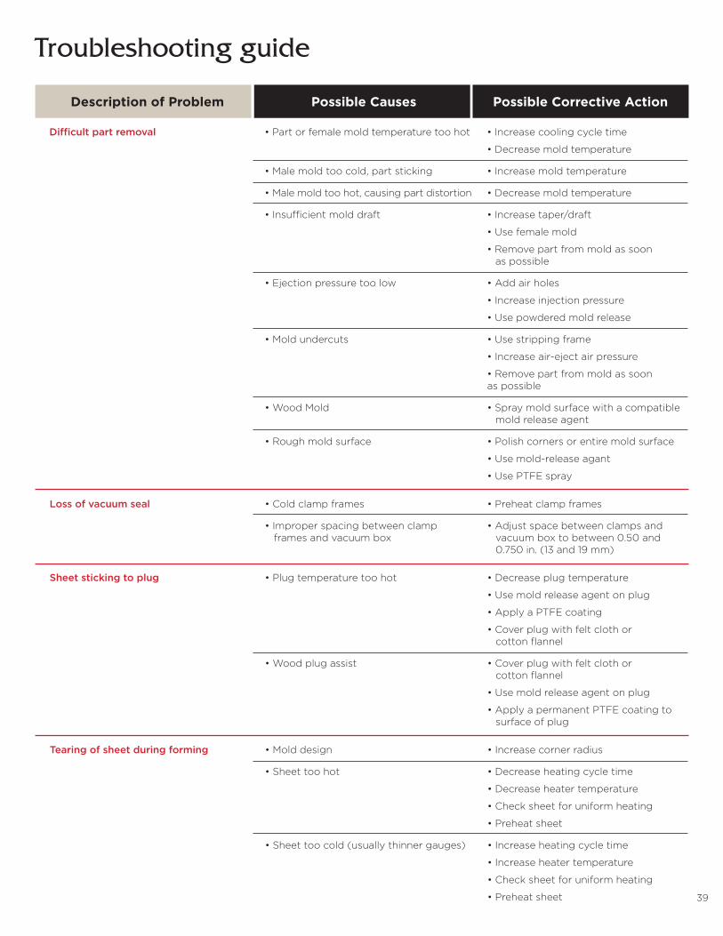
Difficult part removal •Partorfemalemoldtemperaturetoohot •Increasecoolingcycletime
•Decreasemoldtemperature
•Malemoldtoocold,partsticking •Increasemoldtemperature
•Malemoldtoohot,causingpartdistortion •Decreasemoldtemperature
•Insufficientmolddraft •Increasetaper/draft
•Usefemalemold
•Removepartfrommoldassoon as possible
•Ejectionpressuretoolow •Addairholes
•Increaseinjectionpressure
•Usepowderedmoldrelease
•Moldundercuts •Usestrippingframe
•Increaseair-ejectairpressure
•Removepartfrommoldassoon as possible
•WoodMold •Spraymoldsurfacewithacompatible mold release agent
•Roughmoldsurface •Polishcornersorentiremoldsurface
•Usemold-releaseagant
•UsePTFEspray
Loss of vacuum seal •Coldclampframes •Preheatclampframes
•Improperspacingbetweenclamp •Adjustspacebetweenclampsand frames and vacuum box vacuum box to between 0.50 and 0.750 in. (13 and 19 mm)
Sheet sticking to plug •Plugtemperaturetoohot •Decreaseplugtemperature
•Usemoldreleaseagentonplug
•ApplyaPTFEcoating
•Coverplugwithfeltclothor cotton flannel
•Woodplugassist •Coverplugwithfeltclothor cotton flannel
•Usemoldreleaseagentonplug
•ApplyapermanentPTFEcoatingto surface of plug
Tearing of sheet during forming •Molddesign •Increasecornerradius
•Sheettoohot •Decreaseheatingcycletime
•Decreaseheatertemperature
•Checksheetforuniformheating
•Preheatsheet
•Sheettoocold(usuallythinnergauges) •Increaseheatingcycletime
•Increaseheatertemperature
•Checksheetforuniformheating
•Preheatsheet
Troubleshooting guide
Description of Problem Possible Causes Possible Corrective Action
40
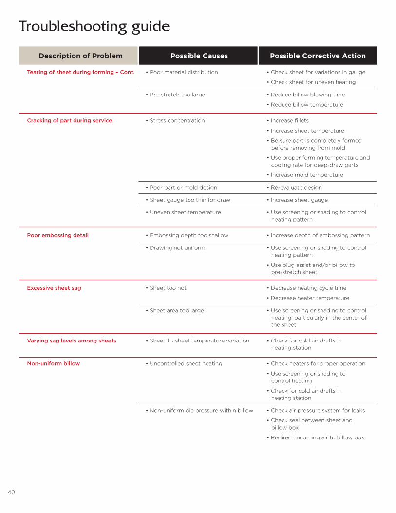
Tearing of sheet during forming – Cont. •Poormaterialdistribution •Checksheetforvariationsingauge
•Checksheetforunevenheating
•Pre-stretchtoolarge •Reducebillowblowingtime
•Reducebillowtemperature
Cracking of part during service •Stressconcentration •Increasefillets
•Increasesheettemperature
•Besurepartiscompletelyformed before removing from mold
•Useproperformingtemperatureand cooling rate for deep-draw parts
•Increasemoldtemperature
•Poorpartormolddesign •Re-evaluatedesign
•Sheetgaugetoothinfordraw •Increasesheetgauge
•Unevensheettemperature •Usescreeningorshadingtocontrol heating pattern
Poor embossing detail •Embossingdepthtooshallow •Increasedepthofembossingpattern
•Drawingnotuniform •Usescreeningorshadingtocontrol heating pattern
•Useplugassistand/orbillowto pre-stretch sheet
Excessive sheet sag •Sheettoohot •Decreaseheatingcycletime
•Decreaseheatertemperature
•Sheetareatoolarge •Usescreeningorshadingtocontrol heating, particularly in the center of the sheet.
Varying sag levels among sheets •Sheet-to-sheettemperaturevariation •Checkforcoldairdraftsin heating station
Non-uniform billow •Uncontrolledsheetheating •Checkheatersforproperoperation
•Usescreeningorshadingto control heating
•Checkforcoldairdraftsin heating station
•Non-uniformdiepressurewithinbillow •Checkairpressuresystemforleaks
•Checksealbetweensheetand billow box
•Redirectincomingairtobillowbox
Troubleshooting guide
Description of Problem Possible Causes Possible Corrective Action

41
Brake Bending, Cold Forming,
Annealing
42
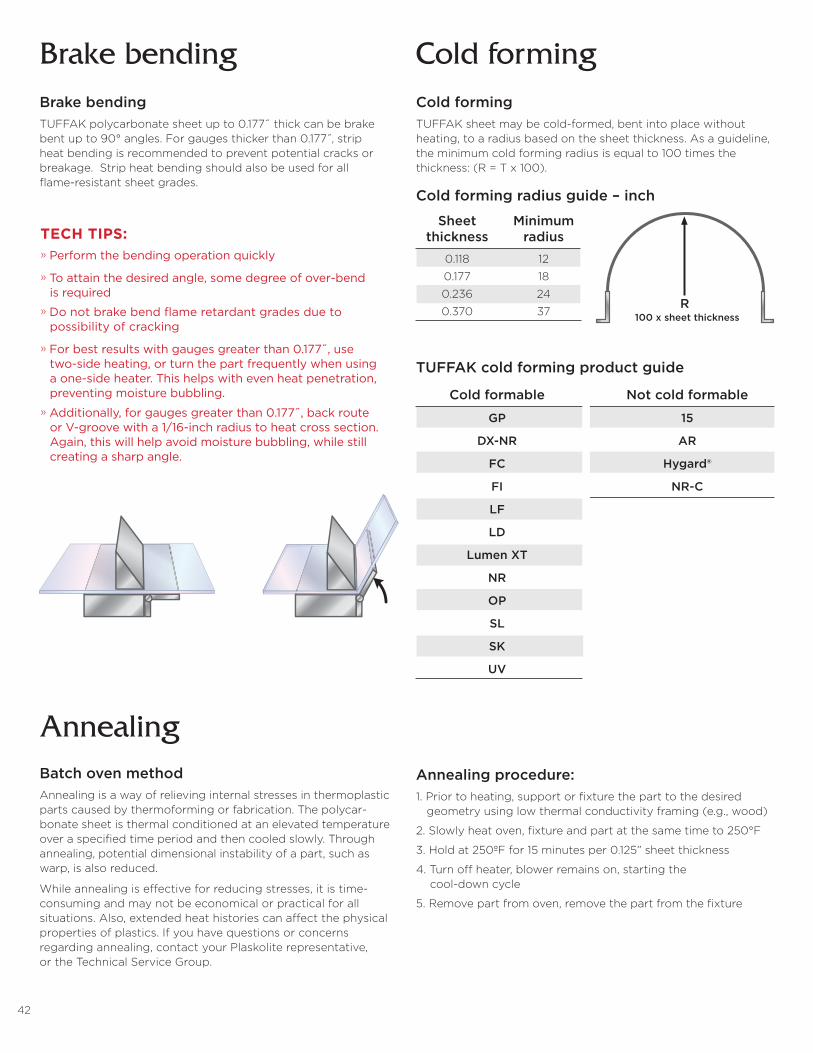
Brake bending Cold formingBrake bendingTUFFAK polycarbonate sheet up to 0.177˝ thick can be brake bent up to 90° angles. For gauges thicker than 0.177 ,̋ strip heat bending is recommended to prevent potential cracks or breakage. Strip heat bending should also be used for all flame-resistant sheet grades.
Cold formingTUFFAK sheet may be cold-formed, bent into place without heating, to a radius based on the sheet thickness. As a guideline, the minimum cold forming radius is equal to 100 times the thickness: (R = T x 100).
Sheet Minimum thickness radius
0.118 12
0.177 18
0.236 24
0.370 37
Cold formable Not cold formable
GP 15
DX-NR AR
FC Hygard®
FI NR-C
LF
LD
Lumen XT
NR
OP
SL
SK
UV
Cold forming radius guide – inch
TUFFAK cold forming product guide
R100 x sheet thickness
AnnealingBatch oven methodAnnealing is a way of relieving internal stresses in thermoplastic parts caused by thermoforming or fabrication. The polycar-bonate sheet is thermal conditioned at an elevated temperature over a specified time period and then cooled slowly. Through annealing, potential dimensional instability of a part, such as warp, is also reduced.
While annealing is effective for reducing stresses, it is time-consuming and may not be economical or practical for all situations. Also, extended heat histories can affect the physical properties of plastics. If you have questions or concerns regarding annealing, contact your Plaskolite representative, or the Technical Service Group.
Annealing procedure:1. Prior to heating, support or fixture the part to the desired geometry using low thermal conductivity framing (e.g., wood)
2. Slowly heat oven, fixture and part at the same time to 250°F
3. Hold at 250ºF for 15 minutes per 0.125” sheet thickness
4. Turn off heater, blower remains on, starting the cool-down cycle
5. Remove part from oven, remove the part from the fixture
TECH TIPS:» Perform the bending operation quickly
» To attain the desired angle, some degree of over-bend is required» Do not brake bend flame retardant grades due to possibility of cracking
» For best results with gauges greater than 0.177˝, use two-side heating, or turn the part frequently when using a one-side heater. This helps with even heat penetration, preventing moisture bubbling. » Additionally, for gauges greater than 0.177˝, back route or V-groove with a 1/16-inch radius to heat cross section. Again, this will help avoid moisture bubbling, while still creating a sharp angle.

43
Bonding Applications

44
Bonding ApplicationsSolvent bondingSolvent bonding joins one plastic to itself or another type of plastic that dissolves in the same solvent. Typically, this process involves treating the bonding area with the minimum amount of solvent needed to soften the surfaces and then clamping the parts together until they bond.
Methylene chloride or ethylene dichloride bonds TUFFAK sheet to itself. Methylene chloride’s fast evaporation rate helps to prevent solvent vapor entrapment for simple assemblies. For complex assemblies that require more curing time, use ethylene dichloride. A 60/40 mixture of methylene chloride and ethylene dichloride will allow for longer a time to assemble parts than pure methylene chloride.
Expect brittleness and reduced impact strength at the bonded joints.
Note: Wear proper protective equipment when working with chemicals. Adequate ventilation is essential.
Review Safety Data Sheet from product manufacturer and control exposure according to OSHA guidelines.
Bonding procedure1. For optimum bonding, confirm the parts mate flush. This helps to ensure uniform pressure distribution across the entire bond area.
2. Clean joint surfaces with isopropyl alcohol.
3. Use fresh solvent.
4. For best results, avoid using excessive solvent - it causes bubbling and “squeeze-out,” which decreases bond strength.
5. Apply a thin bead of solvent using a needle applicator; the capillary action will pull the solvent into the joint interface.
6. For large parts, it may be easier to use a shallow pan containing enough solvent to cover the edge of the bonding part.
7. Dip part into pan, wetting its edge.
8. Transfer onto mating part.
9. Apply pressure to the mating parts.
10. Hold fixture for a minimum of 60 seconds.
11. The bonded part is now safe to handle.
Avoid whitening of bond» Use fresh solvent whenever possible. Once a container is opened, the solvent can absorb moisture from the air over time. Wet solvent can cause a cloudy bond.
» Fabricate in a climate controlled area with low relative humidity.
» Add 10% glacial acetic acid to a container of previously opened solvent to help reduce whitening.
» Add 5-10% polycarbonate shavings to the solvent to help slow cure time and reduce whitening.
Adhesive bondingAdhesive bonding systems are among the most robust for joining plastic parts to parts made of the same plastic, different plastics or non-plastic materials. Generally, adhesives produce more consistent and predictable results in joints requiring strength and durability than other joining methods.
Consider the following when selecting an adhesive bonding material:» Chemical compatibility with TUFFAK sheet
» Flexibility or rigidity requirements
» Load bearing force
» Environmental condition and temperature requirements
» Aesthetics
General characterizations of different adhesive systems:» In general, urethane and epoxy adhesives impart excellent bond strength.
» UV-cured adhesives, attractive for curing in seconds, provide high bond strength.
» Silicone adhesives have flexible, strong bonds.
» Foamed adhesive tapes are known for strength and durable performance.
» Hot melts provide quick set times where high bond strength is not required.
» Use care in selecting adhesives, as some can be aggressive toward TUFFAK sheet.
Typical Butt-T Joint Design
TECH TIPS:» A fully cured joint requires 24-48 hours drying time
» Always cure parts in a well-ventilated area; never in an enclosed space. Trapped methylene chloride vapors chemically attack polycarbonate, reducing its physical properties.
» A 5-10% solution of polycarbonate shavings dissolved in methylene chloride helps to produce a smooth, filled joint and improves strength. For critical applications requiring more durability consider an adhesive product.
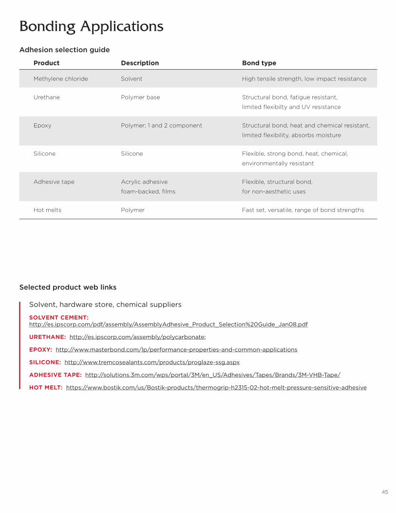
45
Bonding Applications
Product Description Bond type
Methylene chloride Solvent High tensile strength, low impact resistance
Urethane Polymer base Structural bond, fatigue resistant,
limited flexibilty and UV resistance
Epoxy Polymer; 1 and 2 component Structural bond, heat and chemical resistant,
limited flexibility, absorbs moisture
Silicone Silicone Flexible, strong bond, heat, chemical,
environmentally resistant
Adhesive tape Acrylic adhesive Flexible, structural bond,
foam-backed, films for non-aesthetic uses
Hot melts Polymer Fast set, versatile, range of bond strengths
Adhesion selection guide
Selected product web links
Solvent, hardware store, chemical suppliers
SOLVENT CEMENT: http://es.ipscorp.com/pdf/assembly/AssemblyAdhesive_Product_Selection%20Guide_Jan08.pdf
URETHANE: http://es.ipscorp.com/assembly/polycarbonate;
EPOXY: http://www.masterbond.com/lp/performance-properties-and-common-applications
SILICONE: http://www.tremcosealants.com/products/proglaze-ssg.aspx
ADHESIVE TAPE: http://solutions.3m.com/wps/portal/3M/en_US/Adhesives/Tapes/Brands/3M-VHB-Tape/
HOT MELT: https://www.bostik.com/us/Bostik-products/thermogrip-h2315-02-hot-melt-pressure-sensitive-adhesive

46
Mechanical Fastening
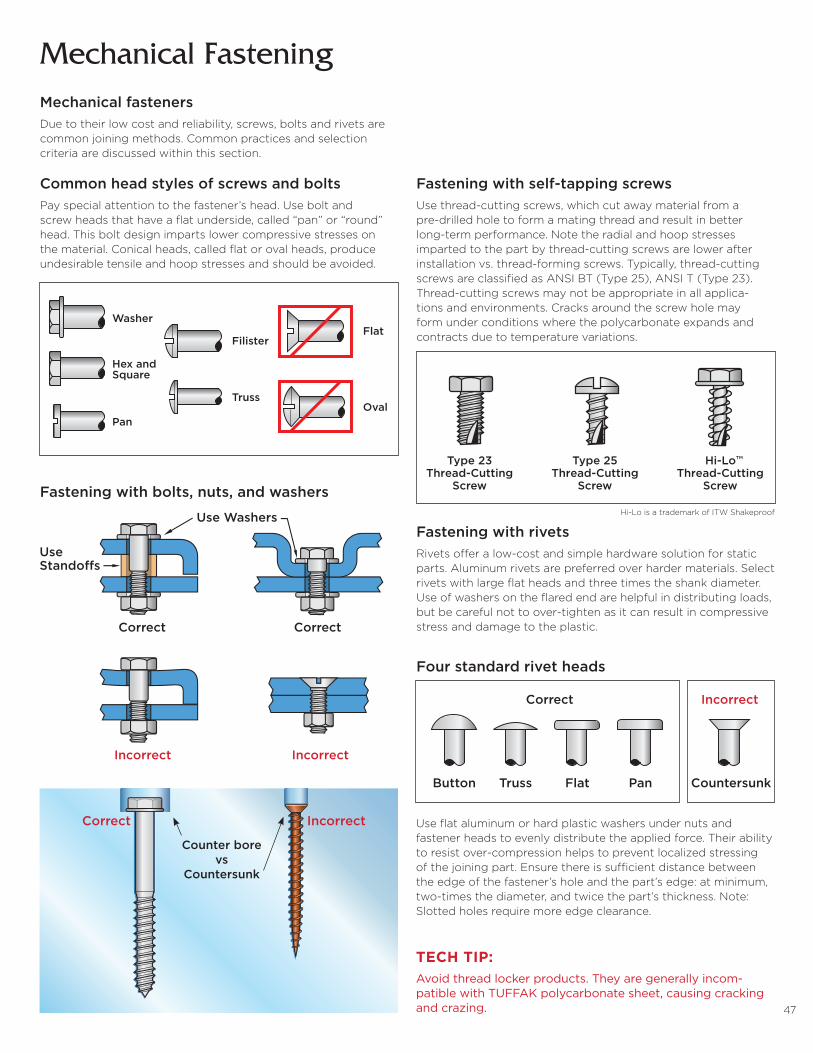
47
Mechanical FasteningMechanical fastenersDue to their low cost and reliability, screws, bolts and rivets are common joining methods. Common practices and selection criteria are discussed within this section.
Common head styles of screws and boltsPay special attention to the fastener’s head. Use bolt and screw heads that have a flat underside, called “pan” or “round” head. This bolt design imparts lower compressive stresses on the material. Conical heads, called flat or oval heads, produce undesirable tensile and hoop stresses and should be avoided.
Fastening with bolts, nuts, and washers
Washer
Hex andSquare
Pan
Filister
Truss
Flat
Oval
Incorrect
Correct
UseStando�s
Use Washers
Correct
Incorrect
Use flat aluminum or hard plastic washers under nuts and fastener heads to evenly distribute the applied force. Their ability to resist over-compression helps to prevent localized stressing of the joining part. Ensure there is sufficient distance between the edge of the fastener’s hole and the part’s edge: at minimum, two-times the diameter, and twice the part’s thickness. Note: Slotted holes require more edge clearance.
Fastening with self-tapping screwsUse thread-cutting screws, which cut away material from a pre-drilled hole to form a mating thread and result in better long-term performance. Note the radial and hoop stresses imparted to the part by thread-cutting screws are lower after installation vs. thread-forming screws. Typically, thread-cutting screws are classified as ANSI BT (Type 25), ANSI T (Type 23). Thread-cutting screws may not be appropriate in all applica-tions and environments. Cracks around the screw hole may form under conditions where the polycarbonate expands and contracts due to temperature variations.
Four standard rivet heads
Type 23Thread-Cutting
Screw
Type 25Thread-Cutting
Screw
Hi-Lo™Thread-Cutting
Screw
Fastening with rivetsRivets offer a low-cost and simple hardware solution for static parts. Aluminum rivets are preferred over harder materials. Select rivets with large flat heads and three times the shank diameter. Use of washers on the flared end are helpful in distributing loads, but be careful not to over-tighten as it can result in compressive stress and damage to the plastic.
Button Truss Flat Pan Countersunk
IncorrectCorrect
Button Truss Flat Pan Countersunk
IncorrectCorrect
Hi-Lo is a trademark of ITW Shakeproof
TECH TIP:Avoid thread locker products. They are generally incom-patible with TUFFAK polycarbonate sheet, causing cracking and crazing.
Correct Incorrect
Counter bore vs
Countersunk

48
Mechanical FasteningJoining dissimilar materialsFor assemblies constructed of a combination of TUFFAK sheet and metal (two dissimilar materials), it is important to design for thermal movement behavior. When heated, the plastic may buckle, due to its higher thermal expansion rate. Conversely, when cooled, the greater thermal shrinkage of plastic will cause strain-induced stress and may exceed the plastic’s working limit. This could lead to part failure.
The figure to the right shows a plastic part fastened to a metal component. As the ambient temperature rises, the plastic will expand more than the metal because the plastic’s coefficient of linear thermal expansion is four times higher.
For applications where wide temperature variations exist, use slotted screw holes in the plastic part. When joining plastic and metal parts, do not tighten fasteners to the point where joint friction and compressive loads prevent relative movement. If the fasteners are too tight it negates the effect of the slotted holes.
Factors to consider when joining plastic and metal parts:
» The size of the parts to be joined
» The magnitude of the temperature range
» The relative thermal expansion coefficients of the materials used in the part
Metal Bracket
TUFFAK Panel
Slotted Holes
MetalBracket
No allowance for expansion
Slotted hole allows for expansion
Metal Part
SlottedHole
SoftWasher
Fastener
The slotted hole could be ineither piece, as long asrelative movement is allowed.
There are many “J” clipsand fasteners that will allowrelative movement in assemblies.
TUFFAK Part
Allow for relative movement in assemblies of dissimilar materials
Restricted assembly design, not recommended
Example 1: Calculate the change in length for a 96 inch part that is constructed at 70° F, but will see operating temperatures up to 120° F
∆L = (plastic CLTE – metal CLTE) * temperature change * length of part (0.000038 – 0.000013)*50*96 . . . . . ∆L = 0.120 inches
Therefore, the design has to accommodate a growth of 0.12 inches.
Example 2: How much shrinkage will the same part see at -20° F
∆L = (plastic CLTE – metal CLTE) * temperature change * length of part (0.000038 – 0.000013)*90*96 . . . . . ∆L = 0.216 inches
Therefore, the design has to accommodate a contraction of 0.216 inches.
Coefficient of Linear Thermal Expansion (CLTE) values for materials
INCORRECTCORRECT
Material CTLE (105 in/in/°F) TUFFAK 3.8
Aluminum 1.3

49
Mechanical Fastening
Dukane Corp. http://www.dukane.com/us/PPL_upa.htm
Forward Technology Industries, Inc. http://www.forwardtech.com/plastic-assembly
Herrmann Ultrasonics, Inc. http://www.herrmannultrasonics.com/en-us
Ultra Sonic Seal Co. http://www.ultrasonicseal.com/upa/upa_tooling.html
For more information on ultrasonic joining techniques contact:
Ultrasonic weldingAn ultrasonic welder has two primary parts: a horn and a nest. The horn typically presses down on the upper plastic part (of the two to be welded), clamping the two parts together. The nest supports the bottom plastic part to prevent it from moving. The horn is vibrated ultrasonically for a preset time. Friction from mechanical vibrations cause localized heating, resulting in plastic melting at the interface of the two parts. Pressure is then maintained after the vibrations are stopped until the melted plastic cools. Once the plastic has solidified, the clamping pressure is retracted and the two joined parts can be removed from the nest fixture.
The most important feature for a clean, ultrasonically welded joint is for one of the parts (to be welded) be designed with a triangular-shaped energy director. This minimizes the initial contact between parts. During welding, the ultrasonic energy is concentrated at the director tip, melting it and ultimately, joining the interface with molten resin.
Design energy directors with an apex angle from 60 to 90°. Generally, the base width of the energy director should not be more than 20 to 25% of the wall thickness supporting it.
For optimum welding:» The horn, fixture and parts must be aligned properly
» The stationary part should fit snugly in the nest or fixture
» The height of the energy director should be approximately 0.020 inch
» Join parts made of the same resin
1/4 W
W
60 - 90°
Troubleshooting» Clean the mating surfaces with isopropyl alcohol to remove dust, fingerprints and grime prior to welding.
» Check to see if the horn is making proper contact to the welding surface. Non-uniform horn contact produces non-uniform weld lines. Carbon paper is useful to confirm uniform contact.
» Confirm sufficient energy is being supplied into the weld.
» Increase pressure/clamping force on the parts being welded.
» Increase the weld time.
» Increase the amplitude to the horn. Consult equipment suppliers for recommended welding amplitude settings for polycarbonate.
For ultrasonic welding machines, the converter, booster, and a properly maintained weld horn are all key factors for delivering a welding amplitude that produces a repeatable and robust weld joint. Confirm that routine maintenance, daily checks and calibration programs are in place. Set and document minimum energy output for the unit that ensures a reproducible welding joint.
50
Finishing

51
FinishingThe aesthetics or functionality of TUFFAK sheet can be enhanced through finishing or surface-decorating processes. Painting and screen-printing are typical decorating methods for enhancing a part’s visual appeal.
TUFFAK Products Digital Print Screen Print Paint Vinyl Hot Decorating
AR14 Q Q Q Q Q
GP Q Q Q Q Q
DX-NR1 Q Q Q – Q
FC2 – – – Q –
FI Q Q Q Q Q
LF Q Q Q Q Q
LD Q Q Q Q Q
Lumen XT1 Q Q Q – Q
NR1 Q Q Q Q Q
NR-C4 Q Q Q Q Q
OP Q Q Q Q Q
SL Q Q Q Q Q
SK3 – – Q – –
UV Q Q Q Q Q
1. Textured surface may interfere with decoration media, requires testing/verification2. Hard coat surface interferes with adhesion, requires testing/verification3. Painting prismatic surface will interfere with optical properties, requires testing/verification4. AR1 and NR-C decorate the non-coated side of the sheet
with UV LED systems. Pretreating the plastic substrate with corona discharge, flame, UV light, solvent wipes, or adhesion promoters has proven successful in overcoming adhesion issues.
For advice on UV LED cure ink applications, contact the Technical Service Group at 800.628.5084.
PaintingMany commercially available paints are available for TUFFAK sheet. Be sure to use only paints that have been tested by the supplier to be compatible with polycarbonate. As with screen printing, it is important the surface of the TUFFAK sheet be clean and free from surface residuals prior to painting. Many painters use a pre-rinse of 50:50 (water : isopropyl alcohol) to clean the surface. Be sure to dry thoroughly prior to painting. Use a soft, nonabrasive cloth or sponge to avoid scratching. Conventional spray, spray masked, roller coat and brush are common application methods.
Vinyl decoratingApplication of colored vinyl film is a common decoration technique for TUFFAK sheet. Follow the vinyl film manufacturer’s directions for product use. Flash drying TUFFAK sheet for at least one hour at 250°F prior to the film application has been shown useful in helping to prevent bubbling or blistering of the film over time.
Screen printingTUFFAK sheet can be printed with standard silk screening equipment. Note that screen mesh affects both the amount of ink that is deposited, as well as the resolution of the printed image.
As with all thermoplastics, TUFFAK sheet must be clean and free from surface contaminants prior to screening. Many screen printers use a 50:50 washing solution of water:isopropyl alcohol to clean the surface prior to printing. Be sure to use soft, nonabrasive cloths when cleaning to avoid scratching. Antistatic or ionized air guns also provide a good method for removing lint and dust, as well as static.
After printing, keep sheets separate on a drying rack until ink is dry. DO NOT pack sheets for shipment until inks are completely dry.
Digital printing UV cured inks are used in digital printing due to their quick cure times. Historically, a UV Mercury arc lamp has been used as the light source, but newer UV LED curing lamps are now preferred. These bulbs use less electricity, produce less heat, last much longer and do not require a warm-up period. It’s important to note however, that the market has reported intermittent adhesion issues when printing on plastic substrates when curing
Metallizing is an example of a process that adds functionality, such as electromagnetic shielding. Before decorating with any material, contact the manufacturer to confirm its suitability for use, and compatibility with polycarbonate.
PRODUCT GUIDE: DECORATION METHOD
52
Hot stampingTUFFAK sheet is easily decorated with a single-color image by hot stamping, a process widely used for its convenience, versatility and performance. A heated die fuses the impression made by the stamp to transfer color from the foil carrier to the substrate. The temperature, pressure and dwell time are adjusted based on the type of foil and substrate. Contact equipment and foil manufacturers about processing conditions and products for polycarbonate.
Heat transferHeat transfer decorating also uses a combination of heat, pressure and dwell time to apply preprinted graphics onto a part. Unlike hot stamping, the graphics are preprinted images that can be complex and multicolored. The major advantage of heat transfer decorating over printing or painting is that it is a dry process, making it more environmentally friendly. There are no strong odors associated with the process from volatile chemicals.
Printing and painting hard coated sheet productsAdhesion of ink and paint to the abrasion resistant coated surface is unreliable and not recommended on TUFFAK 15, TUFFAK AR, TUFFAK NR-C and TUFFAK FC. TUFFAK AR1 is a one-side hard coated sheet that can be printed on the side opposite of the coating, thus allowing for decoration in combination with the weatherable abrasion resistant coating.
Solvent polishingIn order to improve the look of saw-cut edges, begin by sanding the edges smooth. For smoother, glossy edges, consider solvent polishing with methylene dichloride. To prevent humidity blush
Finishing
after drying, it may be necessary to add a small amount of glacial acetic acid. Keep in mind that polishing cannot be expected to totally eliminate sand marks from the sheet edge. Solvent polishing is not recommended on laminated products and should only be used on monolithic polycarbonate sheet.
Note: Use extreme caution when working with solvents. Adequate ventilation is essential. Control exposure levels according to OSHA guidelines. Obtain Safety Data Sheets from the solvent manufacturer.
SandingThe edges of TUFFAK sheet can be sanded using both wet and dry techniques. Of the two, wet sanding produces a smoother finish and is less likely to gum the sandpaper. In both instances, the part will require further finishing such as solvent polishing in order to yield a high gloss appearance.
TUFFAK sheet can also be buffed using a 2-wheel system. The first wheel uses a buffing compound to remove shallow scratches. The second buffing wheel is used for restoring the gloss.
Jointing-planingA standard woodworking jointer-planer can be used to finish TUFFAK sheet edges. Blades must be carbide or high-speed steel. Avoid removing too much material in each pass, 1/64˝ or less normally yields the cleanest edge. Attempting to remove too much material in a single pass results in a rough edge or cracking of the sheet.
If smoother edges are required, wet sanding with fine grit sandpaper is recommended.
INKASPA: www.screenprinting-aspa.com/inks-for-screen-printing.html
NAPIM: www.napim.org/printing-inks
PNEAC: www.pneac.org
SignIndustry.com: www.signindustry.com/screen/
DIGITAL PRINTINGEFI: https://customer.efi.com/support/ccpIndex
Radtech: www.radtech.org
ScreenWeb: www.screenweb.com/bg
SGIA: www.sgia.org/printing-imaging/digital-printing-and-imaging
FOILFSEA: www.fsea.com
PAINTACA: http://paintandcoatingsbuyersguide.com
Akzo Nobel Coatings: www.akzonobel.com
Matthews Paints: www.ppg.com
Naz-Dar Corporation: www.nazdar.com
SignIndustry.com: www.signindustry.com/painted
SOURCES

53
Glazing Guidelines

54
Glazing
Thermal expansion allowanceThe coefficient of linear thermal expansion of TUFFAK sheet is much greater than framing materials, such as aluminum and steel (see table for comparisons). The window design needs to accommodate for adequate expansion room to allow for free movement of the sheet to avoid unsightly sheet bowing and optical distortion. A general guideline is to allow 1/16 inch expansion/contraction per foot of sheet in both the length and width directions.
Comparative expansion rates
Material Inch/Inch/°F) TUFFAK 0.0000375
Glass 0.0000050
Aluminum 0.0000129
Steel 0.0000063
Example calculation rabbet depth for a 48-inch sheet length and 70° temperature change
Calculation of Expansion/Contraction
0.0000375 x sheet dimension inches x temperature change
48˝ expansion: 0.0000375 x 48 x 70 degrees = 0.13˝
48˝ contraction: 0.0000375 x 48 x 70 degrees = 0.13˝
Rabbet depth: Edge engagement + Expansion + Contraction 0.56 + 0.26 = 0.82˝
EdgeEngagement
ExpansionContraction
TUFFAK laminate
RabbetDepth
Expansion130°F
Install60°F
Contraction-10°F
Sheet edge engagement, thermal expansion and rabbet depth table
TUFFAK polycarbonate sheet can be installed using wet (caulking type sealant) or dry (gasket type) glazing systems. TUFFAK sheet can be glazed as a single layer, as two layers for added thermal insulation or over-glazed for increased security to an existing window.
General recommendations» Match the metal framing (typically aluminum or steel) to the application requirements, such as the wind load or ballistics
» Engage all sheet edges in the frame
» Ensure the rabbet depth is sufficient for edge engagement, as well as thermal expansion or contraction
» Use gaskets, sealants and tapes compatible with polycar bonate that have adequate elongation capability; contact the manufacturer of the product if unsure
» Note that fastening with bolts through the glazing should only be used when unavoidable; the design needs to be reviewed to ensure thermal movement will not be restricted
» Note that a sash intended for glass is unlikely to have enough rabbet depth, particularly for windows larger than 36 inches in one dimension
» Use dry glazing with EPDM or neoprene gaskets for large windows (greater than 24 inches); sealants specifically designed with high elongation may also be a consideration
» Peel back the masking only around the perimeter of the sheet prior to installation to protect from damage. Remove the remaining masking once the installation is complete. Do not leave the masking on the sheet for an extended period.
» Use isopropyl alcohol or VM&P naphtha and a soft cloth for cleaning during installation
» Refer to the TUFFAK sheet cleaning guideline for recommended practices and products
Sheet size 24˝ 36˝ 48˝ 60˝
Expansion + Contraction 1/8˝ 3/16˝ 1/4˝ 5/16˝
+ Edge engagement 3/8˝ 1/2˝ 9/16˝ 3/4˝
= Rabbet depth 1/2˝ 11/16˝ 13/16˝ 1-1/16˝
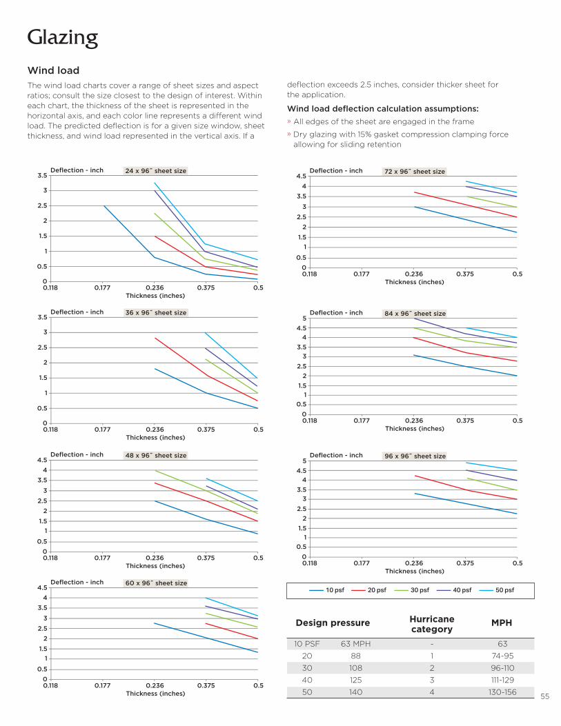
55
Glazing
deflection exceeds 2.5 inches, consider thicker sheet for the application.
Wind load deflection calculation assumptions:» All edges of the sheet are engaged in the frame
» Dry glazing with 15% gasket compression clamping force allowing for sliding retention
Wind loadThe wind load charts cover a range of sheet sizes and aspect ratios; consult the size closest to the design of interest. Within each chart, the thickness of the sheet is represented in the horizontal axis, and each color line represents a different wind load. The predicted deflection is for a given size window, sheet thickness, and wind load represented in the vertical axis. If a
24 x 96˝ sheet size
Thickness (inches)
Deflection - inch
0.118
3.5
2.5
1.5
0.5
0
3
2
1
0.177 0.236 0.375 0.5
36 x 96˝ sheet size
Thickness (inches)
Deflection - inch
0.118
3.5
2.5
1.5
0.5
0
3
2
1
0.177 0.236 0.375 0.5
48 x 96˝ sheet size
Thickness (inches)
Deflection - inch
0.118
2.5
1.5
0.50
3
3.54
4.5
2
1
0.177 0.236 0.375 0.5
60 x 96˝ sheet size
Thickness (inches)
Deflection - inch
0.118
2.5
1.5
0.50
3
3.54
4.5
2
1
0.177 0.236 0.375 0.5
72 x 96˝ sheet size
Thickness (inches)
Deflection - inch
0.118
2.5
1.5
0.50
3
3.54
4.5
2
1
0.177 0.236 0.375 0.5
96 x 96˝ sheet size
Thickness (inches)
Deflection - inch
0.118
2.5
1.5
0.50
33.5
44.5
5
2
1
0.177 0.236 0.375 0.5
84 x 96˝ sheet size
Thickness (inches)
Deflection - inch
0.118
2.5
1.5
0.50
33.5
44.5
5
2
1
0.177 0.236 0.375 0.5
Design pressure Hurricane MPH category 10 PSF 63 MPH - 63
20 88 1 74-95
30 108 2 96-110
40 125 3 111-129
50 140 4 130-156
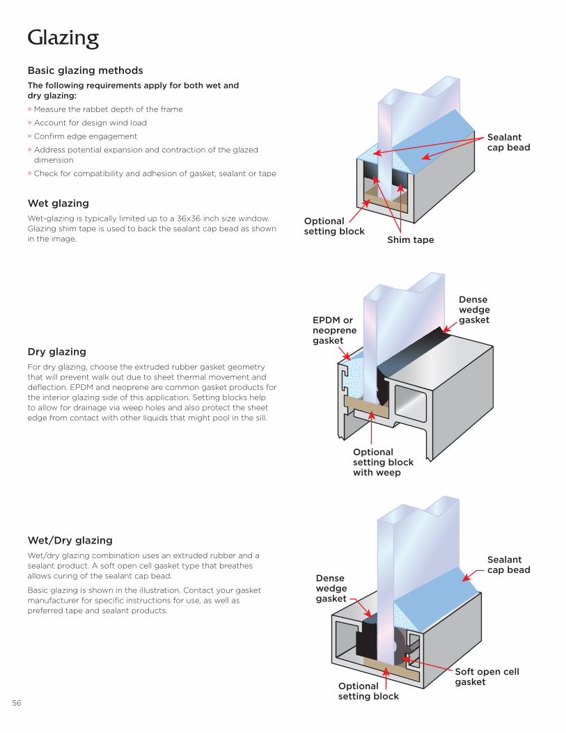
56
GlazingBasic glazing methodsThe following requirements apply for both wet and dry glazing:» Measure the rabbet depth of the frame
» Account for design wind load
» Confirm edge engagement
» Address potential expansion and contraction of the glazed dimension
» Check for compatibility and adhesion of gasket, sealant or tape
Wet glazingWet-glazing is typically limited up to a 36x36 inch size window. Glazing shim tape is used to back the sealant cap bead as shown in the image.
Dry glazingFor dry glazing, choose the extruded rubber gasket geometry that will prevent walk out due to sheet thermal movement and deflection. EPDM and neoprene are common gasket products for the interior glazing side of this application. Setting blocks help to allow for drainage via weep holes and also protect the sheet edge from contact with other liquids that might pool in the sill.
Wet/Dry glazingWet/dry glazing combination uses an extruded rubber and a sealant product. A soft open cell gasket type that breathes allows curing of the sealant cap bead.
Basic glazing is shown in the illustration. Contact your gasket manufacturer for specific instructions for use, as well as preferred tape and sealant products.
Sealantcap bead
Shim tape
Optionalsetting block
Densewedgegasket
Optionalsetting blockwith weep
EPDM orneoprenegasket
Densewedgegasket
Sealantcap bead
Soft open cellgasketOptional
setting block
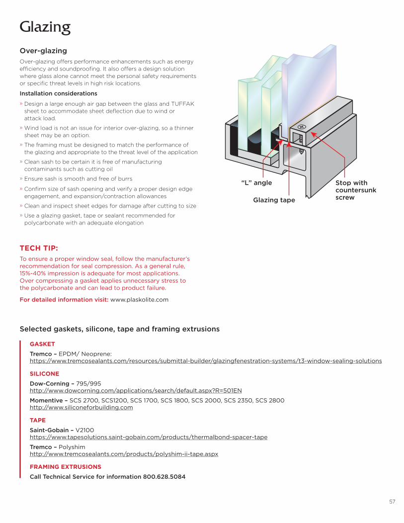
57
GlazingOver-glazingOver-glazing offers performance enhancements such as energy efficiency and soundproofing. It also offers a design solution where glass alone cannot meet the personal safety requirements or specific threat levels in high risk locations.
Installation considerations
» Design a large enough air gap between the glass and TUFFAK sheet to accommodate sheet deflection due to wind or attack load.
» Wind load is not an issue for interior over-glazing, so a thinner sheet may be an option.
» The framing must be designed to match the performance of the glazing and appropriate to the threat level of the application
» Clean sash to be certain it is free of manufacturing contaminants such as cutting oil
» Ensure sash is smooth and free of burrs
» Confirm size of sash opening and verify a proper design edge engagement, and expansion/contraction allowances
» Clean and inspect sheet edges for damage after cutting to size
» Use a glazing gasket, tape or sealant recommended for polycarbonate with an adequate elongation
“L” angle
Glazing tape
Stop withcountersunkscrew
Selected gaskets, silicone, tape and framing extrusions
GASKET
Tremco – EPDM/ Neoprene: https://www.tremcosealants.com/resources/submittal-builder/glazingfenestration-systems/t3-window-sealing-solutions
SILICONE
Dow-Corning – 795/995 http://www.dowcorning.com/applications/search/default.aspx?R=501EN
Momentive – SCS 2700, SCS1200, SCS 1700, SCS 1800, SCS 2000, SCS 2350, SCS 2800 http://www.siliconeforbuilding.com
TAPE
Saint-Gobain – V2100 https://www.tapesolutions.saint-gobain.com/products/thermalbond-spacer-tape
Tremco – Polyshim http://www.tremcosealants.com/products/polyshim-ii-tape.aspx
FRAMING EXTRUSIONS
Call Technical Service for information 800.628.5084
TECH TIP:To ensure a proper window seal, follow the manufacturer’s recommendation for seal compression. As a general rule, 15%-40% impression is adequate for most applications. Over compressing a gasket applies unnecessary stress to the polycarbonate and can lead to product failure.
For detailed information visit: www.plaskolite.com
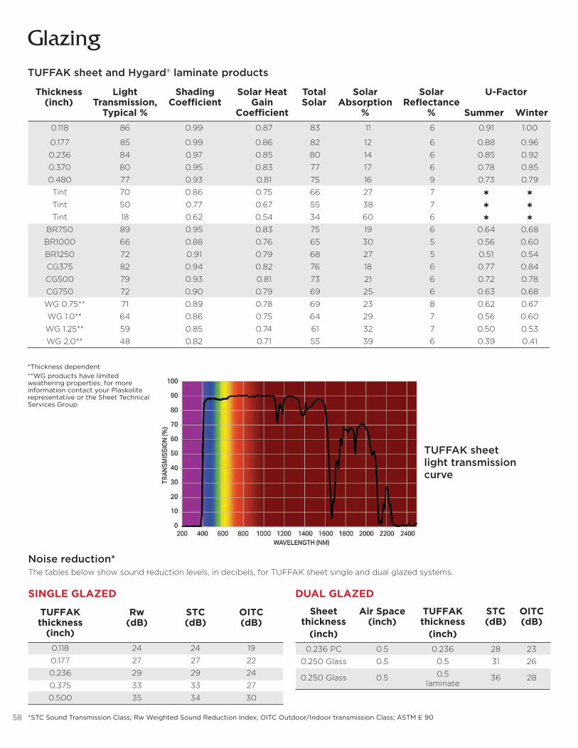
58
GlazingTUFFAK sheet and Hygard® laminate products
*Thickness dependent **WG products have limited weathering properties, for more information contact your Plaskolite representative or the Sheet Technical Services Group
Thickness Light Shading Solar Heat Total Solar Solar U-Factor (inch) Transmission, Coefficient Gain Solar Absorption Reflectance Typical % Coefficient % % Summer Winter 0.118 86 0.99 0.87 83 11 6 0.91 1.00
0.177 85 0.99 0.86 82 12 6 0.88 0.96
0.236 84 0.97 0.85 80 14 6 0.85 0.92
0.370 80 0.95 0.83 77 17 6 0.78 0.85
0.480 77 0.93 0.81 75 16 9 0.73 0.79
Tint 70 0.86 0.75 66 27 7 Q Q
Tint 50 0.77 0.67 55 38 7 Q Q
Tint 18 0.62 0.54 34 60 6 Q Q
BR750 89 0.95 0.83 75 19 6 0.64 0.68
BR1000 66 0.88 0.76 65 30 5 0.56 0.60
BR1250 72 0.91 0.79 68 27 5 0.51 0.54
CG375 82 0.94 0.82 76 18 6 0.77 0.84
CG500 79 0.93 0.81 73 21 6 0.72 0.78
CG750 72 0.90 0.79 69 25 6 0.63 0.68
WG 0.75** 71 0.89 0.78 69 23 8 0.62 0.67
WG 1.0** 64 0.86 0.75 64 29 7 0.56 0.60
WG 1.25** 59 0.85 0.74 61 32 7 0.50 0.53
WG 2.0** 48 0.82 0.71 55 39 6 0.39 0.41
Noise reduction*The tables below show sound reduction levels, in decibels, for TUFFAK sheet single and dual glazed systems.
DUAL GLAZEDSINGLE GLAZED
TUFFAK Rw STC OITC thickness (dB) (dB) (dB) (inch) 0.118 24 24 19
0.177 27 27 22
0.236 29 29 24
0.375 33 33 27
0.500 35 34 30
Sheet Air Space TUFFAK STC OITC thickness (inch) thickness (dB) (dB) (inch) (inch) 0.236 PC 0.5 0.236 28 23
0.250 Glass 0.5 0.5 31 26
0.250 Glass 0.5 0.5 36 28 laminate
TUFFAK sheet light transmission curve
*STC Sound Transmission Class; Rw Weighted Sound Reduction Index; OITC Outdoor/Indoor transmission Class; ASTM E 90


© 2019 PLASKOLITE, LLC 082019 TUFFAK® and Hygard® are registered trademarks of Plaskolite LLC Bayblend® is a registered trademark of Covestro AG
PLASKOLITE
400 Nationwide Blvd, Suite 400 Columbus, OH 43215800.848.9124 • Fax: [email protected]
These suggestions and data are based on information we believe to be reliable. They are offered in good faith, but without guarantee, as conditions and methods of use are beyond our control. We recommend that the prospective user determine the suitability of our materials and suggestions before adopting them on a commercial scale.
BRO002