TUBULAR CENTRIFUGAL INLINE FANS T Fa n - tcf.com · 3 The TSL Tubular Centrifugal Fan employs a...
20
CATALOG 1001 | APRIL 2014 WWW.TCF.COM INDUSTRIAL PROCESS AND COMMERCIAL VENTILATION SYSTEMS Twin City Fan TUBULAR CENTRIFUGAL INLINE FANS MODEL TSL
Transcript of TUBULAR CENTRIFUGAL INLINE FANS T Fa n - tcf.com · 3 The TSL Tubular Centrifugal Fan employs a...

CATALOG 1001 | APRIL 2014 WWW.TCF.COM
INDUSTRIAL PROCESS AND
COMMERCIAL VENTILATION SYSTEMS
Twin City Fan
Twin City FanTUBULAR CENTRIFUGALINLINE FANSMODEL TSL

TWIN CITY FAN - CATALOG 10012
The TSL is an inline centrifugal flow fan featuring the reli-able performance of a centrifugal fan with the space sav-ing advantages of an axial type fan. The TSL offers high efficiencies in the commonly selected area. The TSL has a higher and broader efficiency range compared to competi-tive tubular fans and square inline fans. Lower operating speed for a given performance provides longer and more reliable operation. Also, higher efficiency leads to quieter operation. The unique wheel design allows air to flow with a minimum of turbulence and losses. Extra-wide blade design delivers a larger air volume. A removable discharge cone facilitates maintenance and service. Applications with larger motors utilize a pivot-style motor base for ease of belt tension adjustments.
Standard Specifications• High efficient open back plate airfoil wheel, sizes 182
through 890 (patent #5,171,128)• Average bearing life (AFBMA L-50) exceeds 200,000
hours at maximum class RPM• Shaft diameters sized so that maximum operating speed
does not exceed 70% of first critical speed• Wheels are statically and dynamically balanced prior
to assembly. Fans with motors and drives mounted by Twin City Fan are test run as a complete assembly and rechecked for balance at the specified operating speed.
Capabilities & Features• Sizes 12.25" and 15" diameter with flat-blade backward
inclined wheel• Sizes 18.25" through 89" diameter with patented open
back plate airfoil wheel• Class I, II, and III construction• Arrangements 1, 4 and 9• Horizontal and vertical mounting arrangements• Airflow to 221,700 CFM• Static pressures to 9" w.g
Twin City Fan & Blower certifies that the Model TSL fans shown herein are licensed to bear the AMCA Seal. The ratings shown are based on tests and procedures performed in accordance with AMCA Publication 211 and AMCA Publication 311 and comply with the requirements of the AMCA Certified Ratings Program. See Catalog 1002 for sound ratings.
Model TSL Arr. 9
Model TSL
Model TSL is available with the UL/cUL 705 listing for electrical, File No. E158680.
Twin City Fan
Twin City Fan
CENTRIFUGAL INLINE FANS

WWW.TCF.COM 3
The TSL Tubular Centrifugal Fan employs a specially designed non-overloading airfoil wheel. In a tubular centrifugal fan, the air turns 90° after leaving the wheel. Twin City Fan & Blower’s unique wheel design with open back plate (patent #5,171,128) allows this turn to be made with a minimum of turbulence and loss. Also, the extra-wide blade design helps deliver a larger air volume for a given wheel diameter. The TSL wheel improves overall efficiency and reduces overall sound levels.
Performance Comparison — 361⁄2" Wheel Diameter Tubular Centrifugal Fans
Competition’s Design: Turbulent airflow causes loss of efficiency.
Model TSL by Twin City Fan & Blower: Streamlined airflow makes use of the open backplate wheel design.
100
80
60
40
20
100
80
60
40
20
0 20 40 60 80 100VOLUME - IN % OF WIDE OPEN VOLUME (WOV)
STA
TIC P
RESSURE IN %
OF
SHUTO
FF N
O D
ELIVERY (SND)
BRAKE P
OWER IN %
OF
MAX. POWER
TOTALEFFICIENCY
POWER
SP
TYPICALSELECTION
REGION
Typical Non-overloading Characteristic Curve For Model TSL Tubular Centrifugal Fans
ALL PERFORMANCE COMPARISONS ARE BASED ON MANUFACTURERS’ PUBLISHED DATA.
TSL Wheel
PERFORMANCETWIN CITY FAN
TUBULAR CENTRIF.MANUFACTURER ATUBULAR CENTRIF.
MANUFACTURER BTUBULAR CENTRIF.
MANUFACTURER CTUBULAR CENTRIF.
MANUFACTURER DTUBULAR CENTRIF.
CFM SP RPM BHP RPM BHP RPM BHP RPM BHP RPM BHP17330 1.5" 774 6.5 799 7.3 876 7.7 840 7.7 775 9.414660 1" 646 3.8 670 4.3 734 4.5 670 5.8 640 5.510660 2" 686 4.6 698 4.8 715 4.6 790 8.1 775 7.219990 3" 977 13.6 1004 14.9 1080 15.2 1062 16.1 N/A N/A33500 7" 1562 55.0 1610 60.4 1750 63.1 1700 65.0 N/A N/A31990 0.75" 1175 18.4 1234 22.8 1370 24.0 1230 18.7 N/A N/A
WHEEL DESIGN
TWIN CITY FAN - CATALOG 10014
Tubular centrifugal fans such as the TSL are used pri-marily for low to medium pressure return air systems in heating, ventilating, and air conditioning applications. They are generally more compact than comparable scroll type centrifugal fans and often will fit into tight spaces or in overhead ductwork where other fans of the same duty may not. This is particularly true of the TSL inline fans, which were specifically engineered with a wider efficiency range. This allows selection of smaller fans while main-taining high efficiencies and low operating costs.
While there are many considerations that must be taken into account when selecting a fan for a particular appli-cation, the first and most obvious is the operating char-acteristic of the fan. The fan selected must be capable of moving the required amount of air against the cal-culated system static pressure. Fans selected at or just below the maximum static efficiency point (underlined figures in the performance tables) will provide the most efficient and quietest operation. This, however, does not necessarily mean that a fan selected at this point is the best fan for the job. The most efficient fan is usually the largest fan that can be chosen to provide stable opera-tion for a given performance. Usually there is a trade-off between higher equipment cost vs. lower operating cost.
There are also many site specific considerations such as physical size and quiet operation which must be evalu-ated before a final selection is made.
This is one area where the unique features of the TSL fan can provide a real advantage over other inline fans. A smaller TSL fan operating further down from the maximum efficiency figures may be selected without sig-nificantly increasing the horsepower requirements, RPM, or sound power levels. This means you have less of a compromise to make between size and cost vs. operat-ing cost and quiet operation. With the TSL fan, you can have both high efficiency and lower first cost.
All of the features that give the standard TSL its high efficiency are utilized on all styles and arrangements that Twin City Fan & Blower offers. When supplied with a curb cap, discharge cap, and weather cover, the TSL fan becomes a quiet, efficient, and stable upblast style roof exhauster. TSL fans can also be specified for many industrial applications, such as paint spray booths. These installations typically utilize special features such as clamshell or swingout construction, which allow easy access for cleaning and maintenance.
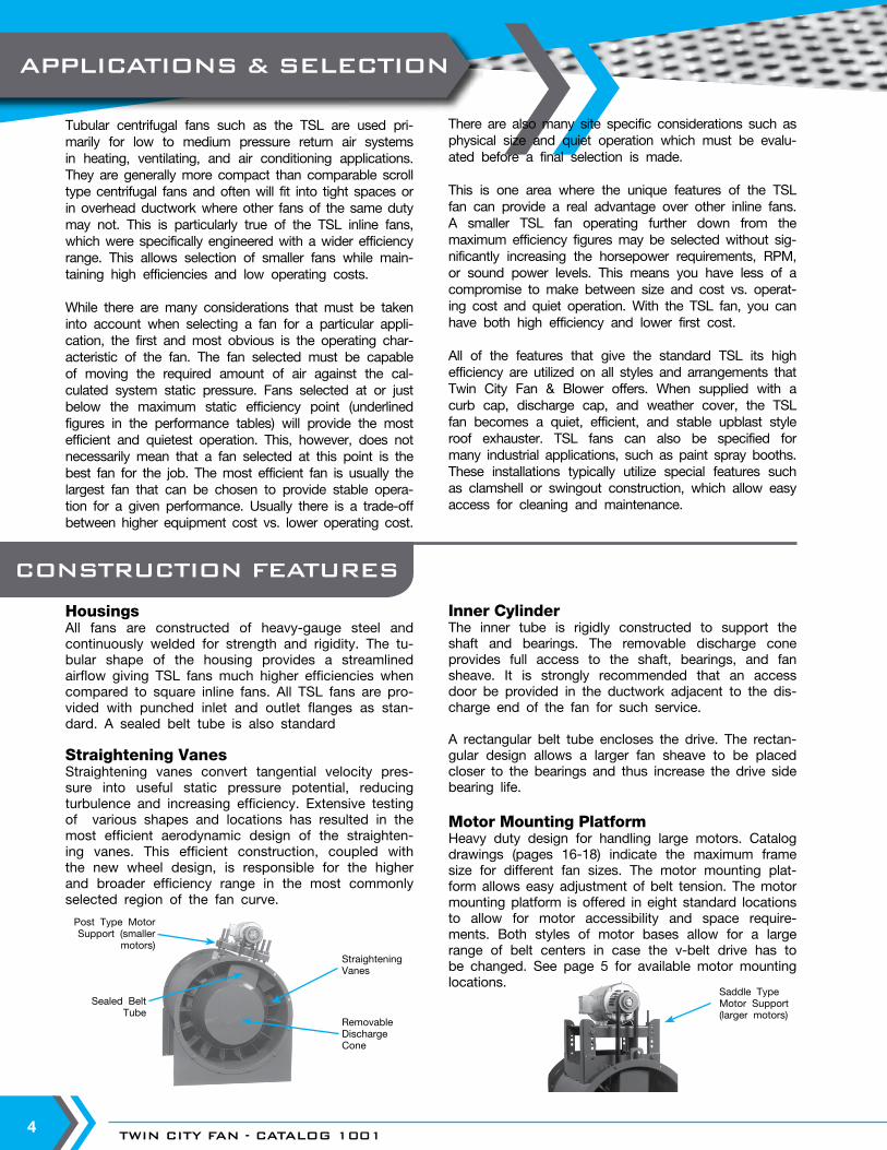
HousingsAll fans are constructed of heavy-gauge steel and continuously welded for strength and rigidity. The tu-bular shape of the housing provides a streamlined airflow giving TSL fans much higher efficiencies when compared to square inline fans. All TSL fans are pro-vided with punched inlet and outlet flanges as stan-dard. A sealed belt tube is also standard
Straightening VanesStraightening vanes convert tangential velocity pres-sure into useful static pressure potential, reducing turbulence and increasing efficiency. Extensive testing of various shapes and locations has resulted in the most efficient aerodynamic design of the straighten-ing vanes. This efficient construction, coupled with the new wheel design, is responsible for the higher and broader efficiency range in the most commonly selected region of the fan curve.
Post Type MotorSupport (smaller
motors)
Sealed Belt Tube
Straightening Vanes
Removable Discharge Cone
Saddle Type Motor Support (larger motors)
Inner CylinderThe inner tube is rigidly constructed to support the shaft and bearings. The removable discharge cone provides full access to the shaft, bearings, and fan sheave. It is strongly recommended that an access door be provided in the ductwork adjacent to the dis-charge end of the fan for such service.
A rectangular belt tube encloses the drive. The rectan-gular design allows a larger fan sheave to be placed closer to the bearings and thus increase the drive side bearing life.
Motor Mounting PlatformHeavy duty design for handling large motors. Catalog drawings (pages 16-18) indicate the maximum frame size for different fan sizes. The motor mounting plat-form allows easy adjustment of belt tension. The motor mounting platform is offered in eight standard locations to allow for motor accessibility and space require-ments. Both styles of motor bases allow for a large range of belt centers in case the v-belt drive has to be changed. See page 5 for available motor mounting locations.
CONSTRUCTION FEATURES
APPLICATIONS & SELECTION

WWW.TCF.COM 5
Model TSL fans are available for horizontal and verti-cal mounting. Built in sizes 122 through 890, and in several styles as illustrated below, a wide variety of operating requirements are easily handled.
Arrangement 9 is widely used for tubular fans. In Ar-rangement 9, the motor is supported by a motor plat-form welded directly to the fan housing. Arrangement 1 is also available.
Horizontal ConstructionHorizontal Base Mounted (HBM) — Support legs are provided at each end of the fan for floor mounting.
Horizontal Ceiling Hung (HCH) — For duct mounted fans, four suspension clips are welded to the fan casing to allow ceiling suspension using rod hangers.
Vertical ConstructionVertical construction is available in sizes 122 through 542. Consult factory for larger sizes.
Floor or Ceiling Mounted — Four vertical brackets are welded to either end of the fan housing. Bracket location is determined by airflow direction and support details (see drawing below).
Roof Mounted — A curb cap provides weathertight seal for roof curb mounted fans. A discharge cap and weather cover are also available for the upblast style roof ventilator.
Motor Positions
AB
C
DE
F
G
HA
B
CG
HHBM
Viewed FromOutlet End
HCHViewed From
Outlet End
Discharge Designations for Vertical Flow Options
AIRFLOW
↓AIRFLOW
↓↑
AIRFLOW
↑AIRFLOW
↑AIRFLOW
VRM VUN VUI VUO VDI VDO VDN Vertical Roof Vertical Up Discharge Up Discharge Up Discharge Down Discharge Down Vertical Down Mount No Brackets Floor Mount Ceiling Hung Ceiling Hung Floor Mount No Brackets (Usually Curb Support Brackets Support Brackets Support Brackets Support Brackets Mounted) On Inlet On Outlet On Inlet On Outlet
MOUNTING ARRANGEMENTS
VRM – Vertical Roof Mount
HBM – Horizontal Base Mount
AIRFLOW
↓
↑AIRFLOW
STANDARD CONSTRUCTION

TWIN CITY FAN - CATALOG 10016
Clamshell DesignTwo clamshell style doors swing open to provide complete ac-cess to the interior of the fan for maintenance or cleaning without removal of ductwork. Heavy duty hinges, positive locking latches, and full gasketing provide a complete seal when doors are closed. An access door provides access to the bearings. Available on all fan sizes, typically vertical mount due to the weight of the doors.
Swingout DesignProvides full access to the wheel and inner casing. The entire wheel/shaft/bearing assembly is mounted on a large swingout door. Since the inlet cone pivots with the door, fan performance is preserved. Ideal for systems requiring frequent cleaning without removal of ductwork. Swingout construction is available for vertical mounting only. Available on sizes 182 and larger.
Fumehood Exhaust DesignTwin City Fan & Blower offers a specially modified version of the TSL fan designated as “TFE” (Tubular Fume Exhaust) for laboratory fume hood exhaust applications, available in sizes 90 through 542. The TFE fan consists of a vertically mounted TSL unit with a rein-forced curb cap and a modified discharge cap. The discharge cap includes an outlet venturi to permit the outlet velocity to meet the specific roof exhaust requirements. TFE fans in a standard configu-ration utilize an extended discharge with optional stack extensions available. The heavy duty curb cap will permit stack extensions up to 10 feet (120 inches) total height from the roof line without need for guide wires.
Refer to Catalog 1500 for selection and specifications.
Clamshell Design
Swingout Design
Venturi DischargeCap Assembly
with Nozzle
Optional StackExtension
WeatherCover
OptionalBypass Damper
Removable Access Panel
Model TSL Fanwith Extended
Housing
Optional Isolation DamperMixing Box
Optional Roof Curb
OPTIONAL DESIGNS
WWW.TCF.COM 7
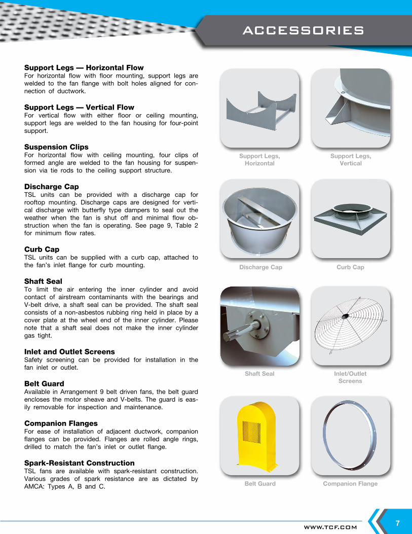
Support Legs — Horizontal FlowFor horizontal flow with floor mounting, support legs are welded to the fan flange with bolt holes aligned for con-nection of ductwork.
Support Legs — Vertical FlowFor vertical flow with either floor or ceiling mounting, support legs are welded to the fan housing for four-point support.
Suspension ClipsFor horizontal flow with ceiling mounting, four clips of formed angle are welded to the fan housing for suspen-sion via tie rods to the ceiling support structure.
Discharge CapTSL units can be provided with a discharge cap for rooftop mounting. Discharge caps are designed for verti-cal discharge with butterfly type dampers to seal out the weather when the fan is shut off and minimal flow ob-struction when the fan is operating. See page 9, Table 2 for minimum flow rates.
Curb CapTSL units can be supplied with a curb cap, attached to the fan’s inlet flange for curb mounting.
Shaft SealTo limit the air entering the inner cylinder and avoid contact of airstream contaminants with the bearings and V-belt drive, a shaft seal can be provided. The shaft seal consists of a non-asbestos rubbing ring held in place by a cover plate at the wheel end of the inner cylinder. Please note that a shaft seal does not make the inner cylinder gas tight.
Inlet and Outlet ScreensSafety screening can be provided for installation in the fan inlet or outlet.
Belt Guard Available in Arrangement 9 belt driven fans, the belt guard encloses the motor sheave and V-belts. The guard is eas-ily removable for inspection and maintenance.
Companion FlangesFor ease of installation of adjacent ductwork, companion flanges can be provided. Flanges are rolled angle rings, drilled to match the fan’s inlet or outlet flange.
Spark-Resistant ConstructionTSL fans are available with spark-resistant construction. Various grades of spark resistance are as dictated by AMCA: Types A, B and C.
Discharge Cap Curb Cap
Support Legs,Vertical
Inlet/OutletScreens
Companion Flange
Support Legs,Horizontal
Shaft Seal
Belt Guard
ACCESSORIES

TWIN CITY FAN - CATALOG 10018
Vibration IsolationTSL fans can be provided with spring or rubber-in-shear isolators as an option. Spring isolators can be provided for floor mount or ceiling hung orientation.
Weather CoverFor outdoor installations, the weather cover completely encloses the motor and V-belt drive from the elements. Provided with slots for ventilation, the cover is easily removable for inspection and maintenance. Weather covers are available for either horizontal or vertical flow fans.
Inlet VanesVariable inlet vanes provide economical, stable, and efficient air volume control for manual or motorized operation.
Variable inlet vanes are widely used to control air volumes at partial load conditions, resulting in substantial savings in energy. Inlet vane control offers wide range regulation, excellent operating cost savings, simplicity in operation, and long trouble-free operation at a relatively low initial cost.
Variable inlet vanes cause the air entering the fan to spin in the direction of wheel rotation, resulting in reduction in capacity, pressure, and brake horsepower. With the use of inlet vanes, the fan performance curve is repositioned from fully open to the closed position of inlet vanes as shown below.
Low maintenance, easy assembly, disassembly, and long life are prime features of this vane design. Blades are supported with fatigue resistant steel shafts and two needle roller bearings riding on a zone hardened surface to minimize the wear. Bearings are lubricated for life with high grade moisture-resistant grease and protected with special seals. The vane bearing housings are welded in position and stiffened with a welded-on support ring. The welded structure eliminates flutter and vibration while utilizing a cantilevered design.
100
80
60
40
20
% O
F DESIG
N P
OWER
0 20 40 60 80 100% OF DESIGN VOLUME
10
8
6
4
2
200
160
120
80
40
0 2 4 6 8 10
STA
TIC P
RESSURE (IN W
.G.)
BRAKEPOWER (BHP)
VOLUME (CFM) x 10,000
SP @ VANE SETTING
75
75
50
50
25
25
0
0
100
100
SYSTEM CURVE
BHP @ VANESETTING
Performance Curve at Energy Savings Different Vane Settings Using Inlet Vanes
Variable Inlet Vanes
Weather CoverVibration Isolation
ACCESSORIES

WWW.TCF.COM 9
Table 1. Maximum RPM, Wheel Weights, and WR2 (moment of inertia in lb-ft2)
Table 3. Bare Fan Weights (lb)
Table 2. Minimum Volume Required to Open Discharge Cap
MAXIMUM RPM: Class I — 3583 Class II — 4000Legend: Performance shown is for installation Type B: Free inlet, ducted outlet.Class I = Regular face to left of Class II Power rating (BHP) does not include transmission losses.Class II = Regular face in light shaded area Performance ratings do not include the effects of appurtenances (accessories).Class III = Bold face to right of Class II Underlined figures indicate maximum static efficiency.
PERFORMANCE DATA
FANSIZE
CLASS I CLASS II CLASS IIIMAX.RPM
WEIGHTLB
WR2
LB-FT2MAX.RPM
WEIGHTLB
WR2
LB-FT2MAX.RPM
WEIGHTLB
WR2
LB-FT2
122 3583 14 1.8 4676 19 2.6 — — —150 2927 20 4.3 3819 26 5.8 — — —182 2237 32 9.3 2917 36 10 3689 57 15200 2042 38 13 2662 41 14 3367 64 20222 1835 62 23 2393 62 23 3026 92 35245 1667 74 35 2173 74 35 2748 105 49270 1486 86 51 1938 86 51 2441 121 71300 1338 101 77 1745 119 95 2197 141 107330 1216 123 114 1586 144 134 1998 183 179365 1081 157 185 1410 181 216 1776 243 293402 981 194 273 1279 216 321 1611 278 404445 887 274 430 1157 328 563 1457 405 672490 806 317 622 1051 384 822 1323 468 968542 728 411 1060 949 480 1237 1195 576 1506600 658 524 1705 858 573 1854 1081 680 2212660 598 748 2573 780 807 2888 983 965 3576730 541 944 4230 705 944 4250 888 1121 5039807 489 1151 6595 638 1217 7080 833 1356 8032890 444 1841 12706 579 1843 12606 729 1920 13674
SIZE CFM122 1051150 1707182 2532200 3527222 3527245 4693270 6574300 7605330 8712365 11158402 15891445 15891490 20904542 26613
FANSIZE
ARRANGEMENT I ARRANGEMENT 9
CLASS I CLASS II CLASS III CLASS I CLASS II CLASS III
122 — — — 220 240 —150 — — — 240 260 —182 355 391 430 273 300 330200 396 436 479 330 363 379222 460 506 556 360 396 435245 540 594 653 405 446 490270 680 748 822 490 539 598300 1050 1155 1270 780 838 943330 1450 1595 1754 1010 1111 1222365 1600 1760 1936 1250 1375 1512402 1990 2189 2407 1400 1540 1694445 2465 2712 2983 1900 2090 2299490 3000 3300 3630 2400 2640 2904542 3700 4070 4477 3200 3520 3872600 5200 5720 6292 4300 4730 5203660 6500 7150 7865 5850 6435 7078730 9000 9900 10890 7800 8580 9438807 11000 12100 13810 9900 10890 11979890 14500 15950 17545 13000 14300 15730
CFM OV0.5" SP 1" SP 1.5" SP 2" SP 3" SP 4" SP 5" SP 6" SP 7" SP 8" SP 9" SP
RPM BHP RPM BHP RPM BHP RPM BHP RPM BHP RPM BHP RPM BHP RPM BHP RPM BHP RPM BHP RPM BHP755 500 1193 0.12 1483 0.23906 600 1321 0.17 1568 0.281057 700 1456 0.22 1679 0.35 1885 0.49 2093 0.641208 800 1596 0.28 1804 0.43 1991 0.58 2169 0.741359 900 1743 0.37 1937 0.52 2108 0.69 2272 0.86 2589 1.241510 1000 1896 0.46 2073 0.63 2236 0.81 2386 1.00 2676 1.39 2965 1.841661 1100 2053 0.58 2212 0.76 2370 0.96 2511 1.16 2781 1.57 3039 2.021812 1200 2213 0.73 2357 0.91 2505 1.12 2642 1.34 2893 1.78 3136 2.25 3372 2.752114 1400 2537 1.08 2660 1.28 2785 1.51 2912 1.76 3144 2.26 3358 2.78 3568 3.32 3771 3.88 3974 4.492416 1600 2867 1.55 2974 1.77 3081 2.01 3192 2.28 3411 2.85 3609 3.42 3796 4.01 3981 4.622718 1800 3200 2.14 3295 2.39 3390 2.65 3486 2.92 3684 3.54 3875 4.203020 2000 3536 2.88 3621 3.15 3707 3.43 3792 3.72 3968 4.363322 2200 3874 3.78 3951 4.063624 24003926 26004228 2800
122 TSL Wheel Type: Flat Blade BI Inlet & Outlet Area: 1.51 ft2 Fan Efficiency Grade = FEG63Wheel Dia.: 12.25" Tip Speed FPM = 3.21 x RPM Inlet & Outlet Dia.: 16.56" Max. BHP = 0.073 (RPM÷1000)3
ENGINEERING DATA

TWIN CITY FAN - CATALOG 100110
MAXIMUM RPM: Class I — 2927 Class II — 3819
MAXIMUM RPM: Class I — 2237 Class II — 2917 Class III — 3689
MAXIMUM RPM: Class I — 2042 Class II — 2662 Class III — 3367
Legend: Performance shown is for installation Type B: Free inlet, ducted outlet.Class I = Regular face to left of Class II Power rating (BHP) does not include transmission losses.Class II = Regular face in light shaded area Performance ratings do not include the effects of appurtenances (accessories).Class III = Bold face to right of Class II Underlined figures indicate maximum static efficiency.
CFM OV0.5" SP 1" SP 1.5" SP 2" SP 3" SP 4" SP 5" SP 6" SP 7" SP 8" SP 9" SP
RPM BHP RPM BHP RPM BHP RPM BHP RPM BHP RPM BHP RPM BHP RPM BHP RPM BHP RPM BHP RPM BHP1125 500 971 0.18 1209 0.341350 600 1075 0.25 1277 0.421575 700 1184 0.33 1367 0.52 1536 0.721800 800 1298 0.42 1468 0.63 1621 0.86 1768 1.102025 900 1417 0.54 1576 0.78 1716 1.02 1851 1.28 2111 1.842250 1000 1541 0.69 1686 0.94 1820 1.21 1943 1.48 2181 2.07 2419 2.742475 1100 1668 0.86 1799 1.13 1928 1.42 2044 1.72 2265 2.34 2477 3.012700 1200 1797 1.07 1916 1.35 2038 1.67 2150 1.98 2356 2.64 2555 3.34 2749 4.103150 1400 2061 1.60 2161 1.90 2264 2.24 2369 2.61 2558 3.36 2734 4.12 2906 4.93 3073 5.78 3240 6.693600 1600 2328 2.29 2416 2.62 2504 2.98 2595 3.37 2775 4.23 2937 5.08 3090 5.95 3242 6.87 3390 7.81 3535 8.79 3682 9.834050 1800 2598 3.16 2676 3.52 2754 3.91 2833 4.32 2996 5.25 3152 6.22 3295 7.17 3432 8.15 3568 9.17 3702 10.214500 2000 2871 4.24 2941 4.64 3011 5.06 3081 5.49 3226 6.46 3372 7.52 3510 8.59 3639 9.65 3763 10.734950 2200 3145 5.56 3208 5.99 3272 6.44 3336 6.91 3465 7.91 3598 9.02 3730 10.205400 2400 3419 7.13 3478 7.60 3536 8.08 3594 8.57 3712 9.635850 2600 3695 8.98 3749 9.48 3802 9.996300 2800
CFM OV0.5" SP 1" SP 1.5" SP 2" SP 3" SP 4" SP 5" SP 6" SP 7" SP 8" SP 9" SP
RPM BHP RPM BHP RPM BHP RPM BHP RPM BHP RPM BHP RPM BHP RPM BHP RPM BHP RPM BHP RPM BHP1670 500 766 0.21 975 0.412004 600 834 0.26 1022 0.492338 700 909 0.33 1079 0.58 1233 0.852672 800 990 0.42 1145 0.69 1287 0.98 1420 1.303006 900 1076 0.52 1216 0.81 1349 1.13 1473 1.47 1702 2.213340 1000 1164 0.64 1293 0.96 1416 1.30 1532 1.66 1749 2.43 1949 3.283674 1100 1255 0.79 1374 1.12 1488 1.49 1597 1.87 1802 2.69 1993 3.584008 1200 1348 0.96 1458 1.31 1564 1.70 1667 2.11 1861 2.97 2044 3.90 2214 4.894676 1400 1538 1.39 1634 1.79 1727 2.21 1818 2.66 1993 3.62 2158 4.63 2316 5.70 2467 6.82 2610 7.995344 1600 1731 1.93 1816 2.38 1899 2.85 1980 3.34 2138 4.38 2289 5.49 2435 6.66 2574 7.85 2710 9.10 2840 10.40 2965 11.736012 1800 1927 2.63 2003 3.12 2078 3.63 2151 4.16 2294 5.29 2433 6.49 2567 7.74 2697 9.04 2823 10.37 2945 11.74 3065 13.166680 2000 2125 3.48 2194 4.02 2262 4.58 2329 5.16 2459 6.37 2586 7.64 2711 8.99 2832 10.38 2950 11.81 3064 13.26 3176 14.767348 2200 2324 4.51 2387 5.09 2449 5.70 2511 6.33 2631 7.62 2748 8.98 2863 10.40 2976 11.88 3087 13.41 3195 14.97 3300 16.568016 2400 2524 5.73 2582 6.37 2639 7.02 2696 7.69 2808 9.08 2917 10.53 3024 12.04 3129 13.59 3232 15.20 3334 16.85 3434 18.548684 2600 2725 7.17 2778 7.85 2832 8.56 2885 9.27 2988 10.74 3090 12.28 3190 13.88 3288 15.51 3385 17.20 3481 18.94 3576 20.739352 2800 2926 8.83 2976 9.56 3026 10.32 3075 11.08 3172 12.65 3268 14.28 3362 15.96 3454 17.68 3545 19.45 3635 21.27
CFM OV0.5" SP 1" SP 1.5" SP 2" SP 3" SP 4" SP 5" SP 6" SP 7" SP 8" SP 9" SP
RPM BHP RPM BHP RPM BHP RPM BHP RPM BHP RPM BHP RPM BHP RPM BHP RPM BHP RPM BHP RPM BHP2020 500 701 0.25 891 0.502424 600 763 0.32 934 0.592828 700 833 0.40 987 0.70 1128 1.033232 800 908 0.51 1048 0.83 1178 1.19 1298 1.573636 900 987 0.63 1114 0.98 1234 1.37 1347 1.78 1555 2.664040 1000 1068 0.78 1185 1.16 1297 1.57 1402 2.01 1600 2.95 1781 3.974444 1100 1152 0.96 1260 1.37 1363 1.80 1463 2.27 1649 3.26 1822 4.334848 1200 1237 1.17 1337 1.60 1434 2.07 1527 2.56 1703 3.60 1869 4.72 2024 5.915656 1400 1412 1.69 1499 2.17 1584 2.69 1666 3.23 1825 4.39 1975 5.61 2118 6.90 2256 8.26 2386 9.666464 1600 1590 2.37 1667 2.90 1742 3.47 1816 4.07 1959 5.32 2096 6.66 2228 8.06 2355 9.50 2478 11.01 2597 12.58 2711 14.187272 1800 1770 3.21 1839 3.81 1907 4.43 1973 5.07 2103 6.43 2229 7.88 2351 9.39 2469 10.96 2583 12.56 2694 14.21 2803 15.928080 2000 1952 4.26 2014 4.91 2076 5.58 2137 6.29 2255 7.75 2370 9.28 2483 10.90 2593 12.58 2700 14.31 2805 16.08 2906 17.878888 2200 2135 5.52 2192 6.23 2248 6.96 2304 7.71 2413 9.28 2520 10.93 2624 12.64 2726 14.42 2827 16.27 2925 18.15 3021 20.079696 2400 2319 7.02 2371 7.78 2423 8.57 2475 9.39 2576 11.06 2675 12.82 2772 14.63 2867 16.50 2961 18.45 3054 20.45 3144 22.4810504 2600 2503 8.78 2552 9.61 2600 10.45 2648 11.32 2743 13.12 2835 14.97 2925 16.88 3015 18.87 3102 20.89 3189 22.99 3275 25.1511312 2800 2689 10.83 2734 11.71 2779 12.62 2824 13.55 2912 15.45 2998 17.40 3083 19.42 3167 21.51 3250 23.66 3332 25.85
150 TSL Wheel Type: Flat Blade BI Inlet & Outlet Area: 2.25 ft2 Fan Efficiency Grade = FEG60Wheel Dia.: 15.00" Tip Speed FPM = 3.93 x RPM Inlet & Outlet Dia.: 20.25" Max. BHP = 0.202 (RPM÷1000)3
182 TSL Wheel Type: Airfoil Inlet & Outlet Area: 3.34 ft2 Fan Efficiency Grade = FEG71Wheel Dia.: 18.25" Tip Speed FPM = 4.78 x RPM Inlet & Outlet Dia.: 24.25" Max. BHP = 0.46 (RPM÷1000)3
200 TSL Wheel Type: Airfoil Inlet & Outlet Area: 4.04 ft2 Fan Efficiency Grade = FEG71Wheel Dia.: 20.00" Tip Speed FPM = 5.24 x RPM Inlet & Outlet Dia.: 27.13" Max. BHP = 0.73 (RPM÷1000)3
PERFORMANCE DATA

WWW.TCF.COM 11
MAXIMUM RPM: Class I — 1835 Class II — 2393 Class III — 3026
MAXIMUM RPM: Class I — 1667 Class II — 2173 Class III — 2748
MAXIMUM RPM: Class I — 1486 Class II — 1938 Class III — 2441
Legend: Performance shown is for installation Type B: Free inlet, ducted outlet.Class I = Regular face to left of Class II Power rating (BHP) does not include transmission losses.Class II = Regular face in light shaded area Performance ratings do not include the effects of appurtenances (accessories).Class III = Bold face to right of Class II Underlined figures indicate maximum static efficiency.
CFM OV0.5" SP 1" SP 1.5" SP 2" SP 3" SP 4" SP 5" SP 6" SP 7" SP 8" SP 9" SP
RPM BHP RPM BHP RPM BHP RPM BHP RPM BHP RPM BHP RPM BHP RPM BHP RPM BHP RPM BHP RPM BHP2485 500 629 0.31 800 0.612982 600 684 0.39 838 0.723479 700 746 0.50 885 0.86 1012 1.273976 800 813 0.62 939 1.02 1056 1.46 1165 1.934473 900 883 0.78 998 1.21 1107 1.68 1208 2.18 1396 3.284970 1000 956 0.96 1061 1.42 1162 1.93 1257 2.47 1435 3.62 1599 4.895467 1100 1031 1.18 1128 1.67 1221 2.21 1311 2.79 1479 4.00 1635 5.325964 1200 1107 1.43 1197 1.96 1284 2.53 1368 3.14 1527 4.42 1677 5.81 1816 7.276958 1400 1262 2.06 1341 2.66 1418 3.29 1492 3.96 1635 5.39 1771 6.90 1900 8.48 2024 10.15 2141 11.887952 1600 1421 2.88 1491 3.55 1559 4.24 1625 4.97 1754 6.52 1879 8.18 1998 9.90 2112 11.68 2224 13.56 2330 15.47 2433 17.458946 1800 1582 3.91 1645 4.65 1706 5.41 1766 6.21 1883 7.88 1997 9.67 2107 11.53 2213 13.45 2316 15.42 2417 17.48 2515 19.599940 2000 1744 5.18 1801 5.98 1857 6.82 1912 7.68 2019 9.49 2123 11.39 2225 13.38 2324 15.45 2421 17.58 2515 19.75 2606 21.9610934 2200 1908 6.72 1960 7.60 2011 8.50 2061 9.42 2160 11.36 2256 13.39 2350 15.49 2443 17.70 2533 19.96 2622 22.29 2708 24.6411928 2400 2072 8.54 2120 9.49 2167 10.46 2213 11.45 2305 13.53 2394 15.68 2482 17.92 2568 20.24 2653 22.63 2736 25.08 2818 27.6012922 2600 2237 10.68 2281 11.70 2325 12.75 2368 13.81 2453 16.01 2537 18.31 2619 20.68 2699 23.10 2779 25.63 2857 28.20 2934 30.8413916 2800 2403 13.17 2444 14.27 2484 15.37 2525 16.52 2604 18.85 2683 21.28 2760 23.78 2835 26.33 2910 28.98 2984 31.68
CFM OV0.5" SP 1" SP 1.5" SP 2" SP 3" SP 4" SP 5" SP 6" SP 7" SP 8" SP 9" SP
RPM BHP RPM BHP RPM BHP RPM BHP RPM BHP RPM BHP RPM BHP RPM BHP RPM BHP RPM BHP RPM BHP3005 500 570 0.37 726 0.743606 600 620 0.47 761 0.884207 700 676 0.60 803 1.04 918 1.534808 800 737 0.75 852 1.24 958 1.76 1057 2.345409 900 800 0.93 905 1.46 1004 2.03 1096 2.64 1267 3.976010 1000 866 1.16 962 1.72 1054 2.33 1141 2.99 1303 4.39 1452 5.926611 1100 934 1.42 1023 2.02 1107 2.67 1189 3.37 1342 4.84 1484 6.447212 1200 1003 1.73 1085 2.36 1164 3.05 1241 3.79 1386 5.35 1522 7.03 1648 8.798414 1400 1144 2.49 1216 3.21 1285 3.97 1353 4.78 1483 6.51 1606 8.33 1724 10.25 1837 12.28 1944 14.389616 1600 1288 3.48 1351 4.27 1413 5.12 1474 6.01 1591 7.88 1704 9.88 1812 11.96 1916 14.11 2018 16.39 2115 18.72 2208 21.1110818 1800 1433 4.71 1490 5.60 1546 6.52 1601 7.49 1707 9.51 1811 11.67 1911 13.93 2008 16.26 2102 18.66 2193 21.13 2282 23.6812020 2000 1580 6.24 1632 7.21 1683 8.22 1733 9.27 1830 11.44 1925 13.75 2017 16.15 2108 18.67 2196 21.24 2281 23.86 2365 26.5613222 2200 1728 8.08 1775 9.14 1822 10.23 1868 11.36 1958 13.71 2045 16.15 2131 18.71 2215 21.37 2297 24.10 2378 26.92 2457 29.8014424 2400 1877 10.28 1921 11.43 1963 12.60 2006 13.81 2089 16.31 2170 18.91 2250 21.63 2328 24.42 2406 27.34 2482 30.32 2556 33.3515626 2600 2027 12.86 2067 14.10 2106 15.34 2146 16.65 2223 19.30 2299 22.07 2374 24.94 2447 27.89 2519 30.92 2591 34.07 2661 37.2616828 2800 2176 15.84 2214 17.18 2251 18.52 2288 19.91 2360 22.72 2431 25.64 2501 28.66 2570 31.77 2638 34.96 2705 38.23
CFM OV0.5" SP 1" SP 1.5" SP 2" SP 3" SP 4" SP 5" SP 6" SP 7" SP 8" SP 9" SP
RPM BHP RPM BHP RPM BHP RPM BHP RPM BHP RPM BHP RPM BHP RPM BHP RPM BHP RPM BHP RPM BHP3640 500 508 0.42 651 0.844368 600 552 0.53 677 0.995096 700 599 0.66 715 1.17 819 1.735824 800 652 0.83 758 1.38 853 1.98 943 2.646552 900 709 1.04 804 1.62 894 2.28 976 2.97 1134 4.487280 1000 767 1.28 852 1.89 938 2.60 1016 3.35 1161 4.94 1302 6.708008 1100 827 1.57 905 2.23 983 2.96 1059 3.77 1194 5.43 1324 7.258736 1200 888 1.91 960 2.61 1031 3.37 1103 4.22 1234 6.00 1355 7.90 1473 9.9210192 1400 1013 2.74 1077 3.56 1137 4.38 1198 5.28 1320 7.27 1430 9.33 1534 11.51 1637 13.82 1738 16.2311648 1600 1140 3.80 1197 4.74 1251 5.67 1304 6.62 1411 8.72 1517 11.04 1614 13.41 1706 15.86 1796 18.41 1885 21.05 1974 23.8313104 1800 1268 5.13 1320 6.19 1370 7.25 1417 8.28 1511 10.49 1607 12.94 1701 15.56 1788 18.20 1871 20.92 1951 23.70 2032 26.6414560 2000 1398 6.76 1445 7.93 1491 9.12 1535 10.29 1619 12.62 1704 15.15 1791 17.93 1876 20.84 1955 23.74 2031 26.73 2105 29.8016016 2200 1529 8.74 1572 10.02 1614 11.32 1655 12.61 1733 15.16 1810 17.81 1887 20.64 1966 23.70 2044 26.90 2117 30.08 2188 33.3617472 2400 1660 11.07 1700 12.48 1739 13.89 1777 15.30 1850 18.09 1921 20.91 1991 23.83 2063 26.99 2135 30.31 2206 33.74 2275 37.2418928 2600 1792 13.81 1829 15.33 1865 16.85 1901 18.39 1970 21.45 2036 24.46 2101 27.54 2166 30.75 2232 34.17 2299 37.77 2365 41.4620384 2800 1925 17.01 1959 18.63 1993 20.28 2026 21.91 2091 25.21 2154 28.49 2214 31.71 2274 35.04 2335 38.55 2396 42.21
222 TSL Wheel Type: Airfoil Inlet & Outlet Area: 4.97 ft2 Fan Efficiency Grade = FEG71Wheel Dia.: 22.25" Tip Speed FPM = 5.83 x RPM Inlet & Outlet Dia.: 30.19" Max. BHP = 1.24 (RPM÷1000)3
245 TSL Wheel Type: Airfoil Inlet & Outlet Area: 6.01 ft2 Fan Efficiency Grade = FEG71Wheel Dia.: 24.50" Tip Speed FPM = 6.41 x RPM Inlet & Outlet Dia.: 33.19" Max. BHP = 2.00 (RPM÷1000)3
270 TSL Wheel Type: Airfoil Inlet & Outlet Area: 7.28 ft2 Fan Efficiency Grade = FEG75Wheel Dia.: 27.00" Tip Speed FPM = 7.07 x RPM Inlet & Outlet Dia.: 36.56" Max. BHP = 3.18 (RPM÷1000)3
PERFORMANCE DATA
TWIN CITY FAN - CATALOG 100112
MAXIMUM RPM: Class I — 1338 Class II — 1745 Class III — 2197
MAXIMUM RPM: Class I — 1216 Class II — 1586 Class III — 1998
MAXIMUM RPM: Class I — 1081 Class II — 1410 Class III — 1776
Legend: Performance shown is for installation Type B: Free inlet, ducted outlet.Class I = Regular face to left of Class II Power rating (BHP) does not include transmission losses.Class II = Regular face in light shaded area Performance ratings do not include the effects of appurtenances (accessories).Class III = Bold face to right of Class II Underlined figures indicate maximum static efficiency.
CFM OV0.5" SP 1" SP 1.5" SP 2" SP 3" SP 4" SP 5" SP 6" SP 7" SP 8" SP 9" SP
RPM BHP RPM BHP RPM BHP RPM BHP RPM BHP RPM BHP RPM BHP RPM BHP RPM BHP RPM BHP RPM BHP4500 500 457 0.52 586 1.035400 600 497 0.65 610 1.226300 700 540 0.82 644 1.44 737 2.147200 800 587 1.02 683 1.71 768 2.45 849 3.268100 900 638 1.28 724 2.00 805 2.81 879 3.67 1021 5.549000 1000 691 1.59 768 2.35 845 3.22 915 4.14 1045 6.10 1172 8.289900 1100 746 1.96 815 2.75 885 3.66 953 4.65 1075 6.71 1192 8.9610800 1200 801 2.37 865 3.23 929 4.17 993 5.21 1111 7.42 1220 9.77 1326 12.2612600 1400 913 3.40 970 4.40 1024 5.42 1079 6.53 1189 8.99 1288 11.55 1382 14.25 1474 17.09 1565 20.0714400 1600 1027 4.71 1079 5.88 1127 7.02 1175 8.20 1271 10.80 1366 13.65 1453 16.57 1536 19.60 1617 22.76 1697 26.02 1777 29.4516200 1800 1143 6.36 1189 7.66 1234 8.97 1277 10.27 1361 12.97 1448 16.03 1532 19.24 1610 22.50 1685 25.88 1757 29.32 1829 32.9118000 2000 1260 8.38 1302 9.83 1343 11.28 1383 12.74 1459 15.63 1535 18.75 1613 22.18 1689 25.75 1761 29.39 1829 33.06 1895 36.8219800 2200 1378 10.83 1417 12.43 1454 14.01 1491 15.61 1561 18.76 1630 22.03 1700 25.55 1771 29.33 1840 33.23 1907 37.23 1970 41.2321600 2400 1496 13.72 1532 15.46 1567 17.20 1601 18.94 1667 22.41 1730 25.85 1793 29.47 1858 33.39 1923 37.50 1987 41.74 2049 46.0723400 2600 1615 17.12 1648 18.99 1681 20.89 1713 22.79 1775 26.56 1834 30.27 1892 34.04 1951 38.05 2010 42.25 2070 46.68 2130 51.2925200 2800 1735 21.09 1765 23.08 1796 25.13 1826 27.16 1884 31.22 1940 35.23 1995 39.28 2049 43.40 2103 47.68 2158 52.21
CFM OV0.5" SP 1" SP 1.5" SP 2" SP 3" SP 4" SP 5" SP 6" SP 7" SP 8" SP 9" SP
RPM BHP RPM BHP RPM BHP RPM BHP RPM BHP RPM BHP RPM BHP RPM BHP RPM BHP RPM BHP RPM BHP5445 500 416 0.63 533 1.256534 600 452 0.79 554 1.477623 700 491 0.99 585 1.74 670 2.588712 800 534 1.24 621 2.07 698 2.96 772 3.959801 900 580 1.55 658 2.42 732 3.41 799 4.44 928 6.7010890 1000 629 1.93 698 2.84 768 3.90 831 4.99 950 7.38 1065 10.0011979 1100 678 2.36 741 3.33 805 4.44 867 5.63 978 8.14 1084 10.8513068 1200 728 2.87 787 3.92 844 5.04 903 6.31 1010 8.97 1109 11.81 1206 14.8515246 1400 830 4.11 882 5.33 931 6.56 981 7.90 1081 10.88 1171 13.98 1256 17.23 1340 20.68 1422 24.2517424 1600 934 5.70 981 7.11 1025 8.50 1068 9.92 1156 13.08 1242 16.52 1321 20.05 1396 23.70 1470 27.54 1543 31.50 1615 35.6019602 1800 1039 7.69 1081 9.27 1122 10.86 1161 12.42 1237 15.69 1316 19.38 1392 23.25 1464 27.25 1531 31.27 1597 35.46 1663 39.8421780 2000 1146 10.16 1184 11.90 1221 13.65 1257 15.40 1326 18.90 1396 22.72 1466 26.81 1536 31.19 1601 35.56 1663 40.02 1723 44.5723958 2200 1253 13.11 1288 15.03 1322 16.95 1356 18.91 1419 22.69 1482 26.66 1546 30.95 1610 35.49 1673 40.22 1734 45.08 1791 49.8926136 2400 1360 16.60 1393 18.72 1424 20.79 1456 22.95 1515 27.09 1573 31.30 1630 35.65 1689 40.39 1748 45.36 1806 50.48 1863 55.7628314 2600 1468 20.71 1498 22.97 1528 25.27 1557 27.56 1613 32.10 1667 36.61 1720 41.19 1773 45.99 1827 51.10 1882 56.49 1936 62.0230492 2800 1577 25.51 1605 27.94 1632 30.36 1660 32.87 1713 37.79 1764 42.66 1813 47.48 1862 52.45 1912 57.71 1962 63.19
CFM OV0.5" SP 1" SP 1.5" SP 2" SP 3" SP 4" SP 5" SP 6" SP 7" SP 8" SP 9" SP
RPM BHP RPM BHP RPM BHP RPM BHP RPM BHP RPM BHP RPM BHP RPM BHP RPM BHP RPM BHP RPM BHP6665 500 367 0.737998 600 395 0.90 493 1.739331 700 428 1.12 517 2.0310664 800 465 1.39 544 2.37 619 3.4711997 900 503 1.72 575 2.77 644 3.94 709 5.1913330 1000 543 2.12 609 3.22 672 4.47 734 5.82 844 8.5914663 1100 584 2.58 646 3.76 703 5.06 760 6.47 868 9.5215996 1200 626 3.11 683 4.36 737 5.74 790 7.23 893 10.47 985 13.7718662 1400 711 4.38 762 5.86 810 7.35 856 8.97 946 12.47 1034 16.26 1116 20.1921328 1600 799 6.03 844 7.72 888 9.41 930 11.16 1009 14.89 1088 18.98 1165 23.29 1239 27.80 1306 32.1623994 1800 888 8.08 929 10.01 968 11.88 1006 13.76 1080 17.82 1150 22.15 1220 26.75 1289 31.58 1355 36.51 1418 41.52 1478 46.5326660 2000 978 10.58 1015 12.72 1051 14.84 1086 16.93 1154 21.22 1218 25.78 1281 30.64 1344 35.73 1407 41.09 1468 46.57 1527 52.1529326 2200 1068 13.56 1102 15.92 1136 18.31 1168 20.61 1231 25.23 1291 30.04 1349 35.15 1406 40.49 1464 46.12 1521 51.89 1577 57.8331992 2400 1159 17.11 1191 19.72 1221 22.26 1252 24.86 1310 29.84 1367 34.97 1422 40.37 1475 45.99 1527 51.78 1579 57.76 1632 64.0434658 2600 1251 21.30 1280 24.09 1308 26.85 1337 29.68 1392 35.17 1445 40.60 1496 46.15 1547 52.12 1596 58.22 1644 64.47 1692 70.9137324 2800 1343 26.12 1370 29.13 1396 32.09 1423 35.14 1475 41.13 1525 46.97 1573 52.80 1621 58.94 1667 65.25 1713 71.87 1758 78.62
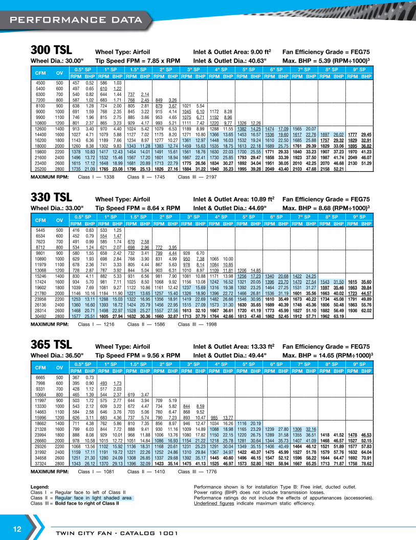
300 TSL Wheel Type: Airfoil Inlet & Outlet Area: 9.00 ft2 Fan Efficiency Grade = FEG75Wheel Dia.: 30.00" Tip Speed FPM = 7.85 x RPM Inlet & Outlet Dia.: 40.63" Max. BHP = 5.39 (RPM÷1000)3
330 TSL Wheel Type: Airfoil Inlet & Outlet Area: 10.89 ft2 Fan Efficiency Grade = FEG75Wheel Dia.: 33.00" Tip Speed FPM = 8.64 x RPM Inlet & Outlet Dia.: 44.69" Max. BHP = 8.68 (RPM÷1000)3
365 TSL Wheel Type: Airfoil Inlet & Outlet Area: 13.33 ft2 Fan Efficiency Grade = FEG75Wheel Dia.: 36.50" Tip Speed FPM = 9.56 x RPM Inlet & Outlet Dia.: 49.44" Max. BHP = 14.65 (RPM÷1000)3
PERFORMANCE DATA

WWW.TCF.COM 13
MAXIMUM RPM: Class I — 981 Class II — 1279 Class III — 1611
MAXIMUM RPM: Class I — 887 Class II — 1157 Class III — 1457
MAXIMUM RPM: Class I — 806 Class II — 1051 Class III — 1323
Legend: Performance shown is for installation Type B: Free inlet, ducted outlet.Class I = Regular face to left of Class II Power rating (BHP) does not include transmission losses.Class II = Regular face in light shaded area Performance ratings do not include the effects of appurtenances (accessories).Class III = Bold face to right of Class II Underlined figures indicate maximum static efficiency.
CFM OV0.5" SP 1" SP 1.5" SP 2" SP 3" SP 4" SP 5" SP 6" SP 7" SP 8" SP 9" SP
RPM BHP RPM BHP RPM BHP RPM BHP RPM BHP RPM BHP RPM BHP RPM BHP RPM BHP RPM BHP RPM BHP8080 500 332 0.889696 600 358 1.10 446 2.0811312 700 388 1.36 469 2.4712928 800 421 1.69 493 2.88 561 4.2114544 900 455 2.08 520 3.34 584 4.79 643 6.3116160 1000 491 2.55 551 3.89 609 5.42 665 7.06 765 10.4217776 1100 528 3.11 584 4.54 637 6.14 689 7.87 786 11.5219392 1200 566 3.75 618 5.27 667 6.94 715 8.75 809 12.69 893 16.7322624 1400 643 5.29 690 7.10 733 8.89 775 10.86 857 15.12 937 19.73 1011 24.4625856 1600 723 7.29 764 9.35 803 11.36 841 13.46 914 18.06 985 22.96 1056 28.28 1122 33.65 1183 38.9529088 1800 803 9.74 840 12.08 876 14.37 911 16.68 977 21.53 1041 26.80 1105 32.41 1167 38.21 1228 44.31 1285 50.36 1339 56.3932320 2000 884 12.75 918 15.36 951 17.95 983 20.48 1044 25.64 1103 31.24 1160 37.12 1217 43.26 1274 49.74 1330 56.46 1383 63.1635552 2200 966 16.37 997 19.24 1027 22.08 1057 24.92 1114 30.51 1169 36.39 1222 42.63 1273 49.02 1326 55.89 1377 62.80 1429 70.1538784 2400 1048 20.64 1077 23.80 1105 26.92 1132 29.99 1186 36.13 1237 42.28 1287 48.84 1335 55.63 1383 62.76 1430 69.98 1478 77.5842016 2600 1131 25.67 1157 29.03 1183 32.41 1209 35.82 1259 42.46 1307 49.03 1354 55.84 1400 63.03 1444 70.36 1488 78.00 1532 85.8645248 2800 1214 31.48 1239 35.16 1263 38.78 1287 42.43 1334 49.65 1379 56.67 1424 63.92 1467 71.29 1509 78.98 1551 87.05 1591 95.08
CFM OV0.5" SP 1" SP 1.5" SP 2" SP 3" SP 4" SP 5" SP 6" SP 7" SP 8" SP 9" SP
RPM BHP RPM BHP RPM BHP RPM BHP RPM BHP RPM BHP RPM BHP RPM BHP RPM BHP RPM BHP RPM BHP9900 500 301 1.0811880 600 324 1.34 404 2.5613860 700 351 1.67 424 3.0215840 800 381 2.07 446 3.52 508 5.1617820 900 413 2.57 471 4.10 528 5.85 582 7.7319800 1000 445 3.14 499 4.78 551 6.63 602 8.65 692 12.7521780 1100 479 3.83 529 5.77 577 7.54 624 9.65 712 14.1523760 1200 513 4.61 560 6.48 605 8.55 648 10.75 732 15.53 808 20.4827720 1400 583 6.51 625 8.71 664 10.91 702 13.33 776 18.54 848 24.16 915 29.9731680 1600 655 8.95 692 11.47 728 13.97 762 16.53 828 22.17 892 28.17 956 34.67 1016 41.28 1071 47.7635640 1800 728 11.99 761 14.82 794 17.67 825 20.45 885 26.41 943 32.89 1000 39.68 1057 46.90 1111 54.21 1163 61.70 1212 69.1139600 2000 801 15.66 832 18.88 862 22.06 890 25.10 946 31.49 999 38.32 1051 45.58 1102 53.05 1154 61.07 1204 69.20 1252 77.4343560 2200 876 20.16 904 23.68 931 27.16 958 30.63 1009 37.43 1059 44.67 1106 52.18 1153 60.15 1200 68.41 1247 77.03 1293 85.8547520 2400 950 25.39 976 29.24 1001 33.04 1026 36.86 1074 44.30 1121 51.96 1165 59.81 1209 68.22 1252 76.89 1295 85.83 1338 95.0751480 2600 1025 31.56 1049 35.72 1073 39.93 1096 44.05 1141 52.18 1184 60.18 1227 68.60 1268 77.31 1308 86.34 1348 95.75 1387 105.2155440 2800 1100 38.67 1123 43.23 1145 47.71 1166 52.09 1209 61.02 1250 69.69 1290 78.45 1329 87.51 1367 96.94 1404 106.61 1441 116.64
CFM OV0.5" SP 1" SP 1.5" SP 2" SP 3" SP 4" SP 5" SP 6" SP 7" SP 8" SP 9" SP
RPM BHP RPM BHP RPM BHP RPM BHP RPM BHP RPM BHP RPM BHP RPM BHP RPM BHP RPM BHP RPM BHP11990 500 273 1.3114388 600 294 1.63 367 3.1116786 700 319 2.02 385 3.6619184 800 346 2.51 405 4.27 461 6.2421582 900 374 3.08 428 4.98 480 7.11 528 9.3423980 1000 404 3.80 453 5.79 500 8.02 546 10.45 628 15.4226378 1100 434 4.61 480 6.73 523 9.09 566 11.66 646 17.1128776 1200 466 5.59 508 7.83 549 10.34 588 13.01 665 18.85 733 24.7433572 1400 529 7.88 567 10.53 603 13.23 637 16.12 704 22.41 770 29.28 831 36.3438368 1600 594 10.81 628 13.88 660 16.86 692 20.05 751 26.78 810 34.14 867 41.85 922 49.93 972 57.7843164 1800 660 14.46 691 17.97 720 21.33 749 24.78 803 31.95 856 39.83 908 48.08 959 56.70 1009 65.73 1056 74.75 1100 83.6147960 2000 727 18.95 755 22.84 782 26.67 808 30.41 858 38.04 907 46.44 954 55.19 1000 64.18 1047 73.83 1093 83.80 1137 93.8652756 2200 794 24.30 820 28.62 845 32.88 869 37.02 916 45.34 961 54.05 1004 63.21 1047 72.92 1089 82.78 1132 93.28 1174 104.0257552 2400 862 30.70 885 35.30 908 39.93 931 44.59 975 53.67 1017 62.81 1058 72.53 1097 82.52 1136 92.99 1175 103.79 1215 115.2462348 2600 930 38.16 952 43.23 973 48.20 994 53.21 1035 63.06 1075 72.93 1113 82.91 1151 93.63 1187 104.48 1223 115.77 1259 127.4067144 2800 998 46.75 1019 52.29 1039 57.72 1058 63.01 1097 73.81 1134 84.25 1170 94.77 1206 105.88 1241 117.44 1275 129.28 1308 141.24
490 TSL Wheel Type: Airfoil Inlet & Outlet Area: 23.98 ft2 Fan Efficiency Grade = FEG75Wheel Dia.: 49.00" Tip Speed FPM = 12.83 x RPM Inlet & Outlet Dia.: 66.31" Max. BHP = 63.89 (RPM÷1000)3
445 TSL Wheel Type: Airfoil Inlet & Outlet Area: 19.80 ft2 Fan Efficiency Grade = FEG75Wheel Dia.: 44.50" Tip Speed FPM = 11.65 x RPM Inlet & Outlet Dia.: 60.25" Max. BHP = 39.47 (RPM÷1000)3
402 TSL Wheel Type: Airfoil Inlet & Outlet Area: 16.16 ft2 Fan Efficiency Grade = FEG75Wheel Dia.: 40.25" Tip Speed FPM = 10.54 x RPM Inlet & Outlet Dia.: 54.44" Max. BHP = 23.89 (RPM÷1000)3
PERFORMANCE DATA

TWIN CITY FAN - CATALOG 100114
MAXIMUM RPM: Class I — 728 Class II — 949 Class III — 1195
MAXIMUM RPM: Class I — 658 Class II — 858 Class III — 1081
MAXIMUM RPM: Class I — 598 Class II — 780 Class III — 983
Legend: Performance shown is for installation Type B: Free inlet, ducted outlet.Class I = Regular face to left of Class II Power rating (BHP) does not include transmission losses.Class II = Regular face in light shaded area Performance ratings do not include the effects of appurtenances (accessories).Class III = Bold face to right of Class II Underlined figures indicate maximum static efficiency.
CFM OV0.5" SP 1" SP 1.5" SP 2" SP 3" SP 4" SP 5" SP 6" SP 7" SP 8" SP 9" SP
RPM BHP RPM BHP RPM BHP RPM BHP RPM BHP RPM BHP RPM BHP RPM BHP RPM BHP RPM BHP RPM BHP14680 500 247 1.6117616 600 265 1.98 331 3.720552 700 288 2.48 348 4.5023488 800 312 3.06 366 5.24 416 7.6326424 900 338 3.79 386 6.08 433 8.68 477 11.4629360 1000 365 4.66 409 7.08 452 9.86 493 12.79 567 18.8832296 1100 392 5.65 434 8.28 472 11.11 511 14.27 583 20.9135232 1200 420 6.81 459 9.61 495 12.61 531 15.94 600 23.02 662 30.3141104 1400 477 9.61 512 12.90 544 16.17 575 19.73 636 27.48 695 35.81 750 44.4346976 1600 536 13.22 567 17.00 596 20.66 624 24.46 678 32.79 731 41.75 783 51.28 833 61.25 878 70.8252848 1800 596 17.72 623 21.91 650 26.12 676 30.61 725 39.12 772 48.62 820 58.91 866 69.46 911 80.47 953 91.38 993 102.2958720 2000 656 23.17 681 27.89 705 32.52 729 37.16 775 46.65 818 56.68 861 67.51 903 78.61 945 90.30 987 102.64 1026 114.7164592 2200 717 29.78 740 35.00 762 40.12 784 45.23 826 55.32 867 66.04 906 77.28 945 89.20 983 101.28 1022 114.20 1060 127.3770464 2400 778 37.56 799 43.22 820 48.93 840 54.50 880 65.66 918 76.87 955 88.76 990 100.92 1026 113.98 1061 127.13 1097 141.1076336 2600 839 46.61 859 52.84 878 58.93 897 65.07 934 77.11 970 89.15 1005 101.56 1039 114.60 1072 128.05 1104 141.69 1137 156.1182208 2800 901 57.24 919 63.82 937 70.44 955 77.11 990 90.26 1023 102.91 1056 115.94 1088 129.35 1120 143.64 1150 157.84 1181 172.98
CFM OV0.5" SP 1" SP 1.5" SP 2" SP 3" SP 4" SP 5" SP 6" SP 7" SP 8" SP 9" SP
RPM BHP RPM BHP RPM BHP RPM BHP RPM BHP RPM BHP RPM BHP RPM BHP RPM BHP RPM BHP RPM BHP17970 500 223 1.9621564 600 240 2.43 299 4.6225158 700 260 3.02 314 5.4728752 800 282 3.74 331 6.41 376 9.3232346 900 306 4.65 349 7.43 392 10.66 431 13.9935940 1000 330 5.70 370 8.68 408 12.00 446 15.67 513 23.1439534 1100 355 6.95 392 10.10 427 13.62 462 17.46 528 25.7143128 1200 380 8.35 415 11.75 448 15.47 480 19.48 543 28.24 599 37.1650316 1400 432 11.81 463 15.79 492 19.79 520 24.14 575 33.61 629 43.94 678 54.3257504 1600 485 16.20 513 20.83 539 25.28 565 30.04 613 40.10 661 51.08 708 62.74 753 74.87 794 86.6964692 1800 539 21.69 564 26.90 588 31.99 611 37.03 656 47.95 699 59.71 741 71.94 783 84.96 824 98.54 862 111.92 898 125.2171880 2000 593 28.32 616 34.15 638 39.88 660 45.62 701 57.11 740 69.43 779 82.73 817 96.35 855 110.67 892 125.39 928 140.4879068 2200 648 36.37 669 42.78 690 49.29 709 55.35 748 67.97 784 80.79 820 94.80 855 109.32 890 124.39 924 139.66 959 156.0886256 2400 704 46.05 723 52.98 742 59.99 760 66.78 796 80.40 830 94.00 864 108.75 896 123.79 928 139.55 960 155.83 992 172.6693444 2600 759 57.10 777 64.71 794 72.12 812 79.86 845 94.48 877 109.01 909 124.34 940 140.41 969 156.48 999 173.71 1028 190.92100632 2800 815 70.10 832 78.35 848 86.39 864 94.47 895 110.35 926 126.29 956 142.34 985 158.81 1013 175.85 1041 193.71 1068 211.67
CFM OV0.5" SP 1" SP 1.5" SP 2" SP 3" SP 4" SP 5" SP 6" SP 7" SP 8" SP 9" SP
RPM BHP RPM BHP RPM BHP RPM BHP RPM BHP RPM BHP RPM BHP RPM BHP RPM BHP RPM BHP RPM BHP21750 500 203 2.3826100 600 218 2.94 272 5.6030450 700 237 3.68 286 6.6534800 800 257 4.55 301 7.77 342 11.3039150 900 278 5.62 318 9.05 356 12.86 392 16.9543500 1000 300 6.90 337 10.56 371 14.53 406 19.04 467 28.1247850 1100 323 8.43 357 12.28 389 16.58 420 21.12 480 31.1152200 1200 346 10.15 377 14.19 407 18.68 436 23.51 493 34.04 544 44.8360900 1400 393 14.32 421 19.11 448 24.06 473 29.26 523 40.73 572 53.21 617 65.9369600 1600 441 19.61 466 25.14 490 30.59 513 36.21 558 48.71 601 61.83 644 76.05 685 90.78 722 104.9878300 1800 490 26.24 513 32.60 535 38.80 556 44.94 596 57.91 635 72.10 674 87.19 712 102.88 749 119.20 784 135.62 817 151.8787000 2000 540 34.44 560 41.32 580 48.25 600 55.20 637 69.01 673 84.11 708 100.02 743 116.71 777 133.77 811 151.77 844 170.2095700 2200 590 44.21 609 51.97 627 59.55 645 67.12 680 82.24 713 97.86 745 114.49 777 132.13 809 150.45 840 168.98 872 188.98104400 2400 640 55.71 657 64.03 674 72.40 691 80.83 724 97.42 755 113.94 785 131.35 815 150.02 844 169.07 873 188.73 902 209.04113100 2600 690 69.09 707 78.50 722 87.32 738 96.55 768 114.23 798 132.26 826 150.24 854 169.56 881 189.38 908 210.05 935 231.35121800 2800 741 84.84 756 94.66 771 104.56 786 114.54 814 133.69 842 152.90 869 172.16 895 191.86 921 212.82 946 234.10 971 256.18
542 TSL Wheel Type: Airfoil Inlet & Outlet Area: 29.36 ft2 Fan Efficiency Grade = FEG75Wheel Dia.: 54.25" Tip Speed FPM = 14.20 x RPM Inlet & Outlet Dia.: 73.38" Max. BHP = 106.28 (RPM÷1000)3
600 TSL Wheel Type: Airfoil Inlet & Outlet Area: 35.94 ft2 Fan Efficiency Grade = FEG75Wheel Dia.: 60.00" Tip Speed FPM = 15.71 x RPM Inlet & Outlet Dia.: 81.19" Max. BHP = 175.88 (RPM÷1000)3
660 TSL Wheel Type: Airfoil Inlet & Outlet Area: 43.50 ft2 Fan Efficiency Grade = FEG75Wheel Dia.: 66.00" Tip Speed FPM = 17.28 x RPM Inlet & Outlet Dia.: 89.31" Max. BHP = 283.26 (RPM÷1000)3
PERFORMANCE DATA

WWW.TCF.COM 15
MAXIMUM RPM: Class I — 541 Class II — 705 Class III — 888
MAXIMUM RPM: Class I — 489 Class II — 638 Class III — 833
MAXIMUM RPM: Class I — 444 Class II — 579 Class III — 729
Legend: Performance shown is for installation Type B: Free inlet, ducted outlet.Class I = Regular face to left of Class II Power rating (BHP) does not include transmission losses.Class II = Regular face in light shaded area Performance ratings do not include the effects of appurtenances (accessories).Class III = Bold face to right of Class II Underlined figures indicate maximum static efficiency.
CFM OV0.5" SP 1" SP 1.5" SP 2" SP 3" SP 4" SP 5" SP 6" SP 7" SP 8" SP 9" SP
RPM BHP RPM BHP RPM BHP RPM BHP RPM BHP RPM BHP RPM BHP RPM BHP RPM BHP RPM BHP RPM BHP26625 500 183 2.8931950 600 197 3.59 246 6.8637275 700 214 4.49 258 8.0842600 800 232 5.54 272 9.49 310 13.9347925 900 251 6.84 287 11.02 322 15.75 354 20.6753250 1000 271 8.42 304 12.83 336 17.87 367 23.28 422 34.3558575 1100 292 10.31 323 15.06 351 20.16 380 25.90 434 38.0863900 1200 313 12.43 341 17.38 368 22.86 395 28.94 446 41.73 492 54.9174550 1400 355 17.47 381 23.45 405 29.42 428 35.88 473 49.87 517 65.05 558 80.7485200 1600 399 24.04 422 30.91 443 37.41 464 44.35 504 59.41 544 75.91 582 92.92 619 110.90 653 128.5995850 1800 443 32.10 464 39.93 484 47.55 503 55.07 539 70.90 574 88.14 609 106.47 644 126.02 677 145.72 709 166.05 739 186.08106500 2000 488 42.07 507 50.76 525 59.22 543 67.72 576 84.45 609 103.15 640 122.29 672 142.93 703 164.01 734 186.26 763 208.18117150 2200 533 53.95 550 63.37 567 72.89 583 82.03 615 100.70 645 119.91 674 140.32 703 161.97 731 183.73 760 207.18 788 230.86127800 2400 579 68.28 595 78.71 610 88.84 625 99.00 655 119.40 683 139.62 710 160.85 737 183.62 763 206.76 789 230.62 816 256.19138450 2600 625 85.00 639 95.93 653 106.92 668 118.51 695 140.12 722 162.13 747 183.93 773 208.12 797 232.08 821 257.01 846 283.66149100 2800 670 103.81 684 116.05 697 127.86 711 140.32 737 164.23 762 187.57 786 210.85 810 235.39 833 260.62 856 287.07 878 313.48
CFM OV0.5" SP 1" SP 1.5" SP 2" SP 3" SP 4" SP 5" SP 6" SP 7" SP 8" SP 9" SP
RPM BHP RPM BHP RPM BHP RPM BHP RPM BHP RPM BHP RPM BHP RPM BHP RPM BHP RPM BHP RPM BHP32585 500 166 3.5739102 600 178 4.39 223 8.47 45619 700 193 5.45 234 9.9952136 800 210 6.81 246 11.62 280 17.0058653 900 227 8.38 260 13.57 291 19.26 320 25.2965170 1000 245 10.30 275 15.73 304 21.91 332 28.55 381 41.8771687 1100 264 12.61 292 18.43 318 24.83 344 31.82 392 46.4778204 1200 283 15.22 309 21.41 333 28.05 357 35.38 403 50.98 445 67.2991238 1400 321 21.39 344 28.58 366 35.96 387 43.93 428 61.19 467 79.40 504 98.54104272 1600 361 29.49 381 37.67 401 45.95 420 54.47 456 72.87 492 93.00 527 114.25 560 135.99 590 157.08117306 1800 401 39.43 419 48.69 437 57.96 455 67.50 488 87.14 519 107.90 551 130.59 582 154.05 612 178.28 641 203.23 668 227.62130340 2000 441 51.41 458 61.96 475 72.64 491 82.92 521 103.50 550 125.83 579 149.96 607 174.45 636 201.13 663 227.34 690 254.99143374 2200 482 66.08 498 77.90 513 89.40 528 100.91 556 123.23 583 146.65 610 172.27 635 197.69 661 224.97 687 253.43 713 283.23156408 2400 523 83.34 538 96.37 552 109.02 565 121.12 592 145.99 617 170.46 642 196.94 666 224.40 690 253.23 714 283.04 737 312.60169442 2600 565 103.99 578 117.58 591 131.27 604 145.08 629 172.02 653 198.64 676 225.74 699 254.85 721 284.54 743 315.48 764 345.99182476 2800 606 127.22 618 141.75 631 157.11 643 171.88 666 200.70 689 229.63 711 258.47 732 287.71 753 318.81 774 351.46 794 383.95
CFM OV0.5" SP 1" SP 1.5" SP 2" SP 3" SP 4" SP 5" SP 6" SP 7" SP 8" SP 9" SP
RPM BHP RPM BHP RPM BHP RPM BHP RPM BHP RPM BHP RPM BHP RPM BHP RPM BHP RPM BHP RPM BHP39595 500 150 4.2847514 600 162 5.38 202 10.2455433 700 176 6.72 212 12.0863352 800 191 8.33 223 14.08 254 20.6471271 900 206 10.19 236 16.50 264 23.39 291 30.9379190 1000 223 12.63 250 19.22 276 26.67 301 34.60 346 51.0087109 1100 239 15.22 265 22.40 288 30.00 312 38.61 356 56.6195028 1200 257 18.54 280 25.91 302 34.03 324 43.01 366 62.12 404 81.90110866 1400 292 26.18 312 34.68 332 43.66 351 53.31 388 74.14 424 96.65 457 119.49126704 1600 327 35.64 346 45.88 364 55.90 381 66.13 414 88.68 446 112.67 478 138.66 508 165.12 536 191.57142542 1800 364 47.96 381 59.53 397 70.68 413 82.10 443 106.02 471 131.16 500 158.71 528 187.09 556 217.43 582 247.43 606 276.42158380 2000 401 62.87 416 75.51 431 88.25 445 100.39 473 125.96 499 152.83 525 181.82 551 212.22 577 244.27 602 276.81 626 309.70174218 2200 438 80.64 452 94.73 465 108.28 479 122.54 504 149.27 529 178.17 553 208.74 577 241.22 600 273.66 624 308.88 647 344.21190056 2400 475 101.55 488 116.96 501 132.56 513 147.44 537 177.21 560 207.27 583 239.86 604 272.22 626 307.55 647 342.52 669 380.27205894 2600 513 126.60 524 142.48 536 159.26 548 176.22 570 208.19 592 240.71 613 273.75 634 309.26 654 345.36 674 383.00 694 421.78221732 2800 550 154.68 561 172.45 572 190.34 583 208.36 604 243.47 625 278.76 645 313.82 664 349.25 683 386.92 702 426.45 721 467.55
890 TSL Wheel Type: Airfoil Inlet & Outlet Area: 79.19 ft2 Fan Efficiency Grade = FEG75Wheel Dia.: 89.00" Tip Speed FPM = 23.30 x RPM Inlet & Outlet Dia.: 120.50" Max. BHP = 1263 (RPM÷1000)3
807 TSL Wheel Type: Airfoil Inlet & Outlet Area: 65.17 ft2 Fan Efficiency Grade = FEG75Wheel Dia.: 80.75" Tip Speed FPM = 21.14 x RPM Inlet & Outlet Dia.: 109.31" Max. BHP = 776.60 (RPM÷1000)3
730 TSL Wheel Type: Airfoil Inlet & Outlet Area: 53.25 ft2 Fan Efficiency Grade = FEG75Wheel Dia.: 73.00" Tip Speed FPM = 19.11 x RPM Inlet & Outlet Dia.: 98.81" Max. BHP = 468.90 (RPM÷1000)3
PERFORMANCE DATA

TWIN CITY FAN - CATALOG 100116
DIMENSIONS ARE SUBJECT TO CHANGE. CERTIFIED DRAWINGS AVAILABLE ON REQUEST.
MOTORFR
MAX. FRAME
NH NUMBER OF
DH DIA. HOLES
ON CB DIA. B.C.EQUALLY SPACED
STRADDLINGCENTERLINE
ROTATION
LOC.
A
OUTLET END
MCMAX.
BTBELT TUBE WIDTH
MAX. SHEAVE DIA. NOTTO EXCEED BT - 1.00
THHSG. GAUGE SD
DIA. SHAFT
TA
AIR
FLOW
CA CB CC
INSIDE DUCT
DIA. B
.C.
O.D. F
LANGE
HOR - HORIZONTAL DISCHARGE
D
BE BF G
MM1.5 FOUR BHDIA. MTG. HOLES
FOUR BMCLIP HOLES
SUPPORTLEGS
HORIZONTAL BASE MOUNTEDHBM HCH
BB BD BN
SUSPENSIONCLIPS
HORIZONTAL CEILING HUNG
MOTOR LOCATIONVIEWED FROMOUTLET END
AB
C
D
EF
G
H
Horizontal
AC14028B
SIZE BB BD BE BF BH BM BN BT CA CB CC D DH FR G M MC NHSD
TA THCL I CL II CL III
122 1.00 23.25 1.06 23.13 0.44 0.56 19.75 5.25 16.56 18.50 19.75 12.00 0.56 184T 19.75 8.38 23.13 8 1.000 1.000 — 25.25 10
150 1.00 27.75 1.06 27.63 0.44 0.56 23.50 6.50 20.25 22.13 23.38 14.00 0.56 215T 23.38 10.19 25.73 8 1.000 1.187 — 29.75 10
182 1.50 28.25 1.06 29.19 0.44 0.56 27.75 6.50 24.69 26.75 28.00 16.00 0.69 256T 28.00 12.50 34.45 12 1.187 1.437 1.437 31.25 12
200 1.50 31.50 1.06 32.44 0.56 0.56 30.13 7.25 27.06 29.13 30.31 18.00 0.81 256T 30.31 13.66 36.20 12 1.437 1.437 1.437 34.50 12
222 1.50 35.50 1.31 35.94 0.56 0.56 33.13 8.00 30.06 32.13 33.38 20.00 0.81 286T 33.38 15.19 39.15 12 1.437 1.437 1.437 38.50 12
245 1.50 40.75 1.31 41.19 0.56 0.81 36.25 8.93 33.13 35.13 36.38 21.00 0.81 365T 36.38 16.69 43.61 12 1.437 1.937 1.937 43.75 12
270 1.50 44.25 1.31 44.69 0.56 0.81 39.63 9.75 36.50 38.50 39.75 23.00 0.81 365T 39.75 18.38 46.41 12 1.687 1.937 2.187 47.25 12
300 1.50 49.50 1.31 49.88 0.56 0.81 43.75 10.93 40.56 43.13 44.88 25.00 0.81 365T 44.88 20.94 49.38 16 1.937 2.187 2.437 52.50 10
330 1.50 54.75 1.31 55.13 0.56 0.81 47.88 12.00 44.63 47.25 49.00 27.00 0.81 365T 49.00 23.00 50.81 16 1.937 2.187 2.437 57.75 10
365 2.00 60.25 1.56 61.13 0.56 0.81 52.56 13.25 49.38 52.00 53.75 29.00 0.81 365T 53.75 25.38 53.75 16 1.937 2.437 2.437 64.25 10
402 2.00 66.75 1.69 67.38 0.81 0.81 57.56 14.75 54.38 57.50 59.75 33.00 0.81 405T 59.75 28.38 61.77 16 2.187 2.437 2.937 70.75 10
445 2.00 74.63 1.69 75.25 0.81 0.81 63.38 16.25 60.19 63.25 65.50 36.00 0.81 445T 65.50 31.25 66.72 16 2.437 2.687 3.437 78.63 10
490 2.00 82.38 1.69 83.00 0.81 0.81 69.44 18.00 66.25 69.38 71.63 39.00 0.81 445T 71.63 34.31 70.18 24 2.687 2.937 3.437 86.38 10
542 2.00 91.63 2.44 90.75 0.81 1.06 76.56 19.88 73.38 77.00 79.75 43.00 0.81 445T 79.75 38.38 74.01 24 2.937 3.437 3.937 95.63 10
600 2.50 100.63 2.44 100.75 0.81 1.06 85.38 22.13 81.19 84.75 87.50 47.00 0.81 445T 87.50 42.25 78.41 24 2.937 3.437 3.937 105.63 10
660 2.50 111.38 2.44 111.50 1.06 1.06 93.56 24.25 89.31 92.88 95.63 52.00 0.81 445T 95.63 46.31 82.77 24 3.437 3.937 3.937 116.38 10
730 2.50 123.50 2.44 123.63 1.06 1.06 102.94 26.88 98.75 104.38 107.13 57.00 0.81 445T 107.13 52.06 87.76 24 3.437 3.937 4.437 128.50 10
807 2.56 137.00 2.44 137.25 1.06 1.06 115.50 29.50 109.25 114.63 117.63 62.00 0.81 445T 117.63 57.31 93.25 24 3.937 4.437 4.937 142.13 7
890 2.56 151.13 2.44 151.38 1.06 1.06 126.56 32.63 120.31 126.06 128.75 68.50 0.81 445T 128.75 62.88 99.06 24 3.937 4.937 5.437 156.25 7
DIMENSIONAL DATA

WWW.TCF.COM 17
BTBELT TUBE WIDTH
(NOTE 3)
MOTORFR
MAX. FRAME NH NUMBER OF
DH DIA. HOLES
ON CB DIA. B.C.EQUALLY SPACED
STRADDLINGCENTERLINE
ROTATION
VIEWED FROM OUTLET END
THHSG. GAUGE
SDDIA. SHAFT
TA
AIRFLOW
AIRFLOW
AIRFLOW
AIRFLOW
AIRFLOW
CA
CB
CC
VUI - VERTICAL UP DISCHARGE WITH FLOOR MOUNT SUPPORT LEGS (SEE NOTE 2)
OD. FLANGE
DIA. B.C.
INSIDE DUCT
SUPPORT LEGSFOUR PLACES
NOTE 1
NOTE 1
1.50
4.002.00
BL
(4) .56 DIA.MTG. HOLES
NOTE 2
MCMAX.
45
45
DISCHARGE UPFLOOR MOUNT
DISCHARGE UPCEILING HUNG
DISCH. DOWNCEILING HUNG
DISCH. DOWNFLOOR MOUNT
NOTES:1. Two locking collars are included to prevent shifting of components.2. Support legs shown are provided as an accessory.3. Maximum sheave diameter not to exceed "BT" - 1.00.
VUI VUO VDI VDO
DIMENSIONS ARE SUBJECT TO CHANGE. CERTIFIED DRAWINGS AVAILABLE ON REQUEST.
Vertical
AC14029
SIZE BL BT CA CB CC DH FR MC NHSD
TA THCL I CL II CL III
122 21.75 5.25 16.56 18.50 19.75 0.56 184T 23.13 8 1.000 1.000 — 25.25 10
150 25.38 6.50 20.25 22.13 23.38 0.56 215T 25.73 8 1.000 1.187 — 29.75 10
182 33.00 6.50 24.69 26.75 28.00 0.69 256T 34.45 12 1.187 1.437 1.437 31.25 12
200 35.38 7.25 27.06 29.13 30.31 0.81 256T 36.20 12 1.437 1.437 1.437 34.50 12
222 38.00 8.00 30.06 32.13 33.38 0.81 286T 39.15 12 1.437 1.437 1.437 38.50 12
245 41.38 8.93 33.13 35.13 36.38 0.81 365T 43.61 12 1.437 1.937 1.937 43.75 12
270 44.75 9.75 36.50 38.50 39.75 0.81 365T 46.41 12 1.687 1.937 2.187 47.25 12
300 49.88 10.93 40.56 43.13 44.88 0.81 365T 49.38 16 1.937 2.187 2.437 52.50 10
330 54.00 12.00 44.63 47.25 49.00 0.81 365T 50.81 16 1.937 2.187 2.437 57.75 10
365 58.75 13.25 49.38 52.00 53.75 0.81 365T 53.75 16 1.937 2.437 2.437 64.25 10
402 64.75 14.75 54.38 57.50 59.75 0.81 405T 61.77 16 2.187 2.437 2.937 70.75 10
445 70.50 16.25 60.19 63.25 65.50 0.81 445T 66.72 16 2.437 2.687 3.437 78.63 10
490 76.63 18.00 66.25 69.38 71.63 0.81 445T 70.18 24 2.687 2.937 3.437 86.38 10
542 84.75 19.88 73.38 77.00 79.75 0.81 445T 74.01 24 2.937 3.437 3.937 95.63 10
DIMENSIONAL DATA

TWIN CITY FAN - CATALOG 100118
DIMENSIONS ARE SUBJECT TO CHANGE. CERTIFIED DRAWINGS AVAILABLE ON REQUEST.
BT BELT TUBE WIDTH
MOTOR FRMAX. FRAME
NH NUMBER OF
DH DIA. HOLES
ON CB DIA. B.C.EQUALLY SPACED
STRADDLINGCENTERLINE
THHSG. GAUGE
MCMAX.
SD DIA. SHAFT
TA
NOTE 1
NOTE 1
CH
CK
CGA A
CD
CE
2.002.75
CJ
CC CA
1.0
CURB CAPSEE NOTE 3
DISCHARGE CAPSEE NOTE 3
O.D. DISCH. CAP
AIRFLOW
O.D. HSG.
INSIDE SQ.
INSIDE DUCT
O.D. F
LANGE
VIEW A - AWITHOUT DISCHARGE CAP
NOTES:1. Two locking collars are included to prevent shifting of components.2. Maximum sheave diameter not to exceed BT - 1.00.3. Discharge cap and curb cap are optional accessories.
VRM - VERTICAL DISCHARGE WITH DISCHARGE CAP AND CURB CAP
Vertical w/Curb & Discharge Cap
AC14029D
SIZE BT CA CB CC CD CE CG CH CJ CK DH FR MC NHSD
TA THCL I CL II CL III
122 5.25 16.56 18.50 19.75 16.81 23.75 27.00 45.75 5.50 15.00 0.56 184T 23.13 8 1.000 1.000 — 25.25 10
150 6.50 20.25 22.13 23.38 20.50 27.38 30.00 50.75 6.00 15.00 0.56 215T 25.73 8 1.000 1.187 — 29.75 10
182 6.50 24.69 26.75 28.00 24.88 34.88 34.00 55.88 6.63 18.00 0.69 256T 34.45 12 1.187 1.437 1.437 31.25 12
200 7.25 27.06 29.13 30.31 27.25 37.38 40.00 62.25 6.75 21.00 0.81 256T 36.20 12 1.437 1.437 1.437 34.50 12
222 8.00 30.06 32.13 33.38 30.25 40.38 40.00 66.25 6.75 21.00 0.81 286T 39.15 12 1.437 1.437 1.437 38.50 12
245 8.93 33.13 35.13 36.38 33.31 43.38 46.00 74.75 7.00 24.00 0.81 365T 43.61 12 1.437 1.937 1.937 43.75 12
270 9.75 36.50 38.50 39.75 36.69 46.75 46.00 78.50 7.25 24.00 0.81 365T 46.41 12 1.687 1.937 2.187 47.25 12
300 10.93 40.56 43.13 44.88 40.81 51.00 53.00 87.25 7.75 27.00 0.81 365T 49.38 16 1.937 2.187 2.437 52.50 10
330 12.00 44.63 47.25 49.00 44.88 55.13 59.00 95.50 7.75 30.00 0.81 365T 50.81 16 1.937 2.187 2.437 57.75 10
365 13.25 49.38 52.00 53.75 49.63 59.88 60.00 102.00 7.75 30.00 0.81 365T 53.75 16 1.937 2.437 2.437 64.25 10
402 14.75 54.38 57.50 59.75 54.63 64.88 67.00 111.75 8.00 33.00 0.81 405T 61.77 16 2.187 2.437 2.937 70.75 10
445 16.25 60.19 63.25 65.50 60.44 69.63 73.00 123.13 8.50 36.00 0.81 445T 66.72 16 2.437 2.687 3.437 78.63 10
490 18.00 66.25 69.38 71.63 66.50 78.00 80.00 135.38 9.00 40.00 0.81 445T 70.18 24 2.687 2.937 3.437 86.38 10
542 19.88 73.35 77.00 79.75 73.63 88.75 86.50 154.50 9.25 49.63 0.81 445T 74.01 24 2.937 3.437 3.937 95.63 10
DIMENSIONAL DATA
WWW.TCF.COM 19
Fans shall be model TSL Tubular Centrifugal Inline Fans, of the non-overloading design, as manufactured by Twin City Fan & Blower, Minneapolis, Minnesota.
Fans shall be designed for maximum efficiency. Fans shall have a sharply rising pressure characteristic extending through the operating range and continuing to rise well beyond the efficiency peak to assure quiet and stable operation under all conditions. Horsepower characteristics shall be truly self-limiting and shall reach a peak in the normal selection area.
PERFORMANCE — Fans shall be tested in accordance with AMCA 211 and AMCA 311 test codes for air moving de-vices and shall be guaranteed by the manufacturer to deliver rated published performance levels. Fans shall be licensed to bear the AMCA certified ratings seal for both sound and air.
HOUSING — Housings shall be cylindrical and welded steel throughout. Inlets shall be fully streamlined. Housings shall be suitably braced to prevent vibration or pulsation.
WHEEL — Wheel diameters shall be in accordance with the standard sizes adopted by AMCA Standard 99-2414 for centrifugal tubular type fans. Fan wheel sizes 122 and 150 shall have single thickness plate-type blades. Fan wheel sizes 182 and larger shall have die-formed airfoil blades designed for maximum efficiency and quiet operation. Blades shall be continuously welded to the back plate and wheel cone. Partial welding is not acceptable. The wheel shall be specifically designed for inline fans to offer a higher and broader efficiency range. The back plate of the wheel shall be designed to offer lower resistance to the air leaving the wheel. Wheels shall be statically and dynamically balanced and the complete fan assembly shall be test balanced at or near the operating speed at the factory prior to shipment.
SHAFT — Shafts shall be AISI 1040 or 1045 hot rolled steel, accurately turned, ground, polished, and ring gauged for accuracy. Shafts shall be sized for the first critical speed of at least 1.43 times the maximum speed.
BEARINGS — Bearings shall be heavy duty, grease lubricated, anti-friction ball or roller, self-aligning, pillow block type and selected for an average bearing life (AFBMA L-50) in excess of 200,000 hours at the maximum fan RPM. Bearings shall be equipped with extended lubrication lines with grease fittings outside of the fan housing.
DRIVE — Motor sheaves shall be cast iron, variable pitch on applications 20 HP and smaller, and fixed pitch on 25 HP and larger.
INLET VANES — Inlet vanes, where specified, shall be of the external type for sizes 122 & 150 and nested for sizes 182 and larger. Inlet vanes shall be designed for economical, stable, and efficient air volume control at partial load conditions.
ACCESSORIES — When specified, accessories such as belt guards (standard or OSHA), weather covers, bolted or quick-opening access doors, inlet and outlet companion flanges, and other accessories as required by the application shall be provided by Twin City Fan & Blower to maintain one source responsibility.
FINISH AND COATING — The entire fan assembly, excluding the shaft, shall be thoroughly degreased and deburred before application of a rust-preventative primer. After the fan is completely assembled, a finish coat of paint shall be applied to the entire assembly. The fan shaft shall be coated with a petroleum-based rust protectant. Aluminum com-ponents shall be unpainted.
FACTORY RUN TEST — All fans with motors and drives mounted by Twin City Fan shall be completely assembled and test run as a unit at the specified operating speed prior to shipment. Each wheel shall be statically and dynamically balanced in accordance with ANSI/AMCA 204-96 “Balance Quality and Vibration Levels for Fans” to Fan Application Category BV-3, Balance Quality Grade G6.3. Balance readings shall be taken by electronic type equipment in the axial, vertical, and horizontal directions on each of the bearings. Records shall be maintained and a written copy shall be available upon request.
GUARANTEE — The manufacturer shall guarantee the workmanship and materials for its TSL Tubular Centrifugal Inline Fans for at least one (1) year from startup or eighteen (18) months from shipment, whichever occurs first.
ModelTSL
TYPICAL SPECIFICATIONS

TWIN CITY FAN & BLOWERWWW.TCF.COM
5959 TRENTON LANE N | MINNEAPOLIS, MN 55442 | PHONE: 763-551-7600 | FAX: 763-551-7601
CENTRIFUGAL FANS | UTILITY SETS | PLENUM & PLUG FANS | INLINE CENTRIFUGAL FANS
MIXED FLOW FANS | TUBEAXIAL & VANEAXIAL FANS | PROPELLER WALL FANS | PROPELLER ROOF VENTILATORS
CENTRIFUGAL ROOF & WALL EXHAUSTERS | CEILING VENTILATORS | GRAVITY VENTILATORS | DUCT BLOWERS
RADIAL BLADED FANS | RADIAL TIP FANS | HIGH EFFICIENCY INDUSTRIAL FANS | PRESSURE BLOWERS
LABORATORY EXHAUST FANS | FILTERED SUPPLY FANS | MANCOOLERS | FIBERGLASS FANS | CUSTOM FANS
INDUSTRIAL PROCESS ANDCOMMERCIAL VENTILATION SYSTEMS
©2018 Twin City Fan Companies, Ltd., Minneapolis, MN. All rights reserved. Catalog illustrations cover the general appearance of Twin City
Fan & Blower products at the time of publication and we reserve the right to make changes in design and construction at any time without notice.
Twin City Fan
Twin City Fan