Tschlin Photo Measuring Class
6
Facade Studies As - Built Techniques Studio Tschlin University of Washington College of Built Environments Department of Architecture The purpose of this handout is to illustrate perspective measurement techniques in order to produce drawings that are dimensionally accurate and convey the nuance of the Engadiner Farmhouse. General Concepts Photographing the Facade Field Measurements Working in Photoshop Using an Image in Vectorworks Photographing the Facade The accuracy of your perspective corrected photograph and the dimesions of your grid, in some measure depend upon the best possible angle and composition of your initial photograph. The best photographs to be used are those that are most ‘architecturally correct’. We wil discuss this as we begin to photograph each facade. Step 1 - Correct for Lens Barrel Distortion • Open your facade photograph and apply a distortion filter to compensate for your camera’s lens bar- rel distortion . (Filter > Distort > Lens Correction) • Slide the top most slider ( ‘Remove Distortion’) till the barreling is removed from the photograph. Step 2 - Create new layer to receive grid and measurements • create a new empty layer (shft + cmd + N) Step 3 - Use Vanishing Point Filter to Establish a Scaled Grid • Apply vanishing point filter (Filter > Vanishing Point) Facade Studies As - Built Drawing Techniques
-
Upload
kevin-driscoll -
Category
Documents
-
view
215 -
download
0
description
Photo measurement techniques developed for a University of Washington architecture course. The techniques were developed to assist with an historic building survey conducted by students in the alpine village of Tschlin, Switzerland.
Transcript of Tschlin Photo Measuring Class
Facade StudiesAs - Built Techniques
Studio TschlinUniversity of Washington College of Built EnvironmentsDepartment of Architecture
The purpose of this handout is to illustrate perspective measurement techniques in order to produce drawings that are dimensionally accurate and convey the nuance of the Engadiner Farmhouse.
General Concepts
Photographing the Facade Field Measurements Working in Photoshop Using an Image in Vectorworks
Photographing the FacadeThe accuracy of your perspective corrected photograph and the dimesions of your grid, in some measure depend upon the best possible angle and composition of your initial photograph. The best photographs to be used are those that are most ‘architecturally correct’. We wil discuss this as we begin to photograph each facade.
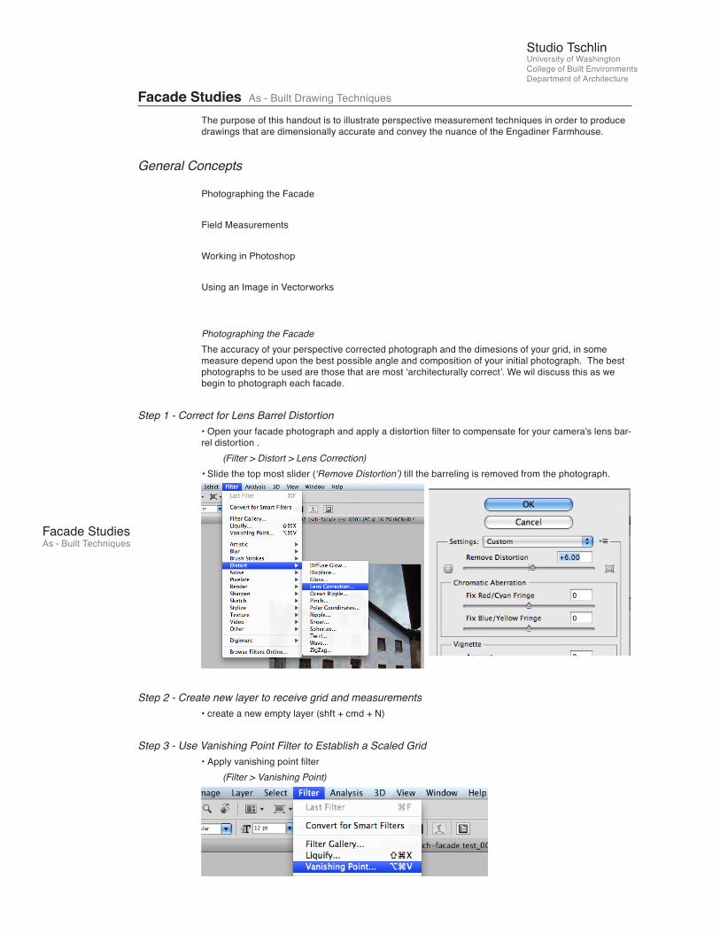
Step 1 - Correct for Lens Barrel Distortion• Open your facade photograph and apply a distortion filter to compensate for your camera’s lens bar-rel distortion . (Filter > Distort > Lens Correction)• Slide the top most slider (‘Remove Distortion’) till the barreling is removed from the photograph.
Step 2 - Create new layer to receive grid and measurements• create a new empty layer (shft + cmd + N)
Step 3 - Use Vanishing Point Filter to Establish a Scaled Grid• Apply vanishing point filter (Filter > Vanishing Point)
Facade Studies As - Built Drawing Techniques

Facade StudiesAs - Built Techniques
Studio TschlinUniversity of Washington College of Built EnvironmentsDepartment of Architecture
• Using the (‘Create Plane Tool’ selected by default) click the four corners of the perspective plane established with plumb lines and laser Distos during initial measuring and photographing.• Stretch the plane, using the middle handles (so as not to distort), to reach the enitire facade (i.e. roof peak, etc.)
Step 4 - Establish Baseline Measurements In Vanishing Point• While still in the Vanishing Point window, select the (‘Measure Tool’) from the left hand tool bar.
• Use the Measure Tool to trace one of the baseline measurements taken from the field. Hold the ‘cmd’ key to lock the measurement to the perspective grid while tracing field measurement.
• If there is one measurement that you have greater confidence in its accuracy, start with this one first.
Step 5 - Calibrating Measurements and Grid• The length in the measurement you just established will be arbitrary in photoshop. To give the measurement meaning, go to the upper left of the Vanishing Point window and replace the value in the ‘Length’ box with the accurate measurement (in meters) that you have been tracing.
Facade StudiesAs - Built Techniques
Studio TschlinUniversity of Washington College of Built EnvironmentsDepartment of Architecture
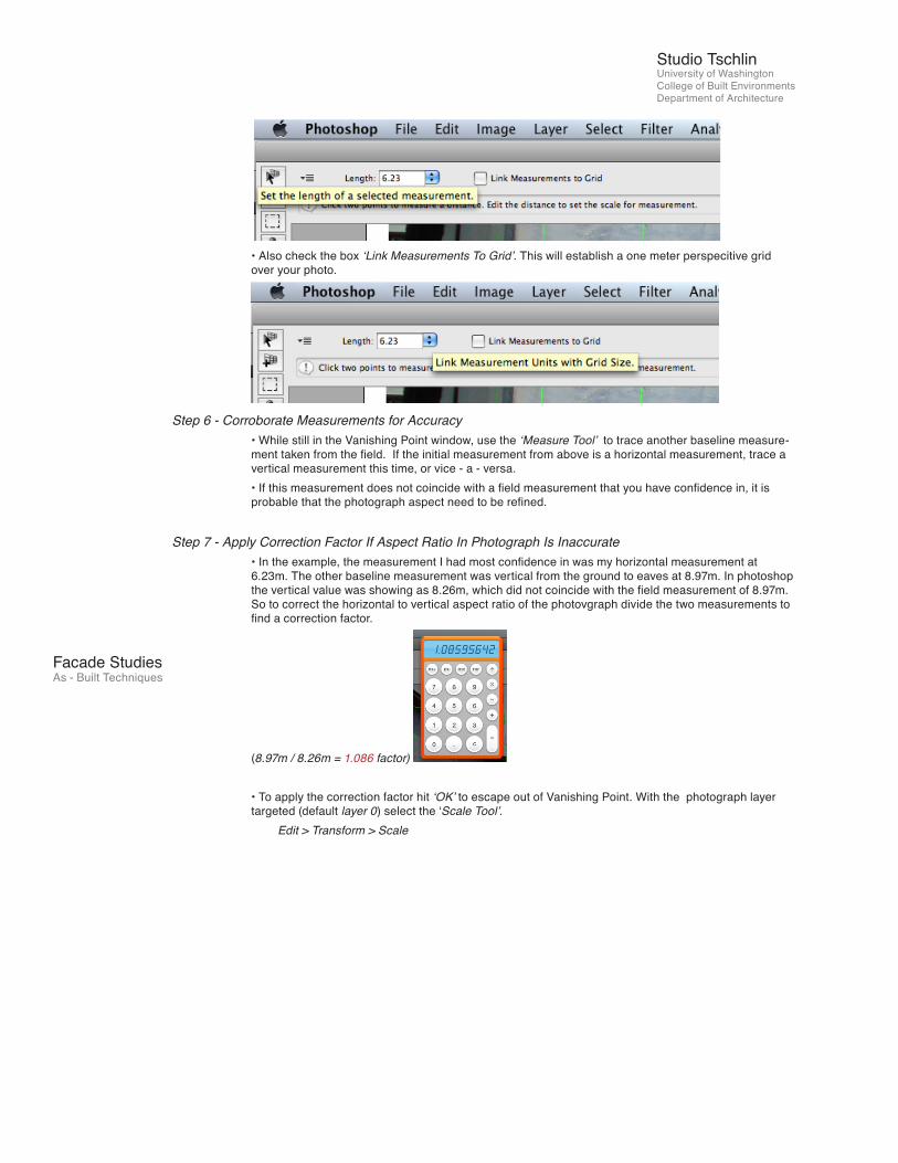
• Also check the box ‘Link Measurements To Grid’. This will establish a one meter perspecitive grid over your photo.
Step 6 - Corroborate Measurements for Accuracy• While still in the Vanishing Point window, use the ‘Measure Tool’ to trace another baseline measure-ment taken from the field. If the initial measurement from above is a horizontal measurement, trace a vertical measurement this time, or vice - a - versa. • If this measurement does not coincide with a field measurement that you have confidence in, it is probable that the photograph aspect need to be refined.
Step 7 - Apply Correction Factor If Aspect Ratio In Photograph Is Inaccurate• In the example, the measurement I had most confidence in was my horizontal measurement at 6.23m. The other baseline measurement was vertical from the ground to eaves at 8.97m. In photoshop the vertical value was showing as 8.26m, which did not coincide with the field measurement of 8.97m. So to correct the horizontal to vertical aspect ratio of the photovgraph divide the two measurements to find a correction factor.
(8.97m / 8.26m = 1.086 factor)
• To apply the correction factor hit ‘OK’ to escape out of Vanishing Point. With the photograph layer targeted (default layer 0) select the ‘Scale Tool’. Edit > Transform > Scale

Facade StudiesAs - Built Techniques
Studio TschlinUniversity of Washington College of Built EnvironmentsDepartment of Architecture
• Input the correction factor to correct the height (or width depending on your case) discrepency be-tween the field measurment and measurement in Photoshop.
Step 8 - Confirm corrected baseline measurements• Target your measurement layer and return to Vanishing Point. (alt + cmd + v)• Select the ‘Measure Tool’ and stretch the inaccurate measurement (8.26m in the example) to meet the field measurement points. If done accurately this previously inaccurate measurement should reflect the field measurement very closely. • At this point both field measurements should be accurately reflected in Photoshop.
Step 9 - Exporting Grid And Measurement From Photoshop• While still in Vanishing Point, select the ‘Settings and Cmds f/ Vanishing Point’ pulldown menu. • Select and check each of the following: Render Grids to Photoshop, Render Measurements to Photo-shop, Return 3D Layer to Photoshop. • Select ‘OK’ to exit out of Vanishing Point.• Allow your computer time to process these intensive commands.
Step 10 - Export Perspective Corrected ‘Elevation’• Photoshop will have generated a new 3D layer. Turn off your measurement layer and your field pho-tograph layer.

Facade StudiesAs - Built Techniques
Studio TschlinUniversity of Washington College of Built EnvironmentsDepartment of Architecture
• In the new 3D layer, double click the sub-layer ‘temp 0’ to open it in a new window.
• The new window will display your photograph in an elevational view with the 1m grid and measure-ments displayed overlayed on top. Perform a ‘Save As’ to rename and save the current .psb file as a Photoshop .psd file in your folder under facade assignment on Roger. File > Save As > Photoshop
• Save and close your other photoshop file in the same location. Exit out of Photoshop.
Step 11 - Import Elevational Photograph Into Vectorworks• Open up a new file in Vectorworks for your facade drawing.• ‘Save’ your new drawing in your Facade Assignment folder with the Haus number, facade (east, north, etc) and your initials. (i.e. haus 81_east facade KD )
• Import your elevation photograph into Vectorworks. File > Import > Image Image File• Follow default commands for importing.• Move photograph to background design layer or similar.
Step 12 - Scale Elevational Photograph• Your photograph may be easily scaled in Vectorworks because of the 1m grid you established in Photoshop. • Draw a 10m line in Vectorworks to scale the photograph against. • With your photograph selected, select a corner and stretch the image (with shift selected to lock the aspect...important!) to meet the reference line you have drawn. 10 grid spaces should equal the length of the line.• Verify the scale of of the image by tracing over one of your field measurements with a line in Vector-works. The length of the line should match the length of the field measurement with a high degree of accuracy. • If you are confident with the accuracy of the scale and the image, position the image in the center of

Facade StudiesAs - Built Techniques
Studio TschlinUniversity of Washington College of Built EnvironmentsDepartment of Architecture
your page and right click to lock it in place.
Step 13 - Begin Drafting Your Facade• Using your image as an underlay, begin drafting your facade on an appropriate design layer other than your background or photo layer.
Important Points to Remember:
- Continue to use field measurements to check for the accuracy of your drawing.- There is only one accurate plane in the photograph that is accurate for use as a drafting underlay. Recessed window, doors, and balconies and other elements that are in front or behind your primary plane must be repositioned relative to the primary plane.- When in doubt, verify with field measurements.